
ABSTRACT Title of Thesis: INTEGRATION OF … · Title of Thesis: INTEGRATION OF SUSTAINABLE...
80
ABSTRACT Title of Thesis: INTEGRATION OF SUSTAINABLE INFRASTRUCTURE AT A NEIGHBORHOOD SCALE Michael Binder, Master of Architecture, 2006 Thesis directed by : Professor Brian Kelly University of Maryland School of Architecture By concentrating power generation, water treatment and waste management facilities at large centralized sites on the edge of its cities, modern industrial society allows us to ignore our responsibility for the damage we are doing to the environment. This thesis project proposes the integration and distribution of neighborhood-scaled power and waste management functions throughout our urban centers, demonstrating the efficacy of localized infrastructure based on sustainable natural and man-made cycles, making it simultaneously beautiful and providing a desirable amenity to the residents. The heart of this thesis project is the design for an indoor garden space which also integrates solar power management, nature-inspired wastewater treatment and solid waste recycling. The program will include an environmental education center using the facility as an operational example. A site in Northwest Washington DC, bounded by New Jersey Ave., New York Ave., North Capitol and K Streets has been selected for its redevelopment opportunities.
Transcript of ABSTRACT Title of Thesis: INTEGRATION OF … · Title of Thesis: INTEGRATION OF SUSTAINABLE...

ABSTRACT
Title of Thesis: INTEGRATION OF SUSTAINABLE INFRASTRUCTURE AT A NEIGHBORHOOD SCALE
Michael Binder, Master of Architecture, 2006
Thesis directed by : Professor Brian Kelly
University of Maryland School of Architecture By concentrating power generation, water treatment and waste management
facilities at large centralized sites on the edge of its cities, modern industrial society
allows us to ignore our responsibility for the damage we are doing to the environment.
This thesis project proposes the integration and distribution of neighborhood-scaled
power and waste management functions throughout our urban centers, demonstrating the
efficacy of localized infrastructure based on sustainable natural and man-made cycles,
making it simultaneously beautiful and providing a desirable amenity to the residents.
The heart of this thesis project is the design for an indoor garden space which also
integrates solar power management, nature-inspired wastewater treatment and solid waste
recycling. The program will include an environmental education center using the facility
as an operational example. A site in Northwest Washington DC, bounded by New Jersey
Ave., New York Ave., North Capitol and K Streets has been selected for its
redevelopment opportunities.

INTEGRATION OF SUSTAINABLE INFRASTRUCTURE AT A NEIGHBORHOOD SCALE:
by
Michael P. Binder
Thesis submitted to the Faculty of the Graduate School of the University of Maryland, College Park in partial fulfillment
of the requirements for the degree of Master of Architecture
2006
Advisory Committee:
Professor Brian Kelly Chair Professor Carl Bovill Professor Gary Bowden

ii
Dedication This thesis is dedicated with love to my wife, Martha Wetherholt, without whose constant encouragement and support this work would never have been possible. Acknowledgements I would like to acknowledge the following people for their assistance in the completion of this thesis project:
Brian Kelly Gary Bowden Carl Bovill Debbie Bauer Rawle Sawh Andy Murray Nastaran Zandian Aaron Kreinbrook Sahin Ariloglu Jamie Brady Jef Zaborski Jenny Castronuovo Brian Carroll

iii
TABLE OF CONTENTS
page
1 INTRODUCTION .................................................................................................. 1 2 SITE ANALYSIS ................................................................................................... 3
2.1 HISTORY ................................................................................................... 5 2.2 PHYSICAL DESCRIPTION.................................................................... 13
2.2.1 Surface Conditions ....................................................................... 13 2.2.2 Infrastructure................................................................................. 13 2.2.2 Vegetation ..................................................................................... 15 2.2.3 Topography................................................................................... 16 2.2.4 Hydrology ..................................................................................... 17 2.2.5 Access to Solar Income................................................................. 18
2.3 CONTEXT................................................................................................ 19 2.4 ACCESS TO PUBLIC TRANSPORTATION ......................................... 23 2.5 NEW COMMUNITIES INITIATIVE CITYWIDE MASTER PLAN .... 26 2.6 ZONING REGULATIONS ...................................................................... 30
3 PRECEDENT ANALYSIS................................................................................... 32 3.1 Adam J. Lewis Center for Environmental Studies at Oberlin College – .. 32 3.2 SOUTH BURLINGTON, VERMONT LIVING MACHINE.................. 35 3.3 MILLENIUM CENTER, SHEFFIELD, ENGLAND............................... 37 3.4 INSTITUTE FOR FORESTRY & NATURE RESEARCH..................... 39
4 PROGRAM........................................................................................................... 41 4.1 DESCRIPTION OF PROGRAM ELEMENTS........................................ 41 4.2 AREA CALCULATIONS........................................................................ 47
5 DESIGN APPROACH ......................................................................................... 48 5.1 CONCEPTUAL DESIGN STRATEGIES ............................................... 48 5.2 ALTERNATIVE SITE PARTIS............................................................... 49 5.3 BUILDING FORMS................................................................................. 55
6 DEVELOPMENT OF FINAL DESIGN .............................................................. 57 6.1 SITE DESIGN .......................................................................................... 57 6.2 BUILDING DESIGN................................................................................ 62
7 CONCLUSIONS................................................................................................... 70 APPENDIX A – INTRODUCTION TO LIVING MACHINES™................................. A1 REFERENCES .....................................................................................................................

1
1 INTRODUCTION Since the dawn of the Industrial Age, developed countries (including the U.S.) have made great strides in improving quality of life for their citizens. Many of these improvements are embodied in our modern infrastructures : transportation, power generation and sewage treatment in particular. These improvements have come with a price, however. The industrial processes that we have come to depend on involve the use of toxic chemicals and create pollution on a global scale. We are poisoning the ecosystem that sustains us and all other life on Earth. Another hallmark of the Industrial Age has been centralization. In the interests of economy and expediency, we create large regional power plants and waste treatment facilities. When these facilities fail, the impact is widespread, causing power outages for hundred of thousands of people, or allowing large quantities of untreated sewage to overflow into our rivers, lakes and oceans. People have become too comfortable with the system described above. They consume power without much regard for how it is generated, they discard waste (solid and liquid) without having any real idea what happens to it. Many people are now aware of the impending crisis we face with regard to both energy and waste, but they feel powerless to do anything. They have ceded responsibility for these services to large corporate and government organizations over which they feel they have no control, In this thesis project, we will begin to explore one path to a solution for the issues cited above. My thesis proposes the reintegration of infrastructure such as power generation and wastewater treatment into the urban context. It explores the creation of a network of small, distributed wastewater facilities to replace the large centralized facilities commonly used today. It also considers the creation of a solar power cooperative in which the majority of homes, apartments and other buildings in a given community include substantial arrays of solar collectors on their roofs and facades. The potential success of this thesis depends largely on the use of relatively new sustainable technologies for processing wastewater. Solar Aquatic Systems, often referred to by the trade name of “Living Machines™”, purify wastewater using a process inspired by nature. Instead of chemicals such as chorine, the process uses plants, fish, snails and microorganisms to consume the waste and make the water clean enough to release into the environment, if not necessarily clean enough to drink. The waste treatment plant can thereby be transformed from an industrial facility into a garden of sorts. Another important aspect of this nature-inspired infrastructure is stormwater management. Surface water from rain and snow generally contain all sorts of contaminants including salt, oil, gasoline and other toxic substances. This water is typically allowed to simply run off into storm sewers and ultimately into our rivers and

2
lakes. After a particularly heavy downpour, the storm sewers often overflow. In a city like Washington DC, where many of the antiquated storm and sanitary sewers are combined, this overflow often means that raw sewage also overflows, creating a serious public health issue. The waste treatment plants also become incapable of handling the volume of water and allow the raw waste to flow directly into the river or lake or ocean. An alternative to employing this system of regional storm sewers is to use artificial wetlands constructed to filter the contaminated rain water and allow the majority of it to soak into the ground rather than run off into the area waterways. This thesis project will begin to consider the design issues associated with making such constructed wetlands (sometimes called bioswales) part of the urban landscape. Finally, this thesis project attempts to address the issue of public education. It is not enough to create a sustainable infrastructure that works and is invisible to the people it serves. This thesis proposes that the infrastructure should be a part of people’s daily experience with the built environment. Ideally, the infrastructure becomes a source of inspiration and understanding for the community it serves. In the case of the Living Machine™, infrastructure can even provide the amenity of an indoor garden space. The constructed wetlands can be part of a way-finding network that guides people through the community. In the mid nineteenth century, the people of London built what came to be called the “Cathedral of Sewage”. It was a beautifully designed and constructed Victorian building which housed nothing more (or less) than a sewage pumping station. People were rightfully proud of their innovation and wanted to express it architecturally. We are now on the cusp of a new, sustainable revolution that will, I hope, transform our culture and our built environment. This thesis will begin to explore the architectural forms that will express our new pride in finding a better way to live well, and in harmony with the natural environment.

3
2 SITE ANALYSIS
Photo 1 – Aerial View of Site (highlighted) with surrounding context.

4
The site for the thesis project is located in Washington DC, approximately 0.4 miles
northwest of Union Station (see Figure 1). It is comprised of 46 acres of land bounded
on the north by New York Avenue, on the south by K Street, on the east by North Capitol
Street, and on the west by New Jersey Avenue. An aerial view of the site is shown in
Photo 1 above, and it has not changed significantly since this photo was taken. A
diagram highlighting the location of the existing buildings is shown in Figure 2 and a
rough massing perspective of the buildings on site is shown in Figure 3.
Figure 1 – Larger context of the neighborhood withing Washington DC.
5
2.1 HISTORY
The site is located in an area of Washington DC generally known as NOMA, an acronym
for North of Massachusetts Avenue. Some of earliest settlers in this area of town were
Irish immigrants, who called the area Swampoodle, a reference to the marshy conditions
created by the flow of Tiber Creek. This area was considered very rough, a common
hangout for prostitutes, thugs, gangs of unruly boys and other unsavory characters. After
the Civil War, the Tiber was completely enclosed by the city sewer system, and the
construction of Union Station destroyed much of the residential area at the heart of
Swampoodle 1. The area became a mixture of industrial uses abutting the railyards, of
blighted densely packed rowhouses and alley dwellings. After World War II, there was a
call for reform of the housing conditions in the area, and most of the dwellings were
demolished and redeveloped through urban renewal programs. These programs included
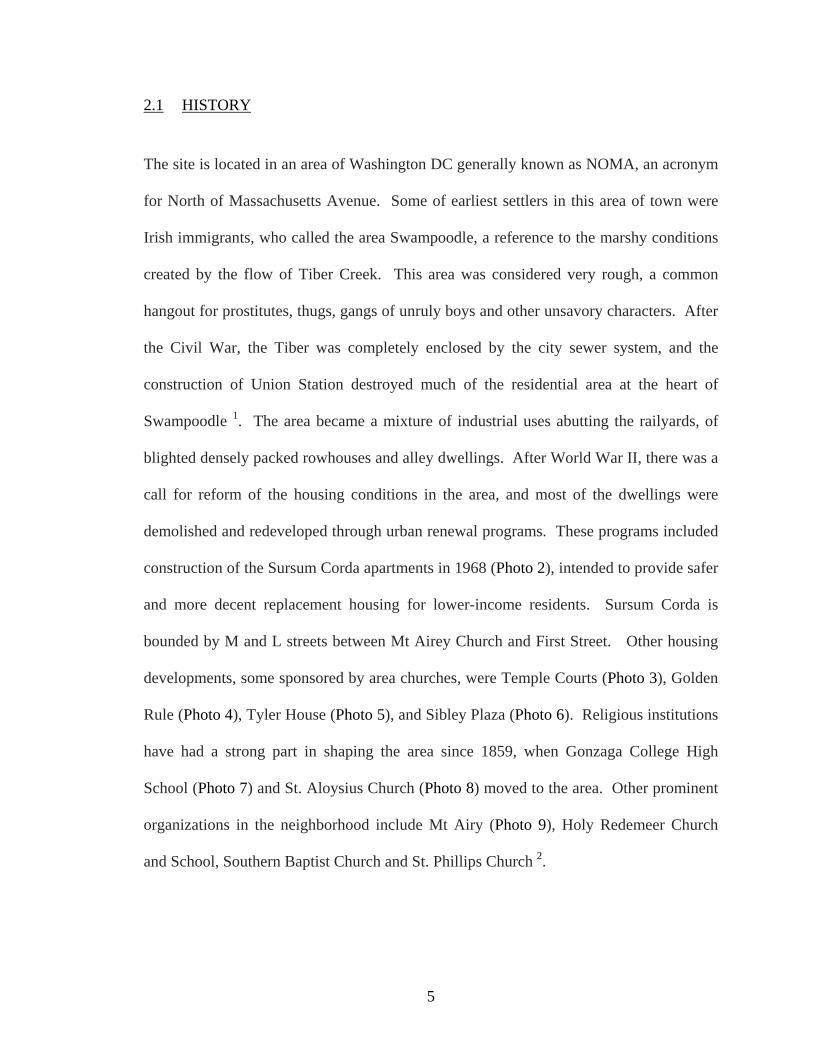
construction of the Sursum Corda apartments in 1968 (Photo 2), intended to provide safer
and more decent replacement housing for lower-income residents. Sursum Corda is
bounded by M and L streets between Mt Airey Church and First Street. Other housing
developments, some sponsored by area churches, were Temple Courts (Photo 3), Golden
Rule (Photo 4), Tyler House (Photo 5), and Sibley Plaza (Photo 6). Religious institutions
have had a strong part in shaping the area since 1859, when Gonzaga College High
School (Photo 7) and St. Aloysius Church (Photo 8) moved to the area. Other prominent
organizations in the neighborhood include Mt Airy (Photo 9), Holy Redemeer Church
and School, Southern Baptist Church and St. Phillips Church 2.

6
Figure 2 – Existing Site Utilization.

7
Figure 3 – Aerial perspective view with approximate massing of buildings, as created by GoogleEarth database.
Photo 2 – View of Sursum Corda Cooperative Apartments, built in 1968 as part of urban renewal programs. Buildings are in better condition than most in the neighborhood, but may not be suitable for inclusion in new mixed-income redevelopment.
8
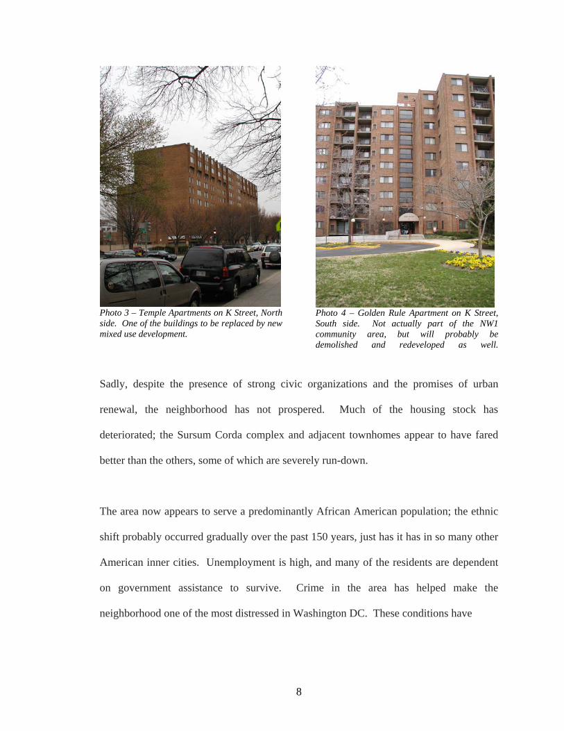
Photo 3 – Temple Apartments on K Street, North side. One of the buildings to be replaced by new mixed use development.
Photo 4 – Golden Rule Apartment on K Street, South side. Not actually part of the NW1 community area, but will probably be demolished and redeveloped as well.
Sadly, despite the presence of strong civic organizations and the promises of urban
renewal, the neighborhood has not prospered. Much of the housing stock has
deteriorated; the Sursum Corda complex and adjacent townhomes appear to have fared
better than the others, some of which are severely run-down.
The area now appears to serve a predominantly African American population; the ethnic
shift probably occurred gradually over the past 150 years, just has it has in so many other
American inner cities. Unemployment is high, and many of the residents are dependent
on government assistance to survive. Crime in the area has helped make the
neighborhood one of the most distressed in Washington DC. These conditions have

9
Photo 5 – Tyler House Apartments at the corner of NewYork Ave and North Capitol Street is one of the more attractive complexes in the area, and will be spared from demolition according to the NCCI Master Plan.
Photo 6 – Sibley Plaza, located on North Capitol Street, will be demolished under the City’s plan and be replaced with mid-rise mixed-use development.

10
helped bring the site to the attention of the City government once more. It is to be the
first project developed under the New Communities Citywide Initiative (NCCI). The
neighborhood has been North-West One (NW1) after the 1960’s designation for urban
renewal.
Under the NCCI, most of the buildings within the site would be demolished to make
room for new housing and mixed used buildings (see discussion of the NCCI Master Plan
below) 2. It is tempting to suggest that Sursum Corda and some of the other buildings
might be saved from demolition, but apparently they are inadequate to attract the market-
rate renters that the DC government hopes to attract to the area. The major difference
between the NCCI and past urban renewal programs, it would seem, is the priority given
to creating a mixed-income population, not simply to provide better housing for low-
income residents.

11
Photo 7 – Gonzaga College High School is located south of the neighborhood on North Capitol Street but still creates a strong presence.
Photo 8 – St. Aloysius Church, which faces the SE corner of the NW1 site, is another strong anchor of the community.

12
Photo 9 – Mt Airy Church is located within the NW1 community. It will be preserved under the NCCI Master Plan. Currently, its front faces L sStreet, which is little more than an alley, and a rather dismal apartment complex on the other side.

13
2.2 PHYSICAL DESCRIPTION
2.2.1 Surface Conditions Approximately 15% of the site is greenspace, some of it enclosed by chain-link fence as
playgrounds for the schools. This greenspace is located almost exclusively along the
western boundary of the site (New Jersey Avenue).
The remaining 85 % of the site is paved, with only small tree-lawns and small yards
fronting some of the buildings. The streets and alleys on the interior run N-S and E-W,
but are generally discontinuous, even for pedestrian traffic (only M Street all the way
across the site from E to W). This gives the entire neighborhood a rather closed sensation
on the interior, perhaps by design.
2.2.2 Infrastructure Street surfaces on the interior of the site (First Street and L Street) are seriously
deteriorated but serviceable. These streets delineate the storm sewer lines through the
community as well, as shown in Figure 4. Much of downtown Washington DC still has
combined sanitary and storm sewers; This includes the Tiber Creek trunk line that passes
along the west edge of the site (under North Capitol Street). The sanitary sewers within
the site have been separated from the storm sewers, probably during the 1960
rehabilitation.

14
Figure 4 – Sewer Line Map from DC Water Authority
15
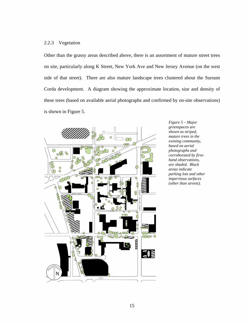
2.2.3 Vegetation Other than the grassy areas described above, there is an assortment of mature street trees
on site, particularly along K Street, New York Ave and New Jersey Avenue (on the west
side of that street). There are also mature landscape trees clustered about the Sursum
Corda development. A diagram showing the approximate location, size and density of
these trees (based on available aerial photographs and confirmed by on-site observations)
is shown in Figure 5.
Figure 5 – Major greenspaces are shown as striped, mature trees in the existing community, based on aerial photographs and corroborated by first-hand observations, are shaded. Black areas indicate parking lots and other impervious surfaces (other than streets).

16
2.2.4 Topography The site slopes downhill from New York Avenue on the northwest towards the
intersection of K Street and North Capitol Street on the southeast (see Figure 6). This
topography yields a modest opportunity to exploit the change in grade to increase access
to solar energy (stepping the buildings up the grade).
Figure 6 – Topography of the site, showing how the site slopes relatively gently from the northwest downward to the southeast corner. The contours represent 1 meter increments, starting at 7m on the lower-right and climbing to 28m. The total change in elevation across the site is about 18 m (60 ft).

17
2.2.5 Hydrology The topography of the site suggests that storm-water will run off to the southeast corner
(Figure 7). If we wish to retain storm-water on site (for filtration, irrigation, etc.), this
will probably have to occur on the southern boundary, along K Street. The southwest
corner (K and North Capitol) would be the most effective from a topographic and
hydrological perspective.
Figure 7 – Water run-off pattern. Generally, the site is graded to funnel run-off along streets (both north-south and east-west.

18
2.2.6 Access to Solar Income As noted above, the site is relatively flat, and slopes downward slightly to the south.
There are no features, artificial or natural, which would tend to shadow the site
significantly. The figure below shows that until about 2 pm on the winter solstice, the
proposed site would be free of shadows from surrounding buildings.
Figure 8 – Shadowing at 2 pm on winter solstice, based on development plans from the City.

19
The existing and proposed high-rise apartments on the southern border of the site may
create some local shadowing issues. If this is found to be a problem, it may be possible
to augment solar collection on the high-rise buildings to compensate for the buildings that
are shadowed to the north of them. No significant problems are anticipated regarding
access to daylight and to direct solar radiation.
2.3 CONTEXT
The basic site strategy for the community appears to have been to create a buffer of
apartment, institutional / civic (schools) and commercial buildings around the perimeter
of the site, creating a quieter and more intimate environment on the interior, where the
garden apartments and townhomes reside. The higher and larger buildings are around the
outside, the lower and smaller ones are in the center (see Figure 3). This arrangement
helps create a better transition between the residential environment of the site, and the
industrial / commercial / institutional context that surrounds it on the east, south, and west
sides (Photo 10 through Photo 13). Indeed, the buffer is least significant on the north side
of the site where the residential land-use continues north of New York Avenue (row-
houses, two-story mixed use buildings – Photo 14).

20
Photo 10 – East Boundary of NW1 Site. Looking along North Capitol Street from the corner of K Street, with the U.S. Capitol Dome clearly visible at the end of the street (looking South).
Photo 11 – East Boundary of NW1 Site. Looking North along North Capitol Street from the corner of K Street. St. Phillips Baptist Church is in a prominent landmark.

21
Photo 12 – West Boundary of NW1 Site, looking South along New Jersey Avenue. The Temple Bible School is in the foreground.
Photo 13 – South Boundary of NW1 Site, looking East along K Street. It is anticipated that the entire K-Street corridor will be redeveloped in coming years, replacing lower density land uses like th rowhouses seen here with mid-rise and high-rise apartments (up to 90 feet) and mixed-use buildings.

22
Photo 14 – Northern boundary of the NW1 Site, showing the lower density neighborhood to the North. The North edge of the neighborhood will be largely unchanged (except for renovation), and no buffer zone of taller apartments is needed here.
Given the nature of the buffer described above, it follows that the buildings on the site’s
interior do not directly connect to prominent landmarks outside of the site. The Capitol
Dome is clearly visible from the edges of the site, however, especially along North
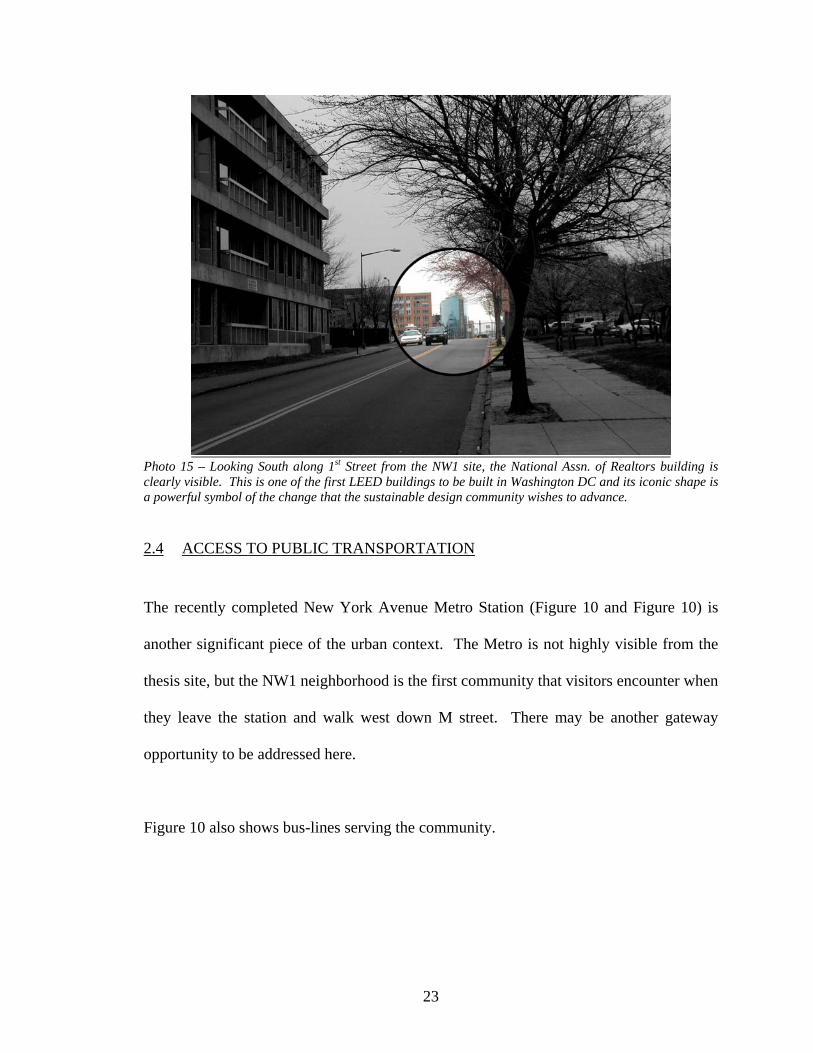
Capitol Street (Photo 10) and New Jersey Avenue. It has also been observed that 1st
Street (facing south) provides a clear unobstructed view of the National Association of
Realtors building several blocks south (Photo 15). This building is important because it
is one of the first LEED rated buildings constructed in Washington. Given its iconic
form and environmental significance, the NAR building might be another alignment
opportunity (Figure 9).
23
Photo 15 – Looking South along 1st Street from the NW1 site, the National Assn. of Realtors building is clearly visible. This is one of the first LEED buildings to be built in Washington DC and its iconic shape is a powerful symbol of the change that the sustainable design community wishes to advance.
2.4 ACCESS TO PUBLIC TRANSPORTATION
The recently completed New York Avenue Metro Station (Figure 10 and Figure 10) is
another significant piece of the urban context. The Metro is not highly visible from the
thesis site, but the NW1 neighborhood is the first community that visitors encounter when
they leave the station and walk west down M street. There may be another gateway
opportunity to be addressed here.
Figure 10 also shows bus-lines serving the community.

24
Figure 9 – View Corridors from the NW1 site and into it. Visual connections with the Capitol Dome and the NAR LEED building. The M St. and NY Ave. corridors represent gateways into the NW1 neighborhood.

25
Figure 10 – Access to Public Transportation. Metrobus routes provide reliable public transportation for the NW1 neighborhood. The recently opened New York Avenue Metro rail station has entrances along both New York Avenue and M Street. Metro access will be an essential element in the development of a sustainable mixe-income community here. (bus route map is taken directly from graphics included in the NCCI Master Plan (Ref. 2).

26
2.5 NEW COMMUNITIES INITIATIVE CITYWIDE MASTER PLAN
Thus far, analysis has focused on the existing context and site conditions. As stated
previously, the City of DC already has plans to revitalize this neighborhood, assuming
that they can acquire the land from the current owners and address other political issues.
During a preliminary design charette held in July of 2005, planners, architects and city
officials met with current members of the community and as a result came up with a
preliminary Master Plan for the neighborhood 3. This plan is described in Reference 2
and the site plan is shown in Figure 11. This thesis project will assume that the basic
requirements, land uses and organization of the new community should be based on this
plan, modified only where there is a compelling ecological reason. It is this new
proposed plan, not the current condition, that will form the context for whatever buildings
and other interventions we make in the neighbored.
As it turns out, many of the qualitative conditions of the existing neighborhood will be
preserved according to the Master Plan. High-rise apartments (up to 90 ft. in height) will
be arrayed along the southern and eastern edges of the site (K St and North Capitol St
respectively). A new K-8 school and recreation center will be built on the western
boundary (New Jersey Ave), replacing the existing schools at that approximate location.
The more historically significant and contextually sensitive buildings on the north edge of
the site (along New York Ave.) will be renovated instead of being replaced. New
rowhouses, duplexes and garden apartments will occupy the interior of the site. Thus, the
new plan calls for the same sort of arrangement as in the current site, with taller buildings

27
creating a buffer between the commercial context around the site, and the relatively
smaller residential buildings on the interior.
Figure 11 – Site plan as proposed by NCCI program, showing new residential, educational, recreational elements. The areas between row housing is intended for parking. The open area adjacent to the school (on New Jersey Ave.) is for new playing fields.

28
There is no evidence from the reports found to date that the City intends to change the
basic topography or hydrology of the site. The only real difference here is that the
newproposed plan seems to call for more paved (impervious) surfaces within the site
(parking lots, roads, etc.). The greenspace is concentrated into recreational fields
adjacent to the school and a small park next to Mt. Airey Church (which is not be
demolished). The new plan may involve a very modest increase in the number of street
trees on the site, but of course these trees will, in general, be considerably smaller than
the existing trees on site for many years to come.
As stated previously, the qualitative nature of the site has not changed significantly (taller
buildings around the edges, smaller at the center). On the other hand, the built
environment will, it is hoped, be very different from that currently found on the site.
Some sketches from the Master Plan document (Ref. 2) depict what the City would like
to achieve in the community (Figure 12 - Figure 14).
Figure 12 – NCCI sketch showing L Street as they would like it to appear after NW1 redevelopment. Mt. Airy is on the left, North Capitol Street is straight ahead. (Image taken from NW1 MasterPlan (Ref. 2)

29
Figure 13 – NCCI’s conceptual sketch for apartments lining North Capitol Street (on the West side). St. Philip Baptist Church is visible on the right, St. Aloysius is on the left in the foreground.
Figure 14 – NCCI’s sketch for the K-Street corridor (the NW1 site could be on either side of the street in this sketch. (Image taken from NW1 Master Plan (Ref. 2)

30
2.6 ZONING REGULATIONS
A current zoning map for the area is shown in Figure 15. The specific setbacks, FAR,
height limits and so on are cited for each zoning type under Title 11 of the DC Municipal
Regulations. It seems clear that the area will require at least some rezoning under the
NCCI Master Plan, most notably creating an R-5 (medium to high-density residential) or
CR (mixed-use residential/commercial) district along K Street (see Figure 15). No
information has been found related to the City’s rezoning plans related to the NCCI
proposal. I have therefore assumed that the final Master Plan would provide a new
zoning overlay for the entire project site.
Figure 15 – Current Zoning Map as downloaded from the DC Zoning Office website on May 14, 2006. Most of the neighborhood is zoned R-4 : low density row housing. The highrise apartments on the south and east edges are subject to R-5-D zoning. C-2-A and C-2-B are light commercial and apparently allow religious institutions as well. The entire area east and south of the site is zoned for higher density commercial and light industrial uses (C-3-C).

31
Figure 16 – Proposed simplified zoning map for the NW1 neighborhood
(to allow high-rise development cited in NCCI plan). One challenge here would be the classification of the Neighborhood Solar Regeneration
Center (NSRC) for zoning. It might be considered as industrial in some sense, and as
recreational, and as a greenhouse or horticultural nursery. Depending on how it is
categorized, it may or may not be conform with the zoning regulations. If it is considered
industrial, the zoning is likely to be very tight. If it is considered as a greenhouse, it can
be located in an R-5 district (according to Section 350 of the Title 11 regulations). There
is no mention of greenhouses in the context of mixed-use (CR zone) development. It
may or may not be considered acceptable. It would appear that the recreational aspect of
the program would fit with either R-5 or CR zoning.Of course, it is likely that the current
zoning laws would have to be modified or expanded to allow the integration of
sustainable infrastructure within dense urban neighborhoods. This would clearly
complicate the matter. In the end, the best course of action is probably to demonstrate
that the possible negative impacts of these facilities can be managed effectively.
Otherwise, a detailed zoning analysis is beyond the scope of this thesis project.

32
3 PRECEDENT ANALYSIS
As noted previously, the program for this building makes it hard to define in conventional
terms. It is a recreational and educational facility that functions also as a greenhouse, a
waste water treatment plant, a solid waste collection center, power substation and more.
As far as I am aware, no other such facility of this scale and context has been built to
date, though the idea has been proposed in many circles of the sustainable design
community. The precedent analysis will focus on the idea of creating a beautiful public
or semi-private space in close proximity to an industrial use, particularly waste treatment.
3.1 ADAM J. LEWIS CENTER FOR ENVIRONMENTAL STUDIES AT OBERLIN COLLEGE – OBERLIN, OHIO.
This educational building (Photo 16) was designed by visionary architect William
McDonough; construction was completed in 2000. The building itself is intended to be
an extension of the curriculum, making visible to the students the constant flow of
energy, water, waste and nutrients around us in the built environment and the natural
world. This building’s program has many similarities with that of the NSRC but at a
different scale. The development of the building was the brainchild of David Orr, the
director of the Environmental Studies Center at Oberlin.
"Is it possible to design buildings so well and so carefully that they do not cast a long ecological shadow over the future that our students will inherit? We now know that such things are possible -- that buildings can be designed to give more than they take." – David Orr

33
Photo 16 - - The Adam Joseph Lewis Center for Environmental Studies at Oberlin College. The curved roof is covered with photovoltaic panels, the atrium (center) is passively heated and cooled, and the Living Machine (right) helps purify the building's waste water.
Photo 17 – Interior view of the Lewis Center’s Living Machine. The entrance from the building atrium is straight ahead in this photo. The auditorium is adjacent to this space (to the right). Note the use of vertical glazing and separate skylights (instead of continuous glazing as in a greenhouse). Image taken from Oberlin Website 4 The building includes a small Living Machine™ (Photo 17), a nature-inspired waste water
treatment plant, to process all greywater from the facility. The clean effluent from the
Living Machine™ is recycled to flush toilets in the building and to help irrigate the

34
landscaping on site. A very similar (though larger) system will be proposed for use in the
NW1 community as part of this thesis. Another example of this technology in current use
is described in the Ethel M Chocolates precent study to follow. A more detailed
description of the technology is given in Appedix A.
The Lewis Center building also demonstrates several other sustainable technologies,
including photovoltaic energy systems, ground source heat pumps, fuel cells, daylighting,
natural ventilation and passive solar heating, and sustainable materials use.
Although the greenhouse containing the Living Machine™ is not really designed as a
recreational space, it is a prominent element in the design (Photo 16). It fronts the
building and is placed directly adjacent to the auditorium. It has been made visible from
all of the buildings main circulation routes.

35
3.2 SOUTH BURLINGTON, VERMONT LIVING MACHINE
The importance of the South Burlington,VT facility (Photo 18) as a precedent is mostly
technical, and in fact, no mention is ever made in the literature about its architecture. It
demonstrates that the Living Machine™ technology is applicable at a scale comparable to
that proposed for the NW1 community. The South Burlington facility processes 80,000
gallons per day (gpd) of industrial waste on site 5. The Living Machine™ is housed in a
8,000 square foot greenhouse. By comparison, it is estimated that the NW1 facility will
have to process up to 300,000 gpd, requiring approximately 30,000 sq.ft. of greenhouse
space (see Appendix B for calculations). All of the greenhouse space does not need to be
in one building, however, and can be distributed across the site if desired.
Photo 18 – South Burlington VT Living Machine, with a capacity of 80,000 gpd demonstrates the application of this technology at a community scale. Note the utilitarian design of the space, but also the expansive greenhouse roof.
Although it is not a recreational space, the South Burlington precedent helps illustrate the
nature of the space created by a larger facility. Although tours of the facility are offered,

36
the greenhouses are designed in a very utilitarian way. The challenge will be to make the
space more suitable as a relaxing garden space.
37
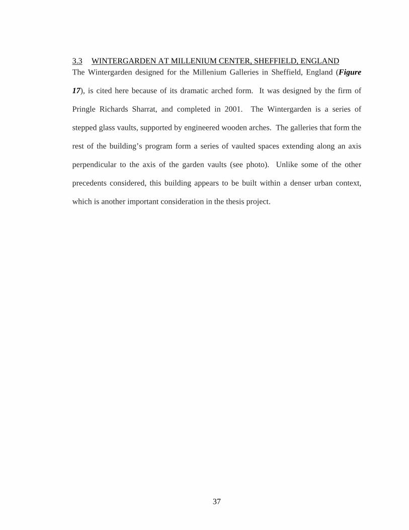
3.3 WINTERGARDEN AT MILLENIUM CENTER, SHEFFIELD, ENGLAND The Wintergarden designed for the Millenium Galleries in Sheffield, England (Figure
17), is cited here because of its dramatic arched form. It was designed by the firm of
Pringle Richards Sharrat, and completed in 2001. The Wintergarden is a series of
stepped glass vaults, supported by engineered wooden arches. The galleries that form the
rest of the building’s program form a series of vaulted spaces extending along an axis
perpendicular to the axis of the garden vaults (see photo). Unlike some of the other
precedents considered, this building appears to be built within a denser urban context,
which is another important consideration in the thesis project.

38
Figure 17 – Wintergarden of Millenium Galleries in Sheffield, England. The rest of the program is separate from the garden space in this case. One interesting aspect of this design is the stepped arch profile. This creates some interesting possibilities for the greenhouses to be included in the thesis program. Images copied from Reference 6

39
3.4 INSTITUTE FOR FORESTRY & NATURE RESEARCH, WAGENINGEN, NETHERLANDS
This building, designed by Behnisch, Behnisch & Partner and completed in 1998 6, is an
interesting precedent for two reasons. For one, It uses the plants to help cool the building
with natural ventilation; the two atrium spaces (see small plan in Figure 18) have been
described as ‘two green lungs’ 7. The figure includes a rough sketch of the natural
ventilation strategy. The other notable feature is the way the vegetation has been
integrated with the interior structure (far right side of Figure 18). It almost appears that
the building is an object inside the natural environment of the atrium, rather than being
the enclosing element. The use of cantilevered and suspended walkways allow the
occupants of the building to experience this indoor landscape without walking through
the planted floor of the atrium itself.

40
Figure 18 – Institute for Forestry and Nature Research, Wageningen, Netherlands. Like the South Burlington,VT facility, the building’s envelop and atrium roof is extensively glazed, but manages to avoid overheating, apparently through the use of natural ventilation, water and plants. It is also worth noting that the building occupants are barred from direct access to the atrium floor in order to protect the plants. Office windows and walkways allow the occupants to enjoy the garden without walking through it.

41
4 PROGRAM
4.1 DESCRIPTION OF PROGRAM ELEMENTS
1. GREENHOUSES
Daylit indoor spaces of different shapes and sizes, openness and intimacy,
placed in relation to the functional elements of the infrastructure in such a
way to inspire contemplation of the visitors role in the natural ecosystem.
They should derive a sense of connectedness with nature, a responsibility to
act in harmony with nature, and a sense of hope and joy that they CAN make
a difference at the local level in building a sustainable future. The
Greenhouse should be immediately accessible from the public entrance.
20,000 sq.ft. : Aerobic Treatment Tanks and Clarifiers, also known
collectively in the context of this thesis as the “Water Gardens”, This includes
sufficient spaces for circulation as part of guided and unguided tours.
8,000 sq.ft. : Decorative plantings, fountains, benches, open spaces.
*Not all 28,000 of this area needs to be housed in one building.
SUBTOTAL – 28,000 sq.ft.

42
2. MECHANICAL PLANT
10,000 sq.ft. : Closed Aerobic Tanks and Anoxic Tank (part of the tour).
1,000 sq.ft. : Centralized pumping machinery
500 sq.ft. : Electrical Inverter Equipment for Solar Array
250 sq.ft. : Engineer’s Office
200 sq.ft. : Central monitoring and control room
150 sq.ft. : Gallery of control room for tours.
75 sq. ft. : Single occupant unisex rest room.
5% = 600 sq. ft. total : Circulation spaces
SUBTOTAL – 12,775 sq.ft.
3. AUXILLARY SERVICES BUILDING
3000 sq. ft. : Solid Waste Recycling Center
(including temporary storage of recyclable materials, sorting facility, and
loading dock for transportation to final recycling facility).
4000 sq. ft. : Central Composting Center
(including temporary storage for community compostable material, facilities
for reducing appropriate material for addition to digestion stream, storage for
collected compost from community residences and sludge from Anaerobic

43
Reactor, facilities for transfer of compost to transport to nearest fertilizer
processing plant.)
SUBTOTAL – 7,000 sq.ft.
4. VISITOR CENTER
An environmental education center where visitors and students can learn
more about the system, its design, its operation, its goals and the implications
to future development. This space should be easily accessible from the public
entrance and provide immediate access to the tour route. It should be
connected visually to the Greenhouse.
1500 sq.ft. : Atrium / Reception
(includes indoor component of Polishing Wetland)
500 sq.ft. : Gallery Space
(for artwork and text which people can inspect at their leisure).
2000 sq.ft. : Auditorium
(where groups of up to 100 visitors can be shown videos and hear oral
presentations on the above subjects).
500 sq.ft. : Education Facility
(with computers that can be used by a relatively small number of individual
visitors to view materials related to environmental design, data related to the
operational state of the complex, etc.).
300 sq.ft. : Offices for education director and tour guides

44
(ideally the location of these offices would encourage daily interaction with
the maintenance staff)
500 sq.ft. : Storage and support spaces associated with education
(for exhibits, printed materials, copiers, etc.)
250 sq.ft. total : Restooms
SUBTOTAL – 5, 050 sq.ft.
5. OUTDOOR GARDEN
Outdoor paths that integrate the network of bioswales, the indoor spaces
described above, and the rest of the community. The goal here is to make the
infrastructure a positive part of peoples’ daily lives as they travel from home to
school, to the other recreational outdoor spaces (playgrounds, sports fields), to
work, to the store, to the Metro and so on.
2000 sq.ft. : Polishing Wetland (outdoor component)
300 sq.ft. : Fountain / Well.
1000 sq.ft. : Plaza
(with benches, plantings – should be immediately accessible to restaurants
and cafes occupying the ground floor of the apartments buildings on the
street)
6. OUTDOOR SERVICE SPACE
4000 sq.ft. : Anaerobic Digester

45
(preferably earth sheltered but with access points for maintenance)
7. BIOSWALES
There are no square footage requirements here. They consist of a broad
shallow ditch, with grasses planted along the bottom. Ideally, the swales
would be planted with bushes and trees that would beautify it, discourage
littering, discourage children from playing in it, and provide a refuge for
wildlife.
8. DISTRIBUTED POWER GRID
Each of buildings in the community will include photovoltaic arrays. Electric
energy from the panels will be converted to A/C power at the source and
connected to the local power grid. The energy will be distributed throughout
the local community. Ideally, any excess energy would be stored on-site for
use later, making the community self-sufficient. This part, at least, might be
foolish. As long as the existing electrical infrastructure does not require
upgrading to handle the power, it would be wiser to use it to distribute the
energy back to the entire municipal grid.
The design component of this thesis will include speculative designs for
integrating solar panels with the apartments and single-family residences.

46
As part of the sustainable community design, some of the single family
residences will be designed with composting toilets. The design implications
of this on the house and the community will be explored as part of the thesis
project as well.

47
4.2 AREA CALCULATIONS
Greenhouse * Aerobic Treatment Tanks and associated service spaces 20,000 Garden spaces 8,000 total 28,000 Mechanical Building Closed Aerobic Tank and Anoxic Tank 10,000 Pumping Equip 1,000 Inverters 500 Engineer's office 250 Control Room 200 Conrtol Room Gallery 150 Circulation 600 Restroom 75 total 12,775 Auxillary Services Building Recycling 3,000 Composting 4,000 total 7,000 Visitors Center Atrium 1,500 Gallery 500 Auditorium 2,000 Education Lab 500 Office 300 Restrooms 250 total 5,050 Garden (outdoor) Wetland 2,000 Fountain 300 Plaza 1,000 total 3,300 Outdoor Service Space total 4,000 grand total 60,125 total interior 52,825
* - Area calculations for the greenhouse are based on similar Living Machine™ systems built elsewhere, and on simple rules of thumb.

48
It is my goal to consider the entire life-cycle of the materials used in construction of the
building, from cradle to grave or, better, from ‘cradle to cradle’ (borrowing a phrase from
William McDonough). Because the design will not be defined to the point of
construction documents and bill of materials, this accounting will necessarily be more
qualitative, selecting materials that are recycled or sustainably harvested before
constructed, and recyclable / reusable / biodegradable when they are ultimately taken out
of service to this building.
5 DESIGN APPROACH
5.1 CONCEPTUAL DESIGN STRATEGIES
The basic design elements to be addressed in this thesis are:
1. Propose modifications to NCCI Master Plan to improve access to solar power
and to better integrate the built and natural environments (water flow,
pedestrian as well as vehicular traffic, etc.). Attempt to maintain the same
overall human population (density) as suggested by the Master Plan (about
4,000).
2. Conceptual design of rowhouses to accommodate solar energy collectors,
composting toilets, natural ventilation, under-house garage.
3. Conceptual design of apartment house to accommodate solar energy collectors,
natural ventilation, underground parking, etc.

49
4. Integration of street network, pedestrian paths, courtyards, and bioswales to
manage stormwater run-off.
5. Integration of NSRC building form(s) with its context (including landmarks
offsite) and the flows that it must manage and tap into.
6. Detailed design of the NSRC building(s), focusing on the integration of the
program elements, functional requirements, the architectural expression of the
building, its visionary and inspiration missions.
5.2 ALTERNATIVE SITE PARTIS
The main site planning issues include:
1. the creation of greenways for:
a. circulation (pedestrian and vehicles) through the neighborhood
b. establishment of formal relationships between buildings, streets and
landmarks
c. management of stormwater run-off
2. relationship of the NSRC building site to prominent landmarks on and off the
site and to the greenways.
3. working with the natural flows of energy and water within the site.
3. integrating the NSRC building with the life of the community (cafes,
restaurants, etc.).
4. creating a prominent entry space for the NSRC.

50
Figure 19 through Figure 22 show several sketches for alternative site strategies dealing
with the issues above. The different strategies share some common characteristics,
including broad greenways running north and south (some northwest to southeast) to
reflect the overall hydrology of the site. Each scheme uses these greenways and other
view corridors to create different hierarchical spaces and formal relationships between
them.
In each site diagram, the hatched areas on the north and east edges are considered to be
untouchable because of their historic significance. The lightly shaded areas in the middle
of the western boundary marks the location of the school and recreation center, which
will be assumed set. The arrows indicate major vehicular paths through and around the
site. They also define important relationships with the Metro station, Capitol Dome and
other landmarks in the larger community.

51
Figure 19 – Site Scheme 1: small urban squares anchor both ends of the single strong N-S axis defined by the bioswale. The NSRC engages the southern square on one side and North Capitol Street on the other. A small greenspace defines the natural connection between Mt Airy Church on North Capitol and the bioswale / greenway. This placement gives the NSRC a strong presence on K Street and North Capitol Street. The square on the north and the bioswale / greenway’s north terminus help ‘capture’ visitors approaching from the Metro station.

52
Figure 20 – Site Scheme 2: the bioswale / greenway weaves through the site, ending on a long green that connects to the NSRC. The NSRC addresses New Jersey Avenue and K Street, and is adjacent to the school, making its educational value more visible.

53
Figure 21 – Site Scheme 3: in this plan, the NSRC is sited on the north axis of the bioswale / greenway network. This gives it a much more direct connection to the greenway, fills a void in the fabric of the neighborhood (currently occupied by a swimming pool) and makes the facility much more of a gateway element to the community. On the other hand, the NSRC is now less visible from the major thoroughfares, and also puts it at a higher elevation than most of the rest of the neighborhood (which means that waste water would have to be pumped uphill). Minor axis greenways connect across the site as tributaries for stormwater runoff. This cross axis may tend to divide the community too much. The strong N-S axis is interesting here, but the drawbacks seem to override that.

54
Figure 22 – Site Scheme 4: this site strategy is similar to the others described above. It is distinct in siting the NSRC in the middle of the neighborhood rather than at the edge. This makes the building almost entirely the ‘property’ of the neighborhood, rather than a public attraction. It still offers the potential for a visual connection to the NAR LEED building south of the site along First Street. It also addresses the school diagonally. This semi-private site within the neighborhood may defeat some of the educational value of the building by making it hard for visitors to find. It appears that the strong north-south axial greenway with only minor tributary flow
channels, and some sort of strong cross axis (east-west) across the south of the site was
the most effective site plan. The NSRC might be located at either end of the major axes,
or at their intersection. It might also allow its form to extend out into the community
along these axes. These ideas are explored in more detail in the section below dealing
with building form.

55
5.3 BUILDING FORMS
Several alternative parti’s for the building form were explored. One functional
consideration that drives several of the forms is that the process of waste water treatment
involves a linear series of tanks, and that these tanks need access to sunlight. Several of
the schemes extend the greenhouses holding the tanks out into the landscape. Others
outline the more centralized parts of the building using the greenhouses . Still others
simply stack the greenhouses to create a more solid mass for the building. The forms
explored here are generally linear and not curved, although there is no reason that they
could not be.
One issue to be considered here is the surrounding context, which has not really been
defined as yet. Some of the sketches from the NCCI Master Plan given a conceptual
form to the buildings that might be built, but there is nothing sacred about these
conceptual sketches. Indeed, they will probably have to be modified to some extent for
solar power anyway. If there is a natural form to the NSRC that might inform the design
of the surrounding buildings, then that option should be explored. Additional analysis
into the connection between the NW1 buildings and the greater context of NOMA should
be undertaken. The historical context of the site and the sensibilities of the residents will
also have an impact.

56
I have come to favor the idea that some of the greenhouses can be distributed throughout
the neighborhood and provide point source water treatment. The remainder of the flows
will be handled at the NSRC.
57
6 DEVELOPMENT OF FINAL DESIGN
6.1 SITE DESIGN Continuing to work with the idea of using the constructed wetlands to reinforce axial
relationships across the site, I decided to create a network of parks that would connect
various entry points into the community and help visitors to discover the NSRC. This is
illustrated in Figure 23. The greenway running north and south, located on the east side
of the site is conceived of as a constructed wetland for handling stormwater, as is the
greenway running east and west and located near the south edge of the site. These public
greenways are connected to a series of private and semi-private garden spaces, including
rooftop gardens. The greenways are occupied by ‘lanterns’, which are actually
greenhouse structures for a distributed network of Living Machines™ (see Figure 24);
the round ‘lantern’ in the northwest corner is a water tower. The decision to distribute
half of the total water treatment function to machines throughout the community was
driven partly by this concept of creating markers, and partly by preliminary massing
studies that showed the NSRC beginning to overshadow its surrounding context (Mt
Airey Church) if all waste processing for the community was located in a single facility.

58
Figure 23 – Diagram of greenway network and how it is intended to connect entry points (gateways) to important elements of the community.

59
Figure 24 – Sketches of Living Machine ‘lanterns’ located throughout the community.
The constructed wetlands converge on the site for the NSRC, located in the southeast
corner of the site. These wetlands were designed to be compatible with DC’s urban
context (see Figure 25). The edges of the wetland were made absolutely straight and
lined by roads (the new L Street and Half Street ), creating a kind of grand boulevard.

60
Several sitting spaces line the edge of the wetlands also, providing locations for people to
interact with the natural beauty of the wetlands. There are grassy areas with a gradual
slope along the border for people to sit or walk. In addition to the cat tails, bulrushes and
other wetland species used to help filter the water, the wetlands would be strategically
enhanced by plantings of more ornamental native plant species that can help to ‘civilize’
the wetlands further. People are prevented (or at least discouraged) from walking
through the heart of the wetlands by low (3-4 ft walls) with plantings in front of them
(possibly including thorn bushes).
Figure 25 – Street section through E-W wetland.
From the greenspace network diagram and this concept for the wetlands, the full site plan
shown in Figure 26was generated. In addition to the greenways, wetlands, lantern and
NSRC, this plan gives a glimpse of the intent for solar power generation (the way the
rooftops are populated by solar arrays). The townhomes in the middle of the site have
been reordered to provide better solar access, not only for solar arrays, but for passive
solar heating and daylighting. Because the wetlands displaced some of the townhomes

61
proposed by the NCCI Waster Plan, I have added some mid-rise (3-5 story) apartment
buildings on the north and south edges of the site’s core in order to accommodate a
population similar to that suggested in the Master Plan (about 4000 people).
Figure 26 – Rendered Site Plan for the Community
(north is up in this plan, as with others incl. in this report)

62
6.2 BUILDING DESIGN The essential design goal for the Neighborhood Solar Regeneration Center (NSRC),
beyond meeting the requirements set forth in the program and accommodating the Living
Machines™, was to make the process of water purification clear to visitors (without
exposing them to anything too unappetizing). A secondary goal was to connect the
NSRC to the streetlife envisioned for the K St corridor.
The final design of the building elevates the garden (containing the living machine)
above the other program elements on heavy concrete columns. The garden is terraced
and steps down and around to form a loop (see Figure 27). Untreated waste is piped into
a settling tank under the plaza. The liquid is pumped up into the garden and then flows
down through the Living Machine™ and ends up back at the plaza, where it flows down
into a fountain basin in full view of passers by. During warm weather, the water is also
allowed to run from scuppers on the building’s western façade, where it is captured in a
basin and runs back to the plaza; this water feature is intended to help guide and draw
people from the street scene on K Street to the entrances of the building (see Figure 26).
From the plaza fountain basin, the water is pumped into the wetlands where it helps keep
the plants alive in times of drought, and there it is filtered further and allowed to soak into
the ground. The form of the terraces therefore reflects the cycle of water purification.
The entire terrace structure is contained within a separate enclosure that is solid below
(with window openings into the interior spaces) and translucent above. The glass top for
the garden is supported by a grid of street columns and trussed arches (Figure 28, Figure
29, Figure 31, and Figure 31). The glass is translucent rather than transparent in most

63
locations to help control solar heat gain in the summer. The glass roof of the building is
also covered with Built-In Photo-Voltaic (BIPV) cells. These small solar panels are
spaced to allow
Figure 27 – Basic configuration of the garden terraces that support the Living Machine™ and auxiliary components.
ample light to pass between them. They will help to create a dappled pattern of sunlight,
evoking the image of a canopy of trees. The power from these cells, as the leaves of a
tree, will provide a significant fraction of the power needed to operate the facility. The

64
corners of the box and the northern façade are transparent, allowing views into the garden
from strategic viewpoints along K Street and from the entry plaza at North Capitol Street.
The twin arched form of the roof (not identical twins) define the separation of upper and
lower terraces, and form a central valley that captures half of the rainwater from the roof
into a prominent downspout and scupper that create a dramatic presence on the building’s
west façade. The arched forms have a slightly industrial appearance to them, reflecting
the mechanical function of the building as well.
The skin below the level of the garden on the east, south and west sides is solid,
constructed from reinforced CMU with a layer of rigid insulation and a cultured stone
rainscreen on the outside. The rainscreen has a mottled terracotta finish, reflecting the
materials used in the Mt Airey Church nearby and reminiscent of industrial buildings of
the past.
The public procession begins at the plaza fountain where the wetlands intersect (the
northwest corner of the building. Visitors can walk up through the lightwell in the center
of the terraces, into the lower garden or up through the machine into the upper garden.
At both locations, there are spaces to sit and relax, enjoy a cup of coffee and a book, and
reflect on the surrounding garden. A stairway connects the upper and lower gardens,
forming a loop that parallels the flow of the water as it is purified. Catwalks with
translucent glass floorplates divide the upper and lower terraces, provide elevated views

65
Figure 28 – North Elevation of NSRC Building with context.
Figure 29- West Elevation of NSRC Building with context
66
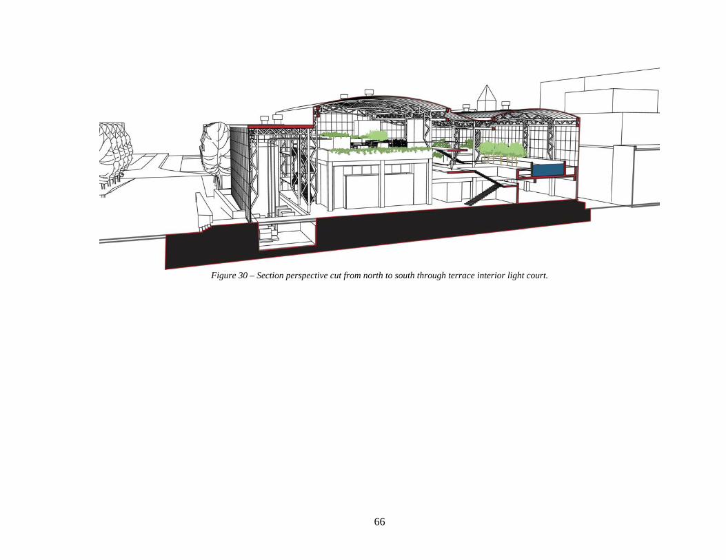
Figure 30 – Section perspective cut from north to south through terrace interior light court.

67
Figure 31 – Aerial View of the NSRC with context shown (ends of constructed wetlands are at left and bottom of this view)

68
of the garden, terminate on a bay that gives visitors a view of the wetlands to the west,
and also act as a path of emergency egress.
Figure 32 – Sketch of interior space showing the Lower Garden viewed from the Upper Terrace catwalk. The garden space will be mechanically ventilated to help keep it cool in the summer. In
the winter, much of the heating can be done by passive solar income, but the garden
space can also be heated through ducts in the raised floor of the garden. The garden will
not be air conditioned otherwise, but the other program spaces (the auditorium, education
lab, offices and service spaces ) can be. These areas will be separated from the
unconditioned space of the garden. It is likely that the garden space will be used by
people (other than visitors taking a tour of the facility) primarily in the fall, winter and
spring. It is easy to imagine hosting community functions and other gatherings in the
beauty of the indoor garden. In the summer, any outdoor space in Washington DC is

69
generally too warm and humid for most people to feel comfortable. Even so, the
conditioned spaces will still be useful for meetings and educational tours).

70
7 CONCLUSIONS In order to live more sustainably, it is important that begin to adopt a more sustainable
infrastructure, one that works in cooperation with nature. It is essential that people begin
to understand the infrastructure that sustains them and how their actions impact the
environment as well. This thesis project begins to explore the design issues involved
with integrating a decentralized, holistic and sustainable infrastructure into our urban
neighborhoods. It seeks ways to celebrate that infrastructure rather than making it
invisible. I do not claim to have answered all of the questions or solved the problems
associated with making such an infrastructure a reality, but I hope this project will help
start a discussion in the design community aimed at doing just that.
This project has proposed the creation of a largely self-sufficient energy and waste
treatment infrastructure within a community of approximately 50 acres, and with a
population of about 4000 residents. One of the first questions we should ask ourselves as
the discussion continues is ‘what is the minimum and maximum appropriate size of
community to apply this conceptual framework?’ The design proposed in this thesis
project created indoor garden spaces in close proximity to the Living Machine™ water
purification tanks, and sought to create a garden-like interior space. What other forms
can we envision to weave facilities such as this into our communities? What are the legal
and social issues involved? This is just the beginning of an exciting debate that will
include the general public, policy makers, engineers and, of course, architects. It is my
hope that this discussion will help lead us into a new era of technology and design
focused on living well, but within the capacity of the Earth to sustain us all.

A1
APPENDIX A – INTRODUCTION TO LIVING MACHINES™
Living Machines™ is a proprietary version of what some call ‘solar aquatic systems’.
There is nothing particularly proprietary about the basic technology and anyone can build
such a system if they have the experience. Living Machine™ systems are also marketed
under the company name Dharma Living Systems. Market research suggests that this is
the only company that has built waste water treatment plants for relatively large
commercial applications. Most of the other examples of this technology are used as
educational aids alone, built by teachers and their students.
Nearly all of the available literature on such systems is in reference to Living Machines™
installations, but most of the technical details on tank sizes, flow rates, plant species,
temperature, light and humidity levels, materials and so on appear to be considered trade
secrets of a sort. Repeated attempts to contact Dharma Living Systems for information
have failed thus far. By cross referencing several different papers, it has been possible to
establish some sizing guidelines for the systems – each 10,000 gallons per day of waste
water to be processed by the system requires approximately 1000 sq. ft. of floor area for
the tanks. In the paragraphs below, the basic idea behind the system, their physical form
and operating principals are discussed.
The basic configuration of the Living Machine™ is shown in below. Wastewater flows
through a series of cells or tanks, each performing a specific function.

A2
Figure 33 – Solar Aquatic (“Living Machine”) Schematic

A3
Anaerobic Reactor –
Untreated sewage flows into this tank, which is an airless, lightless environment.
Microbes breakdown the solids, reducing their mass by up to 75%. Ultimately, the
remaining solids need to be cleaned out periodically. These solids can be dried,
sterilized, composted and then used for fertilizer (if desired).5, 8
The liquid component of the waste is separated out and sent to the next tank in the
series.
Anoxic Reactor –
Promotes floc-forming and denitrifying microorganisms. Active (mechanical)
aeration of the liquid ensures that aerobic conditions exist in the reactor, as well as
assisting mixing of the fluid. 5, 8
This tank is generally closed at the top by a planted biofilter.
Closed Aerobic Reactor
Intended to reduce biochemical oxygen demand (BOD – a measure of the waste
levels remaining in the water) within the water to a low level, further remove
odorous gases and promote nitrification. 5, 8
The closed aerobic reactor is also covered by a planted biofilter. Active aeration is
also used here.

A4
Open Aerobic Reactor
Reduces BOD to better than secondary levels (clean non-potable water) and
completes the process of nitrification. 5, 8
These reactors have free-surface of water; plants are held by racks above the surface
of the water. Their roots help promote the purification process, filtering the water
and providing surface are where other agents can work. These tanks may host more
complex ecosystems including fish and snails.
Clarifier
This is essentially another settling tank where residual solid can settle out and be
sent back to the anoxic reactor (or digester) for continued processing.
The surface of the water is typically planted with duckweed to prevent algae
formation. 5, 8
Ecological Fluidized Bed
This tank provides final polishing of the waste water before it leaves the machine.
It is comprised of an annular bed of crushed rock through which the water is
circulated (typically by an air-lift pump). The rock media acts as a filter, and
provides surface area where microorganisms can attach and help consume the
remaining waste. A small amount of solid matter does collect in the bottom of the

A5
tank and must be removed periodically (to be processed along with the biosolids
from the anaerobic digester). 5, 8

REFERENCES
1 Schwartz, N., “A Neighborhood’s Story”, Voice of the Hill, March 2003, pp. 12-15. 2 Office of Deputy Mayor for Planning and Economic Development, “Northwest One Master Plan – Draft 11-11-05”, <http://dcbiz.dc.gov/dmped/cwp/view,a,1366,q,601471.asp> 3 Testimony of Ellen McCarthy, Director-Office of Planning, DC City Government Public Oversight Hearing on the Sursum Corda / Northwest One Redevelopment Project, November 16, 2005. 4 Adam J. Lewis Environmental Study Center – Oberlin College website – www.oberlin.edu/ajlc/ajlcHome.html 5 U.S. EPA, 2004, Wastewater Technology Fact Sheet – Living Machine. 6 Phaidon Atlas of Contemporary Architecture, Phaidon Press Inc., NewYork, 2004. 7 Steiner,F., “Natural Interferences”, Landscape Architecture, Vol. 90, No. 11, November 2000. 8 U.S. EPA, 2001. “The ‘Living Machine’ Wastewater Treatment Technology: An Evaluation of Performance and System Cost”. EPA 832-R-01-004.