Abstract - Spiral: Home · Web viewIn this work a robust hydrogel formulation was optimised for use...
27
Robocasting of Structural Ceramic Parts with Hydrogel Inks Ezra Feilden a,∗ , Esther García-Tuñón Blanca a , Finn Giuliani a , Eduardo Saiz a , Luc Vandeperre a a Centre of Advanced Structural Ceramics, Department of Materials, Imperial College London, SW7 2AZ, UK Corresponding Author; Centre of Advanced Structural Ceramics, ∗ Department of Materials, Imperial College London, SW7 2AZ, UK, Tel: +447815740963, Email: [email protected] Abstract Robocasting is a 3D printing technique that may be able to achieve the much-coveted goal of reliable, complex ceramic parts with low porosity and high strength. In this work a robust hydrogel formulation was optimised for use as the extrusion paste for robocasting. The paste’s rheological properties were characterised and the printing process was optimised with the aim of attaining dense monolithic ceramic parts. The pastes exhibit a characteristic shear thinning behaviour with yield stresses that can reach values above 1 kPa and depend mostly on their solid content and the particle size distribution. It is possible to formulate printable Al 2 O 3 and SiC inks with solid contents as high as 40 vol% that reached densities up to 95th% for SiC and 97th% for Al 2 O 3 with flexural strengths of 300 MPa and 230 MPa respectively after sintering. The sources of strength limiting defects are identified and related to the printing process. Keywords: Additive Manufacturing, 3D Printing, Robocasting, Ceramics, Rheology 1.Introduction In the last decade additive manufacturing (AM) has received a huge amount of attention from industry, academia and the public. It is already finding uses in a wide range of sectors due to the numerous
Transcript of Abstract - Spiral: Home · Web viewIn this work a robust hydrogel formulation was optimised for use...
Robocasting of Structural Ceramic Parts with Hydrogel InksEzra Feildena,∗, Esther García-Tuñón Blancaa, Finn Giuliania, Eduardo Saiza, Luc Vandeperrea
a Centre of Advanced Structural Ceramics, Department of Materials, Imperial College London, SW7 2AZ, UK
Corresponding Author; Centre of Advanced Structural Ceramics, Department of Materials,∗ Imperial College London, SW7 2AZ, UK, Tel: +447815740963, Email: [email protected]
Abstract
Robocasting is a 3D printing technique that may be able to achieve the much-coveted goal of reliable, complex ceramic parts with low porosity and high strength. In this work a robust hydrogel formulation was optimised for use as the extrusion paste for robocasting. The paste’s rheological properties were characterised and the printing process was optimised with the aim of attaining dense monolithic ceramic parts. The pastes exhibit a characteristic shear thinning behaviour with yield stresses that can reach values above 1 kPa and depend mostly on their solid content and the particle size distribution. It is possible to formulate printable Al2O3 and SiC inks with solid contents as high as 40 vol% that reached densities up to 95th% for SiC and 97th% for Al2O3 with flexural strengths of 300 MPa and 230 MPa respectively after sintering. The sources of strength limiting defects are identified and related to the printing process.
Keywords: Additive Manufacturing, 3D Printing, Robocasting, Ceramics, Rheology
1.Introduction
In the last decade additive manufacturing (AM) has received a huge amount of attention from industry, academia and the public. It is already finding uses in a wide range of sectors due to the numerous advantages it offers over traditional manufacturing methods for short production runs and complex shapes such as those in aerospace and biomedical engineering. Most work has been focused on printing polymeric and metallic materials, while ceramics have been developed less, partly due to their high melting points, which limit the applicable AM techniques to powder bed processes,[1,2] wet processes[3] and fused deposition of ceramics.[4]
Robocasting is a process that emerged as a distinct AM technique two decades ago.[5] It has been used to produce monolithic bodies and periodic lattices.[6] In a manner similar to fused deposition of ceramics, green 3D objects are built by extruding a filament of paste (known as an “ink”) through a fine nozzle while the nozzle’s position is controlled by a computer in accordance with a CAD model. Objects are built up in a layer-by-layer fashion, with the nozzle extruding ink in an appropriate pattern for each slice of a CAD model. As the object is built the extruded filament impinges on the printed part and fuses with it due to surface tension. Unlike fused deposition, robocasting relies on rheology rather than solidification in order to print a self-supporting part. This means there are no thermal gradients involved in robocasting, and the extrusion pressures are much smaller. Metallic[7], polymeric[8], graphene[9], bioactive[10], ferroelectric[11] and a wide range of ceramic[12] inks have all been successfully printed.
Clearly robocasting is a very flexible technique in the range of materials it can print, however it is somewhat limited in the shapes it can form. Parts will always have step edges due to the layerwise nature of manufacture, and supports must be printed to enable significant overhangs or large spanning elements.[13] The size of the step edges are defined by the radius of the printed filament, so are typically 100-250 m, while other techniques such as stereolithographyμ can achieve a fifth of that size. The real advantage of robocasting lies in the mechanical quality of the material produced and the flexibility of the technique to print different materials. Full densification of robocast parts has been readily demonstrated with conventional processing of the green parts.[14,15] Full densification has also been achieved with selective laser melting and binder jetting, however they required specialised modifications to the powder bed, subsequent isostatic pressing and very harsh sintering conditions.[1,2] Furthermore, functionally graded parts with complex, smooth compositional gradients have been printed in a manner that has yet to be reproduced by any other technique.[16,17]
The properties and composition of the ink are considered to be the most important factors in robocasting. Inks must be homogenous, free of air bubbles, have a high volume fraction of ceramic powder and the correct flow properties for extrusion while capable of holding their shape after printing. An ink must be highly shear thinning to allow extrusion through fine nozzles, and also retain a degree of strength and stiffness to be self-supporting following printing. This stiffness and strength equates to a large elastic component of the ink’s viscoelastic response. Aqueous inks are also preferred due to their simplicity, lower cost, low toxicity and slower drying, while low concentrations of organics are desired to allow fast burnout and high densities. Several approaches have been explored to meet each of these criteria, such as very high solids loading pastes which dry during printing,[5] polymer-solvent based inks which rely on the volatility of the solvent,[18] and colloidal ceramic suspensions where the particles interact by van der Waals forces to form a weak network.[19]
Recent work has explored inks based on a hydrogel which acts as a carrier for a ceramic powder.[10,20] The most common system explored so far is one based on Pluronic F-127. F-127 is a copolymer of polyethylene oxide and polypropylene oxide in a 2:1 ratio. The latter group can behave either in a hydrophobic or hydrophilic manner depending on the temperature and water content. The gelation is caused by hydrophobic association of the polymer[21] and can be controlled with temperature as it imparts thermally reversible behaviour. Inks can be made by mixing in ceramic powder, and no precise control of the pH is required. No additives are needed, so the ink preparation process is typically quick and easy compared to colloidal inks. Mixing is carried out when the ink is cold and the viscosity is lower. The ink is printed at room temperature when it is a weak, extrudable gel. Provided the volume fraction of the ceramic particles is not too high, interparticle interactions do not dominate the behaviour of the ink. Consequently this gel is compatible with any powder that can be made into an aqueous slurry.
While good densification of robocast parts has been sporadically reported for a number of materials,[12,14,15] reports of their mechanical properties are quite scarce in the literature, and no analysis of the reliability of monolithic bodies seems to have been completed. This is particularly important if robocasting is to be used industrially where defect distributions are key to understanding a part’s reliability. The present work aims to demonstrate mechanical properties of printed parts for both oxide and non-oxide ceramics, and to explore the limitations of the robocasting technique using inks based on a thermally reversible hydrogel. -Alα 2O3 was selected as the model oxide ceramic since this is one of the most used ceramics in AM. Liquid phase sintered -SiC was taken as the model non-oxide material, in part to illustrate the powerα of the hydrogel inks in yielding inks for mixtures of powders with very different charging
behaviour in water. Moreover, these materials are representative of two large families of structural ceramics in terms of processing, properties and applications.
2.Experimental
Fine alumina powder (SMA6, Baikowski, FR) with a d(0.5) of 0.3 m was sieved to 100μ m toμ remove large agglomerates. -Silicon carbide powder (UF-25, H.C. Starck, DE) with a d(0.5) ofα 0.45 m was mixed with 6μ wt% alumina (SMA6, Baikowski, FR) and 4 wt% yttria (Grade-C, H.C. Starck, DE) sintering aids[22] in methanol for 24 hours with Si3N4 milling media in a roll mill, followed by drying in a rotary evaporator.
Particle size distributions were measured by Dynamic Light Scattering in a Mastersizer 2000 using 2 minute scans. The results reported are the average over 3 scans.
A Pluronic stock solution was made by stirring Pluronic F-127 powder (Sigma-Aldrich, UK) into a flask of deionised water at 4 °C until a 25 wt% solution is obtained. This solution was then mixed in a Thinky ARE-250 planetary mixer at 2000 RPM for 1 minute. The solution was left in a refrigerator at 4 °C for 24 hours, allowing bubbles to dissipate. The ceramic powders were then added to this stock solution in a stepwise manner to prepare inks with various solids loadings. Three steps consisting of two mixes at 2000 RPM for 1 minute followed by cooling to 0 °C and stirring were found to be sufficient to break agglomerates and give inks which appeared smooth and homogenous. The inks were then cooled and defoamed for 2 minutes at 2200 RPM, before finally loading the inks in 3 cm3 syringe barrels ready for printing.
Rheological measurements of the inks were carried out on a TA Instruments Discovery HR-1 rheometer with a 40mm parallel plate geometry, a 1 mm gap and a solvent trap to prevent drying. Flow ramps were conducted at strain rates of 0.02-200 s-1. Dynamic mechanical analysis (DMA) was carried out at 1 Hz, varying the oscillation stress from 0.1 to 3000 Pa. The phase lag ( ) between peak shear stress and peak shear strain was determined automatically by theδ equipment’s software averaging over 10 oscillations. Yield stresses were calculated by observing the stress at which the storage modulus (G’) is equal to the loss modulus (G’’) during DMA. Flow curves were generated by extruding syringes of ink with a Zwick iLine mechanical testing machine. A custom frame was used to allow the machine to apply a constant displacement rate to the plunger of the syringe of ink. This rate was chosen such that the ink is extruded at 10 mm/s, determined by the extrusion ratio.
Aerobasic G-code was used to design the tool path to create the raster patterns of each layer for each orientation, with the raster path running parallel or perpendicular to the long axis of the bar for the “lengthwise” and “widthwise” parts respectively. Conical nozzles of an internal diameter of 200 m were used to print all parts in this work. The G-code was visualised withμ RoboCAD (3dInks, USA). Printing was carried out on a robocaster system (3dInks, USA) onto polytetrafluoroethylene substrates. A 40 mm dummy line (known as the “lead-in”) was printed immediately before the start of each part to ensure flow is homogenous as the part is printed. Forty 40x3x2 mm test bars were printed for each material. The temperature and humidity of the whole system was controlled by a custom built enclosure and a convection heater set to 23 °C while the measured humidity varied from 65-85%.
Printed parts were dried for 24 hours in a convection oven at 37 °C. De-binding was achieved by heating for 2 hours at 600 °C in air. This temperature was chosen as TGA analysis indicated it was sufficient to burn out the polymer without significantly oxidising the SiC. Alumina parts
were pressureless sintered at 1550 °C for one hour in air. Silicon carbide parts were pressureless sintered at 2050 °C for one hour in a graphite furnace under an argon atmosphere at 1 bar pressure. A powder bed of the same composition as the parts was used to reduce the evaporative loss of sintering additives. All heating and cooling rates were 5 ° per minute.[23]
Densities were measured by the Archimedes method. Average grain size was calculated by analysing SEM images of etched surfaces with the cell counter plugin in ImageJ. Mechanical testing consisted of 4 point bending in accordance with ASTM C1161–13 on samples measuring 40 by 3 by 2 mm polished to 1 m on one side.μ [24] A 20 mm bottom span and a 10 mm top span was used on a Zwick iLine universal testing machine. Testing was carried out with a displacement rate of 0.2 mm min-1 and with the polished surface in tension. Hardness was measured using a diamond Vickers tip on an Indentec 6030LKV with a load of 5 Kg. Indent sizes were measured by optical microscopy. Microstructures were examined after grinding and polishing with diamond suspension down to 1 m followed by coating with gold and imagingμ with secondary electrons in a JEOL JSM-6010 SEM at 20 kV.
3.Results and Discussion
3.1 Rheology and Ink Formulations
The ink’s and gel’s flow properties can be approximated by the Herschel-Bulkley model[25];
τ=τ y+K γ̇n (1)
where K is the viscosity parameter and n is the shear thinning coefficient. All of our inks and
gels exhibited a yield stress (τ y>0) and were shear thinning at stresses above the yield stress
(0<n<1). A typical flow test is shown in Fig. 1a. The exponential decrease in viscosity as shear rate increases demonstrates the shear thinning behaviour.
The gelation behaviour of a Pluronic gel is demonstrated in Fig. 1b. An increase in viscosity by two orders of magnitude occurs at the gelation temperature of ~17.5 °C. Above 23 °C the viscosity remains relatively unchanged, so this was chosen as the ambient enclosure temperature. The yielding behaviour of the gel is shown in Fig. 1c. At low stress the gel exhibits a linear viscoelastic response. As the stress amplitude is increased G’ falls and G’’ rises until G’=G’’, indicating the yield stress of the gel. This can be measured more directly using flow ramps, but this method is significantly slower and tended to show much more scatter. The yield stress and stiffness of a 1 part Pluronic, 3 parts water gel at 23 °C was found to be 261±45 Pa and 15±3 kPa respectively.
Printable ceramic inks were created by adding 30-40 vol% of ceramic powder to this gel. At volume fractions of ceramic powder below 30%, densification during sintering was difficult due to low green densities and drying cracks, while volume fractions above 45% exhibited prohibitively high viscosity and poor printability. The rheological properties of five compositions each for SiC based and Al2O3 based inks ranging from 0-48 vol% for SiC and 0-39 vol% for Al2O3 were tested. The inks exhibited a similar elastic and yielding behaviour to the Pluronic gels, as demonstrated in Fig. 1c, however G’, G’’, τ y and η were all larger in the inks with ceramic powder.
The larger G’ and G’’ can be attributed to the formation of a stiff network of particle interactions. This is supported by the fact that these parameters fall when 0.5 wt% Dolapix CA is added to alumina inks, seen in Fig. 2. The Dolapix adsorbs to the particle’s surfaces and provides
electrosteric stabilisation, greatly reducing interactions between the particles, preventing them from forming agglomerates or a rigid network, and moving the isoelectric point of the powder away from the pH of the ink (pH~7). Similar effects governed by the interparticle interactions have been seen in colloidal inks, which exhibit G’ from 30-150 kPa.[19]
On the other hand τ y is virtually unchanged by the dispersion and composition of the ceramic
powder, as seen in Fig. 3. This is in contrast with colloidal inks where τ y can vary by an order of magnitude by controlling the surface interactions.[19] In hydrogel inks however the majority of the strength comes from the polymer gel which acts as a carrier for the particles, in a similar manner to ceramic-polymer suspensions used in injection moulding, reaching yield strengths up to 2 kPa. The τ y of the Pluronic gel is an order of magnitude larger than the τ y exhibited by interparticle interactions in colloidal inks, so the effect of these interactions is drowned out by the strength of the Pluronic gel. The increase of τ y with particle volume fraction can be attributed to the fact that the flow of the hydrogel is constricted by the presence of the ceramic particles that share some of the load, so a larger overall stress is required to instigate flow. This effect has been reported for ceramic injection moulding systems[26] and can be fit with a modified Krieger-Dougherty model[27];
τ yτ yp
=(1− φφm )
−2.5φm
(2)
where φ is the volume fraction, φm is the volume fraction where the yield stress tends towards infinity and indicates the absolute limit for the ceramic loading (0.69 for these hydrogel-based inks), and τ yp is the yield strength of the Pluronic gel.φm is thought to vary with the particle size distribution, so in principle this value should differ between the SiC and Al2O3 inks, however any differences this imparted on the yield strength were too small to measure in our case.
Other rheological properties of the hydrogel inks developed here are comparable to alternative ink systems reported. Compared to colloidal inks, the hydrogel inks have similar shear thinning coefficients (n = 0.1-0.2), a similar range of G’s (100-3000 kPa), lower useful ceramic volume fractions (0.3-0.45) and somewhat larger viscosity parameters (K = 2-6 kPa). In hydrogel inks the dominant shear thinning mechanism comes from the disruption and breakdown of the hydrogel network under shear stress. As the gel is stressed above τ y, G’ sharply falls due to the reversible breakup of the bonds which constitute the Pluronic network. The initial rise in G’’ is due to partial yielding, increasing the internal friction of the material, as the losses (tan ) areδ defined by G’/G’’. Beyond the yield point the viscosity of the material falls due to its shear thinning properties, so G’’ also falls. The losses as a percentage of power input continue to increase as the material is increasingly less elastic, but the absolute value of losses peaks at the yield point. When the stress is removed the Pluronic network immediately reforms. This shear thinning behaviour also facilitates the formation of a smooth filament without any die swell when the ink is extruded. A yield stress is needed such that the printed material maintains its shape after exiting the nozzle and the lower printed layers of a part can support the weight of the layers above them. A τ y of 200 Pa is large enough to print tall simple parts, so the Pluronic gel is printable with or without the addition of ceramic powder.
An ideal ink has high stiffness (G’), high volume fraction of ceramics and high yield strength (τ y), but also a low value for n indicating strong shear thinning and a low viscosity parameter (K). A compromise must be found where the ink is made as stiff and strong as possible while still being mixable and printable below the maximum extrusion pressure of the printer and capable of fusing with earlier printed layers. For printing monolithic parts the high volume fraction is of

particular importance to reduce cracks from drying shrinkage and porosity after sintering, while for printing lattices the stiffness is of additional importance as it reduces sagging of suspended struts.
Fig. 1d indicates schematically how the volume fraction of solids and the temperature affect whether the ink can be extruded during printing. Altering the particle size distribution of the ceramic powder can alter the printable window, with wider size distributions allowing better packing hence higher volume fractions. This is demonstrated in the SiC inks which have a bimodal size distribution due to the oxide additives.[28]
3.2 Printing Parameters
The main controllable printing parameters were print speed, raster pattern, rod spacing and nozzle size. In general faster printing speed is preferable as it reduces the time to build a part and can facilitate more stable flow. Extrusion testing of inks as seen in Fig. 4 found stable flow in the range 2.5-20 mm/s. On the other hand, high printing speeds reduce the accuracy of the tool path when changing direction and cause sharp corners to become rounded. In this work 10 mm s-1 was found to be suitable in all cases.
The raster pattern to fill in the part was chosen to minimise the amount of space between the filaments during printing. The closest packed structure is a hexagonal layup of filaments, shown in Fig. 5, so this was chosen for all parts. The rod spacing between the filaments needs to be sufficiently small to cause the filaments to completely squeeze together during printing, but not so small as to cause overfill of the area being printed. This was empirically found to be d/1.2, where d is the diameter of the nozzle. A layer height of d/1.15 was chosen to give appropriate hexagonal stacking of the filaments. For the squeezing process to produce a good interface between adjacent filaments the extruded filaments have to be reasonably smooth when exiting the nozzle. If the filament’s surface is macroscopically rough then small pockets of air can become trapped between filaments, leaving defects after sintering.
The 200 m conical tip was chosen as it allowed 100 m resolution and printing times of 5-10μ μ minutes per bar. The conical shape also lowered the printing pressure required compared to cylindrical tips. Tips up to 1540 m and down to 100μ m were successfully used, however theμ dimensional accuracy of the larger tips was poor and the large pressure required for the smaller tip was close to the maximum force of the printer.
In other work in the literature scaffolds were printed in an oil bath to allow better control over drying and temperature, however for printing of monolithic parts the oil environment was found to leave periodic, inter-rod defects (see Fig. 6). This is likely due to the oil being trapped between adjacent filaments as they are squeezed together. This leaves very large voids after burnout which limit strength greatly. Thus all of our successful samples were printed in air at >65% humidity. This allowed drying to take place independently after printing had finished. Drying cracks were frequently observed if the drying rate was too fast or the part did not detach from the substrate adequately. This was mitigated by ensuring the substrate is highly polished. Using these parameters it was possible to print a range of geometries including arbitrary CAD files and scaffolds. A selection of these are shown in Fig. 7.
3.3 Mechanical Properties
Green alumina parts were found to sinter to 97±1% density retaining an average grain size of 1.40 m. Fig. 8 shows residual porosity at triple points and inside grains. These pores were <2μ
m in diameter. Silicon carbide parts reached 95±1.5% density during sintering, which isμ

comparable to robocast silicon carbide in other work.[29] The average grain size was 4.38 mμ however the microstructure is dominated by few plate-like grains over 20 m in length.μ Porosity tended to be localised to silicon carbide grain boundaries isolated from the yttria-alumina rich phase, and was typically <15 m in diameter. This second phase was identified asμ yttium aluminate monoclinic using XRD, see Fig. 9, and is in close agreement with other spectra reported in the literature of liquid phase sintered SiC processed at similar temperatures.[30]
Weibull analysis of robocast parts has only been completed for lattices in the literature.[31,32] The mean strengths and Weibull moduli of our monolithic samples of each material printed in each orientation are summarised in Table 1, alongside data for a set of unpolished parts. The SiC samples exhibited a mix of intergranular and transgranular fracture, while the Al2O3 samples failed intergranularly. The strength data, shown in Fig. 10 and Table 1, are comparable to the strength of equivalent commercially available SiC and Al2O3.[33,34] Hardness was found to be 18.6±0.8 GPa for Al2O3 and 23.4±2 GPa for SiC. The toughness was estimated from measuring the radial crack lengths from these indents,[35] and gave a value of 3.31±0.23 MPa√m for Al2O3
and 3.11±0.17 MPa√m for SiC, again, roughly comparable to commercially available material. The Weibull moduli are in agreement with those of robocast scaffolds which range from 3-9[31] although the moduli were somewhat lower for the samples printed in the widthwise an heightwise directions. Consequently, when designing tool paths to print ceramic parts our data show that greater strength and reliability can be achieved when critical areas are rastered in the direction parallel to the expected force lines.
While the strength and reliability of our printed material is acceptable for many applications, defects must be limiting these properties. From the Griffith criterion the average critical defect size was calculated as 50 m in Alμ 2O3 parts and 25 m in SiC parts. From smallest to largest, fourμ possible defects were identified: (1)- Residual pores after sintering. These are the critical defects in the lengthwise SiC samples due to the difficulties densifying this material without pressure. (2)- Bubbles/ agglomerates/ contamination in the ink. Effective defoaming and mixing reduced these defects greatly, however they cannot be completely ruled out, and are the most likely strength limiting defect in the lengthwise Al2O3 samples. (3)- Air trapped between filaments during printing. The filaments of ink were found to bond together very well during printing; the interface was not visible after sintering and grains were found to readily grow across where the interface would have been, as seen in Fig. 11. However this is the only defect which would strongly depend on the printing direction, and thus they must be present in both materials to account for the anisotropy of the Weibull modulus observed. This is identified as the main critical defect in all widthwise and heightwise parts. (4)- Surface defects. As with parts produced by virtually all AM techniques, as there will always be step edges associated with the layer-by-layer nature of how parts are printed, seen on the sides of the bars in Fig. 8. Printing through ever smaller tips reduces their size (as they are roughly as large as the tip radius), however this greatly increases built time and pressure drop to levels unfeasible for high volume fraction inks. Thus the surface finish is an important source of defects. The substrate that the part is printed onto may also play a role, as the roughness of the substrate is imprinted onto the bottom of the part. If the roughness is larger than the critical defect size then this too will limit strength. These issues were overcome by the polishing prescribed by ASTM C1161–13. As seen in table 1 the strength and reliability of the unpolished parts was very low, thus surface finishing is necessary when using this technique.
4.Conclusions
Simple, flexible and robust inks for the robocasting of ceramic parts were formulated based on a hydrogel. The inks exhibit shear thinning behaviour, their storage modulus is comparable to those based on colloidal suspensions, their yield stresses are higher, and their ceramic volume fraction is slightly lower. This approach has been used to print simple three-dimensional SiC and Al2O3 parts that achieved near full density and average strengths of 300 MPa and 230 MPa after sintering. Defects resulting from the printing process limit the mechanical strength in many cases depending on the orientation of the part with respect to printing direction. This results in an anisotropic Weibull modulus and strength in each material.
5.Acknowledgments
The authors would like to thank the industrial consortium of the Centre of Advanced Structural Ceramics at Imperial College London which includes Rolls-Royce Plc, Morgan Advanced Materials Plc, Reaction Engines Ltd, Defence Science and Technology Laboratory, Asahi Glass Ltd, and Kerneos Inc., and the Engineering and Physical Sciences Research Council for the funding of this work.
6.References
[1] Yoo J, Cima MJ, Khanuja S, Sachs EM. Structural ceramic components by 3D printing. Solid Free Fabr Symp 1995:479–88.
[2] Wilkes J, Hagedorn Y-C, Meiners W, Konrad W. Additive manufacturing of ZrO2 Al2O3 ceramic components by selective laser melting. Rapid Prototyp J 2013;19:51–7.
[3] Cappi B, Özkol E, Ebert J, Telle R. Direct inkjet printing of Si3N4: Characterization of ink, green bodies and microstructure. J Eur Ceram Soc 2008;28:2625–8.
[4] Onagoruwa S, Bose S, Bandyopadhyay A. Fused deposition of ceramics (FDC) and composites. Solid Free. Fabr. Symp., 2001, p. 224–31.
[5] Cesarano J. A Review of Robocasting Technology. Mater Res Soc Symp Proc 1999.
[6] Lewis JA, Smay JE, Stuecker JN, Cesarano J. Direct Ink Writing of Three-Dimensional Ceramic Structures. J Am Ceram Soc 2006;89:3599–609.
[7] He G, Hirschfeld DA. Robocasting and Cofiring of Functionally Graded Si3N4-W Materials. 25th Annu. Conf. Compos. Adv. Ceram. Mater. Struct., 2001.
[8] Ghosh S, Parker ST, Wang X, Kaplan DL, Lewis JA. Direct Write Assembly of Microperiodic Silk Fibroin Scaffolds for Tissue Engineering Applications. Adv Funct Mater 2008;18:1883–9.
[9] García-Tuñon E, Barg S, Franco J, Bell R, Eslava S, D’Elia E, et al. Printing in Three Dimensions with Graphene. Adv Mater 2015;27:1688–93.
[10] Franco J, Hunger P, Launey ME, Tomsia AP, Saiz E. Direct write assembly of calcium phosphate scaffolds using a water-based hydrogel. Acta Biomater 2010;6:218–28.
[11] Tuttle BA, Smay JE, Cesarano J, Voigt JA, Scofield TW, Olson WR, et al. Robocast Pb(Zr0.95Ti0.05)O3 Ceramic Monoliths and Composites. J Am Ceram Soc 2001;74:872–4.
[12] Cesarano J. Robocasting: Direct fabrication of ceramics from colloidal suspensions. Proc. Solid Free. Fabr. Symp., 1997, p. 25–36.
[13] Gratson GM, Xu M, Lewis JA. Direct Writing of Three-Dimensional Webs. Nature 2004;428:2481.
[14] Hirschfeld DA, Stuecker JN, Cesarano J, He GP. Robocasting and Mechanical Testing of Aqueous Silicon Nitride Slurries 2000:8
[15] Denham HB, Cesarano J, King BH, Calvert P. Mechanical behavior of robocast alumina. Proc. Solid Free. Fabr. Symp., Albuquerque, NM, and Livermore, CA (United States): 1998, p. 589–96.
[16] Hardin JO, Ober TJ, Valentine AD, Lewis JA. Microfluidic Printheads for Multimaterial 3D Printing of Viscoelastic Inks. Adv Mater 2015;27:3279–84.
[17] Cesarano J, King BH, Denham HB. Recent Developments in Robocasting of Ceramics and Multimaterial Deposition. Proc. Solid Free. Fabr. Symp., 1998.
[18] Lu X, Lee Y, Yang S, Hao Y, Evans JRG, Parini CG. Solvent-based paste extrusion solid freeforming. J Eur Ceram Soc 2010;30:1–10.
[19] Smay JE, Joseph C, Lewis JA. Colloidal Inks for Directed Assembly of 3-D Periodic Structures. Langmuir 2002;84:5429–37.
[20] Fu Q, Saiz E, Tomsia AP. Direct ink writing of highly porous and strong glass scaffolds for load-bearing bone defects repair and regeneration. Acta Biomater 2011;7:3547–54.
[21] Vadnere M, Amidon G, Lindenbaum S, Haslam J. Thermodynamic studies on the gel-sol transition of some pluronic polyols. Int J Pharm 1984;22:207–18.
[22] She JH, Ueno K. Densification behavior and mechanical properties of pressureless-sintered silicon carbide ceramics with alumina and yttria additions. Mater Chem Phys 1999;59:139–42.
[23] Baud S, Thevenot F, Pisch A, Chatillon C. High temperature sintering of SiC with oxide additives: I. Analysis in the SiC-Al2O3 and SiC-Al2O3-Y2O3 systems. J Eur Ceram Soc 2003;23:1–8.
[24] ASTM C1161-13, Standard Test Method for Flexural Strength of Advanced Ceramics at Ambient Temperature, ASTM International, West Conshohocken, PA, 2013, www.astm.org
[25] Herschel WH, Bulkley R. Konsistenzmessungen von Gummi-Benzollosungen. Kolloid-Zeitschrift 1926;39:291–300.
[26] Edirisinghe MJ, Shaw HM, Tomkins KL. Flow behaviour of ceramic injection moulding suspensions. Ceram Int 1992;18:193–200.
[27] Krieger IM, Dougherty TJ. A Mechanism for Non-Newtonian Flow in Suspensions of Rigid Spheres. J Rheol (N Y N Y) 1959;3:137.
[28] Chen ZC. Effect of particle packing on extrusion behavior of pastes. J Mater Sci 2000;35:5301–7.
[29] Cai K-P, Román-Manso B, Smay JE, Zhou J, Osendi MI, Belmonte M, et al. Geometrically Complex Silicon Carbide Structures Fabricated by Robocasting. J Am Ceram Soc 2012;95:2660–6.
[30] Magnani G, Beaulardi L, Pilotti L. Properties of liquid phase pressureless sintered silicon
carbide obtained without sintering bed. J Eur Ceram Soc 2005;25:1619–27.
[31] Miranda P, Pajares A, Saiz E, Tomsia AP, Guiberteau F. Mechanical properties of calcium phosphate scaffolds fabricated by robocasting. J Biomed Mater Res - Part A 2008;85:218–27.
[32] Genet M, Houmard M, Eslava S, Saiz E, Tomsia AP. A two-scale Weibull approach to the failure of porous ceramic structures made by robocasting: possibilities and limits. J Eur Ceram Soc 2013;33:679–88.
[33] Munro RG. Material Properties of a Sintered -SiC. J Phys Chem Ref Data 1997;26:1195–α201.
[34] Munro RG. Evaluated Material Properties for a Sintered Alpha -Alumina. J Am Ceram Soc 1997;80:1919–28.
[35] Lawn BR, Evans AG, Marshall DB. Elastic/Plastic Indentation Damage in Ceramics: The Median/Radial Crack System. J Am Ceram Soc 1980;63.
Figures
Figure 1- a- Flow ramps of Al2O3 and SiC inks compared to the stock gel demonstrating extensive shear thinning behaviour and the somewhat higher viscosity of the particle laden gels. b- Viscosity temperature sweep of the F127
showing the reversible gellation between 10-20°C. c- DMA of the hydrogel gel and SiC and Al2O3 inks at 1Hz demonstrating the transition out of the linear viscoelastic region due to the disruption of the gel network at stresses near
and above the yield point. The yield point is defined to be the stress where the G’=G’’ and the stiffness is the G’ when <<τ τy. Storage moduli in filled shapes, loss moduli in open shapes. 39vol% SiC inks in red circles, 36vol% Al2O3 inks in
blue triangles, Pluronic gel without particles in black squares. d- Estimated viability map of different inks printing at different temperatures incorporating the major limiting effects during printing. The SiC and Al2O3 inks used for printing
are marked. Boundaries between regions are not sharp and depend on the particle size distribution of the ceramic powder. Measurements carried out at 23°C unless otherwise indicated.
Figure 2- a-Flow ramp 37.5 vol% Al2O3 inks with and without 0.5 wt% dolapix. The decrease in viscosity with increasing shear rate is due to the shear thinning nature of the Pluronic. The stabilised inks exhibit a large decrease in viscosity
compared to the unstabilised inks. b- DMA of the stabilised and unstabilised 37.5 vol% Al2O3 inks showing the very large difference in G’ between the two.

Figure 3- a- Plots of storage modulus in the linear viscoelastic region against volume fraction of ceramic particles for SiC-Pluronic, Al2O3-Pluronic and Dispersed Al2O3-Pluronic inks. b- Plots of the yield strength against volume fraction for
the three ink systems with a Kreiger-Dougherty fit.
Figure 4- Flow curves for printing at different speeds through a 200 m tip and a macro photograph of the tip duringμ extrusion showing the lack of die swell. Stable flow from 2.5-20 mm/s is demonstrated, indicating a homogenous ink.

Figure 5- Schematics showing the tool path used to create the lengthwise (left) and widthwise (middle) and heightwise (right) printing orientations from an end view and isometric view.

Figure 6- Fracture surfaces of green SiC bars in the widthwise orientation printed under mineral oil (a) and in air (b) showing the voids running from side to side when printing under oil which are not present when printing in air.

Figure 7- Macro photo showing sintered SiC and Al2O3 scaffolds, parts and test bars printed using the hydrogel inks.
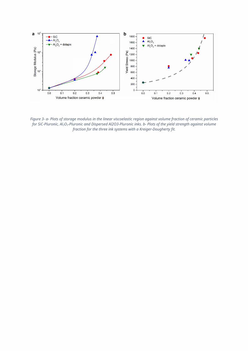
Figure 8- Fracture surfaces (top and middle) and polished microstructure (bottom) of Al2O3 (left) and SiC (right) lengthwise bars showing the porosity and grain structure. In the SiC the S marks the -SiC phase and the L marks theα
yttria-alumina rich phase.

Figure 92- XRD spectra of the SiC part showing peaks associated with the SiC and peaks identified as yttrium aluminate monoclinic (YAM).
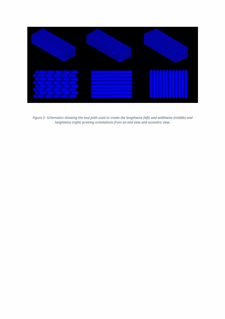
Figure 10- Probability of failure distributions in 4-point bend testing of Al2O3 and SiC printed in the lengthwise, widthwise and heightwise orientations.
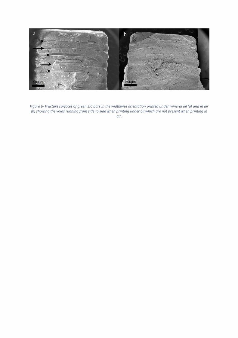
Figure 113- SEM image of the edge of a SiC bar with a printing layer marked. The layer is not visible inside the part and grains are seen to grow across the boundary, indicating good adhesion between the rods during printing.
Table 1- Strengths and Weibull moduli of each material printed in each orientation.
m σ0 (MPa) Average Strength (MPa)SiC lengthwise 6.1 377
305±60SiC widthwise 4.4 378SiC heightwise 3.8 242
Al2O3 lengthwise 8.9 297232±27Al2O3 widthwise 4.8 265
Al2O3 heightwise 3.0 220Al2O3 lengthwise, No Polishing 1.7 214 170±117