
Abstract I made this final thesis in the planning section ...
73
Engineering Typical Schedule Pag. 1 Abstract I made this final thesis in the planning section of Saipem, an engineering company specialized in the Oil& Gas industry. In this competitive business, planning team is a key element of the project. Indeed, price, technical solution and lead time are the decisive factors to win a project. In execution phase, planning team must highlight to key project’s managers critical points and control progress, so that the effective duration of the project is consistent with the contractual duration. The main objective of this thesis is to realize a typical schedule of engineering for an onshore plant. This typical schedule must be a referent tool for planning engineers working on a real project. This document must contain: an exhaustive list of engineering activities, a typical codification for engineering activities, and, the most important, typical logic sequences of engineering. To fulfill this objective, I first had to study engineering, then I had to learn how to use “Primavera P6” - project management software - and I finally had to merge those skills to realize the “Engineering Typical Schedule”. To study engineering, I had to understand the breakdown structure of this phase of the project, to understand technical content of main engineering activities, to identify inputs and outputs of these activities and their relationships. After implementation of the schedule into “Primavera P6”, I had to analyse the schedule I did to correct it, to make it consistent, and to strengthen the credibility of this document. The result of my internship is a typical schedule designed to make easy its use by planning engineers on a real project. I made a typical structure compliant with engineering organization in Saipem and I grouped sequences of activities into typical sequences to put a special emphasis on main logics of engineering. Besides, I worked on a “Handbook for planning engineers” and add many comments on the schedule so that it can be considered as a training tool for junior planning engineers as well. To conclude, I am very satisfied with this professional experience. I think I have reached the target and made an efficient tool for Saipem. Besides, I gained specific project control knowledge thanks to my final thesis supervisor, Mr Olivier Nègre, head of planning section for Saipem.
Transcript of Abstract I made this final thesis in the planning section ...

Engineering Typical Schedule Pag. 1
Abstract
I made this final thesis in the planning section of Saipem, an engineering company specialized in the
Oil& Gas industry. In this competitive business, planning team is a key element of the project. Indeed,
price, technical solution and lead time are the decisive factors to win a project. In execution phase,
planning team must highlight to key project’s managers critical points and control progress, so that the
effective duration of the project is consistent with the contractual duration.
The main objective of this thesis is to realize a typical schedule of engineering for an onshore plant.
This typical schedule must be a referent tool for planning engineers working on a real project. This
document must contain: an exhaustive list of engineering activities, a typical codification for
engineering activities, and, the most important, typical logic sequences of engineering.
To fulfill this objective, I first had to study engineering, then I had to learn how to use “Primavera P6” -
project management software - and I finally had to merge those skills to realize the “Engineering
Typical Schedule”. To study engineering, I had to understand the breakdown structure of this phase of
the project, to understand technical content of main engineering activities, to identify inputs and
outputs of these activities and their relationships. After implementation of the schedule into “Primavera
P6”, I had to analyse the schedule I did to correct it, to make it consistent, and to strengthen the
credibility of this document.
The result of my internship is a typical schedule designed to make easy its use by planning engineers
on a real project. I made a typical structure compliant with engineering organization in Saipem and I
grouped sequences of activities into typical sequences to put a special emphasis on main logics of
engineering. Besides, I worked on a “Handbook for planning engineers” and add many comments on
the schedule so that it can be considered as a training tool for junior planning engineers as well.
To conclude, I am very satisfied with this professional experience. I think I have reached the target
and made an efficient tool for Saipem. Besides, I gained specific project control knowledge thanks to
my final thesis supervisor, Mr Olivier Nègre, head of planning section for Saipem.
Engineering Typical Schedule Pag. 2
1. PREFACE.............................................................................................................................................. 4
1.1. ORIGIN OF THE PROJECT ................................................................................................................. 4 1.2. MOTIVATION .................................................................................................................................... 4 1.3. ORGANIZATION ................................................................................................................................ 4
2. INTRODUCTION ................................................................................................................................... 5
2.1. PRESENTATION OF SAIPEM SA...................................................................................................... 5 2.2. ORGANIZATION OF AN “ENGINEERING PROCUREMENT CONSTRUCTION” PROJECT........................... 6 2.3. ORGANIZATION OF THE “PROJECT CONTROL” DEPARTMENT............................................................ 7 2.4. TARGET OF THE PROJECT ................................................................................................................ 8 2.5. SCOPE OF THE PROJECT.................................................................................................................. 8
3. DESCRIPTION OF EXISTING WORK ................................................................................................ 9
3.1. EMC : ENGINEERING MANAGEMENT CLASS .................................................................................... 9 3.2. “HANDBOOK FOR PLANNING ENGINEERS, V0” ..................................................................................12
4. PROJECT REQUIREMENTS..............................................................................................................14
4.1. TOOL : PRIMAVERA P6 ...................................................................................................................14 4.2 SCHEDULE STRUCTURE ..................................................................................................................15 4.3 CODIFICATION FOR ACTIVITIES ........................................................................................................16
5. KNOWLEDGE PREREQUISITES ......................................................................................................18
5.1. THEORETICAL CONCEPTS FOR PLANNING ........................................................................................18 5.2. SPECIFIC CULTURE IN OIL AND GAS INDUSTRY................................................................................20 5.3. CONCLUSION ..................................................................................................................................24
6. METHODOLOGY FOR PLANNING REALIZATION.........................................................................25
6.1. GLOBAL METHODOLOGY .................................................................................................................25 6.2. ADAPTING EMC STRUCTURE TO SAIPEM SA STRUCTURE ...........................................................25 6.3. LINKING ACTIVITIES .........................................................................................................................27 6.4. IMPLEMENTATION INTO PRIMAVERA P6 ...........................................................................................35
7. APPROVAL PROCESS ......................................................................................................................37
7.1. MUTUAL CHECK INTO THE TRAINEES TEAM ......................................................................................37 7.2. CRITICAL PATH ANALYSIS ...............................................................................................................37 7.3. APPROVAL BY ENGINEERING DISCIPLINE LEADERS ..........................................................................38
8. USER GUIDE: “HANDBOOK FOR PLANNING ENGINEERS, V1” ...............................................39
8.1. PURPOSE OF THIS DOCUMENT ........................................................................................................39 8.2. CHANGES FROM “HANDBOOK FOR PLANNING ENGINEERS, V0” ........................................................39
9. ACHIEVEMENT OF INITIAL OBJECTIVES AND POSSIBLE IMPROVEMENT ...........................44
9.1. INITIAL GOAL AND « TYPICAL SCHEDULE FOR ENGINEERING » ........................................................44 9.2. PLANNING AND RESOURCES ...........................................................................................................44 9.3. “TYPICAL SCHEDULE FOR ENGINEERING – PROCUREMENT – CONSTRUCTION PROJECTS” .............44
10. ECONOMIC ANALYSIS..................................................................................................................45
10.1. PRICE ESTIMATION FOR “ENGINEERING TYPICAL SCHEDULE” .....................................................45 10.2. BENEFITS ...................................................................................................................................45
11. ENVIRONMENTAL ANALYSIS......................................................................................................46

Engineering Typical Schedule Pag. 3
11.1. ENVIRONMENTAL IMPACT ASSESSMENT OF MY PROJECT ............................................................46 11.2. ONSHORE PROJECTS AND ENVIRONMENT ...................................................................................46
CONCLUSION..............................................................................................................................................47
ACKNOWLEDGEMENT ..............................................................................................................................47
APPENDIXES ...............................................................................................................................................48

Engineering Typical Schedule Pag. 4
1. Preface
1.1. Origin of the project
This project is included into continual improvement process of planning section in Saipem.
The main goal of this project is to unify methods of scheduling, to define a typical structure adapted to
Saipem organization and to create a referent tool which summarizes standard engineering activities,
standard durations and standard logic sequences.
This way, typical schedule will enable time saving and will make easier the job of planning engineers
to create a new planning. Instead of taking data from planning of similar projects, the typical schedule
will be a referent tool approved by all discipline leaders and will comply with standard scheduling rules.
1.2. Motivation
I am very interested in working into Saipem project control department because it is one of the major
engineering companies in the world, specialized in complex mega projects realization. Thus, I was
convinced that working in this company could be an excellent way to learn best project management
methods.
I have a special interest for planning section because I am sure planning is a very good way to have
an overview of the project. Besides, making a typical schedule for engineering, which is the most
complex phase of the project, is an interesting challenge for an industrial engineer. To take up this
challenge, understanding of all main engineering activities and all main relationships are required. I
think this step is necessary for an engineer who wants to work in project control, and I am proud to be
able to do it in one of the most famous engineering company.
Moreover, I know this internship is a good opportunity to develop and enrich my skills in project
management. It is one of the best way to get ready to start my career in “Project Control”, what I have
been longing for a long time.
1.3. Organization
To make this job, I was a member of a team whose composition was changing during the project, as
we can see:
Feb Mar Apr May Jun Jul
F.Raoult
A.Delebecque
P.Robin

Engineering Typical Schedule Pag. 5
2. Introduction
2.1. Presentation of SAIPEM SA
SAIPEM is a complete Oil and Gas service provider. It is owned at 43% by ENI (Ente Nazionale
Idrocarburi), a major petroleum company. SAIPEM was created in 1957 and has now a presence in
more than 70 countries with 37 000 collaborators. SAIPEM structure falls into three business units:
Onshore Offshore Drilling
In 2010, revenues of SAIPEM were more than 10 billion euro, with 47% for Onhsore, 43% for Offshore
and about 10% for drilling activities. The last few years, SAIPEM won several multi billion dollars
projects in countries like Nigeria, Angola and Algeria. Main Onshore activities are:
Natural Gas Liquefaction and Regasification
Saipem has gained a strong presence in the natural gas liquefaction market, with a remarkable track
record of 9 base-load trains built over the last decade in Nigeria
and in Qatar, for a total production capacity of over 35 million ton
per annum.
Currently, Saipem is executing its first EPC contract as main
contractor for Sonatrach’s Arzew LNG Project in Algeria. This 4.7
MTA project will be the largest LNG production facility in Algeria
and one of the largest ones in the world. Recently, Saipem has also performed front end designs for
new large LNG projects in Nigeria and in Egypt.
Oil Refining
Saipem has designed and built 37 grass-roots refineries in Europe, Africa and the Middle East, as well
as more than 500 individual process units in almost every corner of the world.
In response to the market shift during the last years, Saipem onshore has more recently focused on
designing and building “bottoms-of-the-barrel” and heavy oil upgrading complexes added to traditional

Engineering Typical Schedule Pag. 6
or new oil refineries, by implementing large investments based
on hydrocracking, hydroconversion, solvent deasphalting and
residue gasification process technologies, in Italy, for Eni, ERG
and others; in Canada, to process oil sands for Canadian
National Resources Ltd.; significant refinery expansions in
Morocco, for SAMIR, and earlier in Poland and Mexico. A
recent Frond End Design was executed for a new project in the
Russian republic of Tatarstan.
Petrochemicals and Gas Monetization
Employing a combination of proprietary and top-of-the-line third party technologies, Saipem has
designed and built more than 400 plants worldwide to produce chemicals, mostly from natural gas.
These include integrated complexes to produce Urea, a leading fertilizer, based on Snamprogetti™
proprietary technology, licensed to date to 115 units. In particular, the world’s largest single train urea
complex at Profertil in Argentina, and the world’s largest urea single project, for Omifco in Oman.
Saipem is currently building what will be the largest single train complexes in the world, for Engro,
Pakistan and two for Qafco, Qatar.
This in addition to numerous other petrochemical projects based on technologies from traditional
partners, such as Dow, Univation, Polimeri Europa and other reputable licensors, in diverse markets
ranging from China and Qatar to Italy, Brazil.
Saipem is currently executing the Gas-to-Liquids complex for
Chevron Nigeria Ltd., together with a partner. Utilising
breakthrough technologies from Sasol, Chevron and Haldor
Topsøe, this plant will produce premium diesel and gasoline
from natural gas. To minimize construction at a remote and
swampy site in Nigeria, where there is lack of space and a
shortage of skilled construction resources, large modules have been fabricated in a specialized yard,
in Abu Dhabi, U.A.E., under Saipem’s onshore design, supervision and overall contractual
responsibility, then shipped to the site at Escravos, Nigeria.
2.2. Organization of an “Engineering Procurement Construction” Project
Major projects contracted by Saipem are “Turn Key” projects, or “Engineering Procurement
Construction” projects.
Engineering: design and conception of the plant.
Procurement: purchasing equipment and material required for the construction of the plant.
Engineering Typical Schedule Pag. 7
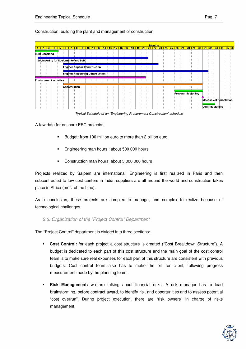
Construction: building the plant and management of construction.
Typical Schedule of an “Engineering Procurement Construction” schedule
A few data for onshore EPC projects:
� Budget: from 100 million euro to more than 2 billion euro
� Engineering man hours : about 500 000 hours
� Construction man hours: about 3 000 000 hours
Projects realized by Saipem are international. Engineering is first realized in Paris and then
subcontracted to low cost centers in India, suppliers are all around the world and construction takes
place in Africa (most of the time).
As a conclusion, these projects are complex to manage, and complex to realize because of
technological challenges.
2.3. Organization of the “Project Control” Department
The “Project Control” department is divided into three sections:
� Cost Control: for each project a cost structure is created (“Cost Breakdown Structure”). A
budget is dedicated to each part of this cost structure and the main goal of the cost control
team is to make sure real expenses for each part of this structure are consistent with previous
budgets. Cost control team also has to make the bill for client, following progress
measurement made by the planning team.
� Risk Management: we are talking about financial risks. A risk manager has to lead
brainstorming, before contract award, to identify risk and opportunities and to assess potential
“cost overrun”. During project execution, there are “risk owners” in charge of risks
management.
Engineering Typical Schedule Pag. 8
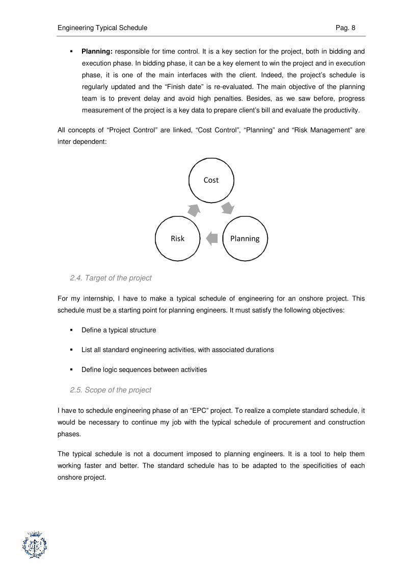
� Planning: responsible for time control. It is a key section for the project, both in bidding and
execution phase. In bidding phase, it can be a key element to win the project and in execution
phase, it is one of the main interfaces with the client. Indeed, the project’s schedule is
regularly updated and the “Finish date” is re-evaluated. The main objective of the planning
team is to prevent delay and avoid high penalties. Besides, as we saw before, progress
measurement of the project is a key data to prepare client’s bill and evaluate the productivity.
All concepts of “Project Control” are linked, “Cost Control”, “Planning” and “Risk Management” are
inter dependent:
Cost
PlanningRisk
2.4. Target of the project
For my internship, I have to make a typical schedule of engineering for an onshore project. This
schedule must be a starting point for planning engineers. It must satisfy the following objectives:
� Define a typical structure
� List all standard engineering activities, with associated durations
� Define logic sequences between activities
2.5. Scope of the project
I have to schedule engineering phase of an “EPC” project. To realize a complete standard schedule, it
would be necessary to continue my job with the typical schedule of procurement and construction
phases.
The typical schedule is not a document imposed to planning engineers. It is a tool to help them
working faster and better. The standard schedule has to be adapted to the specificities of each
onshore project.
Engineering Typical Schedule Pag. 9
3. Description of existing work
3.1. EMC : Engineering Management Class
This document is a standard corporate document. The purpose of the EMC is to list, to define, to
standardize and to describe all engineering activities relevant to onshore plants. The standard
schedule must be based on the EMC.
The EMC covers the whole cycle of a project, excluding construction, from basic to detailed
engineering to delivery of materials at site. It is a reference tool for engineering processes and a
starting point to set the planning and the control of projects for onshore plants.
Onshore EMC had been first issued in 1986 and since this date, it had been regularly updated in order
to consolidate the experience acquired with projects execution and to create an exhaustive database
for engineering activities.
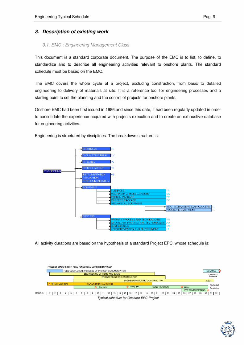
Engineering is structured by disciplines. The breakdown structure is:
All activity durations are based on the hypothesis of a standard Project EPC, whose schedule is:
Typical schedule for Onshore EPC Project

Engineering Typical Schedule Pag. 10
Status for main deliverables are based on the following rules and process :
Typical process for deliverable status
In each discipline, activities are grouped and sorted by “EMC Index Form”. There is a total of more
than three hundreds EMC Index Forms for all engineering activities. Here is an example of an EMC
Index Form, with the detail of main information we can find on it:
Title of EMC
Brief description of
activities
Schedule of the
standard project
Activity code

Engineering Typical Schedule Pag. 11
EMC Index Forms are issued by SAIPEM Milano, the head office. Consequently, there are based on
SAIPEM Milano organization, which is a bit different from the SAIPEM SA organization, based in
Paris. To realize the typical schedule, it is required to adapt this structure.
Inputs of the activity
Outputs of the activity
Deliverable
s
Comments

Engineering Typical Schedule Pag. 12
Breakdown Structure of engineering in SAIPEM SA (Paris)
3.2. “Handbook for planning engineers, v0”
This handbook was written by a trainee and is aimed at junior planning engineers. It is the result of
interviews with all discipline leaders (Process, Piping, Electrical…), and it deals with main engineering
activities realized by each discipline. This is a description of all typical engineering activities performed
and all typical documents issued during the engineering of an onshore plant.
Example of the content of this handbook, for “Piping” dedicated part:
Index for “Piping” dedicated part

Engineering Typical Schedule Pag. 13
Extract of content for “Piping” dedicated part
The last part of this handbook is dedicated to the most important flows between engineering
disciplines.
There is no link between this document and “Engineering Management Class” (EMC). It is a
description of how engineering works in SAIPEM SA, of the main documents issued and of the main
relationships between disciplines. For example, the structure of the handbook is different from the
structure of EMC, and activity names in the handbook do not always match with those in the EMC
Index Forms.
To sum up:
Engineering Typical Schedule Pag. 14
4. Project Requirements
4.1. Tool : Primavera P6
Primavera P6 is the software used by SAIPEM SA to schedule its projects. This software is one of the
highest standards used in scheduling major projects (software used by Areva, Total, Technip,
Hyundaï, Samsung, SNCF…). It is a powerful and complex tool used to schedule activities (several
thousand activities for projects realized by SAIPEM), resources, and to control project’s progress.
Primavera P6 operates like a data base, several people can work on the same project at the same
time. The main operating rules of P6 are:
� First: create an activity, identified by an “Activity ID” and an “Activity Name”
� Second: assign data to this activity (calendar, duration, relationships, resources, activity
codes…)
� Third: define a layout, using filters and organization breakdown. This third point is very
important. Thanks to this function, we can optimize organization of the schedule depending
on the specifics needs, we can show only what we need.
Snapshot of Primavera P6
The most important property of Primavera P6 is it “Multi Project” organization. All projects can be
sorted in the same data base, what enable to share scheduling methods and to manage easily and
efficiently the return of experience.

Engineering Typical Schedule Pag. 15
4.2 Schedule structure
First of all, it is important to remind that a planning is a communication tool. This document is a
management tool and it is used by all the key people of the project.In spite of the quantity of
information we can find through it, a planning must highlight the critical tasks and make easier the
control of the project.
The structure of the planning is defined in Primavera P6 with “Activity Codes” and the WBS. These
activity codes are similar to tags put on the different activities. An activity code can refer to a kind of
activity, to a physical unit of the plant, to a work package, to a phase of the project, to an EMC…We
can then create filters and organization thanks to the activity codes and then define layout thanks to
filters.
The “Multi Project” conception of Primavera P6 makes possible the use of this standard structure for
all projects.
Activity Codes defined for the standard schedule are:
� Department: to group and sort activities by engineering departments, following structure of
engineering in SAIPEM SA
� Unit: for projects with several physical units, to can create a layout for each unit of the plant
� Status: to filter on the status of deliverables. Can be especially interesting to see all scheduled
dates of deliverable “Issue For Construction”, and the effect of a delay for the construction

Engineering Typical Schedule Pag. 16
� EMC Codes: to link all activities with their relevant EMC Data Sheet
� Phase: to create a layout for each phase of the project (filter).
4.3 Codification for activities
As the structure of a planning is important to emphasize the relevant information, the codification for
activities is very important to quickly identify the activity we are talking about. For example, projects
are often divided into several units, and the same activity can be repeated on each unit. In such case,
the “Activity Name” is not sufficient to differentiate the activities. The activity ID must be unique in the
project.
The rules we have to follow for coding activities are:
� Unit: for several units projects
� Phase: Engineering (E), Procurement (P) or Hammock (H)
� EMC: to link with EMC Index Form
� Status: to quickly identify the status of a deliverable ( W = Issue for Approval, X = Issue for
Design, Y = Issue for Construction, Z = As Built)
� Activity Sequential Number: to differentiate activities in a same group
Engineering Typical Schedule Pag. 17
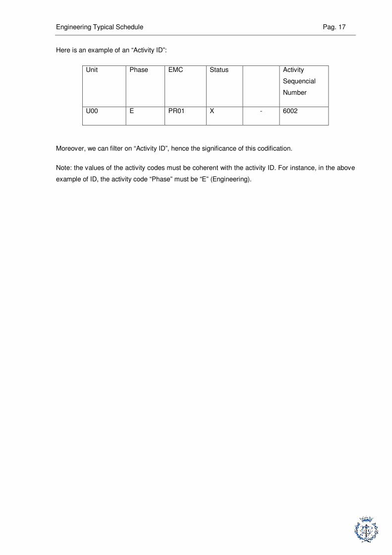
Here is an example of an “Activity ID”:
Unit Phase EMC Status Activity
Sequencial
Number
U00 E PR01 X - 6002
Moreover, we can filter on “Activity ID”, hence the significance of this codification.
Note: the values of the activity codes must be coherent with the activity ID. For instance, in the above
example of ID, the activity code “Phase” must be “E” (Engineering).

Engineering Typical Schedule Pag. 18
5. Knowledge prerequisites
5.1. Theoretical concepts for planning
5.1.1. Float and critical path
The two previous points are very important concepts when scheduling activities. The main goal at the
time of scheduling projects is reduce and minimize the time necessary to achieve the project. Then, in
the execution phase, the main objective of project control team is to ensure that project will respect
scheduled “lead time” and approved budget.
Float: it is the maximal quantity of time an activity can be delayed without postponing the end of the
project. A float can be applied to a single activity or to the entire project.
Total Float: it is the maximal quantity of time an activity can be delayed without changing the “Late
Finish” of the project.
Total Float = “Late Finish” – “Early Finish”
Free Float: it is the maximal quantity of time an activity can be delayed without postponing any other
activity. There is always Free Float ≤ Total Float.
Critical path: it is the sequence of activities with null floats, from the beginning of the project to the
end of the project. Any delay on the critical path will postpone the end of the project.
Critical activity: it is an activity located on the critical path, that is to say an activity with a null float.
5.1.2. Different kinds of links
A planning is a logic network where all activities are linked. There are four kinds of links: “finish to
finish”, “finish to start”, “start to finish”, “start to start”.
Finish to finish: means that successor can end only if predecessor is finished.
Activity A
Activity B
For example, if “Activity A” is “Frame erection” and “Activity B” is “Frame painting”, we understand that
we cannot finish “Frame painting” if “Frame erection” is still being erected.
Finish to start: it is the most frequently used link. Means that successor cannot start before
predecessor is achieved.
Engineering Typical Schedule Pag. 19
Activity A
Activity B
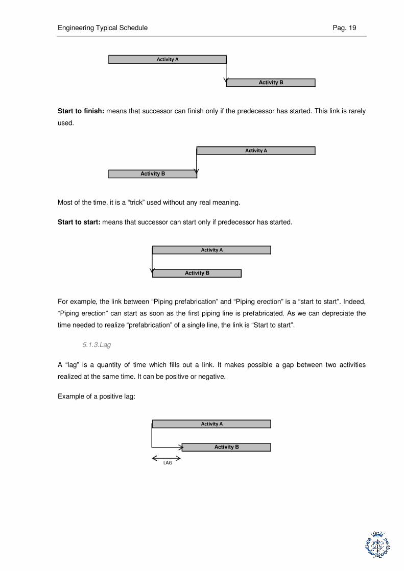
Start to finish: means that successor can finish only if the predecessor has started. This link is rarely
used.
Activity B
Activity A
Most of the time, it is a “trick” used without any real meaning.
Start to start: means that successor can start only if predecessor has started.
Activity B
Activity A
For example, the link between “Piping prefabrication” and “Piping erection” is a “start to start”. Indeed,
“Piping erection” can start as soon as the first piping line is prefabricated. As we can depreciate the
time needed to realize “prefabrication” of a single line, the link is “Start to start”.
5.1.3. Lag
A “lag” is a quantity of time which fills out a link. It makes possible a gap between two activities
realized at the same time. It can be positive or negative.
Example of a positive lag:
LAG
Activity A
Activity B

Engineering Typical Schedule Pag. 20
Example of a negative lag:
LAG
Activity A
Activity B
5.1.4. An example: typical sequence
Here is an example of a typical sequence from the department “Equipment”.
1 2 3 4 5 6 7 8 9 10 11 12 13 14
Technical Specification
Material Requisition/Inquiry
Technical Evaluation
Purchase Order
LAG Vendor doc. Follow up
Technical Specification: it is a document which defines main criteria of study, of building equipment
and technical requirements from engineering departments.
Material Requisition: it is a document made to produce a “Purchase Request”. The content of this
document is: scope, applicable documents (technical documents for furnisher to make the equipment)
and list of documents the vendor has to supply.
Technical evaluation: technical evaluation of different bids from vendors.
Vendor doc: documents that vendor has to supply to the company, to ensure equipment complies with
requirements.
All the links between the different activities are links “Finish to Start”, expected between “Material
Requisition” and “Technical Evaluation”. Indeed, the lag is the time necessary for the vendors to study
the “Purchase Request” and to prepare their bid.
5.2. Specific culture in Oil and Gas industry
5.2.1. Main engineering activities
Of course, to schedule engineering phase for an onshore project, it is necessary to have specific
culture in oil and gas industry. This is why the first part of my internship was dedicated to studying
main engineering activities. It is required to understand main engineering activities, main links
between these activities and main relationships between the different engineering phases.

Engineering Typical Schedule Pag. 21
5.2.2. An example: Piping
“Piping” department is responsible for the arrangement of plant, location of units,
equipment…Besides, this department is responsible for the design of piping (above ground and
underground) and main structures to support pipes and cables.
5.2.2.1. “Plot Plan” and “Single Line Diagram”
As we said before, geographical organization of the plant is under “Piping” responsibility. This goal is
reached with emission of layouts called “Plot Plan”. An “Overall Plot Plan” is a general map of the
plant, whereas a “Unit Plot Plan” is a map of a single unit.
First, there is the “Preliminary Routing”. This is a 2D layout of main piping routings.
Example of an “Overall Plot Plan”
Example of a “Unit Plot Plan”

Engineering Typical Schedule Pag. 22
“Piping” department is also responsible for the design of “Pipe Rack Single Line Diagram”. “Pipe Rack”
is a structure (steel or concrete) designed to support piping and cables. “Piping” engineers design
shape of the racks and they estimate the loads of the racks.
Example of a “Rack single line diagram”
5.2.2.2. “Preliminary Routing” and “3D Model”
One of the most important activities for engineering is setting and design of the “3D Model”. This is a
computerized model of the plant, which shows all units, piping and equipment arrangement.
The functions of the “3D Model” are: make easier clash management (between piping, piperacks…)
and coordination between engineering departments, and for the client, it can be a training tool for
operators and a tool for maintenance.
Example of a “3D Model”
5.2.2.3. Underground Networks
Underground and above ground networks are differentiated, but both under “Piping” responsibility. The
gravitational networks (for sewer water), pressured water for fire protection and electrical networks are
underground networks.
Engineering Typical Schedule Pag. 23
5.2.2.4. “Isometrics” and “Material Take Off”
An “Isometric” is a 3D drawing of a piping line. This document is quoted but is not a scale drawing. It is
extracted from the “3D Model” and it is the document used on a yard to start “Piping prefabrication”.
Example of “Isometric”
For EPC (Engineering Procurement Construction) Projects, the company has to buy material
necessary for construction, and in this case, company has to buy piping. As “Piping” just need bulk
material, MTO (Material Take Off) for piping are necessary.
MTO are bill of quantities required by the project, and basically, purchasing process is made of three
stages, for a total of 15 months.
The first MTO issue is based on “PID (Issue for Approval)” and “Preliminary Routing”, the second MTO
is an update of the first one while MTO3 is based on isometrics.
Each MTO issue is aimed to precise the whole quantity of piping material required.
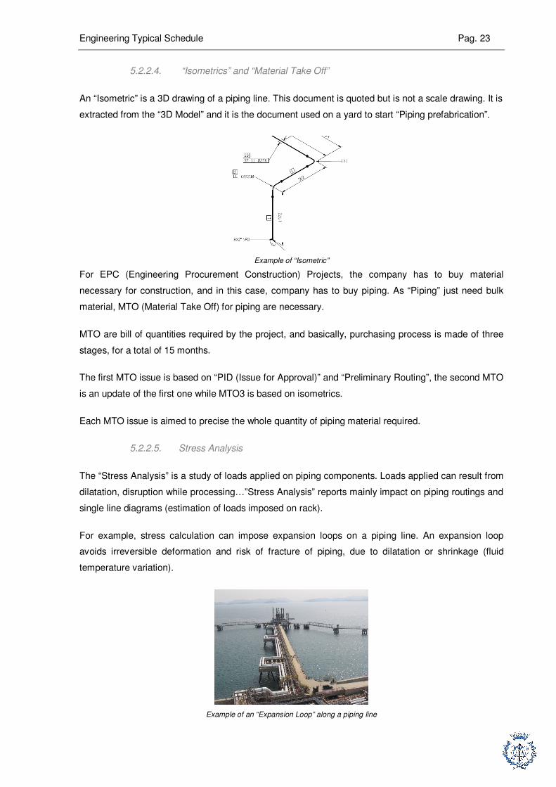
5.2.2.5. Stress Analysis
The “Stress Analysis” is a study of loads applied on piping components. Loads applied can result from
dilatation, disruption while processing…”Stress Analysis” reports mainly impact on piping routings and
single line diagrams (estimation of loads imposed on rack).
For example, stress calculation can impose expansion loops on a piping line. An expansion loop
avoids irreversible deformation and risk of fracture of piping, due to dilatation or shrinkage (fluid
temperature variation).
Example of an “Expansion Loop” along a piping line

Engineering Typical Schedule Pag. 24
5.3. Conclusion
We have just seen main engineering activities for “Piping” department. The prerequisites skills for
making a level 3 engineering schedule are project management theoretical concepts and a strong
technical culture for oil and gas industry.

Engineering Typical Schedule Pag. 25
6. Methodology for planning realization
6.1. Global methodology
We had to schedule eight engineering departments, which means several hundreds of activities.
At the time of scheduling engineering phase, we had to take into account relationships “intra
department” and relationships “inter department”. The method we chose for this exercise had to make
possible:
� All trainees from the team can work simultaneously with independence
� Make easier progress control
� Enable approval process
We decided to schedule engineering departments one by one, to first link only “intra department
relationships” and finally, to link “inter department relationships”.
To begin, we realized “Gantt Diagrams”, on paper supports and then, we implemented it into the
software “Primavera P6”. We did “Gantt Diagrams” together and after, we split the schedule into
trainee’s team by engineering department.
« Gantt Diagrams » on paper support
6.2. Adapting EMC Structure to SAIPEM SA Structure
6.2.1. Engineering department
We remind that “Engineering Management Class” was first issued by SAIPEM Milano, the head office
of SAIPEM with a different structure from SAIPEM SA (in Paris). The typical schedule is aimed to
SAIPEM SA and will be used by planning engineers from SAIPEM SA, so we had to adapt it to
engineering organization in Paris.

Engineering Typical Schedule Pag. 26
The differences between the two organizations are:
� There is no “Pipelines” department in Paris, because it is a specific kind of onshore projects.
� In SAIPEM Milano structure, “Process” department is split into primary and secondary process
technologies. There is no distinction between primary and secondary technologies in Paris.
� There is a “Material Management” department in Paris, whereas there are no similar
departments in Milano.
� “Loss Prevention Engineering” is a part of “Process” department in Milano, whereas it is an
independent department in Paris.
� “Material” is an independent department in Paris, whereas it is split on other departments in
Milano (on Electrical, Piping, Loss Prevention Engineering and Equipment)
These differences of structure between our reference document and the schedule we had to realize
were previously solved defining the “Activity Code” “DEPARTMENTS_FOR_EMC”. The best example
is for “Material” department:
Example of “Activity Code” hierarchy for Material department
We can see with this solution the synthesis between Paris and Milano structure. The schedule is
structured following SAIPEM SA organization but we can read in the “Activity Code” the relevant
department for the activity in Milano and the relevant EMC Data Sheet for the activity.
6.2.2. Group of activities
To try to lighten the schedule, I decided to group activities and create typical sequences. I did it for the
department “Equipment” and for the purchasing activities in the department “Electrical”.
The department “Equipment” is divided into five kinds of equipment:
� Furnaces
� Machinery and engines for chemical and petrochemical plant
� Heat exchangers and Air Coolers
� Pressure Equipment, Columns, Reactors
� Energy Packages
� Process package and handling
Engineering Typical Schedule Pag. 27
Each “section” dedicated to a kind of equipment is divided into various index forms, one index form for
one specific equipment. For example, there are about ten data sheets for “Furnaces”, more than ten
for “Pressure Equipment, Columns, Reactors”…As activities, duration and predecessors/successors
are similar into a “section”, I decided to create a typical sequence of activity for each section.
I did the same for the department “Electrical”. All activities concerning purchasing in this department
can be grouped in “Itemized Equipment” and “Bulk Material”. Into the group “Itemized Equipment”, I
had to create sub groups, split based on when these activities are scheduled (whereas in the
department “Equipment”, equipments grouped together are similar equipment).
For example, the first group for electrical equipment is dedicated to “Long Lead Items” (a “Long Lead
Item” is an equipment with a very long lead time).
6.2.3. Status of documents
These modifications are minors. Most of important deliverables are issued in three steps. The
codification for these three steps in “EMC Data Sheets” is:
� First step: IFC = Issue For Comment
� Second Step: IFD = Issue For Design
� Third Step: FC = For Construction
This codification of deliverable status was adapted to SAIPEM SA codification:
� “IFC = Issue For Comment” replaced by “IFA = Issue for Approval”
� “IFD = Issue For Design” is not changed
� “FC = Issue For Construction” replaced by “IFC = Issue For Construction”
6.3. Linking activities
6.3.1. Approach
This is our earned value. The schedule we made is a typical document. As a consequence, durations
of activities will be adapted to specifications of each project; activities can be duplicated depending on
specific needs of the project, sequences for equipment will be distinct for each equipment…But if we
want to convert this document into a real efficient tool which will be useful for planning engineers, we
have to pay a special attention to the logic sequence of engineering.
The easiest way to link activities and to make a standard document is: create a “Start Milestone” for
the contract award, link all activities to this milestone with a link “Finish to Start + lag”, with a quantity
of time for the lag given by “EMC Index Form”.

Engineering Typical Schedule Pag. 28
Such a planning would be useless for the company. During execution phase, it makes any update
impossible. As a consequence, it would just be a debased revision of “Engineering Management
Class”, approved by the head office of SAIPEM.
To create a typical sequence of activities with logic links, it is required to:
� Understand activities, what are they about.
� Identify inputs/outputs of each activity.
� Identify kind of links to use, keeping in mind that the schedule will be updated, so taking into
account the way an activity will impact another one.
6.3.2. An example : scheduling a typical sequence for engineering
6.3.2.1. Intra department Relationship
Intra department links for EMC TB03:

Engineering Typical Schedule Pag. 29
“General layout of plant and major components”: first emission of plot plan.
Predecessors: information from FEED.
Link: “Finish to Start” with “Start Project Milestone”
“Completion with all components information”: second emission of plot plan.
Predecessors: data from other department.
Link: at inter department relationship step.
“Update with vendor drawing”: update of plot plan, with equipment drawing from vendors
Predecessors: previous activity. The “Issue For Design” version is completed during this
activity.
Link: “Finish to Start” with the “Issue For Design” emission.
“Update with data of engineering”: the “plot plan” is the plan of plant and unit. During this phase,
modifications on the plot plan, due to studies from other department are implemented on the plot plan.
At this step of the project, changes on the plot plan are minors.
Predecessors: data from other department.
Link: at inter department relationship step.
“Update as built”: plot plan updated with data from construction.
Predecessors: data from construction.
Link: no link at this step.
“Single Line Structure”: definition of shape for “piperacks”, first emission.
Predecessors: data from FEED and from other departments.
Link: “Finish to Start” with “Start Project Milestone”.
“Completion with all information”: shapes of “piperacks” are finalized. Assessment of loads imposed to
the “piperacks”. Status “IFD”.
Predecessors: data from other department.
Link: at inter department relationship step.
Engineering Typical Schedule Pag. 30
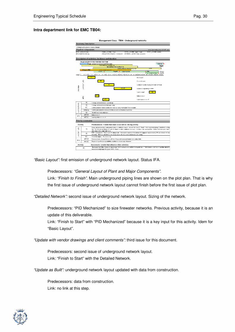
Intra department link for EMC TB04:
“Basic Layout”: first emission of underground network layout. Status IFA.
Predecessors: “General Layout of Plant and Major Components”.
Link: “Finish to Finish”. Main underground piping lines are shown on the plot plan. That is why
the first issue of underground network layout cannot finish before the first issue of plot plan.
“Detailed Network”: second issue of underground network layout. Sizing of the network.
Predecessors: “PID Mechanized” to size firewater networks. Previous activity, because it is an
update of this deliverable.
Link: “Finish to Start” with “PID Mechanized” because it is a key input for this activity. Idem for
“Basic Layout”.
“Update with vendor drawings and client comments”: third issue for this document.
Predecessors: second issue of underground network layout.
Link: “Finish to Start” with the Detailed Network.
“Update as Built”: underground network layout updated with data from construction.
Predecessors: data from construction.
Link: no link at this step.
Engineering Typical Schedule Pag. 31
“MTO 1”: first material take off. Bill of quantities.
Predecessors: “Plot Plan”, “Specification of Piping Component”. The first MTO is a first
appraisal of quantities. As we saw before, main piping lines are shown on the plot plan, which
is a scale plan. “Specification of Piping Component” provides type of material required for
piping.
Link: “Start to Start” with the second issue of plot plan. Information provided at this step is
enough for a first appraisal. “Finish to Start” with “Specification of Piping Component”. These
are key data to purchase material.
“MTO 2”: second material take off. Update of previous activity.
Predecessors: second issue of “Plot Plan”. Same reason as mentioned above.”MTO 1”.
Link: “Finish to Start” with “MTO 1”. “Finish to Finish” with the second issue of plot plan.
Modification and complement on the plot plan are taken into account for this second MTO.
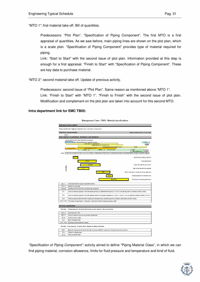
Intra department link for EMC TB05:
“Specification of Piping Component”: activity aimed to define “Piping Material Class”, in which we can
find piping material, corrosion allowance, limits for fluid pressure and temperature and kind of fluid.
Engineering Typical Schedule Pag. 32
Predecessors: data from “Process” and “Material” departments.
Link: at inter department relationship step.
“Valve Specification”: definition of valves type.
Predecessors: data from “Process”. “Specification of Piping Component”, because valves are
set on piping, their specification depends on piping specification.
Link: “Finish to Start” with “Specification of Piping Component” because it is a key data for this
activity. Data from process at inter department relationship step.
“Update with engineering and client”: update of “Specification of Piping Component” and “Valve
Specification” following requirements from client and other engineering departments.
Predecessors: comments from engineering departments and client, “Specification of Piping
Component” and “Valve Specification”.
Link: “Finish to Start + lag” with “Valve Specification”.
“Bids: control and technical appraisal”: technical evaluation of bids from vendors for piping
components.
Predecessors: technical bids from vendors after “MTO 1 for piping components”.
Link: “Finish to Start + lag” with “Piping Bulk First MTO”.
“Bids for material not covered in previous agreement”: technical evaluation of bids from vendors for
piping components.
Predecessors: technical bids from vendors after MTO 2 for piping components.
Link: “Finish to Start + lag” with “MTO 2 for piping components”.
“Technical appraisal for Motorized valves”: technical evaluation for “Piping” scope of motorized valves.
Purchasing process for these valves makes part of “Instrumentation” scope.
Predecessors: data from “Instrumentation”.
Link: at inter department relationship step.
“Final Revision of Material Specification”: check and comments of drawings issued by vendors.
Predecessors: comments and drawings issued by vendors.
Link: “Finish to Start” with “Technical Evaluation” in the EMC Data Sheet TB06B, because this
activity ends with the first “Purchase Order” for “Piping Components”, and consequently, the
first issue of drawings by vendors.
Engineering Typical Schedule Pag. 33
6.3.2.2. Inter department Relationship
Inter department links for EMC TB03:
“General layout of plant and major components”:
Predecessors: “Equipment List” and “PFD/UFD” from “Process” department.
Link: “Finish to Finish” with second issue of “Equipment List”. This list is not a key document to
draw the first issue of plot plan, so “General layout of plant and major components” can start
without this document. However, all major equipments must be on the first emission of plot
plan; this is why there is this link. “Finish to Finish” with “PFD/UFD IFD”. “PFD/UFD” provides
main connections between equipment and consequently, main piping lines.
“Completion with all components information”:
Predecessors: “PID/UID IFD” from “Process” department, and “Investigation Report” from
“Civil” department.
Link: “Finish to Finish” with “PID/UID IFD”. “Finish to Finish” with “Investigation Report”.
“Investigation Report” is the result of “Site Investigation” made by “Civil” department because
this report includes topographic studies. Topographic data are available in the FEED. There
are inputs for first issue of plot plan, and then, “Investigation Report” updates these data. That
is why the link is “Finish to Finish”.
“Update with vendor drawings”: no inter department relationships.
“Update with data of engineering”: no inter department relationships.
“Update As Built”: idem.
“Single Line Structure”:
Predecessors: first issue if “PFD/UFD”, first issue of “Equipment List”.
Links: “Finish to Finish” for both activities. Same logic as the one used for “General layout of
plant and major components”.
“Completion with all information”:
Predecessors: “Investigation Report”, “PID/UID IFD” and “Fire Proofing Layout” from “Loss
Prevention Engineering” department.
Link: “Finish to Finish” for “Investigation Report” and “PID/UID IFD” for the same reasons as
mentioned above for “Completion with all components information”. “Fire proofing layout”
mentioned structures which have to be protected against fire. “Fire proofing” is a superficial
treatment applied on steel structure. This kind of protection is previous in the “Passive Fire
Protection” strategy.
Engineering Typical Schedule Pag. 34
Inter department links for EMC TB04:
“Basic Layout”: no inter department relationships.
“Detailed Network”:
Predecessors: “Sewer scheme plan” from “Civil” department.
Links: “Finish to Finish”. Sewer networks are underground networks, under “Civil”
responsibility. They are implemented into “Underground network layout” by “Piping”
department.
“Update with vendor drawings and client comments”:
Predecessors: “Main Foundation Layout” from “Civil” department.
Links: “Finish to Finish”. “Main foundation Layout” is an input data for “Underground Network
Layout” because it is a tool to manage clash between underground piping lines and
foundations.
“Update with engineering activities”: no inter department relationships.
“Update as built”: no inter department relationships.
“MTO 1”: no inter department relationships.
“MTO 2”: no inter department relationships.
Inter department links for EMC TB05:
“Specifications of piping components”:
Predecessors: first issue of “PID/UID” from “Process” department, “Material Selection
Diagram” from “Material” department.
Links: “Finish to Start” with “Material Selection Diagram” because it is a key input to realize
“Piping Material Class”, which is the deliverable issued by this activity. “Start to Start” with
“PID/UID IFD” because “PID/UID IFD” feeds “Piping Material Class” with data relevant to
properties of processed fluid.
“Valve specifications”:
Predecesors: idem.
Links: idem.
“Update with engineering and client”: no inter department relationships.
“Bids: control and technical appraisal (for piping components)”: no inter department relationships.
Engineering Typical Schedule Pag. 35
“Bids for materials not covered in previous agreement”: no inter department relationships.
“Technical appraisal for motorized valves”:
Predecessors: “Technical Evaluation” for control, motorized and safety valves, from
“Instrumentation” department.
Link: “Finish to Start” with “Technical Evaluation” from “Instrumentation”. “Piping” is involved in
purchasing process for “Motorized valves” because of the interaction between valves and
piping lines.
“Final revision of material specifications”: no inter department relationships.
6.3.3. Conclusion
We have just seen an example what we did for all engineering activities.
6.4. Implementation into Primavera P6
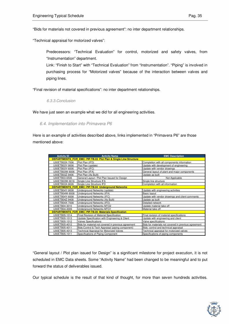
Here is an example of activities described above, links implemented in “Primavera P6” are those
mentioned above:
Activity ID Activity Name EMC Description
U00ETB03X-7006 Plot Plan (IFD) Completion with all components information
U00ETB03Y-9006 Plot Plan (update) Update with development of engineering
U00ETB03Y-6006 Plot Plan (IFC) Update with vendor drawings
U00ETB03W-8006 Plot Plan (IFA) General layout of plant and major components
U00ETB03Z-9406 Plot Plan (As Built) Update as built
U00ETB03-6506 General Layout / Plot Plan Issued for Design Not Applicable
U00ETB03W-9016 Single Line Structure IFA Single line structure
U00ETB03X-9026 Single Line Structure IFD Completion with all information
U00ETB04Y-9008 Underground Networks (update) Update with engineering activities
U00ETB04W-8008 Underground Networks (IFA) Basic layout
U00ETB04Y-6008 Underground Networks (IFC) Update with vendor drawings and client comments
U00ETB04Z-9408 Underground Networks (As Built) Update as built
U00ETB04X-7008 Underground Networks (IFD) Detailed network
U00ETB04-3010 Underground Networks MTO2 Update material take off
U00ETB04-3009 Underground Networks MTO1 Material take off
U00ETB05-1014 Final Revision of Material Specification Final revision of material specifications
U00ETB05-1013 Update Specification with Engineering & Client Update with engineering and client
U00ETB05-1012 Valves Specifications Valve specifications
U00ETB05-4012 Bids for material not covered in previous agreement Bids for materials not covered in previous agreement
U00ETB05-4011 Bids:Control & Tech Appraisal (piping component) Bids: control and technical appraisal
U00ETB05-4013 Technical Appraisal for Motorized Valves Technical appraisal for motorized valves
U00ETB05-1011 Specifications of Piping Component Specifications of piping components
DEPARTMENTS_FOR_EMC: PIP.TB.03 Plot Plan & Single Line Structure
DEPARTMENTS_FOR_EMC: PIP.TB.04 Underground Networks
DEPARTMENTS_FOR_EMC: PIP.TB.05 Materials Specification
“General layout / Plot plan issued for Design” is a significant milestone for project execution, it is not
scheduled in EMC Data sheets. Some “Activity Name” had been changed to be meaningful and to put
forward the status of deliverables issued.
Our typical schedule is the result of that kind of thought, for more than seven hundreds activities.

Engineering Typical Schedule Pag. 36
Here is the schedule of all activities described above, after implementation into “Primavera P6”.

Engineering Typical Schedule Pag. 37
7. Approval process
7.1. Mutual check into the trainees team
As explained before, we worked together to link activities on “Gantt Diagrams” (paper support), we just
split it to implement into the software “Primavera P6”. So each member of the team had to implement
his part into the software, and then, each member had to check the work of other members of the
team.
This first step of checking process is basic, we just checked if all “Gantt Diagrams” are correctly
implemented in the software.
7.2. Critical Path Analysis
This is the second step of confirmation of the job we made. In this step we had to analyze the
sequence of activities on the critical path.
The goal with this analysis is to ensure that all activities on the critical path are significant activities
with a real impact on project’s progress. Thus, we make sure the typical schedule proposed is adapted
to progress control and consistent with the execution of a project.
After a few corrections, we finally got the critical path shown above. Even if critical path is mostly
significant for EPC Projects (Engineering Procurement Construction), in our case, it is a good way to
assess consistency of our schedule. We can see that engineering duration depends on “Piping”
activities: “Plot Plan”, 3Underground Network”, “3D Model” and “Isometrics”. These activities are both
important for engineering and construction, there are really significant for the physical progress of the
project. Thus, we can conclude that main engineering activities logics are respected in our schedule.

Engineering Typical Schedule Pag. 38
7.3. Approval by engineering discipline leaders
This is the final stage of typical schedule approval process.
Engineering discipline leaders are people with the best skills to check typical logic sequence of their
disciplines. Besides, as we planned their job, they have to approve it.
Moreover, the schedule we made is a standard document, it is a new tool. Approval by engineering
discipline leaders should make easier it passing among planning engineers from the project control
department. It is a new step to convert this standard document into an efficient tool.
To conclude, this final step of process approval is the most important for our job. There are two goals:
make sure this schedule is right, give it credibility and convert this document into a useful tool for the
“Project Control” department of SAIPEM SA.
Engineering Typical Schedule Pag. 39
8. User guide: “Handbook for planning engineers, v1”
8.1. Purpose of this document
This document is an update of an existing document “Handbook for planning engineers, v0”. It is
aimed at junior engineers, from project control department or from any other department. It is a
training tool for everyone who needs to develop his technical culture for oil and gas industry. We can
find in this document:
� Explanation of main engineering activities for each department
� Explanation of relationships intra and inter departments
� Special emphasis on main engineering logics
The “Handbook for planning engineers” is an intermediary document between a junior planning
engineer and the engineering typical schedule.
8.2. Changes from “Handbook for planning engineers, v0”
For this second issue of the handbook, the technical content had been enriched with more
explanations, extracts from typical documents when they are mentioned and matrix to summarize
logics between main documents issued by engineering department.
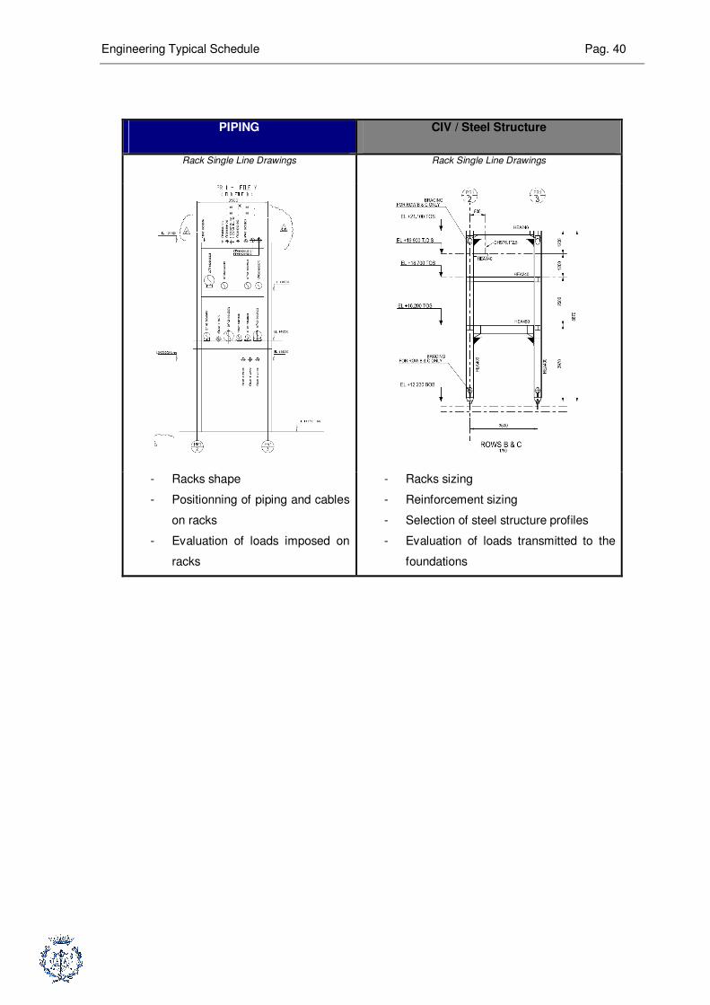
Besides, I put a special emphasize on exchanges between engineering departments for a same
document. Here is an example, for the realization of “Single line structures for piperack”:
Engineering Typical Schedule Pag. 40
PIPING CIV / Steel Structure
Rack Single Line Drawings Rack Single Line Drawings
- Racks shape
- Positionning of piping and cables
on racks
- Evaluation of loads imposed on
racks
- Racks sizing
- Reinforcement sizing
- Selection of steel structure profiles
- Evaluation of loads transmitted to the
foundations
Engineering Typical Schedule Pag. 41
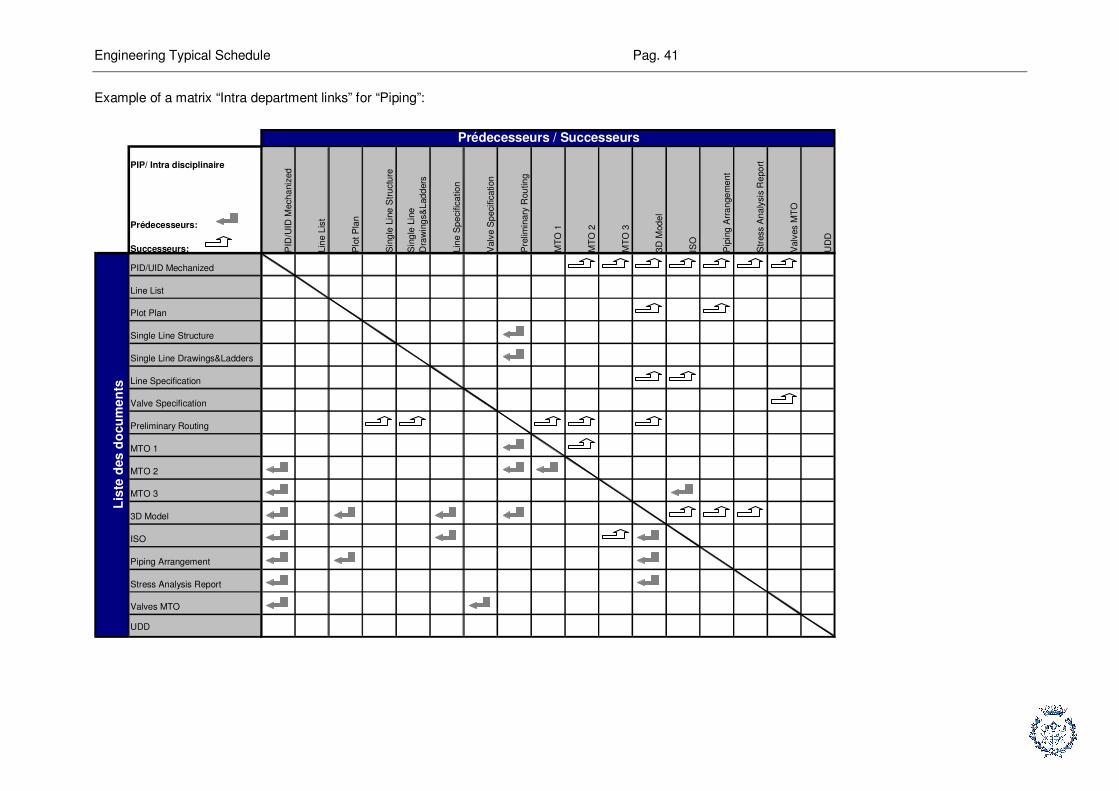
Example of a matrix “Intra department links” for “Piping”:
PIP/ Intra disciplinaire
Prédecesseurs:
Successeurs: PID
/UID
Mech
aniz
ed
Lin
e L
ist
Plo
t P
lan
Sin
gle
Lin
e S
tru
ctu
re
Sin
gle
Lin
e
Dra
win
gs&
Lad
ders
Lin
e S
pe
cific
atio
n
Va
lve S
pecific
ation
Pre
limin
ary
Rou
tin
g
MT
O 1
MT
O 2
MT
O 3
3D
Mod
el
ISO
Pip
ing
Arr
an
ge
me
nt
Str
ess A
na
lysis
Re
po
rt
Va
lves M
TO
UD
D
PID/UID Mechanized
Line List
Plot Plan
Single Line Structure
Single Line Drawings&Ladders
Line Specification
Valve Specification
Preliminary Routing
MTO 1
MTO 2
MTO 3
3D Model
ISO
Piping Arrangement
Stress Analysis Report
Valves MTO
UDD
Lis
te d
es
do
cu
me
nts
Prédecesseurs / Successeurs
Engineering Typical Schedule Pag. 42
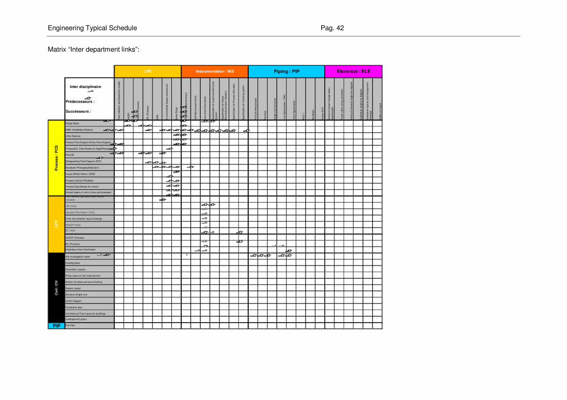
Matrix “Inter department links”:
Inter disciplinaire
Prédecesseurs :
Succésseurs :
Fla
re r
adia
tion a
nd d
ispers
ion s
tudie
s
HA
ZID
HA
ZO
P (
Pro
cess)
SIL
(P
rocess)
QR
A
Environm
enta
l Im
pact A
ssessm
ent
Nois
e S
tudy
PID
Mechaniz
ed (
pro
cess)
UID
Mechaniz
ed (
F&
G)
Instr
um
ent D
ata
Sheet
Specific
ation for
Superv
isio
n&
Contr
ol
Syste
m
Specific
ation for
Safe
ty,
Ala
rm&
Auto
mation S
yste
ms
Specific
ation for
Pro
cess S
imula
tor
Specific
ation for
mete
ring s
yste
m
PID
/UID
Mechaniz
ed
Plo
t P
lan
Sin
gle
Lin
e S
tructu
re
Lin
e S
pecific
ation /
PM
C
Valv
e S
pecific
ation
MT
O 1
3D
Model
Valv
es M
TO
Ele
ctr
ical S
yste
m D
esig
n B
asis
Specific
ation
Pow
er
cable
siz
ing c
alc
ula
tion
Ele
ctr
ical G
enera
l sin
gle
lin
e d
iagra
m
Substa
tion s
ingle
lin
e d
iagra
m
Substa
tion layouts
and a
rrangem
ent
dra
win
gs
Cable
run layout
Design Basis
HMB: Heat&Mass Balance
Utility Balance
Process Flow Diagram/Utility Flow Diagram
Process&Ut. Data Sheets for Eqp&Packages
PID/UID
Safeguarding Flow Diagram (SFD)
Shutdown Philosophy&Narrative
Cause &Effect Matrix (CEM)
Process Control Philo&Nar.
Process Data Sheets for valves
Overall tables of vent to flare and blowdown
Fire Fighting Eqp Data Sheet (valves
included)
UID (F&G)
Cause& Effect Matrix (F&G)
Fire& Gas detector layout drawings
HAZOP (F&G)
SIL F&G)
HAZOP (Process)
SIL (Process)
Hazardous Area Clasification
Site investigation report
Grading plans
Demolition Layouts
Piling Layout of soil improvement
Section for dikes and area finishing
Sewers Layout
Structure Single Line
HVAC Diagram
Foundation plan
Architectural Final Layout for buildings
Underground Layout
Plot PlanPIP
Civ
il / C
IV L
PE
Electrical / ELE
Pro
ce
ss /
PC
S
LPE Piping / PIPInstrumentation / INS

Engineering Typical Schedule Pag. 43
The philosophy of this new issue of the “Handbook for planning engineers” is to make it easier to read
and easier to understand.
Contrary to the previous issue, I tried to make each chapter of the handbook understandable, with
independence of other chapters. The purpose of this new issue is to encourage people to use it, for
example if they quickly want to check information, and to make them feel free to enrich it.
Another strength of this new issue is to group one example of all standard documents (PID, General
Single Line Diagram…) in the same document. This way, the reader can find in the same document:
� List of all main engineering documents and activities
� Logics between all these main engineering activities
� Explanation of these activities
� Example of each engineering standard document
Engineering Typical Schedule Pag. 44
9. Achievement of initial objectives and possible improvement
9.1. Initial goal and « Typical Schedule for Engineering »
I think we have fulfilled our initial requirements making a schedule for all engineering departments.
However, we had to group and summarize activities (for “Equipment” and “Electrical” department). As
a consequence, our document is not an exhaustive list of engineering activities, planning engineers
will have to adapt our sequences to specificities of each project.
Besides, it is early to qualify the success of our job because it has never been used on real projects.
Thus, I think this first issue of “Typical Schedule for engineering” will be updated later, to make easier
its use and make it more consistent with schedules for real projects.
9.2. Planning and resources
We have not assigned any resources into our schedule. In execution phase, budgeted hours for each
activity are key data to create “Progress S-Curves”. These curves are “Project Control” tools to
compare real progress with planned progress.
It would be interesting to benchmark budgeted hours for main engineering activities of onshore
projects achieved by Saipem and to implement the results of this benchmark into our typical schedule.
This way, we would be able to find in our tool typical logic sequences for engineering and typical
progress curves.
9.3. “Typical Schedule for Engineering – Procurement – Construction Projects”
We have just scheduled the first phase of EPC Projects realized by Saipem. In our schedule, we can
not assign successors for several activities because we just have engineering activities. For example,
most of “Equipment” department’s activities are linked to procurement activites. We were not able to
link these tasks.
More over, because of relationships between engineering, procurement and construction, the critical
path we analysed to assess consistency of our schedule will be modified (even for engineering
activities) adding procurement and construction phases. It will be a significant indicator.

Engineering Typical Schedule Pag. 45
10. Economic Analysis
10.1. Price estimation for “Engineering Typical Schedule”
Basically, two kinds of resources were used to make this schedule:
� Man hours
� Software “Primavera P6”
Three trainees worked on this project. François Raoult worked on it during eight months (full time), I
worked on it during 4 months (full time) and Pauline Robin dedicated it 3 months (full time). Each
trainee is paid 900 euro a month, so a first estimation of this schedule would be:
( 4 + 3 + 8 ) * 900 = 13 500 euro
Besides, two of us had a license for the software “Primavera P6”, which costs 1500 euro.
Thus, the overall cost of this project is: 16 500 euro.
However, this first price valuation does not include contribution of engineering department leaders,
who spent many hours helping one of us (François Raoult) to write the first issue of the “Handbook for
planning engineers, v0”. Besides, hours spent to manage our project by Olivier Nègre (planning
department manager) are not included into this estimation.
10.2. Benefits
It is not easy to assess benefits of this continual improvement process. This typical schedule will help
planning engineers to be faster and to propose a detailed schedule in bidding phase, which is a good
point for the company.
Besides, during project’s realization, typical schedule will be a reliable basis to be faster to schedule
typical sequences. Thus, planning engineers will have more time to dedicate to critical points of the
project.
Finally, we can imagine that communication between all departments involved in the project will be
improved because the typical schedule will be approved by all of them.

Engineering Typical Schedule Pag. 46
11. Environmental Analysis
11.1. Environmental Impact Assessment of my project
The main environmental impact of my project is the use of consumable. Indeed, I needed to print
about 500 sheets of paper.
Besides, to come to the office, I had to take a train two times a day, 5 days a week. As I dedicated 4
months of my internship to realize this project, my carbon footprint for this project is:
� 58 g of CO2 for each trip
� 2 trips a day
� 5 days a week
� 4.5 weeks a month
� 4 months for this project
Finally, my carbon footprint is: 10.44 kg
11.2. Onshore projects and environment
Environmental engineering is grouped with “Fire Protection” into the department “Loss Prevention
Engineering”. The main purpose of environmental engineering is to reduce project’s environmental
impacts, through environmental studies. Environmental studies are made of air pollution, water
pollution and noise studies.
Moreover, “Environmental and Social Impact Assessment” is a key step for the project. This a required
document (scheduled on six months) to start construction. This study must include specificity of each
area and comply with local and international legislation.
Actually, gas liquefaction projects are most important projects in the Oil& Gas industry. This is a
cleaner energy than petroleum, and liquefied, it is one of the most economic way to transport energy.
Engineering Typical Schedule Pag. 47
Conclusion
We have reached our goal in achieving the “Typical schedule for engineering”. We have scheduled
more than 700 activities, including typical logic sequences of engineering activities. This document is
now an efficient tool which must be adapted to specificities of each onshore project. This planning
could be filled out with scheduling of “Procurement” and “Construction” phases.
I am very satisfied with this experience. I have discovered a very interesting job and I think I have
reached the objective of this internship: make an efficient tool for Saipem. I liked both technical and
managerial content of the job. As we had a good autonomy to reach our goal, we had to manage our
project. It was the first time I had to manage a several months project with a team in a working
environment. I enjoyed this working experience to identify my strengths and weaknesses. Moreover, I
was lucky to work with high skilled professionals, who helped me during this project.
As I expected, this internship was a very good opportunity to use my academic knowledge in a
professional environment, and a good transition to start my future career.
Acknowledgement
I especially want to thank Mr Olivier Nègre, who is the head of planning section in Saipem, and who
was also my supervisor, for his contribution to the success of the “Typical schedule for engineering”
project.
I want to thank you Mr Francis KY as well, Mr Alexandre LAROSE, and all planning engineers of
Saipem for their useful advices and recommendations.
Engineering Typical Schedule Pag. 48
Appendixes
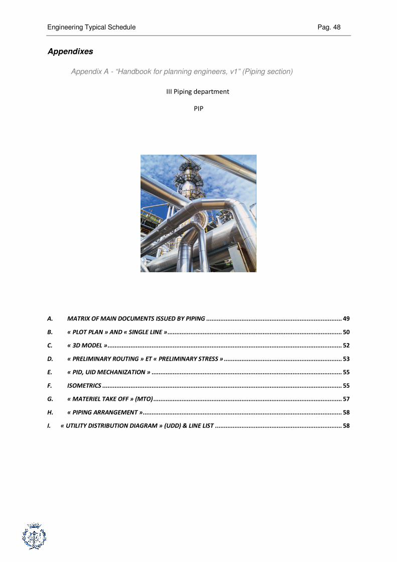
Appendix A - “Handbook for planning engineers, v1” (Piping section)
III Piping department
PIP
A. MATRIX OF MAIN DOCUMENTS ISSUED BY PIPING ............................................................................. 49
B. « PLOT PLAN » AND « SINGLE LINE »................................................................................................... 50
C. « 3D MODEL »..................................................................................................................................... 52
D. « PRELIMINARY ROUTING » ET « PRELIMINARY STRESS » ................................................................... 53
E. « PID, UID MECHANIZATION » ............................................................................................................ 55
F. ISOMETRICS ........................................................................................................................................ 55
G. « MATERIEL TAKE OFF » (MTO)........................................................................................................... 57
H. « PIPING ARRANGEMENT »................................................................................................................. 58
I. « UTILITY DISTRIBUTION DIAGRAM » (UDD) & LINE LIST ........................................................................ 58
Engineering Typical Schedule Pag. 49
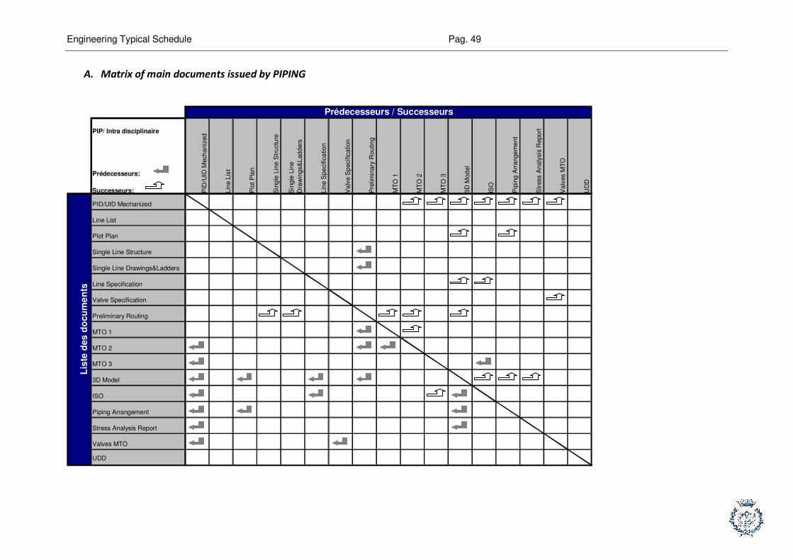
A. Matrix of main documents issued by PIPING
PIP/ Intra disciplinaire
Prédecesseurs:
Successeurs: PID
/UID
Mech
aniz
ed
Lin
e L
ist
Plo
t P
lan
Sin
gle
Lin
e S
tru
ctu
re
Sin
gle
Lin
e
Dra
win
gs&
Lad
ders
Lin
e S
pe
cific
atio
n
Va
lve S
pecific
ation
Pre
limin
ary
Rou
tin
g
MT
O 1
MT
O 2
MT
O 3
3D
Mod
el
ISO
Pip
ing
Arr
an
ge
me
nt
Str
ess A
na
lysis
Re
po
rt
Va
lves M
TO
UD
D
PID/UID Mechanized
Line List
Plot Plan
Single Line Structure
Single Line Drawings&Ladders
Line Specification
Valve Specification
Preliminary Routing
MTO 1
MTO 2
MTO 3
3D Model
ISO
Piping Arrangement
Stress Analysis Report
Valves MTO
UDD
Lis
te d
es
do
cu
me
nts
Prédecesseurs / Successeurs
Engineering Typical Schedule Pag. 50
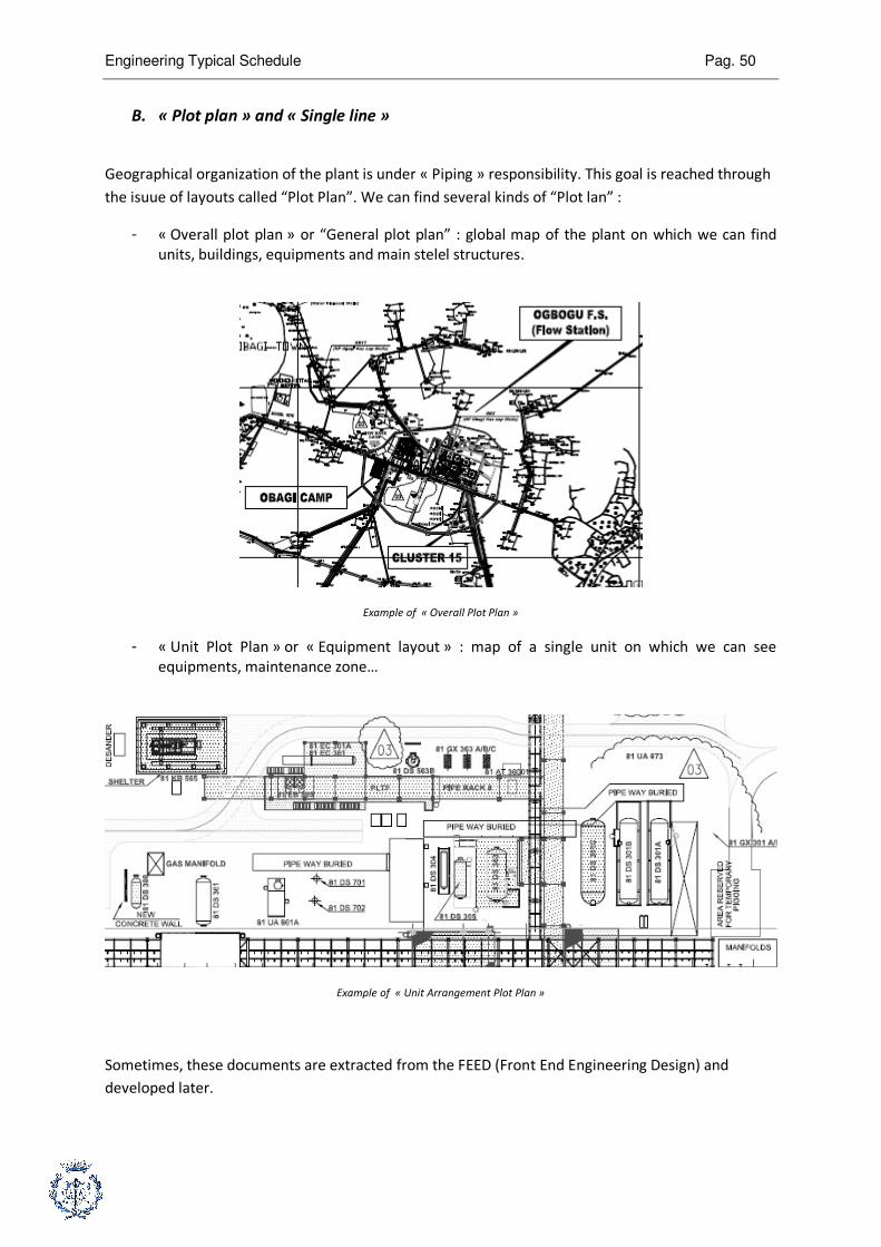
B. « Plot plan » and « Single line »
Geographical organization of the plant is under « Piping » responsibility. This goal is reached through
the isuue of layouts called “Plot Plan”. We can find several kinds of “Plot lan” :
- « Overall plot plan » or “General plot plan” : global map of the plant on which we can find
units, buildings, equipments and main stelel structures.
Example of « Overall Plot Plan »
- « Unit Plot Plan » or « Equipment layout » : map of a single unit on which we can see
equipments, maintenance zone…
Example of « Unit Arrangement Plot Plan »
Sometimes, these documents are extracted from the FEED (Front End Engineering Design) and
developed later.

Engineering Typical Schedule Pag. 51
« Key Plan » is a geographical breakdown of the plant designed from « Plot Plan ». “Key Plan” is an
input for the 3D model. “Piping” department has to make this document which is a necessary
document for other engineering departments.
Extrait d’un « Key Plan »
« Piping » department is responsible for the « Pipe Rack Single Line Diagram ». « Pipe Rack » is a
structure (steel or concrete) designed to support piping and cables. ”Piping” engineers design shape
of the racks and they estimate the loads on the rack. Then, these data are transferred to “Civil”
department who will design steel structure
Example of « Rack Single Line Drawings »
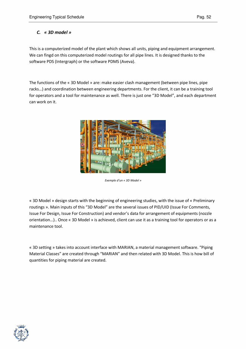
Engineering Typical Schedule Pag. 52
C. « 3D model »
This is a computerized model of the plant which shows all units, piping and equipment arrangement.
We can fingd on this computerized model routings for all pipe lines. It is designed thanks to the
software PDS (Intergraph) or the software PDMS (Aveva).
The functions of the « 3D Model » are: make easier clash management (between pipe lines, pipe
racks…) and coordination between engineering departments. For the client, it can be a training tool
for operators and a tool for maintenance as well. There is just one “3D Model”, and each department
can work on it.
Exemple d’un « 3D Model »
« 3D Model » design starts with the beginning of engineering studies, with the issue of « Preliminary
routings ». Main inputs of this “3D Model” are the several issues of PID/UID (Issue For Comments,
Issue For Design, Issue For Construction) and vendor’s data for arrangement of equipments (nozzle
orientation…).. Once « 3D Model » is achieved, client can use it as a training tool for operators or as a
maintenance tool.
« 3D setting » takes into account interface with MARIAN, a material management software. “Piping
Material Classes” are created through “MARIAN” and then related with 3D Model. This is how bill of
quantities for piping material are created.
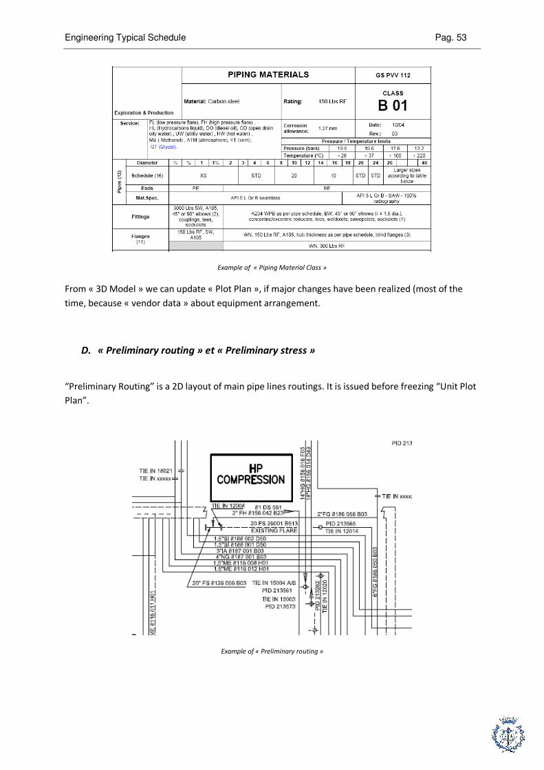
Engineering Typical Schedule Pag. 53
Example of « Piping Material Class »
From « 3D Model » we can update « Plot Plan », if major changes have been realized (most of the
time, because « vendor data » about equipment arrangement.
D. « Preliminary routing » et « Preliminary stress »
“Preliminary Routing” is a 2D layout of main pipe lines routings. It is issued before freezing “Unit Plot
Plan”.
Example of « Preliminary routing »

Engineering Typical Schedule Pag. 54
« Preliminary Routings » can impact « Structure Single Line drawings » and activities from “Civil”
department. Once “Preliminary routings” are converted into “3D Model”, this computerized model
will be the basis of piping stress studies. First routings realized are “Underground routings”.
« Preliminary stress » studies are useful to freeze routings for main critical pipe lines. These studies
depend on design factors like fluid temperature, fluid pressure, snow, wind...
« Preliminary routings » and « Preliminary stress analysis » are linked.
For example, stress calculation can impose expansion loops on a piping line. An expansion loop
avoids irreversible deformation and risk of fracture of piping, due to dilatation or shrinkage (fluid
temperature variation).
Schéma et exemple de lyre

Engineering Typical Schedule Pag. 55
E. « PID, UID mechanization »
« PID/UID Mechanization » is the step of engineering when each department (Piping,
Instrumentation, Equipment) adds its own comment on PID/UID. « Process » department is
responsible for this activity. PIP adds into PID data from « Plot Plan », bill of quantities…
F. Isometrics
An « Isometric » is a 3D layout useful for piping pre fabrication. This document is quoted but it is not
a scale drawing. It is extracted from the “3D Model”. We can find on these layouts specific
information for piping erection. The only relevant status for an isometric drawing is “Issue For
Construction”.
Extrait d’un « Isometric Drawing »
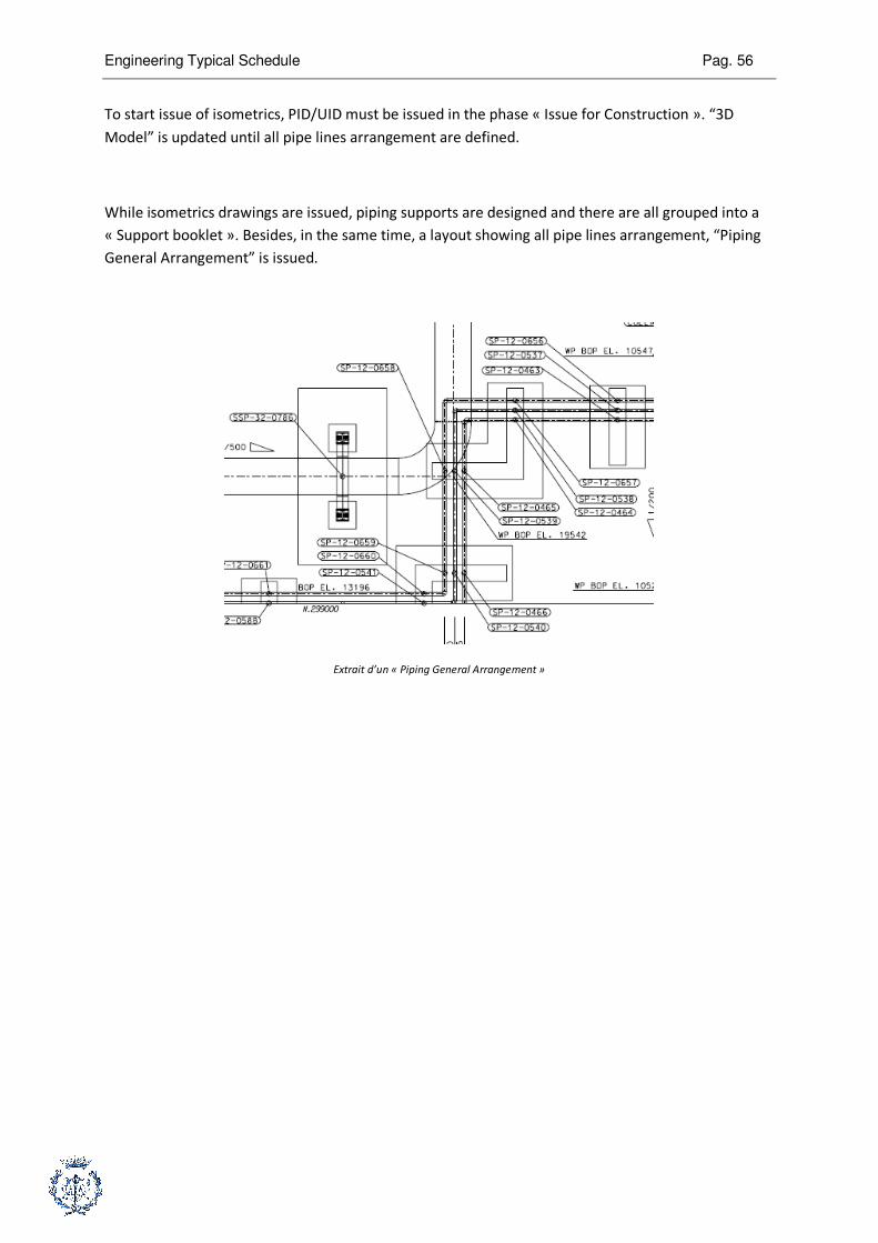
Engineering Typical Schedule Pag. 56
To start issue of isometrics, PID/UID must be issued in the phase « Issue for Construction ». “3D
Model” is updated until all pipe lines arrangement are defined.
While isometrics drawings are issued, piping supports are designed and there are all grouped into a
« Support booklet ». Besides, in the same time, a layout showing all pipe lines arrangement, “Piping
General Arrangement” is issued.
Extrait d’un « Piping General Arrangement »

Engineering Typical Schedule Pag. 57
G. « Materiel Take Off » (MTO)
A « Material Take Off » is a bill of quantities for bulk material (material which is not itemized like
cables, pipe lines, steel structure…). These “bill of quantities” are useful to start « Invitation to bid »,
to issue “Purchase orders” and to manage quantities. Manual valves are considered as “Bulk
material”. Basically, there are three steps for this activity, which last about 15 months.
To make the first MTO, PID/UID “Issue for Approval” are required. For example, we can find on it
how many manual valves are necessary for process loops. To quantify piping material, “Preliminary
routings” are required.
To update the first MTO (and issue MTO2), second issue of PID/UID (PID/UID Issue For Design) and an
update of preliminary routings are required.
Average required time to realize a « Material Take Off » is two months. The last issue of « Material
Take Off » requires much more time because it is based on isometrics drawings issue.
PID/UID IFA
Preliminary routing
Ou
MTO 1
MTO 1 Updated Check b file MTO 2
3D Model ISO MTO 3

Engineering Typical Schedule Pag. 58
H. « Piping Arrangement »
Once « Plot Plan » and « 3D Model » have been issued, « Piping » department has to design “Piping
Arrangement”. This document is required for piping erection on field.
Besides, « Piping department » has to design piping supports, valves, ladders and secondary
structures.
I. « Utility Distribution Diagram » (UDD) & line list
The goal of this activity is design utilities distribution network. Its inputs are PID/UID from process..
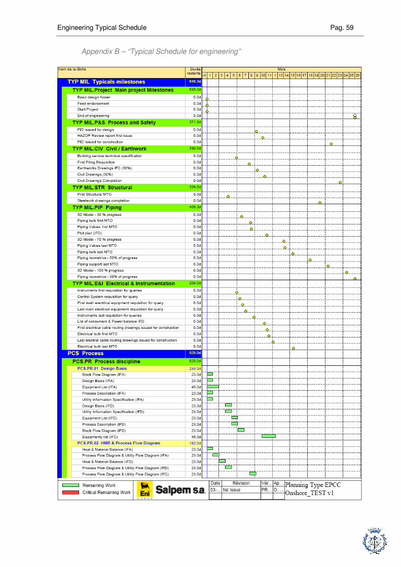
Engineering Typical Schedule Pag. 59
Appendix B – “Typical Schedule for engineering”
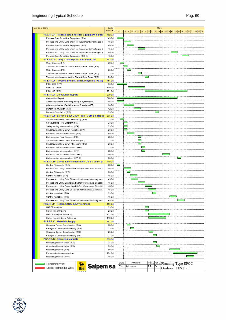
Engineering Typical Schedule Pag. 60
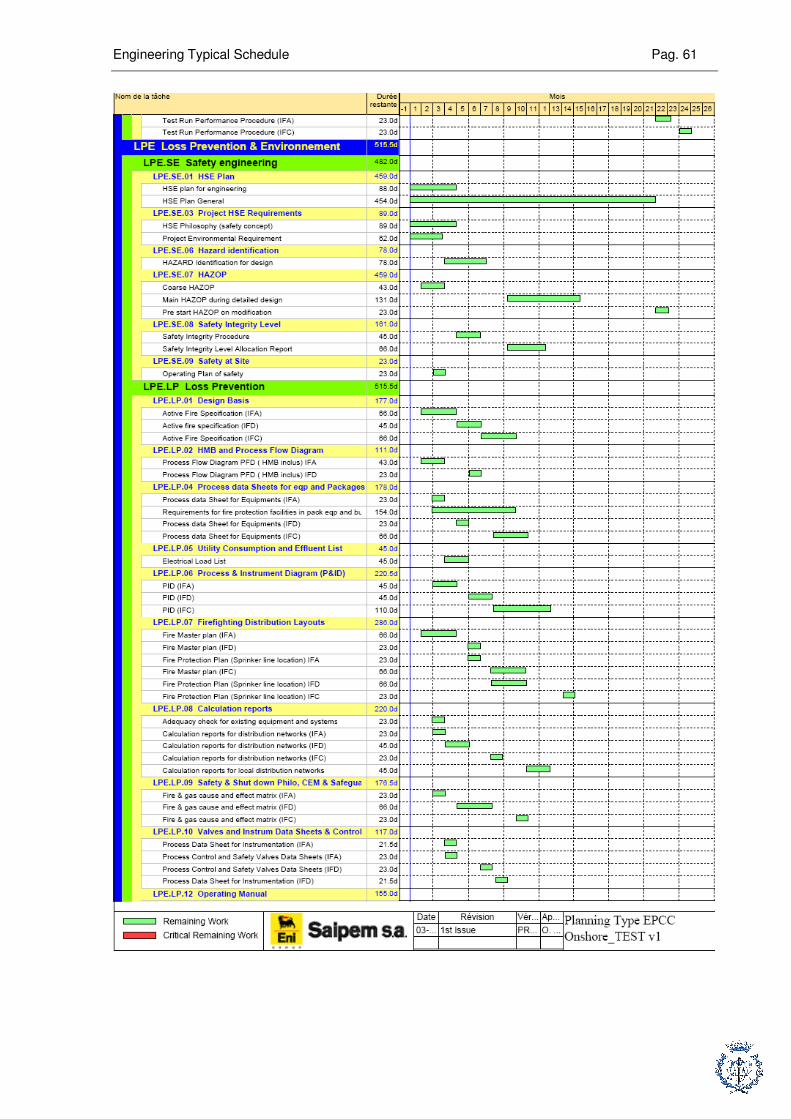
Engineering Typical Schedule Pag. 61

Engineering Typical Schedule Pag. 62
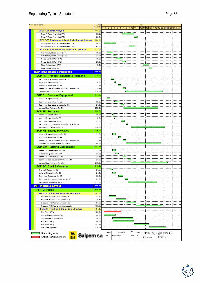
Engineering Typical Schedule Pag. 63
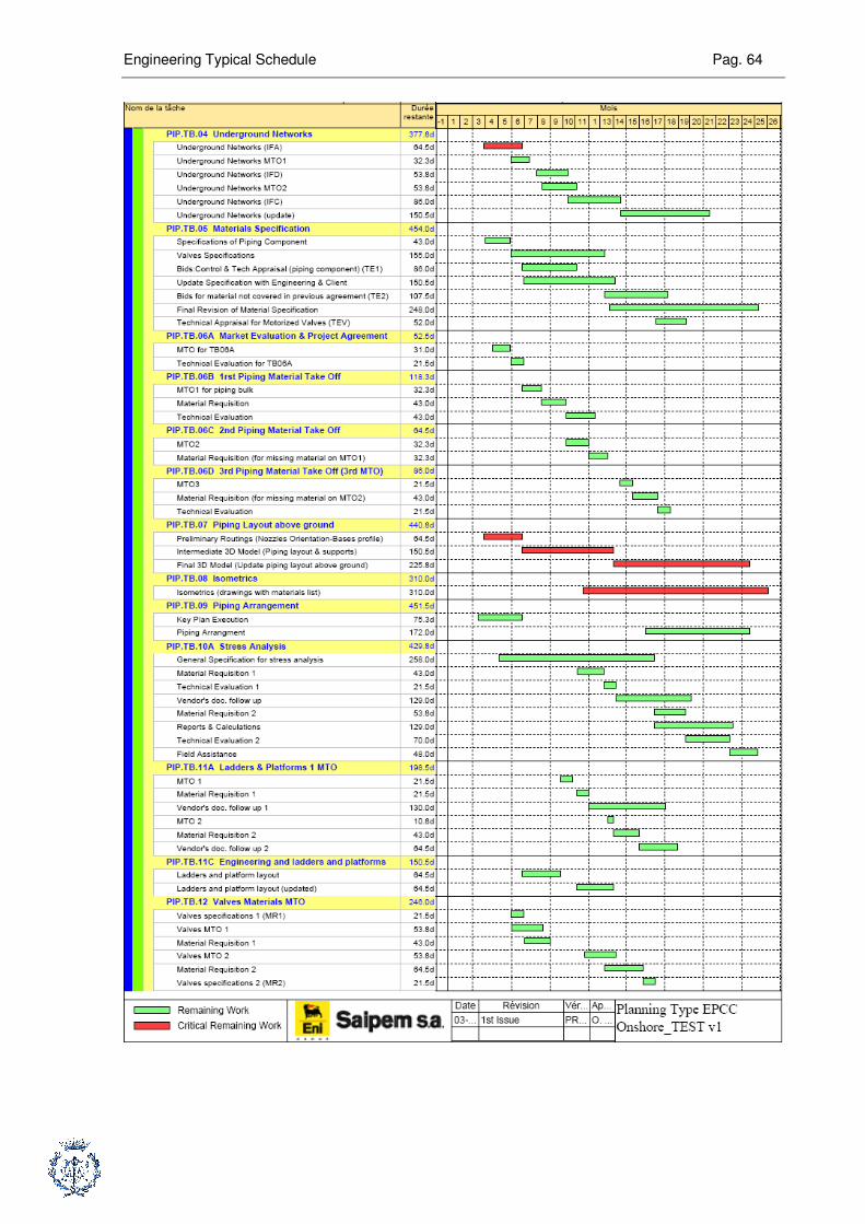
Engineering Typical Schedule Pag. 64
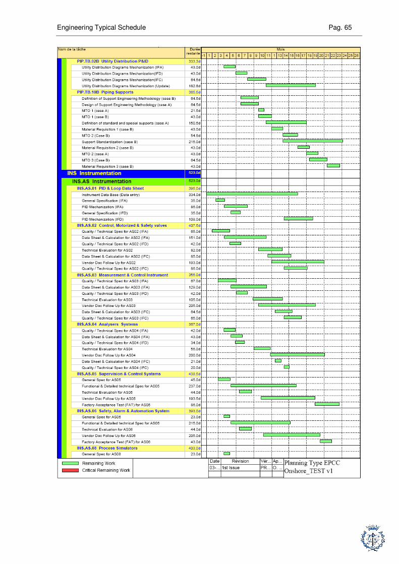
Engineering Typical Schedule Pag. 65
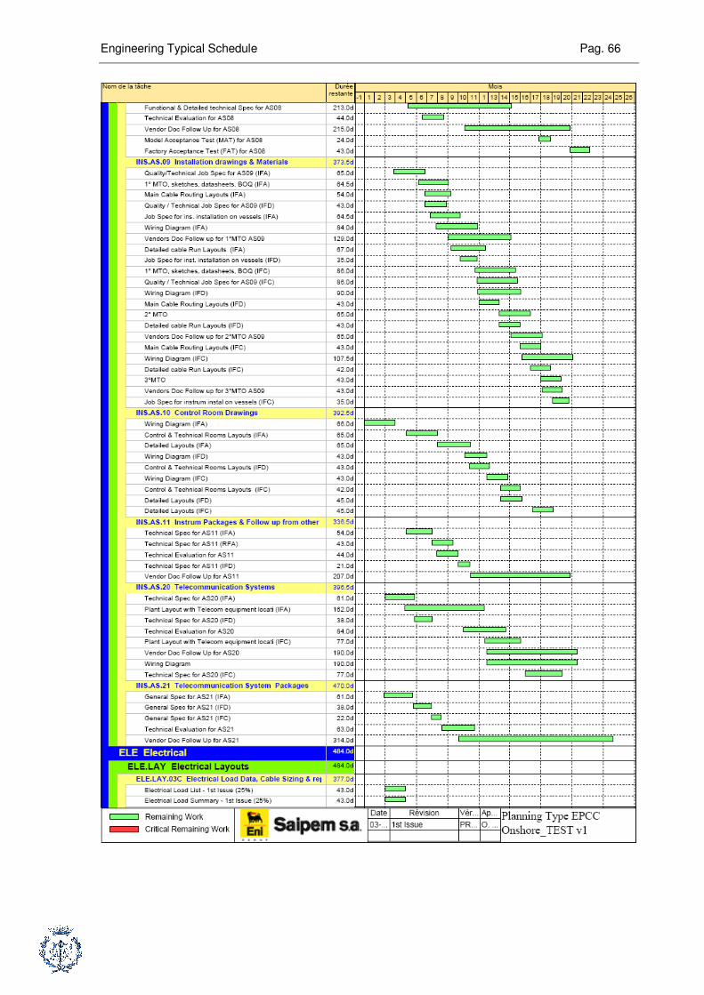
Engineering Typical Schedule Pag. 66
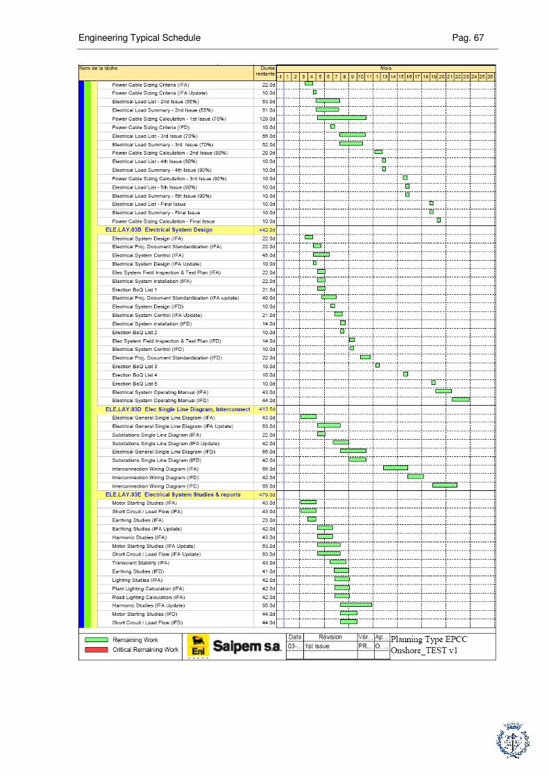
Engineering Typical Schedule Pag. 67

Engineering Typical Schedule Pag. 68
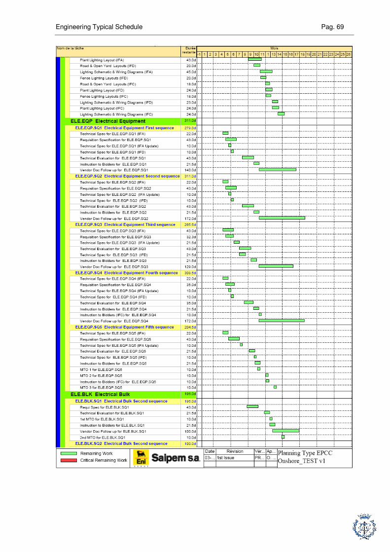
Engineering Typical Schedule Pag. 69

Engineering Typical Schedule Pag. 70
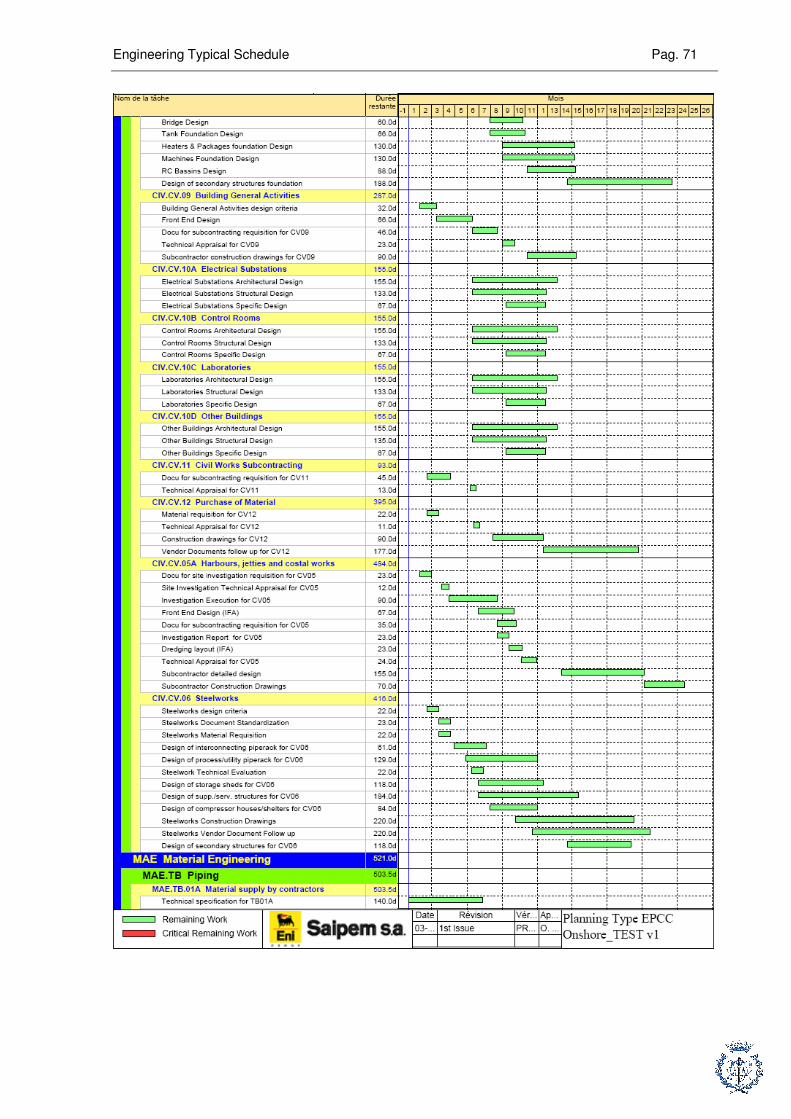
Engineering Typical Schedule Pag. 71

Engineering Typical Schedule Pag. 72

Engineering Typical Schedule Pag. 73
Bibliography
RAOULT, F, Handbook for planning engineers, v0, Corporate document
Engineering Management Class, Corporate document
Primavera Project Planner version 3.0, Reference Manual, Primavera Systems,Inc