Abstract (a) (b) - University of...
6
Abstract—The design of master manipulators for master-slave surgical robotic systems is important because it may influence slave manipulator performance as well as the operator’s workload. However, no design strategy has been presented thus far for optimizing the master manipulator design parameters. A master manipulator prototype and an experimental setup were developed for investigating design parameter influence using our master-slave microsurgical robotic system. The preliminary results showed that the relative position of the holding point, the corresponding point for the slave manipulator’s working point, and the center of the gimbals are important for master manipulator design, especially for tasks requiring large or frequent posture changes. The experimental results also suggested that the optimized parameters would contribute to enhancing task efficiency and decreasing the workload, rather than increasing task accuracy. I. INTRODUCTION ASTER –slave robotic systems have been employed in surgical robotics for enhancing surgeons‟ dexterity as well as enabling motion scaling. The most famous surgical robotic system, the “da Vinci Surgical System,” has its own master manipulator design, facilitating intuitive manipulation of the slave robotic arms. Many research groups have also tried to design their original master manipulators or used available haptic devices [1]; however, to the best of the present authors‟ knowledge, there is no design strategy for surgical master manipulators. Master manipulator design affects system usability, the slave manipulators‟ motion accuracy, and operator workload. Further, it is obvious that better master manipulator design facilitates the introduction of surgical robots to clinical cases. Moreover, master manipulator design may depend on the target clinical applications or tasks, and thus, a design theory is required. The research focus in laparoscopy has been on the enhancement of dexterity and usability as well as the implementation of haptics, rather than the enhancement of accuracy, and thus, many research groups use commercial haptic devices such as the PHANTOM series (SensAble, Manuscript received on January 31, 2012. Y. Kamei, S. Tanaka, K. Harada, Y. Baek, Y. Ida, N. Sugita and M. Mitsuishi are with the Department of Mechanical Engineering, The University of Tokyo, Bunkyo-ku, Tokyo 113-8656 Japan (Tel. and Fax: +81-3-5841-6357; e-mail: kanako@ nml.t.u-tokyo.ac.jp). S. Sora is with the Department of Neurosurgery, Tokyo Metropolitan Police Hospital, Nakano-ku, Tokyo 164-8541 Japan. A. Morita is with the Department of Neurosurgery, NTT Medical Center Tokyo, Shinagawa-ku, Tokyo 141-8625 Japan. USA) (for example, in [2], as shown in Fig. 1(a)) and the Delta/Omega/Sigma series (Force Dimension, Switzerland) (for example, in [3], as shown in Fig. 1(b)). There are also several original designs using the Delta structure [1, 4]. Meanwhile, accuracy and precision are of the utmost importance in microsurgery. For example, microsurgical robots for neurosurgery need to perform very fine and complex tasks such as the anastomosis of 0.7 mm blood vessels. Although there are several neurosurgical robotic systems [5-8], their target applications are limited to simple tasks such as needle insertion and tumor removal. Hence, the usability of master manipulators for complicated tasks remains to be established. Microsurgical robots include eye surgery robots (for example, the eye surgery robot reported in [9]). However, no complex tasks require to be performed in an eye surgery. Consequently, we have focused on the usability of a master manipulator, especially for micro neurosurgical robots having six degrees of freedom (DoFs), with the three positioning DoFs decoupled from the three orientational DoFs. In this work, the design parameters of surgical master manipulators were investigated using a microsurgical robotic system in order to clarify the unique microsurgery features that need to be considered in the design of master-slave surgical robots. Master manipulator prototypes were designed by attaching a mechanism to a commercial haptic device in order to vary the design parameters. Experiments were conducted in order to quantify the effects of design parameters on the robot performance and workload. The paper is organized as follows. The prototype design is described in Section II, and Section III details the experimental setup and method. Section IV reports the experimental results, and the paper is concluded in Section V. (a) (b) (c) (d) Fig. 1. Master manipulators for surgical robotic systems. (a) Raven [2], (b) DLR MiroSurge [3], (c) NeuroArm [5], and (d) Brain Tumor Removal Robot System [6]. Study on Master Manipulator Design Parameters for Robotic Microsurgery Y. Kamei, Student Member, IEEE, S. Tanaka, Student Member, IEEE, K. Harada, Member, IEEE, Y. Baek, Student Member, IEEE, Y. Ida, S. Sora, A. Morita, N. Sugita, and M. Mitsuishi, Member, IEEE M The Fourth IEEE RAS/EMBS International Conference on Biomedical Robotics and Biomechatronics Roma, Italy. June 24-27, 2012 978-1-4577-1198-5/12/$26.00 ©2012 IEEE 847
Transcript of Abstract (a) (b) - University of...
Abstract—The design of master manipulators for master-slave
surgical robotic systems is important because it may influence
slave manipulator performance as well as the operator’s
workload. However, no design strategy has been presented thus
far for optimizing the master manipulator design parameters. A
master manipulator prototype and an experimental setup were
developed for investigating design parameter influence using our
master-slave microsurgical robotic system. The preliminary
results showed that the relative position of the holding point, the
corresponding point for the slave manipulator’s working point,
and the center of the gimbals are important for master
manipulator design, especially for tasks requiring large or
frequent posture changes. The experimental results also
suggested that the optimized parameters would contribute to
enhancing task efficiency and decreasing the workload, rather
than increasing task accuracy.
I. INTRODUCTION
ASTER –slave robotic systems have been employed in
surgical robotics for enhancing surgeons‟ dexterity as
well as enabling motion scaling. The most famous surgical
robotic system, the “da Vinci Surgical System,” has its own
master manipulator design, facilitating intuitive manipulation
of the slave robotic arms. Many research groups have also
tried to design their original master manipulators or used
available haptic devices [1]; however, to the best of the
present authors‟ knowledge, there is no design strategy for
surgical master manipulators. Master manipulator design
affects system usability, the slave manipulators‟ motion
accuracy, and operator workload. Further, it is obvious that
better master manipulator design facilitates the introduction of
surgical robots to clinical cases. Moreover, master
manipulator design may depend on the target clinical
applications or tasks, and thus, a design theory is required.
The research focus in laparoscopy has been on the
enhancement of dexterity and usability as well as the
implementation of haptics, rather than the enhancement of
accuracy, and thus, many research groups use commercial
haptic devices such as the PHANTOM series (SensAble,
Manuscript received on January 31, 2012.
Y. Kamei, S. Tanaka, K. Harada, Y. Baek, Y. Ida, N. Sugita and M.
Mitsuishi are with the Department of Mechanical Engineering, The
University of Tokyo, Bunkyo-ku, Tokyo 113-8656 Japan (Tel. and Fax:
+81-3-5841-6357; e-mail: kanako@ nml.t.u-tokyo.ac.jp).
S. Sora is with the Department of Neurosurgery, Tokyo Metropolitan Police
Hospital, Nakano-ku, Tokyo 164-8541 Japan.
A. Morita is with the Department of Neurosurgery, NTT Medical Center
Tokyo, Shinagawa-ku, Tokyo 141-8625 Japan.
USA) (for example, in [2], as shown in Fig. 1(a)) and the
Delta/Omega/Sigma series (Force Dimension, Switzerland)
(for example, in [3], as shown in Fig. 1(b)). There are also
several original designs using the Delta structure [1, 4].
Meanwhile, accuracy and precision are of the utmost
importance in microsurgery. For example, microsurgical
robots for neurosurgery need to perform very fine and
complex tasks such as the anastomosis of 0.7 mm blood
vessels. Although there are several neurosurgical robotic
systems [5-8], their target applications are limited to simple
tasks such as needle insertion and tumor removal. Hence, the
usability of master manipulators for complicated tasks
remains to be established. Microsurgical robots include eye
surgery robots (for example, the eye surgery robot reported in
[9]). However, no complex tasks require to be performed in an
eye surgery. Consequently, we have focused on the usability
of a master manipulator, especially for micro neurosurgical
robots having six degrees of freedom (DoFs), with the three
positioning DoFs decoupled from the three orientational
DoFs.
In this work, the design parameters of surgical master
manipulators were investigated using a microsurgical robotic
system in order to clarify the unique microsurgery features
that need to be considered in the design of master-slave
surgical robots. Master manipulator prototypes were designed
by attaching a mechanism to a commercial haptic device in
order to vary the design parameters. Experiments were
conducted in order to quantify the effects of design parameters
on the robot performance and workload.
The paper is organized as follows. The prototype design is
described in Section II, and Section III details the
experimental setup and method. Section IV reports the
experimental results, and the paper is concluded in Section V.
(a) (b)
(c) (d)
Fig. 1. Master manipulators for surgical robotic systems. (a) Raven [2], (b)
DLR MiroSurge [3], (c) NeuroArm [5], and (d) Brain Tumor Removal Robot
System [6].
Study on Master Manipulator Design Parameters
for Robotic Microsurgery
Y. Kamei, Student Member, IEEE, S. Tanaka, Student Member, IEEE, K. Harada, Member, IEEE,
Y. Baek, Student Member, IEEE, Y. Ida, S. Sora, A. Morita, N. Sugita, and M. Mitsuishi, Member, IEEE
M
The Fourth IEEE RAS/EMBS International Conferenceon Biomedical Robotics and BiomechatronicsRoma, Italy. June 24-27, 2012
978-1-4577-1198-5/12/$26.00 ©2012 IEEE 847

II. PROTOTYPING
A. Master-Slave Robotic System for Microsurgery
Master manipulator designs were investigated using our
master-slave microsurgical robotic system [10]. This system
was designed for both neurosurgery and eye surgery. The
anastomosis of 0.3 mm artificial blood vessels [11], which is a
very difficult manual operation, was demonstrated with the
system.
Figure 2 shows the master-slave microsurgical robotic
system overview. The operator (i.e., the surgeon) manipulates
two master arms while looking at the microscopic stereo view
provided on the 3D monitor. The slave robotic system is
composed of two robotic arms, each with six DoFs, and a
surgical tool unit with one gripping DoF is mounted onto each
arm. The surgical unit can be interchanged with another unit
based on the target clinical application or task. The
translational motion of the master manipulator is scaled down
and transmitted to the slave robot.
Microscope
Forceps
Orientation Component
Translation Component
SurgicalField
Microscopic View
3D monitor
Master manipulators
Stereo microscope
Surgical tool unit
Slave
manipulators
Surgical field
Microscopic view
Fig. 2. Master-slave microsurgical robotic system.
Human arm motion was previously quantified and the
master manipulators shown in Fig. 2 were designed [12]. The
master manipulator employed a pen-like gripper because the
manner in which a pen is held, called a tripod grip, is similar to
the manner in which a pair of surgical tweezers is held in
microsurgery. Figure 3 (a) shows the manner in which a pair
of tweezers is held, where C is the working point, H is the
holding point, and O is the approximate center of rotation. The
gripper of the master manipulator (Fig. 3(b)) was designed to
replicate these relative positions; the hand grasping point, H,
was approximately 30 mm from the gimbal center, O, whereas
the point, C, to which the slave robot‟s tip corresponded was
set 80 mm from the gimbal center, O.
H
C
O
H C
O
(a) (b)
Fig. 3. The manner in which a pair of surgical tweezers is held. C is the
working point, H is the holding point, and O is the center of revolution.
Surgeons were not satisfied with the usability of the master
manipulators, regardless of the similarity of the gripping pose,
although the dexterity was sufficient to perform a complicated
task with high precision. It was also difficult for us to identify
which design parameters to change because the design process
was not systematic. Therefore, the design process was
reviewed. In many master manipulators reported in literature,
the working point of a surgical tool, xc′, (Fig. 4(a)) is
correlated to the center of the gimbals, O, (Fig. 4(b)) of the
master manipulator. For example, in the x-coordinate whose
origin was set at the gimbal center (Fig.4 (b)), the
corresponding slave manipulator position coincides with the
origin (xc = 0) and the surgeon holds the proximal side of the
gripper (xh < 0). Both the holding and corresponding points
were set at the distal side of the gripper (xc > xh > 0) in our
previous master manipulator design, as shown in Fig.4 (c). It
seems that the configuration shown in Fig. 4 (b) is more
intuitive, whereas the configuration in Fig. 4(c) was designed
to replicate the actual holding position used in microsurgery.
Therefore, the ways in which the similarity to the actual
surgical situation may affect the performance and workload in
a robotic microsurgery scenario were investigated. A
prototype of the master manipulator was designed in order to
quantify the influence of the design parameters xc and xh.
xc‟
x
xc
O
xh
xxc
xh
O
(a) (c)(b)
Fig. 4. Master-slave position correspondence. (a) Working point of the
surgical tool mounted on the slave manipulator, (b) Corresponding and
holding points of the master manipulator in [5], and (c) Corresponding and
holding points of the master manipulator of the master-slave microsurgical
robotic system [12].
B. Master manipulator prototype design
A PHANTOM Omni device (SensAble, USA) was used to
measure the positioning DoFs (three DoFs) and a gimbal
mechanism with a stylus was attached in order to measure the
orientation DoFs (three DoFs), as shown in Fig. 5. The
original gimbals of the PHANTOM Omni were glued and
fixed. The advantage of using a commercial device is that the
results can be shared with the research community and used
for the design of a new manipulator for a master-slave surgical
robotic system.
Three miniature encoders with a resolution of 0.0225°
(MES-9-1000PST16E, Microtech Laboratory Inc., Japan)
were implemented in the gimbals and provided higher pose
measurement accuracy in comparison to the original
PHANTOM Omni gimbals. This was necessary in order to
avoid the effect of the relatively low angular resolution of the
original gimbals on slave manipulator performance. The
pen-like stylus was attached to the gimbal structure, which
848

provides more configurable holding point positions. The
holding point, xh, is a mechanical design parameter, whereas
the corresponding point, xc, is a parameter to be set in the
control program.
Fig. 5. Master manipulator for the experiment. (a) PHANTOM Omni
(SensAble, USA), (b) Gimbals with a stylus.
III. EXPERIMENTS
A. Experimental Setup
The experimental setup is shown in Fig. 6 and the system
overview is shown in Fig. 7. The experiments were
performed for the right hand only because all subjects were
right-handed and used their right hands for needle
manipulation in microsurgery. The Libralis library [13] was
used for PHANTOM gravity compensation. The
communication between the master and slave systems was
updated at 100 Hz and the servo rate of the slave robotic
system was 1 kHz. The response was sufficient, and it was
assumed that slave performance and operator workload
were not influenced by the mechanical setup or control.
3D monitor
Stylus
Gimbals
PHANTOM
Omni®
Arm rest
Stereo Microscope
Slave
manipulator
(a) (b)
Fig. 6. Experimental setup. (a) Master system (b) Slave system.
3D monitor
RTLinux UDPWindows
100 Hz
Slave
manipulator
Stereo microscope Master
manipulator
Foot switch
FireWire USB
Pulse counter
Slave
system
Master
system
Arm rest
Fig. 7. Experimental setup: system configuration.
B. Design of Experiments
The microscopic magnification was set such that a 10 mm
circle could fit in the view. A 27 G needle with its tip painted
red was attached to the distal end of the surgical tool unit, and
the position of the needle was estimated and tracked using the
image processing method described in the next subsection.
The position of the tip of the needle was set to coincide with
that of the remote center of motion of the slave manipulator.
Three tasks were designed, namely, (1) a Tracing Task, (2)
a Pointing Task, and (3) a Posture-changing Task, as
illustrated in Fig. 9. The tasks were developed to contain some
of the motion elements required in microsurgical tasks. The
motion scaling ratio was set at 3x, which reflected a
neurosurgeon‟s opinion that the slave manipulators can be
intuitively maneuvered at the ratio in neurosurgical tasks. The
distance between the gimbal center and holding point Xh = –xh
and the distance between the corresponding point and holding
point Xc = xc xh were varied in the experiment, as shown in
Fig. 8. Twelve pairs of parameters (Xh = 20, 40, 60 mm and Xc
= 30, 0, 20, 60 mm) were tested in the preliminary
experiment. Two sets of twelve pairs were tested in random
order for each subject. Each subject was asked to keep his
forearm on the arm rest. In each task, the subject was asked to
provide a Subjective Score ranging from 1 (uncomfortable) to
10 (comfortable).
1) Tracing Task
This task was designed to examine the usability of the
master manipulator in the general position-changing
maneuvers. The subject traced a circle with a diameter of
10 mm in the tracing task. The circle was printed on a
piece of paper and the subject was asked to place the
needle tip as close as to the paper as possible. The task
completion time, RMS error, and the Subjective Score
were evaluated.
2) Pointing Task
The purpose of this task was to examine the usability in
precise targeting. The subject placed the needle tip in
small circles of 0.3 mm in diameter in the order of 0, 1, 0,
2, 0, 3, 0, 4, 0, as shown in Fig. 9 (b). The task
completion time, length of the trajectory, task
completion ratio, and Subjective Score were evaluated.
The trajectory length in 3D space was calculated from
the position of the corresponding master manipulator
point. Task completion evaluation success was defined
as the precise placement of the needle tip within each
small circle.
3) Posture-changing Task
This task was selected to evaluate the usability in
changing the slave manipulator posture while
maintaining the tip position. The subject aligned the
needle with the horizontal line starting from the line with
an angle of 45°, as shown in Fig. 9, and placed it back in
the original posture while keeping the needle tip at the
center of the cross. This set was repeated three times. The
task completion time, RMS error, and the Subjective
Score were evaluated.
(a) (b)
849

O
C
H
x Xc
Xh
Fig. 8. Coordinate system setting for the experiment.
10 mm
(a) (b) (c)
4
1
3
0
2
Fig. 9. Experimental tasks. (a) Tracing Task, (b) Pointing Task, and (c)
Posture-changing Task.
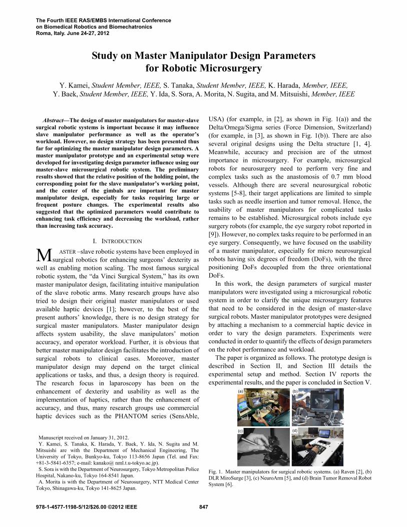
C. Tool tip detection
Image-based tool tip detection was developed and used to
obtain the position of the tip of the needle. The tracked
position was used to calculate the RMS error in the three
tasks mentioned in the previous subsection. As mentioned
above, the needle tip was painted red to simplify the
required image processing. It was easy to extract the red
color region in the HSV image space (consisting of hue,
saturation, and intensity) in the designed experimental setup
because the background color was white. The extracted red
colored region was converted to a binary image and the tool
tip was estimated by detecting the upper and lower contours
of the region.
Figure 10 shows an example of tool tip detection. The
binary image was generated by extracting the red colored
region in the microscopic image using predefined thresholds
for the hue and saturation values. The intensity value was
not used in the experiment because it was prone to error
because of the specular effect observed in the obtained
microscopic image. Next, several sets of two points were
aligned to the upper and lower contours of the extracted
region with a preset interval in order to find the lateral
contours of the needle. Thereafter, upper and lower contour
lines were generated by calculating the coefficients based on
the least square estimation. The tool tip point was defined as
the left-most point of the region located on the centerline of
the two contour lines. The tip position was tracked at a rate
of 30 Hz, with measurement accuracies of <50 m RMS.
Although there remains scope for improvement in the
detection accuracy, it was assumed to be sufficient for
master manipulator design parameter analysis.
Fig. 10. Example of tool tip detection: (a) input microscopic image, (b)
binary image of the red-colored tool region, (c) control points for the upper
and lower contours, and (d) line detection and tool tip estimation.
D. Statistical Analysis
The statistical significance of the differences in the
parameter sets was analyzed by a repeated-measures analysis
of variance (ANOVA) with two within-subject factors (Xh and
Xc), followed by post hoc analysis (Sidak‟s multiple
comparison test based on the estimated marginal means). The
statistical difference was accepted at p < 0.05. The
Greenhouse-Geisser method was used to adjust the degrees of
freedom, where appropriate. All statistical analyses were
conducted using Version 20 of SPSS Statistics (IBM, USA).
IV. RESULTS
A. Subjects
Two medical doctors and eight Engineering students
participated in the experiments.
B. Tracing Task
The ANOVA revealed significant main effects of factor Xc
on the Subjective Score (F(3, 27) = 7.313, p < 0.05), whereas
the main effects of factor Xh and the interaction Xh Xc on the
Subjective Score were not significant. The Sidak-corrected
pairwise comparisons revealed higher Subjective Scores for
Xc = 0 or 20 mm than for Xc = 30 mm (p < 0.05) (Fig. 11, left).
With regard to the RMS error, only the main effects of factor
Xh were significant (F(2, 18) = 4.456, p < 0.05). However, no
significant differences were revealed after multiple
comparisons of the error in each value of Xh, (Fig.11, right).
With respect to the task completion time, none of the main
effects of the factors was detected (data not shown).
1
2
3
4
5
6
7
8
9
10
-30 0 20 60
Su
bje
cti
ve S
co
re
Xc (mm)
*
*
0
50
100
150
200
250
300
350
400
450
500
20 40 60
RM
S E
rro
r (
m)
Xh (mm) Fig. 11. Tracing task result. Left: Estimated marginal means of the
Subjective Score for Xc. Bars indicate the standard errors. The asterisk (*)
indicates a pair with a significant difference (p < 0.05). Right: Estimated
marginal means of the RMS Error for Xh.
C. Pointing Task
The ANOVA revealed significant main effects of factors Xc
(F(1.476, 13.281) = 10.222, p < 0.05) and Xh (F(2, 18) =
4.868, p < 0.05) on the Subjective Score, whereas the main
effects of the interaction Xh Xc were not significant. Pairwise
comparisons revealed higher Subjective Scores for Xc = 0 and
60 mm than for Xc = 30 mm (p < 0.05) (Fig. 12, left). It was
also revealed that the Subjective Score for Xh = 20 mm was
higher than that for Xh = 60 mm (p < 0.05) (Fig. 12, right).
With regard to the task completion time, the significant main
effects of the factors Xc (F(3, 27) = 15.656, p < 0.001) and Xh
(a) (b) (c) (d)
850

(F(2, 18) = 6.755, p < 0.05) were revealed, whereas the main
effects of the interaction Xh Xc were not significant. Multiple
comparisons revealed shorter task completion times for Xc = 0,
20, and 60 mm in comparison to those for Xc = 30 mm (p <
0.05) (Fig. 13, left). Additionally, a shorter task completion
time was observed for Xh = 40 mm compared with Xh = 60 mm
(p < 0.05) (Fig. 13, right). Concerning the task completion rate
(Fig. 14), the significant main effects of factor Xc (F(3, 27) =
3.035, p < 0.05) were revealed, whereas no other main effects
were detected. The subsequent comparison test did not detect
any statistically significant differences in task completion
rates for Xc. No significant main factor effects were detected in
the lengths of the trajectories.
1
2
3
4
5
6
7
8
9
10
-30 0 20 60
Su
bje
cti
ve
Sco
re
Xc (mm)
**
1
2
3
4
5
6
7
8
9
10
20 40 60
Su
bje
cti
ve
Sco
re
Xh (mm)
*
Fig. 12. Subjective Score for the pointing task. Left: Estimated marginal
means of the Subjective Score for Xc. Right: Estimated marginal means of the
Subjective Score for Xh. Bars indicate the standard errors. The asterisk (*)
indicates a pair with a significant difference (p < 0.05).
0
5
10
15
20
25
30
-30 0 20 60
Ta
sk
Co
mp
leti
on
Tim
e (
s)
Xc (mm)
**
*
0
5
10
15
20
25
30
20 40 60
Ta
sk
Co
mp
leti
on
Tim
e (
s)
Xh (mm)
*
Fig. 13. Task completion time for the pointing task. Left: Estimated marginal
means of the task completion time for Xc. Right: Estimated marginal means
of the task completion time for Xh. Bars indicate the standard errors. The
asterisk (*) indicates a pair with a significant difference (p < 0.05).
0
10
20
30
40
50
60
70
80
90
100
-30 0 20 60
Task C
om
ple
tio
n R
ate
(%
)
Xc (mm) Fig. 14. Task completion rate of the pointing task. Estimated marginal
means for task completion rate according to the value of Xc. Bars indicate the
standard errors. No significant differences are observed.
D. Posture-changing Task
The ANOVA revealed significant main effects of factor Xc
(F(3, 27) = 7.293, p < 0.05) and the interaction Xh Xc (F(6,
54) = 7.451, p < 0.05) on the Subjective Score, whereas the
main effects of factor Xh were not significant. Fig. 15 (left)
shows the estimated marginal means for Xc at three Xh levels,
whereas Fig. 15 (right) shows the estimated marginal means
for Xh at four Xc levels. Regarding the task completion time,
the main effects of factor Xc (F(1.439, 12.951) = 6.696, p <
0.05) and the interaction Xh Xc (F(2.584, 23.255) = 3.831, p
< 0.05) were significant, whereas no significant main effects
were detected for factor Xh. The results of the multiple
comparison tests are shown in Fig. 16.
1
2
3
4
5
6
7
8
9
10
-30 0 20 60
Su
bje
cti
ve S
co
re
Xc (mm)
20 40 60
*
Xh (mm)
*
*
1
2
3
4
5
6
7
8
9
10
20 40 60
Su
bje
cti
ve S
co
re
Xh (mm)
-30 0 20 60** *
**
Xc (mm)
Fig. 15. Subjective Score for the posture-changing task. Left: Estimated
marginal means of the Subjective Score for Xc. Right: Estimated marginal
means of the Subjective Score for Xh. Bars indicate the standard errors. The
asterisk (*) indicates a pair with a significant difference (p < 0.05).
0
5
10
15
20
25
30
-30 0 20 60
Task C
om
ple
tio
n T
ime (
s)
Xc (mm)
20 40 60
Xh (mm) *
0
5
10
15
20
25
30
20 40 60
Task C
om
ple
tio
n T
ime (
s)
Xh (mm)
-30 0 20 60
Xc (mm)
** *
Fig. 16. Task completion time for the posture-changing task. Left: Estimated
marginal means of the task completion time for Xc. Right: Estimated
marginal means of the task completion time for Xh. Bars indicate the standard
errors. The asterisk (*) indicates a pair with a significant difference (p <
0.05).
E. Summary of Experimental Results
Table I summarizes the experimental results, including the
results that are not explained in detail in the previous
subsection.
The performance of the slave manipulator in terms of
accuracy was not influenced by the relative position of the
holding point, corresponding point, and the center of the
gimbals. The efficiency of the tasks, which was measured as
the task completion time or trajectory length, was influenced
by the relative positions for the pointing task and the posture
changing task, and this was probably because both tasks
required bigger or more frequent posture changes, which can
851

be more affected by the master manipulator design. The
Subjective Score was influenced in most cases.
The result of the preliminary experiment suggested that the
accuracy of the slave robot could be somehow independent of
the mechanical design of the master manipulator, though the
efficiency of the task and the operator workload could be
influenced by the design parameters, especially for tasks
requiring large or frequent posture changes.
Although more data should be collected for further
investigation of the optimal design parameters, it was clarified
that the relative position of the holding point, corresponding
point, and the center of the gimbals are important for master
manipulator design for microsurgery, especially for enhancing
usability.
TABLE I Summary of the experiments: The significant influence of the
parameters on each task; (a) the corresponding point should coincide with the
holding point or be located at its distal side; (b) the holding point should be
closer to the gimbal center; (c) the influence is proved, although the suitable
parameter setting remains unclear; (d) the corresponding point should
coincide with the holding point or be placed closer to the holding point at its
distal side.
1) Tracing 2) Pointing 3) Posture-changing
N Y (b) Y (c)
Efficiency N Y (b) Y (c)
Accuracy N N N
Y (a) Y (a) Y (d)
Efficiency N Y (a) Y (d)
Accuracy N N N
X h
Subjective Score
Performance
X c
Subjective Score
Performance
V. CONCLUSION
We developed a master manipulator prototype in order to
investigate the master manipulator design parameters for
microsurgery. The preliminary results showed that the relative
position of the holding point, corresponding point, and the
center of the gimbals are important for master manipulator
design for microsurgery, especially for enhancing usability.
The future work will include experiments with greater
parameter variance in order to systematically define the
design parameters.
ACKNOWLEDGMENT
This study was partially supported by the Global Center of
Excellence for Mechanical Systems Innovation (GMSI) at the
University of Tokyo and a Grant-in-Aid for Scientific
Research (S) 23226006.
REFERENCES
[1] J. Arata, H. Kondo, M. Sakaguchi, and H. Fujimoto, “Development of a
haptic device „DELTA-4‟ using parallel link mechanism,” in
International Conference Robotics and Automation (ICRA), pp.
294-300, 2009.
[2] G. Sankaranarayanan et al., “Portable surgery master station for mobile
robotic telesurgery,” in Proceedings of the 1st International
Conference on Robot Communication and Coordination, p. 28, 2007.
[3] U. Hagn et al., “DLR MiroSurge: a versatile system for research in
endoscopic telesurgery.,” International journal of computer assisted
radiology and surgery, vol. 5, no. 2, pp. 183-93, Mar. 2010.
[4] K. Tadano and K. Kawashima, “Development of a master slave system
with force sensing using pneumatic servo system for laparoscopic
surgery,” in Robotics and Automation, pp. 10-14, 2007.
[5] A. D. Greer, P. M. Newhook, and G. R. Sutherland, “Human–machine
interface for robotic surgery and stereotaxy,” Mechatronics,
IEEE/ASME Transactions on Mechatronics, vol. 13, no. 3, pp.
355-361, 2008.
[6] M. Takagi, T. Wada, J. Arata, Y. Hayashi, Y. Kajita, and H. Fujimoto,
“Development of Surgical Cockpit for Brain Tumor Removal Robot
System,” in the JSME Conference on Robotics and Mechatronics,
2011.
[7] K. Hongo, Y. Kakizawa, and J. Koyama, “Microscopic-manipulator
system for minimally invasive neurosurgery: preliminary study for
clinical application,” International Congress Series, vol. 1230, pp.
275-280, 2001.
[8] P. Eldridge, “Use of the NeuroMate stereotactic robot in a frameless
mode for functional neurosurgery,” The International Journal of
Medical Robotics and Computer Assisted Surgery, pp. 107-113, 2006.
[9] H. C. M. Meenink, R. H. P. C. J. N. Rosielle, M. Steinbuch, H.
Nijmeijer, and M. C. D. Smet, “A master-µslave robot for vitreo-retinal
eye surgery,” in The Euspen International Conference, Delft, 2010.
[10] Y. Ida, N. Sugita, T. Ueta, Y. Tamaki, K. Tanimoto, and M. Mitsuishi,
“Microsurgical robotic system for vitreoretinal surgery,” International
journal of computer assisted radiology and surgery, vol. 7, no. 1, pp.
27-34, Jan. 2012.
[11] Y. M. Baek et al., “Highly precise master-slave robot system for super
micro surgery,” 2010 3rd IEEE RAS & EMBS International
Conference on Biomedical Robotics and Biomechatronics, pp.
740-745, Sep. 2010.
[12] H. Takahashi, T. Yonemura, N. Sugita, and M. Mitsuishi, “Master
manipulator with higher operability designed for micro neuro surgical
system,” IEEE International Conference on Robotics and Automation
(ICRA 2008), pp. 3902-3907, 2008.
[13] A. Formaglio, M. Fei, S. Mulatto, M. de Pascale, and D. Prattichizzo,
“Autocalibrated gravity compensation for 3DoF impedance haptic
devices,” Haptics: Perception, Devices and Scenarios, pp. 43-52,
2008.
852