Abstract 1 Motivation - gatech.edu
13
X-Analysis Integration Technology Russell S. Peak Technical Report EL002-2000A Engineering Information Systems Lab http://eislab.gatech.edu/ CALS Technology Center Georgia Institute of Technology Atlanta, Georgia USA March 15, 2000 Abstract This document overviews X-analysis integration (XAI) technology and example applications. It serves as a guide to recent research and development in this arena carried out by EIS Lab. References to in-depth descriptions of the underlying concepts and applications are included in an annotated bibliography. 1 Motivation Linking design and analysis models is profoundly different than typical data integration tasks in that it requires multidirectional heterogeneous transformations - transforming one or more types of information (e.g., design geometry and materials) into a different type of information (e.g., an idealized finite element model) and vice-versa. Today such idealization transformations are usually not articulated in any form, much less captured as computable CAD-CAE associativity (Figure 4a), thus seriously limiting automation and knowledge capture. The integration challenge is further complicated in that a given type of product can have numerous types of analysis models that vary in discipline, resolution, application, and fidelity [Peak 1993; Peak et al. 1998]. We believe this diversity makes the gap between design and analysis too large for a single span integration bridge. 2 Technical Approach 2.1 MRA Conceptual Architecture The multi-representation architecture (MRA) has been developed with intermediate representations as stepping stones to achieve the flexibility and modularity dictated by the above simulation-based engineering (SBE) needs (Figure 1). It is particularly aimed at capturing reusable analysis knowledge at the preliminary and detailed design stages. In the MRA conceptual architecture, solution method models (SMMs) are object-oriented wrappers around detailed solution tools that obtain analysis results in a highly automated manner. They support white box reuse of existing tools (e.g., FEA tools and in-house codes) within an integrated framework (Figure 5, Figure 8). Analysis building blocks (ABBs) represent analytical engineering concepts as semantically rich objects independent of solution method and product domain. ABBs generate SMMs based on solution technique-specific considerations such as symmetry and mesh density. Analyzable product models (APMs) represent design-oriented details, providing a common stepping stone to multiple design tools and supporting multi-fidelity analysis idealizations [Tamburini, 1999]. Finally, context-based analysis models
Transcript of Abstract 1 Motivation - gatech.edu
X-Analysis Integration TechnologyRussell S. Peak
Technical Report EL002-2000A
Engineering Information Systems Labhttp://eislab.gatech.edu/
CALS Technology CenterGeorgia Institute of Technology
Atlanta, Georgia USA
March 15, 2000
AbstractThis document overviews X-analysis integration (XAI) technology and example applications. It serves as aguide to recent research and development in this arena carried out by EIS Lab. References to in-depthdescriptions of the underlying concepts and applications are included in an annotated bibliography.
1 MotivationLinking design and analysis models is profoundly different than typical data integration tasks in that itrequires multidirectional heterogeneous transformations - transforming one or more types of information(e.g., design geometry and materials) into a different type of information (e.g., an idealized finite elementmodel) and vice-versa. Today such idealization transformations are usually not articulated in any form,much less captured as computable CAD-CAE associativity (Figure 4a), thus seriously limiting automationand knowledge capture. The integration challenge is further complicated in that a given type of product canhave numerous types of analysis models that vary in discipline, resolution, application, and fidelity [Peak1993; Peak et al. 1998]. We believe this diversity makes the gap between design and analysis too large fora single span integration bridge.
2 Technical Approach
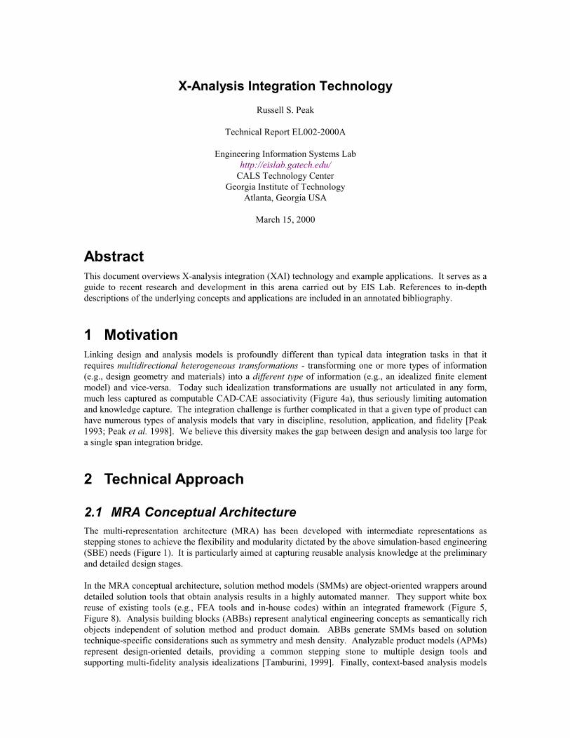
2.1 MRA Conceptual ArchitectureThe multi-representation architecture (MRA) has been developed with intermediate representations asstepping stones to achieve the flexibility and modularity dictated by the above simulation-based engineering(SBE) needs (Figure 1). It is particularly aimed at capturing reusable analysis knowledge at the preliminaryand detailed design stages.
In the MRA conceptual architecture, solution method models (SMMs) are object-oriented wrappers arounddetailed solution tools that obtain analysis results in a highly automated manner. They support white boxreuse of existing tools (e.g., FEA tools and in-house codes) within an integrated framework (Figure 5,Figure 8). Analysis building blocks (ABBs) represent analytical engineering concepts as semantically richobjects independent of solution method and product domain. ABBs generate SMMs based on solutiontechnique-specific considerations such as symmetry and mesh density. Analyzable product models (APMs)represent design-oriented details, providing a common stepping stone to multiple design tools andsupporting multi-fidelity analysis idealizations [Tamburini, 1999]. Finally, context-based analysis models
X-Analysis Integration Technology
2
(CBAMs) explicitly represent the fine-grained associativity between a design model and its diverse analysismodels (i.e., between ABBs and APMs). CBAMs are also known as analysis modules and analysistemplates.
Figure 1 illustrates these concepts via a solder joint analysis example [Peak et al. 1998]. Due to thecoefficient of thermal expansion mismatch between the printing wiring board (PWB) and component, thesolder joint deforms under thermal loads. The goal of this analysis model is to compute the resulting strainin order to estimate solder joint fatigue life. The left side shows design-related details of APM entities: thecross-section of a component, a PWB, solder joints, and epoxy. The assembly of these entities is anotherAPM entity, a PWA component occurrence, ωc. On the right, the ABB is a generic analysis system, PlaneStrain Bodies System, that can be used in analyses for multiple types of products.
The CBAM, Solder Joint Plane Strain Model, contains associativity linkages, Φi, which indicatehow the APM design entities are idealized as homogeneous plane strain bodies in the ABB. For example,linkage Φ1 explicitly specifies that the height of ABB body1, h1, equals the total height of the component, hc
(a geometric idealization, Γ1, of the detailed APM component entity). Linkage Φ2 similarly specifies thematerial model for body1. While the top figure shows this design-analysis associativity informally, thelower one is a constraint schematic - a structured information model that specifies all associativity linkages.As COBs, these such product-specific analysis models also have underlying lexical forms.
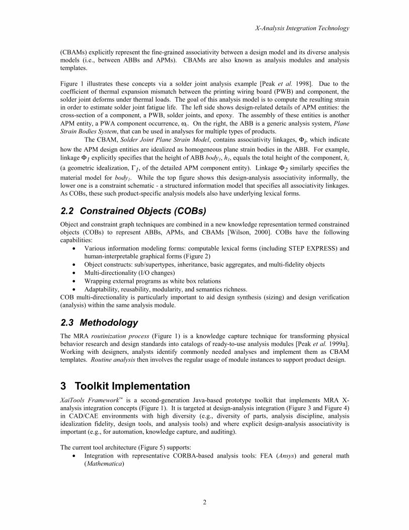
2.2 Constrained Objects (COBs)Object and constraint graph techniques are combined in a new knowledge representation termed constrainedobjects (COBs) to represent ABBs, APMs, and CBAMs [Wilson, 2000]. COBs have the followingcapabilities:
• Various information modeling forms: computable lexical forms (including STEP EXPRESS) andhuman-interpretable graphical forms (Figure 2)
• Object constructs: sub/supertypes, inheritance, basic aggregates, and multi-fidelity objects• Multi-directionality (I/O changes)• Wrapping external programs as white box relations• Adaptability, reusability, modularity, and semantics richness.
COB multi-directionality is particularly important to aid design synthesis (sizing) and design verification(analysis) within the same analysis module.
2.3 MethodologyThe MRA routinization process (Figure 1) is a knowledge capture technique for transforming physicalbehavior research and design standards into catalogs of ready-to-use analysis modules [Peak et al. 1999a].Working with designers, analysts identify commonly needed analyses and implement them as CBAMtemplates. Routine analysis then involves the regular usage of module instances to support product design.
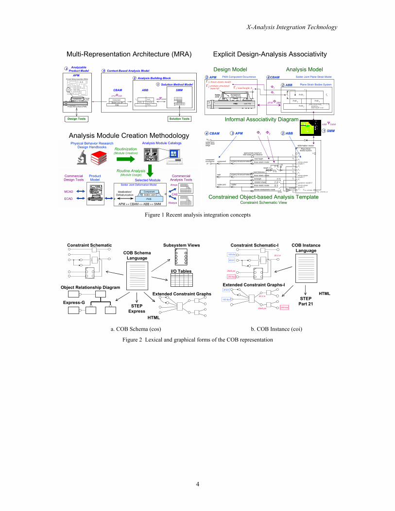
3 Toolkit ImplementationXaiTools Framework™ is a second-generation Java-based prototype toolkit that implements MRA X-analysis integration concepts (Figure 1). It is targeted at design-analysis integration (Figure 3 and Figure 4)in CAD/CAE environments with high diversity (e.g., diversity of parts, analysis discipline, analysisidealization fidelity, design tools, and analysis tools) and where explicit design-analysis associativity isimportant (e.g., for automation, knowledge capture, and auditing).
The current tool architecture (Figure 5) supports:• Integration with representative CORBA-based analysis tools: FEA (Ansys) and general math
(Mathematica)

X-Analysis Integration Technology
3
• Integration with representative design tools: mechanical CAD (CATIA), electrical CAD (via STEPAP210 DIS WD1.7), custom tools, and libraries (e.g., materials and fasteners)
• COB-based analysis module libraries• Basic COB authoring tools• Multi-directional constraint solver: COB-based wrapper for Mathematica
4 Applications & BenefitsExample industrial applications include PWA-B thermomechanical analysis, electronic packaging thermalresistance analysis, and aerospace structural analysis (Figure 3, Figure 4, Figure 6) [Peak et al. 1997, 1999c,2000a]. Product-specific applications such as XaiTools PWA-B™ and XaiTools ChipPackage™ have beenbuilt upon this general-purpose foundation. In a nutshell product-specific CBAMs and product modelentities (APMs) are added as COB subclasses. Related techniques [Koo, 2000; Zhou et al. 1997]intelligently leverage product model knowledge to mesh and combine building blocks into complex finiteelement models - models that are often impractical with brute force automeshing (Figure 4).
Distinctive benefits include greater than 10:1 reduction in analysis modeling time, highly automatedparametric FEA, self-serve analysis for supply chains at Internet-based engineering service bureaus (ESBs)(Figure 7, Figure 8) [Scholand et al. 1999], capture of multi-fidelity multi-directional reusable analysisknowledge, and standards-based product data-driven analysis. Overall the MRA approach has divided theCAD-CAE gulf into natural object-oriented packages coupled with explicit associativity to fundamentallyaddress the integration issues identified above.
5 Further ResearchCurrent research includes MRA-based optimization [Cimtalay, 2000], simulation-based manufacturing[Scholand, 2000], generalized product data-driven finite element meshing, and advanced geometricidealization associativity. Other research directions include:• Advanced constrained object constructs (e.g., higher order constraints, subgraph buffering, general
aggregate relations, and time domain attributes)• Multi-level inter-analysis associativity and related conditions and loads that originate from product
requirements• Techniques and tools for interactively constructing and using COBs in multi-user environments• Automated pullable views combining documentation languages like XML and COB techniques (e.g., to
show results summaries)
X-Analysis Integration Technology
4
Multi-Representation Architecture (MRA)
1 Solution Method Model
ΨABB SMM
2 Analysis Building Block
4 Context-Based Analysis Model3
SMMABBΦAPM ABB
CBAM
APM
Design Tools Solution Tools
Printed Wiring Assembly (PWA)
Solder Joint
Component
PWB
body3body2
body1body4
T0
Printed Wiring Board (PWB)
SolderJointComponent
AnalyzableProduct Model
Explicit Design-Analysis Associativity
Analysis Module Creation Methodology
ProductModel Selected Module
Analysis Module Catalogs
MCAD
ECAD
Physical Behavior ResearchDesign Handbooks
CommercialAnalysis ToolsAnsys
Abaqus
Solder Joint Deformation Model
Idealization/Defeaturization
CommercialDesign Tools
PWB
Solder JointComponent
APM ↔ CBAM ↔ ABB=↔ SMM
Routine Analysis(Module Usage)
Routinization(Module Creation)
CAE
Informal Associativity Diagram
Constrained Object-based Analysis TemplateConstraint Schematic View
Plane Strain Bodies System
PWA Component Occurrence
CL
1
νmaterial ,E( α, )geometry
body
plane strain body , i = 1...4PWB
SolderJoint
Epoxy
Componentbase: Alumina
core: FR4
Solder Joint Plane Strain Model
total height, h
linear-elastic model
Φ1
Φ2
APM ΦABB
Γ1:
Γ3:3 APM 4 CBAM
2 ABBc
4body 3body
2body
1h oT
primary structural material
Γ2:
ii
i
1 SMM
Design Model Analysis Model
ABB ΨSMM
soldersolder joint
pwb
component
1.25
deformation model
total height
detailed shape
rectangle
[1.2]
[1.1]
average
[2.2]
[2.1]
ω cTc
Ts
inter-solder joint distanceapproximate maximum
∆γsj
L s
primary structural materialtotal thickness
linear-elastic model
Plane Strain
geometry model 3
a
stress-strainmodel 1
stress-strainmodel 2
stress-strainmodel 3
Bodies System
γ xy, extreme, 3
T2
L1
T1
T0
L2
h1
h2
T3Tsj
hs
hc
L c
γ xy, extreme, sjbilinear-elastoplastic model
linear-elastic model
primary structural material linear-elastic modelcomponentoccurrence
solder jointshear strainrange
[1.2]
[1.1]length 2 +
3 APM 2 ABBΦ2Φ14 CBAM
Figure 1 Recent analysis integration concepts
Subsystem Views
Object Relationship Diagram
COB SchemaLanguage
I/O Tables
Extended Constraint Graphs
Constraint Schematic
STEPExpress
Express-G
HTML
COB InstanceLanguage
Extended Constraint Graphs-I
Constraint Schematic-I
STEPPart 21
200 lbs
30e6 psi
100 lbs 20.2 in
R101
R101
100 lbs
30e6 psi 200 lbs
20.2 inHTML
a. COB Schema (cos) b. COB Instance (coi)
Figure 2 Lexical and graphical forms of the COB representation
X-Analysis Integration Technology
5
Analysis Modules (CBAMs) of Diverse Mode & Fidelity MCAD Tools
Materials DB
y
xPP
E, A
∆LLeff
ε=, σ=
L
FEA Ansys
General MathMathematica
Analyzable Product Model
XaiTools
XaiTools
Extension
Torsion1D
1D,2D,3D*
Modular, Reusable Template Libraries
CATIA
temperature change,=∆T
material model
temperature, T reference temperature, To
cte, α
youngs modulus, E
force, F
area, A stress,=σ
undeformed length, Lo
strain,=ε
total elongation,=∆Llength, L
start, x1
end, x2
mv6
mv5
smv1
mv1mv4
E
α
One D LinearElastic Model
(no shear)
∆T
εσ
εe
εt
thermal strain, εt
elastic strain, εe
mv3
mv2
xFF
E, A, α
∆LLo
∆T, ε=, σ=
yL
r1
r2
r4
sr1
r3
material
effe ctive len gth , Lef f
deforma tio n mode l
li near elastic mode l
Lo
Torsional Rod
G
ϕ
τ
J
γ
r
θ2
θ1
she ar modulus, G
cross sectio n:e ffecti ve rin g polar moment of inertia, J
al1
al3
a l2a
lin ka ge
mode: sha ft torsion
condition rea ctionT
outer radius, r o a l2b
stress mo s model
allo wable stre ss
twist mos mod el
Margin of Safety(> case)
allowableactual
MS
Ma rg in of Safety(> case)
allowableactual
MS
allow abletw ist Analysis Tools
* = Item not yet available in toolkit (all others have working examples)
Design Tools
a. Tutorial examples: “flap link” mechanical part
Analysis Tools
0. 4375 in
0. 5240 in
0. 0000 in
2.440 in
1.267 in
0.307 in
0.5 in
0.310 in
2.088 in
1.770 in
67000 ps i
65000 ps i
57000 ps i
52000 ps i
39000 ps i
0.067 in/in
0.030 in/in
5960 I bs
1
10000000 ps i
9.17
5. 11
9. 77
rear spar fit ting att ach point
BLE7K18
2G7T12U (D et ent 0, Fairing Condition 1)
L29 -300
Outboard TE Flap, Support N o 2;Inboard Beam, 123L4567
Bulk head Fitti ng Joint
Program
Part
Feature
Channel Fit tingStatic Strengt h AnalysisTemplate
1 of 1D ataset
strength model
r 1
eb
h
tb
te
Pu
Ftu
E
r2
r0
a
FtuL T
Ft y
FtyLT
epuLT
tw
MSwall
epu
jm
MSepb
MSeps
Ch annel FittingSta tic Stre ngth Ana lysis
Fsu
IAS Functi onRef D6-81766
end pad
base
material
wall
analysi s context
mode: (ulti mate stati c strength)
con diti on:
heuristic: overall fi tt ing factor, Jm
bolt
f itt ing
headradius, r1
hol e radius, ro
wid th, b
eccentri ci ty, ethickness, te
hei ght, h
rad ius, r2thickness, tb
hole
th ickness, twangl ed hei ght, a
max all owable ulti mate stress,
allowable ult imate long transverse stress,max all owable yi eld stress,max all owable long transverse stress,max all owable she ar stress,pl astic ul timate strai n,
pl astic ul timate strai n long tran sverse,young mod ulus of el asticity,
load, P u
Ft u
Fty
Ft yL T
Fsu
epu
epuL T
E
FtuL T
product structure (chann el f it ting joi nt) Analysis Modules (CBAMs)
of Diverse Feature:Mode, & Fidelity Design Tools
Materials DB
FEAElfini*
MATDB-like
Analyzable Product Model
XaiTools
XaiTools
Fitting:Bending/Shear
3D
1.5D
Modular, Reusable Template LibrariesMCAD Tools
CATIA
Lug:Axial/Oblique; Ultimate/Shear
1.5D
Assembly:Ultimate/
FailSafe/Fatigue** = Item not yet available in toolkit (all others have working examples)
di agonal brace l ug joint j = top
0.7500 in
0.35 in
0.7500 in
1.6000 in
2
0. 7433
14. 686 K
2.40
4.317 K
8.633 K
k = norm
Max. torque brake set tingdetent 30, θ2=3.5º
7050-T7452, MS 7-214
67 Ks i
L29 -300
Out board TE Flap, Support No 2;Inboard Beam, 123L4567
Diagonal Brace Lug Joint
Program
Part
Feature
Lug J ointAx ial Ultimate Strength Model
Template
j = top lugk = normal diamet er (1 of 4)
Dataset
materi al
deformation mo del
max a llowabl e ult imate stress, FtuL
e ffective width , W
anal ysis co ntext
objecti ve
mod e (ult imate static strength )
cond iti on
estimated axial ult imate strength
Marg in o f Safety(> case)
allowableactua l
MS
n ormal diameter, Dnorm
thickness, t
e dge margin, e
Plug joint
size,n
lug s
l ugj hole
diameters
product structure (lug j oi nt)
r1nP jointlug
L [ j:1,n ]
P lug
L [ k]Dk
o versize diameter, DoverD
PaxuWe
t
F t uax
Kaxu
Lug Axial Ulti mateStrength Model
BDM 6630
Fasteners DB
FASTDB-like
General Math Mathematica
In-HouseCodes
b. Aerospace examples: “bike frame” mechanical part
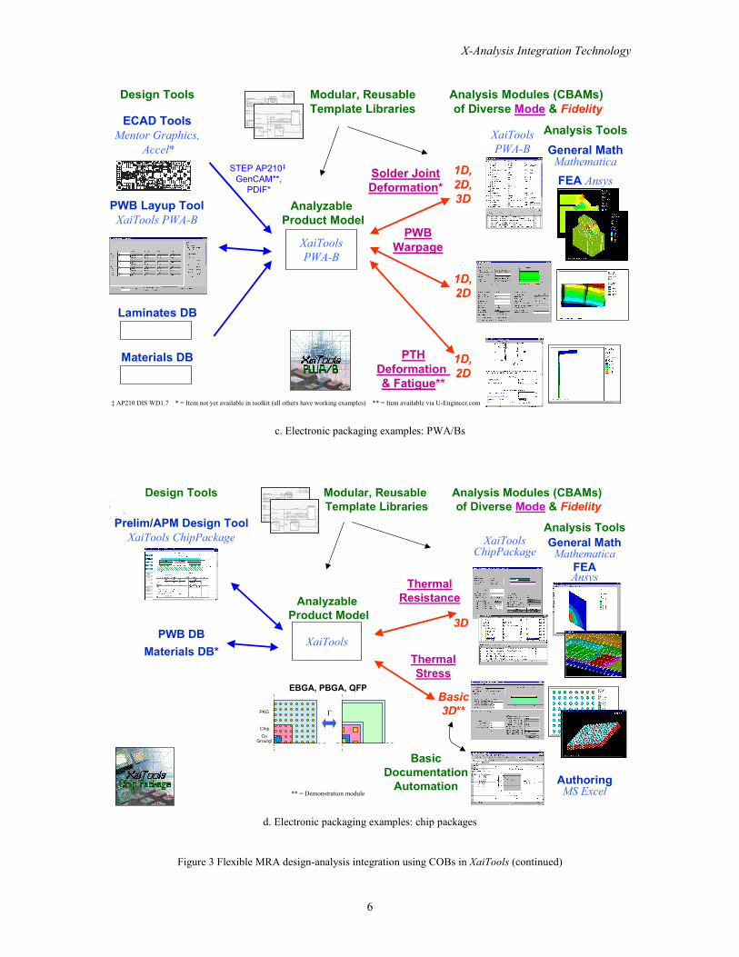
Figure 3 Flexible MRA design-analysis integration using COBs in XaiTools
X-Analysis Integration Technology
6
Analysis Modules (CBAMs) of Diverse Mode & Fidelity
Design Tools
Laminates DB
FEA Ansys
General MathMathematica
Analyzable Product Model
XaiToolsPWA-B
XaiToolsPWA-B
Solder JointDeformation*
PTHDeformation & Fatigue**
1D,2D
1D,2D,3D
Modular, ReusableTemplate Libraries
ECAD Tools Mentor Graphics,
Accel*
temperature change,=∆T
material model
temperature, T reference temperature, To
cte, α
youngs modulus, E
force, F
area, A stress,=σ
undeformed length, Lo
strain,=ε
total elongation,=∆L
length, Lstart, x1
end, x2
mv6
mv5
smv1
mv1mv4
E
α
One D LinearElastic Model
(no shear)
∆T
εσ
εe
εt
thermal strain, εt
elastic strain, εe
mv3
mv2
xFF
E, A, α
∆LLo
∆T, ε=, σ=
yL
r1
r2
r4
sr1
r3materia l
e ffecti ve length, Leff
deformation model
li near elastic mod el
Lo
Torsio nal Rod
G
ϕ
τ
J
γ
r
θ2
θ1
shear mo dulus, G
cross section:e ffective ring po lar momen t of in erti a, J
al1
al3
al2 a
linkage
mo de: shaft torsion
co ndition reactionT
ou ter radiu s, ro al2 b
stress mos mode l
allowable stress
tw ist mos mode l
Margin of Safety(> case)
allowableactual
MS
Margin of Safety(> case)
allowableactual
MS
allo wabletw ist Analysis Tools
PWBWarpage
1D,2D
Materials DB
PWB Layup ToolXaiTools PWA-B
STEP AP210‡ GenCAM**,
PDIF*
‡ AP210 DIS WD1.7 * = Item not yet available in toolkit (all others have working examples) ** = Item available via U-Engineer.com
c. Electronic packaging examples: PWA/Bs
EBGA, PBGA, QFP
CuGround
PKG
Chip
Γ
Analysis Modules (CBAMs) of Diverse Mode & Fidelity
FEAAnsys
General MathMathematica
Analyzable Product Model
XaiTools
XaiToolsChipPackage
ThermalResistance
3D
Modular, Reusable Template Librariestemperature change,=∆T
material model
temperature, T
reference temperature, To
cte, α
youngs modulus, E
force, F
area, A stress,=σ
undeformed length, Lo
strain,=ε
total elongation,=∆L
length, Lstart, x1
end, x2
mv6
mv5
smv1
mv1mv4
E
α
One D LinearElastic Model
(no shear)
∆T
εσ
εe
εt
thermal strain, εt
elastic strain, εe
mv3
mv2
xFF
E, A, α
∆LLo
∆T, ε=, σ=
yL
r112 xx −
r2
oLLL −=∆
r4
AF
sr1
oTT −
r3LL∆=ε
material
effe ctive length, Lef f
d eformation model
linear elastic model
Lo
Torsiona l Rod
G
ϕ
τ
J
γ
r
θ2
θ1
sh ear modulus, G
cross section:e ffective ring polar mo ment of inertia, J
al1
al3
al2a
li nkage
mode: shaft torsi on
condition reacti onT
outer radius, r o al2b
stress mos mod el
all owable stress
twist mos model
Margin of Safe ty(> case)
allowableactua l
MS
Marg in o f Sa fety(> ca se)
allowableactua l
MS
all owabletwist Analysis Tools
Design Tools
PWB DBMaterials DB*
Prelim/APM Design ToolXaiTools ChipPackage
ThermalStress
Basic3D**
** = Demonstration module
BasicDocumentation
Automation AuthoringMS Excel
d. Electronic packaging examples: chip packages
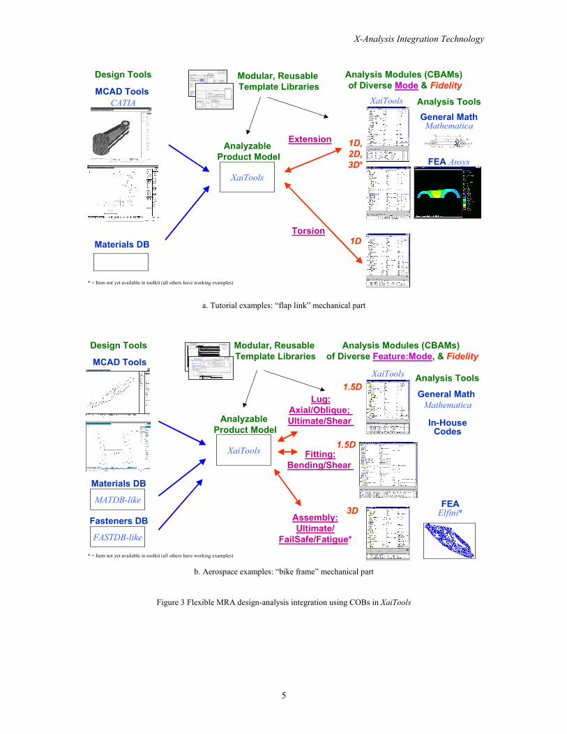
Figure 3 Flexible MRA design-analysis integration using COBs in XaiTools (continued)

X-Analysis Integration Technology
7
CAD Modelbulkhead assembly attach point
CAE Model channel fitting analysis
materialproperties
idealizedanalysis
geometry
analysisresults
No explicitfine-grainedCAD-CAE
associativity
detaileddesigngeometry
a. Representative current practice
Fitting Casing Body
Channel Fitting Casing Body*
Bathtub Fitting Casing Body
Angle FittingCasing Body
Fitting System ABB
Fitting Wall ABBFitting End Pad ABB
Fitting Bolt Body*
Open Wall FittingCasing Body
Fitting End Pad Bending ABB Fitting End Pad
Shear ABB*
Open Wall Fitting End Pad Bending ABB
Channel FittingEnd Pad Bending ABB*
ese
trPf02π
=
3 )2( b 1 teKC −=
21e
behtPCf =
21 1 KKC =
),,,( 011 erRrfK =
),(2 we ttfK =
),,( 13 hbrfK =π
baR+=
2dfRe
+−=
),min( wbwaw ttt =
bolt
load
Fitting Washer Body
Specialized Analysis Body
P
ABB
Specialized Analysis System
washercasing 0.4375 in
0.5240 in
0.0000 in
2.440 in
1.267 in
0.307 in
0.5 in
0.310 in
2.088 in
1.770 in
67000 psi
65000 psi
57000 psi
52000 psi
39000 psi
0.067 in/in
0.030 in/in
5960 Ibs
1
10000000 psi
9.17
5.11
9.77
bulkhead fitting attach point
LE7K18
2G7T12U (Detent 0, Fairing Condition 1)
L29 -300
Outboard TE Flap, Support No 2;Inboard Beam, 123L4567
Bulkhead Fitting Joint
Program
Part
Feature
Channel FittingStatic Strength Analysis
Template
1 of 1Dataset
strength model
r1
eb
h
tb
te
Pu
Ftu
E
r2
r0
a
FtuLT
Fty
FtyLT
epuLT
tw
MSwall
epu
jm
MSepb
MSeps
Channel FittingStatic Strength Analysis
Fsu
IAS FunctionRef DM 6-81766
end pad
base
material
wall
analysis context
mode: (ultimate static strength)
condition:
heuristic: overall fitting factor, Jm
bolt
fitting
headradius, r1
hole radius, ro
width, b
eccentricity, ethickness, teheight, h
radius, r2
thickness, tb
hole
thickness, twangled height, a
max allowable ultimate stress,
allowable ultimate long transverse stress,max allowable yield stress,
max allowable long transverse stress,max allowable shear stress,plastic ultimate strain,
plastic ultimate strain long transverse,young modulus of elasticity,
load, Pu
Ftu
Fty
FtyLTFsu
epu
epuLT
E
FtuLT
product structure (channel fitting joint)
ReusableChannel Fitting CBAM
Object Hierarchy ofFitting ABBs
b. Template Representation as COBs
Detailed CAD datafrom CATIA
Idealized analysis features in APM
Explicit multi-directional associativity between detailed CAD data & idealized analysis features
Fitting & MoS ABBs
Library data for materials & fasteners
c. Integrated implementation in MRA-based XaiTools
Figure 4 Aerospace analysis modules for channel fitting analysis

X-Analysis Integration Technology
8
ODBMS*, PDM*
Other CORBAWrappers*
MCAD: CATIAIDEAS*, Pro/E*, AutoCAD*
ECAD: Mentor Graphics (AP210 WD)PWB Layup ADT, ChipPackage ADT
Accel (PDIF, GenCAM)*
FEA: Ansys, Elfini*, Abaqus*Math: Mathematica, MatLab*, MathCAD*
In-House Codes
MaterialPropertyManager
ConstraintSolver
COB Schemas
objects, x.cos, x.exp
Analysis Module Tools
Mathematica
Template Libraries: Analysis Packages*, CBAMs, ABBs, APMs, Conditions*Instances: Usage/adaptation of templates
AnalysisCodes
COB Instances
objects, x.coi, x.step
Tool Forms(parameterized
tool models/full* SMMs)
CAD Tool
PersistentObject
Repository
Design Tools
COB Server
StandardParts
Manager
asterisk (*) = in-progress/envisioned extensions
Analysis Mgt. Tools
COB Analysis ToolsNavigator: XaiTools
Editor (text & graphical*)
Pullable Views*,Condition Mgr*, ...
CORBA Wrappers
Libraries
Figure 5 Product domain-independent XaiTools architecture
a. Ball grid array thermal resistance model[Koo, 2000; Peak et al. 2000a]
b. Ball grid array stress model[Zeng in Peak et al. 2000a]
c. PWB thermomechanical deformation model[Koo, 2000; Peak et al. 1999c]
c. PWA thermomechanical deformation model[Zhou et al. 1997]
Figure 6 Highly automated product data-driven finite element modeling

X-Analysis Integration Technology
9
Analysis Documentation Ready-to-Use Analysis ModulesFigure 7 U-Engineer.com - An Internet-based engineering service bureau (ESB)
Client PCs
XaiTools
Thick Client
UsersInternet
Current:U-Engineer.com(pilot demo) - Ansys - Mathematica
Future:Company Intranet and/orU-Engineer.com(commercial) - Other solvers
Iona orbixdj
Mathematica
Ansys
Internet/Intranet
XaiTools AnsysSolver Server
XaiTools AnsysSolver Server
XaiTools Math.Solver Server
CORBA Daemon
XaiTools AnsysSolver Server
FEA Solvers
Math Solvers
CORBA Servers
CO
RBA IIO
P...
Engineering Service BureauHost Machines
Figure 8 Automated execution of Internet/Intranet-based analysis solvers

X-Analysis Integration Technology
10
6 Bibliography
6.1 Engineering Change ManagementCohen, T.; Navathe, S. B.; Fulton, R.E (to appear 2000) C-FAR: Change Favorable Representation, InvitedPaper for Special Issue: “CAD After 2000: Integrated, Intelligent, Collaborative” CAD Journal.Cohen, T.; Peak, R.S.; Fulton, R.E. (Sept. 1999) Evaluating A Change Process Product Data Model For AnAnalysis Driven Supply Chain Case Study, 1999 ASME Design Engineering Technical Conferences,Proceedings of DETC99, Las Vegas, Nevada, 9014.Cohen, T.; Fulton, R.E. (1998) A Data Approach to Tracking and Evaluating Engineering Changes, 1998ASME Design Engineering Technical Conferences, Proceedings of DETC'98, Atlanta.Cohen, T. (1997) A Data Approach to Tracking and Evaluating Engineering Changes, Doctoral Thesis,Georgia Institute of Technology, Atlanta.
6.2 Analysis IntegrationThe following papers overview recent X-analysis integration (XAI) research and applications (includingelectronic packaging thermomechanical analysis and aerospace structural analysis). Most publications areaccessible on the web at http://eislab.gatech.edu/ along with other research, project, and toolkitinformation.
Other publications are planned describing newer developments (e.g., CBAMs) and applications(e.g., thermal resistance analysis for electronic chip packages). Advances beyond the main MRA paper[Peak et al. 1998] include:• APMs – Combine & filter design information from multiple sources and add idealizations that are
reusable in potentially many analyses (typically in CBAMs) [Tamburini, 1999]. Recognizes that thefull design-oriented PM is not typically required for analysis, thus simplifying APM management.
• CBAMs (context-based analysis models) – Generalizes PBAMs by adding associativity with the contextof why an analysis is being done, including objectives (e.g., determining margin of safety). PBAMsfocused on associativity between design objects (APM entities) and product-independent analysisobjects (ABBs). Other context elements under development include the requirements and behaviormodes being analyzed and boundary condition objects (loads, conditions, and links to next-higheranalyses).
• Lexical COBs – Generalizes the ‘ABB structure’ as the primary computable lexical representation forconstraint graphs underlying APMs, ABBs, and CBAMs [Wilson, 2000].
• Mechanical/aerospace part applications – Demonstrates MRA product domain independence throughexamples beyond earlier electronic packaging applications [Peak et al. 1999b]. Utilizes techniques forintegrating APMs with general geometric CAD models such as CATIA models [Chandrasekhar, 1999].
• XaiTools – next-generation Java-based MRA toolkit (beyond Smalltalk-based DaiTools). Includes:• Mathematica-based constraint solver – Manages basic associativity relations (typically equalities)
as well as complex idealization and analysis relations. Viewed as a key step towards a subsolverarchitecture in which solution tools like Mathematica would be SMM-based subsolvers.
• CORBA-based wrappers - Next-generation means for multi-platform distributed computing (e.g., itis now used to wrap Mathematica as the main shared constraint solver and Ansys for FEA analysis;other anticipated applications include other SMMs, design tools, and persistent data storage).
The Multi-Representation Architecture (MRA) TechniquePeak, R. S.; Scholand, A. J.; Tamburini D. R.; Fulton, R. E. (1999a) Towards the Routinization ofEngineering Analysis to Support Product Design. Invited Paper for Special Issue: Advanced Product Data
X-Analysis Integration Technology
11
Management Supporting Product Life-Cycle Activities, Intl. J. Computer Applications in Technology, Vol.12, No. 1, 1-15.
Overviews the routinization methodology for creating highly automated product data-driven analysis modules thatcan be implemented in the MRA (c. 1997).
Peak, R. S.; Fulton, R. E.; Nishigaki, I.; Okamoto, N. (1998) Integrating Engineering Design and AnalysisUsing a Multi- Representation Approach. Engineering with Computers, Vol. 14 No. 2, 93-114.
Introduces the multi-representation architecture (MRA) which places product models (PMs), PBAMs, ABBs, andsolution method models (SMMs) in a broader, interdependent context. Presents the explicit representation ofdesign-analysis associativity, and proposes a routine analysis automation methodology (c. 1995). APMs, CBAMs,and lexical COBs are newer MRA concepts described elsewhere.
Peak, R. S. (1993) Product Model-Based Analytical Models (PBAMs): A New Representation ofEngineering Analysis Models. Doctoral Thesis, Georgia Institute of Technology, Atlanta.
Focuses on the PBAM representation (including the ABB representation and constraint schematics) andautomation of routine analysis. Includes example applications to solder joint analysis, and defines objectives foranalysis model representations. Contains a starter set of ABBs. Discusses PMs and a precursor to SMMs, but doesnot explicitly define the MRA itself.
Constrained Objects (COBs)Wilson, M. W. (expected 2000), The Constrained Object (COB) Representation for Engineering AnalysisIntegration, Masters Thesis, Georgia Institute of Technology, Atlanta.
Defines the primary computable lexical representation for the constraint graph-based objects underlying APMs,ABBs, and CBAMs.
Analyzable Product Models (APMs)Tamburini, D. R (1999), The Analyzable Product Model Representation to Support Design-AnalysisIntegration, Doctoral Thesis, Georgia Institute of Technology, Atlanta.
Introduces the analyzable product model (APM) as a product model representation specifically for engineeringanalysis. APMs coordinate design data from multiple sources (including STEP models) and add multi-fidelityidealizations to support diverse analysis models.
Tamburini, D. R., Peak, R. S., Fulton R. E. (1997) Driving PWA Thermomechanical Analysis from STEPAP210 Product Models, CAE/CAD and Thermal Management Issues in Electronic Systems, EEP-Vol.23/HTD-Vol. 356, Agonafer, D., et al., eds., ASME Intl. Mech. Engr. Congress & Expo., Dallas, 33-45.
Includes slides overviewing how APM technique was used with STEP AP210 in TIGER.Tamburini, D. R.; Peak, R. S.; Fulton, R. E. (1996) Populating Product Data for Engineering Analysis withApplications to Printed Wiring Assemblies. Application of CAE/CAD to Electronic Systems, EEP-Vol.18,Agonafer, D., et al., eds., 1996 ASME Intl. Mech. Engr. Congress & Expo., Atlanta, 33-46.
Describes how to populate APMs from design tool data via STEP. This technique was later used in TIGER [Peaket al. 1997] to drive analyses from STEP AP210 PWA product models.
Chandrasekhar, A. (1999), Interfacing Geometric Design Models to Analyzable Product Models withMultifidelity and Mismatched Analysis Geometry, Masters Thesis, Georgia Institute of Technology, Atlanta.
Solution Method Models (SMMs)Koo, D.; Peak, R. S.; Fulton, R. E. (Sept. 1999) An Object-Oriented Parser-based Finite Element AnalysisTool Interface, SPIE Conference on Intelligent Systems in Design and Mfg. II, Boston, SPIE Vol. 3833, pp.121-132.
Parametric Modular Finite Element ModelingKoo, D. (expected 2000), Automating Highly Coupled Multi-Body Finite Element Modeling, MastersThesis, Georgia Institute of Technology, Atlanta.Hsiung, C. H. (expected 2000) The Reusable Engineering Analysis Preprocessing Methodology to SupportDesign-Analysis Integration, Doctoral Thesis, Georgia Institute of Technology, Atlanta.Zhou, W. X. (1997), Modularized & Parametric Modeling Methodology for Concurrent Mechanical Designof Electronic Packaging, Doctoral Thesis, Georgia Institute of Technology, Atlanta.

X-Analysis Integration Technology
12
Defines technique for taking advantage of product-specific knowledge to create complex finite element modelsthat are not practical with typical automeshing methods.
Zhou, W. X.; Hsiung, C. H.; Fulton, R. E.; Yin, X. F.; Yeh, C. P.; Wyatt, K. (1997) CAD-Based AnalysisTools for Electronic Packaging Design (A New Modeling Methodology for a Virtual DevelopmentEnvironment). InterPACK'97, Kohala Coast, Hawaii.
Overview of [Zhou, 1997] as well as interactive finite element models.
OptimizationCimtalay, S. (expected 2000), Optimization Model Enhancement Paradigm (OMEP), Doctoral Thesis,Georgia Institute of Technology, Atlanta.Cimtalay, S.; Peak, R. S.; Fulton, R. E. (1996) 'Optimization of Solder Joint Fatigue Life Using ProductModel-Based Analysis Models', Application of CAE/CAD to Electronic Systems, EEP-Vol. 18, Agonafer,D., et al., eds., 1996 ASME Intl. Mech. Engr. Congress & Expo., Atlanta, pp. 47-53.
Internet-based Engineering Service Bureau ConceptsMcLay, M.; Scholand, A. J.; Fulton, R. E. (Dec. 1999) Issues in Mapping GenCAM to XML. MarkupTechnologies '99, Graphic Communications Association, Philadelphia, PA.A. J. Scholand and R. S. Peak (Aug 20, 1999) Internet-based Engineering Service Bureau (ESB)Technology, Georgia Tech Engineering Information Systems Lab Technical Report EL003-1999A.
Overviews the extended Internet-based engineering service bureau (ESB) concepts based on DoD supply chainexperiences in ProAM
Scholand, A.J.; Peak, R. S.; Fulton, R. E. (Sept. 1999) Enabling Distributed Data Processing for InternetAnalysis with GenX, ASME Design Engineering Technical Conference (DETC'99), Las Vegas.Scholand, A. J.; Peak, R. S.; Fulton, R. E. (1997) The Engineering Service Bureau - Empowering SMEs toImprove Collaboratively Developed Products. CALS Expo USA, Orlando, Track 2, Session 4.
Overviews the Internet-based engineering service bureau (ESB) paradigm initiated in the DARPA-sponsoredTIGER Program. Describes services ranging from self-serve to full-serve, with a focus on highly automatedproduct data driven analysis. Includes ESB setup and user guidelines.
ApplicationsR. S. Peak, M. W. Wilson, D. Koo, A. J. Scholand, S. Zeng, R. E. Fulton (expected Mar. 2000a) Design-AnalysisIntegration Research for Electronic Packaging. Phase I Report: Needs Assessment and Basic Techniques, Georgia TechEngineering Information Systems Lab Technical Report E-15-658-D13, Shinko Electric.
Overviews MRA-based automation of thermal resistance analysis for electronic packages, including product-datadriven variable topology FEA solutions.
Peak, R. S. (Nov 29, 1999) Integrating Product Design and Analysis Models. An Overview of ProAM: Product Data-Driven Analysis in a Missile Supply Chain. 21st Century Commerce Expo, Assoc. for Enterprise Integration (AFEI),San Diego, Track 7, Session 3.
Presentation overviewing ProAM project.R. S. Peak, A. J. Scholand, R. E. Fulton, D. Koo, D. R. Tamburini, M. W. Wilson, S. Zeng, J. H. Roberts, P. J. Spann(Aug 23, 1999c) Product Data-Driven Analysis in a Missile Supply Chain (ProAM) Final Report, Georgia TechEngineering Information Systems Lab Technical Report E-15-642-D05, Concurrent Technologies Corp ContractN00140-96-D-1818/0008 for US DoD JECPO.
Describes tools and techniques developed in the ProAM project. Techniques cover general analysis integrationand Internet-based engineering service bureau (ESB) concepts. PWA/B applications include the XaiTools™ toolkitand U-Engineer.com.
R. S. Peak, R. E. Fulton, A. Chandrasekhar, S. Cimtalay, M. A. Hale, D. Koo, L. Ma, A. J. Scholand, D. R.Tamburini, M. W. Wilson (Feb. 2, 1999b) Design-Analysis Associativity Technology for PSI, Phase IReport: Pilot Demonstration of STEP-based Stress Templates Georgia Tech Project E15-647, The BoeingCompany Contract W309702.
Overviews MRA applications relevant to integration of aerospace structural analysis. Includes CBAM concepts,APM links to CATIA CAD models, and XaiTools usage of Mathematica as a COB-based constraint solver.
X-Analysis Integration Technology
13
Peak, R. S.; Fulton, R. E.; Sitaraman, S. K. (1997) Thermomechanical CAD/CAE Integration in the TIGERPWA Toolset. InterPACK'97, Kohala Coast, Hawaii.
Shows how MRA techniques were applied in the DARPA-sponsored TIGER Program. Includes PWA and PWBthermomechanical analyses driven by STEP AP210 product models that originated in the Mentor GraphicsBoardStation layout tool.
Peak, R. S.; Fulton, R. E. (1993b) Automating Routine Analysis in Electronic Packaging Using ProductModel-Based Analytical Models (PBAMs), Part II: Solder Joint Fatigue Case Studies. Paper 93-WA/EEP-24, ASME Winter Annual Meeting, New Orleans.
Condensed version of solder joint analysis case studies in [Peak, 1993]. Illustrates automated routine analysis,mixed formula-based and FEA-based analysis models, multidirectional analysis, and capabilities of constraintschematic notation.
ToolsXaiTools Users Guide (1999)
XaiTools™ is Java-based toolkit for X-analysis integration based on the MRA. This document gives basic usageinstructions. Other documents describing the general architecture, examples, tutorials, COB creation guidelines,and developer guidelines are planned. See the XaiTools home page at http://eislab.gatech.edu/tools/XaiTools/
XaiTools Installation and Configuration Guide (1999)XaiTools PWA-B Users Guide (1999)
XaiTools PWA-B™ provides a PWB layup design tool and PWB warpage analysis modules to help designers andfabricators automate tedious tasks and compare design alternatives. Built upon the general-purpose XaiToolsfoundation, it can be configured as a thick client to take advantage of Internet-based analysis solvers.
XaiTools ChipPackage Users Guide (expected 2000)U-Engineer.com (1999)
An Internet-based engineering service bureau with self-serve analysis modules for PWA designers and PWBfabricators.