DIFFERENCES BETWEEN BENDWAY WEIRS & ROCK VANES/BANK BARBS {All are redirective methods}

Product & Installation Manual: ABSORB 350® Crash Cushion
Ph 0800 655 200 or visit www.csppacific.co.nz May 2013 Page 1
ABSORB 350®
Non-Redirective Gating Crash Cushion
Product and Installation Manual For permanent and temporary steel and concrete barrier

Product & Installation Manual: ABSORB 350® Crash Cushion
Ph 0800 655 200 or visit www.csppacific.co.nz May 2013 Page 2
Installation Manual Preface 3
Introduction 3
System Overview 3
Required tools 4
Limitations and Warnings 4
Safety Statements 5
System Design Considerations 5
ABSORB 350® Installation 6
Transitions 7
Energy Absorbing Elements 12
Nose piece 13
Installation Checklist 15
Frequently Asked Questions 16
Maintenance Manual Introduction 18
Inspection Drive-By 19
Inspection Hands-On 20
Post Impact Inspection Repairs 20
Appendix A - Technical Drawings
ABSORB 350® TL-3 - transitioned to concrete barrier - FX592 22 ABSORB 350® TL-3 - connected to anchored concrete barrier 23
ABSORB 350® TL-3 - connected to unanchored concrete barrier 24
ABSORB 350® TL-3 - connected to anchored steel barrier 25
ABSORB 350® TL-2 - connected to anchored concrete barrier 26
ABSORB 350® TL-2 - connected to unanchored concrete barrier 27
Appendix B – Letters of Approval Letter of approval HAS-CC66 29 - 46
Letter of approval HAS-CC66A 47 - 51
NZTA Letter of Acceptance 52 - 53

Product & Installation Manual: ABSORB 350® Crash Cushion
Ph 0800 655 200 or visit www.csppacific.co.nz May 2013 Page 3
Preface The CSP Pacific ABSORB 350® crash cushion system is a water-filled, non-redirective, gating crash cushion. As with any roadside safety device, the ABSORB 350® system must be installed properly to ensure proper performance. Thoroughly review and fully understand the instructions and product limitations before starting the installation. Do not start the installation without the proper plans and tools required. If you require additional information or have questions about the ABSORB 350® Crash Cushion System please call CSP Pacific on 0800 655200 or email [email protected] Introduction The ABSORB 350® system has been tested to meet the rigorous requirements of NCHRP Report 350, Test Levels 2 and 3. The system attaches to permanent and temporary steel and concrete barrier. The ABSORB 350® system is a non-redirective, gating crash cushion for narrow hazard protection, with similar performance characteristics to other non-redirective, gating crash cushion systems. ABSORB 350® is easy to install and requires no foundation or anchoring. It is easy to maintain, and it restores in minutes after impact. Non-redirective, gating, crash cushions are frequently used at locations where the vehicle post impact trajectories can be accommodated behind the system. If it is desirable to have the majority of post impact vehicle trajectories on the impact side of the system, a redirective, non-gating crash cushion should be considered such as a TAU II. System Overview The ABSORB 350® system is designed and constructed to provide acceptable structural adequacy, minimal occupant risk and safe vehicle trajectory as set forth in NCHRP 350 for a non-redirective, gating, crash cushion. Individual sections of the system are linked and pinned together to form a continuous freestanding installation (i.e. the system is not anchored to the foundation surface). The effective length of each element is 1m and the effective overall height is 800 mm. The effective width of the upright portion of each section is 610mm. Each section is fabricated out of a roto-molded shell that is filled with water and fitted with steel hardware to allow the sections to be connected. The mass of each section is approximately 50kgs empty and 30kgs filled.

Product & Installation Manual: ABSORB 350® Crash Cushion
Ph 0800 655 200 or visit www.csppacific.co.nz May 2013 Page 4
Required Tools - 12 mm drive deep sockets: 19 mm, 24 mm - Open / box end wrench: 19mm, 24mm - 12 mm drive ratchet with extensions - Rotohammer for drilling holes in concrete: 12mm X 250mm bit
- Measuring tape - Safety equipment: glasses, gloves - Air impact wrench (Optional) - Crow bar
Note: The tools list is a general recommendation. Depending on the specific characteristics of the job site, additional tools may be necessary. Before Installation Placement and use of the ABSORB 350® system should be accomplished in accordance with the road controlling authority guidelines and the drawings in this manual. Depending on the application and circumstances at the job site, installation and assembly should take a two-person crew less than 1 hour. The ABSORB 350® is a highly engineered safety device made up of a relatively small number of parts. Before starting the assembly, become familiar with the basic elements that make up the ABSORB 350® system. Limitations and Warnings The ABSORB 350® Non-Redirective, Gating, Crash Cushion has been designed and tested to perform in accordance with the criteria set forth in the National Cooperative Highway Research Program Report No. 350 (NCHRP 350) for devices in this specific category. The impact performance of the crash cushion systems described in this document have been conducted under controlled conditions. It is very important to note that non-redirective crash cushions should be applied to locations where there is not a need for redirection of impacting vehicles and where there is an adequate clear zone adjacent to the system. The ABSORB 350® crash cushion requires a clear zone of 6 x 22.5m. Workers, equipment and materials should be a minimum of 6m behind crash cushion. Please refer to the drawings in the appendix of this manual. When properly installed and maintained the ABSORB 350® crash cushion allows an impacting vehicle to be stopped in a safe and predictable manner under the NCHRP 350 impact conditions. Vehicle impacts that vary from the NCHRP 350 impact conditions described for non-redirective, gating crash cushions may result in significantly different results than those experienced in testing. Vehicle impact characteristics different than, or in excess of, those encountered in NCHRP 350 testing (weight, speed and angle) may result in the system performance that does not meet the NCHRP 350 evaluation criteria. The adjacent road operating speed must be limited to the speed relevant to the ABSORB 350 system configuration used. Either 70kph for TL-2 or 100kph for TL-3. The installation should endeavour to minimise the impact angles to 25 degrees (1 lateral:2.14 forward). The system should be filled with the approriate fluid and delineated in accordance with road controlling authority requirements. The ABSORB 350® system should always be installed on a firm surface that prevents the system from becoming embedded in the surface over long periods of time. Debris and foreign objects should not be in the clear zone.

Product & Installation Manual: ABSORB 350® Crash Cushion
Ph 0800 655 200 or visit www.csppacific.co.nz May 2013 Page 5
Safety statements General Safety
• All required traffic safety precautions should be complied with. All workers should wear required safety clothing (high visibility vests, steel capped footwear, gloves etc.)
• Only authorised trained personnel should operate any machinery. Where overhead machinery is used, care must be taken to avoid any overhead hazards.
• Gloves should be worn at all times. ABSORB 350 Safety Statements
• All installers must be well clear of the water tanker when the elements are being filled. • The ABSORB 350® is a stand alone crash cushion and does not require at any stage
during installation that the surrounding soil be dug or drilled in anyway. • The empty elements weigh 50kg each and should be unloaded by two personnel. Do
not attempt to lift an element that contains water. • Final positioning of the empty elements and placement of the steel connecting pins
should be done by one person, so as to remove the risk of hands and fingers being caught between the components.
System design considerations Slopes A maximum approach and cross slope of 1:10 is preferable. On slopes greater than this, approval is required from the road controlling authority. Curbs As with all road side safety hardware, the ABSORB 350® crash cushion has been designed and tested so the centre of gravity of the impacting vehicle is a constant height in relation to the system. For this reason the ABSORB 350® cannot be installed in front, on top or behind the curb as it will alter the height of the vehicle at impact. The curb will also affect the performance of the system through limiting deflection. Undulating ground conditions Site specific grading may be necessary to ensure that there are no "humps" or "hollows" that may significantly alter the impacting vehicles stability or substantially alter the height of the ABSORB 350® in relation to the ground. Median and roadside applications ABSORB 350® crash cushion can be used in both 'roadside' and 'median' applications. Soil Conditions ABSORB 350® is installed above ground so soil conditions on site are not applicable. However it is recommended that the ABSORB 350® is installed on a compacted surface. Clear Zone Ensure that there is a 6 x 22.5m clear zone to enable the ABSORB 350 to gate if hit downstream from the head.

Product & Installation Manual: ABSORB 350® Crash Cushion
Ph 0800 655 200 or visit www.csppacific.co.nz May 2013 Page 6
Installing the ABSORB 350® A Install the Transition Assembly - Page 6
B Assemble the ABSORB 350® elements - Page 11
C Install the Nose Piece - Page 12 Note: The Delineation shown is for illustrative purposes only. For the applicable delineation refer to MoTSaM Part 2.
PCB Nose piece
Type A Element
Type B Element

Product & Installation Manual: ABSORB 350® Crash Cushion
Ph 0800 655 200 or visit www.csppacific.co.nz May 2013 Page 7
Transition Installation One or two people can easily accomplish the initial installation. The installation should be completed prior to filling the energy absorbing elements with water. Start installing the transition assembly first at the concrete barrier wall end and assemble towards the nosepiece. Before starting the installation, open and inspect all of the hardware kits. Lay out all nuts, bolts and washers as needed for the installation. STEP 1 Attach the transition to the concrete barrier using the pin and loop system.
1.1 Insert the Anchor Bolts through the holes in the adapter. There are two sets of holes in the adapter, use the holes on the top of each set.
1.2 Install the nuts with washers on the end of the anchor bolts that are now on the inside of the transition.
1.3 Remove the pin from the end of the steel or concrete barrier.
1.4 Align the Anchor bolt loops with the barrier loops so the pin can pass though all four of the loops. If there is interference due to the height of the Anchor Bolt loops, adjust the height of the Anchor Bolts by repeating step 1.1

Product & Installation Manual: ABSORB 350® Crash Cushion
Ph 0800 655 200 or visit www.csppacific.co.nz May 2013 Page 8
1.5 Install the pin down through the four loops.
1.6 Tighten nuts on the Anchor Bolts so that the adapter is tight against the barrier.
1.7 Tighten the four nuts on the Anchor Bolts to 20 Nm. Then install a jam against the first nut with a torque of 55Nm.
1.8 Option: In the event that the Taper Adapter is installed on a permanent concrete wall, mounting bolts must be installed. Place the Taper Adapter against the wall in its proper position. A punch can be used to mark the concrete in the four spots that the anchor bolts would be located.
1.9 Drill four holes and install the 12mm wedge anchor bolts. Torque the 12mm nuts on the wedge anchor bolts to 55Nm.

Product & Installation Manual: ABSORB 350® Crash Cushion
Ph 0800 655 200 or visit www.csppacific.co.nz May 2013 Page 9
1.10 Once the Taper Adapter has been securely attached (using either method mentioned above) install the Side Straps to both sides of the Taper Adapter. Attach loosely, do not tighten at this time.
1.11 Attach the Hinge Plate Adapter to the Slide Straps and Taper Adapter with 8 x 12mm x 32mm NC GR 5 CADII PLTD bolts. Fill all holes. All transition components should be loosely installed at this time. Level the side straps and use the holes in the straps as a guide to mark the barrier where the bolt holes will later be drilled.
1.12 Now that the Strap Ends are at their final “level” position on the barrier, drill 4 x 12mm diameter holes, 80mm deep in the side of the PCB. Install 4 x 12mm x 108mm wedge anchor bolts. Place one 12mm flat washer and nut on each anchor bolt. Do not tighten .
1.13 Remove the Hinge Plate Adapter that was loosely attached earlier.
1.14 Tighten the Side Strap nuts and bolts on the steel transition housing.
Product & Installation Manual: ABSORB 350® Crash Cushion
Ph 0800 655 200 or visit www.csppacific.co.nz May 2013 Page 10
1.15 Reinstall the Hinge Plate Adapter, installing bolts with washer right-to-left, top-to-bottom. Do not tighten until all bolts are installed. When reinstalling the plate, the use of a round tapered aligning bar is helpful when placed in the upper left bolt hole during reassembly.
1.16 Properly tighten ALL transition bolts.
1.17 Tighten the anchors on the Side Straps.

Product & Installation Manual: ABSORB 350® Crash Cushion
Ph 0800 655 200 or visit www.csppacific.co.nz May 2013 Page 11
Carefully choose the required system The ABSORB 350® Crash Cushion System has been fully designed and tested to comply with the evaluation requirements of the National Cooperative Highway Research Program Report 350 NCHRP 350 for Test Level 2, TL-2 - 70kph and TL-3 - 100kph. The TL-2 system contains five energy absorbing elements and the Test Level 3 system contains nine energy absorbing elements. The use of any other configuration requires the approval of the road controlling authority. Roadside safety features, such as crash cushions, must be installed in accordance with the road controlling authority standards and guidelines and in conformance with the suppliers instructions.

Product & Installation Manual: ABSORB 350® Crash Cushion
Ph 0800 655 200 or visit www.csppacific.co.nz May 2013 Page 12
Install Energy Absorbing Elements There are two types of Energy Absorbing Elements and each type has a forward and rearward end. The forward end is considered the end that faces the Nose Piece. The rearward end faces the Concrete Barrier wall. The two types of elements are identified by the number of vertical indentations along each side in relation to the front and rear hinges. See a picture of the two different elements on page 4 and a hardware diagram on page 15. When the ABSORB 350® system is assembled, it is important to ensure that the two types of elements are always assembled in an alternating fashion as shown in the System Configuration Chart Page 10. Thus, when you look down either side of the assembled system, you should see an alternating pattern of vertical indentations (i.e. two, one, two, one, etc.). Step 1 Install the first Energy Absorbing Element (Type “A”) to the Hinge Plate Adapter by inserting the pin on each side of the hinge. Make sure that the harness clip on the pin is installed in the small hole located on the hinge next to the pin.
Install the pin with clip
Pin configuration
Step 2 Continue attaching, alternating Type “A” and Type “B” Energy Absorbing Cartridges by repeating Step 1, until the desired system length is reached. Important note: On 100kph systems some elements require two vent/fill holes. Refer to the system configuration chart to determine which elements require two vent/fill holes. If the elements are not shipped with two holes, the second hole must be cut in these elements. Cut the second hole on the top of the other end of the element following the hole layout of the existing hole. (Follow the element orientation exactly as shown in the configuration chart on page 11.) The additional evaporation caps for the new holes are shipped in the nose piece box.

Product & Installation Manual: ABSORB 350® Crash Cushion
Ph 0800 655 200 or visit www.csppacific.co.nz May 2013 Page 13
Step 3 Four tabs connect the final Energy Absorbing Element to the nose piece. These tabs are the mounting points for the nosepiece. The hardware is packed in the nose piece box.
Step 4 Attach the tabs as shown in the picture above. Before tightening the bolts, align the tabs so that a pin can be inserted from the top, through both of the holes. The upper tabs attach to the bottom side of the top hinge flange and the lower tabs attach to the top side of the bottom flange.
Step 5 Align the tabs with the holes located on the inside of the Nose Piece. Slide the Nose Piece over the hinge tabs. The nose piece will fit over the corners of the Energy Absorbing Element.
PCB Nose – Slide corners over the final element
Step 6 Attach the Nose Piece on the end of the final element with the two 10mm x 381mm pins that link the Nose Piece to the tabs on the hinge assembly. There are three (3) access holes in the Nose Piece (one on top, and one on each side). Use the two side access holes for the installation of these pins. After the pins are installed, attach the pin harness clips to the small mounting hole next to the access holes. It is very important that the Nose Piece does not become detached during an impact.
Step 7 Before filling the elements with water, align the system elements with the downstream barrier.

Product & Installation Manual: ABSORB 350® Crash Cushion
Ph 0800 655 200 or visit www.csppacific.co.nz May 2013 Page 14
Step 8 Fill all of the Energy Absorbing Elements with water, except the final element. The element that attaches to the nosepiece must not be filled with water. Fill the remaining elements with water to a level that is within 50mm from the top of the fill hole. Example: Only fill 4 elements for Test Level 2 (5 total elements) Only fill 8 elements for Test Level 3 (9 total elements) Note – Filling the element attached to the nose piece with water will cause the system to perform improperly and may cause serious bodily injury. In regions where the water filled ABSORB 350® elements could become frozen or if conditions could fall below zero degrees, additives should be used to stop the water freezing. Refer to the local road controlling authority for acceptable additives. The ABSORB 350® elements should be inspected regularly to ensure that the elements that are intended to contain water (or antifreeze fluid) are kept at adequate fill levels. Step 9 Install the Evaporation Prevention Cap into the top of each plastic element. The cap needs to be securely pushed down to prevent evaporation. In addition, the tie strap should be securely fastened through the hole in the cap and the hole located next to the cap on the top of the element. Inspection The metal components and fasteners of the system should be periodically inspected to ensure that the system remains intact and able to perform in a safe and effective manner. Replacement of damaged parts Any component within the system that becomes damaged should be replaced immediately.

ABSORB® Crash Cushion
Insta
llati
on C
hecklist
August
2011
Location:
Installed by: Date:
Inspected by: Date:
For more information contact CSP Pacific on Ph 0800 655 200 or visit www.csppacific.co.nz
Y/N
• Arrange inspection drive bys at least monthly.
• Clear any debris from under and between the elements.
• All tools removed from site when installation complete.
• Delineation applied to nosing as per MoTSaM Part 2.
• Transition to be anchored to concrete with 4 anchor bolts and to steel with 2 pins.
• All other elements are filled with water.
• The element attached to the nosing is not filled with water (must be empty).
• All the elements are pinned together.
• There are the correct number of elements for the sites peak and non-peak operating speedand they are in the correct order. Refer to the System Configuration Chart.
• Worker and equipment are not located in the COPTTM safety or clear zone.
• Vehicle impact angle, with the crash cushion, is limited to 25 degrees (1 lateral: 2.14forward.)
• The set-out of the crash cushion is as per the design instructions and/or the layout drawingsin the appendix of the Product and Installation manual.
• The units are positioned on level ground i.e. max across and approach slope of 1:10.

Product & Installation Manual: ABSORB 350® Crash Cushion
Ph 0800 655 200 or visit www.csppacific.co.nz May 2013 Page 16
Frequently Asked Questions - ABSORB® 350 Crash Cushion 1. What type of equipment is required to install the ABSORB 350®? Each element of the ABSORB 350® weighs 50kg (empty) so can be unloaded, positioned and stacked by hand by two personnel. Elements are connected together by pins. To fill the elements a standard water truck with 62.5mm diameter hose is used (350L required per element). 2. Does your company provide spare parts? What is the lead-time of supply? It is important to fix a damaged crash cushion as soon as possible because it most probably wont perform as required when damaged. Replacement components are available between one and three working days. 3. Does your company teach installers to service and repair the ABSORB 350®? On average, how long does this take? Full training can be given to installers on how to service and repair the ABSORB 350® system. The time taken to do any repairs will depend on the severity and location. 4. Is the performance of the ABSORB 350® jeopardised when the water is frozen? Performance of the crash cushion may not be as intended if the water freezes. If conditions are below zero degrees additives can be used to stop the water freezing. Refer to the road controlling authority for acceptable additives. 5. Can the ABSORB 350® “nose piece” be angled off the concrete barrier to better face traffic? The ABSORB 350® system is designed to be flexible to allow for “small angle adjustments” and movement at job site. The “nose piece” can be angled off to face traffic as long as all of the ABSORB 350® units remain pinned and fully connected. For larger angles the last concrete section is moved to face traffic to reduce tension on the system. 6. What about “vandalism?” Can the ABSORB 350 units be easily cut or damaged? The ABSORB 350® system has been designed to minimize the potential for vandalism. It is made of durable linear low density polyethylene (LLDPE) that is approximately 7mm thick to reduce the likelihood of blunt or sharp objects from penetrating the top or side walls. 7. How is the ABSORB 350 drained? The ABSORB 350® system can be drained in minutes by following this easy three-step process:
Product & Installation Manual: ABSORB 350® Crash Cushion
Ph 0800 655 200 or visit www.csppacific.co.nz May 2013 Page 17
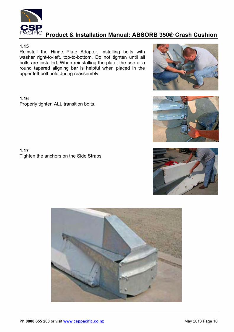
1) Uncap the 75mm fill hole located at the top of each unit, 2) Unpin the unit from adjacent units, One person with a pry bar can tip the unit on its side until it is partially drained and then rotate the unit upside down to be fully drained. Drainage can also be accomplished by using a water truck with vacuum or reversible pump capabilities. 8. Can the ABSORB 350® elements be moved when full? It is possible and extreme care must be taken, a full unit weighs 350kg. Each unit must be lifted mechanically and used with the appropriate machinery and safety equipment.

Product & Installation Manual: ABSORB 350® Crash Cushion
Ph 0800 655 200 or visit www.csppacific.co.nz May 2013 Page 18
ABSORB 350® Crash Cushion Maintenance Introduction As with any roadside safety device, the ABSORB 350® must be properly maintained to insure proper performance. Thoroughly review and fully understand the maintenance instructions and product limitations before performing any maintenance. Do not begin any maintenance operation without the proper plans and tools. For further guidance, refer to th ABSORB 350® Installation portion of this manual. If you require additional information or have questions about the ABSORB 350® Crash Cushion System please call CSP Pacific on 0800 655200 or email [email protected] Layout Conventions The picture of the ABSORB 350® system is labeled to show the descriptive terms that will be used throughout this manual. The descriptions are based standing at the nose end looking back. Note: Delineation is shown for illustrative purposes only. For applicable delineation refer to MoTSaM Part 2. .
Element Counting Convention The picture of the ABSORB 350® system above is labeled to show how the elements are numbered throughout this manual.
Right side
Product & Installation Manual: ABSORB 350® Crash Cushion
Ph 0800 655 200 or visit www.csppacific.co.nz May 2013 Page 19
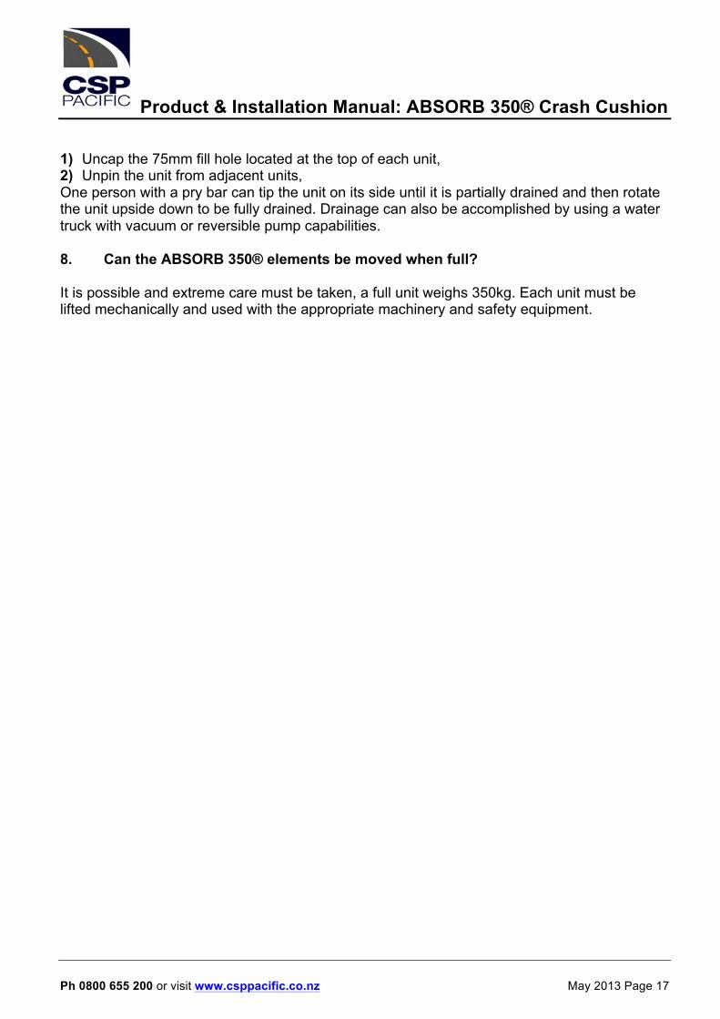
Inspection / Drive-By The frequency of Drive-By inspections is dependant on the traffic volume and the impact history of the system. Drive-By inspections are recommended at least monthly. 1) The inspector should be moving at a speed that is sufficiently slow enough to detect impact or environmental damage (debris). If any damage is observed, a Hands-On inspection is warranted. 2) Make sure that all of the elements are present and that there is no debris lodged between the elements. 3) If delineation has been applied to the nose cover, make sure that it is still properly applied and visible. 4) If the system appears to have been impacted in any way (scrapes, paint marks, etc.) a Hands-On inspection should be made. NOTE: It is important to keep a logbook of all Drive-By inspections for each installed system. Record the date of the inspection and observed condition of the system.
1) Look for tyre or paint marks on front and side transition. 2) Look for debris between elements (tyre, garbage, etc) under unit. 3) Look for transition damage. Although there may be no obvious damage, paint marks along the side would indicate an impact and the need for a hands on inspection.

Product & Installation Manual: ABSORB 350® Crash Cushion
Ph 0800 655 200 or visit www.csppacific.co.nz May 2013 Page 20
Inspection / Hands-on The frequency of Hands-On inspections is dependant on the traffic volume and the impact history of the system. Hands-On inspections are recommended at least yearly. 1) Check that all of the elements are straight. 2) Check in the spaces between the Energy Absorbing Elements (EAEs) to remove any debris that may have accumulated. 3) Check the water level in the elements. The water should be within 50mm of the top of the element. There should be no water in the element attached to the nose piece. 4) Check the condition of and the placement of all Energy Absorbing Elements. Replace any damaged Cartridges. Refer to the chart in Appendix “B” for proper placement. NOTE: It is important to keep a log book of all Hands-On inspections for each installed system. Record the date of inspection, the observed condition of the system and any replaced items. Post Impact Inspection – Repairs After an impact, the system must be thoroughly inspected to determine which parts can be reused and which parts will need to be replaced. The system must be repaired to its original condition to operate properly during the next impact. 1) If the system has sustained an impact, detach the damaged elements by removing the two side pins and properly discard. Replace the damaged element with the same type of element Type “A” or “B”. NOTE: Due to the possibility of reduced performance, any elements with bent side rods should be replaced. 2) Ensure that the system is re-installed in the proper configuration by referencing the system configuration chart in Appendix “B”. 3) Inspect for damage to the bolts that attach the transition. Remove and replace any damaged bolts. 4) Inspect the Nose Piece for damage. Repair or replace the Nose Piece if there is damage and apply the proper delineation. 5) Make sure that all of the pins are in place on both sides of the system.

Product & Installation Manual: ABSORB 350® Crash Cushion
Ph 0800 655 200 or visit www.csppacific.co.nz May 2013 Page 21
Appendix A Technical Drawings ABSORB 350® TL-3 - transitioned to concrete barrier - FX592 Page 22 ABSORB 350® TL-3 - connected to anchored concrete barrier Page 23 ABSORB 350® TL-3 - connected to unanchored concrete barrier Page 24 ABSORB 350® TL-3 - connected to anchored steel barrier Page 25 ABSORB 350® TL-2 - connected to anchored concrete barrier Page 26 ABSORB 350® TL-2 - connected to unanchored concrete barrier Page 27

Product & Installation Manual: ABSORB 350® Crash Cushion
Ph 0800 655 200 or visit www.csppacific.co.nz May 2013 Page 22
Appendix A Technical Drawings

Product & Installation Manual: ABSORB 350® Crash Cushion
Ph 0800 655 200 or visit www.csppacific.co.nz May 2013 Page 23

Product & Installation Manual: ABSORB 350® Crash Cushion
Ph 0800 655 200 or visit www.csppacific.co.nz May 2013 Page 24

Product & Installation Manual: ABSORB 350® Crash Cushion
Ph 0800 655 200 or visit www.csppacific.co.nz May 2013 Page 25

Product & Installation Manual: ABSORB 350® Crash Cushion
Ph 0800 655 200 or visit www.csppacific.co.nz May 2013 Page 26

Product & Installation Manual: ABSORB 350® Crash Cushion
Ph 0800 655 200 or visit www.csppacific.co.nz May 2013 Page 27

Product & Installation Manual: ABSORB 350® Crash Cushion
Ph 0800 655 200 or visit www.csppacific.co.nz May 2013 Page 28
Appendix B Letters of Approval Letter of Approval HAS-CC66 Pages 29 - 46 Letter of Approval HAS-CC66A Pages 47 - 51 NZTA Letter of Acceptance Pages 52 - 53
U.S. Departmentof Transportation
Federal HighwayAdministration
May 11, 2000400 Seventh St, S.W.Washington, D. C. 20590
Refer to: HSA-CC66
Mr. Edwin M. WoodVice PresidentBarrier Systems, Inc.1100 E. William Street, Suite 206Carson City, NV 89701
In your March 6 letter to Mr. Dwight A. Home, you requested the Federal HighwayAdministration’s (FHWA) acceptance for use on the National Highway System (NHS) of threedifferent designs of your ABSORB 350 crash cushion as a National Cooperative HighwayResearch Program (NCHRP) Report 350 device for use at either test level 2 (TL-2) or test level 3(TL-3). After reviewing the test reports and video coverage included with your letter, my staffrecommended that some additional tests be run based on the design of the TI-3 ABSORB 350and on its intended applications. On April 25, Mr. Owen Denman met with members of my staffand presented the results of the additional tests that you conducted.
The ABSORB 350 is a non-redirective, gating crash cushion primarily intended to shield theapproach ends of temporary concrete banier in general and Quick Change Median Barrier(QMB) segments in particular. As noted below, the ABSORB 350 may also be used to shieldpermanent concrete barrier at appropriate locations. The ABSORB 350 system consists of anosepiece assembly, followed by four, eight, or nine element assemblies, and atransition/attachment assembly. These assemblies can be seen in Enclosure 1. We note thatthere are two types of element assemblies and that these must be alternated when installed. Bothtypes are made from low density polyethylene and have internal structural components andconnection hardware fashioned from ASTM A-36 mild steel. These elements are 800-mm talland 610-mm wide. When empty, the element assemblies weigh 48 kg each. When filled withapproximately 300 liters of water, they weigh 315 kg. The first element in an array must be keptempty to ensure proper performance. All other elements must be filled with water. The eight-element and nine-element TL-3 designs are 8.2 meters long and 9.2 meters long, respectively; theproposed four-element TL-2 design is 4.4 meters long.
Test results were contained in two reports, both prepared by Safe Technologies, Inc., in RioVista, California. They are entitled “NCHRP Report 350 Crash Test Results For ABSORB 350Non-Redirective Crash Cushion (February 2000)” and a separate “ADDENDUM” to that reportdated April 2000. A total of five tests were reported on an eight-element array connected toQMB segments. These were NCHRP Report 350 tests 3-40 (AET02), 3-41 (AET01), 3-43

2
(AET03), 3-44 (AET04), and a “modified” test 3-44 (AET11) with the actual impact point closerto the rear of the installation to demonstrate the effect of a rear corner impact. We concur withyour statement that for the particular design of this device, NCHRP Report 350 test 3-42 may bewaived. Summary sheets for the five tests are included as Enclosure 2. You requested a TL-3acceptance of this design.
You also conducted two tests of a nine-element array. In the first of these tests (NCHRP Report350 3-41/Aet06), the ABSORB 350 was attached to a free-standing temporary concrete barrierconsisting of several 6-m long New Jersey shape segments. In the second test (NCHRP Report350 3-44 “modified”/AET07), it was attached to a “fixed” concrete barrier to replicate apermanent installation. Based on the results of these tests, summarized as Enclosure 3, yourequested TL-3 acceptance of a nine-element array when used to shield the ends of bothtemporary (minimum 6-m long segments) and permanent concrete barrier installations.
Finally, you conducted NCHRP Report 350 test 2-41 (AET05) into a four-element array at anominal impact speed of 70 km/h and requested acceptance of this unit at TL-2 based on that onetest. Enclosure 4 is a summary sheet of that test.
After reviewing the information you provided, my staff has concluded that the following designsmay be considered acceptable for use on the NHS at TL-3 when such use is requested by theappropriate transportation agency:
. the eight-element design when connected to QMB units when the leading top edgeof the first QMB unit is tapered as was done in the test
. the nine-element design when connected to permanent concrete barrier or totemporary concrete safety shaped barrier with individual segments having aminimum length of 6.1 m
In reviewing the single test you conducted on the four-element TL-2 design and comparing thisto tests run on other crash cushions at the TL-2 impact speed of 70 km/h, we do not haveadequate data to conclude that the shortened ABSORB 350 fully meets NCHRP Report 350evaluation criteria at TL-2. Previous testing of other TL-2 crash cushions has indicated thatNCBRP Report 350 test 2-40 may be critical from an occupant injury and vehicle stabilitystandpoint and that test 2-44 may be critical in regard to vehicle stability. Test results may alsodiffer depending on the type of barrier to which the four-element ABSORB 350 is connected,i.e., QMB, permanent concrete barrier, or non-anchored temporary concrete barrier. Should youwish to pursue acceptance of the ABSORB 350 at TL-2, please confer with Mr. Richard Powersat (202) 366.1320 to determine which test conditions will be appropriate.
Because the ABSORB 350 is a non-redirecting, gating cash cushion, care must be used in its

nose to near the mid-point of the array and penetration/override of the system is possible for highspeed, high angle impacts near the rear of the device. Your test report states that systems like theABSORB 350 (i.e., all gating, non-redirective crash cushions) “should be applied to hazards thatare not likely to be impacted at an angle on the side at any significant velocity.” We note alsothat proper antifreezing agents must be used as filler when the ABSORB 350 is used in areaswhere low temperatures can be anticipated. Other important usage considerations are noted inAppendix E (Test Article Deployment Instructions) of Safe Technologies’ crash test report. Allusers of this device should be made aware of the factors that contribute to its proper performance.
Since the ABSORB 350 is a proprietary crash cushion, its use on Federal-aid projects, exceptexempt, non-NHS projects, is subject to the conditions listed in Title 23, Code of FederalRegulations, Section 635.411. A copy of this regulation is enclosed for your ready reference.
5 Enclosures

SEE B991205.BOM FOR
MAT
ERIA
L LI
ST
Page
1 o
f 2

h /
ENCLOSURE 1(2 OF 6)-

- -
ENCLOSURE 1(3 OF 6)

2
;::-
\
ENCLOSURE l(4 OF 6)

ENCLOSURE: 1(5 OF 6)

1 ,
A

L ,
General InformationTest A g e n c y ................................................ S A F E TECHNOLOGIES I N C .Test Designation ........................................ NCHRP 350 3-40TestNo ...................................................... ABSORB 350/Test #AET02D a t e .......................................................... 2/4/00
Test ArticleType .......................................................... Barrier Systems, Inc.
ABSORB 350 Non-Redirective Crash CushionInstallation Length .............. . . . . ......................... 8.2m overall (8 ABSORB sections w/ nose)
Size and/or dimension and materialof key elements ........................................... Section length 1000mm, height 813mm,
width 610mm, mass 48kg empty/315kg FullTest Vehicle
Type ......................................................... Production ModelDesignation .............................................. 820CModel ....................................................... 1991, Ford Festiva
Mass (kg)Curb ..................................................... 807Testlner!M............................................ 834D”mnly(s) ............................................. 75Gross static.......................................... 909
Impact Conditionsspeed (km/h) ............................................ 89.3Angle(deg) ............................................... 0 at W4impact Severily (kJ) ................................... 3 1 7
E x i t ConditionsSpeed (km/h) .._._ .,. .,.... N/AA n g l e (deg ).....,,.,,,.,........ .._.. ,.............. NIA
Occupant risk ValuesImpact Velocity ( m / s )
x-direction . . . 1 0 . 2y-direction ,,,.......,,.................................. 4.3
Ridedown Accleration (g’s)x - d i r e c t i o n - 1 1y-direction __,..._,, .,,....,. .,......... - 3 . 2
THIV (m/s) 9.7PHD (g’s) .._....,,.,..,,................................... 11.3AS I........,....,.........,,.................................. 1.19
VOS ,,._..,,,_,,.__._, .._............. _.. ._............ FL-.?CDC .,,,,,.,,.,.,,,,,,..,..,..,,.,.,,.,..,,,,,,,..,,..,.. 12FLEN2
InteriorOCDI .._.._... ..__. .,.... . . AS0000000
Post-Impact Vehicular behavior (deg -gyro @ c.g)Max imum Roll Angle... ,._,,,,,. ,..,,..........,.. -413 (observed <10)Maximum Pitch Angle . . . . 49.2 (observed <10)Maximum Yaw Angle ..,.., .,. -198 (observed 260)
31 Figure 6. Summary of Results Test #AETO2

r
ABSORB 360 Assembly
oanerd lnfomlason EXR comtlonsTest Agency ................................................ SAFE TECHNOLOGIES, INC. SPeed(lunlh). .............................................. .7.5Test DesiQ”aoiw.......................................... NCHRP 350 341 Angle (deg). ................................................. 2 7Test,&, ...................................................... ASSORBIO/TastOAETO1 Occupant rlSk valuerDate .......................................................... 2115100 Impaawcc~ (my
Test Article X-dltilMl.............................................. 9.7Type .......................................................... Sarriw Sybms, I11c. y-dire&m.. ............................................ 0.3
ABSORB 300 Nm!-Rglirecow Crash Cushion Rldgloun Aosekratim (a’s,,nsta,latlon Lenglil.............................................. 5.2m cwall(0 ABSORB se%cns w / we) x-dktbn.. ............................................ 11.8
.siie andlor d,mens,Ml and n!atelial ydi~“. ............................................. 4.0of key e leme* ........................................... secocn length 1ooormn. height s13mm. THI”(mls) ................................................. 8,7
width 01 Omm. mass 45kg empty ,315kg Full Pm (Q’S). .................................................. 13.0Test “ehkls AS,. ......................................................... ,o.oo
Type ......................................................... mduc5on MM@Designation.. .............................................. 2M)OPMcd~ ....................................................... IQOQ, Chevmlel SilWadO2500
3/d To” Pickup “ehlck OamaQe
MssS w EXWINC!Jk ................................................ .: ... 1001 VTX.. ................................................... Fc-4Test tnerual... ......................................... 1075 CDC.. ....................... . ........................... 12FDEW2D”nmly(s). ............................................ nia l”tediCIomss static .......................................... ,976 OCDI.. .. . . . . . . . . . . . . . . . . . . . . . . . . . . . . . . . . . . . . . . . . . . . . . . . . AS0000000
impact Co”dBons Post-Impact “ehl”,la~ behavior ,deg .gym @ e.g.)speed (kmh). ............................................ 00.2 Wnl”nl Rdl A”!#. ................................... 0.5 (obswvm 40,Angle (deg, ............................................... 0 Maximum Pitch Angle.. ............ .................... -27.4 (owna c 10)mpad SevRlLy (k.J) .................................... 750 Madm”mVawh$e .................................... -31.2 (obswved 30,
Figure 1. Summary of Results Test #AETOl

LT
”/
:;
:;
i:
::
:;
::
j:
::
:;
:
i :
GemB
: :
: i
: :
: :
: :
1 :
: f
: :
: :
i 1
: i
j i
: i
: :
: :
: :
; :
j i
j .s2df
SC2
; :
j I
: :
: :
: i
i :
f i
EN
CL
OSU
RE
2 (3 OF 5)-


General information EXH Condl*lonsTest Agency ........................................... SAFETECHNOLOGIES, I N C . Speed (hwil, ......................................... .7.9
Test Desipnation ...................................... NCHRP 350 3-41 An** (@a) .......................................... ..2 0
TeStNo .................................................. AssOW3501Test#AErOB occupant Ibk “ltl”BI
oate ...................................................... 311100 krQact”ebcily (rrk,
Test Article x - d i r e c t i o n ....................................... 1 0 . 1
Type ............... . ...................................... Barrier System. kc. y4irectian ....................................... - 0 . 3
ABSORB 350 Non-Redirective Crash C”shio” l?Mdcw n Acceleration (g’s,
lnstallatlo” Length.. ..................................... 9.2ma”erall(g ASSORB sectlo” w I nose, x-direction ....................................... -14.3
Size andlor dirmnsbn and material y-direction ....................................... 5 . 4
Of key elements ...................................... section length 1owmm, height 813mllJ THN (nvSj.. .......................................... IO.1
width 61 man n!aSb 4&g ernpiy I 315!%g Full PHo(g’*j.. ........................................... 1 4 . 4
TestVehicle AS, .................................................... 0.95
Type.................................................... Frod”tib” Madd
OEsignation ........................................... 2OOOF
M o d e l ................................................... ILWS, GW S i e r r a 314 T o n p i c k u p“ehlcle oamage
Mars (kg) E x t e r i o r
CWb ................................................ 1932 “OS ................................................ FC3
Test inertial ....................................... 1985 cm ............................................... . lPFOEw,
o”mmf(sj ......................................... “la blterior
Gross s ta t ic ...................................... 1985 OCOI ............................................... ASOOOOrJOO
Impact Conditiom Port-lmpact”ehk”lar behavior ,lhg . gyro @ E.g.)
Speed (krtvh, ........................................ 97 Maxirmnl RollA”*ki .............................. 12.8 (observed 410)Angk (degj.. ............................ ........... 0 M a x i m u m Wh Ang le ............................. -12.9 (obeerved cs)
Impact severity NJ, .............................. ..72 0 MaximumYaw Angle ............................. -15.7 (observed 20)
Figure 26. Summary of Results Test #MT06


ABSORB 350 Four Element System (70 km/h)
sp%d(knyh) 0.7Angle (d&l ,.......,....,................. 28
occupant *ii “BlUeaImpad “e!ccity (mk,
X-dirsctiM ,...... 7.3y-&&on I
Rme4.n Acco(h ,&I’S,X4 idMI ,............................................. -7.7y-dirEctiml......................,.................,..... -3.1
THl” (rdS) 7.4PHD ($8) 7.8AS, ,,. ,,. 0.64
“ehlcle chnlqle-
“OS Fc-4ccc . 12FCENZ
Intmixiamm ._..., .., ,.. As0000000
Post-lmpad “ahlcvlar brhwlor ,deQ _ gym BC.0.)Maxinwm Rdl Angle 8.7 @bsed 6,MaSmum Pitch Angle ..,._,..,..... ,,,,.,..,..,........ -0.5 (observed 40)Mt im”mYawmgle .,,,,,,,.,.. .,,.,..............,. -50.9 (chewd a)
P Figure 21. Summary of Results Test #AETOS

Sec. 635.411 Material or product selection.
(a) Federal funds shall not participate, directly or indirectly, in payment for any premium or royaltyon any patented or proprietary material, specification, or process specifically set forth in the plansand specifications for a project, unless:
(1) Such patented or proprietary item is purchased or obtained through competitive bidding withequallysuitable unpatented items; or
(2) The State highway agency certifies either that such patented or proprietary item is essential forsynchronization with existing highway facilities, or that no equally suitable alternate exists; or
(3) Such patented or proprietary item is used for research or for a distinctive type of construction onrelatively short sections of road for experimental purposes.
(b) When there is available for purchase more than one nonpatented, nonproprietary material,semifinished or finished article or product that will fulfill the requirements for an item of work of aproject and these available materials or products are judged to be of satisfactory quality and equallyacceptable on the basis o f engineering analysis and the anticipated prices for the related item(s) ofwork are estimated to be approximately the same, the PS&E for the project shall either contain orinclude by reference the specifications for each such material or product that is consideredacceptable for incorporation in the work. If the State highway agency wishes to substitute someother acceptable material or product for the material or product designated by the successful bidderor bid as the lowest alternate, and such substitution results in an increase in costs, there will not beFederal-aid participation in any increase in costs.
(c) A State highway agency may require a specific material or product when there are otheracceptable materials a n d products, when such specific choice is approved by the DivisionAdministrator as being in the public interest. When the Division Administrator’s approval is notobtained, the item will be nonparticipating unless bidding procedures are used that establish the unitprice of each acceptable alternative. In this case Federal-aid participation will be based on thelowest price so established.
(d) Appendix A sets forth the FHWA requirements regarding (1) the specification of alternativetypes of culvert pipes, and (2) the number and types of such alternatives which must be set forth inthespecitications for various types of drainage installations.
(e) Reference in specifications and on plans to single trade name materials will not be approved on

U.S. Departmentof T ransportat ion
Federal HighwayAdministrat ion
400 Seventh St., S W.Washington D.C. 20590
Refer to: HSA-CC66A
Mr. Edwin M. WoodVice PresidentBarrier Systems, Inc.1100 E. William Street, Suite 206Carson City, NV 8970 1
Dear Mr. Wood:
My May 11 letter to you accepted the eight- and nine-clement ABSORB 350 crash cushion as aNational Cooperative Highway Research Program (NCHRP) Report 350 Test Level 3 (TL-3)attenuator for use with your Quickchange Median Barrier (QMB) and with permanent andtemporary concrete barrier, respectively. Use with temporary barrier was limited to individualbarrier segments of 6.1 m or longer. I also indicated that additional tests would be neededbefore the FHWA could consider a reduced-length array to be an acceptable TL-2 design.
Your June 1 letter referenced the May 3 1 meeting during which Mr. Owen Denman providedmembers of my staff with a report on the additional tests that you conducted. In that letter, yourequested acceptance of a modified TL-2 ABSORB 350 design for use on the NationalHighway System (NHS) as well as the acceptance of a modified TL-3 design for use withpermanent concrete barrier and temporary concrete barrier with segments as short as 3 m.
The modified TL-2 design consists of the nosepiece assembly, five ABSORB 350 elements,and a special Attachment/Transition Assembly (for attachment to standard concrete barrier).Enclosure 1 shows this assembly. When attached to QMB barrier, the first QMB unit must bemodified as noted in the May 11 acceptance letter. Summary sheets of the two tests that wererun on the final TL-2 design are shown in Enclosure 2.
Based on staff review of the test results, as reported in Safe Technologies, Inc.., May 2000report entitled “NCHRP Report 350 Crash Test Results, ABSORB 350 Non-Redirective CrashCushion, ADDENDUM II, Test Level - 2”, the ABSORB 350 TL-2 design, as described above,is acceptable for use on the NHS when such use is requested by a transportation agency.Additionally, the nine-element TL-3 design may be used with temporary concrete barriersegments as short as 3 meters when the attachment/transition assembly shown in Enclosure 1 isused between the crash cushion and the concrete barrier. Based on discussions between my

2
staff and Mr. Denman, you will also require the use of this assembly when connecting theABSORB 350 to longer concrete segments and to permanent concrete barrier, As noted in boththe test report and your letter, the ABSORB 350 performs well for a non-redirecting attenuator,but by design, it does not redirect vehicles striking the side of the unit. Under some impactconditions, vehicles can penetrate or vault the ABSORB 350 and intrude into the “shielded”area. It is of utmost importance that this device be used primarily in locations where such hitsare expected to be rare and unlikely to compromise motorist or worker safety if they do occur.I assume that you will provide potential users with sufficient information on design and layoutrequirements to minimize the risks involved when this non-redirective attenuator is selected toshield the end of concrete barrier.
Sincerely yours,
Frederick G. Wright, Jr.Program Manager, Safety
2 Enclosures

afe Technologies, Inc. Appendix B (Continued)
.-
--
?
Enclosure 1

Nose Attachment
Portable Concrete Barrier -
Test Level 2 ABSORB 360 AssemblyGeneral Information
Test Agency... ` ., . . _,, . _.. ,.. . . . . . . SAFE TECHNOLOGIES, INC.Test Designation ., . . . . ,.. .,. . . . . . . . . ,. . . . NCHRP 360 2-44 (modifiedTest No... .,_ . . . .,. ,., ,._,....t __. ..I. . . ,.. . . . ABSORB 350 I Test #AET15Data., . . . . . . . . . . . . . . . 5/18/00
Test ArticleType.. _. . . . . ., . . . . . . . Barrier Systems, Inc.
ABSORB 350 Non-Redirective Crash Cushioninstallation Length . . . . . . ..*..................................... 5.2 m overall (5 ABSORB sections w I nose)
Size and/or dimension and material
of key elements... ,.. . . . ._. ., . . ,.. . . .,, . . . Section length 1000mm, height 813mm,width 610mm, mass 48kg empty/ 315kg Full
Test VehicleType.. .., ,.. .., ,,. ,.. ,.. . . . . . . . . . . . . . . . . . . . Production ModelDesignation... .,. ,_. .,. . . . .._ ., .,. . .., .Model... ,,, .__...,.. . .,.......... . . . . . . . . . . . . 1975, Chevrolet 3/4 TM Pickup
Mass (kg)Curb... _,. ,.. ,.. . ._. ,,, . . . . . .,. .I... 2099Test Inertial.. _.. . ,,. ___ ., .,. ., 1976Dummy(s).. . . . . . . . n/aGross Static.. . . ..I ,. .., . .., 1976
impact ConditionsSpeed (km/h)... .,. . . . . . . . .._..._..._................... 7 1 . 2Angle (de&!)... _. _.. _.. ,. ,,, ,.. ,,, .,. .., ,, .., ,., ,.. ., 2 0Impact Severity (kJ) . .,. .., ,., ..___ ,.. .., .., 3 8 6
Speed (km/h) .............................................. /34/6Angle (deg). ................................................. Behind Article
Occupant risk ValuesImpact Velocity (m/s)
x-direction.............................................. 5.6y d i i i o n .............................................. -0.1
Ridedown Acceleration (g’s)x-direction .............................................. 7 . 5y-direction.. ............................................ 8.4
THIV (m/s) ................................................. 5.6PHD (g’s) ................................................... 17.9ASI .......................................................... .0.52
Vehicle DamageExterior
VDS... . . . . . . ., . . . . . . . . . . . . . . . . . ., FR-2
CDC. . . . . 1,s. ..,,I. .,, ,..,,.,..,1, . . . I.,.,, ..I . . . . . . . . . . . WREE2
InteriorOCDl . . . . . . . . . . . . . . . . . . ,.. . . . . . AS0000000
Post-Impact Vehicular behavior (deg - gyro @ c.g.)Maximum Rdl Angle... . . . . . . . . . .,. . . . . . . . . . . . 56.3Maximum Pitch Angle... . . . . . . . . .., . . . . . . . .., . . 10.1Maximum Yaw Angle... . . . . . . . . . . . . . . . . . .., -40
Figure 1. Summary of Results Test #AET15


Interim Acceptance for ABSORB 350® temporary crash cushion system May 2013
Page 1
May 2013
Interim Acceptance for Safety Barrier Product Product: ABSORB 350® Temporary Crash Cushion Safety Barrier - Temporary Expiry Date: 30 June 2017
The ABSORB 350® temporary crash cushion has FHWA approval and has been used in New Zealand as an end terminal for temporary traffic management barrier systems for over 10 years. To date it has not been listed in the NZTA M23 specification. This notice is intended as an interim authority to use the ABSORB 350® temporary crash cushion as a TL2 or TL3 temporary barrier end treatment pending its listing in M23 Appendix C (Temporary Systems). Product Identification
ABSORB 350® Temporary Crash Cushion The ABSORB 350® temporary crash cushion was successfully tested as an end terminal system under the NCHRP 350 standard for both Test Level 2 (70 km/h) and Test Level 3 (100 km/h). The FHWA issued letters of acceptance CC-66 (May 2000) and CC-66A (June 2000) for the use of the ABSORB 350®. Additionally, the FHWA issued a letter of acceptance CC-66B (December 2003) approving the use of the ABSORB 350® as an end treatment for temporary steel barrier. The FHWA noted some concerns should the ABSORB 350® temporary crash cushion be struck laterally near to the transition to the barrier section the temporary crash cushion was protecting. Under some impact conditions vehicles can penetrate or vault the ABSORB 350® and intrude a significant distance (over 30m) into the shielded area. The FHWA letters of acceptance emphasise that the supplier will give sufficient information on design and layout requirements to minimise the risks involved when this, non-redirective, temporary crash cushion is selected to shield the end of a concrete or steel barrier. This information must be included in any product installation manual.

Interim Acceptance for ABSORB 350® temporary crash cushion system May 2013
Page 2
Conditions of Use
In situations where the ABSORB 350® temporary crash cushion is used to shield temporary traffic management barriers, the following must be considered:
• There must be sufficient free space for recovery behind the temporary crash cushion should the vehicle strike the terminal laterally and pass through.
• The temporary crash cushion is only to be installed where it is likely to be struck head on. • The temporary crash cushion must not be installed on curves or wide roads where steep angles
of impact are more likely. • When installed on concrete barrier, the temporary crash cushion must only be attached using
the approved proprietary transition attachment. • When installed on steel barrier, the temporary crash cushion must only be attached using the
approved proprietary transition attachment for the steel barrier system and the final lengths of steel barrier must be pinned or fixed to the road surface in accordance with the manufacturers specifications.
• The temporary crash cushion must contain the correct number of segments required for the test level appropriate for the situation.
• The supplier of the hardware remains responsible under the Health and Safety in Employment legislation for ensuring that customers have the necessary knowledge and skills to correctly use the product.
A copy of this Interim Acceptance Notice must be appended to the Installation Manual. Expiry of Acceptance
This acceptance expires on 30 June 2017 and replaces any previous acceptance. New installations of the ABSORB 350® temporary crash cushion system must not be deployed on the state highway network after the expiry date of acceptance unless a further period of acceptance is granted or the product has been formally included in the NZ Transport Agency M23 Specification for Road Safety Barrier Systems, in which case the M23 specification would replace this interim acceptance. Should the NZ Transport Agency discover that the qualification testing was flawed, that in-service performance reveals unacceptable safety problems, or that the system being marketed differs significantly from that which was crash tested, it reserves the right, at any time, to modify or revoke its acceptance of the ABSORB 350® temporary crash cushion system. Authorised by the National Manager Traffic & Safety