ABSeiL AnchORS - · PDF fileABSeiL AnchORS 021. ... with stainless steel bolts, washers and...
17
REVISION NO: 001 PRODUCT DATA SHEET REPORT NO: 021 PRODUCT CODE: AB300 ABSEIL ANCHORS 021
Transcript of ABSeiL AnchORS - · PDF fileABSeiL AnchORS 021. ... with stainless steel bolts, washers and...

ReviSiOn nO: 001PRODUcT DATA SheeT RePORT nO: 021
PRODUcT cODe: AB300
ABSeiL AnchORS
021

For any technical queries please call our advice line on 0845 241 9102
PROdUcT dEScRIPTION:Abseil anchors are designed to be fixed to a structural substrate such as structural steel or concrete to provide suitable rope access connection points. It is essential when designing rope access to ensure at least 2 different connection points are available to connect to at any one time. There are 2 types of abseil anchors available – abseil brackets and abseil eyebolts. Brackets are supplied in galvanised steel with stainless steel components. Neoprene washers ensure no galvanic reaction can take place. Abseil eyebolts are supplied in stainless steel . Brackets and eyebolts are secured to concrete with resin anchors and to steelwork with stainless steel bolts, washers and vibration proof nuts. When fixing to metal deck or timber deck it may be necessary to provide a backing plate to ensure compliance.
The brackets are designed for 1 user at any one time and 2 users in the event of emergency access requirements. Brackets need to be positioned so any rope connections do not exceed a 120 degree angle when in use – an angle of 90 degrees is recommended. This will be determined by the design layout and position of the anchors. Involving our specialist design teams as early as possible will ensure the most cost effective system is used without compromising any safety or access requirements. Our designers will consider the welfare and safety of both rope access and non-rope access personal during the construction and future use.
AviATOR ABSeiL AnchORS
Bracket
General arrangement
Absolute maximum angle
Recommended angle(the smaller the better)
Angle to be avoided
1 0.7kN
1.0kN 2.0kN
900
1kN
1kN 1kN
0.7kN
1.0kN 2.0kN
2
<1200 >1200
4
3 3
3 ✗
1
Eyebolt
Key 1 Anchor2 y angle
3 Anchor line4 Load
021

For any technical queries please call our advice line on 0845 241 9102
Brackets can be supplied in varying heights from 150mm up to 550mm to accommodate different roof constructions. The brackets are manufactured with a strengthening gusset to ensure compliance with 15kN design load requirements. Eyebolts are supplied in 150mm or 100mm lengths for concrete and block/brick fixing. Shorter eyebolts of 50mm are used in structural steel. For timber of sufficient strength the 150mm eyebolt can be used with vibration resistant locking nuts and large washers either side. A minimum thickness of 125 mm treated timber is required. Both abseil anchors and eyebolts can be
installed on the horizontal or vertical substrates of a building. Careful consideration must be taken when designing the abseil positions to ensure abseil ropes will not foul with any roof plant or roof penetrations. If ropes are required to lie over any parapet walls or edge protection such as balustrading it will be necessary to ensure that the parapet has been re-enforced. The use of a abseil rope spreader plate can reduce the point loading considerably.
The main contractor is responsible for calculations regarding building loading capabilities and is responsible for the re-enforcement of the parapet.
AviATOR ABSeiL AnchORS
Bracket heights
Rope over parapet wallConcrete Block / Brickwork eyebolts
Steel fix Timber fix
Socket
150mm
150mm
50mm
100mm
100mm
250mm
350mm
ULS15kN
450mm
550mm
150mm
021

For any technical queries please call our advice line on 0845 241 9102
021
AviATOR ABSeiL AnchORS
Yield 275 N/mm² C 0.15 – 0.26; Si < 0.35; Mn < 1.5; P < 0.035;
S < 0.040; Mo 0.4 – 0.6.
Young’s Modulus of Elasticity 200 x 103 MPa at 20 °C
Density 7.87 g/cm3 at 20 °C
Coefficient of Thermal Expansion Low-Carbon/HSLAS: 12.4 μm/m/°C in 20 °C to 100 °C range
I-F Steel: 12.9 μm/m/°C in 20 °C to 100 °C range
Thermal Conductivity Low-Carbon/HSLAS: 89 W/m°C at 20°C I-F Steel: 93 W/m°C
at 20°C
Specific Heat 481 J/kg/°C in 50 °C to 100 °C range
Electrical Resistivity 0.142 μΩ•m at 20 °C
MATERIAL SPEcIFIcATION:
brackets - galvanised steel
component partsStainless Steel - Grade 304 (UNS S30400)Fe, <0.08% C, 17.5-20% Cr, 8-11% Ni, <2% Mn, <1% Si, <0.045% P, <0.03% Stainless Steel
Rain capPolyvinyl Chloride-PVC. Tensile Strength 2.60 N/mm², Notched Impact Strength 2.0 - 45 Kj/m², Thermal Coefficient of expansion 80 x 10-6 , Max Cont Use Temp 60 C, Density 1.38 g/cm
Galvanised steel
Stainless steel

For any technical queries please call our advice line on 0845 241 9102
OPERATING ANd dESIGN STANdARdS:Eurocodes are designated by EN
British standards are designated by BS
• Steel – EN10 113 and EN 10 025• BS 7985: 2013 Code of Practice for
Rope Access Methods• The lifting operations and lifting equipment
regulations 1998• LOLER REG. 5(1) (a and b) for design• LOLER REG. 7(a, d and e) for marking• LOLER REG. 9 (1, 2 , 3 a and b) for examination• ISO 9001:2008, ISO14001:2004, BS OHSAS
18001:2007• Management of health and safety at work
regulations 1999 (MHSWR) ref.2• Work at height regulations 2005 (Ref 7)• Work at height (amended) regulations 2007
(Ref. 8) WAHR
• Provision and use of work equipment regulations 1999 PUWER 98 (Ref.5)
• The work at height safety association WAHSA- guidance on inspecting eyebolts for personal fall protection purposes
✔
BS ENISO
Standards
Typical connection loads (550mm maximum height of eyebolt connection from base)
9948ISO 9001:2008
9948ISO 14001:2004
9948BS OHSAS 18001:2007
AviATOR ABSeiL AnchORS
Ultimate factored load on bracket base
Bracket moment
Tension
horizontal shear
15.0kN 7.8kN
9.89kN/m 16.95kN
Note: For guidelines only to be checked by Chief Engineer.
021
The company operates to the following standards
For any technical queries please call our advice line on 0845 241 9102
021
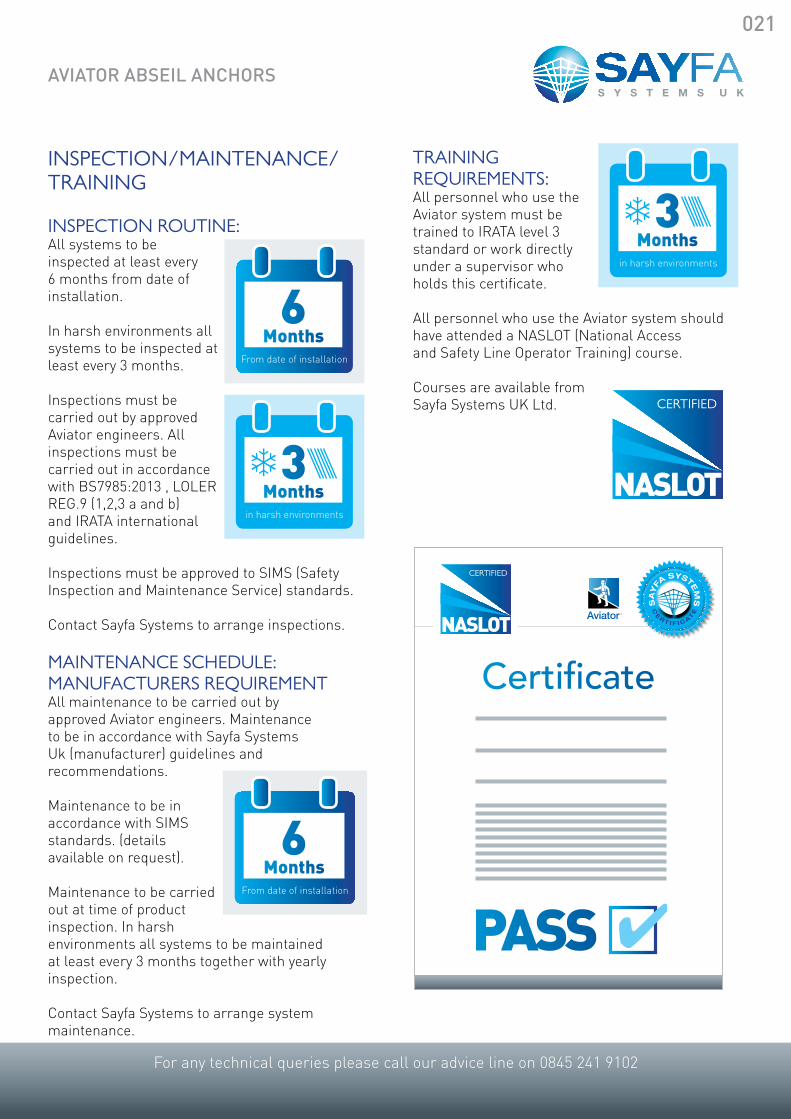
TRAINING REQUIREMENTS:All personnel who use the Aviator system must be trained to IRATA level 3 standard or work directly under a supervisor who holds this certificate.
All personnel who use the Aviator system should have attended a NASLOT (National Access and Safety Line Operator Training) course.
Courses are available from Sayfa Systems UK Ltd.
INSPEcTION/MAINTENANcE/TRAINING
INSPEcTION ROUTINE:All systems to be inspected at least every 6 months from date of installation.
In harsh environments all systems to be inspected at least every 3 months.
Inspections must be carried out by approved Aviator engineers. All inspections must be carried out in accordance with BS7985:2013 , LOLER REG.9 (1,2,3 a and b) and IRATA international guidelines.
Inspections must be approved to SIMS (Safety Inspection and Maintenance Service) standards.
Contact Sayfa Systems to arrange inspections.
MAINTENANcE SchEdULE: MANUFAcTURERS REQUIREMENTAll maintenance to be carried out by approved Aviator engineers. Maintenance to be in accordance with Sayfa Systems Uk (manufacturer) guidelines and recommendations.
Maintenance to be in accordance with SIMS standards. (details available on request).
Maintenance to be carried out at time of product inspection. In harsh environments all systems to be maintained at least every 3 months together with yearly inspection.
Contact Sayfa Systems to arrange system maintenance.
6 Months
From date of installation
NASLOT
cERTIFIEd
3Months
in harsh environments
d
Sa
yfa
SyStem
S
Ce
R t I f I C a
te
NASLOT
cERTIFIEd
Certificate
PASS ✔
3Months
in harsh environments
d
6 Months
From date of installation
AviATOR ABSeiL AnchORS

For any technical queries please call our advice line on 0845 241 9102
cOMPONENT PART dETAILS:Abseil brackets Ab300 bIM No: SpecEquip_RfSftySymAbslbkt_SayfaSystems_Ab300_M3_G2
Resin fix Abseil eyebolts EbRF370 bIM No: SpecEquip_RfSftySymAbsEye bltcon_SayfaSystems_EbRF370_M3_G2
Steelwork abseil eyebolts EbSF365 bIM No: SpecEquip_RfSftySymAbsEye bltStl_SayfaSystems_EbRF365_M3_G2
Timber abseil eyebolt EbRF390 bIM No: SpecEquip_RfSftySymAbsEye bltTimb_SayfaSystems_EbRF390_M3_G2
AviATOR ABSeiL AnchORS
021

For any technical queries please call our advice line on 0845 241 9102
021
FIxING dETAILS: Abseil bracket fixed to concrete slab
AviATOR ABSeiL AnchORS
GALVANISED STEEL BRACKET
PVC RAIN CAP
M16 STAINLESS STEEL EYE BOLT
M10 RESIN ANCHORSET 125mm INCONCRETE
150m
m-5
50m
m
NEO PRENE WASHER
SYSTEM LABEL
STAINLESS STEEL WASHER
INSULATION TO CLIENTSPECIFICATION
SEDUM LAYERTO CLIENT SPECIFICATION
GROWING LAYERTO CLIENT SPECIFICATION
DRAINAGE LAYERTO CLIENT SPECIFICATION
PITCH POCKET SEALING DETAIL(RECOMMENDED)BY ROOFING CONTRACTOR
POST TO CLEARSEDUM BY MINIMUM 100mm
METAL DECKTO CLIENT SPECIFICATION
MINIMUM 150mm THICKCAST CONCRETE SLAB
BRACKET GUSSET
Client:
Contract:
Project Title:
Line to be located as indicated on theroof plan.
Line primarily used to gain access toexposed roof edges.
Incorporates Aviator™ units and allSayfa Systemscomponents required.
Fixing details for Aviator™ units asindicated within layout.
System to be used in conjunction with2m restraining lanyard unless statedotherwise.
Enables two users simultaneously atany one time.
System Details
SAYFA SYSTEMS
FIXING DETAIL
AVIATOR™ABSEIL ANCHORSYSTEMFIXED TO CASTCONCRETE SLAB
Revision:
Drawn By: MW
Scale:
Date:
Checked By:
Job No:
DWG No:
Jubilee House
ShepshedLeicestershireLE12 9NHT: 0845 241 9102F:0845 130 4520www.sayfasystems.com
Unit 3, Gelders Hall Road
Status:
UNDER THE CDM REGULATIONS 200, IF ANY ALTERATIONS ARE MADE TO THIS DRAWING THEN THE PERSON UNDERTAKING THESE CHANGES ASSUME THE ROLE OF THE DESIGNER, THEREFORE TAKING FULL CDM RESPONSIBILITY.
A = Access point
Drawing Symbols
THIS DRAWING IS PROTECTED BY COPYRIGHT AND THE INFORMATION HEREIN IS CONFIDENTIAL. THE DRAWING MAY NOT BE COPIED AND THE INFORMATION HEREIN MAY NOT BE USED OR DISCLOSED EXCEPT WITH THE WRITTEN PERMISSION OF SAYFA SYSTEMS ©
DRAWING REVISIONSREV DATE COMMENT
THIS DRAWING WAS CREATED INCONJUNCTION WITH ____________
DRAWING NO. ______________
TYPICAL FIXING DETAILS
22/12/2014
As Dimensioned
For DesignN/A
N/A
001
DJ

For any technical queries please call our advice line on 0845 241 9102
GALVANISED STEEL BRACKET
PVC RAIN CAP
M16 STAINLESS STEEL EYE BOLT
M10 RESIN ANCHORSET 125mm INCONCRETE PRE CAST SLAB
150m
m-5
50m
m
NEO PRENE WASHERSTAINLESS STEEL WASHER
SYSTEM LABEL
INSULATION TO CLIENTSPECIFICATION
SEDUM LAYERTO CLIENT SPECIFICATION
GROWING LAYERTO CLIENT SPECIFICATION
DRAINAGE LAYERTO CLIENT SPECIFICATION
PITCH POCKET SEALING DETAIL(RECOMMENDED)BY ROOFING CONTRACTOR
POST TO CLEARSEDUM BY MINIMUM 100mm
TOGGLE FIXINGIF FIXING HOLEBREAKS THROUGHHOLLOWCORE
PRE CAST HOLLOWCORESLAB TO CLIENTSSPECIFICATION
BRACKET GUSSET
Client:
Contract:
Project Title:
Line to be located as indicated on theroof plan.
Line primarily used to gain access toexposed roof edges.
Incorporates Aviator™ units and allSayfa Systemscomponents required.
Fixing details for Aviator™ units asindicated within layout.
System to be used in conjunction with2m restraining lanyard unless statedotherwise.
Enables two users simultaneously atany one time.
System Details
SAYFA SYSTEMS
FIXING DETAIL
AVIATOR™ABSEIL ANCHORFIXED TO HOLLOWCORECONCRETE SLAB
Revision:
Drawn By: MW
Scale:
Date:
Checked By:
Job No:
DWG No:
Jubilee House
ShepshedLeicestershireLE12 9NHT: 0845 241 9102F:0845 130 4520www.sayfasystems.com
Unit 3, Gelders Hall Road
Status:
S:\Design\Mark's Temp CAD\SAYFA CAD Templates\SAYFA CAD TEMPLATE FILES\Sayfa_Logo_New.jpg
UNDER THE CDM REGULATIONS 200, IF ANY ALTERATIONS ARE MADE TO THIS DRAWING THEN THE PERSON UNDERTAKING THESE CHANGES ASSUME THE ROLE OF THE DESIGNER, THEREFORE TAKING FULL CDM RESPONSIBILITY.
A = Access point
Drawing Symbols
THIS DRAWING IS PROTECTED BY COPYRIGHT AND THE INFORMATION HEREIN IS CONFIDENTIAL. THE DRAWING MAY NOT BE COPIED AND THE INFORMATION HEREIN MAY NOT BE USED OR DISCLOSED EXCEPT WITH THE WRITTEN PERMISSION OF SAYFA SYSTEMS ©
DRAWING REVISIONSREV DATE COMMENT
THIS DRAWING WAS CREATED INCONJUNCTION WITH ____________
DRAWING NO. ______________
TYPICAL FIXING DETAILS
22/12/2014
As Dimensioned
For DesignN/A
N/A
001
DJ
AviATOR ABSeiL AnchORS
FIxING dETAILS: Abseil bracket fixed to concrete hollow core slab
021

For any technical queries please call our advice line on 0845 241 9102
021
GALVANISED STEEL BRACKET
PVC RAIN CAP
M16 STAINLESS STEEL EYE BOLT
TOGGLE FIXING WITH M8 THREADED BAR
18MM TIMBER OR GREATER TOCLIENT SPECIFICATION
150m
m-5
50m
m
NEO PRENE WASHER
SYSTEM LABEL
STAINLESS STEEL WASHER
INSULATION TO CLIENTSPECIFICATION
SEDUM LAYERTO CLIENT SPECIFICATION
GROWING LAYERTO CLIENT SPECIFICATION
DRAINAGE LAYERTO CLIENT SPECIFICATION
PITCH POCKET SEALING DETAIL(RECOMMENDED)BY ROOFING CONTRACTOR
POST TO CLEARSEDUM BY MINIMUM 100mm
BRACKET GUSSET
18mm TIMBER BACKING PLATE BYROOFING CONTRACTOR 500mm x 500mm
Client:
Contract:
Project Title:
Line to be located as indicated on theroof plan.
Line primarily used to gain access toexposed roof edges.
Incorporates Aviator™ units and allSayfa Systemscomponents required.
Fixing details for Aviator™ units asindicated within layout.
System to be used in conjunction with2m restraining lanyard unless statedotherwise.
Enables two users simultaneously atany one time.
System Details
SAYFA SYSTEMS
FIXING DETAIL
AVIATOR™ABSEIL ANCHORFIXED TOTIMBER DECK
Revision:
Drawn By: MW
Scale:
Date:
Checked By:
Job No:
DWG No:
Jubilee House
ShepshedLeicestershireLE12 9NHT: 0845 241 9102F:0845 130 4520www.sayfasystems.com
Unit 3, Gelders Hall Road
Status:
UNDER THE CDM REGULATIONS 200, IF ANY ALTERATIONS ARE MADE TO THIS DRAWING THEN THE PERSON UNDERTAKING THESE CHANGES ASSUME THE ROLE OF THE DESIGNER, THEREFORE TAKING FULL CDM RESPONSIBILITY.
A = Access point
Drawing Symbols
THIS DRAWING IS PROTECTED BY COPYRIGHT AND THE INFORMATION HEREIN IS CONFIDENTIAL. THE DRAWING MAY NOT BE COPIED AND THE INFORMATION HEREIN MAY NOT BE USED OR DISCLOSED EXCEPT WITH THE WRITTEN PERMISSION OF SAYFA SYSTEMS ©
DRAWING REVISIONSREV DATE COMMENT
THIS DRAWING WAS CREATED INCONJUNCTION WITH ____________
DRAWING NO. ______________
TYPICAL FIXING DETAILS
22/12/2014
As Dimensioned
For DesignN/A
N/A
001
DJ
AviATOR ABSeiL AnchORS
FIxING dETAILS: Abseil bracket fixed to plywood deck

For any technical queries please call our advice line on 0845 241 9102
GALVANISED STEEL BRACKET
PVC RAIN CAP
M16 STAINLESS STEEL EYE BOLT
TOGGLE FIXINGWITH M8 THREADED BAR
SEALING BASETO CLIENT SPECIFICATION
150m
m-5
50m
m
NEO PRENE WASHER
SYSTEM LABEL
STAINLESS STEEL WASHER
INSULATION TO CLIENTSPECIFICATION
SEDUM LAYERTO CLIENT SPECIFICATION
GROWING LAYERTO CLIENT SPECIFICATION
DRAINAGE LAYERTO CLIENT SPECIFICATION
PITCH POCKET SEALING DETAIL(RECOMMENDED)BY ROOFING CONTRACTOR
POST TO CLEARSEDUM BY MINIMUM 100mm
METAL DECKTO CLIENT SPECIFICATION
BRACKET GUSSET
3mm BACKING PLATETO SUITSTEEL DECK PROFILE
Client:
Contract:
Project Title:
Line to be located as indicated on theroof plan.
Line primarily used to gain access toexposed roof edges.
Incorporates Aviator™ units and allSayfa Systemscomponents required.
Fixing details for Aviator™ units asindicated within layout.
System to be used in conjunction with2m restraining lanyard unless statedotherwise.
Enables two users simultaneously atany one time.
System Details
SAYFA SYSTEMS
FIXING DETAIL
AVIATOR™ABSEIL ANCHORFIXED TOMETAL DECK
Revision:
Drawn By: MW
Scale:
Date:
Checked By:
Job No:
DWG No:
Jubilee House
ShepshedLeicestershireLE12 9NHT: 0845 241 9102F:0845 130 4520www.sayfasystems.com
Unit 3, Gelders Hall Road
Status:
UNDER THE CDM REGULATIONS 200, IF ANY ALTERATIONS ARE MADE TO THIS DRAWING THEN THE PERSON UNDERTAKING THESE CHANGES ASSUME THE ROLE OF THE DESIGNER, THEREFORE TAKING FULL CDM RESPONSIBILITY.
A = Access point
Drawing Symbols
THIS DRAWING IS PROTECTED BY COPYRIGHT AND THE INFORMATION HEREIN IS CONFIDENTIAL. THE DRAWING MAY NOT BE COPIED AND THE INFORMATION HEREIN MAY NOT BE USED OR DISCLOSED EXCEPT WITH THE WRITTEN PERMISSION OF SAYFA SYSTEMS ©
DRAWING REVISIONSREV DATE COMMENT
THIS DRAWING WAS CREATED INCONJUNCTION WITH ____________
DRAWING NO. ______________
TYPICAL FIXING DETAILS
22/12/2014
As Dimensioned
For DesignN/A
N/A
001
DJ
AviATOR ABSeiL AnchORS
FIxING dETAILS: Abseil bracket fixed to steeldeck
021

For any technical queries please call our advice line on 0845 241 9102
021
FIxING dETAILS:Abseil eyebolt fixed to concrete slab
M12 STAINLESS STEELEYE BOLT
NEO PRENE WASHER
SYSTEM LABEL
10045
145
M12 STAINLESS STEELEYEBOLT SOCKETRESIN ANCHOREDTO CONCRETE
CONCRETE TO BEMINIMUM 200mm THICK
Client:
Contract:
Project Title:
Line to be located as indicated on theroof plan.
Line primarily used to gain access toexposed roof edges.
Incorporates Aviator™ units and allSayfa Systemscomponents required.
Fixing details for Aviator™ units asindicated within layout.
System to be used in conjunction with2m restraining lanyard unless statedotherwise.
Enables two users simultaneously atany one time.
System Details
SAYFA SYSTEMS
FIXING DETAIL
AVIATOR™ABSEIL EYEBOLTFIXED TO CONCRETESLAB
Revision:
Drawn By: MW
Scale:
Date:
Checked By:
Job No:
DWG No:
Jubilee House
ShepshedLeicestershireLE12 9NHT: 0845 241 9102F:0845 130 4520www.sayfasystems.com
Unit 3, Gelders Hall Road
Status:
UNDER THE CDM REGULATIONS 200, IF ANY ALTERATIONS ARE MADE TO THIS DRAWING THEN THE PERSON UNDERTAKING THESE CHANGES ASSUME THE ROLE OF THE DESIGNER, THEREFORE TAKING FULL CDM RESPONSIBILITY.
A = Access point
Drawing Symbols
THIS DRAWING IS PROTECTED BY COPYRIGHT AND THE INFORMATION HEREIN IS CONFIDENTIAL. THE DRAWING MAY NOT BE COPIED AND THE INFORMATION HEREIN MAY NOT BE USED OR DISCLOSED EXCEPT WITH THE WRITTEN PERMISSION OF SAYFA SYSTEMS ©
DRAWING REVISIONSREV DATE COMMENT
THIS DRAWING WAS CREATED INCONJUNCTION WITH ____________
DRAWING NO. ______________
TYPICAL FIXING DETAILS
22/12/2014
As Dimensioned
For DesignN/A
N/A
001
DJ
AviATOR ABSeiL AnchORS

For any technical queries please call our advice line on 0845 241 9102
AviATOR ABSeiL AnchORS
M12 STAINLESS STEELEYE BOLT
NEOPRENE WASHER
SYSTEM LABEL
45
M12 STAINLESS STEELEYEBOLT BOLTEDTO TIMBER
STRUCTURAL TIMBER TO BE MINIMUM 125mm
NEOPRENEWASHER
STAINLESS STEELWASHER
STAINLESS STEELWASHER
150
Client:
Contract:
Project Title:
Line to be located as indicated on theroof plan.
Line primarily used to gain access toexposed roof edges.
Incorporates Aviator™ units and allSayfa Systemscomponents required.
Fixing details for Aviator™ units asindicated within layout.
System to be used in conjunction with2m restraining lanyard unless statedotherwise.
Enables two users simultaneously atany one time.
System Details
SAYFA SYSTEMS
FIXING DETAIL
AVIATOR™ABSEIL EYEBOLTFIXED TO TIMBER
Revision:
Drawn By: MW
Scale:
Date:
Checked By:
Job No:
DWG No:
Jubilee House
ShepshedLeicestershireLE12 9NHT: 0845 241 9102F:0845 130 4520www.sayfasystems.com
Unit 3, Gelders Hall Road
Status:
UNDER THE CDM REGULATIONS 200, IF ANY ALTERATIONS ARE MADE TO THIS DRAWING THEN THE PERSON UNDERTAKING THESE CHANGES ASSUME THE ROLE OF THE DESIGNER, THEREFORE TAKING FULL CDM RESPONSIBILITY.
A = Access point
Drawing Symbols
THIS DRAWING IS PROTECTED BY COPYRIGHT AND THE INFORMATION HEREIN IS CONFIDENTIAL. THE DRAWING MAY NOT BE COPIED AND THE INFORMATION HEREIN MAY NOT BE USED OR DISCLOSED EXCEPT WITH THE WRITTEN PERMISSION OF SAYFA SYSTEMS ©
DRAWING REVISIONSREV DATE COMMENT
THIS DRAWING WAS CREATED INCONJUNCTION WITH ____________
DRAWING NO. ______________
TYPICAL FIXING DETAILS
22/12/2014
As Dimensioned
For DesignN/A
N/A
001
DJ
FIxING dETAILS:Abseil eyebolt fixed to timber support
021

For any technical queries please call our advice line on 0845 241 9102
021
AviATOR ABSeiL AnchORS
M12 STAINLESS STEELEYE BOLT
NEOPRENE WASHER
SYSTEM LABEL
50
M12 STAINLESS STEELEYEBOLT BOLTED TOSTEEL BEAM
STRUCTURAL STEEL TO BE MINIMUM 5mm
NEOPRENEWASHER
STAINLESS STEELWASHER
STAINLESS STEELWASHER
M12 STAINLESS STEELEYE BOLT
NEOPRENE WASHER
SYSTEM LABEL
50
M12 STAINLESS STEELEXPANDING BOLT
NEOPRENEWASHER
STAINLESS STEELWASHER
STAINLESS STEELWASHER
STRUCTURAL STEEL TO BE MINIMUM 5mm
Client:
Contract:
Project Title:
Line to be located as indicated on theroof plan.
Line primarily used to gain access toexposed roof edges.
Incorporates Aviator™ units and allSayfa Systemscomponents required.
Fixing details for Aviator™ units asindicated within layout.
System to be used in conjunction with2m restraining lanyard unless statedotherwise.
Enables two users simultaneously atany one time.
System Details
SAYFA SYSTEMS
FIXING DETAIL
AVIATOR™ABSEIL EYEBOLTFIXED TOSTEEL BEAM
Revision:
Drawn By: MW
Scale:
Date:
Checked By:
Job No:
DWG No:
Jubilee House
ShepshedLeicestershireLE12 9NHT: 0845 241 9102F:0845 130 4520www.sayfasystems.com
Unit 3, Gelders Hall Road
Status:
UNDER THE CDM REGULATIONS 200, IF ANY ALTERATIONS ARE MADE TO THIS DRAWING THEN THE PERSON UNDERTAKING THESE CHANGES ASSUME THE ROLE OF THE DESIGNER, THEREFORE TAKING FULL CDM RESPONSIBILITY.
A = Access point
Drawing Symbols
THIS DRAWING IS PROTECTED BY COPYRIGHT AND THE INFORMATION HEREIN IS CONFIDENTIAL. THE DRAWING MAY NOT BE COPIED AND THE INFORMATION HEREIN MAY NOT BE USED OR DISCLOSED EXCEPT WITH THE WRITTEN PERMISSION OF SAYFA SYSTEMS ©
DRAWING REVISIONSREV DATE COMMENT
THIS DRAWING WAS CREATED INCONJUNCTION WITH ____________
DRAWING NO. ______________
TYPICAL FIXING DETAILS
22/12/2014
As Dimensioned
For DesignN/A
N/A
001
DJ
FIxING dETAILS:Abseil eyebolt fixed steel beam

For any technical queries please call our advice line on 0845 241 9102
AviATOR ABSeiL AnchORS
EYEbOLT SIzE:
M12 STAINLESS STEELEYEBOLT SOCKET
150
100
Ø36
100
50
Ø36
50
Ø36
40
M12 STAINLESS STEELEYEBOLT
Client:
Contract:
Project Title:
Line to be located as indicated on theroof plan.
Line primarily used to gain access toexposed roof edges.
Incorporates Aviator™ units and allSayfa Systemscomponents required.
Fixing details for Aviator™ units asindicated within layout.
System to be used in conjunction with2m restraining lanyard unless statedotherwise.
Enables two users simultaneously atany one time.
System Details
SAYFA SYSTEMS
FIXING DETAIL
AVIATOR™PERMANENT EYEBOLTDIMENSIONS
Revision:
Drawn By: MW
Scale:
Date:
Checked By:
Job No:
DWG No:
Jubilee House
ShepshedLeicestershireLE12 9NHT: 0845 241 9102F:0845 130 4520www.sayfasystems.com
Unit 3, Gelders Hall Road
Status:
UNDER THE CDM REGULATIONS 200, IF ANY ALTERATIONS ARE MADE TO THIS DRAWING THEN THE PERSON UNDERTAKING THESE CHANGES ASSUME THE ROLE OF THE DESIGNER, THEREFORE TAKING FULL CDM RESPONSIBILITY.
A = Access point
Drawing Symbols
THIS DRAWING IS PROTECTED BY COPYRIGHT AND THE INFORMATION HEREIN IS CONFIDENTIAL. THE DRAWING MAY NOT BE COPIED AND THE INFORMATION HEREIN MAY NOT BE USED OR DISCLOSED EXCEPT WITH THE WRITTEN PERMISSION OF SAYFA SYSTEMS ©
DRAWING REVISIONSREV DATE COMMENT
THIS DRAWING WAS CREATED INCONJUNCTION WITH ____________
DRAWING NO. ______________
TYPICAL FIXING DETAILS
22/12/2014
As Dimensioned
For DesignN/A
N/A
001
DJ
021

Sayfa Systems UK Ltd (“SSUK”) warrants to the original purchaser (the “Customer”) that, subject to these provisions, its ManAnchor Safety Systems(the “Product”) will be free of material defects in workmanship and materials under normal use, for a period of up to twelve months from the date of delivery (the “Warranty Period”). Warranties can be extended up to 25 years at the discretion of Sayfa Systems UK Ltd and will be renewed each year following the completion of the legal recertification by an authorised installer.
This Warranty shall only become valid and effective once registered with SSUK using the attached form. The warranty number provided upon registration must be produced when any claim is made under the Warranty. When this Warranty is registered by the Customer, it shall supersede and replace any warranties given by SSUK in its standard terms of sale.
Before returning the Product believed to be defective SSUK must be supplied with details of the warranty number provided upon registration and a description of the defect which has arisen.
To report a defective Product covered by this Warranty please contact Sayfa Systems UK on 0845 2419102.
During the Warranty Period, if any part of the Product is found in the reasonable judgement of SSUK to contain material defects in materials or workmanship, SSUK will, at its option:
1 provide replacement parts necessary to repair the Product;
2 replace the Product with a comparable product; or
3 re-fund the amount paid for the Product, less depreciation, upon its return.
Replacement parts or products will be new or serviceably used, comparable in function and performance to the original part or Product and warranted for the unexpired part of the Warranty Period. Any additional purchases or upgrades will not extend this Warranty. Sayfa Systems will not be liable for any on costs, remedial work charges or supply of temporary access and handrail, when supplying replacement parts.
This Warranty covers normal use only. SSUK shall not be liable for a breach of this Warranty:
1 if the Customer makes any further use of the Product after notifying SSUK of a defect;
2 to the extent that any defect arises out of normal wear and tear;
3 to the extent that any defect arises out of actions or event beyond the control of SSUK, including without limitation, impacts, fire, flood, wind, earthquake, lightning or similar disaster, war, lockout, epidemic, destruction of production facilities, riot, insurrection, or material unavailability; unauthorised modifications, attachments or peripherals;
4 to the extent that any defect arises as a result of the Customer’s failure to follow SSUK’s written or oral instructions as to the storage, installation, commissioning, use and yearly maintenance checks of the Goods or (if there are none) good trade practice.
5 To the extent that the Customer has engaged the services of any unauthorised company to install, maintain, retest or do any works on the SSUK systems without written authorisation from SSUK.
SAyfA SySTeMS UK LTD PRODUcT WARRAnTy

This Warranty shall be governed by and construed in accordance with the laws of England and Wales and SSUK and the Customer each agree that any disputes relating to this Warranty shall be subject to the exclusive jurisdiction of the courts of England and Wales.
Neither SSUK nor the Customer intend that any term of this Warranty shall be enforceable by virtue of the Contracts (Rights of third Parties) Act by any person who is not a party to it.
This Warranty is personal to the Customer and may not be assigned or otherwise transferred to any other person.
Except for the warranties expressed in this agreement, ssuk disclaims all other warranties, either express or implied, including implied warranties of merchantability or fitness for a particular purpose, other than those warranties implied by and incapable of exclusion, restriction or modification by law. The maximum liability of ssuk to you is limited to the purchase price paid for the product. Ssuk will not be liable under this warranty for property damage, death or personal injury (except where caused as a result of the negligence of ssuk), loss of use, interruption of business, “down time”, loss of use of related equipment, lost profits, lost data or other consequential, incidental, punitive or special damages, however caused, whether for breach of warranty, contract, tort (including negligence), absolute or strict liability or otherwise. Nothing in this warranty shall have the effect of excluding or limiting any liability of ssuk which cannot be excluded or limited by law.
q Handrail Systemsq Balustrade Systemsq Walkway Systems
To register your product Warranty under the terms of Sayfa Systems UK Ltd Product Warranty please complete the form below and send to:
SAYFA SYSTEMS UK LTDJubilee House, Unit 3, Gelders Hall Road, Loughborough, Leicestershire LE12 9NH
Section 1 – to be completed by customer. failure to supply this information will invalidate the warranty.
Company NameContact NameProperty Address
Type of product installed: q Safety Line Systemsq Access Ladders
Delivery/ Installation DateCorrespondence Address
Tel Email address
Signature
Section 2 – to be completed by Sayfa Systems UK Ltd before warranty can be effective.
Warranty No*
Date*
Signature*
* To be completed by Sayfa Systems UK Ltd