Abrasive Air Jet Machining Pretreatment of CFRP by Amino ...
22
Page 1/22 Pretreatment of CFRP by Amino Thermoset Abrasive Air Jet Machining Yangyang Zhao ( [email protected] ) Nanjing University of Aeronautics and Astronautics https://orcid.org/0000-0003-1882-8714 Wenzhuang Lu Nanjing University of Aeronautics and Astronautics Yansong Zhu Anhui University of Science and Technology Dunwen Zuo Nanjing University of Aeronautics and Astronautics Original Research Keywords: CFRP, Erosion mechanism, Surface preparation, Adhesion Posted Date: February 12th, 2021 DOI: https://doi.org/10.21203/rs.3.rs-192605/v1 License: This work is licensed under a Creative Commons Attribution 4.0 International License. Read Full License
Transcript of Abrasive Air Jet Machining Pretreatment of CFRP by Amino ...

Page 1/22
Pretreatment of CFRP by Amino ThermosetAbrasive Air Jet MachiningYangyang Zhao ( [email protected] )
Nanjing University of Aeronautics and Astronautics https://orcid.org/0000-0003-1882-8714Wenzhuang Lu
Nanjing University of Aeronautics and AstronauticsYansong Zhu
Anhui University of Science and TechnologyDunwen Zuo
Nanjing University of Aeronautics and Astronautics
Original Research
Keywords: CFRP, Erosion mechanism, Surface preparation, Adhesion
Posted Date: February 12th, 2021
DOI: https://doi.org/10.21203/rs.3.rs-192605/v1
License: This work is licensed under a Creative Commons Attribution 4.0 International License. Read Full License

Page 2/22
AbstractAn effective pretreatment method of carbon �ber reinforced plastic (CFRP) aircraft skin was proposed. Inthis article, the function of the amino thermosetting abrasives entrained by the air�ow on the CFRPaircraft skin is introduced and discussed to achieve the purpose of enhancing the coating adhesion andprolonging the service life. An orthogonal experiment with �ve factors and four levels was designed andcarried out, including jet pressure, target distance and impact angle, moving speed and particle size. Thebest pretreatment process was obtained by analyzing surface morphology, wettability and adhesion. Theerosion mechanism of CFRP coating pretreatment with abrasive impact was studied emphatically. Theresults show that the critical pressure for �ber damage is 0.4 MPa, and the better surface energy is 38.0mN/m. Semi-ductile erosion has been identi�ed as the main erosion mechanism of amino thermosettingabrasives eroding CFRP. Effective assurance was provided for the improved surface of the aircraft CFRPskin and enhanced coating adhesion in this study.
1. IntroductionSince the advent of reinforced composite materials in the 1960s, it has gradually been favored by aircraftdesigners and manufacturers for its unique advantages such as light weight, high strength, and beautifulappearance[1]. The US military has licensed carbon �ber reinforced Plastic(CFRP) for �ghters skinning[2].The application of reinforced composite materials in military aircraft ranges from the tail and secondarysurface load-bearing components to the wing-level main load-bearing components to the main load-bearing components with integrated structural and stealth functions. The above applications have fullyveri�ed the feasibility of using composite materials in military aircraft skins. At present, the compositematerial usage of Airbus A350 has exceeded 50% of the entire fuselage material[3].
It was universally known that coating is one of the most effective ways to ensure the service life ofcomposite materials. However, the adhesion of the coating depends on the surface situation. Thecompactness and smooth surface of the material caused by the special manufacturing process areextremely detrimental to adhesion. No exception is aluminum alloy or titanium alloy skins. The purposeof pretreatment is to remove the release agent between the mold and the substrate, so as to enhance theadhesion[4]. Nowadays, mechanical grinding and manual sanding are still commonly used in manyairlines or enterprises. However, the problems of damaged skin surface and low removal rate cannot besolved by traditional methods. Although it is possible to control emergencies during manual sanding, dueto human error or uneven force distribution, surface damage and residual coating on the metal skin cancause negative adhesion to the repaired coating. Therefore, the pretreatment method of medium-softabrasive jet instead of manual sanding has been recommended by Boeing, which can effectively avoidthe shortage of manual sanding. The medium-soft abrasive has been de�ned as the hardness betweenthe resin-based material and the carbon �ber. A closed dust-free workshop equipped with precisetemperature and humidity control devices is used in the above work to ensure the effectiveness of thecoating.

Page 3/22
Abrasive Air Jet Machining (AAJM) is an unconventional processing technology[5], which has theadvantages of strong adaptability, no heat-affected zone, no stress, low processing cost andenvironmental friendliness. It is widely used in the �nishing of precision parts. The erosion of traditionalabrasives (such as quartz sand (SiO2), silicon carbide (SiC), white corundum, etc.) can seriously damageCFRP. The erosion of plastic particles on workpieces was �rst proposed by Robert[6] in 1985 andrecommended for the removal of aircraft coatings in the following year[7]. Subsequently, plastic mediawith a Mohs hardness of 2.0-4.0 was approved by the US military in 1998, usually driven by dry air at 1.5-4.0 bar. However, each of these methods proves that mechanical pretreatment is feasible, but not alwaysperformed without damaging the substrate (including metallic substrate). Since then, various aspects ofsolid particle erosion began to be studied by many scholars.
In terms of process parameters, the optimal value of process parameters has been studied by somescholars[7-10]. The �ow characteristics of the micro-abrasive jets were studied by Fan et al. [11]. Theparticle velocity was analyzed using particle image velocimetry (PIV) and the downstream correlation ofthe jet was studied, such as jet expansion angle and instantaneous velocity. The effect of separationdistance, mixing ratio, carrier pressure, particle size and other parameters on material removal rate andpermeability was studied by Verma et al. [12] based on the erosion model. Li et al.[13] studied the effects ofdifferent air pressure, particle mass �ow and drilling time on the evolution of micro-holes and blind holesin glass. Particles are not the main factor of erosion as described by Neilson et al. [14], based on the studyof the effects of particle shape, particle velocity and angle of attack. The in�uence of PMB method on thestructure of composite materials was studied by Lennon and Mallon[15], and the in�uence of parameterswas observed through experiments. Regarding the erosion effect of abrasives on composite materials,related research on epoxy resin was conducted by G. Tilly[16]. The results show that it causes pittingcorrosion and compression, and may be broken into fragments that are impacted by the initial particles,thereby causing secondary damage to the initial impact point in the radial direction. Afterwards, a graphof the hardness- erosion e�ciency of composite materials was drawn[17]. In recent years, a method usingresponse surface methods to establish a model for predicting the steady state erosion rate ofpolyetherimide and its glass �ber composites was proposed by Avinash A. Thakre[18]. Studies haveshown that the maximum corrosion rate of these composites occurs at about 45-60°, and the semi-ductileerosion behavior is demonstrated. The main mechanisms of erosion are ploughing, micro-cutting, crackdevelopment and �ber exposure. However, there are few studies on jets for pre-treatment on aircraft skins,and relatively few studies on erosion of composite fuselages.
In this paper, commercial amino thermosetting plastics are used as abrasives, and the research is mainlycarried out by experimental methods. The hardness of the abrasive meets the requirements of the BoeingCompany in this research. Firstly, the pretreatment erosion experiment is completed in the sand blastingmachine. A reciprocating mobile platform that can accurately control the traverse speed is equipped inthe system. The surface roughness, surface morphology, wettability and adhesion were used as researchindicators. Secondly, the optimal value of the pretreatment process was determined compared withmanual sanding, and the erosion mechanism was analyzed. This research can provide technical

Page 4/22
guidance for the pretreatment of composite aircraft skins to free up manual sanding and to promote thedevelopment of aviation maintenance technology in China.
2 Experimental Details2.1 Apparatus
The pretreatment erosion experiment were performed in a commercial sand-blasting chamber (JCK-9060A, Sandblasting machine, Shang Hai, China). The working chamber size is900mm×600mm×580mm, the required air source is 2~7 bar (kg/cm2), and the �ow rate is 0.8~1.0m3/min. Nozzle diameter is ∅8 mm, bag �lter. The nozzle possess 6 degrees of freedom in the workingchamber, and the workpiece is clamped on the moving device at a controlled speed. The abrasive and airare mixed in the nozzle. Fig. 1 shows the experimental device.
In this paper, the �ve-factor and four-level orthogonal design method with process obvious rapid andaccurate results are selected for pretreatment experiments. The detailed experimental condition issummarized in Table 1.
Table 1 Detailed pretreatment experimental condition.
Pretreatment equipment JCK-9060A type abrasive jet machine tool
Nozzle material Boron Carbide (B4C)
Nozzle dimension(dN) Ø8mm×Ø20mm×35mm
Abrasive size (mesh size) 60-20 (250μm-850μm)
Compressed air pressure (MPa) 0.2-0.65
Distance between nozzle and
workpiece surface(mm)
2dN-8dN
Impacting angle 30°-90°
Traverse speed (mm/s) 4-16
2.2 Abrasive and CFRP
In this experiment, an amino thermosetting plastic was used to prepare abrasive. The plastics have theproperties of self-extinguishing, anti-poison, water resistance, arc resistance, heat resistance, easycoloring, good electrical insulation, etc. Mohs hardness 3.5-5. The novel preparation process of plasticabrasives is given in detail in Zhu’s[19] paper, which not repeat them. The key performance indicators ofabrasive are shown in Table 2. It is worth mentioning that in order to regulate the mechanical properties

Page 5/22
of abrasive, elemental components such as calcium and barium are added during the productionprocess.
Table 2 Key property indexes of the abrasive.
Hardness (Mohs hardness) 3.5-5.0
Impact strength (kJ/m2) <7
Bulk density (g/cm3) 1.4–1.6
Water absorption (mg) <200
Martin heat resistance (℃) <120
The unidirectional T700-12K continuous epoxy base CFRP (Laying method [0°/90°/0°/90°], carbon �berdiameter is 7 μm, and carbon cloth is 150 grams weight (Toray, Japan)) were supplied by NantongJunzhang New Material Technology Co., Ltd., China., and the length, width and height of the laminate are550mm×550mm×2mm. Properties of CFRP composites are given in Table 3. Bending performance,tensile performance and �at compression properties of CFRP was tested on the universal testing machine(UTM 4000) by Shanghai Institute of Metrology and Testing Technology according to GB/T 3356-1999,GB/T 3354-1999, GB/T 3856-2005 technical speci�cations. The samples with 65mm×45mm×2mm and150mm×70mm×2mm in dimension were machined and tested.
Table 3 Properties of continuous carbon �ber reinforced plastic composite.
Sample Tensile Strength(MPa) bending strength(MPa) compressive strength(MPa)
CFRP 1982.8 1587.4 Vertical:902.4
Horizontal:133.4
2.3 Skin primer
CFRP skin primer adopts S06-12 polyurethane primer and curing agent according to the proportion (massratio) of 38:9 uniformly mixed, and the two-component polyurethane primer coating is allowed to standfor 2 minutes. The pretreated substrate sample must be scrubbed with acetone (or alcohol) beforecoating. Use high-pressure air spray gun to paint according to the normal process. The nozzle diameter is1.2 mm, the pressure is 0.36 MPa, and the painting work is completed in the oil-based spray paintcabinet. Spray two steps uniformly during the coating process, the thickness of the primer is about 30μm, and the adhesion test needs to stand at room temperature for 7 days after the coating is completed.All the above work is done by professional technicians in Changzhou CNOOC Environmental ProtectionCoating Co., Ltd..
2.4 Measurement

Page 6/22
The surface morphology of the samples was observed with a JEOL-JSM-6360 scanning electronmicroscope (SEM). The surface roughness Sa was measured by MICRO XAM1200 3-D optical pro�lerproduced by Kla Tencor, Inc., Beijing, China. Take the average of three measurements. Relying on thepreparation of military aircraft paint samples provided by CNOOC Changzhou Environmental CoatingsCo., Ltd., skin coating painting and adhesion tests were carried out according to the national standards"Paints and varnishes—Pull-off test for adhesion"(GB/T 5210-2006), "General requirements for painting ofmilitary aircraft"(GJB 4439-2002) and other standards(GJB 385A-1996, GJB 386-1987), and adhesion isthe protagonist.
3 Results And DiscussionFor a long time, manual sanding has been the most common method for pretreatment in aviation,automotive, and anti-erosion �elds. Of course, smart sanding machines have been used by many foreigncompanies. Preventing the exposure of carbon �ber �laments as much as possible (non-destructive) isthe original intention of this research and needs to be emphasized. Therefore, manual sanding is used asa "standard", although manual sanding can cause damage to the substrate. In other words, the testresults of this study are compared with manual sanding, because the CFRP is commonly processed bymanual sanding.
3.1 Roughness
The main in�uencing factors in the adhesion between the coating and the substrate is the surfacemorphology. The initial purpose of particles eroding the surface of CFRP is to remove the release agentrather than to change the surface condition, but uneven morphology has a positive effect on adhesion.The "boundary conditions" of prevent carbon �ber damage are set in the pretreatment process. It is moredi�cult to remove the release agent because the thickness is only tens of microns. The precise operationis due to process control. There are many models for roughness analysis, including various processes,such as injection pressure and impact angle. Some are obtained through regression analysis, or erosionrates. The roughness model was analyzed according to the Ref. [20].
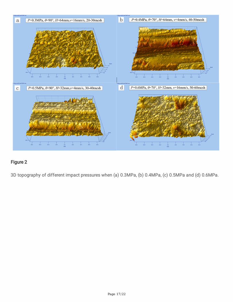
Where it can be found that erosion is affected by many factors, involving nozzle diameter(D), standoffdistance(S), impact pressure(P), traverse speed(u), impact angle(α), and material properties of abrasiveand workpiece, such as average diameter of abrasive particle(d), velocity of abrasive particles(v),abrasive density(ρa), elastic modulus of workpiece(E), workpiece hardness(Hw), workpiece density(ρw).Others are expressed as constants. There are also some default factors, such as nozzle diameter. It isignored in this article because it is a supporting device. The roughness inspected by the 3-D opticalpro�ler is shown in Fig. 2. The roughness Sa was measured as 0.343 μm, 2.548 μm, 0.838 μm and 1.605μm in order from Fig. 2(a)-(d), respectively. Obvious impact pits and plough marks were observed due to
Page 7/22
particle erosion. However, the release agent is left in areas that are not eroded by the particles. Theadhesion of the paint is affected by poor removal conditions. The results of this study are similar to theRef. [20].
The test results show that the poor removal effect is caused by the smaller impact pressure, as shown inFig. 2(a). Compared with other pressures, elastic impact is mostly displayed except for the areas whereplastic deformation occurs. The same appears in other impact pressures. And these plastic deformationcraters are exhibited due to the impact of larger particles. However, the discontinuity of the impact crateris due to the longer particle travel (large impact distance) and faster transverse velocity. Therefore, impactcan be ignored under normal erosion and low pressure conditions. The smoothness is maintained andmost of the release agent remains. Even if the particle travel distance is large, the traces of the plough areshown in Fig. 2(b) at extremely low traverse speed. This is due to the oblique erosion with an erosionangle, the increase in impact pressure and also due to the smaller particle size. However, not all normalerosions are bad, and not all oblique impacts are good. This view is proved in Fig. 2. (C) and (d). Theplough was shown under normal impact and a low lateral speed, but the plough was lonely and did notspread in Fig. 2(c). This is attributed to the uneven distribution of particles in the jet due to the largerparticle size. The unsatisfactory erosion is shown in Fig. 2(d), which is attributed to the larger lateralvelocity, but other conditions are ideal, including oblique impact with erosion angle, larger impactpressure and smaller particle size. The in�uence of these parameters corresponds to the Eq. (1). Insummary, a more ideal surface is shown in Fig. 2(b). Although the surface roughness Sa is too large, therelease agent is basically removed and can be observed from the �gure. The particle erosion effect isbene�cial to adhesion. In addition, the continuous surface favorable for adhesion is determined, and theerosion process is strictly controlled. The average roughness is about 2 μm.
3.2 Mechanism
The surface morphology and state due to the process has been reviewed in detail. The erosionmechanism will be analyzed in detail in the following process. The erosion rate of CFRP is shown in Fig.3. The sketch diagram of erosion mechanism and SEM morphological analysis are shown in Fig. 4 and 5,respectively.
The carbon �ber bundle is wrapped by epoxy resin, and the release agent near the nozzle on the surfaceof the workpiece is eroded when the abrasive hits the workpiece. Erosive wear of abrasive is a typicalwear mode, which is the material loss caused by repeated impact of �ne solid particles[21]. The researchresults of many scholars have been summarized, there is two types of erosion wear, brittle erosion toremove material formed by cracks generation and extension, and ductile erosion to remove material frommicro-cutting and ploughing. This difference depends on the erosion rate (ER) as a function of impactangle[22]. Brittle erosion has been proved by some scholars[18,22,23] under particles eroded onthermosetting polymer; plastic (semi-ductile) erosion has been proven by other scholars[24-27]. Themaximum erosion rate of plastic erosion is achieved at an erosion angle of 30°, brittle erosion occurs at90°, and semi-ductile erosion occurs at 50-70°. Until now, there is no precise statement about the polymer

Page 8/22
corrosion mechanism, because particle erosion has a strong dependence on material properties anddifferent experimental conditions. The maximum erosion rate occurs at 50-70° under impact pressures of0.32 and 0.38 MPa in this study (Figure 3).
The specimens were eroded for 0.5 min at different impingement angle and impact velocity and eachtime the weight loss (Δw) was measured after machining. This procedure was repeated for 5 times for atotal exposure time of 2.5 min until the erosion rate attains a constant steady-state value. The erosionwear rate (Er) in g/g was calculated as per the following formula:
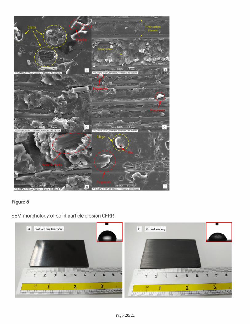
Where Δw is the mass loss of CFRP in g, and we is the initial mass of CFRP in g. It should be noted thatthe erosion rate is calculated through the mass loss in the experiment. Compared with large angles,tangential erosion plays an important role in cutting and ploughing under low angle erosion conditions.This view is fully proved by Zhao et al.[28]. The particle erosion mechanism of CFRP is shown in Figure 4.Includes two modes: elastic fatigue erosion and ductile erosion. Among them, ductile erosion includesthree form: micro-cutting and ploughing, accumulation into "ridges" and large pieces falling off. A largepiece fell off described here can be roughly understood as brittle erosion, because no better explanationhas been found, but it actually exists(Figure 5 (a)).
However, ductile or brittle erosion mechanism is not absolute because smaller particles tend to make thematerial removal behaviour more ductile[29], and the AFWAL-MLBE E glass-epoxy composites exhibitedsemi-ductile erosion behavior[30]. The obvious groove traces can be seen in Fig. 2(b) and (c), which arecaused by particle sliding, micro cutting and ploughing. There are “�sh scales” with ductile erosion, �akeaccumulation and plough marks can be seen from Fig. 5(b-f), which illustrates the plastic deformationthat occurred during the impact. Finnie[31] �rst proposed the micro-cutting wear mechanism. The particlewedging into the surface is caused by the vertical partial velocity, while the particle sliding along thesurface is caused by the tangential partial velocity. The "plough" effect is caused by the combination ofspeeds in two directions [32]. Material removal is caused by the shear action and the micro-cutting of theparticles at high traversing speed on the solid surface. The resin matrix impacted by the particles isconsidered to be in a semi-ductile cutting state when the particles come into contact with the material ata large angle or strike vertically. Hutchins et al.[33] elaborated on this point of view. The erosionmechanism is a process in which sheet-like wall materials are continuously generated and disappearedon the surface of the material. These uplifted ridges and lip-shaped sheets have been repeatedly hit by alarge number of particles for a long time, and the plastic deformation layer is gradually peeled off andremoved[33,34]. The ideal preprocessing state is shown in Fig. 5(d), close to 90% of the epoxy resin layer ispeeled off by impacting. Seven intact carbon �bers were exposed to the scanning electron microscope,and the others were tightly wrapped in epoxy resin. However, individual "fragments" were exposed on the

Page 9/22
washed-out surface. Nevertheless, the pretreatment effect is better. Despite the "boundary conditions" setabove, the carbon �ber damage cannot be avoided in the experiment.
It can be seen from Fig. 5(a) and (f) that about 90% of the epoxy resin layer is not removed, and theimpact pressure is the main factor determining the kinetic energy (velocity) of the particles. Regardless ofthe combination of larger impact pressure and small particle size, or the combination of smaller impactpressure and large particle size, it is impossible to completely remove the epoxy resin due to thedispersion of particles, which is affected by the larger traverse velocity, but the particle impact area willhave a obvious effect on the surface layer. The occurrence and propagation of cracks in the impact zonemay provide evidence for the brittle mechanism. Not only did the crater appear after the impact, but alsopitting and scratches. In addition, the epoxy resin was dropped from the �ber surface in the severe impactarea (A large piece fell off). This phenomenon is undesirable because it is most likely caused by the lowbonding of the polymer to the �ber. These invisible debonding can cause skin failure. Compared withFigure 5(d), the impact effect is worse.
Erosion of abrasive is a complex phenomenon during jet machining. It cannot be summarized as one orseveral erosion mechanisms. Taking into account the in�uence of substrate characteristics, this processcoexists with one or more erosion mechanisms. In general, the essence of particle erosion is energyexchange. Based on the above analysis, the �sh scale fragments, scratches, pitting and ploughing showthat ductile erosion and elastic deformation are exhibited under the process. The occurrence andpropagation of cracks (lateral or longitudinal), the peeling of epoxy group from �ber, and the fatigueimpact of surface particles all indicate the possibility of brittle erosion. In order to provide more support,more in-depth research is needed. Fully consider that the maximum erosion rate occurs at 60°, the semi-tough erosion mechanism is demonstrated by the particle impact CFRP.
3.3 Wettability
The wettability of a solid surface can be described by observing the shape of a drop deposited on thesurface. A surface having a high wettability tends to allow the drop to spread over a relatively wide areaof the surface, thereby wetting the surface. For a surface with low wettability (hydrophobic), the liquidtends to retain a spherical shape[35]. As mentioned in the previous two sections, the CFRP laminatesurface properties is changed by the particle erosion, in other words, the surface wettability of theworkpiece is changed by particle erosion. The contact angle is used to characterize the wettability of thesolid surface, which is the angle formed between the liquid–solid and the liquid–vapor interfaces. Theideal surface wettability promotes liquid molecules to repel each other on the solid surface throughcapillary forces, thereby in�ltrating the solid surface. In general, the contact angle on a smooth surfacewill be greater than π⁄�, indicating that the liquid will not wet the surface and the liquid will keep thedroplet. However, the eroded surface is uneven, with obvious peaks and troughs, and the contact angle ofthe liquid surface is less than π⁄�, which means that the liquid is easy to wet the surface. Therefore, it isnecessary to improve the surface energy in this study in order to increase the adhesion of the coating.The contact angle[36] is given by
Page 10/22
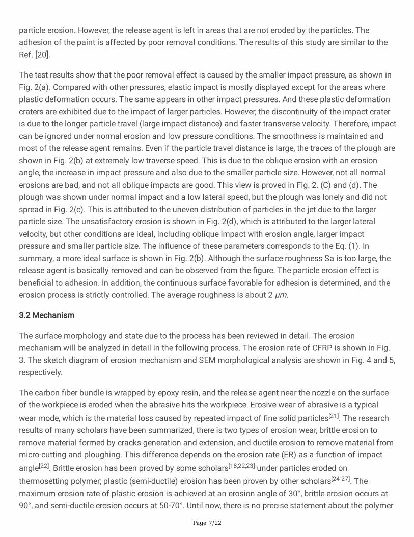
where θeq is the equilibrium contact angle, and subscripts indicate the corresponding interfaces. Theuntreated laminate with a surface roughness Sa of 188nm is shown in Fig. 6(a), and the manual sandingwith a surface roughness Sa of 978nm is shown in Fig. 6(b). The manually sanded samples are quali�edby test of Water �lm continuous test. The continuous ability of the water �lm is re�ected by the contactangle of the droplet penetration. The droplet contact angle was measured by the JC2000DM penetrationangle measuring instrument (produced by Beijing Zhongyi Kexin Technology Co., Ltd.), and then thesurface energy was calculated. In contrast, the surface has better wettability and wider droplet spreading(Fig. 6(b)) under the manual sanding, while the droplets remain hemispherical without pretreatment inFig. 6(a). Compared with untreated, the surface wettability is better after manual sanding. The averagecontact angles are 82.25° and 73.8°, and the surface energy is about 35.598 mN/m and 38.664 mN/m foruntreated laminates and manual sanding, respectively.
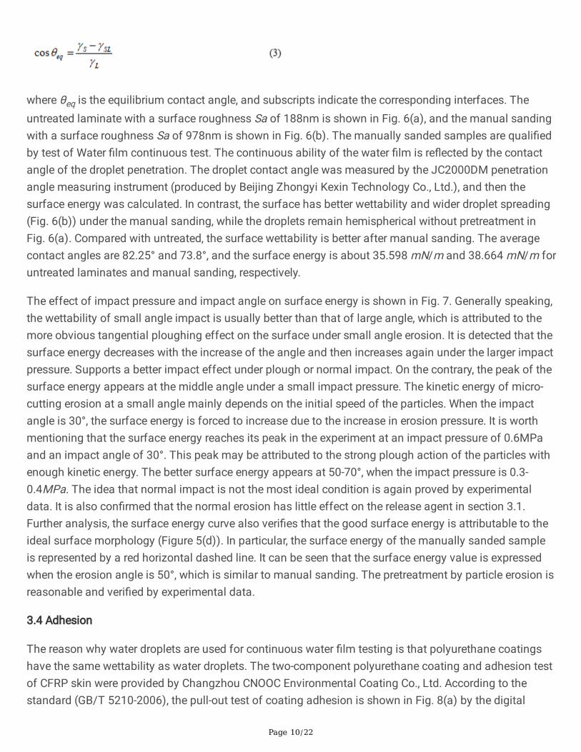
The effect of impact pressure and impact angle on surface energy is shown in Fig. 7. Generally speaking,the wettability of small angle impact is usually better than that of large angle, which is attributed to themore obvious tangential ploughing effect on the surface under small angle erosion. It is detected that thesurface energy decreases with the increase of the angle and then increases again under the larger impactpressure. Supports a better impact effect under plough or normal impact. On the contrary, the peak of thesurface energy appears at the middle angle under a small impact pressure. The kinetic energy of micro-cutting erosion at a small angle mainly depends on the initial speed of the particles. When the impactangle is 30°, the surface energy is forced to increase due to the increase in erosion pressure. It is worthmentioning that the surface energy reaches its peak in the experiment at an impact pressure of 0.6MPaand an impact angle of 30°. This peak may be attributed to the strong plough action of the particles withenough kinetic energy. The better surface energy appears at 50-70°, when the impact pressure is 0.3-0.4MPa. The idea that normal impact is not the most ideal condition is again proved by experimentaldata. It is also con�rmed that the normal erosion has little effect on the release agent in section 3.1.Further analysis, the surface energy curve also veri�es that the good surface energy is attributable to theideal surface morphology (Figure 5(d)). In particular, the surface energy of the manually sanded sampleis represented by a red horizontal dashed line. It can be seen that the surface energy value is expressedwhen the erosion angle is 50°, which is similar to manual sanding. The pretreatment by particle erosion isreasonable and veri�ed by experimental data.
3.4 Adhesion
The reason why water droplets are used for continuous water �lm testing is that polyurethane coatingshave the same wettability as water droplets. The two-component polyurethane coating and adhesion testof CFRP skin were provided by Changzhou CNOOC Environmental Coating Co., Ltd. According to thestandard (GB/T 5210-2006), the pull-out test of coating adhesion is shown in Fig. 8(a) by the digital

Page 11/22
display automatic adhesion tester (Positest-ATA-20A, DeFelsko Corporation, New York, USA. The testrange is 0.7-24 MPa, the resolution is 0.01 MPa, the accuracy is ±1% of full scale, and the standardaluminum dollies diameter is 20 mm). Before the adhesion test is performed, the coated coating must beallowed to stand at room temperature for 7 days. The sticky area of the dollies needs to be sanded with400 grit sandpaper. The dollies has been bonded to the coating surface using a two-component epoxyresin adhesive.
During the test, the adhesion is de�ned as the shearing force of the dollies being pulled out of the primer.The adhesion test results are roughly divided into three types: cohesive fracture (within a layer), adhesivefracture (between layers) and glue failure (coating/ glue). The results of the experiment should beattributed to the primer adhesive fracture in Fig. 8(b). Because the black substrate can be clearly seen.Each test piece was tested twice and the adhesion was average.
The adhesion curves of impact angle, impact distance, lateral velocity and particle size as a function ofimpact pressure are shown in Fig. 9. In particular, the adhesion test value after manual sanded isrepresented by a horizontal line. The study showed that the best adhesion did not appear under themaximum impact pressure. The surface state of oblique impact does not play a decisive role in theadhesion of the experiment. Because the adhesion of normal impact is better than that of oblique impact,under the maximum impact pressure (Fig. 9(a)). Therefore, it is preliminary inferred that the mechanicalinterlock has little effect on adhesion. However, the better value of adhesion appears at an impact angleof 50-70° and an impact pressure of 0.4-0.5 MPa. The judgment about the better surface condition insection 3.2 is correct, as shown in Figure 5(d), which is proved by above view. Similarly, better adhesionoccurs in large-angle erosion, rather than normal erosion. It can be seen from Fig. 9(b) that the erosiondistance (particle running time) shows a trend of �rst increasing and then decreasing under the in�uenceof increasing impact pressure, except for 48mm. In fact, the surface is caused more obvious damage inthe smaller particle erosion distance. Because the smallest erosion distance leads to the best adhesion. Itshows that the in�uence of erosion distance on adhesion is not dominant. But it can be determined thatthe adhesion is relatively poor at the lowest impact pressure. The impact distance effect is not obvious, atthe maximum impact pressure.
The traverse speed in Fig. 9(c) determines the number of particle impacts per unit time. This is amathematical statistics problem. As mentioned above, the material is removed due to repeated impactsof many particles. The erosion of the particles is continued at a reasonable traverse speed, which isbene�cial to the surface morphology and adhesion. Although the average diameter of the impact site of asingle abrasive is about 1/10 of the average particle size[37]. The particle size does not seem to beimportant. However, the erosion mechanism is fatigue shedding due to the impact of a large number ofparticles. The stable erosion is attributed to the smaller particle size in Figure 9(d).
The wettability and surface energy (adhesion) are more prominent when the pressure is higher (excludingnormal erosion), in the above analysis of surface morphology and wettability. Polyurethane coatings andepoxy resins are similar high molecular polymers with the same functional groups. Intermolecular

Page 12/22
hydrogen bonds are more conducive to changes in surface morphology (increasing contact area).Adhesion is more helpful under the additional "mechanical interlock". Of course, the premise for thisresearch to be meaningful is that the substrate is not damaged (the carbon �ber is not damaged).
The protection of the skin is more effective in improving the adhesion of the coating. However, the skincoating is necessary to maintain and repair after a period of �ight. This work needs to be considered andexecuted for ground service engineers. Too strong adhesion caused unnecessary trouble duringmaintenance and repair of damaged coating. Improving the adhesion of the CFRP skin coating andextending the service life without damaging the substrate are the original intentions in this research, butmaintenance and repair of damaged coatings should also be considered. This is also the di�culty in thisresearch.
4 ConclusionsAn experimental study of erosion CFRP with amino thermosetting plastic particles is presented in thispaper. Compared with traditional paint stripping, it is more suitable for CFRP skin coating to use themethod in this article. The ideal state of adhesion is that the surface energy with a wetting angle of 70° is38 mN/m. The carbon �ber �laments are exposed and damaged when the impact pressure is greater than0.4 MPa. The results show that the ideal process conditions are P=0.36 MPa, H=64 mm, θ=70°, v=8mm/s and the particle size is 40-50 mesh. Semi-ductile erosion is the erosion mechanism studied in thispaper. Amino thermosetting particles have broad development prospects due to the advantages ofmultiple recycling and environmental friendliness. This research laid the foundation for follow-upresearch and provided guidance for the pretreatment of aircraft CFRP skins.
DeclarationsAcknowledgment
This work was supported by the China Postdoctoral Science Foundation (2017M611803); Jiangsuscience and technology planning project (industry foresight and common key technologies)(BE2018072); National Key Laboratory of Science and Technology on Helicopter Transmission (NanjingUniversity of Aeronautics and Astronautics) (Grant No. HTL-A-19K04).
Funding (information that explains whether and by whom the research was supported)
This work was supported by The China Postdoctoral Science Foundation(2017M611803), Jiangsuscience and technology planning project (industry foresight and common key technologies) (BE2018072)and National Key Laboratory of Science and Technology on Helicopter Transmission (Nanjing Universityof Aeronautics and Astronautics) ( HTL-A-19K04).
Con�icts of interest/Competing interests (include appropriate disclosures)
Page 13/22
The authors report no declarations of interest.
Availability of data and material (data transparency)
The datasets generated during and/or analyzed during the current study are available from thecorresponding author on reasonable request.
Code availability (software application or custom code)
Not applicable.
Authors' contributions (optional: please review the submission guidelines from the journal whetherstatements are mandatory)
Yangyang Zhao: Conceptualization, Methodology, Data curation, Validation, Formal analysis,Investigation, Writing - Original Draft, Writing - Review & Editing, Visualization.
Wenzhuang Lu*: Conceptualization, Methodology, Resources, Writing - Review & Editing, Supervision,Funding acquisition.
Yansong Zhu: Writing - Review & Editing.
Dunwen Zuo: Conceptualization, Methodology, Supervision, Visualization.
Ethics approval (include appropriate approvals or waivers)
Not applicable.
Consent to participate (include appropriate statements)
Not applicable.
Consent for publication (include appropriate statements)
All authors agree to be published in The International Journal of Advanced Manufacturing Technology.
References1. Soo-Jin Park, Min-Kang Seo. (2011) Chapter 7-Types of Composites. Interface Science and
Technology 18:501-629. https://doi.org/10.1016/B978-0-12-375049-5.00007-4
2. Y. Han, P. Zhang, T.Y. Zheng, H.Y. Fu. (2020) Research progress of forming process of �ber reinforcedpolymer composite grid structure. Acta Materiae Compositae Sinica 4:845-858.https://doi.org/10.13801/j.cnki.fhclxb.20190628.003
3. Maria MRAZOVA (2013) Advanced composite materials of the future in aerospace industry. INCASBULLETIN 5:139 – 150. https://doi.org/10.13111/2066-8201.2013.5.3.14

Page 14/22
4. Rauh, S. Kreling, M. Kolb, M. Geistbeck, S. Boujenfa, M. Suess, K. Dilger (2018) UV-laser cleaning andsurface characterization of an aerospace carbon �bre reinforced polymer. International Journal ofAdhesion & Adhesives 82:50-59. https://doi.org/10.1016/j.ijadhadh.2017.12.016
5. Fengjun Chen. Xiangliang Miao. Yu Tang. Shaohui Yin (2017) A review on recent advances inmachining methods based on abrasive jet polishing (AJP). Int J Adv Manuf Technol 90:785–799.https://doi.org/10.1007/s00170-016-9405-7
�. Roberts (1985) Paint removal through plastic bead blasting—the sensible way[J]. SAE InternationalJournal of Aerospace 94(4):156-158. https://doi.org/10.4271/850712
7. Roberts (1986) Paint removal through plastic media blasting—a dream come true[R]. SAE TechnicalPaper,. https://doi.org/10.4271/860703
�. Ümit Üner, Sezan Orak, Mehmet Alper Sofuoğlu (2016) Effect of plastic media blasting method onmechanical properties of Al 2024-T6 alloy. Journal of Mechanical Science and Technology 30(10):4559-4564. https://doi.org/10.1007/s12206-016-0926-7
9. Dong Sam Park, Myeong-Woo Cho. Honghee Lee (2004) Effects of the impact angle variations onthe erosion rate of glass in powder blasting process. Int J Adv Manuf Technol 23:444–450.https://doi.org/10.1007/s00170-003-1724-9
10. P. Amro (1992) The effect of mechanical paint stripping on the fatigue and fracture of thin aluminumairplane skin. Ph.DThesis, Dissertation. Wichita State University, USA.
11. M. Fan, H.Z. Li, J. Wang, C.Y. Wang (2011) A study of the �ow characteristics in micro-abrasive jets.Experimental Thermal and Fluid Science. (35):1097–1106.https://doi.org/10.1016/j.exptherm�usci.2011.03.004
12. P. Verma, G.K. Lal. (1984) An experimental study of abrasive jet machining. International Journal ofMachine Tool Design and Research 24(1):19-29. https://doi.org/10.1016/0020-7357(84)90043-X
13. Huaizhong Li, Jun Wang, Ngaiming Kwok, Thai Nguyen, Guan Heng Yeoh (2018) A study of themicro-hole geometry evolution on glass by abrasive air-jet micromachining. Journal ofManufacturing Processes 31: 156–161. https://doi.org/10.1016/j.jmapro.2017.11.013
14. H. Neilson. A (1968) Gilchrist. Erosion by a stream of solid particles. Wear 11(2):111-122.https://doi.org/10.1016/0043-1648(68)90591-7
15. J. Lennon, P. J. Mallon (1992) Investigation of the Effects of Plastic Media Blasting (PMB) onAdvanced Composites. Key Engineering Materials 72-74:323-330.https://doi.org/10.4028/www.scienti�c.net/KEM.72-74.323
1�. P. Tilly, W. Sage (1970) The interaction of particle and material behaviour in erosion processes. Wear16(6):447- 466. https://doi.org/10.1016/0043-1648(70)90171-7
17. Arjula, A.P. Harsha (2006) Study of erosion e�ciency of polymers and polymer composites. PolymerTesting 25(2):188-196. https://doi.org/10.1016/j.polymertesting.2005.10.009
1�. Avinash A. Thakre (2015) Prediction of Erosion of Polyetherimide and Its Composites UsingResponse Surface Methodology. Journal of Tribology 137(1):1-7. https://doi.org/10.1115/1.4028267

Page 15/22
19. Yansong Zhu, Wenzhuang Lu, Dunwen Zuo (2019) Development of abrasive jet polishing by usingamino thermosetting plastic abrasive for aluminum alloy. Journal of Manufacturing Processes(43):218-228. https://doi.org/10.1016/j.jmapro.2019.05.016
20. Tianxiang Chen, Chengyong Wang (2012) Investigation into Roughness of Surface Polished byAbrasive Waterjet with Taguchi Method and Dimensional Analysis. Materials ence forum 723:188-195. https://doi.org/10.4028/www.scienti�c.net/MSF.723.188
21. Patnaik, A. Satapathy, N. Chand, N.M. Barkoula, S. Biswas (2010) Solid Particle Erosion WearCharacteristics of Fiber and Particulate Filled Polymer Composites: A Review. Wear (268):249-263.https://doi.org/10.1016/j.wear.2009.07.021
22. Miyazaki, T. Hamao (1994) Solid particle erosion of thermoplastic resins reinforced by short �bres.Comp. Mater (28):871–883. https://doi.org/10.1177/002199839402800905
23. M. Hutchings, R.E. Winter, J.E. Field (1976) Solid particle erosion of metals: the removal of surfacematerial by spherical projectiles. Proc. Roy. Soc. Lond., Ser. A (348):379–392.https://doi.org/10.1098/rspa.1976.0044
24. S. Tewari, A.P. Harsha, A.M. Häger, K. Friedrich (2002) Solid particle erosion of unidirectional carbon�bre reinforced polyetheretherketone composites. Wear (252):992–1000.https://doi.org/10.1016/S0043-1648(02)00063-7
25. Feng Cai, Feng Gao, Shashank Pant, Xiao Huang, Qi Yang (2016) Solid Particle Erosion Behaviors ofCarbon-Fiber Epoxy Composite and Pure Titanium. Journal of Materials Engineering andPerformance (25):290-296. https://doi.org/10.1007/s11665-015-1848-8
2�. Amkee Kim, Ilhyun Kim (2009) Solid particle erosion of CFRP composite with different laminateorientations. Wear 267:1922–1926. https://doi.org/10.1016/j.wear.2009.03.038
27. S. Tewaria, A.P. Harshaa, A.M. Häger, K. Friedrich (2003) Solid particle erosion of carbon �bre– andglass �bre–epoxy composites. Composites Science and Technology 63:549–557.https://doi.org/10.1016/S0266-3538(02)00210-5
2�. Weimin Zhao, Chun Wang, Timing Zhang, Min Yang, Bin Han, Anne Neville (2016) Effects of lasersurface melting on erosion–corrosion of X65 steel in liquid–solid jet impingement conditions. Wear362-363:39-52. https://doi.org/10.1016/j.wear.2016.05.006
29. Finnie (1995) Some re�ections on the past and future of erosion. Wear 186–187:1–10.https://doi.org/10.1016/0043-1648(95)07188-1
30. Zahavi, G.F. Schmitt (1981)Solid particle erosion of reinforced composite materials. Wear 71(2):179-190. https://doi.org/10.1016/0043-1648(81)90337-9
31. Finnie (1960) Erosion of surfaces by solid particles. Wear 3(2):87-103. https://doi.org/10.1016/0043-1648(60)90055-7
32. Xinyu Zhang (1998) Study of Gas—Solid Multiphase Flow Characteristics in Impact Rich/LeanBurners and Curved Ducts. D Thesis, Dissertation, Zhejiang University, China
33. Hutchings, R. Winter, J. Field (1976) Solid particle erosion of metals: The removal of surface materialby spherical projectiles. Proceedings of the Royal Society of London. A. Mathematical and Physical

Page 16/22
Sciences 348(1654):443-457. https://doi.org/10.1098/rspa.1976.0044
34. Bellman, A. Levy (1981) Erosion mechanism in ductile metals. Wear 70(1):443-457.https://doi.org/10.1016/0043-1648(81)90268-4
35. Antonini, M. Innocenti, T. Horn, M. Marengo, A. Amirfazli (2011) Understanding the effect ofsuperhydrophobic coatings on energy reduction in anti-icing systems. Cold Regions Science andTechnology, (67):58–67. https://doi.org/10.1016/j.coldregions.2011.02.006
3�. Young (1805) An essay on the cohesion of �uids. Philosophical Transactions of the Royal Society ofLondon (95):65–87. https://doi.org/10.1098/rstl.1805.0005
37. Djurovic, É. Jean, M. Papini, P. Tangestanian, J.K. Spelt (1999) Coating removal from �ber-composites and aluminum using starch media blasting. Wear (224):22-37.https://doi.org/10.1016/S0043-1648(98)00308-1
Figures
Figure 1
Schematic diagram of experiment device (a) and control system (b).
Page 17/22
Figure 2
3D topography of different impact pressures when (a) 0.3MPa, (b) 0.4MPa, (c) 0.5MPa and (d) 0.6MPa.

Page 18/22
Figure 3
Erosion rate as a function of impact angle.

Page 19/22
Figure 4
Two types removal modes for particles impact workpiece: (a) elastic impact modes; three different formsin ductile erosion modes (b), (c) and (d).
Page 20/22
Figure 5
SEM morphology of solid particle erosion CFRP.

Page 21/22
Figure 6
Sample of CFRP laminate, untreated (a) and manual sanding (b).
Figure 7
In�uence of pressure and angle on surface energy.

Page 22/22
Figure 8
Coating adhesion test process (a) and results (b).
Figure 9
shows the adhesion curve of (a) impact angle, (b) impact distance, (c) traverse speed, and (d) particlesize as a function of impact pressure.