About the Tutorial - tutorialspoint.com · About the Tutorial Next Generation Networks (NGN) is a...
24
Transcript of About the Tutorial - tutorialspoint.com · About the Tutorial Next Generation Networks (NGN) is a...


NGN
i
About the Tutorial
Next Generation Networks (NGN) is a part of present-day telecommunication system,
which is equipped with capabilities to transport all sorts of media, such as voice, video,
streaming audio/video, text, etc. NGN is developed around the concept of packet switching
as in Internet Protocol architecture. It is more efficient and equally complicated and
involves number of systems, equipment, and processing.
Audience
This tutorial is developed for beginners to help them understand the basics of NGN and its
components. . After finishing this tutorial, you would acquire a good know-how of Next
Generation Networks.
Prerequisites
This tutorial requires a basic understanding of computer networking, signal processing,
and telecommunication system. To get the most of this tutorial, the readers are highly
encouraged to learn the required concepts first.
Disclaimer & Copyright
Copyright 2018 by Tutorials Point (I) Pvt. Ltd.
All the content and graphics published in this e-book are the property of Tutorials Point (I)
Pvt. Ltd. The user of this e-book is prohibited to reuse, retain, copy, distribute, or republish
any contents or a part of contents of this e-book in any manner without written consent
of the publisher.
We strive to update the contents of our website and tutorials as timely and as precisely as
possible, however, the contents may contain inaccuracies or errors. Tutorials Point (I) Pvt.
Ltd. provides no guarantee regarding the accuracy, timeliness, or completeness of our
website or its contents including this tutorial. If you discover any errors on our website or
in this tutorial, please notify us at [email protected]

NGN
ii
Table of Contents
About the Tutorial ..................................................................................................................................... i
Audience .................................................................................................................................................... i
Prerequisites .............................................................................................................................................. i
Disclaimer & Copyright .............................................................................................................................. i
Table of Contents ...................................................................................................................................... ii
1. NGN – PULSE CODE MODULATION ....................................................................................... 1
Sampling ................................................................................................................................................... 1
Quantization ............................................................................................................................................. 2
Companding .............................................................................................................................................. 3
Encoding ................................................................................................................................................... 4
2. NGN – MULTIPLEXING ........................................................................................................... 6
Multiplexing.............................................................................................................................................. 6
3. NGN – FRAME STRUCTURE ................................................................................................... 8
Timeslot 1 to 15 and 17 to 31 .................................................................................................................... 8
Timeslot 0 ................................................................................................................................................. 8
Timeslot 16 ............................................................................................................................................... 9
4. NGN - HIGHER ORDER MULTIPLEXING ................................................................................ 12
5. NGN – PLESIOCHRONOUS DIGITAL HIERARCHY ................................................................... 15
PDH Limitations ...................................................................................................................................... 16
6. NGN – SYNCHRONOUS DIGITAL HIERARCHY ....................................................................... 19
SDH – Network Topologies ...................................................................................................................... 20
SDH Network Synchronization ................................................................................................................ 21
SDH Hierarchy ......................................................................................................................................... 22
NGN
iii
STM-1 Frame ........................................................................................................................................... 22
STM-1 Overheads .................................................................................................................................... 23
SDH Path Trace ....................................................................................................................................... 25
SDH Management ................................................................................................................................... 26
SDH Network Resilience .......................................................................................................................... 27
7. NGN - WDM TECHNOLOGY ................................................................................................. 29
DWDM within the Network .................................................................................................................... 32
WDM COMPONENTS .............................................................................................................................. 36
OPTICAL TRANSPORT NETWORKS ........................................................................................................... 37
A Wavelength Cross-Connect Node ......................................................................................................... 38
OTN FRAME FORMAT.............................................................................................................................. 39
An Optical Channel Frame ....................................................................................................................... 39
WDM RINGS ............................................................................................................................................ 40
MESH WDM NETWORKS ......................................................................................................................... 40
WDM Network Infrastructure ................................................................................................................. 41
SDH Frame Encapsulation ....................................................................................................................... 42
SDH Interfaces to WDM .......................................................................................................................... 43
Evolution towards an All-Optical Transport Network .............................................................................. 44
8. NGN – MICRO ELECTRO MECHANICAL SYSTEMS ................................................................. 45
Application of MEMS .............................................................................................................................. 45
Design and Fabrication Techniques ......................................................................................................... 46
All Optical DWDM Networks and MEMS ................................................................................................. 46
Breakthrough in Optical Switching .......................................................................................................... 47
Optical Add Drop Multiplexer ................................................................................................................. 47
Optical Cross Connect ............................................................................................................................. 47

NGN
iv
9. NGN – TYPES OF WDM ........................................................................................................ 49
WDM ...................................................................................................................................................... 49
CWDM .................................................................................................................................................... 49
DWDM .................................................................................................................................................... 49
NGN
5
The advent of high-speed voice and data communications has brought about the need for a
fast medium for transporting the information. Digital circuits or links have evolved from the
need to transmit voice or data in digital form.
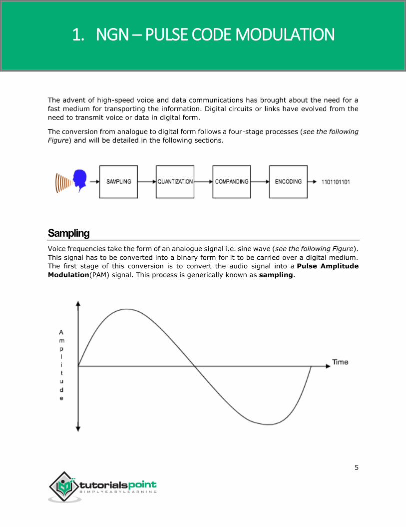
The conversion from analogue to digital form follows a four-stage processes (see the following
Figure) and will be detailed in the following sections.
Sampling
Voice frequencies take the form of an analogue signal i.e. sine wave (see the following Figure).
This signal has to be converted into a binary form for it to be carried over a digital medium.
The first stage of this conversion is to convert the audio signal into a Pulse Amplitude
Modulation(PAM) signal. This process is generically known as sampling.
1. NGN – PULSE CODE MODULATION

NGN
6
The sampling process must gather sufficient information from the incoming voice frequencies
to enable a copy of the original signal to be made. Voice frequencies are normally in the range
of 300Hz to 3400Hz, typically known as the commercial speech band.
To obtain a sample, a sampling frequency is applied to the original voice frequency. The
sampling frequency is determined by the Nyquist Sampling Theorem, which dictates that
“the frequency of sampling should be at least twice the highest frequency
component.”
This ensures that a sample is taken a minimum of once in each half cycle, thus, eliminating
the possibility of sampling at zero points of the cycle, which would have no amplitude. This
results into the sampling frequency being a minimum of 6.8 KHz.
The European standard samples an incoming signal at 8 KHZ, ensuring a sample, is taken
every 125micro seconds or 1/8000th of a second (see the following Figure ).
Quantization
The amplitude of each sample would ideally be assigned a binary code (1’s or 0’s), but as
there can be an infinite number of amplitudes; therefore, there need to be an infinite number
of binary codes available. This would be impractical, so another process has to be employed,
which is known as quantizing.
Quantizing compares the PAM signal against a quantizing scale, which has a finite number of
discrete levels. The quantizing scale splits into 256 quantizing levels, of which, 128 are
positive levels and 128 are negative levels.
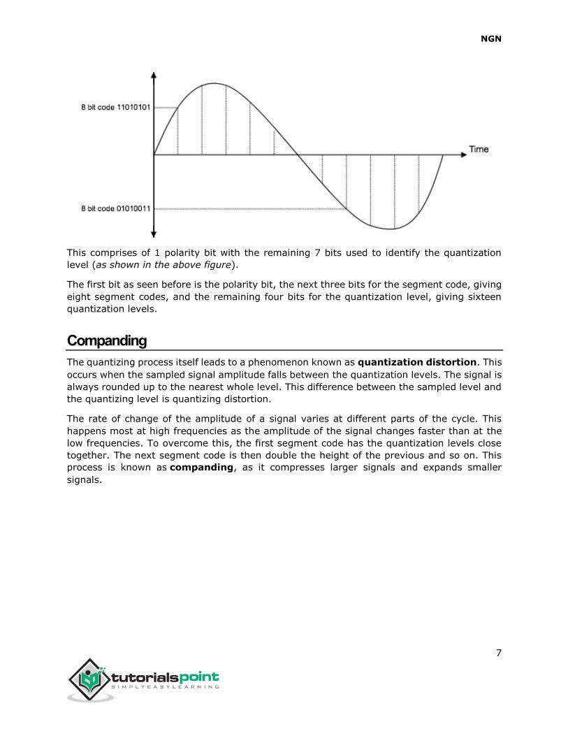
The quantization stage involves allocating a unique 8 bit binary code appropriate to the
quantizing interval into which the amplitude of the PAM signal falls (see the following Figure).
NGN
7
This comprises of 1 polarity bit with the remaining 7 bits used to identify the quantization
level (as shown in the above figure).
The first bit as seen before is the polarity bit, the next three bits for the segment code, giving
eight segment codes, and the remaining four bits for the quantization level, giving sixteen
quantization levels.
Companding
The quantizing process itself leads to a phenomenon known as quantization distortion. This
occurs when the sampled signal amplitude falls between the quantization levels. The signal is
always rounded up to the nearest whole level. This difference between the sampled level and
the quantizing level is quantizing distortion.
The rate of change of the amplitude of a signal varies at different parts of the cycle. This
happens most at high frequencies as the amplitude of the signal changes faster than at the
low frequencies. To overcome this, the first segment code has the quantization levels close
together. The next segment code is then double the height of the previous and so on. This
process is known as companding, as it compresses larger signals and expands smaller
signals.

NGN
8
In Europe they use the A-law of companding, compared to North America and Japan who use
the µ law.
As quantization distortion is equivalent to noise, companding improves the signal to noise
ratio on low amplitude signals, and produces an acceptable signal to noise ratio over the
complete range of amplitudes.
Encoding
In order for the binary information to be transmitted over a digital path, the information has
to be modified into a suitable line code. The encoding technique employed in Europe is known
as High Density Bipolar 3 (HDB3).
HDB3 is derived from a line code called AMI or Alternate Mark Inversion. Within AMI
encoding, there are 3 values used: no signal to represent a binary 0, and a positive or negative
signal that is used alternately to represent a binary 1.
One problem associated with AMI encoding occurs when a long string of zeros are transmitted.
This can cause phase lock loop problems at the distant end receiver.
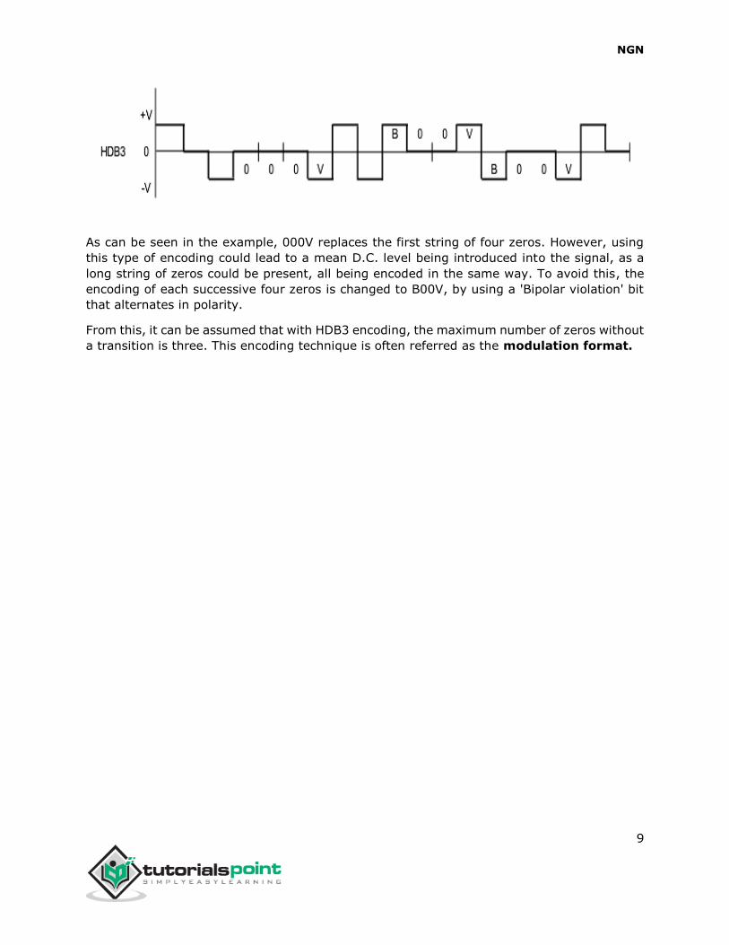
HDB3 works in a similar way to AMI, but incorporates an extra encoding step that replaces
any string of four zeros by three zeros followed by a 'violation bit.’ This violation is of the
same polarity of the previous transition (see the following Figure).
NGN
9
As can be seen in the example, 000V replaces the first string of four zeros. However, using
this type of encoding could lead to a mean D.C. level being introduced into the signal, as a
long string of zeros could be present, all being encoded in the same way. To avoid this, the
encoding of each successive four zeros is changed to B00V, by using a 'Bipolar violation' bit
that alternates in polarity.
From this, it can be assumed that with HDB3 encoding, the maximum number of zeros without
a transition is three. This encoding technique is often referred as the modulation format.

NGN
10
Multiplexing
So far, we have been concentrating only on one voice channel. Now, we need to combine a
number of these channels into a single transmission path, a process known as multiplexing.
Multiplexing is a process employed whereupon several channels can be combined, in order
for them to be transmitted over a single transmission path. The process commonly in use in
telephony is known as Time Division Multiplexing (TDM).
As we have seen before, sampling for one channel takes place every 125 micro seconds.
This makes it possible to sample other channels during this period. In Europe, the time span
is divided into 32 time periods, known as timeslots. These 32 timeslots can then be grouped
together to form a frame (see the following figure).
Consequently, the time duration of a frame can be considered as 125micro seconds. It can
now also be assumed that as each timeslot consists of 8 data bits, and is repeated 8000 times
a channel rate of 64000 bits per second or 64Kbits is attainable. With this information it is
now possible to determine the total number of data bits transmitted over the single path,
known as the system bit rate. This is calculated using the following formula:
System bit rate = Sampling frequency x Number of timeslots x Bits per timeslot
= 8000 x 32 x 8 = 2048000 bits/sec = 2.048 Mbits
2. NGN – MULTIPLEXING

NGN
11
Of the 32 channels available, 30 are used for speech transmission, and the remaining 2
timeslots are used for alignment and signalling. The following section will explain the function
of all the timeslots.

NGN
12
Timeslot 1 to 15 and 17 to 31
These 30 timeslots are available for the transmission of the digitized analogue signal in 8-bit
form, with a bandwidth of 64 kbit/s (e.g. the customers’ data).
Timeslot 0
The European recommended system defines that the Timeslot 0 of each frame is used for
synchronization, also known as frame alignment (see the following Figure). This ensures
that the timeslots in each frame are aligned between the transmitting station and the receiving
station.
The frame alignment word (FAW) is carried in data bits 2 to 8 of each even frame, while
the odd frames carry a not frame alignment word (NFAW) in data bit 2 (see the following
Figure).
3. NGN – FRAME STRUCTURE
NGN
13
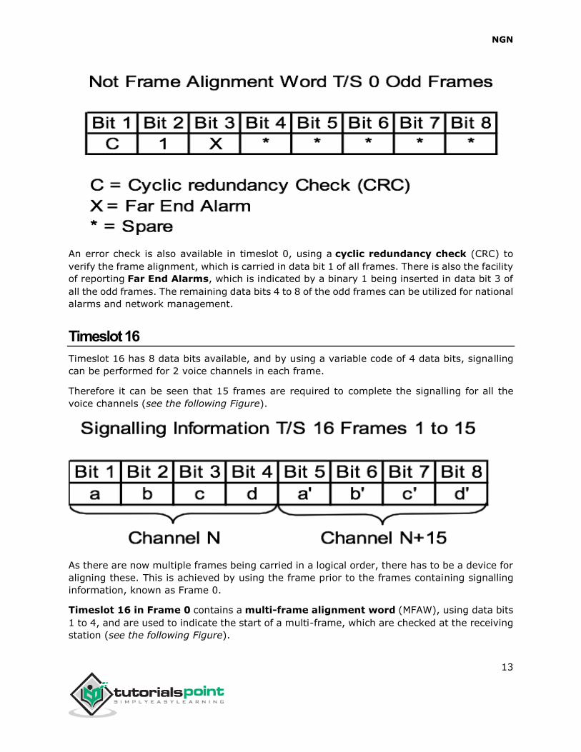
An error check is also available in timeslot 0, using a cyclic redundancy check (CRC) to
verify the frame alignment, which is carried in data bit 1 of all frames. There is also the facility
of reporting Far End Alarms, which is indicated by a binary 1 being inserted in data bit 3 of
all the odd frames. The remaining data bits 4 to 8 of the odd frames can be utilized for national
alarms and network management.
Timeslot 16
Timeslot 16 has 8 data bits available, and by using a variable code of 4 data bits, signalling
can be performed for 2 voice channels in each frame.
Therefore it can be seen that 15 frames are required to complete the signalling for all the
voice channels (see the following Figure).
As there are now multiple frames being carried in a logical order, there has to be a device for
aligning these. This is achieved by using the frame prior to the frames containing signalling
information, known as Frame 0.
Timeslot 16 in Frame 0 contains a multi-frame alignment word (MFAW), using data bits
1 to 4, and are used to indicate the start of a multi-frame, which are checked at the receiving
station (see the following Figure).

NGN
14
Data bit 6 can be used to indicate distant multi-frame alignment loss (DLMFA). As can be
seen, a multi-frame consists of all the frames required to complete all speech and signalling
operations, i.e. 16 frames, and is known as a multi-frame (see the following Figure).
The duration of a multi-frame can be calculated using the following:
Duration of multi-frame = Number of frames × duration of frame
NGN
15
= 16 × 125 micro seconds
= 2000 micro seconds
= 2 milliseconds
The remaining channels are all usable for voice or data transmission, and are known as
timeslots 1 to 15 and 17 to 31, and equate to channels numbered 1 to 30.
FAW = Frame Alignment Word
MFAW = Multi-frame Alignment Word
DATA = 8 bit data words
SIG = CAS signalling timeslot

NGN
16
The Plesiochronous Digital Hierarchy (PDH) has been developed in stages from the basic 30-
channel PCM (PCM-30) system.
As can be seen in the following Figure, there are three different hierarchical systems available,
each supporting different line rates and multiplexing rates. The higher aggregate rates can
therefore be achieved by grouping together the lower rates through the use of multiplexers.
The higher bit rate links also require additional bits for framing and control. For example, an
8.4 Mbits signal comprises of 4 × 2.048 Mbits = 8.192 Mbits, with the remaining 256 Kbits
being used for framing and control.
The European and North American hierarchy systems are often referred by the letter ‘E’ for
European and ‘T’ for North American, with the hierarchy levels being numbered consecutively.
These hierarchy levels can be compared in the following Figure:
4. NGN - HIGHER ORDER MULTIPLEXING

NGN
17
Hierarchy Level Bit Rate (Mbits) Voice Channels
North America
T1 1.544 24
T2 6.312 96
T3 44.736 672
T4 274.176 4032
European
E1 2.048 30
E2 8.448 120
E3 34.368 480
E4 139.264 1920
Not Defined 565.148 7680
These bit rates are often abbreviated to 1.5 meg, 3 meg, 6 meg, 44 meg, 274 meg and 2
meg, 8 meg, 34 meg, 140 meg, and 565 meg respectively.
As the legacy of PDH is so prominent in the telecommunications industry, it became necessary
to accommodate these line rates in any new technology to be introduced, therefore many of
the PDH line rates are supported by the Synchronous Digital Hierarchy (SDH). The only
exception to this is the omission of the 8.4 Mbits level, which no longer has any practical
meaning and is not supported by SDH.
In the basic 2 Mbits system, the data is byte interleaved, whereby each 8-bit timeslot is sent
one after the other. In the case of the higher hierarchy levels, the data streams are
multiplexed together bit-by-bit. A disadvantage of this system is that the bit rate of each
tributary signal can vary from the nominal value due to each multiplexer having their own
independent clock supplies. These clock deviations are dependent on the line rate and can be
compensated for by using justification techniques within the bandwidth remaining after the
multiplexing stage. The line rate also dictates the line code used for transmission as can be
seen below:

NGN
18
Bit Rate
(Mbits)
Number of
64 Kbit
Channels
Permitted
clock
deviation
(ppm)
Interface
code
Preferred medium/line code
Balanc
ed Coaxial
Optical
Fiber
2.048 30 ±50 AMI HDB3
8.448 120 ±30 HDB3 HDB3 HDB3
34.368 480 ±20 HDB3 HDB3
4B3T
2B1Q 5B6B
139.264 1920 ±15 CMI 4B3T 5B6B
NGN
19
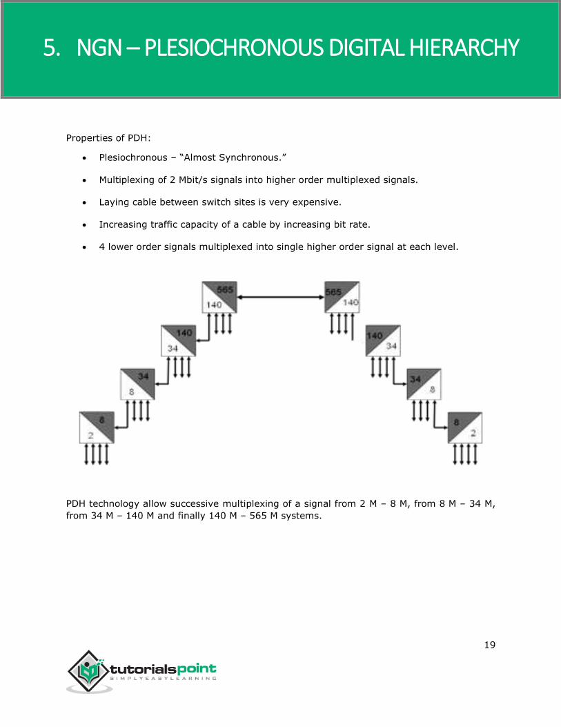
Properties of PDH:
Plesiochronous – “Almost Synchronous.”
Multiplexing of 2 Mbit/s signals into higher order multiplexed signals.
Laying cable between switch sites is very expensive.
Increasing traffic capacity of a cable by increasing bit rate.
4 lower order signals multiplexed into single higher order signal at each level.
PDH technology allow successive multiplexing of a signal from 2 M – 8 M, from 8 M – 34 M,
from 34 M – 140 M and finally 140 M – 565 M systems.
5. NGN – PLESIOCHRONOUS DIGITAL HIERARCHY

NGN
20
There also existed “jump” or “skip” muxes that would allow multiplexing of 16 2 M signals
into a 34 M signal without the intermediate 8 M level.
PDH Limitations
Synchronization: The data is transmitted at regular intervals. With timing derived from the
transmitter’s oscillator, the data is sampled at the same rate as it is being transmitted.
The data is transmitted at regular intervals. With timing derived from the transmitter’s
oscillator, the data is sampled at a slower rate than the transmitter. One of the disadvantages
of PDH was that each element was synchronized independently. For data to be received
correctly, the sampling rate at the receiver end must be the same as the transmission rate at
the transmitter end.

NGN
21
The data is transmitted at regular intervals. With timing derived from the transmitter’s
oscillator, the data is sampled at a faster rate than the transmitter. If the oscillator at the
receiver end was running slower than that at the transmitter end the receiver would miss
some of the bits of the transmitted signal.
Or, if the receiver clock was running faster than that of the transmitter, the receiver would
sample some of the bits twice.

NGN
22
Justification bits are added to lower order signals so that they can be multiplexed at a single
rate. The equipment oscillator is used as a timing source for the bit rate adaption process on
the lower order and also on the multiplex proceed. Justification bits are discarded at the
received end when the signals are de-multiplexed.
Because of the synchronization methods that were used, it was impossible to de-multiplex
from a high order signal to the lowest order tributary signal in one piece of equipment. It was
necessary to de-multiplex at all levels to access the signal that was being dropped at a site
and then re-multiplex all the other channels back up to the higher rate. This meant that there
had to be a lot of equipment on the site to accomplish this. This is known as the PDH Mux
Mountain. All this equipment took up a lot of space on the site and also increased the need
for spares to be held on sites.
Lack of resilience in PDH networks meant that if a fiber break occurred, the traffic would be
lost. PDH network management simply reports alarms to NOC operators. No diagnosis or
remedial tools are available to NOC staff. A maintenance engineer need to be sent on the site
with a minimum amount of information. Each network element requires a connection to the
DCN network as no facilities exist to carry management information across the PDH network.
Lack of standards for interconnection meant that it was not possible to interconnect equipment
from multiple vendors. Equipment could operate on different wavelength, use different bit-
rates, or proprietary optical interfaces.

NGN
23
End of ebook preview
If you liked what you saw… Buy it from our store @ https://store.tutorialspoint.com