Able Marine Energy Park Site Investigation Interpretative ...
40
Annex 31.3 Able Marine Energy Park Site Investigation Interpretative Report (Black & Veatch)
Transcript of Able Marine Energy Park Site Investigation Interpretative ...

Annex 31.3
Able Marine Energy Park
Site Investigation
Interpretative Report
(Black & Veatch)

ENVIRONMENTAL RESOURCES MANAGEMENT ABLE UK LTD.
X.X1

Able Marine Energy Park
Site Investigation Interpretative Report
April 2011

This page intentionally blank

Able UK Ltd 121726 / Site Investigation Interpretative Report
Black & Veatch Ltd Site Investigation Report / April 2011 (i)
SITE INVESTIGATION INTERPRETATIVE REPORT
CONTENTS
1. INTRODUCTION 1 1.1 Background .................................................................................................................... 1 1.2 Site Location .................................................................................................................. 1 1.3 Existing Reports ............................................................................................................ 1 1.4 Objectives ...................................................................................................................... 2
2. PROPOSED CONSTRUCTION WORKS 3 2.1 Construction of New Flood Defence Embankments .................................................... 3 2.2 Creation of New Habitat ............................................................................................... 3 2.3 Breaching of Existing Embankments ........................................................................... 3
3. SITE CONDITIONS 4 3.1 Topography .................................................................................................................... 4 3.2 Geology ......................................................................................................................... 4 3.3 Hydrogeology ................................................................................................................ 5 3.4 Conceptual Site Model .................................................................................................. 5
4. ENGINEERING PROPERTIES 6
5. ENGINEERING ISSUES 7 5.1 Bearing Capacity ........................................................................................................... 7 5.2 Consolidation and Settlement ....................................................................................... 7 5.3 Embankment Fill ........................................................................................................... 7 5.4 Trial Embankment ......................................................................................................... 9 5.5 Breaching the Existing Defence ................................................................................. 10 5.6 Embankment Seepage and Stability Models ............................................................. 10
6. MASS BALANCE CALCULATION 15 6.1 Spoil Produced During the Works ............................................................................. 15 6.2 Fill Required During Embankment Construction ..................................................... 15 6.3 Source and Likely Volume of Fill on Site ................................................................. 15 6.4 Topsoil ........................................................................................................................ 16 6.5 Surplus Spoil .............................................................................................................. 16
7. LAND CONTAMINATION 17 7.1 Chemical Analysis of Soils at Cherry Cobb Sands ................................................... 19
8. WASTE 22
9. CONCLUSIONS AND RECOMMENDATIONS 23 9.1 Geology and Hydrogeology ....................................................................................... 23 9.2 Engineering Issues ...................................................................................................... 23 9.3 Mass Balance Calculations ........................................................................................ 25 9.4 Land Contamination ................................................................................................... 26 9.5 Waste .......................................................................................................................... 26 9.6 Unexploded Ordnance ................................................................................................ 27
10. REFERENCES 28

Able UK Ltd 121726 / Site Investigation Interpretative Report
Black & Veatch Ltd Site Investigation Report / April 2011 (ii)
Figure 1: Site Location Plan Figure 2: Site Investigation Positions Figure 3: Conceptual Site Model Figure 4: Design Flood Hydrograph Figure 5: Seepage Model Output Figure 6: Long Term Stability Model Output Figure 7: Short Term Stability Model Output Figure 8: Historic Drainage Channels
Details of document preparation and issue:
Version no.
Prepared by Reviewed by Authorised for issue Issue date Issue status
1 M Buckley J L Petrie April 2011 April 2011 FINAL DRAFT
B&V project no. 121726 Client’s reference no. TBC
Notice:
This report was prepared by Black & Veatch Limited (BVL) solely for use by Able UK Ltd. This report is not addressed to and may not be relied upon by any person or entity other than Able UK Ltd for any purpose without the prior written permission of BVL. BVL, its directors, employees and affiliated companies accept no responsibility or liability for reliance upon or use of this report (whether or not permitted) other than by Able UK Ltd for the purposes for which it was originally commissioned and prepared.
In producing this report, BVL has relied upon information provided by others. The completeness or accuracy of this information is not guaranteed by BVL.
Black & Veatch Ltd Site Investigation Report / April 2011 iii
EXECUTIVE SUMMARY Able UK Ltd propose to construct a major new deep water facility on the south bank of the Humber Estuary at Killingholme Marshes, within an area of internationally designated habitat. If the development is approved, compensation habitat is expected to be required as a condition of the consent. A potential compensation site has been selected at Cherry Cobb Sands, which has an area of around 100ha and is adjacent to the north bank of the Humber Estuary, opposite Killingholme Marshes. A site investigation was undertaken at Cherry Cobb Sands to evaluate its suitability for development as compensation habitat. Able UK employed Delta Simons to carry out the site investigation and B&V were commissioned to review and interpret the resulting data. The development at Cherry Cobb Sands will require the construction of around 3km of new earth embankment flood defence along the northern boundary of the site. The defence is expected to be up to 5.0m high and Able’s preference is that the embankment is constructed from site won fill. The geological stratigraphy at the site comprises Topsoil over Warped Soil over Estuarine Alluvium to a depth of 15m or more over Glacial Deposits. An area of Landfill was also identified in the north western corner of the site. The groundwater table is expected to be at a depth of around 1.5m. The Warped Soil is typically around 1.5m thick and comprises (soft to) firm, sandy clay and sandy silts. In general terms the cohesive (sandy clay) Warped Soil appears to be toward the eastern end of the site and the non-cohesive (sandy silt) soils tend to be in the central and western parts of the site. The Estuarine Alluvium comprises fine grained silty sands and sandy silts interbedded with organic silty clays and occasional peat strata. The sands and silts are the dominant soil types. The Warped Soil and Estuarine Alluvium in the top 1.0m to 1.5m of the soil profile has dried and formed a crust which is firmer than the underlying soils. These near surface soils should be sufficient to support a 4.0m to 5.0m high embankment, although excavations to form a foundation stratum should be kept to a minimum. The Warped Soil and Estuarine Alluvium will consolidate under load as the new embankment is constructed, leading to settlement of the embankment crest. However, the majority of the Estuarine Alluvium is composed of silts and sands which will probably consolidate during construction and so long term settlement is likely to be limited to around 200mm to 300mm. Models were developed to evaluate seepage through the embankment and embankment stability during normal operation and a significant flood event. An embankment that is constructed with a slope gradient of 1 vertical to 3 horizontal and a 4m wide crest using adequately compacted clay soils is shown to be stable during all of the conditions modelled. The models also indicate that seepage flow at the landward toe is likely to be low.
The most likely on site source of embankment fill is the cohesive Warped Soil in the upper 1.5m of the soil profile. However, the Warped Soil is cohesive in certain areas and non-cohesive in other parts of the site. The non-cohesive soils are unlikely to be suitable for use as fill and, because it may be very difficult to identify the suitable cohesive soils by visual examination, fill selection in the borrow areas is likely to be problematic. Additional site investigations are recommended to enable the Warped Soils to be characterised in more detail and increase certainty that sufficient, suitable fill can be won on site. The cohesive Warped Soil typically comprises silty clays with a natural moisture content of around 30% and is too wet to use as embankment fill without significant drying. Air drying is unlikely to provide certainty in the provision of a suitable fill and so lime will probably be needed to reduce the moisture content to an acceptable level.

Black & Veatch Ltd Site Investigation Report / April 2011 iv
The side walls of borrow excavations are likely to be unstable below 1.5m depth. The soils at the base of the borrow excavations may be soft or loose and so precautions are required to ensure that excavation plant do not become bogged. If it is not possible to identify suitable site won cohesive soils for use in embankment construction, then it should be possible to construct an embankment using imported Glacial Till. The Till at the site is too deep to make excavation viable; however, it is likely to be at the ground surface at a number of locations around 5km to the north of the site. The Till could be used as a core in an embankment constructed from site won soil, reducing the volume of soil that needs to be imported. A trial embankment would assist in the development of a suitable and cost effective construction methodology and is particularly useful in areas where there are concerns regarding the quality of site won fill. Therefore, consideration should be given to the construction of a trial embankment prior to the commencement of the main site development. Preliminary mass balance calculations suggest that the embankment will require around 250,000m3 of fill and, assuming that a site wide reduction in the ground elevation is not be required, the site development is unlikely to produce significant volumes of surplus soil. Most of the soils at the site do not contain evidence of contamination and are likely to be chemically suitable for re-use on site. However, the site investigations identified landfill impacted soils at the western end of the site which contained evidence of asbestos and had a very strong volatile organic compound (VOC) and hydrocarbon odour. These soils are unlikely to be suitable for re-use on site and it is recommended that they are not disturbed during the site development. There are also likely to be other filled historic drainage channels at the site and, whilst none are recorded as landfills, some may have been filled with potentially polluting materials. Additional site investigations are needed to evaluate these areas in more detail. It is unlikely that natural, unpolluted soils excavated at the site and re-used in embankment construction would be classed as waste. The works are also unlikely to produce surplus soil and it is recommended that the landfill impacted soils are not excavated during the works. Therefore, the works are unlikely to produce significant volumes of waste soil. Finally, there is a risk of encountering unexploded ordnance (UXO) in borrow excavations and other site development works and so it is recommended that a detailed UXO survey and risk assessment is carried out prior to the commencement of detailed design works.

Black & Veatch Ltd Site Investigation Report / April 2011 1
SITE INVESTIGATION INTERPRETATIVE REPORT
1. INTRODUCTION
1.1 Background
Able UK Ltd (Able) propose to construct a major new deep water facility on the south bank of the Humber Estuary at Killingholme Marshes. This will involve developing some of the internationally designated areas of the Humber Estuary for industrial use. If the development is approved, compensation habitat is expected to be required as a condition of the consent. Natural England has advised Able that any habitat compensation should be provided in the middle estuary. Black & Veatch (B&V) were commissioned by Able to undertake a site selection process to identify suitable areas for the creation of 100 ha of compensation habitat on Crown Estate land. The assessment (B&V, 2010) identified a number of potential sites, and one of these areas, shown on Figure 1, is now being considered for more detailed appraisal. B&V were commissioned by Able in Nov 2010 to carry out a desk study at the site, design an appropriate site investigation and interpret the resulting data. The desk study and site investigation design were completed in December 2010 (B&V, 2010a). The site investigation was undertaken in February 2011 and this report is an interpretation of the resulting site investigation data. An appraisal of the proposed deep water facility works at Killingholme Marshes is beyond the scope of this assessment.
1.2 Site Location
The area of compensation habitat (the site) is located adjacent to the north bank of the Humber Estuary, opposite the proposed new deep water facility at Killingholme Marshes. The eastern boundary of the site is west of Stone Creek (NGR TA 233192) and the western boundary is at Cherry Cobb Sands (NGR TA 213218). The southern boundary of the site is the existing flood defences adjacent to the Humber Estuary and the northern boundary is Cherry Cobb Sands Road, the minor public highway between Cherry Cobb Sands and Stone Creek. The location of the proposed compensation habitat site is shown on Figure 1.
1.3 Existing Reports
This site investigation interpretation report follows on from the Black & Veatch Desk Study (B&V, 2010a).
Summary Desk Study and Site Investigation Design Report. Black & Veatch. December 2010.
The site investigation was undertaken for Able by Delta Simons in February 2011 and the data obtained is reported in the Site Investigation Factual Report (Delta Simons, 2011).
Site Investigation Factual Report. Delta Simons. March 2011. The site investigations involved the construction of 1 borehole (BH) to a depth of 15.65m, 14 trial pits (TP) to a maximum depth of 4.10m and 12 cone penetration tests (CPT) to a maximum depth of 25.07m. Samples were collected from the BH and TP and tested in the laboratory to determine a range of geotechnical and geo-environmental properties.

Black & Veatch Ltd Site Investigation Report / April 2011 2
1.4 Objectives
The following report interprets the site investigation factual data and provides recommendations on the development of the site. The objectives of the assessment are to:
Determine whether the ground conditions in the area are suitable for the proposed development.
Evaluate the suitability of site won excavated soil for re-use in the construction of earth embankments and other earthworks at the site.
Evaluate risks associated with potential land contamination.

Black & Veatch Ltd Site Investigation Report / April 2011 3
2. PROPOSED CONSTRUCTION WORKS
The development of the site is likely to require a range of construction activities and typically these will involve the excavation, movement and placement of soil to form new flood defence earth embankments and other earthworks.
2.1 Construction of New Flood Defence Embankments
The site development will require the construction of a new flood defence at the landward boundary of the compensation site and it is anticipated that this will be an earth embankment. The new embankment will be constructed to an elevation of around 6.66mOD increasing to 7.33mOD in areas subject to wave action, to allow for 100 years of sea level rise. An allowance is also required to compensate for settlement and this will be discussed in more detail in Section 5.2. The typical ground elevation at the site is around 2.5mAOD and so the maximum height of the embankment is likely to be around 5.0m.
2.2 Creation of New Habitat
It is anticipated that the required compensation habitat will largely comprise salt marsh with localised areas of tidal mudflat. The salt marsh is expected to develop at an elevation of around 2.5mAOD, the current typical ground elevation, and so large scale works to reduce ground levels are not expected. Excavations may be needed in certain areas to aid drainage of the site and encourage the development of tidal mudflat. The spoil created during these works should, wherever possible, be re-used on site in earthworks. Additional earthworks and landscaping may also be necessary in some parts of the site to create pools and raised areas.
2.3 Breaching of Existing Embankments
After the construction of the new flood defence and other site development works, the existing flood defence will be breached in one or more locations. This will involve excavating through the existing flood embankment to allow water ingress and it may be necessary to protect the land adjacent to the breach points to control localised scour and erosion.

Black & Veatch Ltd Site Investigation Report / April 2011 4
3. SITE CONDITIONS
3.1 Topography
A detailed topographic survey of the site was undertaken by Able in October 2010. This indicated that the site is relatively flat and low lying with a typical ground elevation of around 2.5mAOD.
3.2 Geology
The assessment of the geology and the ground conditions at the site is based on the information provided in the desk study (B&V, 2010a) and data acquired during the site investigation. The locations of the site investigation positions are given in Figure 2. The geological stratigraphy at the site typically comprises Topsoil over Warped Soil over Estuarine Alluvium over probable Glacial Deposits (Till and Sand and Gravel). In certain areas of the site the Topsoil is absent and the other strata are overlain by Made Ground. An area of Landfill was also identified in the north western corner of the site. (a) Topsoil
The topsoil is typically 0.3m to 0.4m thick and comprises sandy clayey soils with organic matter. (b) Landfill (north western end of the site only)
Landfill was encountered in 2 of 14 trial pits (TP) at the north western end of the site. The TP were positioned to identify the location of the historic landfill “Land West of Cherry Cobb Sands Road” recorded on the Environment Agency website (EA, 2011). The landfill material is described as fine to coarse sand and gravel with glass, bricks, asbestos (sheet fragments and possible wool), timber and metal with a very strong volatile organic compound (VOC) and hydrocarbon odour. (c) Warped Soil
Warped Soil is of anthropogenic origin and is taken to mean soil formed by artificial induced deposition of sediments to raise the ground level. The Warped Soil is generally around 1.5m thick and comprises (soft to) firm, sandy to very sandy clay with lenses of sand, and sandy silts. The site investigation data suggests that the cohesive (sandy clay) Warped Soil tends to be toward the eastern end of the site and the non-cohesive (sandy silt) soils tend to be in the central and western end of the site. (d) Estuarine Alluvium
The Estuarine Alluvium is generally more than 15m thick and comprises fine grained silty sands and sandy silts interbedded with organic silty clays and occasional peat strata. The non-cohesive sands and silts are the dominant soil types and are generally up to 10m thick whilst the cohesive silty clay and peat rich soils are somewhat thinner and are typically 2m-3m thick or less. (e) Glacial Deposits
Glacial Deposits, including Till and Glacial Sands and Gravels, are present beneath the Estuarine Alluvium. The Till is likely to comprise stiff gravelly clay and the Glacial Sands and Gravels are likely to be medium to very dense.

Black & Veatch Ltd Site Investigation Report / April 2011 5
(f) Cretaceous Chalk
Cretaceous Chalk bedrock is expected to be present beneath the glacial deposits at the site but was not encountered during the site investigation. Glacial Deposits and Chalk are not likely to be encountered during the works and have little or no impact on the proposed site development. Therefore, these strata will not be discussed further in this report.
3.3 Hydrogeology
Groundwater was encountered at a depth of 4.3m in BH01 and rose to 4.1m after 20 minutes. The water strike was in Estuarine Alluvium Sand. A standpipe piezometer was installed in BH01 and the effective length (slotted pipe wrapped in a geotextile and set in a gravel pack) was installed to a depth of 2.5m to 5.5m to allow the water levels in this stratum to be recorded. The elevation of groundwater was recorded in BH01 around one week after the completion of the site works at 1.7m below ground level (bgl), and this is similar to the surface water level in ditches in the area. Groundwater was encountered during the excavation of TP11 and TP12 at a depth of around 1.5m bgl causing the TP side walls to collapse. These TP were excavated into the landfill impacted soils. Groundwater was not encountered in the other TP at the site although the excavation side walls generally started to collapse at a depth of around 3.0m, suggesting that groundwater may be present. The reason for the difference in the groundwater elevation in the TP is unclear. However, it seems likely that the near surface soils at the site are generally of low permeability and so groundwater would not have time to seep into the TP in the short time that they were open. The landfill materials probably have a higher permeability than the surrounding near surface soils and so water would seep into these TP more rapidly. Also, the drainage network in the vicinity of the landfill may have been modified to restrict the mobility of potentially polluted groundwater. Therefore, the groundwater table is probably at an elevation of around 1.5m bgl at the site and is controlled by the land and surface drainage.
3.4 Conceptual Site Model
Figure 3 is a two dimensional diagrammatic representation of the ground conditions at the site and is based on the findings of the site investigations.

Black & Veatch Ltd Site Investigation Report / April 2011 6
4. ENGINEERING PROPERTIES
The following engineering properties listed in Table 1 have been used in the seepage and stability modelling and are applicable for engineering design.
Table 1: Engineering Properties of the On-Site Soils
Material
Type Unit
Weight
Undrained Shear
Strength Cohesion
Angle of Shearing
Resistance
Liquid Limit, Plastic Limit
Plasticity Index
Moisture Content
Coefficient of Compressibility
Permeability
Units/
Soil Type kN/m3 kN/m2 kN/m2 Degree ° % % % m2/MN m/s
New Embankment Fill
Sandy Clay
20.0a 50 a 1-2 a
(0 used in models)
25-27 a 42 25 17 0.2 a 1x10⁻⁷ a
Warped Soil Sandy Clay
18.9 b (18.0 used in models)
40 1-2 a
(0 used in models)
25-26 a 42 25 17 0.2 b 1x10⁻⁷ a
Warped Soil Sandy Silt 18.0 a 0 0 a 25-26 a Non-plastic Non-plastic Non-plastic Non-cohesive 1x10⁻⁶ a
Estuarine Alluvium Silty Clay 17.6b
(17.0 used in models)
20 1-2 a
(0 used in models)
25-26 a 40c 21 c 19 c 0.6b 5x10⁻⁷ a
Estuarine Alluvium Sand 20.0 a 0 0 a 31 a Non-plastic Non-plastic Non-plastic Non-cohesive 5x10⁻⁴ a
Estuarine Alluvium Silty Sand 19.0 a 0 0 a 29 a Non-plastic Non-plastic Non-plastic Non-cohesive 5x10⁻⁵ a
Estuarine Alluvium Clayey Sand
19.0 a 20-40 0 a 28 a Not
Determined Not
Determined Not
Determined Not Determined 1x10⁻⁶ a
a Estimated from material descriptions b One test result only c Two test results only
Black & Veatch Ltd Site Investigation Report / April 2011 7
5. ENGINEERING ISSUES
5.1 Bearing Capacity
The Warped Soil and Estuarine Alluvium forming the upper 5m to 10m of the soil profile are generally soft (i.e. an undrained shear strength of less than 40kN/m2) or loose and could deform and fail as a result of the loads imposed by the new flood defence, assumed to be around 90kN/m2 for a 4.5m high embankment increasing to 100kN/m2 for a 5.0m high embankment. However, the Warped Soils within the topmost 1.5m of the soil profile have dried and formed a crust. As a result of the drying, the undrained shear strength of these cohesive soils is increased to around 45kN/m2 at 0.5m depth and 65kN/m2 at 1.0m depth. The allowable bearing capacity of these soils will be around 90kN/m2 to 130kN/m2, and should be sufficient to support a 4.0m to 5.0m high embankment. If there are areas where the embankment needs to be higher, the bearing capacity may become marginal and will need to be evaluated once the precise embankment crest elevation is known. It will be necessary to found the flood defence embankment directly onto the Warped Soil and, to ensure the maximum bearing capacity, any stripping of soil to form a foundation stratum should be minimised. However, any localised soft spots in the foundation soils should be removed and replaced with suitably compacted fill. If large soft areas are encountered then it may be necessary to incorporate a ground strengthening geo-textile at the foundation level or treat the affected soils with lime or cement to increase their shear strength.
5.2 Consolidation and Settlement
The Warped Soil and Estuarine Alluvium are likely to consolidate as a result of the load imposed by the new embankment, leading to total and differential settlement. The amount and rate of settlement is related to the rate at which water can be driven out of the soils under load. Therefore, more permeable granular soils tend to consolidate rapidly as a load is imposed whilst less permeable cohesive soils tend to consolidate slowly leading to long term settlement. At Cherry Cobb Sands the majority of the Estuarine Alluvium is composed of granular soil and this will tend to consolidate rapidly as the embankment is constructed and the load is imposed on the ground. Therefore, the amount of post construction consolidation in these soils is expected to be relatively low. However, the Warped Soil and certain strata within the Estuarine Alluvium are cohesive and the soils will consolidate more slowly leading to long term settlement. These soils vary in thickness across the site and so the amount of settlement will vary. However, if it assumed that the typical thickness of near surface cohesive soil is around 4.0m to 5.0m and the soils are of high compressibility, then total settlement of around 200mm to 300mm should be anticipated.
5.3 Embankment Fill
(a) Topsoil
Topsoil, stripped to form the foundation stratum for the flood defence embankment or removed from borrow areas prior to excavation for fill materials, should be stockpiled for re-use. The topsoil should be re-used to cover the embankment or re-used elsewhere on site in the proposed site development works.

Black & Veatch Ltd Site Investigation Report / April 2011 8
It will also be necessary to strip the topsoil and salt marsh over an area of approximately 2ha on the seaward side of the proposed breach in the defences to ensure that tidal waters can enter the site. It is anticipated that these soils will be placed within the compensation site to encourage the development of salt marsh. (b) Warped Soil and Estuarine Alluvium
Cohesive Soil The preferred option will be to construct the embankment from cohesive soil won from the site and the only likely on site source is the Warped Soil and the cohesive Estuarine Alluvium in the upper 1.5m of the soil profile. The site investigation data suggests that the cohesive (sandy clay) Warped Soil tends to be in the eastern third of the site whilst the Warped Soil across the remainder of the site, with the exception of the area around the far western site boundary near to the historic landfill, appears to be composed of non-cohesive (sandy silt) soils. The mechanism for the deposition of the Warped Soil was probably similar across the site and so it is unclear why there is a variation between cohesive and non-cohesive soils in certain areas. It could be that the areas were raised at different times or that the Warped Soils are actually very similar and range from silty, sandy clay to clayey silts and sands. As a result, it could be very difficult to identify the suitable cohesive soils by visual examination only, making the selection of fill problematic. It should be noted that these observations are based on limited site investigation data and further investigations are recommended to characterise the near surface soils in more detail and increase certainty about the location and extent of the cohesive soils. The non-cohesive Warped Soils are unlikely to be suitable for use as embankment fill unless used in association or mixed with cohesive Warped Soils. The cohesive Warped Soils are typically silty clays with a moisture content of around 30%. However, the compaction tests suggest that the maximum dry density would be achieved at an optimum moisture content of around 20%. Therefore, the cohesive soils in their natural state are too wet to use as embankment fill without treatment to reduce the moisture content. Treatment options include air drying and the addition of lime. The effectiveness of air drying is dependent on weather conditions and time and, given the reduction in moisture content required and the short construction period, is unlikely to provide certainty in the provision of a suitable fill material. The addition of lime chemically modifies the soil and reduces the moisture content. A moisture content reduction of around 8% to 10% can probably be achieved. However, trials and discussions with specialist contractors would be required to determine the amount of lime required and the impact that the addition of lime would have on the properties of the compacted soil. Groundwater is likely to be encountered in excavations that are greater than around 1.5m deep and this will reduce the stability of the excavation side wall, potentially leading to collapse. Also soils excavated from beneath the groundwater table are likely to be very wet and would require significant drying before they could be used as fill in embankment construction. The soils beneath the base of the borrow excavations at depths of greater than 1.5m are likely to be soft or loose and therefore appropriate precautions are required to ensure that excavation and soil moving plant do not disturb the foundation and become bogged.

Black & Veatch Ltd Site Investigation Report / April 2011 9
Granular Soil Granular Estuarine Alluvium may be encountered at a relatively shallow depth in certain areas and is unlikely to be a suitable embankment fill unless it is mixed with cohesive soils to reduce its permeability. These soils are also likely to be beneath the groundwater table and wet fine grained granular soils, and in particular wet silts, are very difficult to work and would require drying before use. Granular soils that are below the water table are also likely to be very unstable during excavation leading to side wall instability. (c) Glacial Till
The Glacial Till deposits beneath the site are likely to be suitable for use as embankment fill but are too deep to make on-site excavation viable. However, Glacial Till is likely to be exposed at the ground surface at a number of locations around 5km to the north of the site in the areas to the north of Keyingham (NGR TA 250255) and Ottringham (NGR TA 270245). If the on-site soils prove to be too silty for use as embankment fill, then it may be possible to construct an embankment using imported Glacial Till. The Glacial Till could be used to construct the entire embankment or a clay core within an embankment primarily constructed from site won fill.
5.4 Trial Embankment
Trial embankments are commonly used to provide design data and enable the development of a suitable and cost effective construction methodology prior to the commencement of the main site development works. They are particularly useful in areas such as Cherry Cobb Sands, where there are concerns regarding ground conditions and in particular, the quality of site won fill. Trial embankments are typically around 50m to 100m long and are often constructed on the line of the main embankment, allowing it to be incorporated into the final works.
The construction and assessment of a trial embankment is advantageous for a number of reasons.
The performance of a number of construction methodologies can be assessed and
the most appropriate method for the available fill and ground conditions can be identified, prior to the commencement of the main site development works. For example, variations can be made to the amount of compaction, the thickness of fill layers, the type of fill materials used (site won and imported), the addition of lime or cement to stabilise the fill, stockpiling and drying time or the addition of water. This provides certainty that the selected construction methodology will produce a suitable flood defence.
Certainty regarding the construction methodology will enable a detailed and realistic construction programme to be developed, minimising potential construction delays and giving confidence that the works will be completed on time.
The trial embankment allows the evaluation of site won material for use as fill. The soils can be used with or without treatment to see how they perform during and after construction. This allows the risks associated with the use of the fill to be evaluated and increases certainty that it is suitable.
The trial embankment should be tested during and after construction to determine the density, moisture content and undrained shear strength of the fill. These data

Black & Veatch Ltd Site Investigation Report / April 2011 10
enable more accurate estimates of stability, consolidation and settlement of the proposed defence, reducing both construction and operation risk.
The trial embankment enables potential cost saving measures to be identified and evaluated in advance of the main site development works. Any cost saving measures can be incorporated into the works, leading to a potential reduction in construction costs.
The trial embankment would not be removed on completion and could be used within the main embankment.
5.5 Breaching the Existing Defence
The existing defence should not be breached until the new defence has been constructed and is fully operational. A newly constructed embankment is most vulnerable to erosion related damage shortly after construction and before grass cover develops. Therefore, it would normally be recommended that the existing embankment would not be breached until the grass has had time to establish and grow. However, it may be possible to breach the existing defence prior to the development of protective grass cover, providing that suitable erosion protection is incorporated into the design and that any damage caused is repaired rapidly before it has time to progress.
5.6 Embankment Seepage and Stability Models
Steady state and transient seepage models have been developed to evaluate the volumes of water that are likely to pass through the embankment as a result of a major flood event. The groundwater variation and pore water pressures determined in these models were then used to assist in the evaluation of embankment stability. The stability modelling involved the assessment of long term embankment stability during normal operation and short term embankment stability during a significant flood. The seepage and stability assessments were undertaken using GeoStudio 2007 version 7.17 Seep/W and Slope/W software. The stability assessments were undertaken using the methodology developed by Morgenstern and Price. (a) Model Assumptions
The following assumptions have been made to enable the development of the seepage and stability models.
The geotechnical properties of the soils have been derived from the recent site investigation and published data and are listed in Table 1.
The new embankment is constructed from site won cohesive Warped Soils. The pre flood groundwater table is assumed to be at a depth of around 1.5m bgl
(1.0mOD). The new embankment will be constructed to allow for 100 years of sea level rise
and therefore the crest elevation is predicted to be around 6.66mOD increasing to 7.33mOD in areas subject to wave action. An allowance of around 200mm to 300mm is also required to compensate for settlement and so the maximum height of the embankment is likely to be around 5.0m.
The flood defence embankment has a 4m wide crest and 1m vertical to 3m horizontal side slopes.
The models assume that the embankment is constructed using a cohesive soil which is compacted to 95% of its maximum dry density.
The design flood is represented in the model by using an assumed flood hydrograph. The hydrograph used is conservative and assumes that flood waters
Black & Veatch Ltd Site Investigation Report / April 2011 11
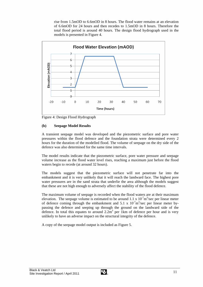
rise from 1.5mOD to 6.6mOD in 8 hours. The flood water remains at an elevation of 6.6mOD for 24 hours and then recedes to 1.5mOD in 8 hours. Therefore the total flood period is around 40 hours. The design flood hydrograph used in the models is presented in Figure 4.
Figure 4: Design Flood Hydrograph (b) Seepage Model Results
A transient seepage model was developed and the piezometric surface and pore water pressures within the flood defence and the foundation strata were determined every 2 hours for the duration of the modelled flood. The volume of seepage on the dry side of the defence was also determined for the same time intervals. The model results indicate that the piezometric surface, pore water pressure and seepage volume increase as the flood water level rises, reaching a maximum just before the flood waters begin to recede (at around 32 hours). The models suggest that the piezometric surface will not penetrate far into the embankment and it is very unlikely that it will reach the landward face. The highest pore water pressures are in the sand strata that underlie the area although the models suggest that these are not high enough to adversely affect the stability of the flood defence. The maximum volume of seepage is recorded when the flood waters are at their maximum elevation. The seepage volume is estimated to be around 1.1 x 10⁻⁷m3/sec per linear meter of defence coming through the embankment and 5.1 x 10⁻⁷m3/sec per linear meter by-passing the defence and seeping up through the ground on the landward side of the defence. In total this equates to around 2.2m3 per 1km of defence per hour and is very unlikely to have an adverse impact on the structural integrity of the defence. A copy of the seepage model output is included as Figure 5.

Black & Veatch Ltd Site Investigation Report / April 2011 12
Figure 5: Seepage model output at highest flood water level. Total head contours are marked in meters and seepage volumes in m3/second. Seepage through and immediately below the embankment may cause the development of localised soft spots at the landward toe. The seepage water can be controlled by constructing a drainage ditch around 5m from the landward toe of the embankment to collect the water and allow it to flow away in a controlled manner. The drainage ditch will need to be connected into the existing drainage network and the water collected must be able to flow or be pumped back into the Estuary. A number of land drains are also present at the site and some of these are likely to cross the line of the new flood defence embankment. These could represent a preferential flow path, possibly leading to excessive seepage. Therefore it will be necessary to remove or break the drainage network in the vicinity of the new defence during the development of the site. (c) Stability Model Results
The results of the stability models indicate that the flood defence will have the following minimum Factors of Safety (FoS) (Table 2). Table 2: Factor of Safety (Global and BS EN 1997) for Different Model Scenarios
Model Scenario Minimum Factor of Safety (Global)
Minimum Safety Factor recorded in accordance
with BS EN 1997* Long term case seaward facing
slope 1.47 1.17
Long term case seaward facing slope with flood waters at their
peak
2.01 1.50
Long term case seaward facing slope after the rapid drawdown of
flood waters
1.47 1.17
Short term case seaward facing slope
2.94 2.10
Long term case landward facing slope with flood waters at their
peak
1.49 1.18
* The minimum safety factor was also calculated in accordance with BS EN 1997 (EuroCode 7). Using this methodology, the geotechnical soil properties are factored in the analysis and so the target safety factor is 1.0. The embankment is most stable (the FoS is at its highest) when the flood water elevation is greatest and then decreases as the flood waters receded and the side slopes are exposed. This is a typical response to a flood situation. The flood waters do not penetrate far into the flood defence because the water retention time is short and the permeability is relatively low. The FoS is reduced as the flood waters recede and rapidly returns to its pre-flood condition.

Black & Veatch Ltd Site Investigation Report / April 2011 13
The stability model output with the lowest FoS for the long term drained and short term undrained cases are included as Figure 6 and Figure 7 respectively.
Figure 6: Long term embankment stability minimum FoS.
Figure 7: Short term embankment stability minimum FoS. The modelled FoS are adequate for the proposed flood defence embankment and, other than minor non-structural near surface failures, the defence would be expected to be stable in all of the cases modelled.

Black & Veatch Ltd Site Investigation Report / April 2011 14
Sensitivity analysis was undertaken by reducing various soil properties including the angle of shearing resistance in the embankment fill from 27° to 25° and underlying Warped Soil and Estuarine Alluvium from 26° to 25°. In this case the minimum global FoS recorded for the long term drained case is around 1.34 and the BS EN 1997 partial safety factor is 1.07. These are still adequate for the proposed flood defence embankment.
Black & Veatch Ltd Site Investigation Report / April 2011 15
6. MASS BALANCE CALCULATION
The following is a preliminary estimate of the volume of spoil created during construction and the volume of fill needed to complete the works. The preliminary mass balance calculation is an initial estimate and a more detailed understanding of spoil creation and re-use will be needed during the detailed design of the works. This will require a detailed understanding of the embankment alignment, the requirement for other earthworks, the relative proportion of different types of habitat and the ground levels needed to achieve these.
6.1 Spoil Produced During the Works
The topographic survey for the area suggests that the site is relatively level and that the typical ground elevation is around 2.5mAOD. It has been assumed that the site development will ultimately lead to the creation of large areas of salt marsh and it will not be necessary to carry out a site wide reduction in the ground elevation to create a mudflat area. Re-profiling of the ground may be needed in certain areas to aid tidal drainage of the site and encourage the development of tidal mudflat. Therefore, the volumes of spoil produced during the works are expected to be relatively small.
6.2 Fill Required During Embankment Construction
The development will require the construction of a new flood defence earth embankment at the northern boundary of the site. The new embankment will be constructed to allow for 100 years of sea level rise and therefore the crest elevation is predicted to be around 6.66mOD increasing to 7.33mOD for a 750m length of defence which is particularly subject to wave action. Therefore, including an allowance of around 200mm to 300mm for consolidation and settlement, the height of the embankment varies from around 4.5m to 5.0m. The length of the new embankment will depend on the area and shape of the site ultimately selected for development. However, at this stage it has been assumed that the new embankment is around 3.0km in length. The stability and seepage modelling suggests that a suitable factor of safely should be achieved if the embankment is constructed with a 4m wide crest and 1m vertical to 3m horizontal side slopes. The following fill requirement can be calculated (Table 3): Table 3: Volumes of Fill Required for Embankment Construction
Length (m) Height (m) Crest Width
(m) Slope
Gradient Volume of Fill
(m3) 2250 4.5 4.0 1V:3H 177187.5 750 5.0 4.0 1V:3H 71250.0
Total 3000 248,437.5 Therefore, around 250,000m3 of fill is likely to be required in the construction of the proposed flood defence embankment.
6.3 Source and Likely Volume of Fill on Site
The only likely on site source of fill is the Warped Soil and cohesive Estuarine Alluvium in the upper 1.5m of the soil profile. The topsoil is around 0.3m-0.4m thick and so the actual thickness of potential fill available is likely to be around 1.1m to 1.2m. These site

Black & Veatch Ltd Site Investigation Report / April 2011 16
won soils are likely to require significant drying prior to use as fill in embankment construction. The proposed site development area is around 100ha and the area containing cohesive Warped Soil appears to be predominately in the eastern third of the site. If it assumed that the cohesive soils are in an area of around 35ha (350,000m2) and assuming a cohesive soil thickness of 1.1m, the total volume of potential fill available may be around 385,000m3. Based on these assumptions, it seems likely that there is sufficient cohesive soil on site to construct the proposed embankments, although it may be very difficult to identify suitable soil by visual examination alone. It will also be necessary to reduce the moisture content of the Warped Soil and the cohesive Estuarine Alluvium to make it suitable for use as fill.
6.4 Topsoil
Topsoil, stripped to form the flood defence embankment foundation stratum or removed from borrow areas prior to excavation, should be re-used to cover the embankment or re-used elsewhere on site in the proposed site development works. It is also proposed that topsoil and salt marsh removed from the seaward side of the proposed breach is placed within the compensation site to encourage the development of salt marsh.
6.5 Surplus Spoil
Surplus spoil is waste and so it is important to minimise surplus spoil production. The mass balance calculation suggests that the proposed works at Cherry Cobb Sands are unlikely to produce surplus spoil and so waste spoil generation should be minimal.

Black & Veatch Ltd Site Investigation Report / April 2011 17
7. LAND CONTAMINATION
Land contamination is considered in the planning process. Potentially contaminated land needs to be identified and the risks associated with such land assessed. Planning Policy Statement 23 (PPS23) Planning and Pollution Control requires a precautionary approach to land contamination and planning permission can be refused if risks to receptors are deemed to be unacceptable. Part IIa of the Environmental Protection Act 1990 complements the planning process and provides a statutory regime for the identification of historically contaminated land. Again this is based on risk and it adopts the source-pathway-receptor approach to the identification of potentially significant linkages between contaminants and receptors. For a risk to exist there must be a source of contamination, a receptor capable of being affected by the contamination and a pathway between the two. This is often referred to as a pollutant linkage. DEFRA and the Environment Agency guidance, Model Procedures for the Management of Land Contamination (CLR11) emphasises the need for a tiered approach to risk assessment. An initial preliminary qualitative risk assessment is normally carried out and, if needed, this will be followed by a generic quantitative risk assessment and finally a detailed quantitative risk assessment. The preliminary qualitative risk assessment carried out as part of the Desk Study (BV, 2010a) identified three potential pollution linkages that were assessed to be either unacceptable of undesirable. For ease of reference, the appropriate section of the risk assessment is reproduced below as Table 4. Site investigations were designed that sought to provide additional site specific data to allow these risks to be assessed in more detail and the following discussion summarises the results of these investigations.

Black & Veatch Ltd Site Investigation Report / April 2011 18
Probability of Occurrence: VL= Improbable: unlikely to occur L= Remote: unlikely but possible M= Occasional: possible at some time H= Probable: likely to occur several times VH = Frequent: likely to occur many times
Severity: 1 = Negligible: No impact likely 2 = Marginal: Minor environmental impact, no lasting damage 3 = Serious: Environmental impact, damage in short term. Minor illness 4 = Critical: Major environmental impact, damage medium/long term. Serious illness 5 = Catastrophic: Permanent environmental damage. Serious illness or death
UA = Unacceptable UD = Undesirable A = Acceptable N = Negligible
Assessed risk:
Severity 1 2 3 4 5
Pro
babi
lity VL N N A A UD
L N A A UD UA M A A UD UA UA H A UD UD UA UA
VH UD UD UA UA UA
Table 4: Qualitative Risk Assessment for Complete Potential Pollution Linkages
1 2 3 4 5 6 7 8 Source Pollutant Receptor Potential Pathway Consequence Probability of
Occurrence Severity Assessed
Risk World War II
Decoy Site UXO Oils
Site construction workers
Exposure of UXO during construction works leading to explosion and severe injury or death.
Inhalation of dust or dermal contact with polluted soil or groundwater during site
construction works
Harm to human receptors L 5 UA
Historic Landfill at
Cherry Cobb Sands
Organic and inorganic pollutants
Site construction workers
Inhalation of dust or dermal contact with polluted soil or groundwater during site
construction works
Harm to human receptors M 3 UD
Historic Landfill at
Cherry Cobb Sands
Organic and inorganic pollutants
Surface Waters in the Humber Estuary
Polluted soils used as fill in embankment construction. Contaminants leached by rainfall
infiltration which seep into the Estuary or ditches leading into the Estuary
Pollution of surface water
M 3 UD

Black & Veatch Ltd Site Investigation Report / April 2011 19
7.1 Chemical Analysis of Soils at Cherry Cobb Sands
Fourteen soil samples were collected from a number of trial pits (TP) at the site and tested in the laboratory for a range of potential pollutants including metals, total petroleum hydrocarbons (TPH), poly aromatic hydrocarbons (PAH), volatile and semi volatile organic compounds (VOC, SVOC), insecticides, asbestos and waste acceptance criteria (WAC). TP11 and TP12 were positioned to identify the location of the historic landfill identified as Land West of Cherry Cobb Sands Road on the Environment Agency website (EA, 2011). Soils in TP11 and TP12 were impacted by landfill materials and 6 of the samples were collected from these TP at depths of 0.2m to 1.9m below ground level (bgl). The remaining 8 soil samples were collected from 8 TP at other locations at the site at depths of between ground level and 0.3m bgl. The long term risks to human health can initially be assessed by comparing the concentrations of contaminants in soils to generic tier 1 screening criteria. Tier 1 screening values represent a concentration of a particular contaminant below which there is considered to be a very low risk to human health. However, soil contaminant concentrations that exceed the screening value require additional assessment to understand the potential risks in more detail and do not necessarily mean that a soil is contaminated. Additional assessment, if needed, may include a detailed quantitative risk assessment (DQRA). However, in this case there are no published screening criteria for the proposed site land use as a compensation site and so comparison has been made to published screening criteria for a residential and allotment land use. The screening values used are UK Soil Guideline Values (SGV) (EA, 2009 and DEFRA/EA, 2002) and generic assessment criteria (GAC), produced using the CLEA methodology and published by LQM/CIEH (LQM/CIEH, 2009) and CL:AIRE (CL:AIRE 2010). These screening criteria are likely to be very conservative for this site development and, if a more detailed site risk assessment is needed, site specific screening criteria should be developed. A number of initial conclusions can be drawn from the assessment.
(a) Non Landfill Impacted Soils
The non landfill impacted soils at the site do not contain visual or olfactory evidence of contamination and do not contain contaminants in concentrations that exceed the screening criteria selected. Therefore, these soils are very unlikely to cause harm to human receptors. The concentrations of potential contaminants in the soils are low and leachate forming as water passes through the soils would not be expected to adversely affect controlled water (surface or groundwater) receptors in the area. Therefore, based on the data currently available, the non landfill impacted soils are likely to be chemically suitable for re-use on site. (b) Landfill Impacted Soils
The site engineer described the landfill impacted soils as containing a variety of anthropogenic materials including possible asbestos (sheet fragments and wool) and having a “very strong (overwhelming) VOC and hydrocarbon odour”. This suggests that these soils contain significant concentrations of volatile contaminants and could present a risk of both acute and long term harm to human receptors.

Black & Veatch Ltd Site Investigation Report / April 2011 20
The chemical data also indicates that the soils contain a number of contaminants in concentrations that exceed the screening criteria selected. These are listed below (Table 5).
Table 5: Contaminants that Exceed the Screening Criteria Selected
Potential Contaminant
Maximum Concentration
Recorded (mg/kg)
Number of Samples that
exceed the screening criteria
TP No. Depth (m)
Conservative Screening Criteria
(mg/kg)
Cadmium 1.9 1 of 10 TP11 0.2m 2009 EA Allotment SGV 1.8
Copper 1000 1 of 10 TP11 0.2m LQM Allotment GAC 524
Lead 1000 1 of 10 TP11 0.2m 2002 EA Residential SGV 450
(commercial/industrial SGV 750)
Zinc 1900 2 of 10 TP11 0.2m LQM Allotment GAC 618
TPH Aliphatic C8-C10
73 1 of 5 TP11 1.5m LQM Residential GAC 19-110
TPH Aliphatic C10-C12
580 1 of 5 TP11 1.5m LQM Residential GAC 93-540
TPH Aromatic C8-C10
170 1 of 5 TP11 1.5m LQM Allotment GAC 8.6-51
TPH Aromatic C10-C12
140 1 of 5 TP11 1.5m LQM Allotment GAC 13-74
TPH Aromatic C12-C16
430 1 of 5 TP11 1.5m LQM Allotment GAC 23-130
TPH Aromatic C16-C21
560 1 of 5 TP11 1.5m LQM Allotment GAC 46-260
TPH Aromatic C21-C35
1700 1 of 5 TP11 1.5m LQM Allotment GAC 370-1600
Benzo(a)Pyrene 1 1 of 9 TP11 0.5m LQM Residential GAC 0.83-1.0
Benzene 0.14 1 of 5 TP11 1.5m 2009 EA Allotment SGV 0.02-0.07
Asbestos chrysotile 1 of 4 TP12 1.2m No SGV/GAC
The elevated contaminants recorded tend to be in a limited number of samples from TP11 and this probably reflects the small number of samples tested and the variability of the landfill material. However, in general the concentrations of contaminants recorded are not as high as might be expected from the site descriptions. This is probably because many of the pollutants observed during the site investigation are likely to be volatile and these pollutants volatilise rapidly when exposed to air. Therefore, the concentrations recorded in the laboratory analyses are lower than expected and the results may not accurately reflect the ground conditions. As a result of this it is essential that emphasis is placed on the evidence of contamination recorded during the site investigations. It should also be noted that the elevated metal and PAH contaminants are recorded at a depth of 0.2 m-0.5m and these soils may be part of a capping layer. The hydrocarbon impacted soils appear to be at a greater depth and the maximum TPH concentration recorded was 10,000mg/kg (TP11 1.5m). Therefore, given the site engineers descriptions of the landfill impacted soils, the visual and olfactory evidence of hydrocarbon and VOC pollution and the chemical data, it seems unlikely that these soils would be chemically suitable for use as fill at or near the land surface in the proposed works.

Black & Veatch Ltd Site Investigation Report / April 2011 21
It is recommended that a 50m no excavation zone is placed around the historic landfill and that the landfill impacted soils are not excavated or disturbed during the site development. However, if it is necessary to disturb or re-use these soils then a more detailed assessment of the acute and long term risk to both human and controlled water receptors would be required. This would probably require further site investigations to delineate the landfill boundaries and to provide additional chemical data, allowing the landfill impacted soils to be more accurately characterised. Any additional site investigations of this type would require careful planning to ensure that potential acute risks to site operatives were minimised. If the hydrocarbon impacted soils within the landfill are excavated and require off-site disposal as waste, then they are likely to be classed as hazardous waste (NB further data would be required to fully characterise these soils). However, the organic content of these soils is currently too high for disposal to a hazardous waste landfill and appropriate pre-treatment would be needed prior to disposal. It should also be noted that there are a number of other filled drainage channels shown on LIDAR images (Figure 8) of the site. These can also be seen on various aerial photographs of the area, including the 1947 aerial photograph in Appendix V of the Delta Simons Factual Report (Delta Simons, 2011) which shows 7 main historic channels within the 110ha site boundary. None of these historic drainage channels are recorded on the EA Website as landfills, although it is mentioned in the Hickling Gray Associates pre-application consultation response that former creeks at the site may have been in-filled with industrial and commercial waste (Hickling Gray, 2011). Additional site investigations are required prior to the commencement of the detailed design, to evaluate these historic channels in more detail. (c) Unexploded Ordnance
The foreshore adjacent to the north western boundary of the site was used as a World War II decoy and, as a result, the qualitative risk assessment undertaken during the Desk Study (BV, 2010a) identified the risk of encountering UXO as unacceptable. Therefore, appropriate protective measures were undertaken during the site investigation and this involved the use of a magnetometer at the location of each of the CPT and BH positions and a radar survey at each of the TP locations to ensure that no metallic objects were present. No magnetic anomalies were identified although it should be noted that the UXO investigations were focused at the locations of the site investigation positions and are not necessarily representative of the entire site. However, the potential remains for encountering UXO during the development of the site and, in particular, the excavation of large borrow pits. Therefore, it is recommended that a detailed unexploded ordnance survey and risk assessment is carried out prior to the commencement of detailed site development design works.

Black & Veatch Ltd Site Investigation Report / April 2011 22
8. WASTE
Waste is defined in Article 1(a) of the European Waste Framework Directive as, “any substance or object….which the holder discards or intends or is required to discard”. Waste is carefully controlled in the UK and the costs associated with the management and disposal of waste spoil can be high. Therefore, wherever possible, it is important to ensure that spoil created during construction work is not classed as waste. Article 2 of the Waste Framework Directive 2008/98/EC, which was fully implemented in the UK in December 2010, indicates that “uncontaminated soil and other naturally occurring material excavated in the course of construction activities where it is certain that the material will be used for the purposes of construction in its natural state on the site from which it was excavated” is excluded from the Directive and would therefore not normally be classed as waste. Therefore, it is unlikely that the soils excavated for use as fill in embankment construction at Cherry Cobb Sands would be classed as waste. Current industry best practice regarding earthworks and the generation of waste is provided in the CL:AIRE guidance document, The Definition of Waste: Development Industry Code of Practice (CL:AIRE, 2008). This states that spoil produced during construction works would not normally be classed as waste providing that the following criteria apply:
There must be a re-use and the re-use must be certain. Only the quantity necessary for the specified works can be used. The soil is chemically and physically suitable for re-use without treatment.
The CL:AIRE CoP provides an accepted methodology for proving that soil excavated on site is certain to be re-used and does not require treatment. NB soil stabilisation using lime or cement is not considered by the Environment Agency to be a treatment operation and does not cause the stabilised soil to become a waste (EA, 2008). Therefore, whilst not compulsory, it is recommended that the works are designed and managed in accordance with the CL:AIRE CoP. The preliminary mass balance calculation in Section 6 of this report suggests that the works are unlikely to create surplus spoil. However, the soils that are impacted by the historic Cherry Cobb Sands landfill at the western end of the site, and in particular those that are polluted with hydrocarbon, are unlikely to be suitable for re-use as fill without treatment and if excavated, are likely to be waste. Further investigations of the other historic channels at the site are required to ensure that these soils are suitable for re-use. Therefore, it is recommended that the works are designed so that they do not cause the soils impacted by landfill to be excavated.

Black & Veatch Ltd Site Investigation Report / April 2011 23
9. CONCLUSIONS AND RECOMMENDATIONS
9.1 Geology and Hydrogeology
The ground conditions at the site are likely to comprise topsoil over around 1.5m of Warped Soil comprising (soft to) firm, sandy clay with occasional lenses of sand and sandy silt over Estuarine Alluvium. The cohesive (sandy clay) Warped Soil appears to be toward the eastern end of the site and the Warped Soil across the remainder of the site appears to be composed of non-cohesive (sandy silt) soils. The Estuarine Alluvium is likely to be more than 15m thick and comprises fine grained silty sands and sandy silts interbedded with organic silty clays and occasional layers of peat. The non-cohesive sands and silts are the dominant soil types and are generally up to 10m thick whilst the cohesive soils are somewhat thinner and are typically less than 2-3m thick. The Estuarine Alluvium is likely to be underlain by Glacial Deposits comprising Till (stiff gravelly clay) and Glacial Sands and Gravels. The groundwater table is likely to be at a depth of around 1.5m bgl across much of the site and may vary in response to changes in the tide cycle and rainfall. The near surface soils at the site are classed as unproductive strata and are unlikely to be used for groundwater supply.
9.2 Engineering Issues
(a) Bearing Capacity
The Warped Soil forming the upper 1.5m of the soil profile has dried naturally over time forming a crust. As a result of the drying the undrained shear strength and bearing capacity of the Warped Soil is higher than the underlying soils. Therefore, the Warped Soil is likely to provide a suitable foundation stratum for an embankment with a maximum height of 5.0m. To ensure the maximum bearing capacity is achieved, it is essential that the full thickness of Warped Soil is retained and so any stripping of soil to form a foundation stratum should be minimised. Any localised soft spots in the foundation soils should be removed and replaced with suitably compacted fill. If large soft areas are encountered then it may be necessary to incorporate a ground strengthening geo-textile at the foundation level or to treat the affected soils with lime or cement to increase the shear strength. (b) Settlement
The near surface Warped Soil and Estuarine Alluvium will form the foundation strata for the proposed embankment. In most parts of the site the majority of the Estuarine Alluvium is composed of silts and sands and will consolidate rapidly under load as the new embankment is constructed. These granular soils are unlikely to cause significant long term consolidation and settlement of the embankment and its foundation. In certain areas the Warped Soil and strata within the Estuarine Alluvium are cohesive and are likely to consolidate under the load imposed by the new embankment. This will lead to total and differential settlement of the embankment and its foundation and calculations predict that total settlement of the crest could be around 200mm to 300mm. Therefore the embankment design should include an allowance for the predicted levels of settlement.

Black & Veatch Ltd Site Investigation Report / April 2011 24
(c) Seepage
A transient seepage model was developed to evaluate the volume of seepage on the dry side of the defence and pore water pressures within the embankment during normal operation and as the result of a major flood event. The models indicate that the piezometric surface will not penetrate far into the embankment and it is very unlikely that it will reach the landward face. The highest pore water pressures are in the sand strata that underlie the area although these are not expected to adversely affect the stability of the defence. The maximum volume of seepage resulting from the flood event is estimated to be around 6.2 x 10⁻⁷m3/sec per linear meter of defence (or around 2.2m3 per 1km of defence per hour). Seepage at this rate is very unlikely to have an adverse impact on the structural integrity of the defence. Any seepage that does occur can be controlled by constructing a drainage ditch around 5m from the landward toe to collect water and allow it to flow away from the embankment in a controlled manner. The drainage ditch will need to be connected to the existing drainage network and the water collected must be able to flow or be pumped back into the Estuary. It will also be necessary to remove or break the existing land drainage network in the vicinity of the new defence to ensure that it does not act as a preferential flow path and lead to excessive seepage. (d) Stability
Modelling was also undertaken to evaluate embankment stability during normal operation and a major flood event, including a rapid drawdown of flood waters. The modelling indicates that an embankment constructed with 1V to 3H side slopes and a crest width of 4m would have an adequate factor of safety against failure in all of the cases modelled. However, relatively minor, near surface failures may occur in certain conditions and these should be repaired rapidly to ensure the continued operation of the defence. (e) Site Won Fill
The only likely on site source of cohesive soil is the Warped Soil in the upper 1.5m of the soil profile. Other cohesive soils at the site are below the water table and likely to be too wet for use as fill or too deep to make excavation economically viable. The site investigation data suggests that the Warped Soil is cohesive in certain areas and non-cohesive in other parts of the site. Cohesive Warped Soil tends to be in the eastern third of the site and the Warped Soil across the remainder of the site appears to be non-cohesive (sandy silt). The non-cohesive soils are unlikely to be suitable for use as fill in embankment construction. Additional site investigations are recommended to confirm the location and extent of the cohesive Warped Soil. The cohesive and non-cohesive Warped Soils may look similar in excavations and it is likely to be very difficult to identify the suitable cohesive soils by visual examination alone, making the selection of fill problematic. The cohesive Warped Soil typically comprises silty clays with a natural moisture content of around 30%. However, the compaction tests suggest that the maximum dry density would be achieved at an optimum moisture content of around 20%. Therefore, these soils are too wet to use as embankment fill without drying to reduce the moisture content.

Black & Veatch Ltd Site Investigation Report / April 2011 25
The effectiveness of air drying is dependent on the time available and weather conditions and, given the reduction in moisture content required and the short construction period, is unlikely to provide certainty in the provision of a suitable fill. The addition of lime chemically modifies the soil and a moisture content reduction of around 8% to 10% can probably be achieved. However, trials and discussions with specialist contractors are recommended to determine the amount of lime required and the impact that the addition of lime would have on the properties of the compacted soil. Groundwater is likely to be encountered in borrow excavations that are greater than around 1.5m and this will reduce the stability of the excavation side wall, potentially leading to collapse. The soils beneath the base of the borrow excavations are likely to be soft or loose and therefore appropriate precautions are required to ensure that excavation plant do not disturb the foundation and become bogged. (f) Off Site Sources of Fill
The site won soils may prove to be too silty to use as fill and so it may be necessary to use imported soil. Glacial Till is likely to be suitable for use as embankment fill and is exposed at the ground surface at a number of locations around 5km to the north of the site. The Glacial Till could be used to construct the entire embankment or, to minimise the volumes of imported fill required, as a clay core within an embankment primarily constructed from site won soil. (g) Trial Embankment
A trial embankment would assist in the development of a suitable and cost effective construction methodology prior to the commencement of the main site development. They are particularly useful in areas where there are concerns regarding the quality of site won fill and would enable the site won soil at Cherry Cobb Sands to be fully evaluated prior to the commencement of construction. A trial embankment has a number of advantages including providing certainty in the construction methodology, minimising potential construction delays and ensuring that the embankment can be completed in accordance with the programme. Therefore, consideration should be given to the construction of a trial embankment prior to the commencement of the main site development. (h) Breaching the Existing Defence
The existing defence should not be breached until the new defence is fully operational and it is normally recommended that the breach does not occur until the grass cover has had time to develop. However, it may be possible to breach the defence prior to the development of grass cover providing that suitable erosion protection is incorporated into the design and that any damage is repaired rapidly.
9.3 Mass Balance Calculations
Preliminary mass balance calculations have been undertaken to evaluate both the volume of soil created during the works and the volume of fill required to complete the works. More detailed mass balance calculations should be undertaken as the detailed design of the site is developed. It is assumed that the site will develop into an area of salt marsh and that a site wide reduction in ground elevation will not be required. Profiling of the ground may be needed in certain areas to aid tidal drainage of the site and encourage the development of tidal

Black & Veatch Ltd Site Investigation Report / April 2011 26
mudflat but in general the works are expected to create a relatively limited volume of spoil. The development will require the construction of a new flood defence earth embankment at the northern boundary of the site. The embankment will be around 4.5m to 5.0m high and 3km long and will require around 250,000m3 of fill which is expected to be primarily obtained from on site borrow excavations. Therefore, the construction of the flood defence is likely to require all of the spoil produced during the works and so the development is unlikely to create surplus spoil.
9.4 Land Contamination
The majority of the soils at the site do not contain visual or olfactory evidence of contamination and do not contain contaminants in elevated concentrations. Therefore, these soils are unlikely to cause harm to human or environmental receptors and are likely to be chemically suitable for re-use on site. However, the site investigations encountered landfill impacted soils at the western end of the site and these are associated with an historic landfill recorded on the Environment Agency website (EA, 2011) as Land West of Cherry Cobb Sands Road. The landfill impacted soils contain a variety of anthropogenic materials including possible asbestos (sheet fragments and wool) and have a “very strong (overwhelming) VOC and hydrocarbon odour” (Delta Simons, 2011). The chemical data also indicate that the soils contain a number of metal and hydrocarbon contaminants in concentrations that exceed the screening criteria selected. The maximum TPH concentration recorded was 10,000mg/kg. However, in general the concentrations of contaminants recorded are not as high as might be expected from the site descriptions and this is probably because many of the pollutants recorded during the site investigation are volatile and react rapidly when exposed to air. Therefore, based on the visual and olfactory evidence of hydrocarbon and VOC pollution and the site chemical data, it seems unlikely that these soils would be chemically suitable for use as fill in the proposed works. If the site development requires the landfill impacted soils to be disturbed or re-used, then a more detailed assessment of the acute and long term risk to both human and controlled water receptors would be required. There are also likely to be other filled historic drainage channels at the site and, whilst none are recorded on the EA website as landfills (EA, 2011), there is limited anecdotal evidence to suggest that some of these channels may have been filled with potentially polluting materials and waste. Additional site investigations are required to evaluate these areas in more detail.
9.5 Waste
Surplus soil and soil that is unsuitable for re-use on site with or without treatment is waste and would need to be managed accordingly. The mass balance calculations in this report indicate that the works are unlikely to produce surplus soil. It is also recommended that the landfill impacted soils, which are likely to be chemically unsuitable for re-use on site, are not excavated during the works. Therefore, the site development is unlikely to create significant volumes of surplus or chemically unsuitable soil. It is unlikely that any natural, unpolluted soils excavated at the site and re-used in embankment construction would be classed as waste, providing that their re-use is certain. The CL:AIRE CoP (CL:AIRE, 2008) provides a methodology for proving that soil
Black & Veatch Ltd Site Investigation Report / April 2011 27
excavated on site is certain to be re-used and whilst not compulsory, it is recommended that the works are designed and managed in accordance with this guidance.
9.6 Unexploded Ordnance
The foreshore adjacent to Cherry Cobb Sands was used as a decoy site during World War II and may have been bombed. Localised UXO investigations were undertaken during the site investigation at investigation positions to ensure that these works could be undertaken safely. Whilst no anomalies were identified, the risks of encountering unexploded ordnance (UXO) in borrow excavations and other site development works remains. Therefore, it is recommended that a detailed unexploded ordnance survey and risk assessment is carried out prior to the commencement of detailed design works.
Black & Veatch Ltd Site Investigation Report / April 2011 28
10. REFERENCES
BV, 2010. Able Marine Energy Park. Preliminary Identification of Alternative Sites for Habitat Compensation. Black & Veatch. September 2010. BV, 2010a. Able Marine Energy Park. Summary Desk Study and Site Investigation Design Report. Black & Veatch. December 2010. CL:AIRE, 2008. The Definition of Waste: Development Industry Code of Practice. Contaminated Land: Applications in Real Environments (CL:AIRE). September 2008. CL:AIRE, 2010. Soil Generic Assessment Criteria for Human Health Risk Assessment. CL:AIRE, 2010. DEFRA/EA, 2002. DEFRA and Environment Agency. Soil Guideline Values for Lead Contamination. R&D Publication SGV 10. 2002. CLEA. Delta Simons, 2011. Factual Report on Ground Investigation at Cherry Cobb Sands. March 2011. Directive 2008/98/EC on waste and repealing certain Directives. 22/11/2008 EA, 2008. Definition of Waste and Land Development. Frequently Asked Questions. Technical Questions. Environment Agency. Sept 2008. EA, 2009. Environment Agency. Soil Guideline Value Reports (Various). 2009. EA, 2011 Environment Agency Website. What’s in your backyard. Accessed March 2011. http://maps.environment-agency.gov.uk/wiyby/wiybyController?ep=maptopics&lang=e Hickling Gray, 2011. Hickling Gray Associates. Pre-application consultation response on behalf of Mr. S Kirkwood and Mr A.P. Leake. 17 March 2011. LQM/CIEH, 2009. Generic Assessment Criteria for Human Health Risk Assessment. Land Quality Management Ltd and CIEH. 2009.

KEY
A 28/03/2011 Preliminary Issue AJS LVI
Rev Date Comments Drw Chk App
Project:
Client:
Title:
ABLE UK Ltd
PRELIMINARYScale:
@A3
Drawn Checked Approved
Date 28/03/2011 28/03/2011
Drawing No. Revision:A
0 200 400 600 800 1,000
Metres
CHERRY COBB SANDS COMPENSATION SITE
FIGURE 1: SITE LOCATION PLAN
AJS LVI
121726-7000-0100
1:12,500
R:\Projects\121726_Humber_Compensation_EIA_Strategy\8_Workspaces\2_issue_Maps\121726_7000_0100_SI_LOCATION_PLAN.MXD AJS 29/03/2011
Reproduced from the Ordnance Survey Mapping by Black & Veatch with the permission of the Controller of Her Majesty's Stationery Office © Crown Copyright.
Unauthorised reproduction infringes Crown Copyright and may lead to prosecution or civil proceedings. Licence No. 0100031673
Legend
Study Area
Proposed Defence Re-Alignment

KEY
A 28/03/2011 Preliminary Issue AJS LVI
Rev Date Comments Drw Chk App
Project:
Client:
Title:
ABLE UK Ltd
PRELIMINARYScale:
@A3
Drawn Checked Approved
Date 28/03/2011 28/03/2011
Drawing No. Revision:A
"
"
!(
"
"
"
!(
"
"
"
"
"
<
_
_
_
_
_
_
_
_
_
_
_
_
é
é
é
é
é
é
é
é
é
é
éé
é
é
Main area ofWorld War IIdecoy site
Area of historiclandfill
TP14
TP13
TP12TP11
TP10
TP09
TP08
TP07
TP06
TP05
TP04
TP03
TP02
TP01
BH01
CPT12
CPT11
CPT10
CPT09
CPT07
CPT06
CPT05
CPT04
CPT03
CPT02
CPT01
CPT08
0 200 400 600 800 1,000
Metres
CHERRY COBB SANDS COMPENSATION SITE
FIGURE 2: SITE INVESTIGATION POSITIONS
AJS LVI
121726-7000-0101
1:12,500
R:\Projects\121726_Humber_Compensation_EIA_Strategy\8_Workspaces\2_Issue_Maps\121726_7000_0101_SI_POSITIONS.mxd AJS 05/04/2011
Reproduced from the Ordnance Survey Mapping by Black & Veatch with the permission of the Controller of Her Majesty's Stationery Office © Crown Copyright.
Unauthorised reproduction infringes Crown Copyright and may lead to prosecution or civil proceedings. Licence No. 0100031673
Legend
Study Area
< Borehole
_ Cone Penetration Test
" Probable Cohesive Soils from 0.3m to 1.2m
" Probable Non-cohesive Soils from 0.3m to 1.2m
!( Soil Type from 0.3m to 1.2m is Uncertian
é Trial Pit
Proposed Defence Re-Alignment

KEY
A 28/03/11 Preliminary Issue AJS LVI xxx
Rev Date Comments Drw Chk App
Project:
Client:
Title:
ABLE UK Ltd
PRELIMINARYScale:
@A3
Drawn Checked Approved
Date 28/03/2011 28/03/2011 dd/mm/yyyy
Drawing No. Revision:A
0 100 200 300 400 500
Metres
0 100 200 300 400 500
Metres
CHERRY COBB SANDS COMPENSATION SITE
FIGURE 8:HISTORIC DRAIN CHANNELS
AJS LVI
121726-7000-0103
R:\P
roje
cts\
12
172
6_
Hu
mb
er_
Co
mp
en
satio
n_
EIA
_Str
ate
gy\
8_W
orks
pa
ces\
2_
Issu
e_
Ma
ps\
12
17
26
_70
00
_H
isto
ric_
Dra
in_
Lo
catio
ns.
mxd
A
JS
28
/03
/20
11
Legend
Topography (m AOD)7
-2-101
23456
Study Area Boundary
LiDAR Image Aerial Photograph