*Abdulqadir Aziz Singapore Wala 1, Eddie Yin-Kwee Ng 2 · rotor modeling in computational fluid...
18
The 2012 World Congress on Advances in Civil, Environmental, and Materials Research (ACEM’ 12) Seoul, Korea, August 26-30, 2012 1 Undergraduate Student 2 Professor Actuator disc modeling based on aerodynamic data extraction from direct rotor modeling of the NREL Phase VI turbine *Abdulqadir Aziz Singapore Wala 1 , Eddie Yin-Kwee Ng 2 1,2 School of Mechanical and Aerospace Engineering, 50 Nanyang Ave., Nanyang Technological University, Singapore 2 [email protected] ABSTRACT Traditional Blade Element Momentum (BEM) methods based on 2-dimensional data are unable to accurately predict blade forces and thus are unreliable when used in actuator discs to predict wind turbine wake profiles. This can be circumvented by extracting relevant force and velocity data from direct modeling simulations or experiments, which are almost certainly used in the design process of a wind turbine. Methods developed by Bak et al to extract cross-sectional aerodynamic data from wind turbines (Bak, Fuglsang, Sorensen, Madsen, Shen, & Sorensen, 1999), included one based on an inverse BEM method, by using blade force data to find the axial and rotational induction factors of the blade element, and an actuator disc-based method, which used the exact pressure drop for each specific wind speed to create a model of pressure drop against local velocities. The present work will thus investigate the accuracy of actuator disc models based on direct rotor modeling data, by creating actuator discs through extraction of the induction factors using the methods described earlier, for the NREL Phase VI rotor. The wake parameters from these models will then be compared with traditional BEM-based actuator discs and a direct rotor model simulation. The two present methods used were found to possess similarly high accuracies in wake prediction in comparison to the direct rotor model, and displayed the ineffectiveness of an actuator disc model based on a traditional BEM algorithm using 2-dimensional airfoil data. It is thus proven that extraction of aerodynamic force data from direct modeling simulations or experiments can be done in a manner useful for the prediction of the performance of a wind farm. 1. INTRODUCTION Wind farms often operate at an efficiency lower than that of a single wind turbine, due to the fact that downstream turbines operate within the wakes of upstream ones. For example, (Neustadter & Spera, 1985) found that the power output for three turbines, each separated by 7 rotor diameters was reduced by 10%. Another problem inherent in wind farms is the
Transcript of *Abdulqadir Aziz Singapore Wala 1, Eddie Yin-Kwee Ng 2 · rotor modeling in computational fluid...

The 2012 World Congress on Advances in Civil, Environmental, and Materials Research (ACEM’ 12)Seoul, Korea, August 26-30, 2012
1Undergraduate Student 2Professor
Actuator disc modeling based on aerodynamic data extraction from direct rotor modeling of the NREL Phase VI turbine
*Abdulqadir Aziz Singapore Wala1, Eddie Yin-Kwee Ng2 1,2 School of Mechanical and Aerospace Engineering, 50 Nanyang Ave., Nanyang
Technological University, Singapore
ABSTRACT
Traditional Blade Element Momentum (BEM) methods based on 2-dimensional data are unable to accurately predict blade forces and thus are unreliable when used in actuator discs to predict wind turbine wake profiles. This can be circumvented by extracting relevant force and velocity data from direct modeling simulations or experiments, which are almost certainly used in the design process of a wind turbine.
Methods developed by Bak et al to extract cross-sectional aerodynamic data from wind turbines (Bak, Fuglsang, Sorensen, Madsen, Shen, & Sorensen, 1999), included one based on an inverse BEM method, by using blade force data to find the axial and rotational induction factors of the blade element, and an actuator disc-based method, which used the exact pressure drop for each specific wind speed to create a model of pressure drop against local velocities.
The present work will thus investigate the accuracy of actuator disc models based on direct rotor modeling data, by creating actuator discs through extraction of the induction factors using the methods described earlier, for the NREL Phase VI rotor. The wake parameters from these models will then be compared with traditional BEM-based actuator discs and a direct rotor model simulation. The two present methods used were found to possess similarly high accuracies in wake prediction in comparison to the direct rotor model, and displayed the ineffectiveness of an actuator disc model based on a traditional BEM algorithm using 2-dimensional airfoil data. It is thus proven that extraction of aerodynamic force data from direct modeling simulations or experiments can be done in a manner useful for the prediction of the performance of a wind farm.
1. INTRODUCTION
Wind farms often operate at an efficiency lower than that of a single wind turbine, due to the fact that downstream turbines operate within the wakes of upstream ones. For example, (Neustadter & Spera, 1985) found that the power output for three turbines, each separated by 7 rotor diameters was reduced by 10%. Another problem inherent in wind farms is the

decrease in lifespan of the rotors due to an increase in turbulence intensity in the wake. (Sanderse, Aerodynamics of Wind Turbine Wakes, 2009)
Effective computational aerodynamic simulation of a wind turbine, and by extension, a wind farm, is an elusive goal for many aerodynamicists. Of particular interest from computational simulations of wind turbines are the aerodynamics of the wakes. Three particular tasks were listed by(Sanderse, Aerodynamics of Wind Turbine Wakes, 2009) with regard to the simulation of wind turbine wakes:
1. Calculating rotor performance and wind farm efficiency, requiring time-averaged velocity profiles behind the turbines,
2. Calculating the blade loading of the turbines in the wakes of other turbines and fluctuations in electrical energy output, requiring turbulence fluctuations and intensity of the wake,
3. And calculating wake meandering, requiring large atmospheric eddies being taken into account.
However, there are inherent difficulties associated with computations of wind farms, including high computational costs due to the turbulent nature of the wind turbine wakes as well as the rotation of the rotor, resulting in difficulties creating a suitable computational mesh. (Sanderse, Aerodynamics of Wind Turbine Wakes, 2009)
To reduce the computational requirements of simulating wind turbines, several models, generally classified as generalized actuator disk models, have been created to accurately simulate the wind turbine, or the aerodynamic or aeroelastic effects of the wind turbine, while keeping computational costs low. In these models, the aerodynamic properties of the wind turbine are traditionally derived using momentum theory. While momentum theory can be used as part of an initial design stage of wind turbines, it is not highly accurate, resulting in a flawed actuator disc design to begin with.
However, the design process of modern wind turbines involves experiments and direct rotor modeling in computational fluid dynamics (CFD). These produce highly accurate and reliable results, from which useful data can be extracted and used in the planning and simulation process of wind farms employing these turbines. Bak et al used several methods to extract this data from direct rotor modeling simulations. (Bak, Fuglsang, Sorensen, Madsen, Shen, & Sorensen, Airfoil Characteristics for Wind Turbines, 1999). These included an actuator disc-based as well as an inverse BEM-based approach. The results of these were found to be in close agreement and simple to obtain.
Of the generalized actuator disc models, it is still found that only the actuator disc model allows for a simulation of a wind farm since the others are still too computationally demanding (Sanderse, van der Pijl, & Koren, Review of CFD for wind-turbine wake aerodynamics, 2011).
It shall thus be the purpose of this research to develop a methodology through which accurate actuator disc models can be generated using aerodynamic data extracted from direct
modeling of wind turbines, then comparing this methodology to conventional momentum theory-based actuator disc models. The present study will only simulate axial flows, with no rotational component added to the ADMs.
2. COMPUTATIONAL METHODOLOGY
The simulations were run on ANSYS Fluent 6.3.26. Fluent is an Eulerian, finite-volumes based CFD software. Fluent comes packaged with the grid generation software, Gambit, which was used to model the computational meshes for this project.
2.1 Direct rotor modeling
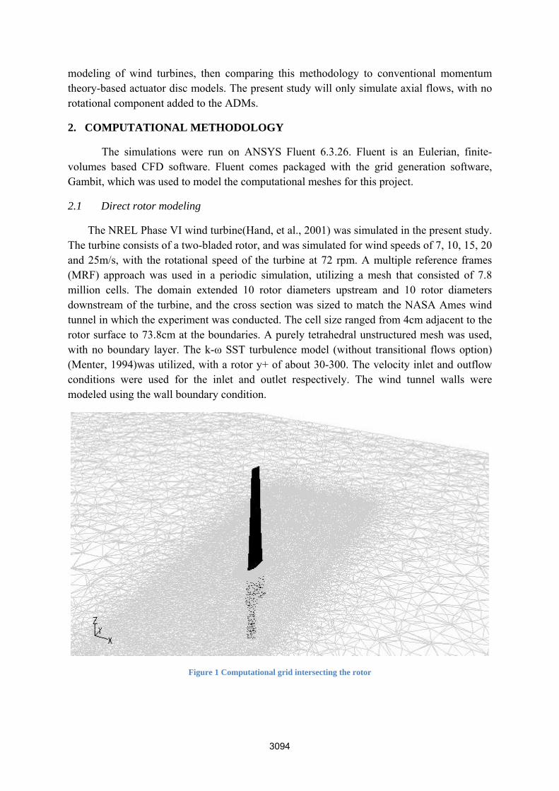
The NREL Phase VI wind turbine(Hand, et al., 2001) was simulated in the present study. The turbine consists of a two-bladed rotor, and was simulated for wind speeds of 7, 10, 15, 20 and 25m/s, with the rotational speed of the turbine at 72 rpm. A multiple reference frames (MRF) approach was used in a periodic simulation, utilizing a mesh that consisted of 7.8 million cells. The domain extended 10 rotor diameters upstream and 10 rotor diameters downstream of the turbine, and the cross section was sized to match the NASA Ames wind tunnel in which the experiment was conducted. The cell size ranged from 4cm adjacent to the rotor surface to 73.8cm at the boundaries. A purely tetrahedral unstructured mesh was used, with no boundary layer. The k-ω SST turbulence model (without transitional flows option) (Menter, 1994)was utilized, with a rotor y+ of about 30-300. The velocity inlet and outflow conditions were used for the inlet and outlet respectively. The wind tunnel walls were modeled using the wall boundary condition.
Figure 1 Computational grid intersecting the rotor
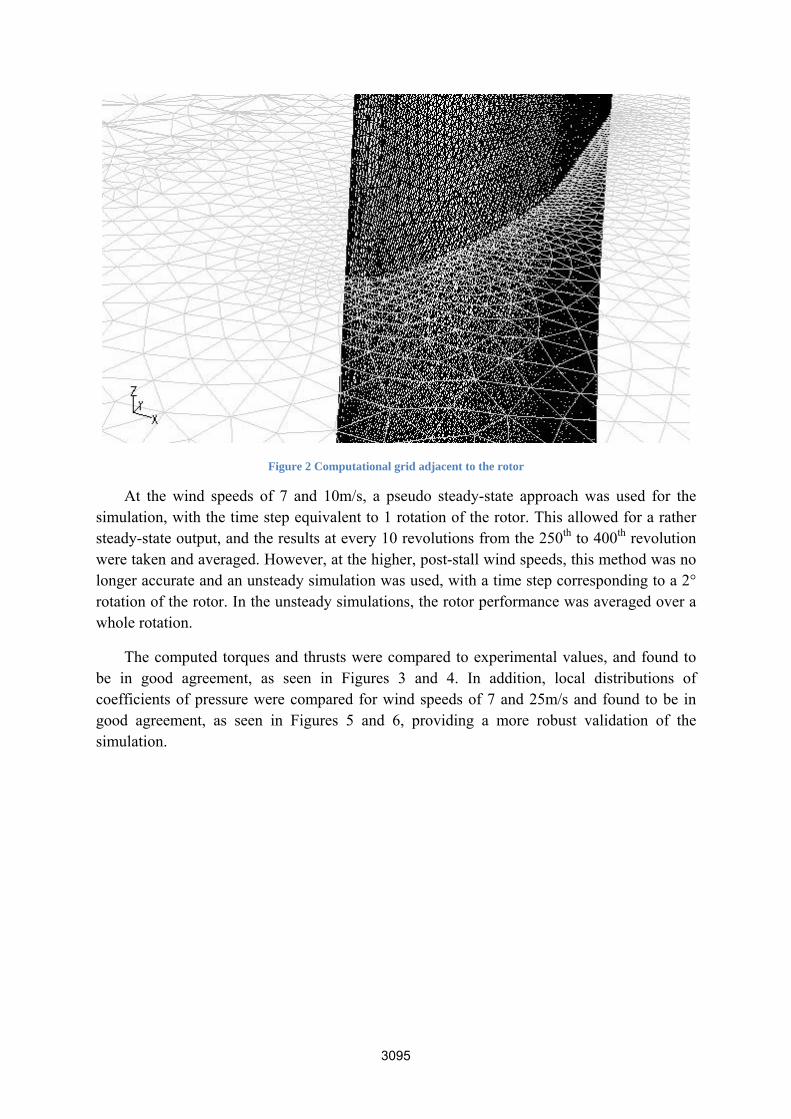
Figure 2 Computational grid adjacent to the rotor
At the wind speeds of 7 and 10m/s, a pseudo steady-state approach was used for the simulation, with the time step equivalent to 1 rotation of the rotor. This allowed for a rather steady-state output, and the results at every 10 revolutions from the 250th to 400th revolution were taken and averaged. However, at the higher, post-stall wind speeds, this method was no longer accurate and an unsteady simulation was used, with a time step corresponding to a 2° rotation of the rotor. In the unsteady simulations, the rotor performance was averaged over a whole rotation.
The computed torques and thrusts were compared to experimental values, and found to be in good agreement, as seen in Figures 3 and 4. In addition, local distributions of coefficients of pressure were compared for wind speeds of 7 and 25m/s and found to be in good agreement, as seen in Figures 5 and 6, providing a more robust validation of the simulation.

Figure 3 Comparison of computed and experimental torques
Figure 4 Comparison of computed and experimental thrusts
0
200
400
600
800
1000
1200
1400
1600
1800
5 10 15 20 25
Torque
(N.m
)
Wind Speed (m/s)
NREL UAE Phase VI
CFD Predictions
800
1300
1800
2300
2800
3300
3800
4300
5 10 15 20 25
Thrust (N
)
Wind Speed (m/s)
NREL UAE Phase VI
CFD Prediction

Figure 5 Comparison of coefficient of pressure distribution at 7m/s
Figure 6 Comparison of coefficient of pressure distribution at 25m/s
2.2 Blade Element Momentum Method
The Blade element momentum computations of the NREL Phase VI wind turbine were done using the WT_perf research code by NWTC. This is an iterative algorithm that allowed the quick computation of the turbine performance, as shown in Figure 7.

Figure 7 BEM algorithm for WT_perf design code (Maniaci, 2011)
The axial, a, and rotational, a’, induction factors are corrected using Prandtl’s tip loss factor and a Glauert correction, given by (Hibbs & Radkey, 1982):
1
10.96
18 20 3 · 50 36 12 3 436 50 0.96
( 1 )
1
1
( 2 )
Where Cnis the component of the force coefficient normal to the rotor plane, Ct is the component of the force coefficient tangential to the turbine plane, CT is the coefficient of thrust of the rotor, and F is given by:
2cos
( 3 )
Where:
2 · sin ( 4 )

B is the number of blades, R is the radius of the rotor, r is the local radius of the annular control volume, and φ is the local flow angle
The performance of the rotor was computed using 2-dimensional blade data of the S809 airfoil, but dividing the rotor into 16 equal sections, and a 0.2m radius hub. The BEM-computed torques and thrusts were compared to the CFD predictions as seen in Figures 8 and 9.
Figure 8 Comparison of computed torques for CFD and BEM theory
Figure 9 Comparison of computed thrusts for CFD and BEM theory
Large deviations from the experimental values can be seen at post-stall wind speeds, with BEM-computed thrusts especially inaccurate. This is indicative of inaccuracies of BEM-generated ADMs, which will be further quantified and qualified in this study.
0
200
400
600
800
1000
1200
1400
1600
1800
5 10 15 20 25
Torque
(N.m
)
Wind speed (m/s)
NREL UAE Phase VI
CFD Predictions
BEM
800
1300
1800
2300
2800
3300
3800
4300
5 10 15 20 25
Thrust (N
)
Wind speed (m/s)
NREL UAE Phase VI
CFD Prediction
BEM
The ADM produced using the traditional BEM algorithm was modeled using 16 concentric pressure drops, and the hub modeled as a wall. The ADM was simulated using the same domain size as the direct rotor model, using the same boundary conditions and a periodic simulation. All the actuator disc models produced in the present study consisted of tetrahedral unstructured grids, with 112000 cells.
2.3 Actuator disc-based ADM
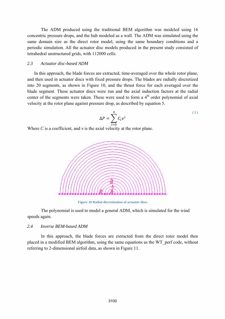
In this approach, the blade forces are extracted, time-averaged over the whole rotor plane, and then used in actuator discs with fixed pressure drops. The blades are radially discretized into 20 segments, as shown in Figure 10, and the thrust force for each averaged over the blade segment. These actuator discs were run and the axial induction factors at the radial center of the segments were taken. These were used to form a 4th order polynomial of axial velocity at the rotor plane against pressure drop, as described by equation 5.
∆ ( 5 )
Where C is a coefficient, and v is the axial velocity at the rotor plane.
Figure 10 Radial discretization of actuator discs
The polynomial is used to model a general ADM, which is simulated for the wind speeds again.
2.4 Inverse BEM-based ADM
In this approach, the blade forces are extracted from the direct rotor model then placed in a modified BEM algorithm, using the same equations as the WT_perf code, without referring to 2-dimensional airfoil data, as shown in Figure 11.

Figure 11 Inverse BEM algorithm
The resulting axial induction factors were used to create a 4th order polynomial for pressure drop against axial velocity at rotor plane (Equation 5). These were used to form an ADM, which was simulated using the same conditions as the direct rotor model.
3. RESULTS AND DISCUSSION 3.1 Axial velocity
The contours of axial velocity were plotted (Figures 12 and 13), for the direct rotor model (DRM), actuator disc-based actuator disc model (ADM-AD), inverse BEM-based actuator disc model (ADM-IB) and BEM-based actuator disc model (ADM-BEM).

actuatorproducewakes
It is clear frr disc modeed highly sifrom the d
Figure 12 C
Figure 13 C
from the conel (ADM-ADimilar resultdirect rotor
Contour plot o
Contour plot o
ntour plots tD) and invets. Furtherm
model (DR
of axial velocity
of axial velocity
that the twoerse BEM-bmore, their wRM), altho
y for wind spe
y for wind spe
o present mebased actuatwake structuough less tu
ed of 10m/s
ed of 20m/s
ethods, the tor disc modures appear urbulent. T
actuator disdel (ADM-Ito be simil
The axial v
sc-based IB) have ar to the elocities

appear accuratedisplays
ADM-Ithe flowThis malacks ofdisc mo
non-dimrotor ce8 respeFigures
to be in sime in compars lower axia
A possible IB and the Dws in the actay have conf detail in thodels compa
To ensure mensionalizenter were pectively), tos 14 and 15.
milar rangerison to theal velocities
explanatioDRM is thetuator disc mntributed tohe actuator dared to the D
a more meed axial ve
plotted at 4, o compare t
Figure 14 V
e, but the coe BEM-bases.
on for the de lack of tipmodels are
o the less nodisc modelsDRM, resul
eaningful, qelocities, loc
6 and 8 rotthe accuracy
ertical profiles
ontours coned actuator d
differences vortices prpurely axia
oisy and sms may be dulting in a mu
quantitative cal velocitietor diametery of the wa
s of axial veloc
ntain less dedisc model,
between throduced by al, and no romoother conue to the coauch poorer r
comparisoes divided brs downstreaakes and w
city for wind sp
etail. They , ADM-BEM
he both the the actuato
otational flontour lines. Larser mesh uresolution o
on, the vertiby the inletam of the ro
wake degrad
peed of 10m/s
appear to bM, which g
ADM-AD or disc modeows were simLastly, somused in the
of detail.
ical profilet velocity, fotor (x/D = dation, as sh
be more generally
and the el. Also, mulated.
me of the actuator
s of the from the 4, 6 and hown in

relativeADM-BThis macould aAnotherinto con
3.2
Figures(ADM-disc mo
The ADMely accurateBEM resultsay possibly
add additionr possibilityncentric actu
Turbule
Contour pls 16 and 17,-AD), inverodel (ADM-
Figure 15 V
M-AD and e predictions. However
y be due to nal shear foy may be thuator discs
ence intensi
ots of turbu, for the direrse BEM-ba-BEM).
ertical profiles
ADM-IB mn of the wa, slight inacthe lack of
orces in thehe need to near the hub
ity
ulence intenect rotor moased actuato
s of axial veloc
models havake velociticcuracies caf rotational e flow that w
refine the b and tip re
nsity in the odel (DRMor disc mo
city for wind sp
ve shown ies, significan be seen aflows in thwould creadiscretizati
egions.
wake are s), actuator d
odel (ADM-
peed of 20m/s
a similar cantly moreat the rotor hhe actuator date a steeperon of the a
shown for edisc-based a-IB) and B
performance accurate thub and tip disc modelsr velocity g
actuator dis
each wind sactuator disEM-based
ce, with than the regions. s, which gradient. c model
speed in sc model actuator

turbulenalmost simulat
It is apparence to replnon-existened, and tha
Figure 16 Con
Figure 17 Con
ent that bothlicate the Dnt. This canat the actuat
ntour plot of tu
ntour plot of tu
h the ADMDRM resultn possibly btor discs do
urbulence inten
urbulence inten
M-AD and At. In fact, te attributed
o not simula
nsity for wind
nsity for wind
ADM-IB methe turbulend to the fact ate tip vorti
speed of 10m/s
speed of 20m/s
ethods do nnce for the
that rotatioces, which
s
s
not producese two mo
onal flows wcan cause s
enough dels are were not shearing

effects means t
ADB-BHowevelocationthe ADM
of windpredicti= 4, 6 a
and eventuthat bounda
Indeed it isBEM modeler, this is n and intensM-AD and
To ensure ad farm wakeion), axial vand 8 respec
F
ual mixing, ary layer tur
s likely to b, which hasnot compa
sity differs. ADM-IB m
a meaningfe simulationvelocity proctively) wer
Figure 18 Verti
which resurbulence can
be the flat cis resulted in
arable with Thus, it is l
models to cr
ful, quantitan (for placemofiles at 4, 6re compared
ical profiles of
lt in turbulennot develo
ircular walln the high lthe turbule
likely that tueate a simil
ative compament optim
6 and 8 rotod, in Figures
turbulence int
ence. Also, p.
used to molevels of tuence from urbulent soularity with th
arison of axmization, peror diameterss 18 to 19.
tensity for win
the lack of
odel the huburbulence in
the DRM urce terms mhe actual flo
xial velocitirformance ps downstrea
d speed of 10m
f any physi
b of the roton those simu
simulationmust be incow.
es for the pprediction anam of the ro
m/s
ical wall
or in the ulations. , as the
cluded in
purposes nd loads
otor (x/D

accuratethe ADsame pathe threto be duto accur
turbulenhigher v
4. CON
the extrfrom a dfixed prnormal against the BEMbased oThe actactuator
F
These profiely simulate
DM-BEM mattern as th
ee actuator due to the relrately simul
It is likelynce generatvelocities, a
NCLUSION
Two methoraction of axdirect rotor ressure droto the actuavelocity prM algorithm
on which thetuator discsr disc.
Figure 19 Verti
files confirme the wind t
method, prodhe DRM simdisc modelslative coarslate the win
y that turbuted by the rand the sour
N
ods of creatxial inductimodeling op across thator disc forrofile, for a m, but withe pressure ds were mad
ical profiles of
m that the prturbine. Usiduces too m
mulations. Is are similareness of the
nd tunnel wa
ulence sourcrotor. The rorce terms ne
ting actuatoion factors fof a wind tu
he actuator dr each blademore gener
h the fixed drop againstde up of 20
turbulence int
resent mething a wall bmuch turbult is noticear and highere actuator dall boundary
ce terms arotor is seeneed to accou
or disc modfor discrete urbine. The disc for eace segment, aral actuator blade force
t velocity pr0 discrete s
tensity for win
hods do not boundary colence, and
able that abor that the D
disc meshes,y layer.
re needed n to developunt for this a
dels have bblade segmfirst metho
ch wind speand using thdisc. The s
e data, to firofile for thsegments to
d speed of 20m
produce enondition for does not geove the rotoRM simula, which are
to accuratep more turbas well.
been presentments and bd, ADM-ADeed, findinghe data to foecond meth
find the axiae actuator d
o increase th
m/s
nough turbuthe hub, as
enerally folor, turbulen
ations. This not refined
ely account bulence at th
ted, both inlade forces D, involvedg the local orm a pressuhod, ADM-Ial inductiondisc was forhe accuracy
ulence to s used in llow the
nce from is likely
d enough
for the he tip at
nvolving directly
d using a velocity ure drop IB, used n factor, rmulated. y of the

Results showed little difference between the results of the ADM-AD and ADM-IB methods. This was to be expected, since previous work by Bak et al (Bak, Fuglsang, Sorensen, Madsen, Shen, & Sorensen, 1999) showed good agreement between similar two methods for formulating airfoil lift and drag coefficients. More significant was the high accuracy of prediction of axial velocity in the wake, even at large distances downstream of the rotor, in comparison to the direct rotor model (DRM). In addition, this accuracy was significantly higher than for the actuator disc constructed using a traditional BEM method (ADM-BEM). This shows that the availability of direct rotor modeling results, or detailed experimental results both of which would likely be produced at a design stage of a commercial wind turbine, can increase the accuracy in which wind farm simulations are conducted. This can allow for far more efficient placement of wind turbines in wind farms, as well as accurate prediction of blade aeroelastic loads for a more cost-effective maintenance schedule.
However, prediction of turbulence intensity in both the ADM-AD and ADM-IB models were highly inaccurate. This is due to the fact that the actuator disc forms only a pressure discontinuity, and has no physical presence in the flow. These low turbulence intensities from the ADM-AD and ADM-IB models may have been compounded by the fact that the present study did not include rotational flows. Rotational flows may increase the shear in the wake to a level that increases the turbulence intensity. From previous literature, it can be concluded that this is unlikely to be enough, and turbulence source terms would be needed in the actuator disc to improve accuracy. However Sanderse et al noted in their review of wind turbine wake aerodynamics that in the case of an atmospheric boundary layer, the turbine-generated turbulence would be insignificant compared to atmospheric turbulence (Sanderse, van der Pijl, & Koren, Review of CFD for wind-turbine wake aerodynamics, 2011). This needs to be investigated with present models using atmospheric boundary layers.
References:
Bak, C., Fuglsang, P., Sorensen, N. N., Madsen, H. A., Shen, W., & Sorensen, J. (1999). Airfoil Characteristics for Wind Turbines. Riso National Laboratory, Technical University of Denmark. Roskilde: Riso National Laboratory.
Hand, M. M., Simms, D. A., Fingersh, L. J., Jager, D. W., Cotrell, J. R., Schreck, S., et al. (2001). Unsteady Aerodynamics Experiment Phase VI: Wind Tunnel Test Configurations and Available Data Campaigns. Golden, Colarado: National Renweable Energy Laboratory. NREL/TP-500-29955.
Hansen, M. O. (2008). Aerodynamics of Wind Turbines (2nd ed.). London, UK: Earthscan.
Hibbs, B., & Radkey, R. L. (1982). Small Wind Energy Conversion Systems (SWECS) Rotor Performance Model Comparison Study. Pasadena, California: Rockwell International Corporatio.
Maniaci, D. C. (2011). An investigation of WT_perf convergence issues. 49th AIAA Aerospace Sciences Meeting including the New Horizons Forum and Aerospace Exposition. Orlando, Florida, USA: AIAA. AIAA 2011-150.
Menter, F. R. (1994). Two-Equation Eddy Viscosity Turbulence Models for Engineering Applications. AIAA Journal, 32(8), 1598-1605.
Neustadter, H., & Spera, D. (1985). Method for evaluating wind turbine wake effects for wind farm performance. Journal of Solar Energy Engineering, 107, 240-243.
Sanderse, B. (2009). Aerodynamics of Wind Turbine Wakes. Energy Research Centre of the Netherlands.
Sanderse, B., van der Pijl, S., & Koren, B. (2011). Review of CFD for wind-turbine wake aerodynamics. Wind Energy, 14(7), 799-819.
Simms, D., Schreck, S., Hand, M., & Fingersh, L. J. (2001). NREL Unsteady Aerodynamics Experiment in the NASA-Ames Wind Tunnel: A Comparison of Predictions to Measurements. Golden, Colarado: National Renewable Energy Laboratory.