Abdomen Impact Testing of the Hybrid III - IRCOBI The Hybrid III Rail Safety (H3‐RS)...
13
Abstract The Hybrid III Rail Safety (H3‐RS) anthropometric test device was developed in the UK to evaluate abdomen and lower thorax injuries that occur when passengers impact workstation tables during train accidents. The H3‐RS is similar to the standard Hybrid III ATD, but with a more biofidelic abdomen response under table‐edge loading conditions, and with instrumentation to measure compression at multiple bilateral chest and abdomen locations. The objectives of this study are to identify a design of abdomen that is biofidelic and that produces consistent results under a range of impact conditions. Candidate H3‐RS abdomen designs were tested according to the NHTSA targets for frontal impact dummies. Additional bar impactors with different mass, bar diameter and impact velocity were also used to evaluate the measurement sensitivity of the ATD. All three abdomen designs met the certification and biofidelity requirements for frontal impact dummies. The chosen design gave some coupling between the abdomen and the thorax, which would be more humanlike than having entirely separate abdomen and rib structures. It also prevents workstation tables from penetrating between the abdomen and the rib structures, therefore (partially) bypassing chest and abdomen deflection instrumentation. The abdomen showed good repeatability and was appropriately sensitive to impact location and velocity. Keywords Hybrid III Rail Safety dummy (H3‐RS), anthropometric test device (ATD), abdomen biofidelity, workstation table safety, rail safety. I. INTRODUCTION The Hybrid III Rail Safety dummy (H3‐RS) anthropometric test device (ATD) is a crash test dummy developed in the UK to evaluate abdomen and lower thorax injuries that occur when passengers impact workstation tables during train accidents. The H3‐RS is similar to the standard Hybrid III 50th percentile male ATD – which is used in car crash test regulations [1,2] and consumer information programmes [3‐5] worldwide – but with a more humanlike abdomen response under table‐edge loading conditions and with additional instrumentation to measure compression and rate of compression at multiple bilateral locations in the chest and abdomen. The H3‐RS has been designed to meet the biofidelity targets specified by NHTSA for the next‐generation frontal impact car crash test ATD, called THOR (Test device for Human Occupant Restraint) [6]. The biofidelity targets define the response of a human to various loading conditions and help to ensure that the response of an ATD design in crash tests is human‐like [7]. The H3‐RS has also been designed to meet the certification requirements for the THOR ATD [8]. A goal of the testing described in this paper was to identify a design of abdomen that is biofidelic and that produces consistent results under a range of impact conditions. If these tests are successful, the ATD abdomen design can be finalised. The Federal Railroad Administration (FRA) and the Volpe National Transportation Systems Center (Volpe Center) have an interest in seeing the H3‐RS design finalised, because use of such an ATD is specified for dynamic testing in APTA PR‐CS‐S‐018‐13 – Fixed Workstation Tables in Passenger Rail Cars [9]. D. Hynd (e‐mail: [email protected]; tel: +44 1344 770 310) is Head of Biomechanics at the Transport Research Laboratory, UK. J. A. Carroll was a Principal Researcher in the Safety and Technology Group at the Transport Research Laboratory and is now at Bristol Cars Ltd. K. Severson is a Senior Mechanical Engineer at the Volpe National Transportation Systems Center, US Department of Transportation, USA. Abdomen Impact Testing of the Hybrid III Rail Safety (H3‐RS) Anthropometric Test Device David Hynd, Jolyon A. Carroll and Kristine Severson IRC-17-40 IRCOBI Conference 2017 -244-
Transcript of Abdomen Impact Testing of the Hybrid III - IRCOBI The Hybrid III Rail Safety (H3‐RS)...
Abstract The Hybrid III Rail Safety (H3‐RS) anthropometric test device was developed in the UK to
evaluate abdomen and lower thorax injuries that occur when passengers impact workstation tables during train
accidents. The H3‐RS is similar to the standard Hybrid III ATD, but with a more biofidelic abdomen response
under table‐edge loading conditions, and with instrumentation to measure compression at multiple bilateral
chest and abdomen locations. The objectives of this study are to identify a design of abdomen that is biofidelic
and that produces consistent results under a range of impact conditions.
Candidate H3‐RS abdomen designs were tested according to the NHTSA targets for frontal impact dummies.
Additional bar impactors with different mass, bar diameter and impact velocity were also used to evaluate the
measurement sensitivity of the ATD. All three abdomen designs met the certification and biofidelity
requirements for frontal impact dummies. The chosen design gave some coupling between the abdomen and
the thorax, which would be more humanlike than having entirely separate abdomen and rib structures. It also
prevents workstation tables from penetrating between the abdomen and the rib structures, therefore (partially)
bypassing chest and abdomen deflection instrumentation. The abdomen showed good repeatability and was
appropriately sensitive to impact location and velocity.
Keywords Hybrid III Rail Safety dummy (H3‐RS), anthropometric test device (ATD), abdomen biofidelity, workstation table safety, rail safety.
I. INTRODUCTION
The Hybrid III Rail Safety dummy (H3‐RS) anthropometric test device (ATD) is a crash test dummy developed
in the UK to evaluate abdomen and lower thorax injuries that occur when passengers impact workstation tables
during train accidents. The H3‐RS is similar to the standard Hybrid III 50th percentile male ATD – which is used in
car crash test regulations [1,2] and consumer information programmes [3‐5] worldwide – but with a more
humanlike abdomen response under table‐edge loading conditions and with additional instrumentation to
measure compression and rate of compression at multiple bilateral locations in the chest and abdomen.
The H3‐RS has been designed to meet the biofidelity targets specified by NHTSA for the next‐generation
frontal impact car crash test ATD, called THOR (Test device for Human Occupant Restraint) [6]. The biofidelity
targets define the response of a human to various loading conditions and help to ensure that the response of an
ATD design in crash tests is human‐like [7]. The H3‐RS has also been designed to meet the certification
requirements for the THOR ATD [8].
A goal of the testing described in this paper was to identify a design of abdomen that is biofidelic and that
produces consistent results under a range of impact conditions. If these tests are successful, the ATD abdomen
design can be finalised. The Federal Railroad Administration (FRA) and the Volpe National Transportation
Systems Center (Volpe Center) have an interest in seeing the H3‐RS design finalised, because use of such an ATD
is specified for dynamic testing in APTA PR‐CS‐S‐018‐13 – Fixed Workstation Tables in Passenger Rail Cars [9].
D. Hynd (e‐mail: [email protected]; tel: +44 1344 770 310) is Head of Biomechanics at the Transport Research Laboratory, UK. J. A. Carroll was a Principal Researcher in the Safety and Technology Group at the Transport Research Laboratory and is now at Bristol Cars Ltd. K. Severson is a Senior Mechanical Engineer at the Volpe National Transportation Systems Center, US Department of Transportation, USA.
Abdomen Impact Testing of the Hybrid III Rail Safety (H3‐RS) Anthropometric Test Device
David Hynd, Jolyon A. Carroll and Kristine Severson
IRC-17-40 IRCOBI Conference 2017
-244-
II. METHODS
The first part of this study evaluated the biofidelity and certification response of three prototype abdomen
designs:
A) A design that filled the void between the pelvis, lumbar spine and rib cage;
B) A design identical to A, but coupled to front of the rib cage with hook‐and‐loop fabric, in a similar
manner to the THOR dummy;
C) A design identical to A, but extended 20 mm up inside the rib cage to help prevent penetration of
narrow table edges between the top of the abdomen bag and the rib cage.
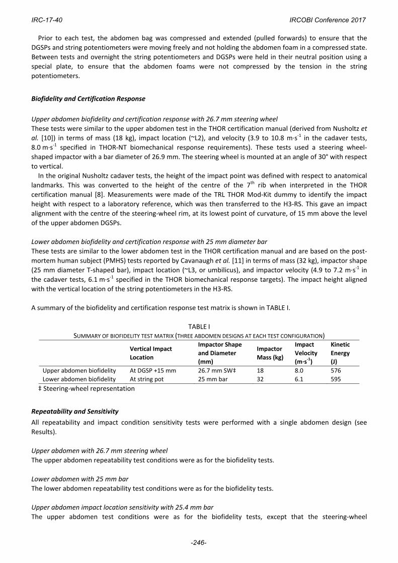
A single abdomen design was then tested to determine repeatability and also the sensitivity of the design to
impact location, impact velocity, and impactor geometry. The photograph in Fig. 1 illustrates the vertical impact
location identifications (either aligned with the upper abdominal Double Gimballed String Potentiometers
(DGSPs) or with the lower abdominal string potentiometers). The ATD also has bilateral tri‐axial deflection
transducers located in the upper and lower thorax regions shown in Fig. 1.
Fig. 1. Approximate positions of H3‐RS thorax and abdomen body regions.
Test Procedure
The test procedure was based on the THOR‐NT certification manual [8]. The dummy was seated on a scissor‐lift
table to facilitate adjustment of the impact height of the pendulum relative to the dummy. For simplicity and
to align with anticipated changes in the THOR certification requirements, the ATD was seated on the painted
metal surface of the supporting scissor‐lift table. This deviates from the original Nusholtz and Kaiker [10] upper
abdomen cadaver test conditions, which had a plastic sheet (‘Visqueen’ low density polyethylene sheet)
covering the table, with a sheet of Styrofoam between the plastic sheet and the cadaver. Similarly, the original
Cavanaugh et al. [11] cadaver tests had a thin plastic sheet covering the table.
Impact force was measured using a uniaxial accelerometer. The lateral and vertical velocity components of
the impactor prior to contact with the ATD were monitored using additional uniaxial accelerometers close to
the centre of mass of the pendulum and were less than 0.1 m∙s‐1. Each test was captured using high‐speed
(1,000 frames per second) digital cameras providing a frontal view and a side view, and the thorax and
abdomen (including instrumentation) were visually inspected after each test to check for damage.
IRC-17-40 IRCOBI Conference 2017
-245-
Prior to each test, the abdomen bag was compressed and extended (pulled forwards) to ensure that the
DGSPs and string potentiometers were moving freely and not holding the abdomen foam in a compressed state.
Between tests and overnight the string potentiometers and DGSPs were held in their neutral position using a
special plate, to ensure that the abdomen foams were not compressed by the tension in the string
potentiometers.
Biofidelity and Certification Response
Upper abdomen biofidelity and certification response with 26.7 mm steering wheel
These tests were similar to the upper abdomen test in the THOR certification manual (derived from Nusholtz et
al. [10]) in terms of mass (18 kg), impact location (~L2), and velocity (3.9 to 10.8 m∙s‐1 in the cadaver tests,
8.0 m∙s‐1 specified in THOR‐NT biomechanical response requirements). These tests used a steering wheel‐
shaped impactor with a bar diameter of 26.9 mm. The steering wheel is mounted at an angle of 30° with respect
to vertical.
In the original Nusholtz cadaver tests, the height of the impact point was defined with respect to anatomical
landmarks. This was converted to the height of the centre of the 7th rib when interpreted in the THOR
certification manual [8]. Measurements were made of the TRL THOR Mod‐Kit dummy to identify the impact
height with respect to a laboratory reference, which was then transferred to the H3‐RS. This gave an impact
alignment with the centre of the steering‐wheel rim, at its lowest point of curvature, of 15 mm above the level
of the upper abdomen DGSPs.
Lower abdomen biofidelity and certification response with 25 mm diameter bar
These tests are similar to the lower abdomen test in the THOR certification manual and are based on the post‐
mortem human subject (PMHS) tests reported by Cavanaugh et al. [11] in terms of mass (32 kg), impactor shape
(25 mm diameter T‐shaped bar), impact location (~L3, or umbilicus), and impactor velocity (4.9 to 7.2 m∙s‐1 in
the cadaver tests, 6.1 m∙s‐1 specified in the THOR biomechanical response targets). The impact height aligned
with the vertical location of the string potentiometers in the H3‐RS.
A summary of the biofidelity and certification response test matrix is shown in TABLE I.
TABLE I SUMMARY OF BIOFIDELITY TEST MATRIX (THREE ABDOMEN DESIGNS AT EACH TEST CONFIGURATION)
Vertical Impact
Location
Impactor Shape
and Diameter
(mm)
Impactor
Mass (kg)
Impact
Velocity
(m∙s‐1)
Kinetic
Energy
(J)
Upper abdomen biofidelity At DGSP +15 mm 26.7 mm SW‡ 18 8.0 576
Lower abdomen biofidelity At string pot 25 mm bar 32 6.1 595
‡ Steering‐wheel representation
Repeatability and Sensitivity
All repeatability and impact condition sensitivity tests were performed with a single abdomen design (see
Results).
Upper abdomen with 26.7 mm steering wheel
The upper abdomen repeatability test conditions were as for the biofidelity tests.
Lower abdomen with 25 mm bar
The lower abdomen repeatability test conditions were as for the biofidelity tests.
Upper abdomen impact location sensitivity with 25.4 mm bar
The upper abdomen test conditions were as for the biofidelity tests, except that the steering‐wheel
IRC-17-40 IRCOBI Conference 2017
-246-
representation was replaced with a 25.4 mm‐diameter cylindrical bar, as this geometry is more representative
of a workstation table, and the mass of the bar impactor was reduced to 18 kg. The baseline alignment was as
for the biofidelity tests (DGSP +15 mm), with tests at +25 mm, ‐25 mm and ‐50 mm intervals above and below
this level. An additional test was also performed with the impactor aligned with the DGSP.
Lower abdomen impact location sensitivity with 25 mm diameter bar
The lower abdomen repeatability test conditions were as for the biofidelity tests, with baseline impact
alignment with the string pot and also at +25 mm above this level.
Upper abdomen impactor thickness sensitivity with 50 mm bar
These tests repeated the upper abdomen impact location sensitivity tests with a 50 mm bar impactor.
Lower abdomen impactor thickness sensitivity with 50.8 mm bar
These tests repeated the lower abdomen impact location sensitivity tests with a 50.8 mm bar impactor.
Upper abdomen impactor velocity sensitivity with 50 mm bar
These tests were as for the biofidelity tests, but with a 50 mm bar impactor and an impact velocity of 6.0 and
7.0 m∙s‐1 (biofidelity severity ‐1 and ‐2 m∙s‐1).
Lower abdomen impactor velocity sensitivity with 50.8 mm bar
These tests were as for the biofidelity tests, but with a 50.8 mm bar impactor and an impact velocity of 5.1 and
7.1 m∙s‐1 (biofidelity severity ±1 m∙s‐1).
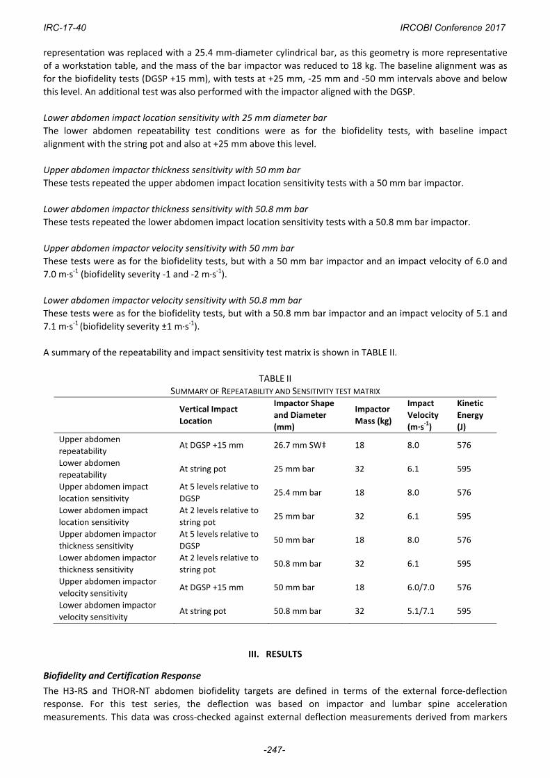
A summary of the repeatability and impact sensitivity test matrix is shown in TABLE II.
TABLE II SUMMARY OF REPEATABILITY AND SENSITIVITY TEST MATRIX
Vertical Impact
Location
Impactor Shape
and Diameter
(mm)
Impactor
Mass (kg)
Impact
Velocity
(m∙s‐1)
Kinetic
Energy
(J)
Upper abdomen
repeatability At DGSP +15 mm 26.7 mm SW‡ 18 8.0 576
Lower abdomen
repeatability At string pot 25 mm bar 32 6.1 595
Upper abdomen impact
location sensitivity
At 5 levels relative to
DGSP 25.4 mm bar 18 8.0 576
Lower abdomen impact
location sensitivity
At 2 levels relative to
string pot 25 mm bar 32 6.1 595
Upper abdomen impactor
thickness sensitivity
At 5 levels relative to
DGSP 50 mm bar 18 8.0 576
Lower abdomen impactor
thickness sensitivity
At 2 levels relative to
string pot 50.8 mm bar 32 6.1 595
Upper abdomen impactor
velocity sensitivity At DGSP +15 mm 50 mm bar 18 6.0/7.0 576
Lower abdomen impactor
velocity sensitivity At string pot 50.8 mm bar 32 5.1/7.1 595
III. RESULTS
Biofidelity and Certification Response
The H3‐RS and THOR‐NT abdomen biofidelity targets are defined in terms of the external force‐deflection
response. For this test series, the deflection was based on impactor and lumbar spine acceleration
measurements. This data was cross‐checked against external deflection measurements derived from markers
IRC-17-40 IRCOBI Conference 2017
-247-
placed on the impactor and on the lumbar spine of the dummy (which replicated the method used in the
original PMHS tests), and the two approaches were found to be comparable. The graphs in this section also
show the force‐deflection response in terms of the internally measured deflection (DGSP X‐axis deflection or
string potentiometer change of length), compared with the certification requirements for the H3‐RS and THOR
abdomen.
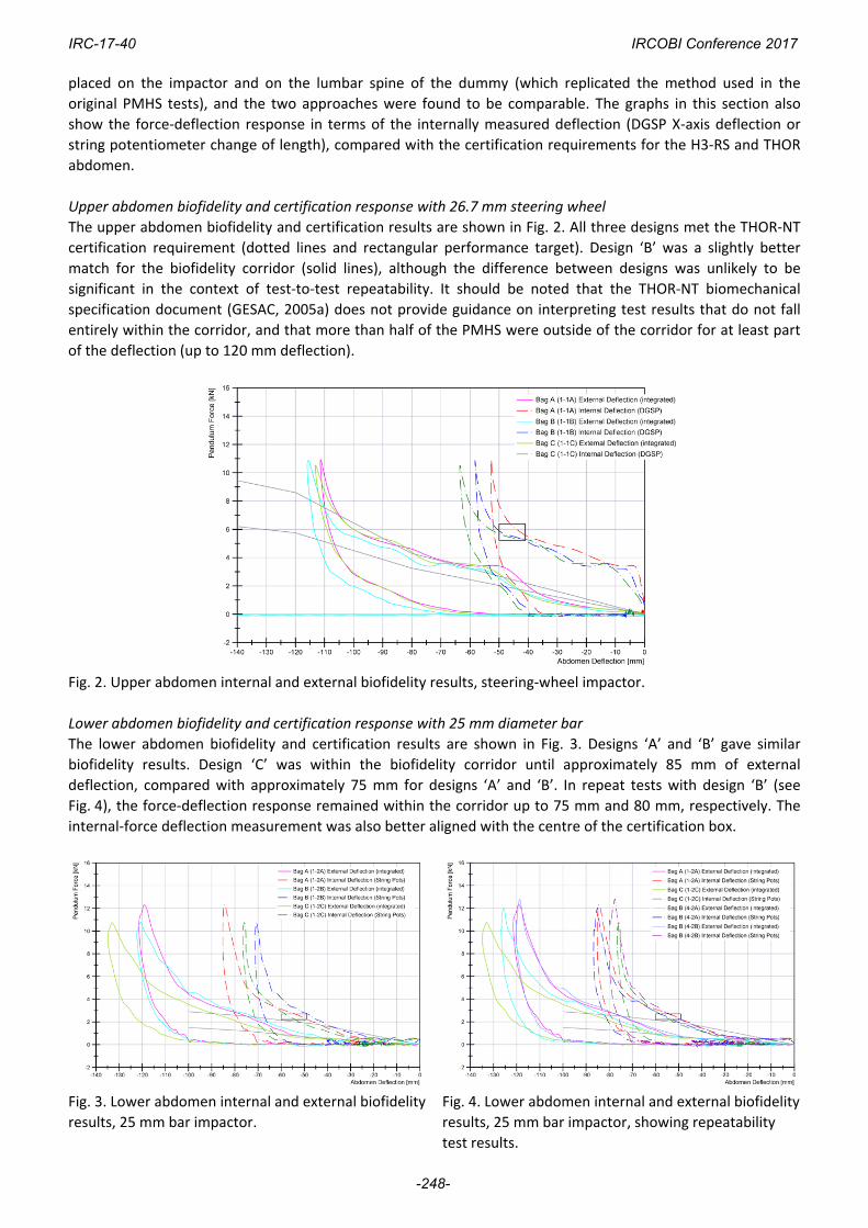
Upper abdomen biofidelity and certification response with 26.7 mm steering wheel
The upper abdomen biofidelity and certification results are shown in Fig. 2. All three designs met the THOR‐NT
certification requirement (dotted lines and rectangular performance target). Design ‘B’ was a slightly better
match for the biofidelity corridor (solid lines), although the difference between designs was unlikely to be
significant in the context of test‐to‐test repeatability. It should be noted that the THOR‐NT biomechanical
specification document (GESAC, 2005a) does not provide guidance on interpreting test results that do not fall
entirely within the corridor, and that more than half of the PMHS were outside of the corridor for at least part
of the deflection (up to 120 mm deflection).
Fig. 2. Upper abdomen internal and external biofidelity results, steering‐wheel impactor.
Lower abdomen biofidelity and certification response with 25 mm diameter bar
The lower abdomen biofidelity and certification results are shown in Fig. 3. Designs ‘A’ and ‘B’ gave similar
biofidelity results. Design ‘C’ was within the biofidelity corridor until approximately 85 mm of external
deflection, compared with approximately 75 mm for designs ‘A’ and ‘B’. In repeat tests with design ‘B’ (see
Fig. 4), the force‐deflection response remained within the corridor up to 75 mm and 80 mm, respectively. The
internal‐force deflection measurement was also better aligned with the centre of the certification box.
Fig. 3. Lower abdomen internal and external biofidelity
results, 25 mm bar impactor.
Fig. 4. Lower abdomen internal and external biofidelity
results, 25 mm bar impactor, showing repeatability
test results.
IRC-17-40 IRCOBI Conference 2017
-248-
Given that the performance of all three abdomen bag designs was comparable in meeting the biofidelity
(and certification) targets, additional attributes were considered in selecting a design for evaluation in the
remaining tests. Design ‘B’ was selected for the remainder of the test programme because it was considered to
have the most appropriate coupling between the abdomen to the ribs; this would be more human‐like than
having entirely separate abdomen and rib structures, and it would make it extremely unlikely that a table could
bypass the abdomen transducers by penetrating between the abdomen bag and the ribs, which would be a
non‐human‐like behaviour. A similar approach is used in the THOR‐NT design, where the upper abdomen bag is
attached directly to the lower three ribs, and the lower abdomen bag is coupled to the upper abdomen bag
using a hook‐and‐eye system. Furthermore, the jacket of the THOR NT dummy features a crotch strap that
prevents the jacket from riding up, which will help prevent penetration between the rib cage and the abdomen.
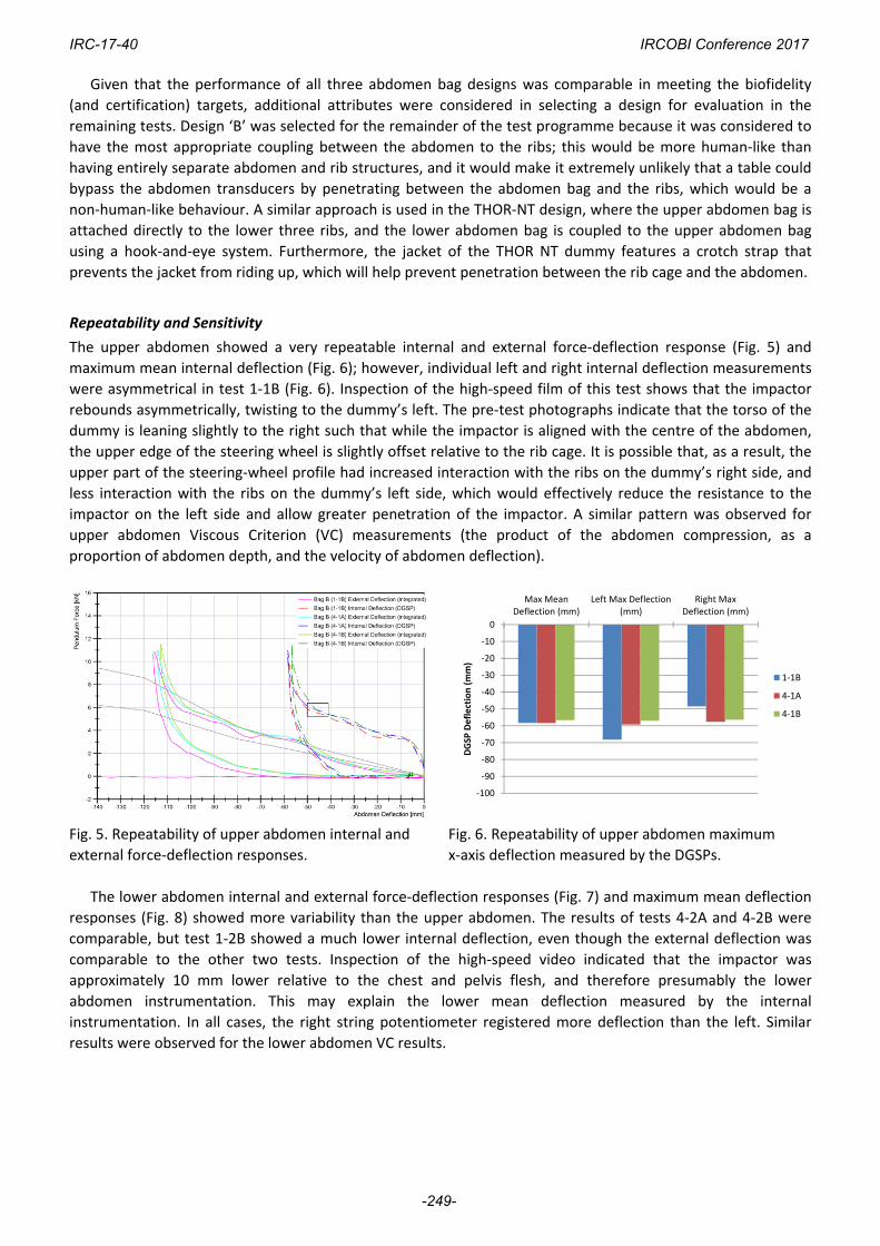
Repeatability and Sensitivity
The upper abdomen showed a very repeatable internal and external force‐deflection response (Fig. 5) and
maximum mean internal deflection (Fig. 6); however, individual left and right internal deflection measurements
were asymmetrical in test 1‐1B (Fig. 6). Inspection of the high‐speed film of this test shows that the impactor
rebounds asymmetrically, twisting to the dummy’s left. The pre‐test photographs indicate that the torso of the
dummy is leaning slightly to the right such that while the impactor is aligned with the centre of the abdomen,
the upper edge of the steering wheel is slightly offset relative to the rib cage. It is possible that, as a result, the
upper part of the steering‐wheel profile had increased interaction with the ribs on the dummy’s right side, and
less interaction with the ribs on the dummy’s left side, which would effectively reduce the resistance to the
impactor on the left side and allow greater penetration of the impactor. A similar pattern was observed for
upper abdomen Viscous Criterion (VC) measurements (the product of the abdomen compression, as a
proportion of abdomen depth, and the velocity of abdomen deflection).
Fig. 5. Repeatability of upper abdomen internal and
external force‐deflection responses.
Fig. 6. Repeatability of upper abdomen maximum
x‐axis deflection measured by the DGSPs.
The lower abdomen internal and external force‐deflection responses (Fig. 7) and maximum mean deflection
responses (Fig. 8) showed more variability than the upper abdomen. The results of tests 4‐2A and 4‐2B were
comparable, but test 1‐2B showed a much lower internal deflection, even though the external deflection was
comparable to the other two tests. Inspection of the high‐speed video indicated that the impactor was
approximately 10 mm lower relative to the chest and pelvis flesh, and therefore presumably the lower
abdomen instrumentation. This may explain the lower mean deflection measured by the internal
instrumentation. In all cases, the right string potentiometer registered more deflection than the left. Similar
results were observed for the lower abdomen VC results.
‐100
‐90
‐80
‐70
‐60
‐50
‐40
‐30
‐20
‐10
0
Max MeanDeflection (mm)
Left Max Deflection(mm)
Right MaxDeflection (mm)
DGSP
Deflection (mm)
1‐1B
4‐1A
4‐1B
IRC-17-40 IRCOBI Conference 2017
-249-
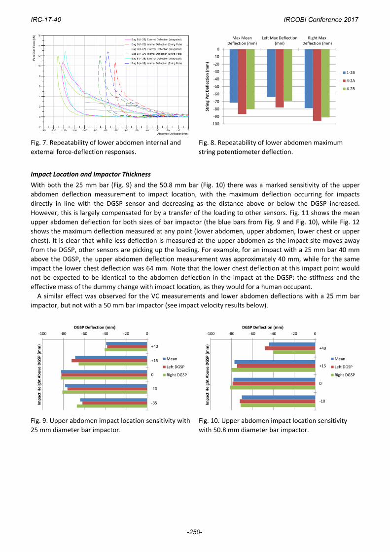
Fig. 7. Repeatability of lower abdomen internal and
external force‐deflection responses.
Fig. 8. Repeatability of lower abdomen maximum
string potentiometer deflection.
Impact Location and Impactor Thickness
With both the 25 mm bar (Fig. 9) and the 50.8 mm bar (Fig. 10) there was a marked sensitivity of the upper
abdomen deflection measurement to impact location, with the maximum deflection occurring for impacts
directly in line with the DGSP sensor and decreasing as the distance above or below the DGSP increased.
However, this is largely compensated for by a transfer of the loading to other sensors. Fig. 11 shows the mean
upper abdomen deflection for both sizes of bar impactor (the blue bars from Fig. 9 and Fig. 10), while Fig. 12
shows the maximum deflection measured at any point (lower abdomen, upper abdomen, lower chest or upper
chest). It is clear that while less deflection is measured at the upper abdomen as the impact site moves away
from the DGSP, other sensors are picking up the loading. For example, for an impact with a 25 mm bar 40 mm
above the DGSP, the upper abdomen deflection measurement was approximately 40 mm, while for the same
impact the lower chest deflection was 64 mm. Note that the lower chest deflection at this impact point would
not be expected to be identical to the abdomen deflection in the impact at the DGSP: the stiffness and the
effective mass of the dummy change with impact location, as they would for a human occupant.
A similar effect was observed for the VC measurements and lower abdomen deflections with a 25 mm bar
impactor, but not with a 50 mm bar impactor (see impact velocity results below).
Fig. 9. Upper abdomen impact location sensitivity with
25 mm diameter bar impactor.
Fig. 10. Upper abdomen impact location sensitivity
with 50.8 mm diameter bar impactor.
‐100
‐90
‐80
‐70
‐60
‐50
‐40
‐30
‐20
‐10
0
Max MeanDeflection (mm)
Left Max Deflection(mm)
Right MaxDeflection (mm)
String Pot Deflection (mm)
1‐2B
4‐2A
4‐2B
‐100 ‐80 ‐60 ‐40 ‐20 0
+40
+15
0
‐10
‐35
DGSP Deflection (mm)
Impact Height Above
DGSP
(mm)
Mean
Left DGSP
Right DGSP
‐100 ‐80 ‐60 ‐40 ‐20 0
+40
+15
0
‐10
DGSP Deflection (mm)
Impact Height Above
DGSP
(mm)
Mean
Left DGSP
Right DGSP
IRC-17-40 IRCOBI Conference 2017
-250-
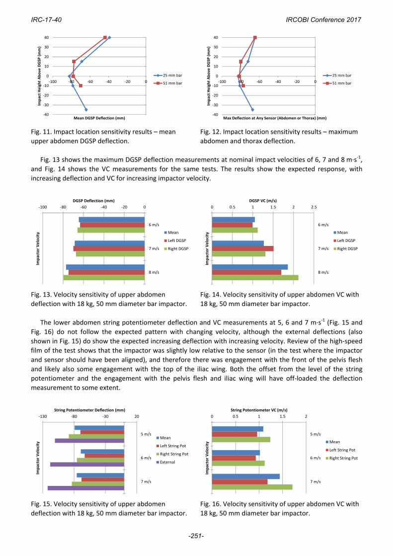
Fig. 11. Impact location sensitivity results – mean
upper abdomen DGSP deflection.
Fig. 12. Impact location sensitivity results – maximum
abdomen and thorax deflection.
Fig. 13 shows the maximum DGSP deflection measurements at nominal impact velocities of 6, 7 and 8 m∙s‐1,
and Fig. 14 shows the VC measurements for the same tests. The results show the expected response, with
increasing deflection and VC for increasing impactor velocity.
Fig. 13. Velocity sensitivity of upper abdomen
deflection with 18 kg, 50 mm diameter bar impactor.
Fig. 14. Velocity sensitivity of upper abdomen VC with
18 kg, 50 mm diameter bar impactor.
The lower abdomen string potentiometer deflection and VC measurements at 5, 6 and 7 m∙s‐1 (Fig. 15 and
Fig. 16) do not follow the expected pattern with changing velocity, although the external deflections (also
shown in Fig. 15) do show the expected increasing deflection with increasing velocity. Review of the high‐speed
film of the test shows that the impactor was slightly low relative to the sensor (in the test where the impactor
and sensor should have been aligned), and therefore there was engagement with the front of the pelvis flesh
and likely also some engagement with the top of the iliac wing. Both the offset from the level of the string
potentiometer and the engagement with the pelvis flesh and iliac wing will have off‐loaded the deflection
measurement to some extent.
Fig. 15. Velocity sensitivity of upper abdomen
deflection with 18 kg, 50 mm diameter bar impactor.
Fig. 16. Velocity sensitivity of upper abdomen VC with
18 kg, 50 mm diameter bar impactor.
‐40
‐30
‐20
‐10
0
10
20
30
40
‐100 ‐80 ‐60 ‐40 ‐20 0
Impact Height Above
DGSP
(mm)
Mean DGSP Deflection (mm)
25 mm bar
51 mm bar
‐40
‐30
‐20
‐10
0
10
20
30
40
‐100 ‐80 ‐60 ‐40 ‐20 0
Impact Height Above DGSP
(mm)
Max Deflection at Any Sensor (Abdomen or Thorax) (mm)
25 mm bar
51 mm bar
‐100 ‐80 ‐60 ‐40 ‐20 0
6 m/s
7 m/s
8 m/s
DGSP Deflection (mm)
Impactor Velocity Mean
Left DGSP
Right DGSP
0 0.5 1 1.5 2 2.5
6 m/s
7 m/s
8 m/s
DGSP VC (m/s)
Impactor Velocity Mean
Left DGSP
Right DGSP
‐130 ‐80 ‐30 20
5 m/s
6 m/s
7 m/s
String Potentiometer Deflection (mm)
Impactor Velocity
Mean
Left String Pot
Right String Pot
External
0 0.5 1 1.5 2
5 m/s
6 m/s
7 m/s
String Potentiometer VC (m/s)
Impactor Velocity Mean
Left String Pot
Right String Pot
IRC-17-40 IRCOBI Conference 2017
-251-
IV. DISCUSSION
Biofidelity Test Conditions
The 8 g crash pulse used in the APTA standard is intended to represent an accident in which the structure
protecting the occupied volume has crumpled, or begun to crush, thus generating the largest possible force and
the largest possible acceleration. The closing speed of an inline train‐to‐train accident required to initiate crush
of the occupied volume varies between ~24 and 48 km/h [12].The relative velocity of an occupant with a table
edge is known as the secondary impact velocity (SIV), and it is dependent on the collision pulse and the initial
displacement between the occupant and the table edge. The abdomen biofidelity test conditions are at the
upper end of the SIV for likely abdomen‐to‐table‐edge initial displacements.
While some new abdomen biofidelity data is available (e.g. [13]), these relate primarily to seat‐belt loading
to the abdomen and the THOR biofidelity requirements remain based on the Cavanaugh and Nusholtz data.
Upper Abdomen Biofidelity
The upper abdomen biofidelity target for the H3‐RS is identical to that for the THOR‐NT dummy, which is based
on six PMHS tests undertaken by Nusholtz and Kaiker [10]. There is no information in the original reference
regarding the injuries sustained by the six PMHS in the test series on which the biofidelity target is based. The
biofidelity test involves impacting the upper abdomen with a rigid steel representation of the lower edge of a
steering wheel. It should be noted that the lateral aspects of the steering wheel also interact with the lower
ribs, both in the original PMHS tests and with the THOR‐NT and the H3‐RS.
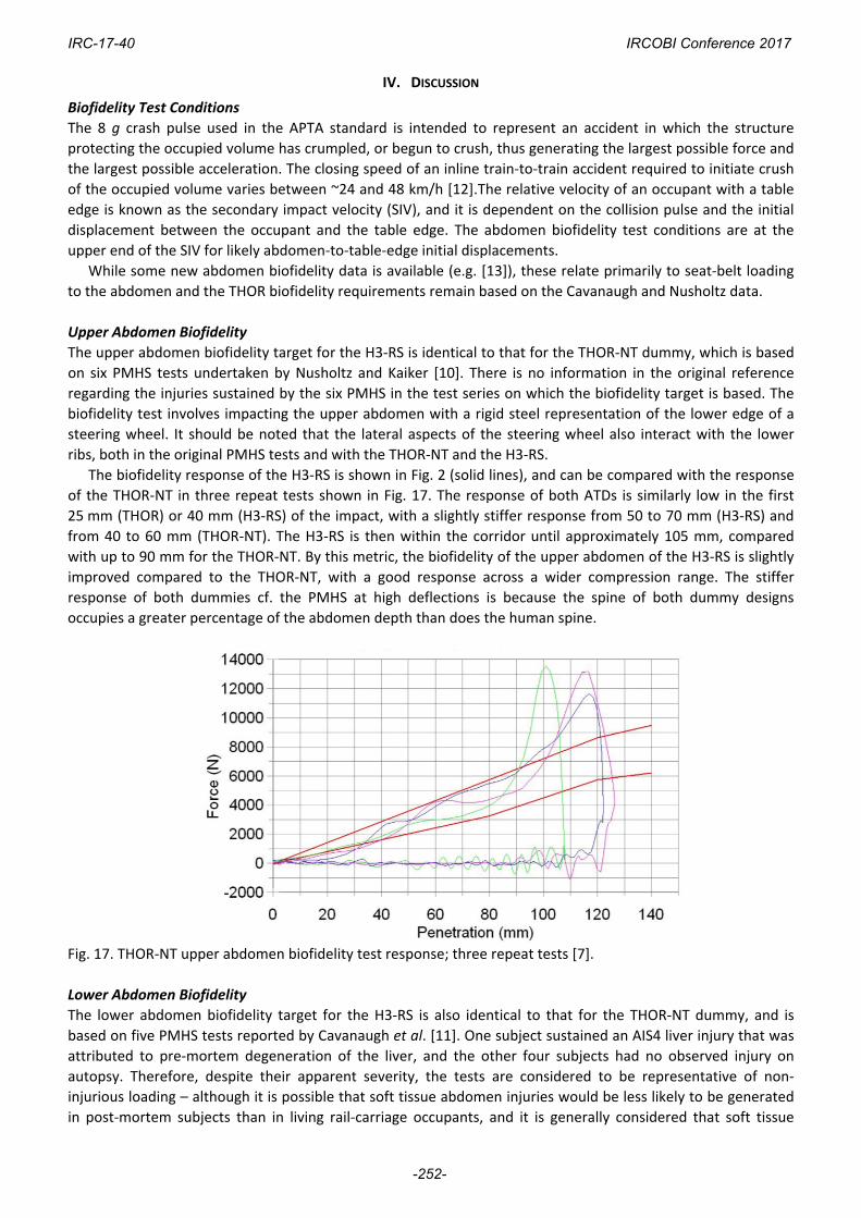
The biofidelity response of the H3‐RS is shown in Fig. 2 (solid lines), and can be compared with the response
of the THOR‐NT in three repeat tests shown in Fig. 17. The response of both ATDs is similarly low in the first
25 mm (THOR) or 40 mm (H3‐RS) of the impact, with a slightly stiffer response from 50 to 70 mm (H3‐RS) and
from 40 to 60 mm (THOR‐NT). The H3‐RS is then within the corridor until approximately 105 mm, compared
with up to 90 mm for the THOR‐NT. By this metric, the biofidelity of the upper abdomen of the H3‐RS is slightly
improved compared to the THOR‐NT, with a good response across a wider compression range. The stiffer
response of both dummies cf. the PMHS at high deflections is because the spine of both dummy designs
occupies a greater percentage of the abdomen depth than does the human spine.
Fig. 17. THOR‐NT upper abdomen biofidelity test response; three repeat tests [7].
Lower Abdomen Biofidelity
The lower abdomen biofidelity target for the H3‐RS is also identical to that for the THOR‐NT dummy, and is
based on five PMHS tests reported by Cavanaugh et al. [11]. One subject sustained an AIS4 liver injury that was
attributed to pre‐mortem degeneration of the liver, and the other four subjects had no observed injury on
autopsy. Therefore, despite their apparent severity, the tests are considered to be representative of non‐
injurious loading – although it is possible that soft tissue abdomen injuries would be less likely to be generated
in post‐mortem subjects than in living rail‐carriage occupants, and it is generally considered that soft tissue
IRC-17-40 IRCOBI Conference 2017
-252-
injuries are more difficult to detect from PMHS tests than bone fractures.
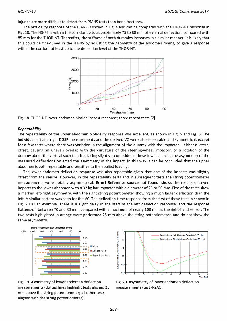
The biofidelity response of the H3‐RS is shown in Fig. 4 and can be compared with the THOR‐NT response in
Fig. 18. The H3‐RS is within the corridor up to approximately 75 to 80 mm of external deflection, compared with
85 mm for the THOR‐NT. Thereafter, the stiffness of both dummies increases in a similar manner. It is likely that
this could be fine‐tuned in the H3‐RS by adjusting the geometry of the abdomen foams, to give a response
within the corridor at least up to the deflection level of the THOR‐NT.
Fig. 18. THOR‐NT lower abdomen biofidelity test response; three repeat tests [7].
Repeatability
The repeatability of the upper abdomen biofidelity response was excellent, as shown in Fig. 5 and Fig. 6. The
individual left and right DGSP measurements and the derived VC were also repeatable and symmetrical, except
for a few tests where there was variation in the alignment of the dummy with the impactor – either a lateral
offset, causing an uneven overlap with the curvature of the steering‐wheel impactor, or a rotation of the
dummy about the vertical such that it is facing slightly to one side. In these few instances, the asymmetry of the
measured deflections reflected the asymmetry of the impact. In this way it can be concluded that the upper
abdomen is both repeatable and sensitive to the applied loading.
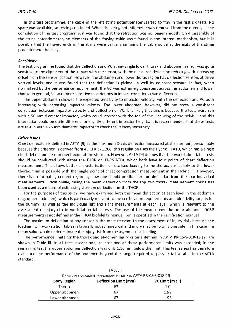
The lower abdomen deflection response was also repeatable given that one of the impacts was slightly
offset from the sensor. However, in the repeatability tests and in subsequent tests the string potentiometer
measurements were notably asymmetrical. Error! Reference source not found. shows the results of seven
impacts to the lower abdomen with a 32 kg bar impactor with a diameter of 25 or 50 mm. Five of the tests show
a marked left‐right asymmetry, with the right string potentiometer showing a much larger deflection than the
left. A similar pattern was seen for the VC. The deflection‐time response from the first of these tests is shown in
Fig. 20 as an example. There is a slight delay in the start of the left deflection response, and the response
flattens‐off between 70 and 80 mm, compared with a maximum of nearly 100 mm at the right‐hand sensor. The
two tests highlighted in orange were performed 25 mm above the string potentiometer, and do not show the
same asymmetry.
Fig. 19. Asymmetry of lower abdomen deflection
measurements (dotted lines highlight tests aligned 25
mm above the string potentiometer; all other tests
aligned with the string potentiometer).
Fig. 20. Asymmetry of lower abdomen deflection
measurements (test 4‐2A).
‐120 ‐100 ‐80 ‐60 ‐40 ‐20 0
4‐2A
4‐2B
2‐2B
3‐2A
3‐2B
5‐2A
5‐2B
String Potentiometer Deflection (mm)
Mean
Left String Pot
Right String Pot
IRC-17-40 IRCOBI Conference 2017
-253-
In this test programme, the cable of the left string potentiometer started to fray in the first six tests. No
spare was available, so testing continued. When the string potentiometer was removed from the dummy at the
completion of the test programme, it was found that the retraction was no longer smooth. On disassembly of
the string potentiometer, no elements of the fraying cable were found in the internal mechanism, but it is
possible that the frayed ends of the string were partially jamming the cable guide at the exits of the string
potentiometer housing.
Sensitivity
The test programme found that the deflection and VC at any single lower thorax and abdomen sensor was quite
sensitive to the alignment of the impact with the sensor, with the measured deflection reducing with increasing
offset from the sensor location. However, the abdomen and lower thorax region has deflection sensors at three
vertical levels, and it was found that the deflection is picked up well by adjacent sensors. In fact, when
normalised by the performance requirement, the VC was extremely consistent across the abdomen and lower
thorax. In general, VC was more sensitive to variations in impact conditions than deflection.
The upper abdomen showed the expected sensitivity to impactor velocity, with the deflection and VC both
increasing with increasing impactor velocity. The lower abdomen, however, did not show a consistent
correlation between impactor velocity and deflection or VC. It is likely that this is because the tests were run
with a 50 mm diameter impactor, which could interact with the top of the iliac wing of the pelvis – and this
interaction could be quite different for slightly different impactor heights. It is recommended that these tests
are re‐run with a 25 mm diameter impactor to check the velocity sensitivity.
Other Issues
Chest deflection is defined in APTA [9] as the maximum X‐axis deflection measured at the sternum, presumably
because the criterion is derived from 49 CFR 571.208; this regulation uses the Hybrid III ATD, which has a single
chest deflection measurement point at the sternum. However, APTA [9] defines that the workstation table tests
should be conducted with either the THOR or H3‐RS ATDs, which both have four points of chest deflection
measurement. This allows better characterisation of localised loading to the thorax, particularly to the lower
thorax, than is possible with the single point of chest compression measurement in the Hybrid III. However,
there is no formal agreement regarding how one should predict sternum deflection from the four individual
measurements. Traditionally, taking the mean deflection from the top two thorax measurement points has
been used as a means of estimating sternum deflection for the THOR.
For the purposes of this study, we have examined both the mean deflection at each level in the abdomen
(e.g. upper abdomen), which is particularly relevant to the certification requirements and biofidelity targets for
the dummy, as well as the individual left and right measurements at each level, which is relevant to the
assessment of injury risk in workstation table tests. The use of the mean upper thorax or abdomen DGSP
measurements is not defined in the THOR biofidelity manual, but is specified in the certification manual.
The maximum deflection at any sensor is the most relevant to the assessment of injury risk, because the
loading from workstation tables is typically not symmetrical and injury may be to only one side; in this case the
mean value would underestimate the injury risk from the asymmetrical loading.
The performance limits for the thorax and abdomen injury criteria defined in APTA PR‐CS‐S‐018‐13 [9] are
shown in Table III. In all tests except one, at least one of these performance limits was exceeded; in the
remaining test the upper abdomen deflection was only 1.16 mm below the limit. This test series has therefore
evaluated the performance of the abdomen beyond the range required to pass or fail a table in the APTA
standard.
TABLE III CHEST AND ABDOMEN PERFORMANCE LIMITS IN APTA PR‐CS‐S‐018‐13
Body Region Deflection Limit (mm) VC Limit (m∙s‐1)
Thorax 63 1.0
Upper abdomen 67 1.98
Lower abdomen 67 1.98
IRC-17-40 IRCOBI Conference 2017
-254-
V. CONCLUSIONS
The performance of the abdomen of the Hybrid III Rail Safety ATD was assessed in a series of tests based on
the standard abdomen biofidelity tests for frontal impact dummies. The abdomen of the H3‐RS is of particular
importance for assessing the safety of workstation tables in rail carriages and, as a result, giving table
manufacturers guidance on improving the safety of their designs. The study examined the biofidelity of three
alternative abdomen designs that TRL developed to improve performance with some table designs. Following
the biofidelity tests, one of the new abdomen designs was chosen and the repeatability and sensitivity to
impact location, impactor size and impactor velocity were assessed.
The biofidelity results showed little difference between the three abdomen designs. Design ‘B’ was selected
for the remainder of the test programme on the basis that it was considered most likely to prevent narrow table
edges from penetrating between the abdomen and the rib structures, and therefore (partially) bypassing the
chest and abdomen deflection instrumentation. This should ensure the most consistent assessment of the
safety of table edge designs, regardless of the vertical position of the table relative to the seat‐base. The
biofidelity of the upper abdomen was very good and better than the THOR‐NT; the biofidelity of the lower
abdomen was good and likely can be tuned to be as good as the THOR‐NT.
Where symmetrical loading was applied, a good level of repeatability was shown in the upper abdomen
deflection measurements. The lower abdomen deflection showed good repeatability and was sensitive to the
location of impact with the narrow impactor used in these tests. However, it was observed that although the
loading was symmetrical, the left and right string potentiometer outputs were asymmetrical, possibly due to
fraying of the cable on one of the string potentiometers. It is recommended to consider including a limit on
asymmetry of the deflection measurements in certification requirements in order to detect potential damage to
the sensors.
The H3‐RS was sensitive to impact location. Maximum deflections were recorded when the impact point
coincided with the sensor locations and the deflection decreased away from this point. However, as the impact
location moved away from one sensor it was picked up by an adjacent sensor such that severe loading was
always picked up by either the lower or upper abdomen or by the lower thorax. The VC measurements,
normalised by the performance thresholds, showed a consistent assessment of the impact severity across a
range of impact locations. The H3‐RS showed sensitivity to velocity at the upper thorax, with increasing
transducer outputs with increasing input severity. However, this was not demonstrated at the lower abdomen,
possibly due to interactions with the pelvis of the dummy.
VI. REFERENCES
[1] UNECE. Regulation 94: Uniform provisions concerning the approval of vehicles with regard to the protection of the occupants in the event of a frontal collision. 1995, United Nations Economic Commission for Europe: Geneva.
[2] US Government. Code of Federal Regulations Title 49, Subtitle B, Chapter V, Part 572 ‐ Anthropomorphic Test Devices. 2017, Office of the Federal Register (OFR) and the Government Publishing Office: Washington , DC, USA.
[3] Euro NCAP. European New Car Assessment Programme (EuroNCAP): Offset Deformable Barrier Frontal Impact Testing Protocol version 7.1. 2015, Euro NCAP. p. 26.
[4] IIHS. Moderate Overlap Frontal Crashworthiness Evaluation ‐ Crash Test Protocol XV. 2010, Insurance Institute for Highway Safety.
[5] US NCAP. Laboratory Test Procedure for New Car Assessment Program Frontal Impact Testing. 2012, National Highway Traffic Safety Administration, US Department of Transportation. p. 409.
[6] Shams, T., Rangarajan, N., et al. Development of THOR‐NT: Enhancement of THOR Alpha ‐ the NHTSA advanced frontal dummy. Proceedings of 19th International Technical Conference on the Enhanced Safety of Vehicles, 2005. Washington DC, USA
[7] GESAC. Biomechanical response requirements of the THOR NHTSA Advanced Frontal Dummy (Revision 2005.1). 2005, GESAC Inc.: Boonsboro, MD, USA. p. 80.
[8] GESAC. THOR certification Manual (Revision 2005.2). 2005, GESAC Inc.: Boonsboro, MD, USA. [9] APTA. Fixed Workstation Tables in Passenger Rail Cars, in APTA PR‐CS‐S‐018‐13, A.P.T. Association, Editor.
IRC-17-40 IRCOBI Conference 2017
-255-

2013, American Public Transportation Association: Washington, DC. [10] Nusholtz, G. and Kaiker, P. Abdominal response to steering wheel loading, in 14th International Technical
Conference on the Enhanced Safety of Vehicles. 1994, US Department of Transportation, National Highway Traffic Safety Administration: Munich, Germany.
[11] Cavanaugh, J., Nyquist, G., Goldberg, S., and King, A. Lower abdominal tolerance and response, in 30th Stapp Car Crash Conference. 1986, SAE, Warrendale, PA, USA: San Diego, California, USA. p. 41‐64.
[12] Severson, K. and Tyrell, D. Comparison of interior crashworthiness observed in passenger train accidents and 8g dynamic seat sled tests, in Proceedings of the ASME/ASCE/IEEE 2012 Joint Rail Conference. 2012, ASME/ASCE/IEEE: Philadelphia, PA, USA. p. 11pp.
[13] Foster, C., Hardy, W., Yang, K., and King, A. High‐speed seatbelt pretensioner loading of the abdomen. Stapp Car Crash Journal, 2006. 50: p. 27‐51
IRC-17-40 IRCOBI Conference 2017
-256-