Oil insulated Outdoor Instrument Transformers Buyer's Guide - Abb
Simply reliable.ABB Single-phase Transformers. When transformation means safety and control.
Robust and reliable. The two ranges of ABB transformers - to meet every need.
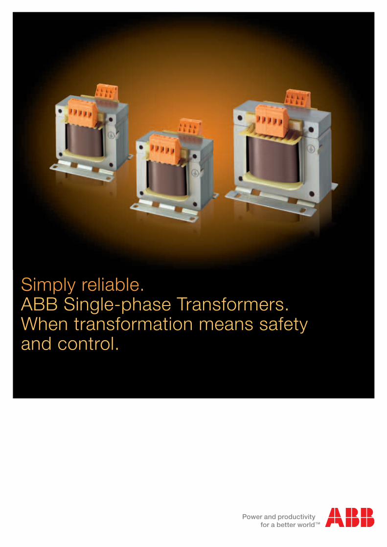
ControlTM-C control series
Primary 230-400VSecondary 12-24V
Primary 230-400VSecondary 115-230V
Standards IEC EN 61558-2-2UL506, CSA C22-2-N66
2
The operational control of machines and automatic systems is performed by auxiliary (or control) circuits. Because of this function, these circuits must satisfy increasingly complex requirements. As a result, they must be particularly reliable, both in terms of function and of safety against direct and indirect contacts.
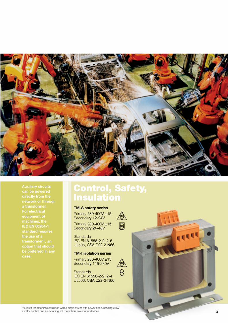
Control, Safety, InsulationTM-S safety series
Primary 230-400V ±15Secondary 12-24V
Primary 230-400V ±15Secondary 24-48V
Standards IEC EN 61558-2-2, 2-6UL506, CSA C22-2-N66
TM-I isolation series
Primary 230-400V ±15Secondary 115-230V
Standards IEC EN 61558-2-2, 2-4UL506, CSA C22-2-N66
3
InsulationTM-S safety series
Primary 230-400V ±15Secondary 12-24V
Primary 230-400V ±15Secondary 24-48V
Standards IEC EN 61558-2-2, 2-6UL506, CSA C22-2-N66
TM-I isolation series
Primary 230-400V ±15Secondary 115-230V
Standards IEC EN 61558-2-2, 2-4UL506, CSA C22-2-N66
3
Auxiliary circuits can be powered directly from the network or through a transformer. For electrical equipment of machines, the IEC EN 60204-1 standard requires the use of a transformer(1), an option that should be preferred in any case.
(1) Except for machines equipped with a single motor with power not exceeding 3 kW and for control circuits including not more than two control devices.
Choosing an ABB transformerChoosing experience. ABB stands for sure quality and effective results.
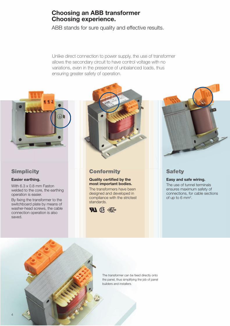
Unlike direct connection to power supply, the use of transformer allows the secondary circuit to have control voltage with no variations, even in the presence of unbalanced loads, thus ensuring greater safety of operation.
Simplicity Easier earthing.
With 6.3 x 0.8 mm Faston welded to the core, the earthing operation is easier. By fixing the transformer to the switchboard plate by means of washer-head screws, the cable connection operation is also saved.
SafetyEasy and safe wiring. The use of tunnel terminals ensures maximum safety of connections, for cable sections of up to 6 mm2.
ConformityQuality certified by the most important bodies. The transformers have been designed and developed in compliance with the strictest standards.
The transformer can be fixed directly onto the panel, thus simplifying the job of panel builders and installers.
4
5
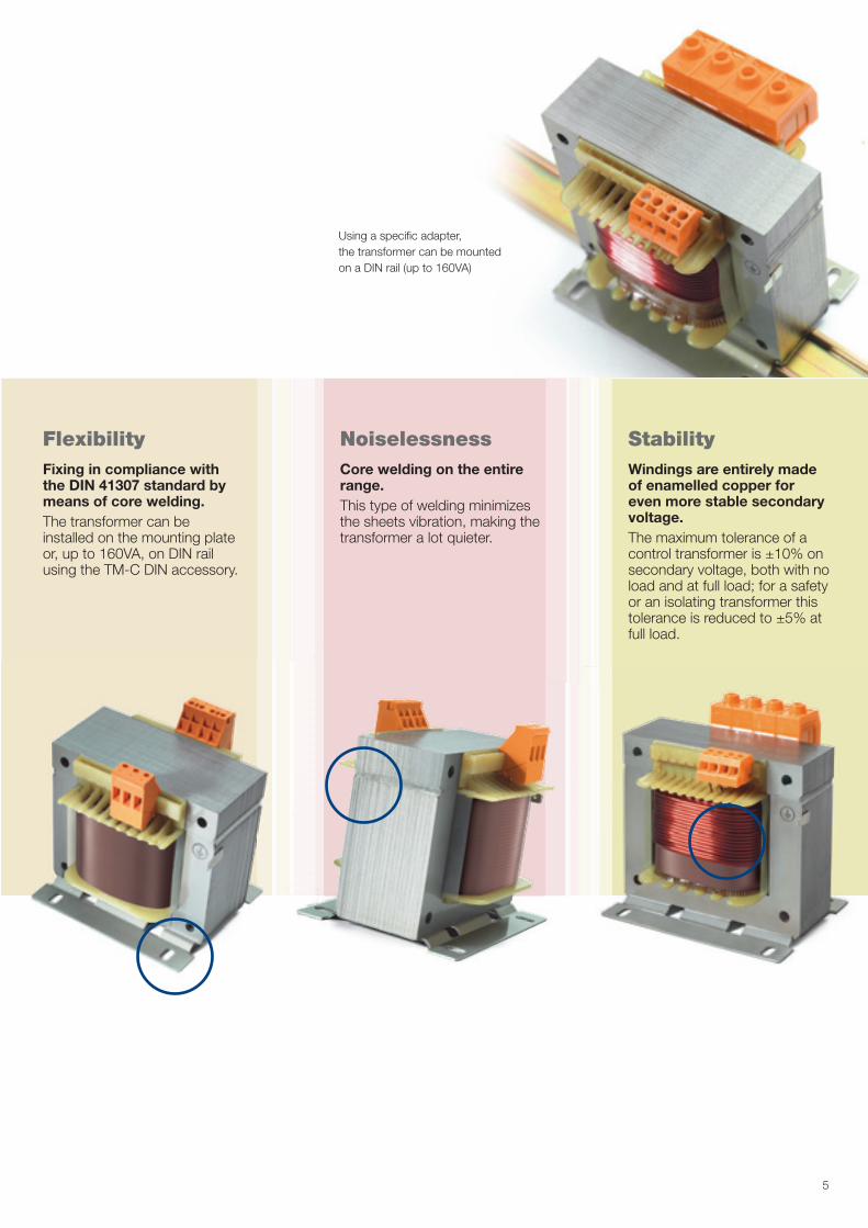
FlexibilityFixing in compliance with the DIN 41307 standard by means of core welding. The transformer can be installed on the mounting plate or, up to 160VA, on DIN rail using the TM-C DIN accessory.
NoiselessnessCore welding on the entire range. This type of welding minimizes the sheets vibration, making the transformer a lot quieter.
StabilityWindings are entirely made of enamelled copper for even more stable secondary voltage. The maximum tolerance of a control transformer is ±10% on secondary voltage, both with no load and at full load; for a safety or an isolating transformer this tolerance is reduced to ±5% at full load.
Using a specific adapter, the transformer can be mounted on a DIN rail (up to 160VA)
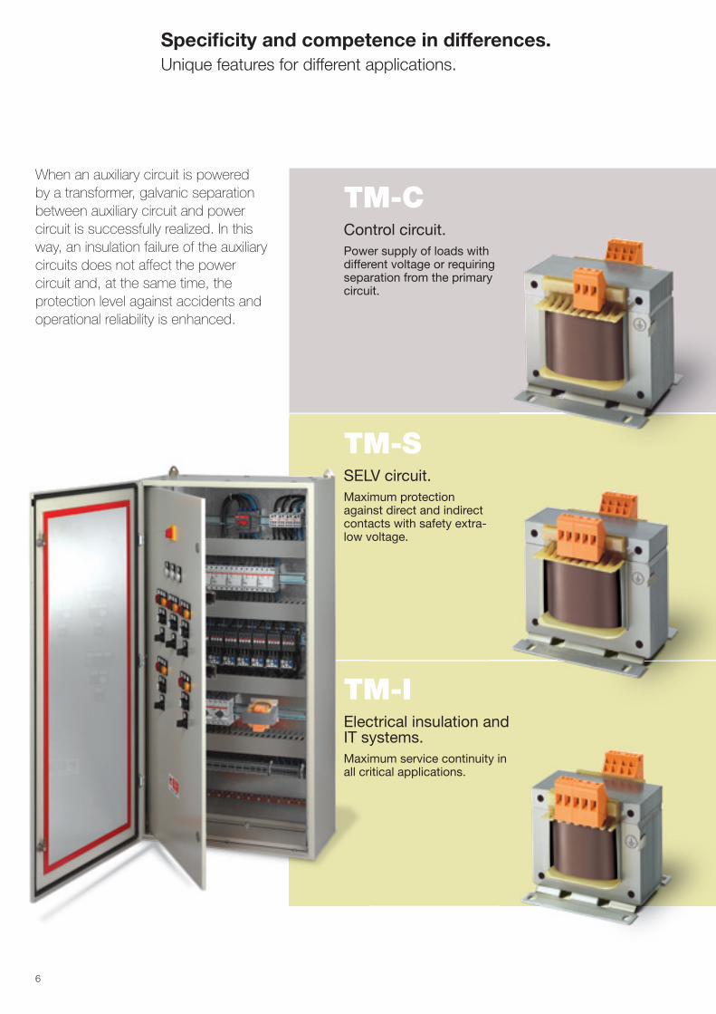
TM-CControl circuit. Power supply of loads with different voltage or requiring separation from the primary circuit.
Specificity and competence in differences.Unique features for different applications.
When an auxiliary circuit is powered by a transformer, galvanic separation between auxiliary circuit and power circuit is successfully realized. In this way, an insulation failure of the auxiliary circuits does not affect the power circuit and, at the same time, the protection level against accidents and operational reliability is enhanced.
6
TM-SSELV circuit. Maximum protection against direct and indirect contacts with safety extra-low voltage.
TM-IElectrical insulation and IT systems. Maximum service continuity in all critical applications.
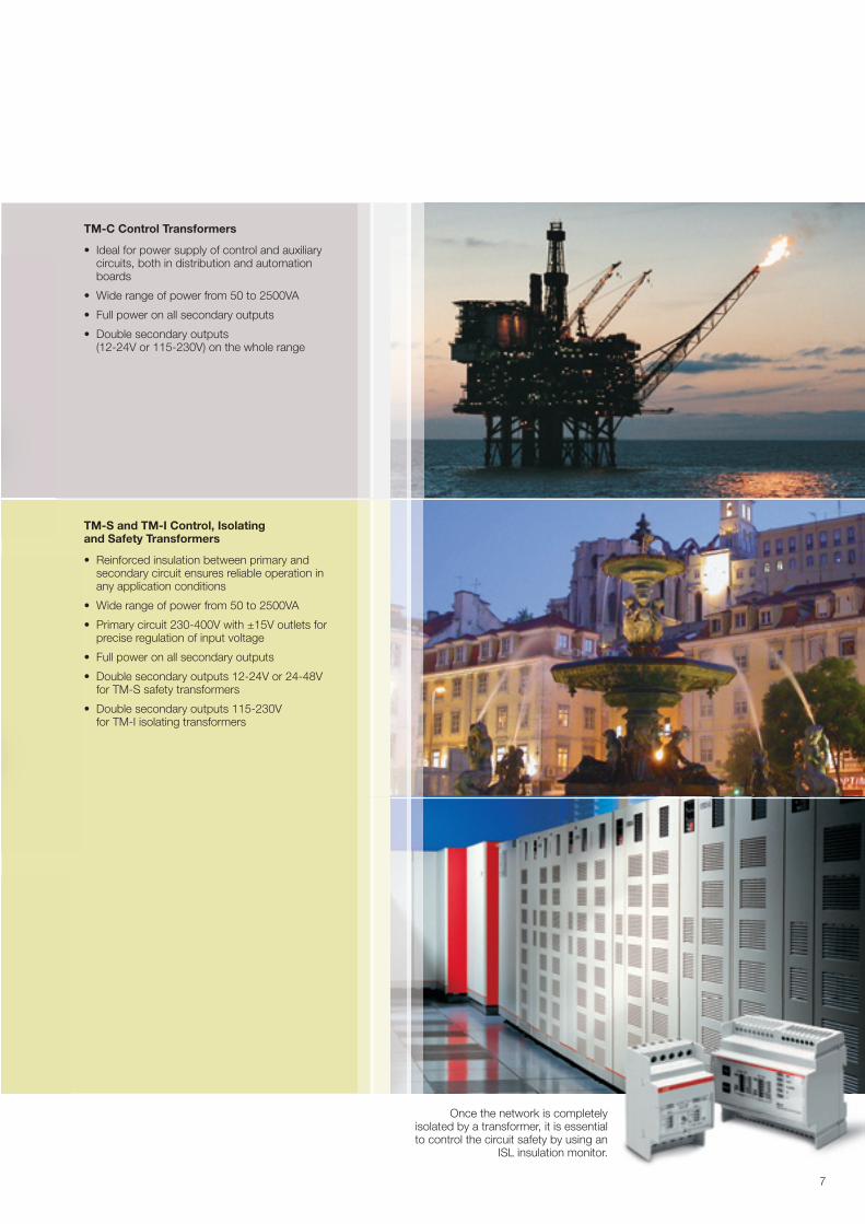
Once the network is completely isolated by a transformer, it is essential to control the circuit safety by using an
ISL insulation monitor.
TM-C Control Transformers
• Ideal for power supply of control and auxiliary circuits, both in distribution and automation boards
• Wide range of power from 50 to 2500VA
• Full power on all secondary outputs
• Double secondary outputs (12-24V or 115-230V) on the whole range
TM-S and TM-I Control, Isolating and Safety Transformers
• Reinforced insulation between primary and secondary circuit ensures reliable operation in any application conditions
• Wide range of power from 50 to 2500VA
• Primary circuit 230-400V with ±15V outlets for precise regulation of input voltage
• Full power on all secondary outputs
• Double secondary outputs 12-24V or 24-48V for TM-S safety transformers
• Double secondary outputs 115-230V for TM-I isolating transformers
�
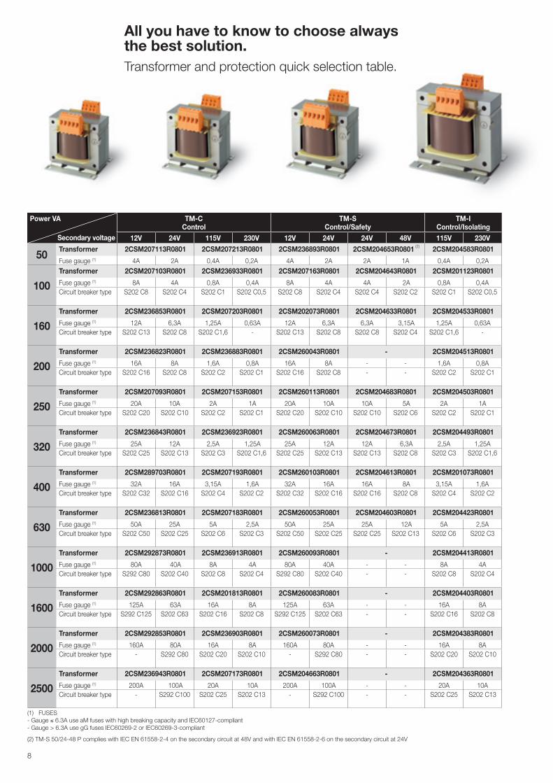
All you have to know to choose always the best solution. Transformer and protection quick selection table.
Power VA TM-C Control
TM-S Control/Safety
TM-I Control/Isolating
12V 24V 115V 230V 12V 24V 24V 48V 115V 230V
50Transformer 2CSM207113R0801 2CSM207213R0801 2CSM236893R0801 2CSM204653R0801 (2) 2CSM204583R0801
Fuse gauge (1) 4A 2A 0,4A 0,2A 4A 2A 2A 1A 0,4A 0,2A
100Transformer 2CSM207103R0801 2CSM236933R0801 2CSM207163R0801 2CSM204643R0801 2CSM201123R0801
Fuse gauge (1) 8A 4A 0,8A 0,4A 8A 4A 4A 2A 0,8A 0,4ACircuit breaker type S202 C8 S202 C4 S202 C1 S202 C0,5 S202 C8 S202 C4 S202 C4 S202 C2 S202 C1 S202 C0,5
160Transformer 2CSM236853R0801 2CSM207203R0801 2CSM202073R0801 2CSM204633R0801 2CSM204533R0801
Fuse gauge (1) 12A 6,3A 1,25A 0,63A 12A 6,3A 6,3A 3,15A 1,25A 0,63ACircuit breaker type S202 C13 S202 C8 S202 C1,6 - S202 C13 S202 C8 S202 C8 S202 C4 S202 C1,6 -
200Transformer 2CSM236823R0801 2CSM236883R0801 2CSM260043R0801 - 2CSM204513R0801
Fuse gauge (1) 16A 8A 1,6A 0,8A 16A 8A - - 1,6A 0,8ACircuit breaker type S202 C16 S202 C8 S202 C2 S202 C1 S202 C16 S202 C8 - - S202 C2 S202 C1
250Transformer 2CSM207093R0801 2CSM207153R0801 2CSM260113R0801 2CSM204683R0801 2CSM204503R0801
Fuse gauge (1) 20A 10A 2A 1A 20A 10A 10A 5A 2A 1ACircuit breaker type S202 C20 S202 C10 S202 C2 S202 C1 S202 C20 S202 C10 S202 C10 S202 C6 S202 C2 S202 C1
320Transformer 2CSM236843R0801 2CSM236923R0801 2CSM260063R0801 2CSM204673R0801 2CSM204493R0801
Fuse gauge (1) 25A 12A 2,5A 1,25A 25A 12A 12A 6,3A 2,5A 1,25ACircuit breaker type S202 C25 S202 C13 S202 C3 S202 C1,6 S202 C25 S202 C13 S202 C13 S202 C8 S202 C3 S202 C1,6
400Transformer 2CSM289703R0801 2CSM207193R0801 2CSM260103R0801 2CSM204613R0801 2CSM201073R0801
Fuse gauge (1) 32A 16A 3,15A 1,6A 32A 16A 16A 8A 3,15A 1,6ACircuit breaker type S202 C32 S202 C16 S202 C4 S202 C2 S202 C32 S202 C16 S202 C16 S202 C8 S202 C4 S202 C2
630Transformer 2CSM236813R0801 2CSM207183R0801 2CSM260053R0801 2CSM204603R0801 2CSM204423R0801
Fuse gauge (1) 50A 25A 5A 2,5A 50A 25A 25A 12A 5A 2,5ACircuit breaker type S202 C50 S202 C25 S202 C6 S202 C3 S202 C50 S202 C25 S202 C25 S202 C13 S202 C6 S202 C3
1000Transformer 2CSM292873R0801 2CSM236913R0801 2CSM260093R0801 - 2CSM204413R0801
Fuse gauge (1) 80A 40A 8A 4A 80A 40A - - 8A 4ACircuit breaker type S292 C80 S202 C40 S202 C8 S202 C4 S292 C80 S202 C40 - - S202 C8 S202 C4
1600Transformer 2CSM292863R0801 2CSM201813R0801 2CSM260083R0801 - 2CSM204403R0801
Fuse gauge (1) 125A 63A 16A 8A 125A 63A - - 16A 8ACircuit breaker type S292 C125 S202 C63 S202 C16 S202 C8 S292 C125 S202 C63 - - S202 C16 S202 C8
2000Transformer 2CSM292853R0801 2CSM236903R0801 2CSM260073R0801 - 2CSM204383R0801
Fuse gauge (1) 160A 80A 16A 8A 160A 80A - - 16A 8ACircuit breaker type - S292 C80 S202 C20 S202 C10 - S292 C80 - - S202 C20 S202 C10
2500Transformer 2CSM236943R0801 2CSM207173R0801 2CSM204663R0801 - 2CSM204363R0801
Fuse gauge (1) 200A 100A 20A 10A 200A 100A - - 20A 10ACircuit breaker type - S292 C100 S202 C25 S202 C13 - S292 C100 - - S202 C25 S202 C13
Secondary voltage
8
(1) FUSES - Gauge ≤ 6.3A use aM fuses with high breaking capacity and IEC6012�-compliant - Gauge > 6.3A use gG fuses IEC60269-2 or IEC60269-3-compliant
(2) TM-S 50/24-48 P complies with IEC EN 61558-2-4 on the secondary circuit at 48V and with IEC EN 61558-2-6 on the secondary circuit at 24V
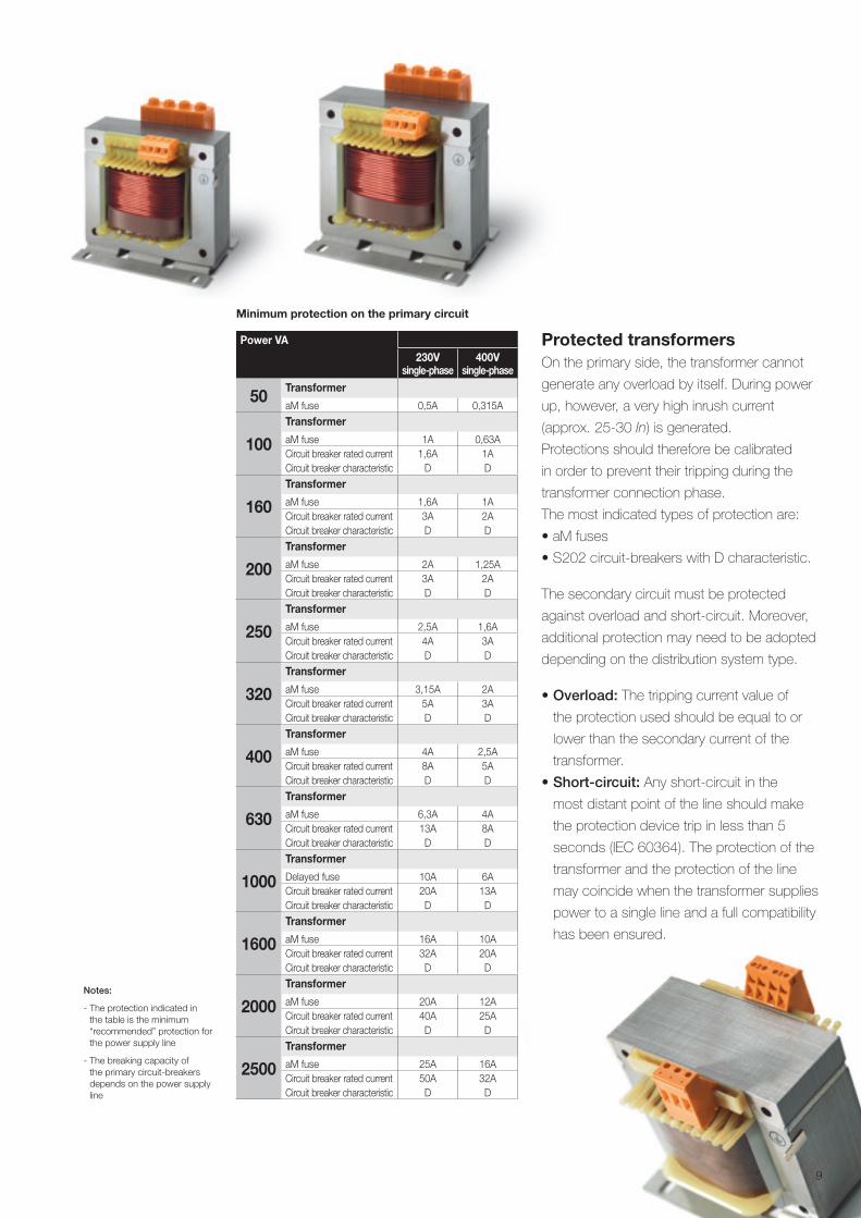
Protected transformers On the primary side, the transformer cannot
generate any overload by itself. During power
up, however, a very high inrush current
(approx. 25-30 In) is generated.
Protections should therefore be calibrated
in order to prevent their tripping during the
transformer connection phase.
The most indicated types of protection are:
• aM fuses
• S202 circuit-breakers with D characteristic.
The secondary circuit must be protected
against overload and short-circuit. Moreover,
additional protection may need to be adopted
depending on the distribution system type.
• Overload: The tripping current value of
the protection used should be equal to or
lower than the secondary current of the
transformer.
• Short-circuit: Any short-circuit in the
most distant point of the line should make
the protection device trip in less than 5
seconds (IEC 60364). The protection of the
transformer and the protection of the line
may coincide when the transformer supplies
power to a single line and a full compatibility
has been ensured.
Minimum protection on the primary circuit
Power VA230V
single-phase400V
single-phase
50Transformer
aM fuse 0,5A 0,315A
100Transformer
aM fuse 1A 0,63ACircuit breaker rated current 1,6A 1ACircuit breaker characteristic D D
160Transformer
aM fuse 1,6A 1ACircuit breaker rated current 3A 2ACircuit breaker characteristic D D
200Transformer
aM fuse 2A 1,25ACircuit breaker rated current 3A 2ACircuit breaker characteristic D D
250Transformer
aM fuse 2,5A 1,6ACircuit breaker rated current 4A 3ACircuit breaker characteristic D D
320Transformer
aM fuse 3,15A 2ACircuit breaker rated current 5A 3ACircuit breaker characteristic D D
400Transformer
aM fuse 4A 2,5ACircuit breaker rated current 8A 5ACircuit breaker characteristic D D
630Transformer
aM fuse 6,3A 4ACircuit breaker rated current 13A 8ACircuit breaker characteristic D D
1000Transformer
Delayed fuse 10A 6ACircuit breaker rated current 20A 13ACircuit breaker characteristic D D
1600Transformer
aM fuse 16A 10ACircuit breaker rated current 32A 20ACircuit breaker characteristic D D
2000Transformer
aM fuse 20A 12ACircuit breaker rated current 40A 25ACircuit breaker characteristic D D
2500Transformer
aM fuse 25A 16ACircuit breaker rated current 50A 32ACircuit breaker characteristic D D
Notes:
- The protection indicated in the table is the minimum “recommended” protection for the power supply line
- The breaking capacity of the primary circuit-breakers depends on the power supply line
9
With ABB theory turns into practice. Technical details. The concepts of single-phase transformers.
When choosing the voltage value for supplying power to control circuits, two aspects should be taken into consideration: operators safety and functional reliability of the circuits, which may depend on voltage drop. For the safety of operators, machines and systems, you need to ensure that any accidental earth contact in one or more points of the auxiliary circuits cannot cause any unwanted start of the machine or cannot prevent the stop of the machine.
Control Transformer
This transformer is intended for power supply of control circuits, i.e. checking, signalling, interlock, etc.
Isolating Transformer
An isolating transformer is a transformer where primary and secondary windings are electrically separated by a double or reinforced insulation, in order to minimize (in the secondary-side powered circuit) any risk due to simultaneous accidental contacts with the ground or with active parts or masses that can be energized in case of failure of the main insulation.
Safety Transformer
This is an isolating transformer intended for powering sa-fety extra-low voltage circuits (<50 V with no load). Any accidental contact on the secondary winding phases does not cause any danger to the operators.
Impregnation and tropicalization
ABB transformers are completely impregnated using a resin with insulation class F. This treatment improves the characteristics of the insula-tors used, making the transformer suitable for installation in severe environments, improves heat exchange by re-ducing transformer temperature, prevents moisture from penetrating into the windings and core, and minimizes vibrations and resulting noise.
Insulation classes
The durability of product insulation is affected by several factors and, if the insulating material electrically separates parts accessible for use and live parts, any alteration of its characteristics may generate risks for user safety. The standards lay down maximum temperature limits for transformer windings according to the insulation class. The ABB transformers are made with class B materials. The maximum room temperature to be considered is in-dicated in the transformer nameplate data.
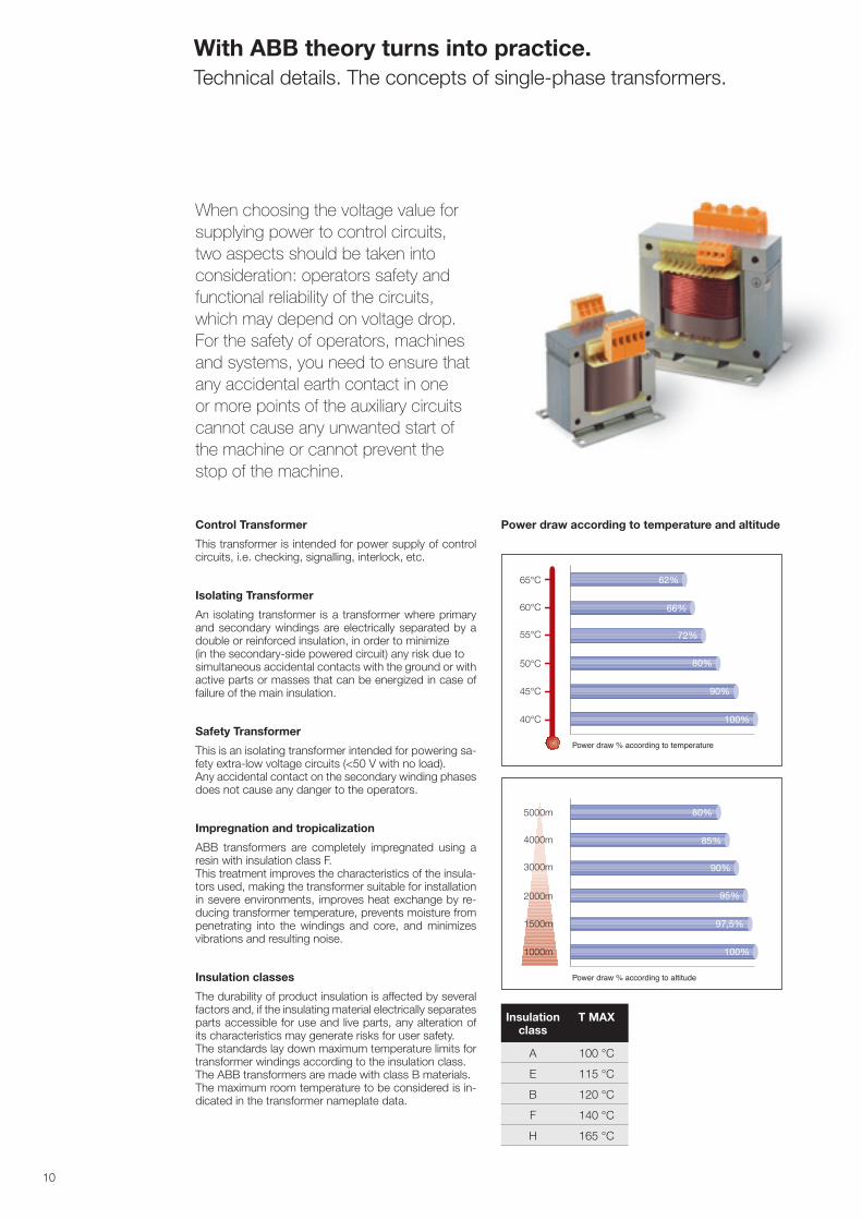
Power draw according to temperature and altitude
10
62%
66%
72%
80%
90%
100%
Power draw % according to temperature
80%
85%
90%
95%
97,5%
100%
Power draw % according to altitude
5000m
4000m
3000m
2000m
1500m
1000m
62%
66%
72%
80%
90%
100%
Power draw % according to temperature
80%
85%
90%
95%
97,5%
100%
Power draw % according to altitude
5000m
4000m
3000m
2000m
1500m
1000m
Insulation class
T MAX
A 100 °C
E 115 °C
B 120 °C
F 140 °C
H 165 °C
1,0 Pn 1,1 Pn 1,2 Pn 1,3 Pn 1,4 Pn 1,5 Pn
0
10
20
30
40
50
60
�0
80
90
100
110
120
130
140
150
160
1�0
180
190
Admissible overload
min
utes
50%
60%
70%
80%
90%
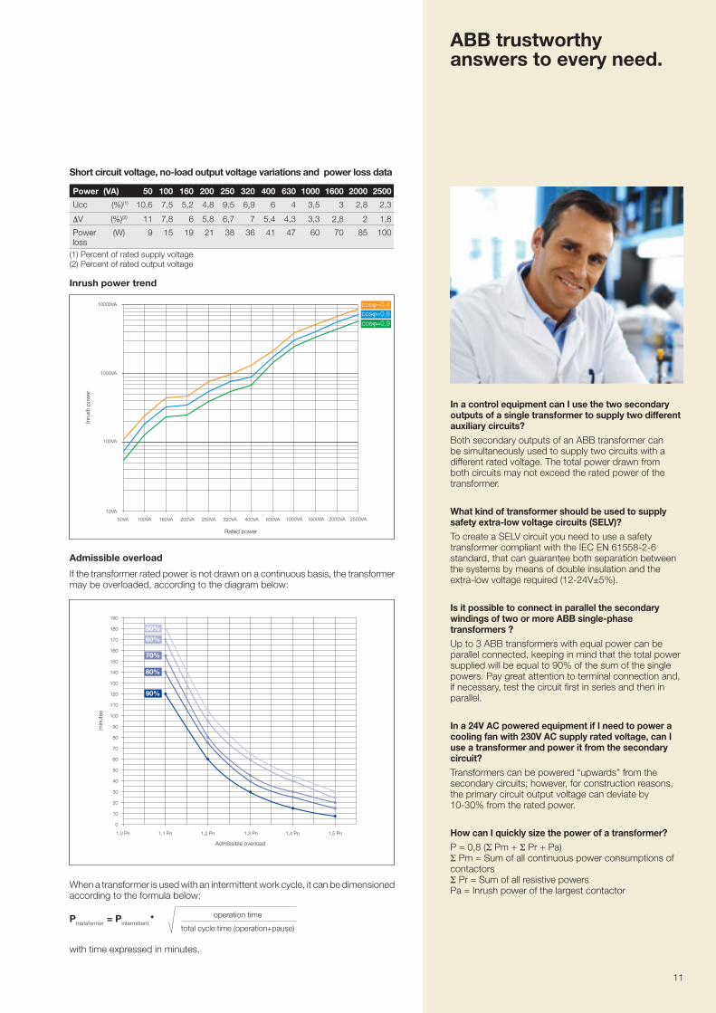
Admissible overload
If the transformer rated power is not drawn on a continuous basis, the transformer may be overloaded, according to the diagram below:
In a control equipment can I use the two secondary outputs of a single transformer to supply two different auxiliary circuits? Both secondary outputs of an ABB transformer can be simultaneously used to supply two circuits with a different rated voltage. The total power drawn from both circuits may not exceed the rated power of the transformer.
What kind of transformer should be used to supply safety extra-low voltage circuits (SELV)? To create a SELV circuit you need to use a safety transformer compliant with the IEC EN 61558-2-6 standard, that can guarantee both separation between the systems by means of double insulation and the extra-low voltage required (12-24V±5%).
Is it possible to connect in parallel the secondary windings of two or more ABB single-phase transformers ? Up to 3 ABB transformers with equal power can be parallel connected, keeping in mind that the total power supplied will be equal to 90% of the sum of the single powers. Pay great attention to terminal connection and, if necessary, test the circuit first in series and then in parallel.
In a 24V AC powered equipment if I need to power a cooling fan with 230V AC supply rated voltage, can I use a transformer and power it from the secondary circuit? Transformers can be powered “upwards” from the secondary circuits; however, for construction reasons, the primary circuit output voltage can deviate by 10-30% from the rated power.
How can I quickly size the power of a transformer? P = 0,8 (Σ Pm + Σ Pr + Pa)Σ Pm = Sum of all continuous power consumptions of contactors Σ Pr = Sum of all resistive powers Pa = Inrush power of the largest contactor
Ptransformer = Pintermittent *operation time
total cycle time (operation+pause)
When a transformer is used with an intermittent work cycle, it can be dimensioned according to the formula below:
with time expressed in minutes.
Inrush power trend
Rated power
2500VA2000VA1600VA1000VA630VA400VA320VA250VA200VA160VA100VA50VA
10000VA
1000VA
100VA
10VA
Inru
sh p
ower
ABB trustworthy answers to every need.
Short circuit voltage, no-load output voltage variations and power loss data
Power (VA) 50 100 160 200 250 320 400 630 1000 1600 2000 2500
Ucc (%)(1) 10,6 �,5 5,2 4,8 9,5 6,9 6 4 3,5 3 2,8 2,3
∆V (%)(2) 11 �,8 6 5,8 6,� � 5,4 4,3 3,3 2,8 2 1,8
Power loss
(W) 9 15 19 21 38 36 41 4� 60 �0 85 100
(1) Percent of rated supply voltage(2) Percent of rated output voltage
11
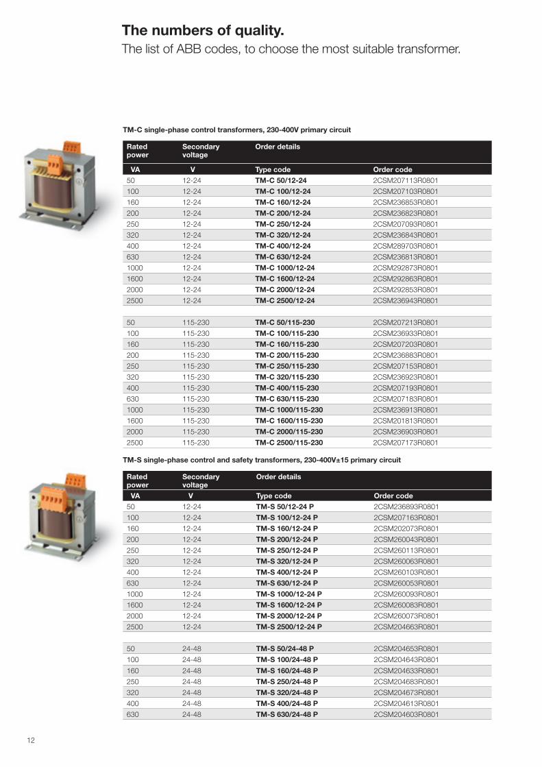
The numbers of quality. The list of ABB codes, to choose the most suitable transformer.
TM-C single-phase control transformers, 230-400V primary circuit
Rated power
Secondary voltage
Order details
VA V Type code Order code
50 12-24 TM-C 50/12-24 2CSM20�113R0801
100 12-24 TM-C 100/12-24 2CSM20�103R0801
160 12-24 TM-C 160/12-24 2CSM236853R0801
200 12-24 TM-C 200/12-24 2CSM236823R0801
250 12-24 TM-C 250/12-24 2CSM20�093R0801
320 12-24 TM-C 320/12-24 2CSM236843R0801
400 12-24 TM-C 400/12-24 2CSM289�03R0801
630 12-24 TM-C 630/12-24 2CSM236813R0801
1000 12-24 TM-C 1000/12-24 2CSM2928�3R0801
1600 12-24 TM-C 1600/12-24 2CSM292863R0801
2000 12-24 TM-C 2000/12-24 2CSM292853R0801
2500 12-24 TM-C 2500/12-24 2CSM236943R0801
50 115-230 TM-C 50/115-230 2CSM20�213R0801
100 115-230 TM-C 100/115-230 2CSM236933R0801
160 115-230 TM-C 160/115-230 2CSM20�203R0801
200 115-230 TM-C 200/115-230 2CSM236883R0801
250 115-230 TM-C 250/115-230 2CSM20�153R0801
320 115-230 TM-C 320/115-230 2CSM236923R0801
400 115-230 TM-C 400/115-230 2CSM20�193R0801
630 115-230 TM-C 630/115-230 2CSM20�183R0801
1000 115-230 TM-C 1000/115-230 2CSM236913R0801
1600 115-230 TM-C 1600/115-230 2CSM201813R0801
2000 115-230 TM-C 2000/115-230 2CSM236903R0801
2500 115-230 TM-C 2500/115-230 2CSM20�1�3R0801
Rated power
Secondary voltage
Order details
VA V Type code Order code
50 12-24 TM-S 50/12-24 P 2CSM236893R0801
100 12-24 TM-S 100/12-24 P 2CSM20�163R0801
160 12-24 TM-S 160/12-24 P 2CSM2020�3R0801
200 12-24 TM-S 200/12-24 P 2CSM260043R0801
250 12-24 TM-S 250/12-24 P 2CSM260113R0801
320 12-24 TM-S 320/12-24 P 2CSM260063R0801
400 12-24 TM-S 400/12-24 P 2CSM260103R0801
630 12-24 TM-S 630/12-24 P 2CSM260053R0801
1000 12-24 TM-S 1000/12-24 P 2CSM260093R0801
1600 12-24 TM-S 1600/12-24 P 2CSM260083R0801
2000 12-24 TM-S 2000/12-24 P 2CSM2600�3R0801
2500 12-24 TM-S 2500/12-24 P 2CSM204663R0801
50 24-48 TM-S 50/24-48 P 2CSM204653R0801
100 24-48 TM-S 100/24-48 P 2CSM204643R0801
160 24-48 TM-S 160/24-48 P 2CSM204633R0801
250 24-48 TM-S 250/24-48 P 2CSM204683R0801
320 24-48 TM-S 320/24-48 P 2CSM2046�3R0801
400 24-48 TM-S 400/24-48 P 2CSM204613R0801
630 24-48 TM-S 630/24-48 P 2CSM204603R0801
TM-S single-phase control and safety transformers, 230-400V±15 primary circuit
12
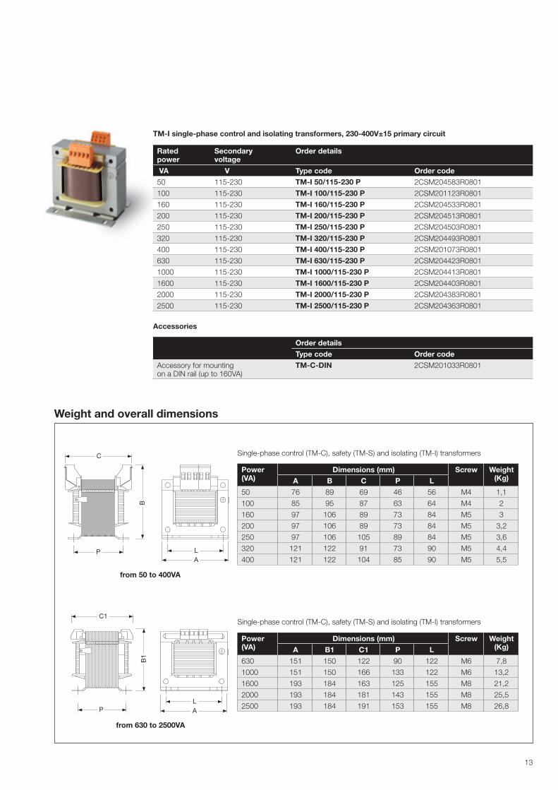
TM-I single-phase control and isolating transformers, 230-400V±15 primary circuit
Rated power
Secondary voltage
Order details
VA V Type code Order code
50 115-230 TM-I 50/115-230 P 2CSM204583R0801
100 115-230 TM-I 100/115-230 P 2CSM201123R0801
160 115-230 TM-I 160/115-230 P 2CSM204533R0801
200 115-230 TM-I 200/115-230 P 2CSM204513R0801
250 115-230 TM-I 250/115-230 P 2CSM204503R0801
320 115-230 TM-I 320/115-230 P 2CSM204493R0801
400 115-230 TM-I 400/115-230 P 2CSM2010�3R0801
630 115-230 TM-I 630/115-230 P 2CSM204423R0801
1000 115-230 TM-I 1000/115-230 P 2CSM204413R0801
1600 115-230 TM-I 1600/115-230 P 2CSM204403R0801
2000 115-230 TM-I 2000/115-230 P 2CSM204383R0801
2500 115-230 TM-I 2500/115-230 P 2CSM204363R0801
Accessories
Order detailsType code Order code
Accessory for mounting on a DIN rail (up to 160VA)
TM-C-DIN 2CSM201033R0801
Power (VA)
Dimensions (mm) Screw Weight (Kg) A B C P L
50 �6 89 69 46 56 M4 1,1
100 85 95 8� 63 64 M4 2
160 9� 106 89 �3 84 M5 3
200 9� 106 89 �3 84 M5 3,2
250 9� 106 105 89 84 M5 3,6
320 121 122 91 �3 90 M5 4,4
400 121 122 104 85 90 M5 5,5
Single-phase control (TM-C), safety (TM-S) and isolating (TM-I) transformers
Power (VA)
Dimensions (mm) Screw Weight (Kg) A B1 C1 P L
630 151 150 122 90 122 M6 �,8
1000 151 150 166 133 122 M6 13,2
1600 193 184 163 125 155 M8 21,2
2000 193 184 181 143 155 M8 25,5
2500 193 184 191 153 155 M8 26,8
Single-phase control (TM-C), safety (TM-S) and isolating (TM-I) transformers
from 50 to 400VA
from 630 to 2500VA
Weight and overall dimensions
13
C
P LA
B
C1
P
B1
LA
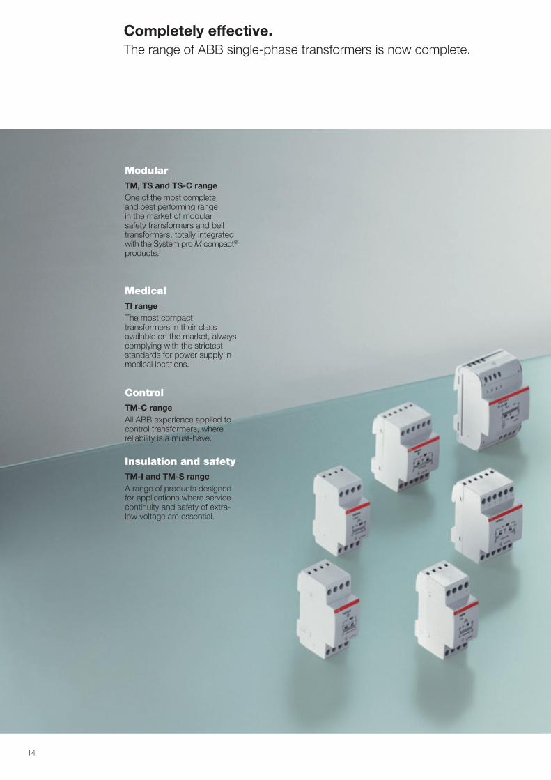
Completely effective. The range of ABB single-phase transformers is now complete.
14
Modular TM, TS and TS-C range One of the most complete and best performing range in the market of modular safety transformers and bell transformers, totally integrated with the System pro M compact® products.
MedicalTI range The most compact transformers in their class available on the market, always complying with the strictest standards for power supply in medical locations.
ControlTM-C range All ABB experience applied to control transformers, where reliability is a must-have.
Insulation and safety TM-I and TM-S range A range of products designed for applications where service continuity and safety of extra-low voltage are essential.
15
Contacts
2CS
C44
6005
B02
02 -
09/
2012Data and images are not binding. Depending on technical
development and the products, we reserve the right to modify the content of this document without notice.
Copyright 2012 ABB. All right reserved.
ABB SACEA division of ABB S.p.A.Modular DevicesViale dell’Industria, 1820010 Vittuone (MI) - ItalyTel.: +39 02 9034 1Fax: +39 02 9034 7609
www.abb.com