ABB Schalt– und Steuerungstechnik PC 331/Issued: 11.98 1–1 1 Installation _____ Installation of...
54
Operating Manual ABB Procontic Programming System 907 PC 331 Programming and Test Software System-Specific Part ABB Procontic CS31 Advant Controller 31 ABB Schalt– und Steuerungstechnik
Transcript of ABB Schalt– und Steuerungstechnik PC 331/Issued: 11.98 1–1 1 Installation _____ Installation of...
Operating Manual ABB ProconticProgramming System
907 PC 331Programming and Test SoftwareSystem-Specific PartABB Procontic CS31Advant Controller 31
ABB Schalt–und Steuerungstechnik


0–1907 PC 331/Issued: 11.98
Preface
____________________________________________________________________________________________
Notes for the user
All commands entered by the user are shown in italics,keys are shown as <Key> and screen displays, e.g. in-structions, appear in bold.
In the same way, you can use the left mouse key for the<Enter key> and the right mouse key for the <space bar>.For yes/no enquiries, you can use the left mouse key foryes and the right one for no.
Main menu: The selection of a main menu point is re-leased or defined every time the <right mouse key> ispressed. The selected sub–menu point is carried outwhen the <left mouse key> is pressed.
Key combinations:<key>–key or <key>–key–key:In this case, press the first key and hold it down. At thesame time, press the following keys.Example 1: <Alt>–2Press the <Alt> key and hold it down; at the same time,press the <2> key.Example 2: <Ctrl>–K–WPress the <Ctrl> key and hold it down; at the same time,press the keys <K> and <W> in turn.
Calling up online commands with hotkeysHotkeys are used to rapidly select functions which can al-ternatively be executed via pop–up menus. E.g. <Alt>–Sfor ”Start the PLC” (see Section 2, Work aid, ”ONLINEcommands”).
Selecting menu points in the pop–up menusRapid selection: by entering the high-lighted letters of themenu line; cursor positioning with <arrow key up> and<down> or the mouse not necessary.
Keyboards
The designations of certain keys on keyboards with Ger-man, English or American character sets differ. The fol-lowing table shows the differences:
German character set English/Americancharacter set
<Strg> <Ctrl><Einfg> <Ins><Entf> oder <Lösch> <Del><Bild ▲ > <PgUp><Bild ▼ > <PgDn><Pos 1> <Home><Ende> <End><WR> <Return><Tab. rechts> <RTAB><Tab. links> <LTAB><▲> <Shift>
The <Enter key> is used in this document. Other standarddesignations for this key are <Enter>, <Return>, <CR>and <WR>.
Abbreviations
AC31 Advant Controller 31AWP User programIL Instruction listFBD Function block diagramLD Ladder diagramPLC Programmable (logic) controllerCE Connection element<CR> Carriage Return or Enter, ReturnZE Central unit

0–2 907 PC 331/Issued: 11.98
0–3907 PC 331/Issued: 11.98
Contents
____________________________________________________________________________________________
1 Installation 1–1. . . . . . . . . . . . . . . . . . . . 1.1 Installing programming software
on the PC 1–2. . . . . . . . . . . . . . . . . . . . . . . . . 1.1.1 Manual installation 1–3. . . . . . . . . . . . . . . . . 1.2 Start programming software 1–5. . . . . . . . .
2 Notes on programming 2–1. . . . . . . . . . . 2.1 Connectable programming and
service devices 2–1. . . . . . . . . . . . . . . . . . . . 2.2 Programming and
test software 907 PC 331 2–2. . . . . . . . . . . 2.3 Programming 2–2. . . . . . . . . . . . . . . . . . . . . 2.3.1 Procedure for creating a program 2–2. . . . 2.3.2 Entering/changing a program 2–2. . . . . . . . 2.4 Saving a program
in the Flash EPROM 2–3. . . . . . . . . . . . . . . 2.4.1 Program: RAM ––> Flash EPROM 2–3. . . 2.4.2 Program: Flash EPROM ––> RAM 2–3. . . 2.4.3 Commissioning phase 2–3. . . . . . . . . . . . . . 2.5 Special instructions 2–4. . . . . . . . . . . . . . . . 2.5.1 System constants with
ABB Procontic CS31,Advant Controller 31 2–4. . . . . . . . . . . . . . .
2.5.2 Error diagnosis withABB Procontic CS31,Advant Controller 31 2–6. . . . . . . . . . . . . . .
2.5.3 Intermediate flag, updating 2–6. . . . . . . . .
3 Configuration 3–1. . . . . . . . . . . . . . . . . . . . 3.1 Project management 3–1. . . . . . . . . . . . . . .
4 ONLINE 4–1. . . . . . . . . . . . . . . . . . . . . . . . . 4.1 PLC communication 4–1. . . . . . . . . . . . . . . . 4.1.1 PLC communication 1 4–1. . . . . . . . . . . . . . 4.1.2 PLC communication 2 4–4. . . . . . . . . . . . . . 4.1.3 PLC communication 3 4–5. . . . . . . . . . . . . . 4.1.4 PLC communication from FBD/LD
and extended IL 4–6. . . . . . . . . . . . . . . . . . . 4.2 Test 4–10. . . . . . . . . . . . . . . . . . . . . . . . . . . . . .
5 ”Compare” program 5–1. . . . . . . . . . . . . .

0–4 907 PC 331/Issued: 11.98
1–1907 PC 331/Issued: 11.98
1 Installation
____________________________________________________________________________________________
Installation of the programming and test software 907 PC331 under the MS–DOS operating system is describedbelow step by step. If you are still not familiar with someMS–DOS terms, please look them up in your computer’s”MS–DOS operating system” manual.
The installation program creates the following directorystructure under MS–DOS:
C:\ ABB–SPS AC31 PROJEKTBIB
Notes
At least 10 MBytes memory space must be free on thehard disk for the installation. Insufficient memory spaceis indicated by the installation program by way of an ap-propriate message. In addition, at least 500 kB usermemory is required. The DOS command CHKDSK givesyou details about the size of the free user memory.
The entries for FILES and BUFFERS in the CON-FIG.SYS file are checked by the installation program and,if necessary, are adjusted to the values required for oper-ating 907 PC 331:
FILES=25BUFFERS=25
1–2 907 PC 331/Issued: 11.98
1.1 Installing programming software on the PC
The programming software 907 PC 331 consists of 2 diskettes. If a version of 907 PC 331 already exists on your PC,please first read the instructions at the end of this page.Insert diskette 1 into drive A. Enter the following instruction:
A: INSTALL <Enter key>
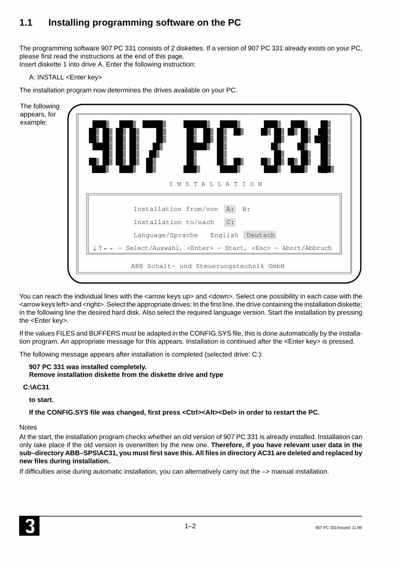
The installation program now determines the drives available on your PC.
Installation from/von A: B:
Installation to/nach C:
ABB Schalt– und Steuerungstechnik GmbH
– Select/Auswahl, <Enter> – Start, <Esc> – Abort/Abbruch
I N S T A L L A T I O N
Language/Sprache English Deutsch
The followingappears, forexample:
You can reach the individual lines with the <arrow keys up> and <down>. Select one possibility in each case with the<arrow keys left> and <right>. Select the appropriate drives: In the first line, the drive containing the installation diskette;in the following line the desired hard disk. Also select the required language version. Start the installation by pressingthe <Enter key>.
If the values FILES and BUFFERS must be adapted in the CONFIG.SYS file, this is done automatically by the installa-tion program. An appropriate message for this appears. Installation is continued after the <Enter key> is pressed.
The following message appears after installation is completed (selected drive: C:):
907 PC 331 was installed completely.Remove installation diskette from the diskette drive and type
C:\AC31
to start.
If the CONFIG.SYS file was changed, first press <Ctrl><Alt><Del> in order to restart the PC.
NotesAt the start, the installation program checks whether an old version of 907 PC 331 is already installed. Installation canonly take place if the old version is overwritten by the new one. Therefore, if you have relevant user data in thesub–directory ABB–SPS\AC31, you must first save this. All files in directory AC31 are deleted and replaced bynew files during installation.
If difficulties arise during automatic installation, you can alternatively carry out the –> manual installation.
1–3907 PC 331/Issued: 11.98
Notes on an update installation:
If you want to execute an Update Installation you must update your library.
Start the programming software as described under ”1.2. Starting the programming software” and choose ”Library”,”Read Manufacturer Library”. In order to update your SER90 library, enter ”NEU” (if you want to work with the Ger-man version) resp. ”NEW” (if you want to work with the English version). In order to update your SER50 library, enter”SER50NEU” (if you want to work with the German version) resp. ”SER50NEW” (if you want to work with the Englishversion). Please observe, that the library to be updated (AC31 or SER50) is entered in the project data.The existing library is now updated. Your user CEs will be conserved.
1.1.1 Manual installation
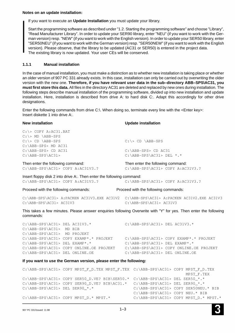
In the case of manual installation, you must make a distinction as to whether new installation is taking place or whetheran older version of 907 PC 331 already exists. In this case, installation can only be carried out by overwriting the olderversion with the new one. Therefore, if you have relevant user data in the sub–directory ABB–SPS\AC31, youmust first store this data. All files in the directory AC31 are deleted and replaced by new ones during installation. Thefollowing steps describe manual installation of the programming software, divided up into new installation and updateinstallation. Here, installation is described from drive A: to hard disk C:. Adapt this accordingly for other drivedesignations.
Enter the following commands from drive C:\. When doing so, terminate every line with the <Enter key>:Insert diskette 1 into drive A:.
New installation Update installation
C:\> COPY A:AC31.BATC:\> MD \ABB–SPSC:\> CD \ABB–SPS C:\> CD \ABB–SPSC:\ABB–SPS> MD AC31C:\ABB–SPS> CD AC31 C:\ABB–SPS> CD AC31C:\ABB–SPS\AC31> C:\ABB–SPS\AC31> DEL *.*
Then enter the following command: Then enter the following command:C:\ABB–SPS\AC31> COPY A:AC31V3.? C:\ABB–SPS\AC31> COPY A:AC31V3.?
Insert floppy disk 2 into drive A:. Then enter the following command:C:\ABB–SPS\AC31> COPY A:AC31V3.? C:\ABB–SPS\AC31> COPY A:AC31V3.?
Proceed with the following commands: Proceed with the following commands:
C:\ABB–SPS\AC31> A:PACKEN AC31V3.EXE AC31V2 C:\ABB–SPS\AC31> A:PACKEN AC31V2.EXE AC31V3C:\ABB–SPS\AC31> AC31V3 C:\ABB–SPS\AC31> AC31V3
This takes a few minutes. Please answer enquiries following Overwrite with ”Y” for yes. Then enter the followingcommands:
C:\ABB–SPS\AC31> DEL AC31V3.* C:\ABB–SPS\AC31> DEL AC31V3.*C:\ABB–SPS\AC31> MD BIBC:\ABB–SPS\AC31> MD PROJEKTC:\ABB–SPS\AC31> COPY EXAMP*.* PROJEKT C:\ABB–SPS\AC31> COPY EXAMP*.* PROJEKTC:\ABB–SPS\AC31> DEL EXAMP*.* C:\ABB–SPS\AC31> DEL EXAMP*.*C:\ABB–SPS\AC31> COPY ONLINE.OE PROJEKT C:\ABB–SPS\AC31> COPY ONLINE.OE PROJEKTC:\ABB–SPS\AC31> DEL ONLINE.OE C:\ABB–SPS\AC31> DEL ONLINE.OE
If you want to use the German version, please enter the following:
C:\ABB–SPS\AC31> COPY MPST_F_D.TEX MPST_F.TEX C:\ABB–SPS\AC31> COPY MPST_F_D.TEX MPST_F.TEX
C:\ABB–SPS\AC31> COPY SER50_D.VE? BIB\SER50.* C:\ABB–SPS\AC31> DEL SER50_*.*C:\ABB–SPS\AC31> COPY SER90_D.VE? BIB\AC31.* C:\ABB–SPS\AC31> DEL SER90_*.*C:\ABB–SPS\AC31> DEL SER90_*.* C:\ABB–SPS\AC31> COPY SER50NEU.* BIB
C:\ABB–SPS\AC31> COPY NEU.* BIBC:\ABB–SPS\AC31> COPY MPST_D.* MPST.* C:\ABB–SPS\AC31> COPY MPST_D.* MPST.*
1–4 907 PC 331/Issued: 11.98
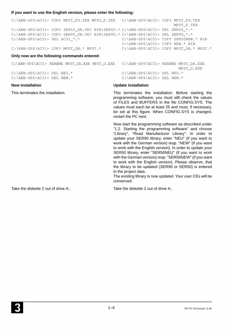
If you want to use the English version, please enter the following:
C:\ABB–SPS\AC31> COPY MPST_FG.TEX MPST_F.TEX C:\ABB–SPS\AC31> COPY MPST_FG.TEX MPST_F.TEX
C:\ABB–SPS\AC31> COPY SER50_GB.VE? BIB\SER50.* C:\ABB–SPS\AC31> DEL SER50_*.*C:\ABB–SPS\AC31> COPY SER90_GB.VE? BIB\SER90.* C:\ABB–SPS\AC31> DEL SER90_*.*C:\ABB–SPS\AC31> DEL AC31_*.* C:\ABB–SPS\AC31> COPY SER50NEW.* BIB
C:\ABB–SPS\AC31> COPY NEW.* BIBC:\ABB–SPS\AC31> COPY MPST_GB.* MPST.* C:\ABB–SPS\AC31> COPY MPST_GB.* MPST.*
Only now are the following commands entered:
C:\ABB–SPS\AC31> RENAME MPST_DA.EXE MPST_D.EXE C:\ABB–SPS\AC31> RENAME MPST_DA.EXE MPST_D.EXE
C:\ABB–SPS\AC31> DEL NEU.* C:\ABB–SPS\AC31> DEL NEU.*C:\ABB–SPS\AC31> DEL NEW.* C:\ABB–SPS\AC31> DEL NEW.*
New installation Update installation
This terminates the installation. This terminates the installation. Before starting theprogramming software, you must still check the valuesof FILES and BUFFERS in the file CONFIG.SYS. Thevalues must each be at least 25 and must, if necessary,be set at this figure. When CONFIG.SYS is changed,restart the PC next.
Now start the programming software as described under”1.2. Starting the programming software” and choose”Library”, ”Read Manufacturer Library”. In order toupdate your SER90 library, enter ”NEU” (if you want towork with the German version) resp. ”NEW” (if you wantto work with the English version). In order to update yourSER50 library, enter ”SER50NEU” (if you want to workwith the German version) resp. ”SER50NEW” (if you wantto work with the English version). Please observe, thatthe library to be updated (SER90 or SER50) is enteredin the project data.The existing library is now updated. Your user CEs will beconserved.
Take the diskette 2 out of drive A:. Take the diskette 2 out of drive A:.
1–5907 PC 331/Issued: 11.98
1.2 Start programming software
The following details apply to when you have installed the programming software under drive C:.
A batch file AC31.BAT was filed in the root directory during the installation. This allows you to start the programmingsoftware as follows:
C:\AC31 <Enter key>
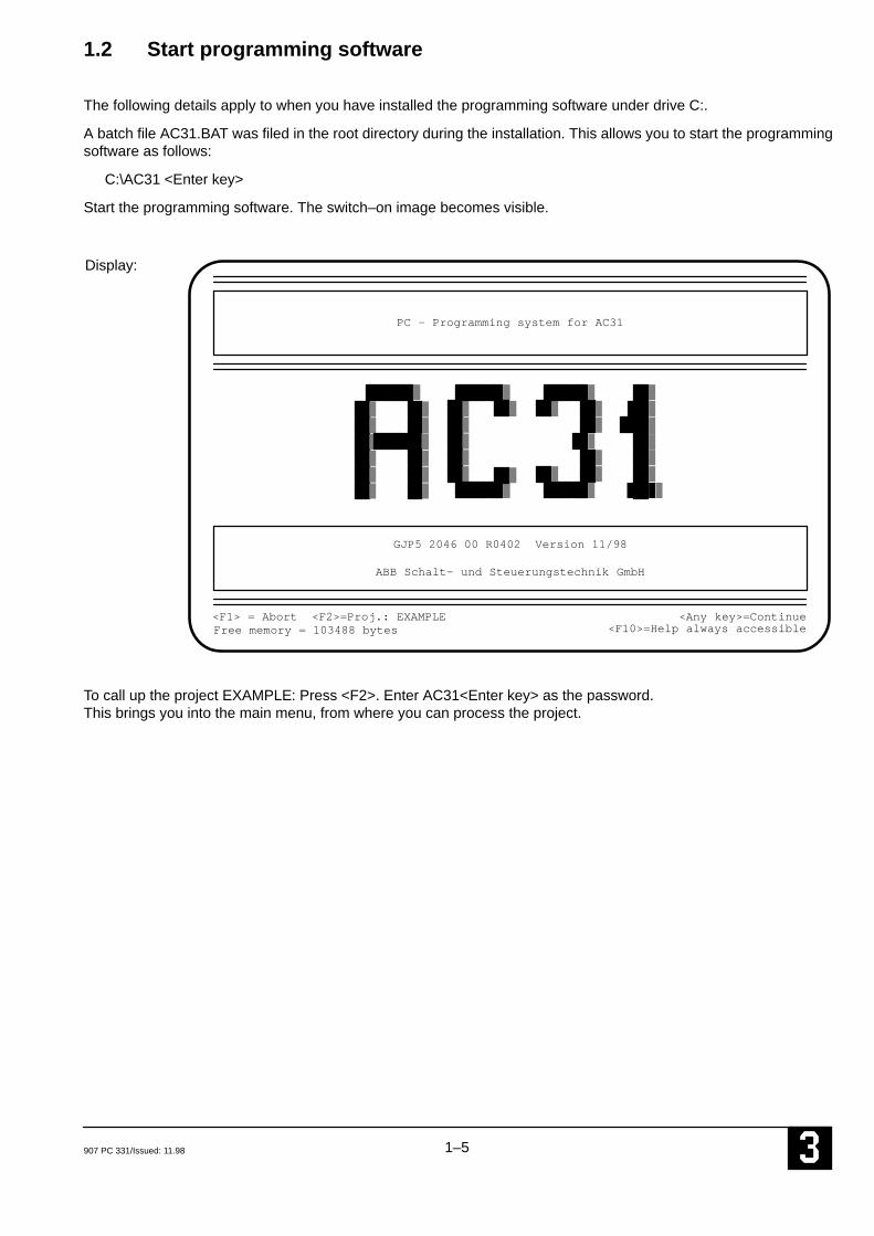
Start the programming software. The switch–on image becomes visible.
Display:
Free memory = 103488 bytes
PC – Programming system for AC31
ABB Schalt– und Steuerungstechnik GmbH
<F1> = Abort <F2>=Proj.: EXAMPLE <Any key>=Continue<F10>=Help always accessible
GJP5 2046 00 R0402 Version 11/98
To call up the project EXAMPLE: Press <F2>. Enter AC31<Enter key> as the password.This brings you into the main menu, from where you can process the project.

1–6 907 PC 331/Issued: 11.98

2–1907 PC 331/Issued: 11.98
2 Notes on programming
This section gives you an overview of the procedure for programming.
Service device TCZwith connection cable
Personal computer 07 PH 32 withABB Programming and test software
COM1 – Programming– MMC
COM2 – MMC (only 07 KT 92/93/94)
07 S
K 9
0
optionally toPC or TCZ
07 KT 94
Contents
2.1 Connectable programming andservice devices 2–1. . . . . . . . . . . . . . . . . . . . .
2.2 Programming and test software907 PC 331 2–2. . . . . . . . . . . . . . . . . . . . . . . . .
2.3 Programming 2–2. . . . . . . . . . . . . . . . . . . . . . Procedure for creating a program 2–2. . . . . . Entering/changing a program 2–2. . . . . . . . .
2.4 Saving a programin the Flash EPROM 2–3. . . . . . . . . . . . . . . .
2.5 Special instructions 2–4. . . . . . . . . . . . . . . .
2.1 Connectable programming and service devices
● Programming and test unit 07 PH 32
IBM compatible notebook PC for the ABB program-ming and test software.
Technical data:
– 80386SL processor
– Clock frequency 25 MHz
– 4 MByte RAM, can be extended up to 10 MByte
– Cache
– 84 MByte hard disk
– 3.5” floppy disk drive (1.44 MByte)
– 9.5” VGA monitor
– Battery operation for 3 hours
– Mains connection
– Mouse for rapid cursor control
– Second serial interface EIA RS–232
– Adaptor from 9–pole to 25–pole serial interface
– Dimensions 279 x 216 x 44 mm
– Weight ca. 2.7 kg
– Order No. for 07 PH 32: GJV 307 2104 R0002
● TCZ service device
This hand–held device is suitable for servicing and forsmall alterations, e.g. for changing variable address-es, flags, times and counters.
Programming language:– Instruction list (IL)
Technical data:
– 4 lines LED display with 16 characters each,5 x 7 dots
– Keyboard with 40 keys
– Dimensions 80 x 155 x 31 mm
– Weight ca. 400 g
– Order No. for TCZ: FPR3200002R1001

2–2 907 PC 331/Issued: 11.98
2.2 Programming and test software907 PC 331
Programming and test system for entering, testingand documenting programs.
Programming languages:– Function block diagram (FBD)– Instruction list (IL)– Ladder diagram (LD)
Features:
– Easy handling due to modern menu surface
– Menu selection with mouse or keyboard
– Operater guidance through instruction and helptexts
– Comments
– Symbolic variables
– ONLINE functionen such as status displaybit/word, breakpoint, forces
– Comprehensive program documentation in differ-ent formats
2.3 Programming
The PLC can be programmed in:
● Instruction list (IL)
● Function block diagram (FBD)
● Ladder diagram (LD)
● Sequential function chart (SFC)
Programming in the instruction list corresponds toDIN 19239. This DIN defines the structure of the instruc-tion and of the function block. The user program is en-tered into the PLC via the serial interface COM1 of thePLC.
When doing so, the ASCII characters from the instructionlist are directly transferred to the PLC. The programmingand test software, integrated in the PLC, translates the in-struction list during the transfer into another format. Thisformat (pseudo–code) is required for the processing. Thesoftware stores it in the user program RAM of the PLC.
The ASCII clear text interface revealed enables access tothe PLC with different user–friendly aids. These rangefrom the simple ASCII keyboard with digital display, be-yond the terminal, up to the user–friendly programmingand test system.
2.3.1 Procedure for creating a program
Creating an executable PLC program can be divided upas follows:
● Enter program, constants, system constants for oper-ating modes and system constant for cycle time intothe programming system
● Translate the program in the programming system
● Send program to the control system
● Send constants to the control system
● Save program in the Flash EPROM
● Start up and test the PLC program
For successful entering and altering of a program, pleasepay special attention to the following detailed descrip-tion.
2.3.2 Entering / changing a program
A PLC program can be entered or changed via the serialinterface COM1 of the PLC in the following statuses:
● ”Aborted” status
● ”Running” status
Entering / changing a program in the”aborted status”
In the ”aborted” status, program changes can be madewithout restriction. Before starting a changed program,the operating modes must be set so that all operandranges are initialized. It is thus ensured that all operandsand historical values are initialized to ”0”, and valuesstored by the battery back–up do not lead to malfunctions.
Procedure when entering / changing a program inthe ”aborted status”
● Enter program / changes into the programming sys-tem
● Translate program / changes in the programming sys-tem
● Send program / changes to the control system
● Save program in Flash EPROM
Note:For details really see also chapter 2.4 ”Program saving inthe Flash EPROM”.
Entering / changing a program in the”running” status
● Changes can be made to a running PLC program.
● When the changes are taken over, there is no PLCstandstill time.
● The user must exercise extreme care when makingchanges to a running PLC program, as the programchanges immediately influence the running processwithout the possibility of tests.Programming errors can have grave results.
2–3907 PC 331/Issued: 11.98
Permissible program changes
● Any program changes are permissible as long as nofunction blocks with historical values are affected.
● Function blocks with historical values may only beadded to or omitted at the program end.
● Any changes to indirect constants are permissible.This also includes changing the cycle time. If systemconstants are changed, chapter ”system constants”must be taken into account.
Forbidden program changes
● Deleting or adding to function blocks with historicalvalues within the PLC program is not allowed.
Procedure when changing a PLC program in the ”running” status
● Carry out changes in the programming system
● Translate changes in the programming system
● Send changes to the control system
● Release changes
● Save changes in the Flash EPROM
Note: For details really see also chapter 2.4 ”Program saving inthe Flash EPROM”.
Rejecting a released change to a running PLC pro-gram and reactivating the old program status
Not with AC31 Series 30, 40, 50
Using the ”Reactivate old program” menu field, the oldprogram status can be reproduced. I.e. the changes car-ried out to and released for a running PLC program arerejected again.
In addition, the PLC reproduces the old program status.The old program status is the status of the program priorto the program alteration.
After entering the ”Reactivate old program” menu field,the reactivation of the old program status takes placewithout further interference by the user within approx. 1ms.
The command can be used if the user realizes that theprogram changes carried out do not produce the resultshe hoped for.
Caution:The reactivation of the old program status only takesplace in the PLC. The user is expected to make undonethe changes in the programming and test system himself.
2.4 Saving a program in theFlash EPROM
● The user can copy the PLC program from the programRAM to the Flash EPROM in order to save it in case ofpower fail or power off. To protect the program against
power off, a back-up battery is therefore not neces-sary.
2.4.1 Program: RAM ––> Flash EPROM
The program is saved in the Flash EPROM as follows:
– in the ABB programming and test system by calling the menu field
”Progr. ––> EPROM”
or
– in the terminal emulation by entering thecommand
SP<CR>
The Flash EPROM is deleted as follows:
– in the ABB programming and test system by calling the menu field
”Delete EPROM”
or
– in the terminal emulation by entering thecommand
DEEP<CR>
All configuration data which is in conjunction with theuser program is saved inclusively when the PLC pro-gram is copied to the Flash EPROM.
2.4.2 Program: Flash EPROM ––> RAM
If a PLC program is stored in the Flash EPROM, thisprogram is copied automatically into the programRAM in the following events:
– Power ’ON’
– RUN/STOP switch from STOP ––> RUN
– Program started with programming system
In order to make sure that an changed program is notoverwritten by an old program version stored in theFlash EPROM, it is first necessary
– to store the changed program in the Flash EPROM
or
– to delete the Flash–EPROM
before any of the above mentioned actions.
2.4.3 Commissioning phase
If many program changes must be made during a sys-tem’s commissioning phase, it is recommended to deletethe Flash EPROM and to use a back–up battery for theRAM instead.This has the following advantages:
– The time taken for repeated program storage is saved
– Inconsistencies between the programming de-vice and the controller due to ”forgotten” pro-gram saving cannot occur.
After commissioning has been completed, it is appropri-ate to save the program from the RAM into the EPROM.

2–4 907 PC 331/Issued: 11.98
2.5 Special instructions
When calling the connection elements, please alwaysnote the description of the corresponding element in thedocumentation.
2.5.1 System constants with ABB ProconticCS31 and Advant Controller 31
When a new project is opened, a default variable list con-taining reserved indirect constants is read in automatical-ly. These constants serve to preset system parametersfor the PLC.
ABB Series 90 Variable editor EXAMPLE
E Variable Symbol Long text
K 00,00 BIT=0 0K 00,01 BIT=1 1KW 00,00 MAST_SLV –2KW 00,01 INIT_M 0KW 00,02 INIT_MW 0KW 00,03 INIT_MD 0KW 00,04 INIT_S 0KW 00,05 INIT_VW 0KW 00,06 MODE_SST 0KW 00,07 FK3_REAK 0KW 00,08 ÜLAST_REAK 0KW 00,09 HOCHFAHR 0KW 00,10 SLV_SEND 0KW 00,11 SLV_REC 0KD 00,00 ZYKL_ZEIT 10
A E E
Free memory for variables 65200 Bytes (100%)
Important:If these constants are not contained in the user program,they are deleted after calling function “Delete variables (inthe block)”. The constants and their values must be thenentered anew.
The default variable list can, however, also be read in withthe Block command <Ctrl>KR. The following source mustthen be entered:
C:\ABB–SPS\AC31\SYS_CONS.SYM
The variable list contains the following entries:
Bit constant 0
K 00,00 Bit=0 (default value: 0)
Bit constant 1
K 00,01 Bit=1 (default value: 1)
Setting Master PLC, Slave PLC or Stand–alone PLC
KW 00,00 MAST_SLVDefault value: –2 i. e. Stand–alone
Setting initialization: binary flags
KW 00,01 INIT_MDefault value: 0 i. e. initialization of the entire range
Setting initialization: word flags
KW 00,02 INIT_MWDefault value: 0 i. e. initialization of the entire range
Setting initialization: double word flags
KW 00,03 INIT_MDDefault value: 0 i. e. initialization of the entire range
Setting initialization: step chains
KW 00,04 INIT_SDefault value: 0 i. e. initialization of the entire range
Setting initialization: historical values
KW 00,05 INIT_VWDefault value: 0 i.e. initialization of the
historical values
Setting mode of use of the serial interface
KW 00,06 MODE_SSTDefault value: 0 i.e. mode of use is determined by
the status of pin 6 of the interfaceconnector.
PLC response to errors of class 3
KW 00,07 FK3_REAKDefault value: 0 i.e. only signal errors

2–5907 PC 331/Issued: 11.98
PLC response to overload/short circuit at the direct outputs A 62,00 ... A 62,07
KW 00,08 ÜLAST_REAKDefault value: 0 i.e. automatic acknowledgement of
the overloaded output
Initialization of the AC31 system after power ON
KW 00,09 HOCHFAHRDefault value: 0 i.e. user program is started
immediately
Size of the transmitting area of the slave PLC
KW 00,10 SLV_SENDDefault value: 0
Size of the receiving area of the slave PLC
KW 00,11 SLV_RECDefault value: 0
Setting of the cycle time
KD 00,00 ZYKL_ZEITDefault value: 10
The cycle time of the user program is preset by the doubleword constant KD 00,00. Only integral multiples of 5 msecare permitted as the cycle time. The entry must be madein the unit of time [ms]. The value is entered in the longtext of the constant in the variable editor.
Setting the system constants so that these con-stants are not deleted when using the function ’De-lete variables in block’
The user can configure the constants as follows:
1. Variable list
The system constants with the relevant, required value (inthe long text) can be transferred to the variable list as theyare or can be changed. They are transferred to the PLCwith function “Send constants”. In this case, the systemconstants are deleted by command “Delete variables (inthe block)”.
2. User program
The system constants are planned in the user program.The value is entered in the long text of the constant.
In this case, the system constants are retained even after“Delete variables (in the block)”.
It is practical to preset by a connection element (CE) or aninstruction after the end of the program (PE).
Example function block diagram:
Function block diagram
PE
MD (any)=D
KD 00,00
KW 00,00 MW (any)
KW 00,01 MW (any)

2–6 907 PC 331/Issued: 11.98
2.5.2 Error diagnosis with Advant Controller 31
Using the default online list, it is possible to perform errordiagnosis for Advant Controller 31. This online list can beread in with function Read block. The online list (which isblank at the start) must be called for this purpose. The de-fault online list is read in with command <Ctrl>KR and byentering:
C:\ABB–SPS\AC31\PROJEKT\ONLINE
2.5.3 Intermediate flag, updating
If an output of a connection element (CE) is connected di-rectly to the input of another CE in the function block dia-gram, the programming and test system 907 PC 33 auto-matically assigns an intermediate flag for this connection.
Intermediate flagCE1
CE2
This intermediate flag is used several times in the pro-gram unless it is assigned “globally”. Owing to this multi-ple use, new values are continually assigned to the inter-mediate flag. In the case of some connection elements(CEs), the outputs and therefore the associated interme-diate flags are not updated in every program cycle. Inter-
mediate flags not updated by the CE1 can lead to faultyresults with CE2. These faults are often difficult to recog-nize and find.
Remedy:
1. As a result, the outputs may not be directly connectedwith inputs of the subsequent CEs by lines in the caseof CEs which do not update their outputs. In this case,the ”connection” to the next CE must be made by theexplicit definition of a flag which is not in the range ofthe intermediate flags.
2. Alternatively, it is also possible to assign the interme-diate flags globally in the concerned partial plan byadding @GLO as a text at the start of the partial plan.
Example:No updating of the CE outputs; consequently, assign aflag explicitly.
UST0/1
MW 03,03
+MW 03,03
01

3–1907 PC 331/Issued: 11.98
3 Configuration
____________________________________________________________________________________________
3.1 Project management (Project man.)
907 PC 331 displays the following after you call the main menu option Project man.:
Config. PC33System functionsDOS–Shell
Print 1Print 2Print param.
PLC commun. 1PLC commun. 2PLC commun. 3
ABB Series 90 Program module function selection EXAMPLE
1 Project data2 Store project3 Quit system
4 Modularization
5 Data backup6 Data restore7 Copy project
Project man.EditLibrary

3–2 907 PC 331/Issued: 11.98
1 Project data
907 PC 331 displays the following after calling menu option Project data:
Timeout:
Project___: C:\ABB–SPS\AC31\PROJEKT\EXAMPLELibrary___: BIB\AC31
ABB Series 90 Project data EXAMPLE
PLC manufacturer: ABB PLC name_______: AC31
PLC type__________: Series 90
Responsible________:
Project designation__:
Project description__:
Series 9007KP62Series 30, 40, 50T320 V8
PLC version
Last upda
The Project data menu contains information relevant tocreation, processing and documentation of the user pro-gram.
Refer to 907 PC 33, chapter 5, for explanation of the pa-rameters which can be entered.
PLC type
The first step is to select the PLC type field with the cursor.Press the space bar to set and select the PLC type forwhich the user program is intended.
Series 90:
Make this selection when you program a 07 KR 91,07 KT 92, 07 KT 93 or 07 KT 94.
Series 30,40,50:
Make this selection when you program a 07 KR 31,07 KT 31, 07 CR 41, 07 CT 41, 07 KR 51 or 07 KT 51.
07 KP 62:
Make this selection when you program the communica-tion processor 07 KP 62 of the system ABB ProconticT200.
T320 V8:
Make this selection when you are processing a projectwhich you have transferred with data transfer from 907
PC 32. This allows you to process and adapt the oper-ands which, for example, exceed the limits of Series 90.
This activates the PLC type-dependent syntax monitor-ing facility for the program input. The relevant range limitsof the operands of Series 30, 40, 50 and 90 are listed inVolume 4.
Note: The flag ranges (M and MW) are not limited bythe Series 30, 40, 50 choice. The user has to take carenot to use an invalid variable. Otherwise a transmis-sion error will occur when the program is sent to thecentral unit.
There is no control type-dependent monitoring for the in-put of the connection elements (CEs) in the FBD/LD edi-tor. All CEs contained in the CE library can be enteredwith every control type setting.
All further settings in the above screen display are ex-plained in the operating manual 907 PC 33, General Part.
The choice of Series 30, 40, 50 selects the library withconnection elements (CEs) available for these centralunits.
With the Series 30, 40, 50 the library of SER50 has tobe chosen instead of the SER90 library. The library ofSER50 contains all connection elements (CEs) avail-able for Series 30, 40, 50.

4–1907 PC 331/Issued: 11.98
4 Online
____________________________________________________________________________________________
IMPORTANT:Depending on the nature of the ONLINE functions,these have a direct influence on the PLC programand/or the I/O signals and thus on the process.Therefore, in all cases before running the function,make sure that personal injury and machine damageare impossible!
907 PC 331 provides a series of functions for commis-sioning and checking the PLC program. These includethe main menu options PLC Commun. 1...3 and theONLINE functions that can be called in the FBD/LD edi-tor, extended IL and the variable editor in a menu. To dothis, your PC’s serial interface COM1 must be connectedto the PLC’s serial interface with the cable 07 SK 90 R1,FPTN404948R0002 or 07 SK 50. You will find a furtherdescription of this cable in the system description of theAdvant Controller 31, Volume 2 – Hardware.
You can use either the interface COM1 or COM2 of yourPC for communication with the PLC. The interface is setin the main menu Config.PC33, COM port for prog..When delivered, 907 PC 331 is set to the interface COM1.
4.1 PLC communication
Monitoring of the access path
If the programming system loads a PLC program in thePLC, the project name is also transferred to the PLC andstored.The programming system automatically checks whetherthe access path leads to the required user program, be-fore each access operation to the PLC.
For this purpose, a check is conducted in order to estab-lish whether the project name in the PLC is the same asthe project name in the programming system.
This ensures that the programming system is connectedto the correct user program.
The user does not notice this check of the access path ifthe settings in the PLC are the same as the settings in theprogramming system. If differences are established dur-ing the check, a message is displayed, informing the op-erator what setting exists in the PLC and what setting ex-ists in the programming system. The user must then ac-knowledge whether the setting in the programming sys-tem is to be transferred to the PLC or not.
Message if the names do not correspond:ID in PLC:XXX / im System:YYY. Change? (Y/N)XXX = project name in the PLC YYY = project name in the programming system
Note on communication:Communication between the PLC and the programmingand test system is possible only if operating modeDEUTSCH is set on the PLC (default setting when deliv-ered). This also applies if working with the English pro-gramming software.
4.1.1 PLC communication 1
The programming system displays the following after call-ing menu option PLC commun. 1:
PLC commun. 1PLC commun. 2PLC commun. 3
Project man.EditLibrary
Print 1Print 2Print param.
Config. PC33System functionsDOS–Shell
ABB Series 90 Program module function selection KUNDE
2 Receive program3 Compare program4 Delete program5 Send constants6 Receive constants
1 Send program
7 Compare constants8 Start program9 Abort program
4–2 907 PC 331/Issued: 11.98
1 Send program
The PLC program which exists in the form of an instruc-tion list is transferred if menu option Send program is se-lected.
After transfer, you are prompted to decide whether thevalues of the constants (K, KW, KD) are also to be trans-ferred. If you answer “Yes”, the constants are transferred.
We must distinguish between two cases when transfer-ring programs to the PLC. We suggest the following pro-cedure:
Case 1:
The program in the PLC is in status “ABORTED”:– Transfer program to the PLC – Transfer constants to the PLC – Save program in flash EPROM – Start program
Note:Before starting the PLC program the system constantsKW00,01 ... KW00,05 have to be set to 0 (= default) if theprogram has been modified in order to be on the safe side,so that all operand areas are initialized with 0 when start-ing the program. This makes sure that stored values ofoperands or historical values do not result in malfunc-tions. After program start the system constants KW00,01... KW00,05 can again be set to the values required for theapplication.
Case 2:
The program in the PLC is in status “RUNNING”: – Trans-fer program to the PLC – Transfer constants to the PLC – Enable changes in the PLC for processing – Save program in flash EPROM
Notes:When the alterations are taken over, there is no PLCstandstill time.The user must exercise extreme care when makingchanges to a running PLC program, as the programchanges immediately influence the running process with-out the possibility of tests. Programming errors can havegrave results.
2 Receive program
The program is read from the PLC and stored in the pro-gramming system if you select menu option Receive pro-gram.
The start and end address of the program or program partto be read out must be specified. If the address of the endof the program PE is known, the program can be read outspecifically up to this address. It is advisable to determinethe address of the end of the program from the translatedIL since entering the end address substantially speeds upthe process of reading back from the PLC. If the PLC pro-gram is not read out as of word address 0, the range be-tween word address 0 and the entered start address ispadded automatically with NOPs in the programming sys-tem.
3 Compare program
The program is read out of the PLC and compared to thecurrent program stored in the programming system if youselect menu option Compare porgram.
Modularized projects:Calling up from the overall project level
In the case of modularized projects, the program compar-ison is conducted module–by–module. The modules arecompared in the order in which they are listed in the mod-ularization editor.
Modularized projects: Calling up from the program module level
In the case of modularized projects, program comparisontakes place on a module–related basis if it is called upfrom the program module level. The PLC program is readout and compared starting at the address where the mo-dule begins up to the last address of the module.
After the program has been read out of the controller, allinstructions are checked for differences. Stating the wordnumber, it is shown whether the command, operand oroperand number differ.
The program comparison can be aborted after every de-tected difference. The number of differences found is dis-played at the end.
4 Delete program
The program is deleted from the PLC if you select menuoption Delete program.
The programming system suggests ”0” as an initial wordnumber and ”30583” as an end word number. Change theend word number to the maximum number of addressessupported by the PLC.
4–3907 PC 331/Issued: 11.98
5 Send constants
The indirect constants (K, KW, KD) are transferred to thePLC if you select menu option Send constants.If only values of constants are changed in the program-ming system and the program remains unchanged, it suf-fices to transfer these to the PLC with function “Send con-stants”. In this case, it is not necessary to transfer the pro-gram itself again to the PLC.
Function Send constants can be performed if the PLCprogram is in
– status “RUNNING” or in
– status “ABORTED”.
6 Receive constants
The indirect constants (K, KW, KD) of the PLC programare read from the PLC and stored in the programmingsystem in the variable list if you select menu option Re-ceive constants. The two binary constants (K 00,00 and K 00,01) are readout automatically. In the case of the word constants (KW)and the double word constants (KD), the required rangemust be specified. For example:Word constants from: KW 00,00 to KW 01,00.You can quit the function with <ESC>. When reading out,it is of no importance whether the constants to be read outare actually used in the program or not.
7 Compare constants
The constants (K, KW, KD) of the PLC program are readfrom the PLC and compared with those in the current proj-ect of the programming system if you select menu optionCompare constants. Differences are displayed.
8 Start program
The PLC program is started if you select menu optionStart program. If there is a program in the Flash EPROM,this program is copied to the user program RAM andstarted. The user must thus ensure that
– the most recent program version is always saved inthe Flash EPROM or
– he works with an erased Flash EPROM during the testphase in which many program changes occur.
9 Abort program
The PLC program is aborted if you select menu optionAbort program. The related process outputs are set to thevalue 0.

4–4 907 PC 331/Issued: 11.98
4.1.2 PLC communication 2
The programming system displays the following after calling menu option PLC commun. 2:
Project man.EditLibrary
Print 1Print 2Print param.
Config. PC33System functionsDOS–Shell
ABB Series 90 Program module function selection KUNDE
PLC commun. 1PLC commun. 2PLC commun. 3
1 Progr. ––> EPROM2 Delete EPROM3 Enable PLC mode4 Cold start5 Terminal emulation
1 Program ––> EPROM
When the menu point Progr. ––> EPROM is selected, theuser program is transferred from the RAM memory of thePLC into the Flash EPROM. This safeguards the userprogram against power failure.Whenever the PLC program is started up, the PLC pro-gram is first automatically transferred from the FlashEPROM to the RAM memory. The PLC program is thenstarted from the RAM memory. Automatic transfer of thePLC program from the Flash EPROM to the RAMmemory naturally only occurs when a PLC program is ac-tually present in the Flash EPROM.
2 Delete EPROM
Selecting the menu point Delete EPROM deletes the userprogram in the Flash EPROM of the PLC. The FlashEPROM should be deleted, for example, when you wishto prevent the program being overwritten in the RAM bythe program version from the Flash EPROM at the start ofthe program (commissioning phase).
3 Enable PLC mode
The PLC mode (e.g. Stand–alone or Master) is defined bythe value of the system constant KW 00,00. The defaultsetting for the mode is ’Stand–alone mode’ (KW 00,00 =–2).
A change of the PLC mode is performed in three steps:
1. Change system constant KW 00,00 and transfer tothe PLC
2. Save the PLC program in the Flash EPROM (thissaves the changed system constant KW 00,00 in theFlash EPROM)
3. Activate the new PLC mode by:– calling menu option Enable PLC mode or – switching the power off and back on again or – calling menu option Cold start
If the RUN/STOP switch is set to RUN, the PLC programis also started with Enable PLC mode.
4 Cold start
A cold start is performed on the PLC if you call menu op-tion Cold start.
A cold start sets the PLC to its initial state (condition asdelivered). All RAMs are tested and erased. If there is aprogram in the Flash EPROM, this program is transferredto the program RAM. The modes configured in this pro-gram are set on the PLC.
5 Terminal emulation
The programming and test system emulates a terminal ifyou select menu option Terminal emulation.The PLC has integrated programming, test and monitorfunctions which provide the user with access to all PLCcapabilities via a terminal. Certain PLC functions whichcannot be addressed directly by the programming systemcan be used with the aid of Terminal emulation. The possi-ble functions within terminal emulation are described inthe System description Advant Controller 31, Section 7.
Quiiting Terminal–Emulation:You can quit terminal emulation again by pressing key<ESC>.

4–5907 PC 331/Issued: 11.98
4.1.3 PLC communication 3
The programming system displays the following after calling menu option PLC commun. 3:
Projekt man.EditLibrary
Print 1Print 2Print param.
PLC commun. 1PLC commun. 2PLC commun. 3
Config. PC33System functionsDOS–Shell
ABB Serie 90 Program module function selection KUNDE
1 Trace on2 Trace off3 Trace status4 I/O test on 5 I/O test off6 Display PLC status7 Free progr. space
Trace mode
In Trace mode, the PLC notes in a trace register the userprogram address last executed. After a system crash, thistells you at what point in the program the crash occurred.Trace mode increases the execution time of the user pro-gram. The contents of the trace register are retained evenin the following cases:
– in the case of a warm start (Enable PLC mode)
– after power–up, if the PLC is equipped with a back-upbattery.
Not available in Series 30, 40, 50.
1 Trace on
Trace mode is activated on the PLC if you select menu op-tion Trace on.
2 Trace off
Trace mode is deactivated on the PLC if you select menuoption Trace off.
3 Trace status
The contents of the trace register are displayed if you se-lect menu option Trace status. The trace register containsthe last program address executed.
4 I/O test on
Operating mode I/O test is activated if you select menuoption I/O test on.
In operating mode I/O test, the user can check the cor-rectness of the wiring of his I/O signals from the PLC pro-gram through to the process.
The PLC program is not executed after start in operatingmode I/O test. Only the I/O signals planned in the pro-gram are operated, i.e. the input signals are read in andthe output signals are output. However, the output signalsare output only if they have been set by the user, e.g. byforcing.
By actuating limit switches etc., it is possible to checkwhether these signals are arriving in the PLC with the de-clared I/O designations. By specifically overwriting orforcing outputs, you can check whether the signals issuedare arriving at the correct point in the process.
The values of the I/O operands of interest in the PLC canbe displayed with function Status display in online mode.
Command I/O test on can be executed even with the pro-gram running. The operating mode is then activated at thestart of the next program cycle.
Not available in Series 30, 40, 50.
5 I/O test off
Operating mode I/O test is deactivated by selecting menuoption I/O test off, i.e. the user program is executed nor-mally again as of this point. It is practical to abort the pro-gram before activating the I/O test.

4–6 907 PC 331/Issued: 11.98
6 Display PLC status
The entire status of the PLC is displayed as follows if youselect menu option Display PLC status:
– Program identification (project name) – Cycle time in ms – Program status – Active test functions – Contents of the TRACE register – Error messages – Capacity utilization
7 Free program space
The number of program memory words still free in thePLC is calculated if you select menu option Free progr.space. The program memory in the PLC is checked fromthe end for NOPs. The number of NOPs found is then dis-played.
4.1.4 PLC communication from FBD/LDand extended IL
Besides PLC communication directly from the menu in-terface, it is also possible to communicate with the PLCfrom the FBD/LD or the extended IL. When you press thespace bar or the right mouse button, a window is pulleddown containing an overview of the functions available inthe FBD/LD or in the extended IL. You will see the follow-ing window after you select function TRANSLATE/TRAN-SFER:
TRANSLATE/TRANSMIT
Translate changesTranslate complete
Translate/transmit changesSend changesReactivate old programSend programCompare programSend constantsCompare contstants
Progr. ––> EPROMDelete EPROM
Display transl. ILTroubleshooting
Level higher
Note on how to carry out changes in a program:If changes are made in a program, they have to be trans-lated and send before leaving the editor.
Fast translation and transmission of the program
A fast procedure can be used for translating the FBD/LDor extended IL, namely ”Translate changes”. However, aprecondition is that the entire program has already beentranslated once.
Sending the translated IL to the PLC can also be acceler-ated by ”Send changes”. However, a precondition is thatthe entire program has already been sent once.With ”Send changes”, whole partial plans (those in whichchanges have been made) are sent.
In addition, it is also possible to transfer program changesor a complete program online, i.e. with the PLC running.
In order to be able to use all possibilities, a few instruc-tions must be observed. These are listed in the table be-low.

4–7907 PC 331/Issued: 11.98
Type of change inFBD/LD or extended IL
Guidelines
Change variablee.g. E0,0 to M0,0
Swap CEe.g.
& /
to
Set or delete inversion
Add CEDelete CE (no CEs with histor-ical values; see CE descriptionin Volume 7)
Split, move, insert or appendsegment plan
Insert block into already existingsegment plan (with block function<Ctrl>–K–R), block does not fit inthe current SP
Delete whole segment plan
●
●
●
●
●
●
●
●
Modify sequence of segment plans
●
Instructions for ’Translate changes’ and ’Send changes’
Translate changes is possible, even with changes in severalsegment plans.Send changes is possible, as long as no segment plans were added.
Translate changes is possible, even with changes in severalsegment plans.Send changes is not possible. The entire program must be transferred with Send program.
Translate changes is not necessary (the programming software notesthe deleted segment plan and does not send it to the PLC). However,the entire program must be transferred with Send program.
Note: It is possible to send changes both in the ’Program aborted’ state and in the ’Program running’state.
Change text constante.g. #”Text1 to #”Text2
●
Double CE connection●
Copy block●
Read in block with <CTRL–KR>(block fits in the current SP)
●
Copy segment plan●
Read in block in the segmentplan management
● Note on using <CTRL>–ZIf you just want to look at a variable with symbol and long text but notchange it, please use the key combination <CTRL>–P. This tells 907PC 331 that no changes were made and also does not request thetranslation. The function can also be called up in online mode.
Shift segment plan●
Change a text constant with<CTRL>–Z or in the variable edi-tor
● Translate changes is not possible. Everything must be translated.The entire program must be transferred with Send program.
Translate changes is possible, even with changes in severalsegment plans.Send changes is possible.
Change a variablewith <CTRL–Z>
●
Change one or more variables inthe variable editor
● Translation is not necessary. The entire program has to be sent.

4–8 907 PC 331/Issued: 11.98
Further notes
● Function blocks with historical values may only be add-ed or omitted at the end of the program.
● Any changes to indirect constants are permitted. Thisincludes also changing the cycle time. If system con-stants are modified, take care of Chap. 2.1, ’Systemconstants’.
Send changes is not possible if
● a new program module was inserted or deleted in thecase of modularized projects
● the order of the program modules was changed in thecase of modularized projects.
Translate changes
The program changes made in the FBD/LD or in the ex-tended IL are translated if you select menu option Trans-late changes. The time taken for translation is reducedsince the entire program does not need to be translated.Translate changes can be selected almost always. In thecase of changes which require translation of the entireprogram, the programming system issues a correspond-ing message.
Translate complete
The entire program is translated if you select menu optionTranslate complete.
Translate and transmit changes <Alt>–1
The program changes performed in the FBD/LD or in theextended IL are translated and then transferred to thePLC if you select menu option Translate/transmitchanges. The time taken for translation and transfer is re-duced since the entire program does not need to be trans-lated and transferred. Please refer to Send changes forfurther information. After transfer, you are prompted to decide whether thevalues of the constants (K, KW, KD) are also to be trans-ferred. If you answer Yes, this is then done.
Send changes <Alt>–2
The program changes performed in the programmingsystem are transferred to the PLC if you select menu op-tion Send changes. The time taken for transfer is reducedbecause the entire program does not need to be trans-ferred.
The Flash EPROM is automatically deleted beforehand.This prevents the program in the RAM being overwrittenby the old program version from the Flash EPROM duringthe next program start (commissioning phase). Aftercommissioning is completed, the PLC program should al-ways be stored in the Flash EPROM.
This menu point can only be used if the entire programhas already been transferred to the PLC once and if pro-gram changes were subsequently made in the program-ming system. Program changes exist when changeshave been made and translated with Translate changes inthe FBD/LD or in the extended IL.
You can use function Send changes if the PLC program isin – status “RUNNING” or in – status “ABORTED”.
A distinction must be made between two cases whentransferring programs to the PLC. We suggest the follow-ing procedure for this:
Case 1:The program in the PLC is in status “ABORTED”:– Transfer program changes to the PLC – Transfer constants to the PLC – Save program in Flash EPROM – Start program
Note:Before starting the PLC program the system constantsKW00,01 ... KW00,05 have to be set to 0 (= default) if theprogram has been modified in order to be on the safe side,so that all operand areas are initialized with 0 when start-ing the program. This makes sure that stored values ofoperands or historical values do not result in malfunc-tions. After program start the system constants KW00,01... KW00,05 can again be set to the values required for theapplication.
Case 2:The program in the PLC is in status “RUNNING”: – Trans-fer program changes to the PLC – Transfer constants to the PLC – Enable changes in the PLC for processing – Save program in Flash EPROM
Notes:When the alterations are taken over, there is no PLCstandstill time.The user must exercise extreme care when makingchanges to a running PLC program, as the programchanges immediately influence the running process with-out the possibility of tests. Programming errors can havegrave results.
Reactivate old program <Alt>–8
Not available in Series 30, 40, 50
The changes made and enabled on a running PLC pro-gram are cancelled again by the PLC if you select menuoption Reactivate old program. The PLC then reesta-blishes the program status as it existed before transfer ofthe changes.

4–9907 PC 331/Issued: 11.98
The PLC requires approximately 1 ms to reactivate theold program status. You can use the command if you recognize that the pro-gram changes made on the running PLC program are nothaving the required effect.
Note:The above–described functionality runs only in the PLC,i.e. the program changes made and stored in the pro-gramming system are not affected by this. The user him-self must ensure that the changes are cancelled again inthe programming system so that the program in the PLCis the same as the program in the programming systemagain.
Send programm <Alt>–3
The PLC program which exists in the form of an instruc-tion list is transferred completely if you select menu optionSend program.
After transfer, the system prompts you to decide whetherthe values of the constants (K, KW, KD) are also to betransferred. If you answer Yes, this is then done.
We must distinguish between two cases when transfer-ring programs to the PLC. We suggest the following pro-cedure for this:
Case 1:The program in the PLC is in status “ABORTED”:– Transfer program to the PLC – Transfer constants to the PLC – Save program in Flash EPROM – Start program
Note:Before starting the PLC program the system constantsKW00,01 ... KW00,05 have to be set to 0 (= default) if theprogram has been modified in order to be on the safe side,so that all operand areas are initialized with 0 when start-ing the program. This makes sure that stored values ofoperands or historical values do not result in malfunc-tions. After program start the system constants KW00,01... KW00,05 can again be set to the values required for theapplication.
Case 2:The program in the PLC is in status “RUNNING”: – Trans-fer program to the PLC – Transfer constants to the PLC – Enable changes in the PLC for processing – Save program in flash EPROM
Notes:When the alterations are taken over, there is no PLCstandstill time.The user must exercise extreme care when makingchanges to a running PLC program, as the programchanges immediately influence the running process with-out the possibility of tests. Programming errors can havegrave results.
Compare program <Alt>–4
The program is read out of the PLC and compared withthe current program stored in the programming system ifyou select menu option Compare program.
In the case of modularized projects, program compari-sons are made on a module–related basis. The PLC pro-gram is read out as from the address at which the modulestarts and is compared up to the address at which the mo-dule ends.
After the program has been read from the PLC, all instruc-tions are checked for differences. The system displayswhether command, operand or operand number differ,specifying the word number.
The program comparison can be aborted after every de-tected difference. The number of differences found is dis-played at the end.The help program ”Compare” offers a further possibilityfor comparing PLC projects. It is described in chapter 5.
Send constants <Alt>–6
The indirect constants (K, KW, KD) are transferred to thePLC if you select menu option Send constants.If only values of constants have changed in the program-ming system and the program remains unchanged, it suf-fices to transfer these to the PLC with Send constants.The program itself does not need to be transferred to thePLC again.
You can perform function Send constants if the programis in
– status “RUNNING” or in – status “ABORTED”.
Compare constants <Alt>–7
The constants (K, KW, KD) of the PLC program are readfrom the PLC and compared with those in the current proj-ect of the programming system if you select menu optionCompare constants. Differences are displayed.
Program ––> EPROM
The user program is transferred from the RAM of the PLCto the Flash EPROM if you select menu option Progr. ––>EPROM. This thus safeguards the user program againstpower failure.

4–10 907 PC 331/Issued: 11.98
Each time the PLC program is started, the PLC programis first transferred automatically from the Flash EPROMto the RAM. The PLC program in the RAM is then started.Automatic transfer of the PLC program from the FlashEPROM to the RAM is performed, of course, only if thereis actually a PLC program in the Flash EPROM.
Delete EPROM
The user program in the Flash EPROM of the PLC is de-leted if you select menu option Delete EPROM. The FlashEPROM should be erased for instance if you wish to pre-vent the program in the RAM being overwritten by the pro-gram version from the Flash EPROM when starting theprogram (commissioning phase).
4.2 TestExtensive operator control and test functions are avail-able for testing the PLC program in online mode. Theseoperator control and test functions can be used
● in the FBD/LD● in the extended IL● in the variable list● in the online list.
In addition, online information such as program status,variable status and breakpoint addresses is displayed onthe monitor.
Status information is designated or abbreviated as fol-lows:
Running Program execution is running.
Aborted Program execution is aborted; theoutputs are set to “0”.
Stopped Program execution is stopped;the outputs retain their last value.
On breakpoint Program execution has stoppedsince Single step (ES) or Singlecycle (EZ) is active or since abreakpoint has been reached.
EZ Single cycle active
ES Single step active
On breakpoint Breakpoint set. The breakpointaddress, consisting of modulenumber and word number, is dis-played when a breakpoint is re-ached.
BV Breakpoint pursuit on
FO Forcing active
Variable sta outp Status of selected variables on
The following functions are not available in the Se-ries 30, 40, 50:
– Stop– On breakpoint– EZ– ES

4–11907 PC 331/Issued: 11.98
Online
Project: \EXAMPLE\Program example SP No: 02 ABS TX:00 TY:021
Program example
E 62,00
E 62,01
E 62,02
KD 01,00
ASV
0–T
ZD
/
Q
Your Program should then =======================
ONLINE
Online On/OffOnline functionsDisplay formatCollectOnline listBreakpoint list
Level higher
The online test is activated and deactivated by selectingmenu option Online On/Off. The menu is displayed afteryou press the space bar or the right mouse button. Youcan select the required menu option with the Enter key orthe left mouse button.
The online mode is possible:
in the function block diagram/ladder diagr. FBD/LDin the extended instruction list (extended IL) in the variable list in the online list
Notes:Display of variable states when the program is aborted:
Inputs: As the central units use the process image,the last states of the inputs retain in the inputimage. If therefore the program is aborted andafter that, the states of the inputs change,then these states cannot be displayed as theprocess image is not updated.
Outputs: When the program is aborted, the real outputsare set to 0. However the outputs in the pro-cess image still have their old values. Thatmeans that the ’old’ states of the outputs aredisplayed in 907 PC 331. Only after a newstart of the PLC program the process imagewill be updated.
4–12 907 PC 331/Issued: 11.98
ONLINE FUNCTIONS
StartAbortStopContinue
Abs./Sym.
Level higher
Bit/word
Single cycleSingle stepBreakpointStatusOverwrite
JogStat. sel. var. On/Off
BREAKPOINT
Set single
Set all
Abs./Sym.Level higher
Bit/word
JogStat. sel. var. On/Off
STATUS
Variable statusStatus trigger on var.Status trigger time
Abs./Sym.Level higher
Bit/word
JogStat. sel. var. On/Off
Edit stat. sel. var.
OVERWRITE
Edit overwrite list
Overwrite all
Level higher
JogStat. sel. var. On/Off
ABB Series 90 ONLINE editor KUNDE
Variable Symbol B
AAAA
Va
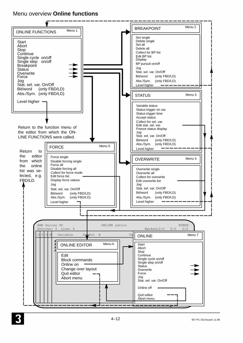
Return to the function menu ofthe editor from which the ON-LINE FUNCTIONS were called.
Return tothe editorfrom whichthe onlinelist was se-lected, e.g.FBD/LD.
Menu overview Online functions
Force
FORCE
Edit force list
Abs./Sym.Level higher
Bit/word
JogStat. sel. var. On/Off
Display force values
Disable forcing single
Edit BP list
Overwrite single
Display
Delete single
Delete all
BP pursuit on/off
Accept status
Force single
Force allDisable forcing all
Entries: 4 Line: 0 Marked:D:0 F:0 0:0
ONLINE EDITOR Menu 6
ONLINE Menu 7
EditBlock commandsOnline onChange over layoutQuit editorAbort menu
StartAbortStopContinueSingle cycle on/offSingle step on/offStatusOverwriteForceJogStat. sel. var. On/Off
Online off
Quit editorAbort menu
Menu 1Menu 2
Menu 3
Menu 4
Menu 5
Collect for BP list
Collect for force mode
Collect for sel. var.
Collect for overwrite
Freeze status display
(only FBD/LD)(only FBD/LD)
on/offon/off
(only FBD/LD)(only FBD/LD)
(only FBD/LD)(only FBD/LD)
(only FBD/LD)(only FBD/LD)
Bit/word (only FBD/LD)
Abs./Sym. (only FBD/LD)
D F O M
4–13907 PC 331/Issued: 11.98
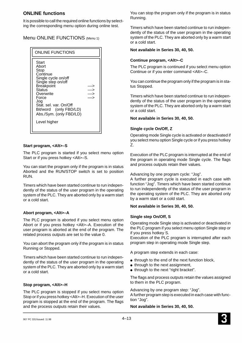
ONLINE functions
It is possible to call the required online functions by select-ing the corresponding menu option during online test.
Menu ONLINE FUNCTIONS (Menu 1)
ONLINE FUNCTIONS
StartAbortStopContinue
Abs./Sym. (only FBD/LD)
Level higher
Bit/word (only FBD/LD)
Single cycle on/offSingle step on/offBreakpointStatusOverwrite
JogStat. sel. var. On/Off
Force
––>––>––>––>
Start program, <Alt>–S
The PLC program is started if you select menu optionStart or if you press hotkey <Alt>–S.
You can start the program only if the program is in statusAborted and the RUN/STOP switch is set to positionRUN.
Timers which have been started continue to run indepen-dently of the status of the user program in the operatingsystem of the PLC. They are aborted only by a warm startor a cold start.
Abort program, <Alt>–A
The PLC program is aborted if you select menu optionAbort or if you press hotkey <Alt>–A. Execution of theuser program is aborted at the end of the program. Therelated process outputs are set to the value 0.
You can abort the program only if the program is in statusRunning or Stopped.
Timers which have been started continue to run indepen-dently of the status of the user program in the operatingsystem of the PLC. They are aborted only by a warm startor a cold start.
Stop program, <Alt>–H
The PLC program is stopped if you select menu optionStop or if you press hotkey <Alt>–H. Execution of the userprogram is stopped at the end of the program. The flagsand the process outputs retain their values.
You can stop the program only if the program is in statusRunning.
Timers which have been started continue to run indepen-dently of the status of the user program in the operatingsystem of the PLC. They are aborted only by a warm startor a cold start.
Not available in Series 30, 40, 50.
Continue program, <Alt>–C
The PLC program is continued if you select menu optionContinue or if you enter command <Alt>–C.
You can continue the program only if the program is in sta-tus Stopped.
Timers which have been started continue to run indepen-dently of the status of the user program in the operatingsystem of the PLC. They are aborted only by a warm startor a cold start.
Not available in Series 30, 40, 50.
Single cycle On/Off, Z
Operating mode Single cycle is activated or deactivated ifyou select menu option Single cycle or if you press hotkeyZ.
Execution of the PLC program is interrupted at the end ofthe program in operating mode Single cycle. The flagsand process outputs retain their values.
Advancing by one program cycle: “Jog”.A further program cycle is executed in each case withfunction “Jog”. Timers which have been started continueto run independently of the status of the user program inthe operating system of the PLC. They are aborted onlyby a warm start or a cold start.
Not available in Series 30, 40, 50.
Single step On/Off, S
Operating mode Single step is activated or deactivated inthe PLC program if you select menu option Single step orif you press hotkey S. Execution of the PLC program is interrupted after eachprogram step in operating mode Single step.
A program step extends in each case:
● through to the end of the next function block, ● through to the next assignment, ● through to the next “right bracket”.
The flags and process outputs retain the values assignedto them in the PLC program.
Advancing by one program step: “Jog”. A further program step is executed in each case with func-tion “Jog”.
Not available in Series 30, 40, 50.

4–14 907 PC 331/Issued: 11.98
Timers which have been started continue to run indepen-dently of the status of the user program in the operatingsystem of the PLC. They are aborted only by a warm startor a cold start.
Not available in 07 KR 31.
BreakpointExecution of the user program can be interrupted specifi-cally at the program points at which breakpoints havebeen set in operating mode Breakpoint. The followingsub–menu is called if you select menu option Breakpoint:
Not available in Series 30, 40, 50.
Menu BREAKPOINT (Menu 2)
BREAKPOINT
Set single
DisplayBP pursuit on/off
Abs./Sym. (only FBD/LD)
Level higher
Bit/word (only FBD/LD)
JogStat. sel. var. On/Off
Delete singleSet allDelete all
Edit BP listCollect for BP list
Set breakpoint, single, B
The cursor must first be on the appropriate line in the ex-tended IL or must be positioned on the correspondingvariable field in the FUPKOP where the breakpoint shouldbe set.
Selecting the Set single menu point or the hot key B al-lows the breakpoint to be set.
An input window from the breakpoint list appears:
B M Mod Addr Comment
* 001 0005
When you press <Return>, this confirms the display, thebreakpoint is activated immediately in the PLC and isadopted as marked in the breakpoint list.
The entry is rejected if you press <ESC>. No breakpoint isactivated.
Breakpoints can be set to the word numbers of the follow-ing elements:
● to the word No. of the last operand of a functionblock
● to the word No. of the operand after an assignmentsymbol
● to the word No. of a “right bracket” ● to the word No. of the end–of–program identifier.
Breakpoints can also be entered with the PLC programrunning.In the case of modularized projects, the word number dis-played in the window always relates to the start of therelevant module.
A maximum of 15 breakpoints are permitted simulta-neously.
Delete breakpoint single, <Alt>–B
The set breakpoint can be deleted singly, i.e. deactivatedin the PLC if you select menu option Delete single or if youpress hotkey <Alt>–B. You must move the cursor to thecorresponding variable or to the corresponding line be-fore selecting Delete single or before pressing <Alt>–B.You will then see the input window displayed beforehand.Confirm the display with <Return>, after which the break-point is deactivated immediately in the PLC . The markingof the breakpoint in the breakpoint list is cancelled. The entry is rejected if you press <ESC>. The breakpointremains set.
Set breakpoints all, W
The breakpoints entered in the breakpoint list with Edit BPlist are activated in the PLC if you select menu option Setall or if you press hotkey W.
Breakpoints can be set to the word numbers of the follow-ing elements:
● to the word No. of the last operand of a functionblock
● to the word No. of the operand after an assignmentsymbol
● to the word No. of a “right bracket” ● to the word No. of the end–of–program identifier.
Breakpoints can also be entered with the PLC programrunning.
Advancing to the next breakpoint: “Jog”.Program execution is enabled until the next breakpoint isreached with function “Jog”.
A maximum of 15 breakpoints are permitted simulta-neously.

4–15907 PC 331/Issued: 11.98
Delete breakpoints all, <Alt>–W
All set breakpoints can be cancelled at once, i.e. deacti-vated in the PLC, if you select menu option Delete all or ifyou press hotkey <Alt>–W. All markings are removedfrom the breakpoint list.
Collect for breakpoint list, 2
Program addresses can be entered in the breakpoint list ifyou select menu option Collect for BP list or if you press
hotkey 2. You must move the cursor to the correspondingvariable in the FBD or to the corresponding line of the ex-tended IL before execution of the function. The samerules apply as when setting individual breakpoints. Col-lection for the breakpoint list is not possible in the ladderdiagram.
Edit breakpoint list, L
You call the breakpoint list by selecting menu option EditBP list.
ABB Series 90 Breakpoint list KUNDE
B M Mod Addr Comment
* 001 0001
Entries: 1 Line: 1 Marked:B:1
You can then enter a list of breakpoint addresses, specify-ing the relevant module number, and these must then bemarked in column B with <F5>. The marking can be can-celled again with <F6>.
In the case of modularized projects, the word number al-ways refers to the start of the relevant module.
Display breakpoint, Q
Selecting the menu point Display or the hot key Q readsthe set breakpoints into the breakpoint list. They can bedisplayed with the function Enter BP list (enter breakpointlist, hot key L). The read–in breakpoints are marked.
In the case of modularized projects, the word number al-ways refers to the start of the relevant module.
Breakpoint persuit On/Off, P
The relevant, active breakpoint can be detected in thePLC and displayed in the FBD/LD (orientation column orvariable field), in the extended IL (corresponding line) orin the translated IL (corresponding line) if you select menuoption BP pursuit on/off or if you press hotkey P.
If the active breakpoint is not in the current module in thecase of modularized projects, the current module is quitand the corresponding module is automatically called up.Any entered changes are taken into account by an enqui-ry.
Jog, G
This command is operable only in modes “Single step” or“Single cycle” or if breakpoints have been set.
Selecting menu option Jog or pressing hotkey G meansthat
● the program executes the next program step inSingle step mode,
● the program is run through once in Single cyclemode,
● the program is executed through to the next break-point if breakpoints are set.
Status of selected variables On/Off, A
Only the status values of the variables selected by theuser are updated on the monitor if you select menu optionStat. sel. var. On/Off or if you press hotkey A.
The variables are selected by entering them in the onlinelist and marking them in column D. The statuses of all oth-er variables are no longer updated.
4–16 907 PC 331/Issued: 11.98
This operating mode is deactivated again if you selectmenu option Stat. sel. var. On/Off or if you press hotkey Aagain, and the statuses of all variables are updated on themonitor.
Bit/word (in the FBD/LD only), X
The status display for word variables is switched over be-tween the two display modes Binary and Word value ifyou select menu option Bit/word (only FBD/LD) or if youpress hotkey X.
Binary display mode:● The variable name is highlighted in the FBD/LD if the
value is not equal to 0
Word value display mode: ● The value of the word variable is displayed in place of
the variable name in the FBD/LD
Absolute/symbolic (in the FBD/LD only), <F9>
The status display is switched over between the two dis-play modes Absolute and Symbolic if you select menu op-tion Abs./sym. (only FBD/LD) or if you press key <F9>.This means that either the absolute or the symbolic desig-nations are shown for the variables.
Level higher
You return to menu ONLINE FUNCTIONS if you selectmenu option Level higher.
StatusThe programming system makes available various op-tions for status display of variables. The variables are al-ways displayed cycle–consistently, i.e. the variable val-ues supplied by the PLC originate from the same programcycle.The following sub–menu is called if you select menu op-tion Status:
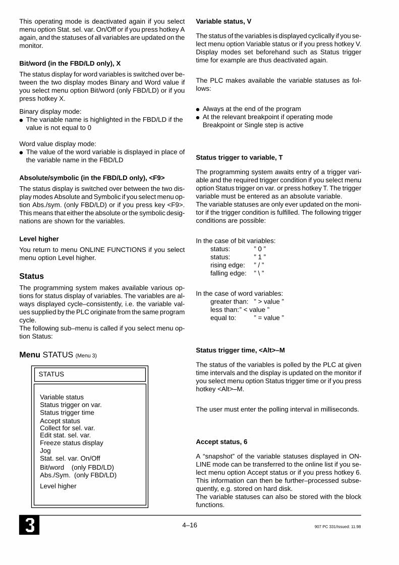
Menu STATUS (Menu 3)
STATUS
Variable statusStatus trigger on var.Status trigger time
Abs./Sym. (only FBD/LD)
Level higher
Bit/word (only FBD/LD)
JogStat. sel. var. On/Off
Edit stat. sel. var.
Accept statusCollect for sel. var.
Freeze status display
Variable status, V
The status of the variables is displayed cyclically if you se-lect menu option Variable status or if you press hotkey V.Display modes set beforehand such as Status triggertime for example are thus deactivated again.
The PLC makes available the variable statuses as fol-lows:
● Always at the end of the program● At the relevant breakpoint if operating mode
Breakpoint or Single step is active
Status trigger to variable, T
The programming system awaits entry of a trigger vari-able and the required trigger condition if you select menuoption Status trigger on var. or press hotkey T. The triggervariable must be entered as an absolute variable. The variable statuses are only ever updated on the moni-tor if the trigger condition is fulfilled. The following triggerconditions are possible:
In the case of bit variables:status: ” 0 ” status: ” 1 ”rising edge: ” / ” falling edge: ” \ ”
In the case of word variables:greater than: ” > value ” less than:” < value ” equal to: ” = value ”
Status trigger time, <Alt>–M
The status of the variables is polled by the PLC at giventime intervals and the display is updated on the monitor ifyou select menu option Status trigger time or if you presshotkey <Alt>–M.
The user must enter the polling interval in milliseconds.
Accept status, 6
A “snapshot” of the variable statuses displayed in ON-LINE mode can be transferred to the online list if you se-lect menu option Accept status or if you press hotkey 6.This information can then be further–processed subse-quently, e.g. stored on hard disk. The variable statuses can also be stored with the blockfunctions.

4–17907 PC 331/Issued: 11.98
Collect for selected variables, 5Variables can be collected for function “Display selectedvariables” (Stat. sel. var. On/Off) if you select menu op-tion Collect for sel. var. or if you press hotkey 5. You mustmove the cursor to the corresponding variable in the FBDor to the corresponding line in the extended IL before ex-ecution of the function. The corresponding variables areentered in the online list and marked in column D. Only theselected variables are then updated with hotkey A (Stat.sel. var. On/Off).
Edit status of selected variables, O (Edit online list)
The editor for processing the online list is called if you se-lect menu option Edit stat. sel. var. or if you press hotkeyO.
The programming system displays the following:
ABB Series 90 ONLINE editor KUNDE
D F O M Variable Symbol B Value Long text
* A 62,00 B 0A 62,01 B 0
Entries: 2 Line: 0 Marked: D:1 F:0 O:0
Any selection of variables can be edited in the online list.
The online list is required in order to:
● display status values of variables in the online list;
● display status values of selected variables in the pro-gram (FBD/LD, extended IL; column D).You must first move the cursor to column D. Mark therequired variable with <F5>. Only the status valuesof the marked variables are then displayed in the pro-gram. You can cancel the marking again with <F6>;
● overwrite status values of variables in the PLC (col-umn O);
● force status values of inputs and outputs in the PLC(column F);
● store status values of variables in the online list (col-umn M)Set the marking with <F5>. Delete the marking with<F6>; please refer to Block processing for further op-erations.
Menu ONLINE–EDITOR can be called within the editorfor processing the online list.
Menu ONLINE–EDITOR (Menu 6)
ONLINE EDITOR
EditBlock commands
Abort menuQuit editor
Change over layout
Online On

4–18 907 PC 331/Issued: 11.98
Online On
The programming system displays the following if you se-lect menu option Online On and then press the space bar:
ABB Series 90 ONLINE editor KUNDE
Variable Symbol B Var
A 62,00 B 1A 62,01 B 0
Entries: 2 Line: 0 Marked: D:1 F:0 O:0
ONLINE
StartAbortStopContinueSingle cycle on/offSingle step on/offOverwrite ––>Force ––>JogStat. sel. var. On/OffOnline offQuit editorAbort menu
The programming system now communicates with thePLC. The status values of the variables are displayed andthe online functions are available.
____________________________________________________________________________________________
Menu STATUS, continued (Menu 3)
Freeze status display, 0 (Zero)
The current variable statuses are frozen on the monitorwhen this menu is called, and the user can decide wheth-er he wishes to also transfer this status to the online listwith menu Accept status.
Jog, G
This command is operative only in modes “Single step”,“Single cycle” or if breakpoints have been set.Selecting menu option Jog or pressing hotkey G meansthat
● the program executes the next program step in Sing-le–step mode,
● the program is run through once in Single–cyclemode,
● the program is executed as far as the next breakpointif breakpoints have been set.
Status of selected variables On/Off, A
Only the status values of the variables selected by theuser are updated on the monitor if you select menu optionStat. sel. var. On/Off or if you press hotkey A. The vari-ables are selected by entering them in the online list andmarking them in column D. The statuses of all other vari-ables are no longer updated.
This operating mode is deactivated again and the sta-tuses of all variables are updated on the monitor by se-lecting menu option Stat. sel. var. On/Off again or bypressing hotkey A again.
Bit/word (in the FBD/LD only), X
The status display for word variables is switched over be-tween the display modes Binary and Word value if you se-lect menu option Bit/word (only FBD/LD) or if you presshotkey X.
Binary display mode:The variable name is highlighted in the FBD/LD if the val-ue is not equal to 0
Word value display mode: The value of the word variable is displayed in place of thevariable name in the FBD/LD
Absolute/symbolic (in the FBD/LD only), <F9>
The status display is switched over between the two dis-play modes Absolute and Symbolic, i.e. either the abso-lute or the symbolic designations are displayed for thevariables, if you select menu option Abs./sym. (only FBD/LD) or if you press key <F9>.
Level higher
You return to menu ONLINE FUNCTIONS if you selectmenu option Level higher.
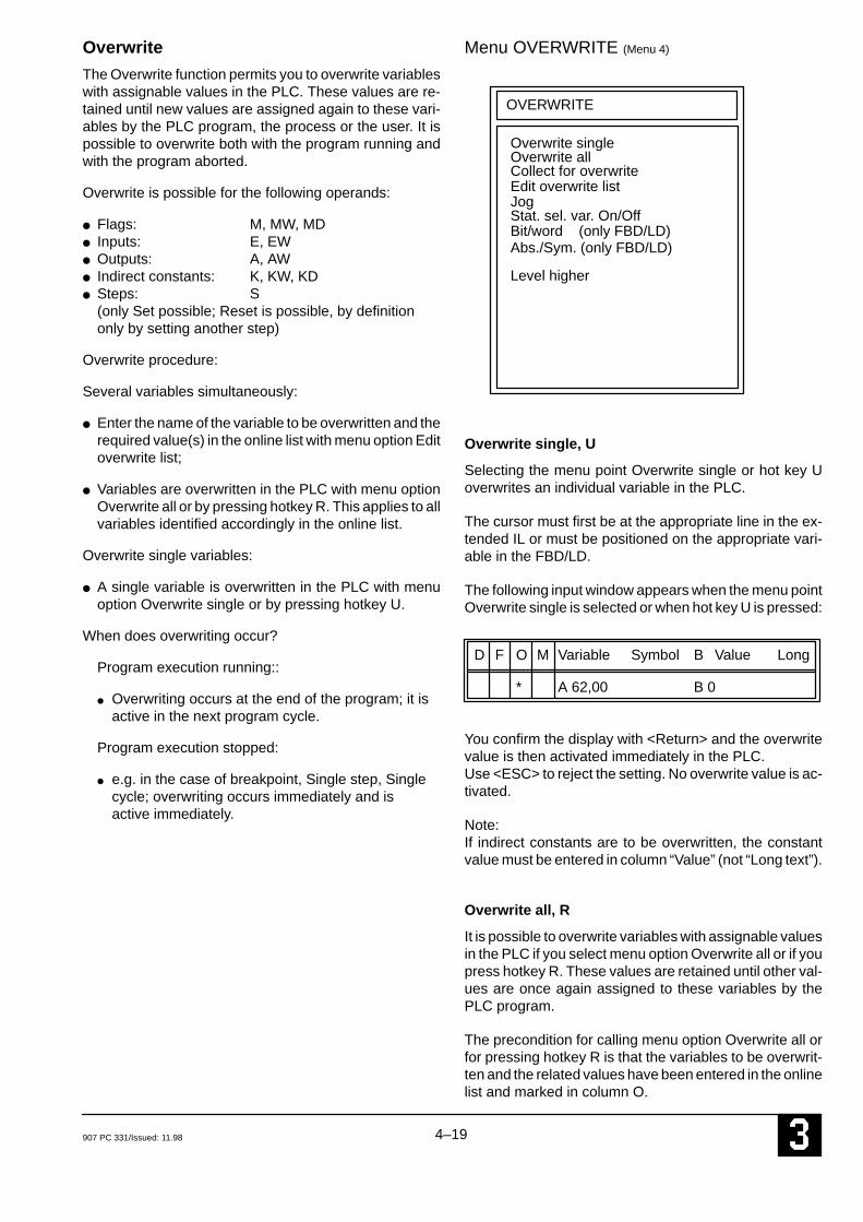
4–19907 PC 331/Issued: 11.98
Overwrite
The Overwrite function permits you to overwrite variableswith assignable values in the PLC. These values are re-tained until new values are assigned again to these vari-ables by the PLC program, the process or the user. It ispossible to overwrite both with the program running andwith the program aborted.
Overwrite is possible for the following operands:
● Flags: M, MW, MD● Inputs: E, EW● Outputs: A, AW● Indirect constants: K, KW, KD● Steps: S
(only Set possible; Reset is possible, by definitiononly by setting another step)
Overwrite procedure:
Several variables simultaneously:
● Enter the name of the variable to be overwritten and therequired value(s) in the online list with menu option Editoverwrite list;
● Variables are overwritten in the PLC with menu optionOverwrite all or by pressing hotkey R. This applies to allvariables identified accordingly in the online list.
Overwrite single variables:
● A single variable is overwritten in the PLC with menuoption Overwrite single or by pressing hotkey U.
When does overwriting occur?
Program execution running::
● Overwriting occurs at the end of the program; it isactive in the next program cycle.
Program execution stopped:
● e.g. in the case of breakpoint, Single step, Singlecycle; overwriting occurs immediately and isactive immediately.
Menu OVERWRITE (Menu 4)
OVERWRITE
Overwrite allCollect for overwrite
Abs./Sym. (only FBD/LD)
Level higher
Bit/word (only FBD/LD)
JogStat. sel. var. On/Off
Overwrite single
Edit overwrite list
Overwrite single, U
Selecting the menu point Overwrite single or hot key Uoverwrites an individual variable in the PLC.
The cursor must first be at the appropriate line in the ex-tended IL or must be positioned on the appropriate vari-able in the FBD/LD.
The following input window appears when the menu pointOverwrite single is selected or when hot key U is pressed:
D F O M Variable Symbol B Value Long
* A 62,00 B 0
You confirm the display with <Return> and the overwritevalue is then activated immediately in the PLC.Use <ESC> to reject the setting. No overwrite value is ac-tivated.
Note:If indirect constants are to be overwritten, the constantvalue must be entered in column “Value” (not “Long text”).
Overwrite all, R
It is possible to overwrite variables with assignable valuesin the PLC if you select menu option Overwrite all or if youpress hotkey R. These values are retained until other val-ues are once again assigned to these variables by thePLC program.
The precondition for calling menu option Overwrite all orfor pressing hotkey R is that the variables to be overwrit-ten and the related values have been entered in the onlinelist and marked in column O.
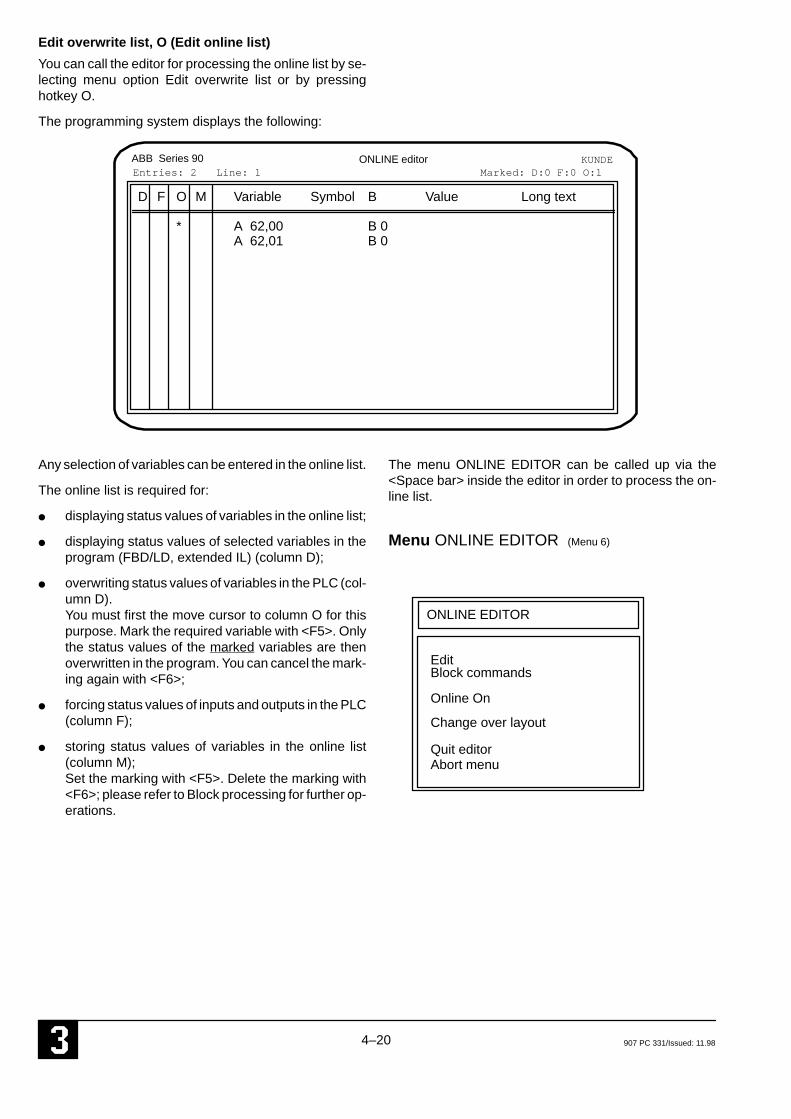
4–20 907 PC 331/Issued: 11.98
Edit overwrite list, O (Edit online list)
You can call the editor for processing the online list by se-lecting menu option Edit overwrite list or by pressinghotkey O.
The programming system displays the following:
ABB Series 90 ONLINE editor KUNDE
D F O M Variable Symbol B Value Long text
* A 62,00 B 0A 62,01 B 0
Entries: 2 Line: 1 Marked: D:0 F:0 O:1
Any selection of variables can be entered in the online list.
The online list is required for:
● displaying status values of variables in the online list;
● displaying status values of selected variables in theprogram (FBD/LD, extended IL) (column D);
● overwriting status values of variables in the PLC (col-umn D).You must first the move cursor to column O for thispurpose. Mark the required variable with <F5>. Onlythe status values of the marked variables are thenoverwritten in the program. You can cancel the mark-ing again with <F6>;
● forcing status values of inputs and outputs in the PLC(column F);
● storing status values of variables in the online list(column M); Set the marking with <F5>. Delete the marking with<F6>; please refer to Block processing for further op-erations.
The menu ONLINE EDITOR can be called up via the<Space bar> inside the editor in order to process the on-line list.
Menu ONLINE EDITOR (Menu 6)
ONLINE EDITOR
EditBlock commands
Abort menuQuit editor
Change over layout
Online On

4–21907 PC 331/Issued: 11.98
Online On
When the menu point Online On is selected, the program-ming system starts communicating with the PLC. The sta-tus values of the variables are displayed and the onlinefunctions are available. If the <Space bar> is alsopressed, the following image appears.
ABB Series 90 ONLINE editor KUNDE
Variable Symbol B Var
A 62,00 B 1A 62,01 B 0
Entries: 2 Line: 0 Marked: D:1 F:0 O:0
ONLINE
StartAbortStopContinueSingle cycle on/offSingle step on/offStatus ––>Overwrite ––>Force ––>JogStat. sel. var. On/OffOnline offQuit editorAbort menu
PLC:$ PRG:1 = running
____________________________________________________________________________________________
Menu OVERWRITE, continued (Menu 4)
Collect for overwrite, 4
Selecting the menu point Collect for overwrite or pressinghot key 4 enables variables to be collected for overwriting.
The cursor must be positioned on the appropriate variablefield in the FBD or must be positioned on the appropriateline in the extended IL before the function is carried out.
The appropriate variables are entered in the online listand are marked in column O. The variables entered in theonline list and marked in column O are overwritten withthe hot key R (Overwrite all).
Jog, G
This command is operative only in modes “Single step”,“Single cycle” or if breakpoints have been set.
Selecting menu option Jog or pressing hotkey G meansthat
● the program executes the next program step in Sing-le–step mode,
● the program is run through once in Single–cyclemode,
● the program is executed through to the next break-point if breakpoints have been set.
Status of selected variables On/Off, A
Only the status values of the variables selected by theuser are updated on the monitor if you select menu optionStat. sel. var. On/Off or if you press hotkey A. The vari-ables are selected by entering them in the online list andmarking them in column D. The statuses of all other vari-ables are no longer updated.
This operating mode is deactivated again and the sta-tuses of all variables are updated on the monitor by se-lecting menu option Stat. sel. var. On/Off again or if youpress hotkey A again.
Bit/word (in the FBD/LD only), X
The status display for word variables is switched over be-tween the display modes Binary and Word value if you se-lect menu option Bit/word (only FBD/LD) or if you presshotkey X.
Binary display mode:
● The variable name is highlighted in the FBD/LD if thevalue is not equal to 0
Word value display mode:
● The value of the word variable is displayed in place ofthe variable name in the FBD/LD.
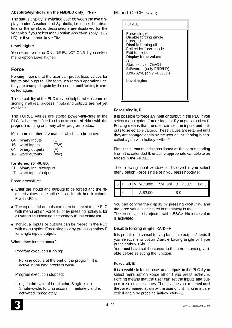
4–22 907 PC 331/Issued: 11.98
Absolute/symbolic (in the FBD/LD only), <F9>
The status display is switched over between the two dis-play modes Absolute and Symbolic, i.e. either the abso-lute or the symbolic designations are displayed for thevariables if you select menu option Abs./sym. (only FBD/LD) or if you press key <F9>.
Level higher
You return to menu ONLINE FUNCTIONS if you selectmenu option Level higher.
ForceForcing means that the user can preset fixed values forinputs and outputs. These values remain operative untilthey are changed again by the user or until forcing is can-celled again.
This capability of the PLC may be helpful when commis-sioning if all real process inputs and outputs are not yetavailable.
The FORCE values are stored power–fail–safe in thePLC if a battery is fitted and can be entered either with theprogram running or in any other program status.
Maximum number of variables which can be forced:
64 binary inputs (E)16 word inputs (EW)64 binary outputs (A)16 word outputs (AW)
for Series 30, 40, 50:31 binary inputs/outputs7 word inputs/outputs
Force procedure:
● Enter the inputs and outputs to be forced and the re-quired values in the online list and mark them in columnF with <F5>.
● The inputs and outputs can then be forced in the PLCwith menu option Force all or by pressing hotkey E forall variables identified accordingly in the online list.
● Individual inputs or outputs can be forced in the PLCwith menu option Force single or by pressing hotkey Ffor single inputs/outputs.
When does forcing occur?
Program execution running:
– Forcing occurs at the end of the program. It isactive in the next program cycle.
Program execution stopped:
– e.g. in the case of breakpoint, Single–step, Single–cycle; forcing occurs immediately and isactivated immediately.
Menu FORCE (Menu 5)
FORCE
Force singleDisable forcing single
Abs./Sym. (only FBD/LD)
Level higher
Bit/word (only FBD/LD)
JogStat. sel. var. On/Off
Force allDisable forcing all
Edit force listDisplay force values
Collect for force mode
Force single, F
It is possible to force an input or output in the PLC if youselect menu option Force single or if you press hotkey F.Forcing means that the user can set the inputs and out-puts to selectable values. These values are retained untilthey are changed again by the user or until forcing is can-celled again with hotkey <Alt>–F.
First, the cursor must be positioned on the correspondingline in the extended IL or at the appropriate variable to beforced in the FBD/LD.
The following input window is displayed if you selectmenu option Force single or if you press hotkey F:
D F O M Variable Symbol B Value Long
* A 62,00 B 0
You can confirm the display by pressing <Return>, andthe force value is activated immediately in the PLC.The preset value is rejected with <ESC>. No force valueis activated.
Disable forcing single, <Alt>–F
It is possible to cancel forcing for single outputs/inputs ifyou select menu option Disable forcing single or if youpress hotkey <Alt>–F.You must have set the cursor to the corresponding vari-able before selecting the function.
Force all, E
It is possible to force inputs and outputs in the PLC if youselect menu option Force all or if you press hotkey E.Forcing means that the user can set the inputs and out-puts to selectable values. These values are retained untilthey are changed again by the user or until forcing is can-celled again by pressing hotkey <Alt>–E.
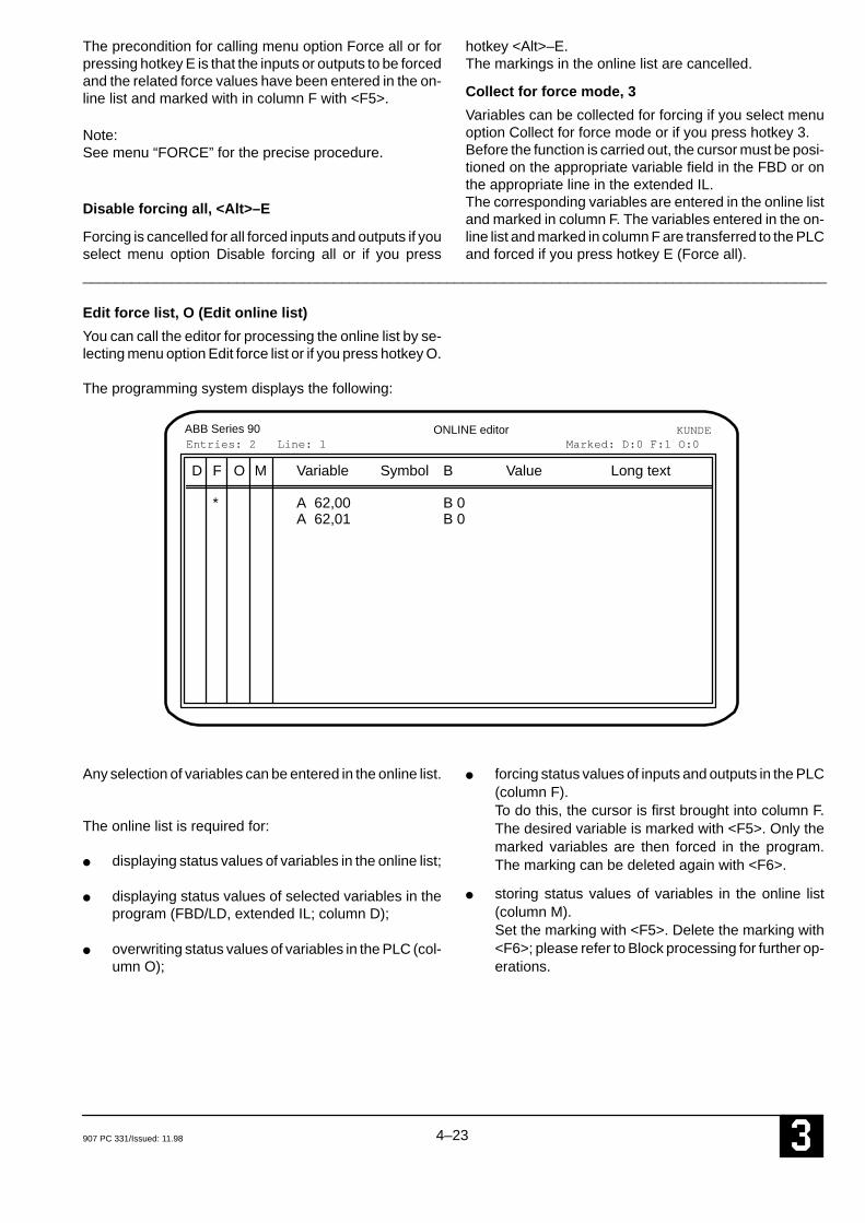
4–23907 PC 331/Issued: 11.98
The precondition for calling menu option Force all or forpressing hotkey E is that the inputs or outputs to be forcedand the related force values have been entered in the on-line list and marked with in column F with <F5>.
Note: See menu “FORCE” for the precise procedure.
Disable forcing all, <Alt>–E
Forcing is cancelled for all forced inputs and outputs if youselect menu option Disable forcing all or if you press
hotkey <Alt>–E. The markings in the online list are cancelled.
Collect for force mode, 3
Variables can be collected for forcing if you select menuoption Collect for force mode or if you press hotkey 3.Before the function is carried out, the cursor must be posi-tioned on the appropriate variable field in the FBD or onthe appropriate line in the extended IL.The corresponding variables are entered in the online listand marked in column F. The variables entered in the on-line list and marked in column F are transferred to the PLCand forced if you press hotkey E (Force all).
____________________________________________________________________________________________
Edit force list, O (Edit online list)
You can call the editor for processing the online list by se-lecting menu option Edit force list or if you press hotkey O.
The programming system displays the following:
ABB Series 90 ONLINE editor KUNDE
D F O M Variable Symbol B Value Long text
* A 62,00 B 0A 62,01 B 0
Entries: 2 Line: 1 Marked: D:0 F:1 O:0
Any selection of variables can be entered in the online list.
The online list is required for:
● displaying status values of variables in the online list;
● displaying status values of selected variables in theprogram (FBD/LD, extended IL; column D);
● overwriting status values of variables in the PLC (col-umn O);
● forcing status values of inputs and outputs in the PLC(column F).To do this, the cursor is first brought into column F.The desired variable is marked with <F5>. Only themarked variables are then forced in the program.The marking can be deleted again with <F6>.
● storing status values of variables in the online list(column M).Set the marking with <F5>. Delete the marking with<F6>; please refer to Block processing for further op-erations.

4–24 907 PC 331/Issued: 11.98
You can call menu ONLINE EDITOR within the editor forprocessing the online list.
Menu ONLINE EDITOR (Menu 6)
ONLINE EDITOR
EditBlock commands
Abort menuQuit editor
Change over layout
Online on
____________________________________________________________________________________________
Online On
When the menu point Online On is selected, the program-ming system starts to communicate with the PLC. Thestatus values of the variables are displayed and the onlinefunctions are available. The following image appears ifthe <Space bar> is also pressed.
ABB Series 90 ONLINE editor KUNDE
Variable Symbol B Var
A 62,00 B 1A 62,01 B 0
Entries: 2 Line: 0 Marked: D:1 F:0 O:0
ONLINE
StartAbortStopContinueSingle cycle on/offSingle step on/offStatus ––>Overwrite ––>Force ––>JogStat. sel. var. On/OffOnline offQuit editorAbort menu
PLC:$ PRG:1 = running

4–25907 PC 331/Issued: 11.98
Menu FORCE, continued (Menu 5)
Display force values, <Alt>–D
The inputs and outputs forced in the PLC and the relatedforce values are read out from the PLC and stored in theonline list if you select menu option Display force values.The information on the forced inputs and outputs is avail-able if you select menu option Edit force list or if you presshotkey O (in online mode). The forced inputs and outputsread in are marked as described above.
Jog, G
This command is operative only in modes “Single–step”,“Single–cycle” or if breakpoints have been set.Selecting menu option Jog or pressing hotkey G meansthat
● the program executes the next program step in Sing-le–step mode,
● the program is run through once in Single–cyclemode,
● the program is executed through to the next break-point if breakpoints have been set.
Status of selected variables On/Off, A
Only the status values of the variables selected by theuser are updated on the monitor if you select menu optionStat. sel. var. On/Off or if you press hotkey A. The vari-ables are selected by entering them in the online list andmarking them in column D. The statuses of all other vari-ables are no longer updated. This operating mode can bedeactivated again and the statuses of all variables are up-dated on the monitor if you select menu option Stat. sel.var. On/Off again or if you press hotkey A again.
Bit/word (in the FBD/LD only), X
The status display for word variables is switched over be-tween the two display modes Binary and Word value ifyou select menu option Bit/word (only FBD/LD) or if youpress hotkey X.
Binary display mode:● The variable name is highlighted in the FBD/LD if the
value is not equal to 0.
Word value display mode:● The value of the word variable is displayed in place of
the variable name in the FBD/LD.
Absolute/symbolic (in the FBD/LD only), <F9>
The status display is switched over between the two dis-play modes Absolute and Symbolic, i.e. either the abso-lute or the symbolic designations are displayed for thevariables, if you select menu option Abs./sym. (only FBD/LD) or if you press key <F9>.
Level higher
You return to menu ONLINE FUNCTIONS if you selectmenu option Level higher.
Menu ONLINE FUNCTIONS continued (Menu
1)
Jog, G
This command is operative only in modes “Single–step”,“Single–cycle” or if breakpoints have been set.Selecting menu option Jog or pressing hotkey G meansthat
● the program executes the next program step in Sing-le–step mode,
● the program is run through once in Single–cyclemode,
● the program is executed through to the next break-point if breakpoints have been set.
Status of selected variables On/Off, A
Only the status values of the variables selected by theuser are updated on the monitor if you select menu optionStat. sel. var. On/Off or if you press hotkey A. The vari-ables are selected by entering them in the online list andmarking them in column D. The statuses of all other vari-ables are no longer updated. This operating mode can be deactivated again and thestatuses of all variables are updated on the monitor if youselect menu option Stat. sel. var. On/Off again or if youpress hotkey A again.
Bit/word (in the FBD/LD only), X
The status display for word variables is switched over be-tween the two display modes Binary and Word value ifyou select menu option Bit/word (only FBD/LD) or if youpress hotkey X.
Binary display mode:● The variable name is highlighted in the FBD/LD if the
value is not equal to 0.
Word value display mode: ● The value of the word variable is displayed in place of
the variable name in the FBD/LD.

4–26 907 PC 331/Issued: 11.98
Absolute/symbolic (in the FBD/LD only), <F9>
The status display is switched over between the two dis-play modes Absolute and Symbolic, i.e. either the abso-lute or the symbolic designations are displayed for thevariables, if you select menu option Abs./sym. (only FBD/LD) or if you press key <F9>.
Level higher
You return to the function menu of the editor from whichthe ONLINE FUNCTIONS have been called if you selectmenu option Level higher.

5–1907 PC 331/Issued: 11.98
5 ”Compare” program
____________________________________________________________________________________________
Method of operation of COMPARE
COMPARE is a help program for comparing two IL files. Itcompares two print files record by record as from a partic-ular address through to the end of the shortest file. Itreads only the instructions of the instruction lists printedinto the files. The header, footer, comments and symbolsare ignored. As a comparison result, all records which donot correspond with each other are displayed.
If the two compared records are of a different length, bothare displayed. The comparison is then continued in thenext record. If the only difference between the two files isthat records have been deleted or added, COMPARE dis-plays the rest of the records as being different as from thepoint at which the records differ. In this case, COMPAREoffers the possibility of starting the comparison of the filesas from certain record numbers, in every file from a differ-ent record number. Different comparison types are possi-ble by defining parameters.
Before using COMPARE
If you wish to compare two PLC programs with each oth-er, you must print out the IL list of every program. This ispossible via the main menu point Print 1 –> submenu IL.For Print target, simply state a file name instead of PRN.
Note:Comments must not be within records of the IL beingprinted.The left edge of the print file must be at 10 (main menu point Print Param. –> Sub–menu Print pa-rameter –> Left edge: 10).
Using COMPARE
To use COMPARE, you must use the following syntax:
COMPARE file1 file2 output / parameter
File1 and File2 are the names of the two files to be com-pared.
You can display or file the comparison result in differentways with Output:
● If you omit Output, the comparison result is displayed on the screen.
● If you state PRN, the comparison result is printedout on the printer.
● If you give a File name, the comparison result isstored in this file.
By stating different Parameters, you can control the typeof the comparison and the output. Several parametersare simply given together, e.g. ”/DN”.
The following parameters are available:
/L Ignore record length This parameter allows the comparison of re-cords of different lengths from the start of therecord through to the end of the shorter recordor until the first difference.
/S Ignore record number This parameter allows the comparison of re-cords if they have different record numbers.
/W Ignore word numberWith this parameter, the word numbers are ig-nored during the comparison.
/C Ignore commandsWith this parameter, the commands within thewords are ignored during the comparison. Inthis way, for example, the difference between”&” and ”&N” is ignored.
/T Ignore operand type With this parameter, the operand types are ig-nored during the comparison.
/A Ignore operand addressWith this parameter, the operand addressesare ignored during the comparison.
/D State only the number of different recordsWith this parameter, only the number of differ-ent records is given.
/N Screen display without interruptionNormally, the display of the comparison resultis stopped after every full screen page and isnot continued again until after a key is pressed.This parameter switches off this interruption.
/Qn Abort after n differencesThis parameter aborts the display after n differ-ences.

5–2 907 PC 331/Issued: 11.98
/1#xxxxx Start comparison in file 1 as from record num-ber xxxxxWith this parameter, the comparison in file 1 isnot started until as from record number xxxxx.The record number must always be given as 5digits (e.g. /1#01013). If this record number does not exist, an errormessage is issued. If different start address-es are given for both files, the parameters /S(ignore record number) and /W (ignore wordnumber) are switched on automatically.
/2#xxxxx Start comparison in file 2 as from record num-ber xxxxxWith this parameter, the comparison in file 2 isnot started until as from record number xxxxx.The record number must always be given as 5digits (e.g. /2#01013).If this record number does not exist, an errormessage is issued. If different start address-es are given for both files, the parameters /S(ignore record number) and /W (ignore wordnumber) are switched on automatically.
After the comparison, the number of differences found isstated. If no differences were found, the files are identical(apart from differences in the case of ignored elements).The comparison can also be aborted by pressing <Esc> .
Examples
COMPARE IL1.PRT IL2.PRTThese two files are compared and the comparison resultis shown on the screen.
COMPARE IL1.PRT IL2.PRT COMPARE.DATThese two files are compared and the comparison resultis written into the file COMPARE.DAT.
COMPARE IL1.PRT IL2.PRT PRN /1#00002TThese two files are compared. The comparison does notstart until as from record number 2 in IL1.PRT. Also, theoperand types are ignored. The comparison result is out-put on the printer.

907 PC 331 / Issued: 08.99 5-3 3
Variable listIn the user program, 5 different variable types are used:
� The physical, digital or analog input and output vari-ables
� The internal bit, word or double word flags are used forintermediate calculations in the user program.
� The indirect bit, word or double word constants.
� The step chains, which allow the simple programmingof sequential operations.
� The historical values: Certain functions require severalprogram cycles for execution. For instance, the vari-able ZEIT is updated in each cycle during the process-ing of a time function, i.e. this variable is an examplefor a historical value.
It is not possible to directly access the historical val-ues via the user program for basic units of the series 40and 50.
Notes on the historical values:The maximum permissible number of historical values fora project is 256.
A list of the functions with their historical values can befound in the appendix.
The historical values of the timer functions are indepen-dent of the other functions historical value list. The numberof authorized timer functions is unlimited, but the numberof timer functions used at the same time is limited to 42.
Value ranges:
– Bit variables (status 0 or 1)
– Word variables (value range -32768 to 32767)
– Double word variables (value range -2147483648 to2147483647)
– Text (ASCII characters)

5-43 907 PC 331 / Issued: 08.99
Type Variables Description Seriesfrom to 30 40 50 90
Digital inputs E 00,00 E 61,15 Digital inputs of the CS31 system bus x xE 62,00 E 62,07 Digital inputs of the basic unit x xE 62,00 E 62,11 Digital inputs of the basic unit xE 63,00 E 68,15 Digital inputs of the basic unit x x
expansionsAnalog inputs EW 00,00 EW 61,15 Analog inputs of the CS31 system bus x
EW 00,00 EW 05,15 Analog inputs of the CS31 system bus xEW 06,15 Fast counter, inquiring counter content xEW 07,00 EW 07,07 Reserved variables xEW 07,08 EW 07,14 Reading real-time clock xEW 07,15 Status for CS31 system bus xEW 62,00 First potentiometer of the basic units x xEW 62,01 Second potentiometer of the basic units x xEW 62,02 EW 62,07 Reserved variables x xEW 62,08 Seconds (0...59) xEW 62,09 Minutes (0...59) xEW 62,10 Hours (0...23) xEW 62,11 Weekdays (1...7) xEW 62,12 Days of the month xEW 62,13 Months xEW 62,14 Years xEW 62,15 Status word: x x
Bit 0: displaying class 2 errorsBit 1: for detection of the CS31 system bus inslave basic unitsBit 8 to 15: are used in master basic unitsand define the number of remote moduleswhich are detected on the CS31 system bus.
EW 63,00 EW 68,15 Analog inputs of the basic unit expansions x
x: valid for the specified series 30 = 07 KR 31, 07 KT 31 50 = 07 KR 51, 07 KT 5140 = 07 CR 41, 07 CT 41 90 = 07 KR 91, 07 KT 92, 07 KT 93, 07 KT 94For further information refer to volume 4, pages 1-1 to 1-3
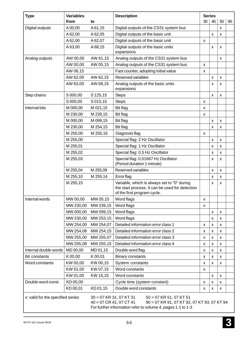
907 PC 331 / Issued: 08.99 5-5 3
Type Variables Description Seriesfrom to 30 40 50 90
Digital outputs A 00,00 A 61,15 Digital outputs of the CS31 system bus xA 62,00 A 62,05 Digital outputs of the basic unit x xA 62,00 A 62,07 Digital outputs of the basic unit xA 63,00 A 68,15 Digital outputs of the basic units x x
expansionsAnalog outputs AW 00,00 AW 61,15 Analog outputs of the CS31 system bus x
AW 00,00 AW 05,15 Analog outputs of the CS31 system bus xAW 06,15 Fast counter, adopting initial value xAW 62,00 AW 62,15 Reserved variables x xAW 63,00 AW 68,15 Analog outputs of the basic units x x
expansionsStep chains S 000,00 S 125,15 Steps x x
S 000,00 S 015,15 Steps xInternal bits M 000,00 M 021,15 Bit flag x
M 230,00 M 239,15 Bit flag xM 000,00 M 099,15 Bit flag x xM 230,00 M 254,15 Bit flag x xM 255,00 M 255,15 Diagnosis flag xM 255,00 Special flag: 2 Hz Oscillator x xM 255,01 Special flag: 1 Hz Oscillator x xM 255,02 Special flag: 0,5 Hz Oscillator x xM 255,03 Special flag: 0,01667 Hz Oscillator x x
(Period duration 1 minute)M 255,04 M 255,09 Reserved variables x xM 255,10 M 255,14 Error flag x xM 255,15 Variable, which is always set to "0" during x x
the start process. It can be used for detectionof the first program cycle.
Internal words MW 00,00 MW 05,15 Word flags xMW 230,00 MW 239,15 Word flags xMW 000,00 MW 099,15 Word flags x xMW 230,00 MW 253,15 Word flags x xMW 254,00 MW 254,07 Detailed information error class 1 x x xMW 254,08 MW 254,15 Detailed information error class 2 x x xMW 255,00 MW 255,07 Detailed information error class 3 x x xMW 255,08 MW 255,15 Detailed information error class 4 x x x
Internal double words MD 00,00 MD 01,15 Double word flag x x xBit constants K 00,00 K 00,01 Binary constants x x xWord constants KW 00,00 KW 00,15 System constants x x x
KW 01,00 KW 07,15 Word constants xKW 01,00 KW 15,15 Word constants x x
Double word const. KD 00,00 Cycle time (system constant) x x xKD 00,01 KD 01,15 Double word constants x x x
x: valid for the specified series 30 = 07 KR 31, 07 KT 31 50 = 07 KR 51, 07 KT 5140 = 07 CR 41, 07 CT 41 90 = 07 KR 91, 07 KT 92, 07 KT 93, 07 KT 94For further information refer to volume 4, pages 1-1 to 1-3
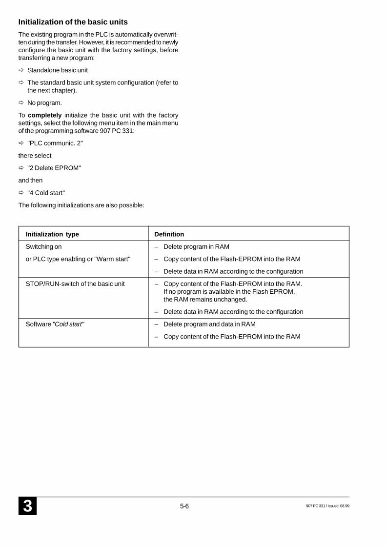
5-63 907 PC 331 / Issued: 08.99
Initialization of the basic unitsThe existing program in the PLC is automatically overwrit-ten during the transfer. However, it is recommended to newlyconfigure the basic unit with the factory settings, beforetransferring a new program:
� Standalone basic unit
� The standard basic unit system configuration (refer tothe next chapter).
� No program.
To completely initialize the basic unit with the factorysettings, select the following menu item in the main menuof the programming software 907 PC 331:
� "PLC communic. 2"
there select
� "2 Delete EPROM"
and then
� "4 Cold start"
The following initializations are also possible:
Initialization type Definition
Switching on – Delete program in RAM
or PLC type enabling or "Warm start" – Copy content of the Flash-EPROM into the RAM
– Delete data in RAM according to the configuration
STOP/RUN-switch of the basic unit – Copy content of the Flash-EPROM into the RAM.If no program is available in the Flash EPROM,the RAM remains unchanged.
– Delete data in RAM according to the configuration
Software "Cold start" – Delete program and data in RAM
– Copy content of the Flash-EPROM into the RAM


ABB Schalt- und Steuerungstechnik GmbHEppelheimer Straße 82 Postfach 10 50 09D-69123 Heidelberg D-69040 Heidelberg
Telephone +49 6221 777-0Telefax +49 6221 777-111E-Mail [email protected] http://www.abb-sst.de Printed in the Federal Republic of Germany (08.99)
Printed on chlorine-free bleached paper