ABB i-bus KNX DALI Gateway Emergency Lighting DGN… · ABB i-bus® KNX DALI Gateway Emergency...
166
ABB i-bus ® KNX DALI Gateway Emergency Lighting DGN/S 1.16.1 Product Manual
Transcript of ABB i-bus KNX DALI Gateway Emergency Lighting DGN… · ABB i-bus® KNX DALI Gateway Emergency...
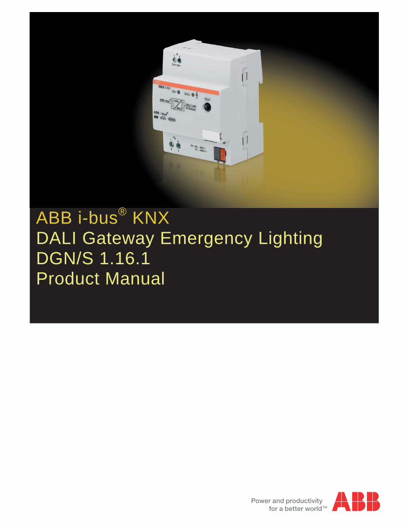
ABB i-bus® KNX DALI Gateway Emergency Lighting DGN/S 1.16.1 Product Manual

ABB i-bus® KNX Contents
DGN/S 1.16.1 | 2CDC 507 114 D0201 i
Contents Page
1 General ................................................................................................. 31.1 Product and functional overview...................................................................................................41.2 DALI general.................................................................................................................................61.3 ABB i-bus® DALI-Gateway in comparison ....................................................................................71.3.1 DGN/S 1.16.1 system description (group control) ........................................................................81.3.2 DGN/S 1.16.1 emergency lighting test .......................................................................................101.3.2.1 Function test ...............................................................................................................................101.3.2.2 Duration test ...............................................................................................................................101.3.2.3 Partial duration test.....................................................................................................................10
2 Device Technology ............................................................................ 112.1 Technical data ............................................................................................................................122.2 Circuit diagram ...........................................................................................................................142.3 Dimension drawing .....................................................................................................................152.4 Assembly and installation ...........................................................................................................162.5 Description of the inputs and outputs .........................................................................................182.6 Manual operation........................................................................................................................192.6.1 Display elements ........................................................................................................................20
3 Commissioning.................................................................................. 213.1 Overview ....................................................................................................................................223.1.1 Conversion of previous application program versions ................................................................243.1.1.1 Procedure...................................................................................................................................253.2 Parameters .................................................................................................................................263.2.1 Parameter window General ........................................................................................................273.2.2 Parameter window Central .........................................................................................................323.2.2.1 Parameter window - Emergency.................................................................................................393.2.2.2 Parameter window - Status ........................................................................................................423.2.2.3 Parameter window Gx Group .....................................................................................................513.2.2.4 Parameter window – Gx Status ..................................................................................................603.2.2.5 Parameter window – Gx Fault ....................................................................................................643.2.2.6 Parameter window – Gx Slave emergency.................................................................................683.2.2.7 Parameter window - Gx Slave ....................................................................................................703.2.2.8 Parameter window - Gx Sequence .............................................................................................743.2.2.9 Parameter window - Gx Staircase lighting ..................................................................................773.2.3 Parameter window Scenes .........................................................................................................843.2.4 Parameter window Scene x ........................................................................................................853.2.5 Parameter window Sequence.....................................................................................................873.2.6 Parameter window Emergency Converter ..................................................................................903.2.6.1 Parameter window Cx…Cy Converter ........................................................................................923.2.6.2 Parameter window - Cx…Cy Test ..............................................................................................953.3 Communication objects ..............................................................................................................983.3.1 Brief overview of the communication objects..............................................................................993.3.2 Communication objects General...............................................................................................1013.3.3 Communication objects DALI output ........................................................................................1023.3.4 Communication objects Group x...............................................................................................1183.3.5 Communication objects Fault ...................................................................................................1203.3.6 Communication objects Converter x.........................................................................................1223.3.7 Communication objects Scene x/y............................................................................................1243.3.8 Communication objects function Slave .....................................................................................1263.3.9 Communication objects function Sequence..............................................................................1273.3.10 Communication objects function Staircase lighting...................................................................128
4 Planning and Application................................................................ 1294.1 Automatic DALI addressing ......................................................................................................1294.2 Function chart...........................................................................................................................1304.3 Monitoring of lamps and ballasts ..............................................................................................131
ABB i-bus® KNX Contents
ii 2CDC 507 114 D0201 | DGN/S 1.16.1
4.4 Exchange of DALI devices....................................................................................................... 1324.5 Burning-in of luminaries ........................................................................................................... 1334.6 Staircase lighting ..................................................................................................................... 1344.7 Scene ...................................................................................................................................... 1364.8 Slave........................................................................................................................................ 1394.9 Sequence................................................................................................................................. 1424.10 DALI lighting curve................................................................................................................... 1474.10.1 Characteristic adjustment of the linear dimming curve ............................................................ 1494.10.2 Characteristic adjustment with physical minimum dimming value............................................ 150
A Appendix...........................................................................................151A.1 Code table Fault group/device (no. 20).................................................................................... 151A.2 Code table 8 bit scene (no. 232).............................................................................................. 154A.3 Code table Diagnostics byte “request“ (no. 25)........................................................................ 155A.4 Code table Diagnostics byte “feedback“ (no. 25) ..................................................................... 156A.5 Further information about DALI................................................................................................ 158A.6 Scope of delivery ..................................................................................................................... 159A.7 Ordering Information................................................................................................................ 160A.8 DALI equipment ....................................................................................................................... 161A.9 Notes ....................................................................................................................................... 162
ABB i-bus® KNX General
DGN/S 1.16.1 | 2CDC 507 114 D0201 3
1 General
This manual provides you with detailed technical information relating to the group-orientated ABB i-bus® KNX DALI Gateway with Emergency Lighting Function DGN/S 1.16.1. The installation, programming and commissioning and the device are described using examples. Furthermore, basic terminology used with emergency lighting technology is explained.
The DGN/S is used for control of DALI equipment, e.g. ballasts, transformers or LED converters with DALI interfaces compliant to EN 62386 via KNX. Furthermore, DALI self-contained emergency lighting (device type 1) with individual batteries can be integrated to EN 62386-202.
Here the DGN/S 1.16.1 itself does not offer a functionality in terms of the emergency lighting regulations, e.g. protocoling functions or other associated stipulated functions. It serves as an intelligent mediator be-tween KNX and DALI.
The different mandatory tests for emergency lighting, e.g. functional tests or duration testing, can be trig-gered via KNX, and the result can be provided again on the KNX via communication objects.
The DGN/S combines both the internationally standardized and open standards in the digital illumination control DALI (EN 62386) and intelligent installation system KNX (ISO/IEC 14543-3 and EN 50090).
ABB i-bus® KNX General
4 2CDC 507 114 D0201 | DGN/S 1.16.1
1.1 Product and functional overview
The group-orientated KNX DALI Gateway DGN/S 1.16.1 is a modular installation device in ProM design. Up to 64 DALI devices can be connected to a DALI output. These 64 DALI devices can be divided into up to 16 lighting groups. Every lighting group can be independently switched, dimmed and a brightness value can be set via the KNX. For each group, a KNX communication object is available for indicating a lamp, ballast or the combination of lamp and ballast fault on the KNX. The fault status of an individual device can also be signalled or queried via coded communication objects. Furthermore, the functions Scene (up to 14), Staircase lighting, Slave and Sequence are available.
The special feature of the DGN/S 1.16.1 is that DALI emergency lighting converters can also be connected as DALI devices. A DALI emergency lighting converter is a DALI device, which monitors and tests the sta-te of an individual battery of an emergency lighting device and that provides the information via standard-ized DALI telegrams compliant to EN 62 386-202. The DALI Gateway with Emergency Lighting Function DGN/S 1.16.1 evaluates this information and sends it on the KNX.
A self-contained emergency lighting can have
two DALI devices (ballast and emergency lighting converter) or
one DALI device, which features the function of the emergency lighting converter and the control of the lighting equipment, usually LEDs.
In the first case, the DGN/S 1.16.1 controls a maximum of 32 emergency lights, as the DALI standard lim-its the number of DALI devices to 64 DALI devices. In the second case, DALI emergency lighting convert-ers with two functions as a DALI device can connect up to 64 emergency lights to the DGN/S.
Access to the individual devices for the determined individual functionalities is possible. In the case of mo-nitoring of individual lamps or batteries, the information is available as coded KNX telegrams that are up to 4 bytes in length.
The DGN/S 1.16.1 does not support overlapping DALI lighting groups. Cross-lighting groups should be formed by KNX group addressing. Furthermore, it is possible to commonly control all DALI devices con-nected to a DALI output via DALI output telegrams (DALI broadcast control).
The DALI power supply for the 64 DALI devices is integrated into the DGN/S 1.16.1.
Readdressing of the DALI devices and the assignment of the 64 DALI devices into 16 lighting groups is implemented in an ETS independent DALI-Software-Tool, so that for example, a facility manager without ETS knowledge is capable of exchanging and reassigning DALI devices, should maintenance be required. Furthermore, the error states of the individual DALI devices and/or lighting groups are represented graphi-cally with the DALI-Software-Tool.
The setting of the parameters and allocation of the group addresses is implemented primarily with the En-gineering Tool Software ETS. The most up-to-date version should be used. The minimum requirement is version ETS2 V1.3.
ABB i-bus® KNX General
DGN/S 1.16.1 | 2CDC 507 114 D0201 5
The application program offers a range of functions:
Switching, dimming, setting of brightness values
Status feedbacks via common or separate communication objects
Status response of a lamp and/or ballast malfunction
Programming of individual maximum and minimum dimming limit values (dimming thresholds)
Different dimming speeds for switching, setting brightness values and dimming
Reaction at DALI and KNX voltage failure and recovery
Programming of the brightness value (power ON level) after a ballast operating voltage recovery
KNX control of all connected DALI devices without prior commissioning (DALI group assignment)
Triggering of the emergency lighting test via a DALI emergency lighting converter
Function test
Duration test
Partial duration test
Battery charge state
Transfer of the emergency lighting test results to the KNX
Various operating modes, e.g.:
Function Slave for integration of the lighting groups in an energy efficient lighting control
14 independent light scenes, which can be recalled or stored via 1 bit or 8 bit telegrams
Function Staircase lighting including pre-warning
Function Sequence for programming of running lights or colour effects
ABB i-bus® KNX General
6 2CDC 507 114 D0201 | DGN/S 1.16.1
1.2 DALI general
The requirements for modern lighting technology are extremely varied. While previously lighting was only required for visual tasks, nowadays factors such as comfort, ambience, functionality and energy efficiency are in the foreground. Furthermore, a modern lighting system is increasingly being incorporated into the facility management of the building installation in order to monitor the status of the entire lighting system. Often, a complex lighting management system is needed, which meets the uses of the premises. All these requirements are either not adequately met by the traditional 1–10 V electrical installation or only with con-siderable effort and cost. The DALI standard (EN 60929 previously EN 62386) has emerged against this background in conjunction with leading manufacturers of lamp ballasts. It describes and defines the digital interface DALI (Digital Addressable Lighting Interface) for lighting technology equipment.
DALI has become established as an independent standard in the field of lighting technology. The range of ballasts, transformers, dimmers and relays with DALI interfaces has decisively influenced modern lighting technology.
Part 202 of DALI standard 62386 described DALI commands to communicate with emergency converters. With this DALI commands emergency test (e.g. function test, duration test, and battery capacity informa-tion) can be triggered. The test result will send back from the emergency converter to DALI and over the DGN/S to KNX.
This KNX DALI technique allows a management building system to trigger the demanded emergency tests and documented the test results.
More detailed information concerning the DALI can be found in the manuals DALI Gateway DGN/S 1.16.1, The DALI Manual or the DALI, Manual of DALI AG, which is part of the ZVEI.

ABB i-bus® KNX General
DGN/S 1.16.1 | 2CDC 507 114 D0201 7
1.3 ABB i-bus® DALI-Gateway in comparison
ABB Stotz Kontakt GmbH currently has different KNX DALI-Gateway devices in the ABB i-bus® range, for integration of DALI interfaces into a KNX building installation. Every DALI Gateway has benefits that can be specifically utilised on different project types.
These differences are described in the following.
The differences are listed briefly below in the table. A detailed description can be found in the chapters that follow.
Property DG/S 8.1 Control Central
DG/S 1.1 Control Individual
DG/S 1.16.1 Control Group
DGN/S 1.16.1 Control Group
Design MDRC MDRC MDRC MDRC Mounting width 6 4 4 4 DALI outputs 8 (A…H) 2 (A & B) 1 (A) 1 (A)
DALI device (ballast) per Gateway
128 (max.16 per output)
128 (max. 64 per output)
64
64 (ballasts and emergency lighting converter)
DALI emergency lighting converter - - - 64
Lighting groups per Gateway 8 (installation) A: max. 255 (KNX) B: 1
16*) (DALI) 16 (DALI)
Lighting groups established via
cable installation A: KNX B: cable installation
DALI DALI
DALI devices (e.g. ballasts) per lighting group
max. 16 A: max. 64 B: max. 64
Max. 64 Max. 64
DALI addressing not required A: 64 individual B: 64 individual
64 individual 64 individual
Number of DALI telegrams per KNX telegram of the group 1 telegram
A: max. 64 telegrams B: 1 telegram
1 telegram per group
1 telegram per group
Power supply to the KNX processor via KNX KNX KNX KNX
DALI voltage integrated power supply
integrated power supply
integrated power supply
integrated power supply
*) The 16th lighting group can also be used internally as an option. The DGN/S 1.16.1 assigns the DALI devices, that do not belong to any other lighting group, to group 16. In this way, commissioning of all devices using the KNX via the communi-cation objects DALI output is also possible without prior group assignment.
ABB i-bus® KNX General
8 2CDC 507 114 D0201 | DGN/S 1.16.1
1.3.1 DGN/S 1.16.1 system description (group control)
The KNX/DALI Gateway DGN/S 1.16.1 with emergency lighting function is primarily a “normal” DALI Ga-teway with group control. However, additional DALI devices for self-contained emergency lighting (device type 1) with individual batteries compliant to the DALI standard EN 62386-202 are supported. Up to 64 DALI devices can be connected to a DALI output. DALI emergency lighting devices and normal DALI de-vices can be combined as required. An emergency light can consist of two separate DALI devices or also of just one individual device:
Two separate DALI devices:
1 ballast (DALI device 1) for normal lighting. It assumes the control of the lighting equipment in normal operation.
1 emergency lighting converter (DALI device 2), which controls the lighting equipment in emergency lighting operation. Generally, the emergency lighting converter disconnects the normal ballast in emergency lighting operation and autonomously assumes control of the emergency lighting. The emergency lighting converter will switch back to the normal ballast only after emergency lighting op-eration has ended.
One DALI device:
1 combined emergency lighting converter, which assumes the control of the lighting equipment in normal and in emergency lighting operation. Usually, they are LED based solutions.
If battery-operated emergency lighting contains two DALI devices (a ballast and a converter, each with a DALI interface), up to 32 battery operated emergency lights can be connected. The DALI Gateway auto-matically recognizes whether the connected DALI device is a battery operated emergency converter and thus an emergency lighting device (device type 1) compliant to EN 62386-202. This information is indi-cated by the DALI-Software-Tool. It is possible that both “normal” lamps as well as battery operated emer-gency lighting are connected in a mixed configuration to the DGN/S 1.16.1. However, the maximum per-mitted number of 64 DALI devices may not be exceeded.
Self tests of every individual emergency lighting converter is started by request via the KNX. The test re-sult is reported via the KNX. The communication object Emergency test trigger starts the emergency light-ing test (function test, short duration test or duration test) or queries emergency lighting tests already un-der way. The test result is automatically sent via the 4 byte communication object Emergency test result.
Via the communication object Slave emergency active/status, all the lamps in a group controlled by the DGN/S to the parameterized Brightness value are set. This is independent of whether the lamps them-selves are affected by an emergency lighting operating voltage failure, mains voltage failure or DALI volt-age failure. The response during the emergency lighting operation activated by the DALI Gateway can be parameterized. The prerequisite is that the DGN/S is supplied by the DALI operating voltage.
The Slave emergency is not tripped by a voltage failure. It is triggered by DGN/S if a parameterised num-ber of lamp or ballast failures exist.
Note
During emergency lighting operation, the DALI devices cannot be commissioned.
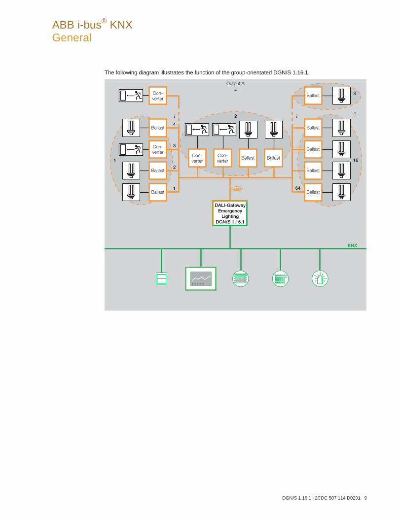
ABB i-bus® KNX General
DGN/S 1.16.1 | 2CDC 507 114 D0201 9
The following diagram illustrates the function of the group-orientated DGN/S 1.16.1.
Output A
...
... ...
1
3
2
16
KNX
Ballast
Ballast
Ballast
Ballast
Ballast
Con-
verter
Con-
verterBallast Ballast
Ballast
Ballast
Con-
verter
Ballast
Con-
verter
1
2
3
4
64
DALI-GatewayEmergency
LightingDGN/S 1.16.1
...
ABB i-bus® KNX General
10 2CDC 507 114 D0201 | DGN/S 1.16.1
1.3.2 DGN/S 1.16.1 emergency lighting test
The DGN/S 1.16.1 serves as a gateway for self-contained emergency lighting systems and KNX building management. On this way it is possible to controlled and monitored DALI-based emergency self-contained lighting devices (converters) compliant with IEC 62 386-202.
A DALI device to IEC 62 386-202 (Device type 1), for self-contained emergency lighting with individual bat-teries, is described in this manual in shortened form as an emergency lighting converter.
The DGN/S 1.16.1 itself does not offer functionality in terms of the emergency lighting regulations, e.g. protocoling functions or other associated stipulated functions. It is used exclusively as a gateway between the KNX communication objects and the DALI commands.
The different mandatory tests for emergency lighting are controlled by KNX communication objects. The test sequence is subsequently monitored by KNX communication objects, and the results are signalled by further communication objects on the KNX.
A further possibility is the use of an automated test interval that is controlled by the DALI emergency light-ing converter itself. The interval duration is determined by the KNX parameter. KNX communication ob-jects transfer the results.
1.3.2.1 Function test
The function test is undertaken by the emergency lighting converter itself. The function test is requested at a parameterizable interval in the emergency lighting converter or by a KNX communication object. The functional security of the emergency lighting converter electronics and correct operation of a lamp and a switch-over device for an individual battery are tested.
1.3.2.2 Duration test
The duration test is implemented on the basis of the IEC 62 386-202 and is used to determine whether the individual battery of the system is within the limits of the rated operating duration in emergency lighting op-eration.
1.3.2.3 Partial duration test
The partial duration test is controlled with the aid of the duration test of the DALI device by the Gateway. This is possible as a partial duration test is not stipulated or described by the standards. It simply offers an additional and enhanced possibility for operation readiness of emergency lighting in a simple and time-efficient way without completely discharging the battery.
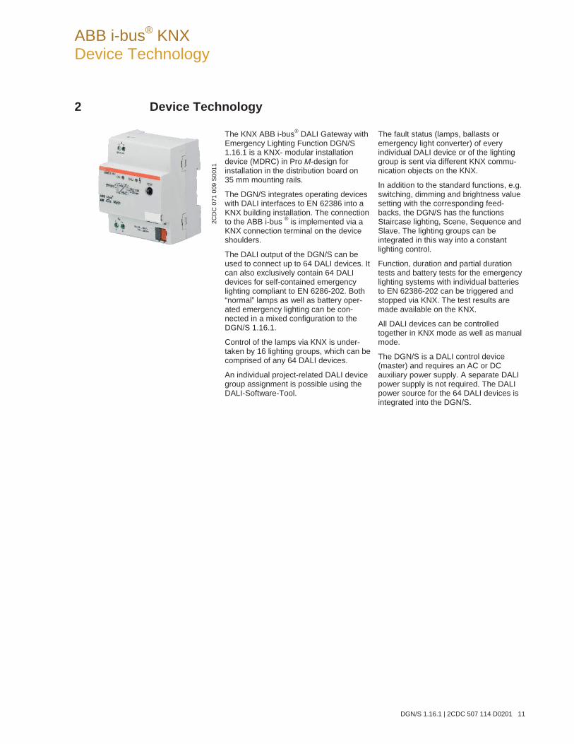
ABB i-bus® KNX Device Technology
DGN/S 1.16.1 | 2CDC 507 114 D0201 11
2 Device Technology
The KNX ABB i-bus® DALI Gateway with Emergency Lighting Function DGN/S 1.16.1 is a KNX- modular installation device (MDRC) in Pro M-design for installation in the distribution board on 35 mm mounting rails.
The DGN/S integrates operating devices with DALI interfaces to EN 62386 into a KNX building installation. The connection to the ABB i-bus ® is implemented via a KNX connection terminal on the device shoulders.
The DALI output of the DGN/S can be used to connect up to 64 DALI devices. It can also exclusively contain 64 DALI devices for self-contained emergency lighting compliant to EN 6286-202. Both “normal” lamps as well as battery oper-ated emergency lighting can be con-nected in a mixed configuration to the DGN/S 1.16.1.
Control of the lamps via KNX is under-taken by 16 lighting groups, which can be comprised of any 64 DALI devices.
An individual project-related DALI device group assignment is possible using the DALI-Software-Tool.
The fault status (lamps, ballasts or emergency light converter) of every individual DALI device or of the lighting group is sent via different KNX commu-nication objects on the KNX.
In addition to the standard functions, e.g. switching, dimming and brightness value setting with the corresponding feed-backs, the DGN/S has the functions Staircase lighting, Scene, Sequence and Slave. The lighting groups can be integrated in this way into a constant lighting control.
Function, duration and partial duration tests and battery tests for the emergency lighting systems with individual batteries to EN 62386-202 can be triggered and stopped via KNX. The test results are made available on the KNX.
All DALI devices can be controlled together in KNX mode as well as manual mode.
The DGN/S is a DALI control device (master) and requires an AC or DC auxiliary power supply. A separate DALI power supply is not required. The DALI power source for the 64 DALI devices is integrated into the DGN/S.
2CD
C 0
71 0
09 S
0011
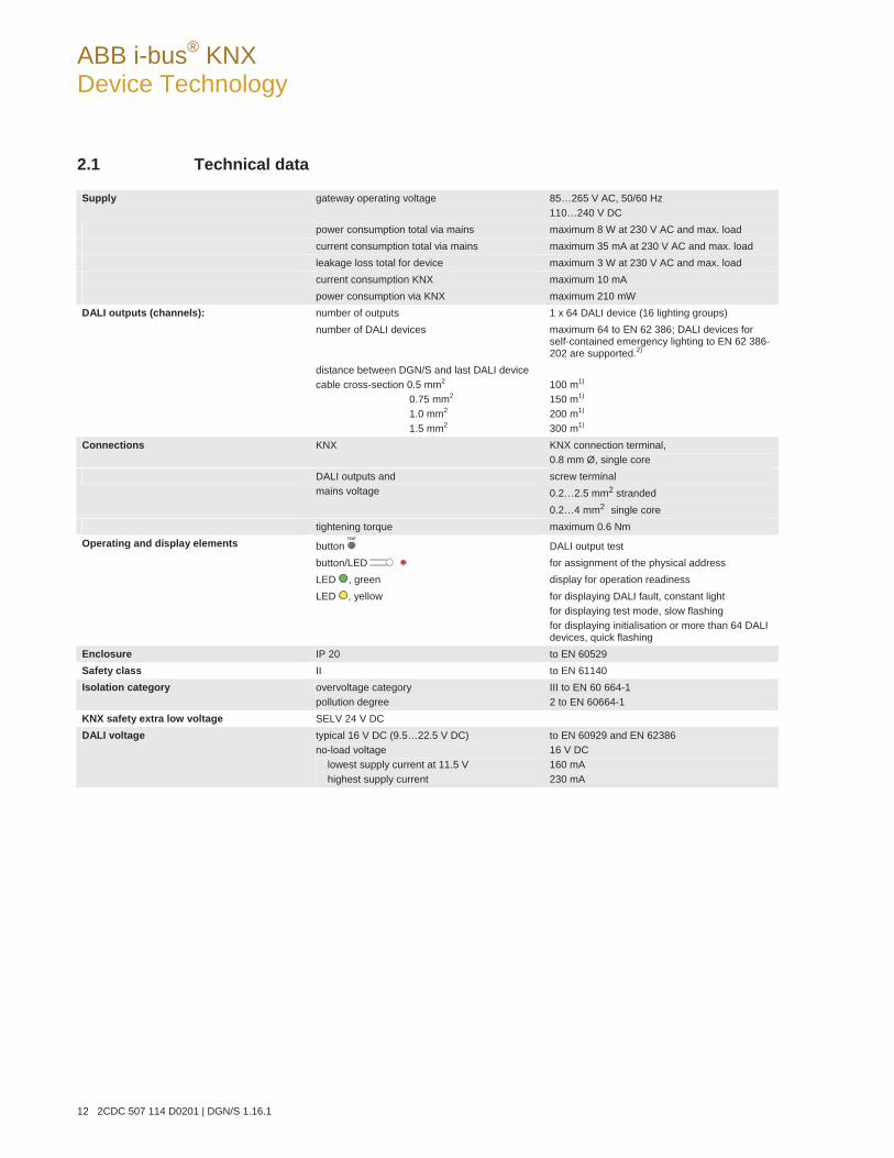
ABB i-bus® KNX Device Technology
12 2CDC 507 114 D0201 | DGN/S 1.16.1
2.1 Technical data
Supply gateway operating voltage 85…265 V AC, 50/60 Hz 110…240 V DC
power consumption total via mains maximum 8 W at 230 V AC and max. load current consumption total via mains maximum 35 mA at 230 V AC and max. load leakage loss total for device maximum 3 W at 230 V AC and max. load current consumption KNX maximum 10 mA power consumption via KNX maximum 210 mW
DALI outputs (channels): number of outputs 1 x 64 DALI device (16 lighting groups) number of DALI devices maximum 64 to EN 62 386; DALI devices for
self-contained emergency lighting to EN 62 386-202 are supported.2)
distance between DGN/S and last DALI device cable cross-section 0.5 mm2 0.75 mm2 1.0 mm2 1.5 mm2
100 m1) 150 m1) 200 m1) 300 m1)
Connections KNX KNX connection terminal, 0.8 mm Ø, single core
DALI outputs and mains voltage
screw terminal 0.2…2.5 mm2 stranded 0.2…4 mm2 single core
tightening torque maximum 0.6 Nm Operating and display elements button DALI output test
button/LED for assignment of the physical address LED , green display for operation readiness LED , yellow for displaying DALI fault, constant light
for displaying test mode, slow flashing for displaying initialisation or more than 64 DALI devices, quick flashing
Enclosure IP 20 to EN 60529 Safety class II to EN 61140 Isolation category overvoltage category
pollution degree III to EN 60 664-1 2 to EN 60664-1
KNX safety extra low voltage SELV 24 V DC DALI voltage typical 16 V DC (9.5…22.5 V DC)
no-load voltage lowest supply current at 11.5 V highest supply current
to EN 60929 and EN 62386 16 V DC 160 mA 230 mA

ABB i-bus® KNX Device Technology
DGN/S 1.16.1 | 2CDC 507 114 D0201 13
Temperature range operation -5 °C…+45 °C storage -25 °C…+55 °C transport -25 °C…+70 °C
Environmental conditions humidity maximum 93 %, moisture condensation should be excluded
Design modular installation device (MDRC) modular installation device, ProM dimensions 90 x 72 x 64.5 mm (H x W x D) mounting width 4 modules at 18 mm mounting depth 68 mm
Installation on 35 mm mounting rail to EN 60 715 Mounting position as required Weight 0.16 kg Housing, colour plastic housing, grey Approvals KNX to EN 50 090-1, -2 certification CE mark in accordance with the EMC guideline and low
voltage guideline
1) The length relates to the common DALI control cable. The maximum values are rounded off and relate to the resistance values. EMC influences are not considered. For this reason, the values should be considered as absolute maximum values.
2) Both “normal” lamps as well as battery operated emergency lighting can be connected in a mixed configuration to the DGN/S 1.16.1. However, the maximum number of DALI devices may not exceed 64.
Device type Application program Maximum number of
communication objects Maximum number of group addresses
Maximum number of associations
DGN/S 1.16.1 Switch Dim Emergency 1f DALI/…*
246 254 255
* … = current version number of the application program. Please observe the software information on our homepage for this purpose.
Note
The DGN/S is compliant to the SELV characteristics to IEC 60 364-4-41 (VDE 0100-410). DALI does not need to feature SELV properties, and it is possible to route the DALI control lines to-gether with the mains voltage on a multi-core cable.
Note
The ETS and the current version of the device application program are required for programming. The current version of the application program is available for download on the internet at www.abb.com/knx. After import in the ETS, it is available in the ETS under ABB//Lighting/ DALI/ Switch Dim Emergency 1f DALI. The device does not support the closing function of a KNX device in the ETS. If you inhibit access to all devices of the project with a BCU code, it has no effect on this device. Reading out data and program-ming is still possible.
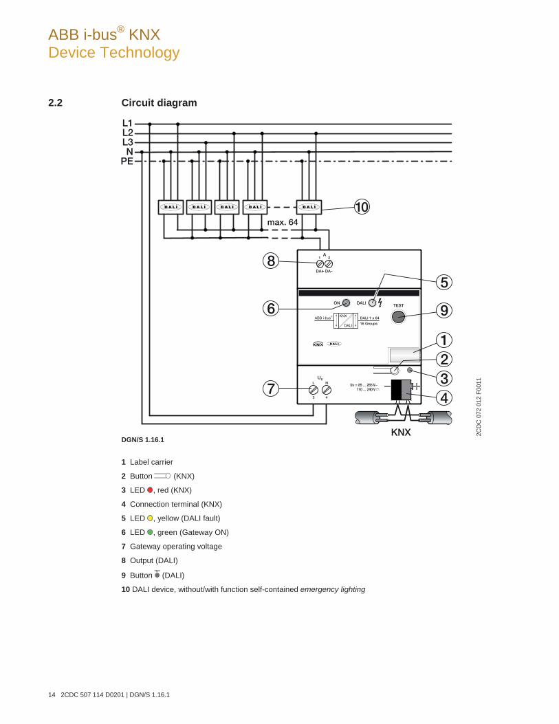
ABB i-bus® KNX Device Technology
14 2CDC 507 114 D0201 | DGN/S 1.16.1
2.2 Circuit diagram
DGN/S 1.16.1
1 Label carrier
2 Button (KNX)
3 LED , red (KNX)
4 Connection terminal (KNX)
5 LED , yellow (DALI fault)
6 LED , green (Gateway ON)
7 Gateway operating voltage
8 Output (DALI)
9 Button (DALI)
10 DALI device, without/with function self-contained emergency lighting
2CD
C 0
72 0
12 F
0011
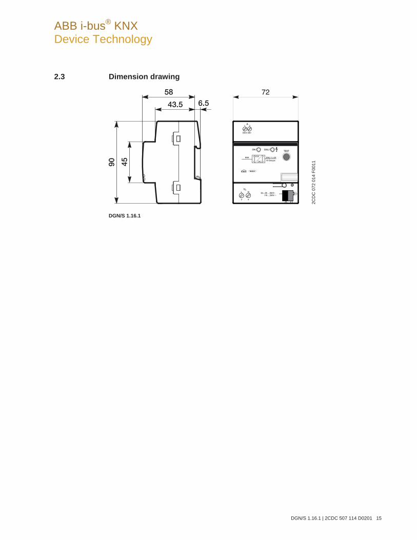
ABB i-bus® KNX Device Technology
DGN/S 1.16.1 | 2CDC 507 114 D0201 15
2.3 Dimension drawing
DGN/S 1.16.1
2CD
C 0
72 0
14 F
0011
ABB i-bus® KNX Device Technology
16 2CDC 507 114 D0201 | DGN/S 1.16.1
2.4 Assembly and installation
The device is a modular installation device for quick installation in the distribution board on 35 mm mount-ing rails to EN 60 715. The mounting position can be selected as required.
The electrical connection is implemented using screw terminals. The connection to the KNX is imple-mented using the supplied KNX connection terminal. The terminal assignment is located on the housing.
The device is ready for operation after connection to the KNX voltage and the gateway operating voltage.
Accessibility of the devices for the purpose of operation, testing, visual inspection, maintenance and repair must be provided compliant to VDE 0100-520.
Commissioning requirements In order to commission the device, a PC with ETS and a KNX interface, e.g. USB or IP, are required. The device is ready to operate when the KNX voltage and the gateway operating voltage are applied.
The assignment of the DALI devices to the lighting groups as well as the configuration of the emergency lighting converter is undertaken with the DALI-Software-Tool.
The emergency lighting battery must be charged for commissioning of the DALI emergency lighting con-verter. Commissioning without emergency lighting operation is not possible.
Important
Acceptance of the emergency lighting monitoring must be discussed with the corresponding approval agency.
The installation and commissioning may only be carried out by qualified electrical specialists. The appro-priate norms, guidelines, regulations and specifications for your country should be observed when plan-ning and setting up electrical installations and security systems for intrusion and fire detection.
Protect the device from damp, dirt and damage during transport, storage and operation.
Only operate the device within the specified technical data limits!
The device should only be operated in an enclosed housing (distribution board)!
The voltage supply to the device must be switched off, before mounting work is performed.
Manual operation The device incorporates manual operating features. The device features a button for manual switching of the DALI output.
ABB i-bus® KNX Device Technology
DGN/S 1.16.1 | 2CDC 507 114 D0201 17
Supplied state The device is supplied with the physical address 15.15.255. The application program is preloaded. It is therefore only necessary to load group addresses and parameters during commissioning.
However, the complete application program can be reloaded if required. A longer downtime may result if the application program is changed or after a discharge.
Assignment of the physical address The assignment and programming of the physical address is carried out in the ETS.
The device features a button for assignment of the physical device address. The red LED lights up, after the button has been pushed. It switches off as soon as the ETS has assigned the physical address or the button is pressed again.
Download response Depending on the PC, which is used, the progress bar for the download may take up to one and a half mi-nutes, before it appears, due to the complexity of the device.
Cleaning If devices become dirty, they can be cleaned using a dry cloth or a cloth dampened with a soapy solution. Corrosive agents or solutions should never be used.
MaintenanceThe device is maintenance-free. No repairs should be carried out by unauthorised personnel if damage occurs, e.g. during transport and/or storage.
ABB i-bus® KNX Device Technology
18 2CDC 507 114 D0201 | DGN/S 1.16.1
2.5 Description of the inputs and outputs
On the DALI output up to 64 devices can be connected with a DALI interface. The DGN/S is a DALI master with integrated DALI power supply.
Important
Other DALI masters may not be connected to the output of the DGN/S. The connection of another master to the single master system can cause communication malfunctions.
CautionOther DALI power supplies may not be connected to the output of the DGN/S. The connection of further DALI supply voltages may destroy the DGN/S due to voltage summation. Connection of 230 V mains voltage to the DALI output will destroy the DALI end stage and the DALI output.
A control line on the DALI output with the following maximum length can be used:
Cable length [mm2] 2 x 0.5 2 x 0.75 2 x 1.0 2 x 1.5
Max. cable length [m] from the DGN/S to DALI device 100 150 200 300
These values are rounded off and relate to the resistance values. EMC influences are not considered. For this reason, the values should be considered as absolute maximum values.
It is possible to assemble the DALI control cable with conventional installation material for mains cables. The two cores of the five-core NYM 5 x 1.5 mm2, which are not required, can be used without considera-tion of the polarity. It is not mandatory to lay a separate control cable.
The isolation between DALI control cables and the power supply is assured by the simple insulation prop-erties according to EN 410. SELV properties are not featured.
The device is ready for operation after connection of the gateway operating voltage. The green operating LED on the front of the device lights up.
The yellow flashing (10 Hz) DALI LED indicates the maximum 90 second initialisation phase of the DGN/S. The DALI system environment is analysed in this phase. If required, new DALI devices are allocated a DALI address and can be assigned to a lighting group with the DALI-Software-Tool, whereby the lamps are integrated into the KNX building automation. During this phase, it cannot be guaranteed that an incom-ing telegram will be processed.
Note
The initialisation phase will not end if more than 64 DALI devices are connected.
The initialisation phase starts automatically after download, gateway operating voltage recovery and KNX voltage recovery. The initialisation phase is undertaken if in the parameterization Enable automatic DALI addressing has be-en deactivated.

ABB i-bus® KNX Device Technology
DGN/S 1.16.1 | 2CDC 507 114 D0201 19
2.6 Manual operation
The device features a button for manual switching of the DALI output. Manual operation is independent of KNX. The Gateway operating voltage and the DALI voltage must be available.
Switch on of manual operation:
Press button for longer than 2 seconds and less than 5 seconds. The green LED ON switches off. The yellow LED DALI flashes slowly (1 Hz). You are in manual operation. The brightness values set up to now are lost and are not set again after exiting manual operation. All DALI devices of the DALI output switch to 100% brightness.
Switching of the DALI output during manual operation:
Press button briefly (< 2 seconds). All DALI devices of the DALI output change their brightness state from ON to OFF or from OFF to ON.
Switch off of manual operation:
You are in manual operation. Press button for longer than 2 seconds and less than 5 seconds. The green LED ON switches on. The yellow LED DALI switches off. Manual operation is ended. The brightness level of the DALI output set in manual operation is retained.
Detection of DALI devices via button :
Press button for longer than five seconds. The current mode is not exited, and detection of DALI devices is triggered. The current state of the system is stored as the reference state. If the number of available DALI devices is reduced in the future or the type (emergency lighting converter/normal DALI device) of the DALI device has changed, the DGN/S assumes a ballast fault. The detection can also be activated via the KNX with communication object (no. 28) Detect ballasts.
The manual operation incl. Detect DALI devices can be inhibited and enabled via the communication ob-ject Manual operation block/status (no. 1). The status of whether manual operation is blocked can be re-quested via the same communication object. After a KNX or gateway operating voltage failure, manual op-eration is re-enabled.
Note
Test mode is ended automatically, if a button is not pressed within five minutes. The brightness values set in the test mode are retained. The full functionality of test mode is assured as soon as the initialisation phase of the DGN/S is com-plete. The initialization phase is recognizable by fast flashing (10 Hz) of the yellow LED DALI. The initialization phase starts after gateway operation and KNX voltage recovery or a download.
ABB i-bus® KNX Device Technology
20 2CDC 507 114 D0201 | DGN/S 1.16.1
2.6.1 Display elements
Two indicator LEDs are located on the front of the DGN/S:
ON DALI
ON The LED lights up if the gateway operating voltage is available and the device is ready for operation.
The LED is off should the gateway operating voltage fail. At the same time, a DALI voltage is not gen-erated. The DGN/S 1.16.1 is still programmable via the KNX. Control of the connected DALI device is no longer possible.
DALI The LED is off if the device is in normal mode.
The LED lights up if there is a DALI fault. A DALI fault is a DALI short circuit, a lamp or a ballast fault.
The LED flashes slowly (1 Hz) if the device is in test mode.
The LED flashes quickly (10 Hz) during the initialisation phase. The initialisation phase starts after download, KNX voltage recovery or after elimination of a DALI short circuit. The initialisation phase may take up to 90 seconds depending on the number of DALI devices. If more than 64 DALI devices are connected to a DALI output, the device will not exit the initialisation phase. The yellow LED will continuously flash. An undefined state can be indicated in the DALI-Software-Tool.
ABB i-bus® KNX Commissioning
DGN/S 1.16.1 | 2CDC 507 114 D0201 21
3 Commissioning
The parameterization of the DGN/S is implemented with the application program Switch Dim Emergency 1f DALI/1 and the Engineering Tool Software ETS.
The application program can be found in the ETS at ABB/Lighting/DALI.
The following work must be carried out:
Assignment of the physical KNX device address (ETS)
Optional re-addressing of the DALI devices (DALI-Software-Tool)
Assignment of the DALI devices to lighting groups represented in the KNX. Assignment is undertaken using the DALI-Software-Tool.
Parameterization of the DGN/S (ETS)
For parameterization purposes, a PC or Laptop with ETS3 or higher and a connection to the KNX, e.g. via RS232, USB or IP interface, is required.
The DGN/S allocates each connected DALI device, which does not have a DALI address, with the first free DALI address. This automatic addressing can be prevented using a parameter in the ETS, see Parameter window General, page 27. Readdressing of the DALI devices and the assignment to any lighting group is also possible with the DALI-Software-Tool without using the ETS, whereby the DALI devices must already have a DALI address (0…63).
Note
The DGN/S can only control the lamps, which have a DALI address and that are assigned to a lamp group. The only exception is with manual control, which is activated using the button on the front of the device. In test mode, all DALI devices are switched, irrespective of whether they are assigned with a DALI address or assigned to a lighting group.
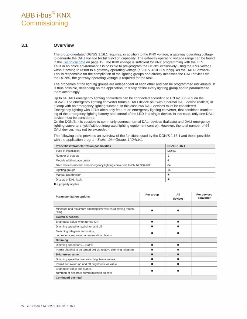
ABB i-bus® KNX Commissioning
22 2CDC 507 114 D0201 | DGN/S 1.16.1
3.1 Overview
The group-orientated DGN/S 1.16.1 requires, in addition to the KNX voltage, a gateway operating voltage to generate the DALI voltage for full function capability. The gateway operating voltage range can be found in the Technical data on page 12. The KNX voltage is sufficient for KNX programming with the ETS. Thus in an office environment it is possible to pre-program the DGN/S exclusively using the KNX voltage without having to resort to a gateway operating voltage (a 230 V AC/DC supply). As the DALI-Software-Tool is responsible for the compilation of the lighting groups and directly accesses the DALI devices via the DGN/S, the gateway operating voltage is required for the task.
The properties of the lighting groups are independent of each other and can be programmed individually. It is thus possible, depending on the application, to freely define every lighting group and to parameterize them accordingly.
Up to 64 DALI emergency lighting converters can be connected according to EN 62 386-202 on the DGN/S. The emergency lighting converter forms a DALI device pair with a normal DALI device (ballast) in a lamp with an emergency lighting function. In this case two DALI devices must be considered. Emergency lighting with LEDs often only feature an emergency lighting converter, that combines monitor-ing of the emergency lighting battery and control of the LED in a single device. In this case, only one DALI device must be considered. On the DGN/S, it is possible to commonly connect normal DALI devices (ballasts) and DALI emergency lighting converters (with/without integrated lighting equipment control). However, the total number of 64 DALI devices may not be exceeded.
The following table provides an overview of the functions used by the DGN/S 1.16.1 and those possible with the application program Switch Dim Groups 1f DALI/1.
Properties/Parameterization possibilities DGN/S 1.16.1 Type of installation MDRC
Number of outputs 1
Module width (space units) 4
DALI devices (normal and emergency lighting converters to EN 62 386-202) 64
Lighting groups 16
Manual test function
Display of DALI fault = property applies
Parameterization options
Per group All devices
Per device / converter
Minimum and maximum dimming limit values (dimming thresh-olds)
Switch functions
Brightness value when turned ON
Dimming speed for switch on and off
Switching telegram and status, common or separate communication objects
Dimming
Dimming speed for 0…100 %
Permit channel to be turned ON via relative dimming telegram
Brightness value
Dimming speed for transition brightness values
Permit set switch on and off brightness via value
Brightness value and status, common or separate communication objects
Continued overleaf
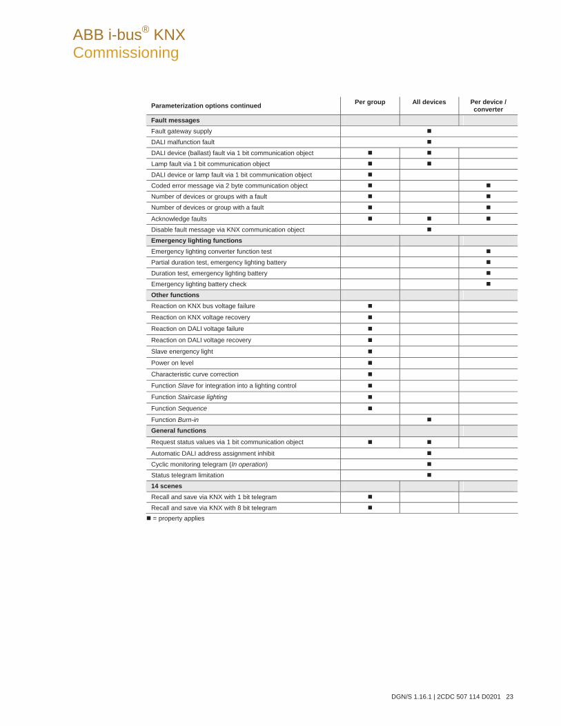
ABB i-bus® KNX Commissioning
DGN/S 1.16.1 | 2CDC 507 114 D0201 23
Parameterization options continued Per group All devices Per device / converter
Fault messages
Fault gateway supply
DALI malfunction fault
DALI device (ballast) fault via 1 bit communication object
Lamp fault via 1 bit communication object
DALI device or lamp fault via 1 bit communication object
Coded error message via 2 byte communication object
Number of devices or groups with a fault
Number of devices or group with a fault Acknowledge faults
Disable fault message via KNX communication object
Emergency lighting functions
Emergency lighting converter function test
Partial duration test, emergency lighting battery
Duration test, emergency lighting battery
Emergency lighting battery check
Other functions
Reaction on KNX bus voltage failure Reaction on KNX voltage recovery Reaction on DALI voltage failure Reaction on DALI voltage recovery Slave energency light Power on level Characteristic curve correction Function Slave for integration into a lighting control Function Staircase lighting Function Sequence Function Burn-in
General functions Request status values via 1 bit communication object Automatic DALI address assignment inhibit Cyclic monitoring telegram (In operation) Status telegram limitation 14 scenes
Recall and save via KNX with 1 bit telegram
Recall and save via KNX with 8 bit telegram = property applies
ABB i-bus® KNX Commissioning
24 2CDC 507 114 D0201 | DGN/S 1.16.1
3.1.1 Conversion of previous application program versions
For ABB i-bus® KNX devices from ETS3 or higher, it is possible to assume the parameter settings and group addresses from earlier application program versions.
Furthermore, conversion can be applied to transfer the existing parameterization of a device to another de-vice.
Note
When the term “channels” is used in the ETS, inputs and/or outputs are meant. In order to ensure that the ETS language generally applies for as many ABB i-bus® devices as possible, the word channels is used here.
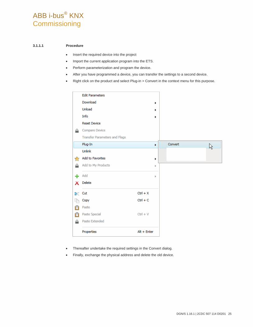
ABB i-bus® KNX Commissioning
DGN/S 1.16.1 | 2CDC 507 114 D0201 25
3.1.1.1 Procedure
Insert the required device into the project
Import the current application program into the ETS.
Perform parameterization and program the device.
After you have programmed a device, you can transfer the settings to a second device.
Right click on the product and select Plug-in > Convert in the context menu for this purpose.
Thereafter undertake the required settings in the Convert dialog.
Finally, exchange the physical address and delete the old device.
ABB i-bus® KNX Commissioning
26 2CDC 507 114 D0201 | DGN/S 1.16.1
3.2 Parameters
This chapter describes the parameters of the group-orientated DGN/S 1.16.1 based on the parameter win-dow. The parameter window features a dynamic structure so that further parameters or whole parameter windows may be enabled, depending on the parameterization and the function of the lighting groups.
In the following description, the group x or Gx (abbreviated form) represents all lighting groups of a DGN/S.
The default values of the parameters are underlined, e.g.
Option: yes no
Indented parameter descriptions indicate that this parameter is only visible when the main parameter is pa-rameterized accordingly.
Note
If in the following the communication objects Switch or Brightness value are mentioned, they also apply for the communication objects Switch/status or Brightness value/status.
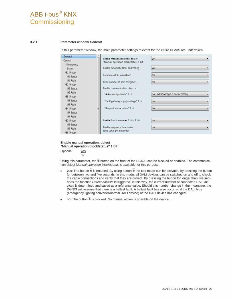
ABB i-bus® KNX Commissioning
DGN/S 1.16.1 | 2CDC 507 114 D0201 27
3.2.1 Parameter window General
In this parameter window, the main parameter settings relevant for the entire DGN/S are undertaken.
Enable manual operation. object "Manual operation block/status" 1 bit Options: yes
no
Using this parameter, the button on the front of the DGN/S can be blocked or enabled. The communica-tion object Manual operation block/status is available for this purpose
yes: The button is enabled. By using button the test mode can be activated by pressing the button for between two and five seconds. In this mode, all DALI devices can be switched on and off to check the cable connections and verify that they are correct. By pressing the button for longer than five sec-onds the function Detect ballasts is triggered. In this way, the current number of connected DALI de-vices is determined and saved as a reference value. Should this number change in the meantime, the DGN/S will assume that there is a ballast fault. A ballast fault has also occurred if the DALI type (emergency lighting converter/normal DALI device) of the DALI device has changed.
no: The button is blocked. No manual action is possible on the device.
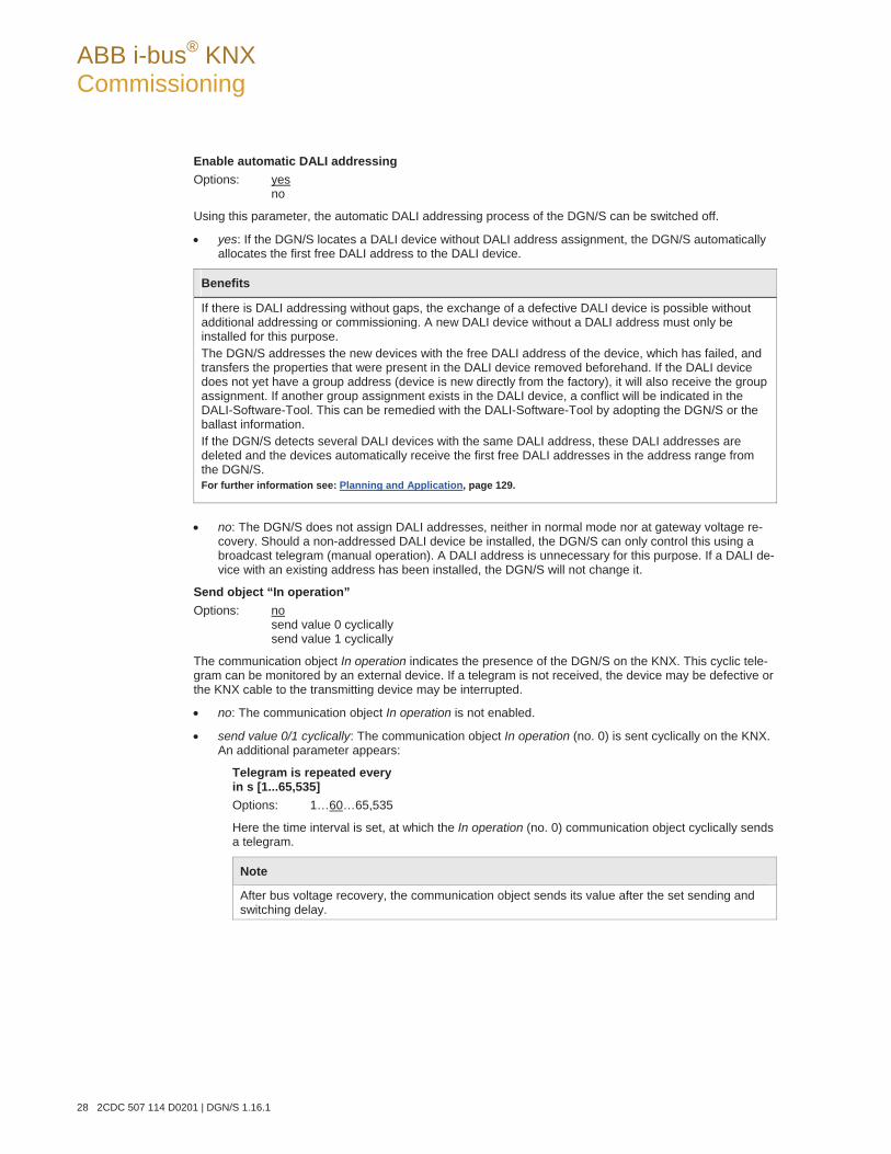
ABB i-bus® KNX Commissioning
28 2CDC 507 114 D0201 | DGN/S 1.16.1
Enable automatic DALI addressing Options: yes
no
Using this parameter, the automatic DALI addressing process of the DGN/S can be switched off.
yes: If the DGN/S locates a DALI device without DALI address assignment, the DGN/S automatically allocates the first free DALI address to the DALI device.
Benefits
If there is DALI addressing without gaps, the exchange of a defective DALI device is possible without additional addressing or commissioning. A new DALI device without a DALI address must only be installed for this purpose. The DGN/S addresses the new devices with the free DALI address of the device, which has failed, and transfers the properties that were present in the DALI device removed beforehand. If the DALI device does not yet have a group address (device is new directly from the factory), it will also receive the group assignment. If another group assignment exists in the DALI device, a conflict will be indicated in the DALI-Software-Tool. This can be remedied with the DALI-Software-Tool by adopting the DGN/S or the ballast information. If the DGN/S detects several DALI devices with the same DALI address, these DALI addresses are deleted and the devices automatically receive the first free DALI addresses in the address range from the DGN/S. For further information see: Planning and Application, page 129.
no: The DGN/S does not assign DALI addresses, neither in normal mode nor at gateway voltage re-
covery. Should a non-addressed DALI device be installed, the DGN/S can only control this using a broadcast telegram (manual operation). A DALI address is unnecessary for this purpose. If a DALI de-vice with an existing address has been installed, the DGN/S will not change it.
Send object “In operation” Options: no
send value 0 cyclically send value 1 cyclically
The communication object In operation indicates the presence of the DGN/S on the KNX. This cyclic tele-gram can be monitored by an external device. If a telegram is not received, the device may be defective or the KNX cable to the transmitting device may be interrupted.
no: The communication object In operation is not enabled.
send value 0/1 cyclically: The communication object In operation (no. 0) is sent cyclically on the KNX. An additional parameter appears:
Telegram is repeated every in s [1...65,535] Options: 1…60…65,535
Here the time interval is set, at which the In operation (no. 0) communication object cyclically sends a telegram.
Note
After bus voltage recovery, the communication object sends its value after the set sending and switching delay.
ABB i-bus® KNX Commissioning
DGN/S 1.16.1 | 2CDC 507 114 D0201 29
Limit number of sent telegrams Options: yes
no
The load on the KNX generated by the device can be limited with the limitation on the number of telegrams sent. This limit relates to all telegrams sent by the device.
yes: The following parameters appear:
Time between two response telegrams [1...255]Options: 1…20…255
in period Options: 50 ms/100 ms…1 s…30 s/1 min
This parameter defines the number of telegrams sent by the device within a period. The telegrams are sent as quickly as possible at the start of a period.
Note
The device counts the number of telegrams sent within a parameterized period. As soon as the maximum number of sent telegrams is reached, no further telegrams are sent on the KNX until the end of the period. A new period commences at the end of the previous period. The telegram counter is reset to zero, and sending of telegrams is allowed again. The current communication object value is always sent at the time of transmission. The first period (break time) is not predefined exactly. The period can be between zero seconds and the parameterized time. The subsequent sending times correspond with the parameterized time. Example: Maximum number of sent telegrams = 5, in period = 5 s. 20 telegrams are ready to be sent. The device immediately sends 5 telegrams. The next 5 telegrams are sent after maximum 5 seconds. From this point, a further 5 telegrams are sent on the KNX every 5 seconds.
Enable communication objects:
"Acknowledge faults" 1 bit Options: yes - acknowledgement is required
no - acknowledge is not necessary
Should a fault occur (ballast, lamps, DALI, operating supply voltage), the DGN/S sends a telegram via the respective communication object on the KNX.
yes - acknowledgement is required: First of all the communication object Acknowledge faults is enabled. As soon as the fault is rectified, a telegram with the value 0 is not sent automatically. This fault signal still remains set until the fault is rectified and the fault signal is reset via the communication object Acknowledge faults. Only then is a telegram with the value 0 sent via the corresponding communication object. This can be very helpful when detecting sporadic errors or events, which take place during unmanned monitoring periods.
no - acknowledge is not necessary: As soon as the fault is remedied, the DGN/S will reset the fault message and automatically send the status change in dependence on the parameteriza-tion to the communication object, e.g. Fault lamp. A telegram with the value 0 is sent. The change in the malfunction state may take 45 seconds and depends on the number of con-nected DALI devices.
ABB i-bus® KNX Commissioning
30 2CDC 507 114 D0201 | DGN/S 1.16.1
"Fault gateway supply voltage" 1 bit Option: yes
no
no: Failure of the gateway supply voltage is not reported to the KNX.
yes: The communication object Fault gateway supply is enabled. As soon as the device supply voltage is interrupted, the communication object Fault gateway supply sends a telegram with the value 1 on the KNX. The time, at which a telegram is sent, can be adjusted using the fol-lowing parameters.
send object value Options: after a change
after request after a change or request
after a change: The status is sent after a change.
after request: The status is sent after a request.
after a change or request: The status is sent after a change or a request.
"Request status values" 1 Bit Option: yes
no
Via this communication object, all status messages can be requested, provided that they have been parameterized with the option after a change or request or only after request.
yes: The 1 bit communication object Request status values is enabled. A further parameter ap-pears:
Request with object value Options: 0
1 0 or 1
0: Sending status messages is requested with the value 0.
1: Sending status messages is requested with the value 1.
0 or 1: Sending status messages is requested with the value 0 or 1.
ABB i-bus® KNX Commissioning
DGN/S 1.16.1 | 2CDC 507 114 D0201 31
Enable function scenes 1 bit / 8 bit Option: yes
no
This parameter enables the function Scenes and the corresponding parameter window Scenes. Up to 14 scenes are enabled here. Each of these 14 lighting scenes can be assigned to any of the 16 lighting groups.
Note
Generally, 16 scenes are available with DALI applications. Scenes 15 and 16 are, however, reserved for internal applications in the DGN/S.
yes: The parameter window Scenes is enabled.
Enable sequence time curve (one curve per gateway) Option: yes
no
The DGN/S offers the possibility of allowing a sequence to be run. A sequence is a string of up to a maxi-mum of ten scenes, which are recalled successively. In this way, it is possible to program running lights us-ing the DGN/S without additional logic or timer modules.
Note
Only one sequence can be programmed on the DGN/S. The setting is undertaken in the Parameter window Sequence, page 87. The sequence is recalled by the communication object Switch of the lighting groups which are members. This parameterization is undertaken in Parameter windowGx Group, page 51. For further information see: Sequence, page 142
yes: The parameter window Sequence is enabled.

ABB i-bus® KNX Commissioning
32 2CDC 507 114 D0201 | DGN/S 1.16.1
3.2.2 Parameter window Central
In this parameter window, the settings for simultaneous control of all lighting groups connected to the DALI output are parameterized.
Note
If a central telegram is referred to in the following, this is a telegram, which is received via one of the communication objects with the name DALI output. They are the communication objects no. 10 to 35. The function of the communication object relates to the complete DALI output with all connected DALI devices incl. emergency lighting converter. If at the time of the incoming central telegram an individual group telegram is implemented, this is immediately interrupted and the central telegram is executed on the DALI output. If all groups (devices) are controlled with a central telegram and if a subsequent telegram is received for a group, this group will execute the group telegram. The telegram received last has a higher priority and is executed.
ABB i-bus® KNX Commissioning
DGN/S 1.16.1 | 2CDC 507 114 D0201 33
Brightness value when turned ON Options: last value
100 % (255) 99 % (252) … 1 % (3)
This parameter defines the brightness value, which is used to switch on all lighting groups of the DALI out-put that are switched on when an ON telegram is received.
If a value is set, which is outside the dimming value range (Maximum brightness value or Minimal bright-ness value), the threshold is set as the minimum or maximum brightness value.
The dimming thresholds of the individual lighting groups apply with the control of all groups. In this way, the brightness values of the individual groups under common control can be differentiated.
If individual lighting groups, e.g. are set to a brightness not equal to the switch on value due to dimming and then receive an ON telegram (central telegram), the parameterized switch on value of the DALI output is set.
last value: All lighting groups are switched on with the brightness value, which they had when swit-ched off centrally via the communication object Switch (DALI output).
Note
Saving of the last brightness value is implemented with each central OFF telegram that is received via the communication object Switch or Switch/status. At this point, the brightness values of the individual lighting groups are saved and switched back on with the next central ON telegram that is received with the communication object Switch or Switch/status. If a lighting group is already switched off at the time of the central OFF telegram, the state (brightness value equal to 0) is saved as the last state for the lighting group. Thus the actual room state at the time of switch off is recreated. One exception is when all lighting groups on the DALI output are already switched off. In this case, with a further central OFF telegram, the OFF state is not saved as the last brightness value for all lighting groups. If a renewed OFF telegram is received during dimming down, the current brightness value is saved as the last brightness value for the lighting group. At gateway operating voltage failure the last brightness value is lost, and after recovery of the gateway operating voltage, the maximum brightness is set. The last brightness value is retained after a download or KNX voltage failure. A differentiation is made between the last brightness value with central switching via communication object Switch (DALI output) and with group-orientated switching via communication objects Switch (Group x). Both values are independent of each other. This means if some lighting groups are dimmed or switched on or off via the group telegrams, the last brightness values for the central telegram are retained without change. When a central ON telegram is received, the brightness values that were set during the last central OFF telegram are set again.

ABB i-bus® KNX Commissioning
34 2CDC 507 114 D0201 | DGN/S 1.16.1
Allow switching ON channel via dim telegram Options: yes
no
Using this parameter, the switch on behaviour of the entire DALI output is parameterized during dimming with the central telegram.
yes: Switch on using the DIM telegram is allowed.
no: Switch on using the DIM telegram is not allowed. The DALI output must be switched on in order to be dimmed.
Allow switching ON via brightness value Options: yes
no
Using this parameter, the switch on behaviour of the DALI output with a received brightness value (com-munication object DALI output: Brightness value) is set.
yes: Switch on with a brightness value (8 bit > 0) is permitted.
no: Switch on with a brightness value is not permitted. The DALI output must be switched on in order to execute the brightness value telegram.
Allow switching OFF via brightness value Options: yes
no
Using this parameter, the switch off behaviour of the DALI output is set with a received brightness value.
yes: Switch off with a brightness value is permitted.
no: Switch off with a brightness value is not permitted. The DALI output must be implemented with an OFF telegram via the communication objects Switch or Switch/status.
Dim period to reach turn on or off brightness (Fct "Switch") in s Options: jump to
0.7 s 2 s … 90 s
A soft start or soft stop can be set with this parameter. For this purpose, the period is defined, in which the DGN/S using an ON telegram dims the lighting group from 0 % brightness to the switch on value after re-ceipt of a switch telegram on one of the central communication objects of the DALI output, Switch or Switch/status. The same speed also applies for an OFF telegram. The dim period is only relevant for cen-tral ON/OFF telegrams (1 bit). jump to: All devices on the DALI output immediately switch ON.
0.7 s…90 s: During this time, the lighting group is dimmed from 0 % brightness to the switch on value.
ABB i-bus® KNX Commissioning
DGN/S 1.16.1 | 2CDC 507 114 D0201 35
Dimming speed, time for 0...100 % (Function „Relative dimming“) Options: 0.7 s
… 5.5 s … 90 s
This dimming time only affects DIM telegrams, which are received for the DGN/S via the central communi-cation object Relative dimming for the DALI output.
Note
The following must be observed when selecting the dimming times: Depending on the lighting equip-ment involved, staged dimming can occur with fast dimming speeds and low dimming times. The cause of this is that dimming steps are defined in the DALI standard in order to achieve a logarithmic dimming curve, which appears as a linear response to the human eye.
With the central function, the defined dimming thresholds (minimal/maximum brightness value) in Parameter window Gx Group, page 51, continue to apply as thresholds for the individual group. If the minimum dim value is less than the possible physical dim value of the DALI equipment, this device is automatically set to the lowest possible physical dim value (background brightness).
During the activated function Burn-in, the lamps are switched on with 100 % brightness independently of the central DIM telegrams and set brightness values.
Dim period to reach set brightness value (Function "Set brightness value") Options: jump to
0,7 s 2 s … 90 s
This parameter determines the time duration in which the DGN/S sets the received brightness value for all DALI equipment on the DALI output via the communication objects Brightness value or Brightness va-lue/status.
jump to: All devices on the DALI output immediately switch ON with the received brightness value.
0.7 s…90 s: During this time, the lighting group is dimmed down to the received brightness value.
ABB i-bus® KNX Commissioning
36 2CDC 507 114 D0201 | DGN/S 1.16.1
Enable function lamp burn-in object "Burn-in lamps" 1 bit Option: yes
no
The DGN/S has the possibility for activation of the function Burn-in for all connected DALI devices.
Note
Continuous dimming of lamps, which are not burnt in, can mean that the maximum defined brightness of the lamp may not be achieved, and the required brightness value in the area may not be achievable. In order to guarantee the maximum lamp life and correct function of the ballast in the dimmed state, some lamps (vapour filled) must be operated for a certain number of hours at 100 % brightness during initial operation, before they can be permanently dimmed. Detailed information should be taken from the technical data of the lamps.
no: The function Burn-in is not enabled.
yes: The function Burn-in is enabled. The communication object Burn-in lamps appears. At the same time, two further parameters appear: Lamp burn-in period in hours [1..254] and Status of burn-in.
Response with activated function Burn-inIf a telegram with the value 1 is received via the communication object Burn-in lamps, the DGN/S activates the function Burn-in and sets the programmable burn-in time.
During burn-in only the lighting groups are considered that have been selected with the correspond-ing parameterization. The parameterization is implemented in Parameter window Gx Group, page 51, with the parameter Enable with function Burn-in (Object "Burn-in lamps").
During function Burn-in, the lighting group can only assume the state 0 % (OFF) or 100 % (ON). Every device has its own “burn-in counter”, which decrements when the device is switched on. The counter has a counting interval of five minutes, i.e. if the lamp has been switched on for five min-utes, the burn-in time is reduced by five minutes.
As every device of a lighting group has its own burn-in counter, the burn-in times of the individual devices are determined even with overlapping groups. As soon as a device has completed its burn-in time, it is enabled for normal dimming operation.
The internal burn-in counter has a size of 1 byte and provides a timer with five minute intervals and a maximum value of 254 hours. For further information see: Burning-in of luminaries, page 133
ABB i-bus® KNX Commissioning
DGN/S 1.16.1 | 2CDC 507 114 D0201 37
Reaction on KNX bus voltage failure and gateway voltage failure The elapsed burn-in times are retained and continue to count after KNX voltage recovery and ga-teway operating voltage recovery. The burn-in process is restarted by a telegram with the value 1 to the communication object Burn-in lamps or Burn-in lamps/status.
This telegram has an effect on all lighting groups, for which the function Burn-in has been param-eterized. A telegram with the value 0 sets the burn-in counter to 0 and ends function Burn-in for all lighting groups.
Lamp burn-in period in hours [1…254] Options: 1…100…254
This parameter determines the time period for function Burn-in. As long as this time has not elap-sed, the DALI device can only be operated with 100 % and OFF on the DALI output, i.e., at every set brightness value not equal to 0 %, the lamp is switched on with 100 % brightness.
After the burn-in time has elapsed or the function is deactivated (received telegram with the value 0 via communication object Burn-in lamps), the DALI device can be dimmed as usual.
The burn-in time is only counted if a DALI device is connected to the DALI output and is supplied with voltage ready for operation.
The function of the burn-in time remains activated with a KNX bus voltage failure. The time for the switched on lamps continues to count down (decrement).
With a gateway operating voltage failure, the remaining burn-in time is saved and reused after Ga-teway operating voltage recovery. This also applies after an ETS download.
Status of burn-in Options: no
yes: via object "Burn-in lamps/status"
The DGN/S features the option of sending the status of the function Burn-in on the KNX via com-munication object Burn-in lamps/status.
no: No status message is sent for the function Burn-in.
yes: The communication object Burn-in lamps changes to Burn-in lamps/status. If this commu-nication object receives an ON telegram, the function Burn-in is started and the status is sent on the KNX. Two further parameters appear:
send object value Options: after a change
after request after a change or request
after a change: The status is sent after a change.
after request: The status is sent after a request.
after a change or request: The status is sent after a change or a request.
ABB i-bus® KNX Commissioning
38 2CDC 507 114 D0201 | DGN/S 1.16.1
Status response for different status in the output: Options: Off
On
As every device has a burn-in counter and overlapping lighting groups are also possible, it is possible that a lighting group may contain devices with different burn-in times. If this is the case, this parameter can be used to define which state of the lighting group is reported.
On: If at least one connected device is in the burn-in state, the burn-in state is displayed via the communication object Burn-in lamps/status with the value 1. No burn-in is re-ported (value 0) if no lamps are burnt-in.
Off: If no lamps or only some of the lamps are burned in, the no burn-in state (value 0) is indicated via the communication object Burn-in lamps/status. Only when all lamps of the group are in the burn-in state is an active burn-in process indicated by the value 1.
Status of remaining burn-in time (coded) Options: yes
no
The DGN/S features the option of being able to send the remaining burn-in time of any DALI device on the KNX via the coded 2 byte communication object Remaining burn-in time (coded) (no. 30)
no: The remaining burn-in time is not made available on the KNX.
yes: The information concerning the remaining burn-in time is made available on the KNX. The com-munication object Remaining burn-in time (coded) is enabled.
For further information see: Communication object no. 30, page 114.
send object value via obj. "Remaining burn-in time (coded)" 2 byte Options: after a change
after request after a change or request
after a change: The status is sent after a change.
after request: The status is sent after a request.
after a change or request: The status is sent after a change or a request.
ABB i-bus® KNX Commissioning
DGN/S 1.16.1 | 2CDC 507 114 D0201 39
3.2.2.1 Parameter window - Emergency
In this parameter window, the emergency response of the DALI output is parameterized.
The emergency response of the emergency lighting converter can be set in Parameter windowCx…Cy Converter, page 92, under the corresponding emergency lighting converter.
Enable communication object "Emergency test status" 2 byte Options: yes
no
no: The status of the emergency test is not actively sent on the KNX.
yes: The additional communication object Emergency test status (no. 32) is enabled. The example he-re is of a 2 byte communication object. The low byte contains the address of an emergency lighting converter. The high byte indicates whether an emergency lighting test is in operation for this emer-gency lighting converter and which emergency lighting converter is involved. A further parameter ap-pears:
send object value Options: after a change
after request after a change or request
after a change: The status is sent after a change.
after request: The status is sent after a request.
after a change or request: The status is sent after a change or a request.
ABB i-bus® KNX Commissioning
40 2CDC 507 114 D0201 | DGN/S 1.16.1
Enable communication object "Emergency test result" 4 Byte Options: yes
no
no: The result of the emergency test is not actively sent on the KNX.
yes: The additional communication object Emergency test result (no. 33) is enabled. The example he-re is of a 4 byte communication object. The low byte contains the address of an emergency lighting converter. The three following high bytes indicate the result of the emergency lighting test. A further parameter appears:
Send object value Options: after a change
after request after a change or request
after a change: The status is sent after a change.
after request: The status is sent after a request.
after a change or request: The status is sent after a change or a request.
Pass slave emergency Options: yes
no
The DGN/S can pass on the information about slave emergency lighting operation via the KNX or inter-nally via the gateway to other equipment, which is in normal operation, and that can thus assume a pa-rameterizable emergency lighting state (slave emergency). Slave emergency lighting can be triggered by certain criteria that can be parameterized in the following.
no: Information concerning the slave emergency lighting is not passed on.
yes: The information concerning slave emergency lighting is passed on by the DGN/S. The path for passing on information must be parameterized.
internal to the total channel Options: yes
no
yes: The information concerning emergency lighting operation is passed on internally in the ga-teway on the DALI output. No communication object is required.
no: The information concerning emergency lighting operation is not passed on internally in the gateway on the DALI output.
external via communication object "Slave emergency active/status" Options: yes
no
no: The information concerning slave emergency lighting is not sent externally on the KNX.
yes: The 1 bit communication object Slave emergency active/status is enabled. This communi-cation object sends the information on the KNX indicating that emergency lighting operation has been detected. A further parameter appears:
ABB i-bus® KNX Commissioning
DGN/S 1.16.1 | 2CDC 507 114 D0201 41
Send object value Options: after a change
after request after a change or request
after a change: The status is sent after a change.
after request: The status is sent after a request.
after a change or request: The status is sent after a change or a request.
Slave emergency criterion:
On gateway voltage failure Options: yes
no
no: A gateway voltage failure does not trigger slave emergency lighting.
yes: A gateway voltage failure triggers slave emergency lighting. The information concerning slave emergency lighting is passed on by the DGN/S.
On detection emergency operation by emergency converter Options: yes
no
no: A detected emergency lighting event by the emergency lighting converter is interpreted as a non-relevant slave emergency lighting event for the lighting still functioning.
yes: An emergency lighting event detected by the emergency lighting converter is interpreted as a relevant slave emergency lighting event for the lighting still functioning. This information is passed on as parameterized above. Using the following parameter, you can parametrize how many reported emergency lighting events from the emergency lighting converters are decisive in defining a relative emergency lighting event for the functional lighting.
Number of detected emergency events must be greater or equal Options: 1…64
If the number of detected emergency lighting events reaches the value set here, the infor-mation is sent on the KNX.
On lamp or ballast failure Options: yes
no
no: A lamp/ballast failure is not interpreted as a relevant slave emergency lighting event for the still functional lighting.
yes: A lamp/ballast failure is interpreted as a relevant slave emergency lighting event for the still functional lighting. This information is passed on as parameterized above. Using the follow-ing parameter, you can parametrize how many failures (lamps/ballast failures) must be de-tected to be decisive in defining a relative emergency lighting event for the functional lighting.
Number of detected failures must be greater or equal Options: 1…10…64
If the number of detected lamp/ballast failures reaches the value set here, the information is sent on the KNX.
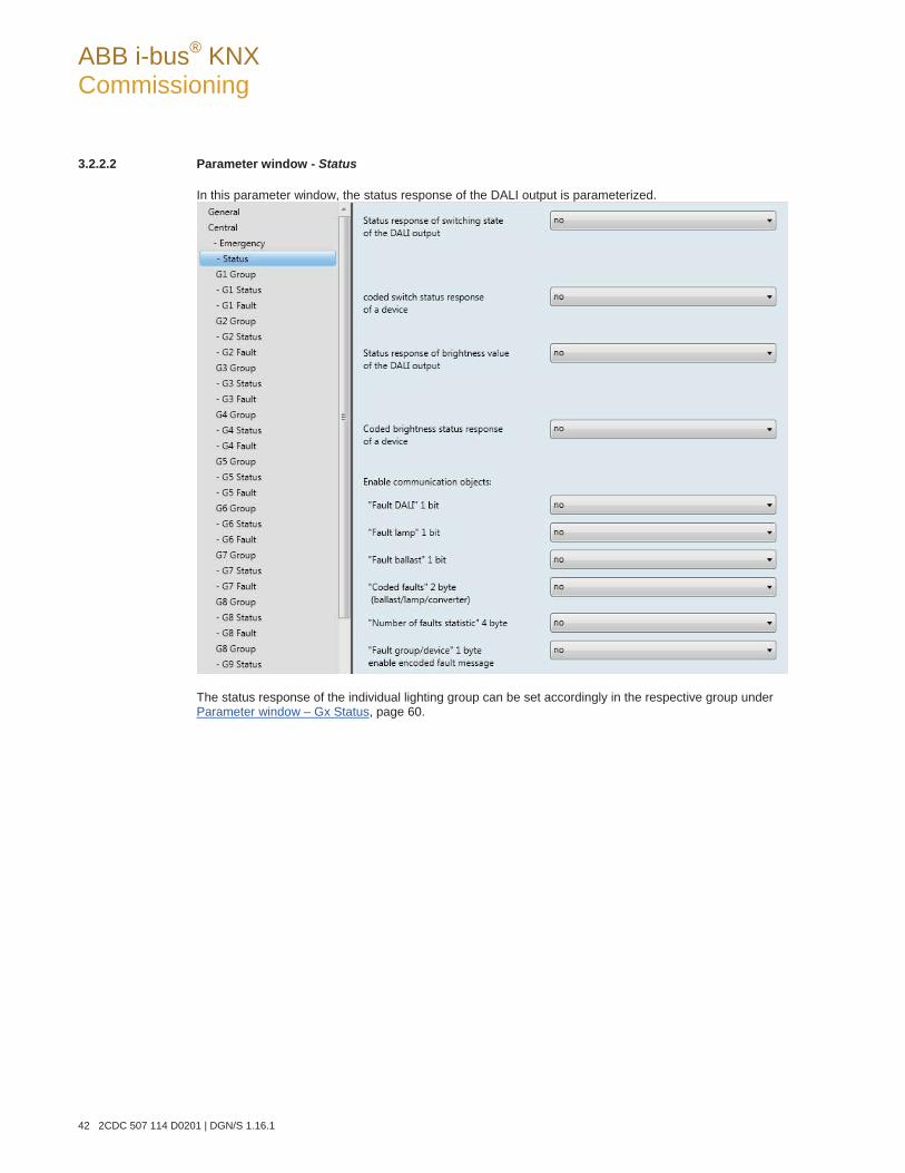
ABB i-bus® KNX Commissioning
42 2CDC 507 114 D0201 | DGN/S 1.16.1
3.2.2.2 Parameter window - Status
In this parameter window, the status response of the DALI output is parameterized.
The status response of the individual lighting group can be set accordingly in the respective group under Parameter window – Gx Status, page 60.
ABB i-bus® KNX Commissioning
DGN/S 1.16.1 | 2CDC 507 114 D0201 43
Status response of switching state of the DALI output Options: no yes: via object “Switch/status”
yes: via separate object "Status switch"
no: The status of the switch state is not actively sent on the KNX.
yes: via object “Switch/status”: The common communication object Switch/status (no. 10) receives the switch telegram, and the current status becomes active and is sent on the KNX.
yes: via separate object "Status switch": An additional communication object Status switch (no. 11) is enabled. Using it a 1 bit telegram with the actual switch status is sent on the KNX.
Note
This status message relates to all lighting groups of the DALI output. With a change of the parameterization or after a subsequent switching of the status object, the assign-ment of the group addresses already allocated to the Switch communication object is lost and needs to be reprogrammed. If the communication object Switch/status is used for switching and status feedback, particular care must be taken with the send properties of the communication objects. For further information see: Common communication object for control telegram and status, page 103
With the option yes:… two further parameters appear:
send object value Options: after a change
after request after a change or request
after a change: The status is sent after a change.
after request: The status is sent after a request.
after a change or request: The status is sent after a change or a request.
ABB i-bus® KNX Commissioning
44 2CDC 507 114 D0201 | DGN/S 1.16.1
Switch value for different values in the output Options: OFF
ON
This parameter defines the status to be sent if DALI devices with different states are present on the output.
OFF: The switch status is only sent as an ON (telegram with the value 1) if all DALI devices are switched on.
ON: The switch status is sent as an ON (telegram with the value 1) if at least one DALI device is switched on.
coded switch status response of a device Options: yes
no
no: The status of the switch status of a DALI device is not actively sent on the KNX.
yes: The coded communication object Status switch coded (no. 15) is enabled. Using this coded 2 byte communication object (address plus status), the switching state of an individual DALI device is sent on the KNX.
For further information see: Communication object no. 15, page 105.
With the option yes, a further parameter appears:
send object value Options: after a change
after request after a change or request
after a change: The status is sent after a change.
after request: The status is sent after a request.
after a change or request: The status is sent after a change or a request.
ABB i-bus® KNX Commissioning
DGN/S 1.16.1 | 2CDC 507 114 D0201 45
Status response of brightness value of the DALI output Options: no
yes: via object "Brightness value/status" yes: via separate obj. "Status brightness value"
The parameter defines how the current status of the brightness value of the DALI output (the lighting) is sent on the KNX.
no: The brightness value is not actively sent on the KNX.
yes: via object "Brightness value/status": The brightness value is sent on the KNX via the communica-tion object Brightness value/status (no. 13).
yes: via separate obj. "Status brightness value": An additional Status brightness value (no. 14) com-munication object for the status message is enabled.
Note
This status message relates to all connected devices of the DALI output. It is possible to parameterize the response of the status messages should differing states occur with the devices. With a change of the parameterization or after a subsequent switching of the status object, the assign-ment of the group's addresses already allocated to the communication object Brightness value are lost and need to be reprogrammed.
With the options yes:… two further parameters appear:
Send object value Options: after a change
after request after a change or request
after a change: The status is sent after a change.
after request: The status is sent after a request.
after a change or request: The status is sent after a change or a request.
Brightness value for different values in the output Options: average brightness of all lamps in the output
highest brightness of all lamps in the output lowest brightness of all lamps on the output
This parameter defines the status to be sent if devices with different states are present on the out-put.
average brightness of all lamps in the output: The average brightness of all DALI lighting groups is sent as the status of the DALI output on the KNX.
highest brightness of all lamps in the output: The highest brightness value of the DALI devices is taken as the status of the DALI output sent on the KNX.
lowest brightness of all lamps on the output: The lowest brightness value of the DALI devices is taken as the status of the DALI output sent on the KNX.
Using the following parameters, further communication objects and their associated functions for the output of the DGN/S can be enabled.
ABB i-bus® KNX Commissioning
46 2CDC 507 114 D0201 | DGN/S 1.16.1
Coded brightness status response of a device Options: yes
no
no: The status of the brightness status of a DALI device is not actively sent on the KNX.
yes: The coded communication object Status brightness value coded (no. 16) is enabled. Using this coded 2 byte communication object (address plus status), the brightness value of an individual DALI device is sent on the KNX.
For further information see: Communication object no. 16, page 106.
With the option yes, a further parameter appears:
send object value Options: after a change
after request after a change or request
after a change: The status is sent after a change.
after request: The status is sent after a request.
after a change or request: The status is sent after a change or a request.
Enable communication objects:
"Fault DALI" 1 bit Options: yes
no
Using this communication object, a fault of the DALI communication of the DALI output, i.e. a short-circuit > 500 ms or a data collision, can be sent or read, e.g. for diagnostic purposes. Some fault communication objects are available for a lamp/ballast fault.
no: The communication object Fault DALI is not enabled.
yes: The communication object Fault DALI is enabled. As soon as there is a DALI fault on the output, it is indicated by a 1 in the communication object Fault ballast. A further parameter ap-pears:
send object value Options: after a change
after request after a change or request
after a change: The status is sent after a change.
after request: The status is sent after a request.
after a change or request: The status is sent after a change or a request.
ABB i-bus® KNX Commissioning
DGN/S 1.16.1 | 2CDC 507 114 D0201 47
"Fault lamp" 1 bit Options: yes
no
Via this communication object, a fault of a lamp for the DALI output can be sent or read.
no: The communication object Fault lamp is not enabled.
yes: The communication object Fault lamp is enabled. As soon as there is a lamp fault on the output, it is indicated by a 1 in the communication object Fault lamp. A further parameter ap-pears:
Number of detected failures is greater or equal Options: 1…64
If the number of lamp faults reaches the value set here, the communication object Fault lamp is set to 1. If the number of lamp faults is less than the value set here, the communica-tion object Fault lamp contains the value 0.
send object value Options: after a change
after request after a change or request
after a change: The status is sent after a change.
after request: The status is sent after a request.
after a change or request: The status is sent after a change or a request.
ABB i-bus® KNX Commissioning
48 2CDC 507 114 D0201 | DGN/S 1.16.1
"Fault ballast" 1 bit Options: yes
no
Using this communication object, a ballast fault can be sent or read.
no: The communication object Fault ballast is not enabled.
yes: The communication object Fault ballast is enabled. As soon as there is a ballast fault on the output, it is indicated by a 1 in the communication object Fault ballast.
Note
In order to correctly detect the fault of a ballast, the DGN/S must have correctly identified all connected DALI devices and thus know the addresses to be monitored. This identification process can be triggered via the communication object Detect ballasts or with a long actuation of the button. An automatic detection e.g. after a KNX voltage recovery or Gateway operating voltage recovery does not take place. After approx. 90 seconds, all the DALI devices are de-tected, and the failure of a ballast can be correctly established. The activation should be carried out directly after commissioning or when extending or reducing the DALI devices. The DALI devices are continually monitored, regardless of whether the lamp is active or not active. The DALI devices must be installed properly and supplied with operating voltage. If all DALI devices of a lighting group are no longer recognised by the DGN/S, e.g. all ballasts have failed, the status values of the lighting group are reset as follows: Brightness value to 0, Switch state to 0 (OFF) and any existing lamp fault is reset, as a statement of the state of the lighting group is no longer possible.
With the option yes, two further parameters appear:
Number of detected failures must is greater or equal Options: 1… 64
If the number of ballast faults reaches the value set here, the communication object Fault ballast is set to 1. If the number of ballast faults is less than the value set here, the commu-nication object Fault ballast contains the value 0.
Send object value Options: after a change
after request after a change or request
after a change: The status is sent after a change.
after request: The status is sent after a request.
after a change or request: The status is sent after a change or a request.
ABB i-bus® KNX Commissioning
DGN/S 1.16.1 | 2CDC 507 114 D0201 49
"Coded faults" 2 byte (ballast/lamp/converter) Options: yes
no
Using this communication object (no. 20), the status of a fault for a lighting group or a DALI device is sent or read in the coded 2 byte communication object Status fault coded.
yes: The communication object Status fault coded is enabled. As soon as a ballast, lamp or emergency lighting converter fault has occurred in the set group or DALI device, this is indi-cated in the corresponding bit by the value 1.
no: The communication object Status fault coded is not enabled. For further information see: Communication object no. 20, page 108.
With the option yes, two further parameters appear:
send object value Options: after a change
after request after a change or request
after a change: The status is sent after a change.
after request: The status is sent after a request.
after a change or request: The status is sent after a change or a request.
"Number of faults statistic" 4 byte Options: yes
no
Using this coded 4 byte communication object (no. 21), the number of ballasts, lamps and emer-gency lighting converters can be sent or read.
yes: The coded 4 byte communication object Number of faults statistic (no. 21) is enabled. As soon as the number of faults on the output changes, this is indicated via this coded communi-cation object Number of faults statistic (no. 21).
no: The communication object Number of faults statistic is not enabled.
With the option yes, two further parameters appear:
send object value Options: after a change
after request after a change or request
after a change: The status is sent after a change.
after request: The status is sent after a request.
after a change or request: The status is sent after a change or a request.
ABB i-bus® KNX Commissioning
50 2CDC 507 114 D0201 | DGN/S 1.16.1
"Fault group/device" 1 byte enable encoded fault message Options: yes
no
This parameter enables the communication object Fault group/device. The fault status (lamp, bal-last fault and emergency lighting converter) of the lighting groups or the individual DALI devices are sent on the KNX. Furthermore, the communication objects Number of faults (no. 22) and Switch up next fault alarm (no. 24) are enabled. For further information see: Communiation object no. 22 to 24, page 110 and Code table Fault group/device(no. 20), page 151
no: The communication object Fault group/device (no. 23) with the partner communication ob-jects no. 22 and no. 24 is not enabled.
yes: The communication object Fault group/device (no. 23) with the partner communication ob-jects (no. 22 and no. 24) is enabled. A further parameter appears:
Code correspond to group or device Options: based on DALI device
group orientated
This parameter determines whether the coded fault relates to a lighting group or an individ-ual DALI device.
based on DALI device: The value of the communication object Fault group/device re-lates to the fault on a DALI device.
group orientated: The value of the communication object Fault group/device relates to the fault on a lighting group.
ABB i-bus® KNX Commissioning
DGN/S 1.16.1 | 2CDC 507 114 D0201 51
3.2.2.3 Parameter window Gx Group
In these parameter window, the properties for every lighting group are parameterized.
First of all, the lighting group to be parameterizd is selected by the number of the lighting group G1…G16. The lighting groups are parameterized independently of each other. For this reason, we refer to the gen-eral lighting group Gx in the following. X can represent any of the 16 lighting groups.
The assignment of the individual DALI lamps to a lighting group is undertaken with the ETS independent DALI-Software-Tool. For further information see: DALI-Software-Tool, page Fehler! Textmarke nicht definiert.
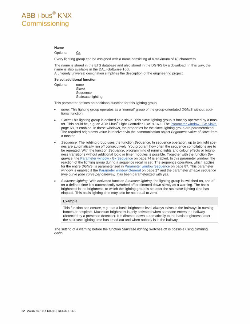
ABB i-bus® KNX Commissioning
52 2CDC 507 114 D0201 | DGN/S 1.16.1
Name Options: Gx
Every lighting group can be assigned with a name consisting of a maximum of 40 characters.
The name is stored in the ETS database and also stored in the DGN/S by a download. In this way, the name is also available in the DALI-Software-Tool. A uniquely universal designation simplifies the description of the engineering project.
Select additional function Options: none
Slave Sequence Staircase lighting
This parameter defines an additional function for this lighting group.
none: This lighting group operates as a “normal” group of the group-orientated DGN/S without addi-tional function.
Slave: This lighting group is defined as a slave. This slave lighting group is forcibly operated by a mas-ter. This could be, e.g. an ABB i-bus® Light Controller LR/S x.16.1. The Parameter window - Gx Slave, page 68, is enabled. In these windows, the properties for the slave lighting group are parameterized. The required brightness value is received via the communication object Brightness value of slave from a master.
Sequence: The lighting group uses the function Sequence. In sequence operation, up to ten light sce-nes are automatically run off consecutively. You program how often the sequence compilations are to be repeated. With the function Sequence, programming of running lights and colour effects or bright-ness transitions without additional logic or timer modules is possible. Together with the function Se-quence, the Parameter window - Gx Sequence on page 74 is enabled. In this parameter window, the reaction of the lighting group during a sequence recall is set. The sequence operation, which applies for the entire DGN/S, is parameterized in Parameter window Sequence on page 87. This parameter window is enabled if the Parameter window General on page 27 and the parameter Enable sequence time curve (one curve per gateway), has been parameterized with yes.
Staircase lighting: With activated function Staircase lighting, the lighting group is switched on, and af-ter a defined time it is automatically switched off or dimmed down slowly as a warning. The basis brightness is the brightness, to which the lighting group is set after the staircase lighting time has elapsed. This basis lighting time may also be not equal to zero.
Example
This function can ensure, e.g. that a basis brightness level always exists in the hallways in nursing homes or hospitals. Maximum brightness is only activated when someone enters the hallway (detected by a presence detector). It is dimmed down automatically to the basis brightness, after the staircase lighting time has timed out and when nobody is in the hallway.
The setting of a warning before the function Staircase lighting switches off is possible using dimming down.
ABB i-bus® KNX Commissioning
DGN/S 1.16.1 | 2CDC 507 114 D0201 53
Note
These three additional functions, Slave, Sequence and Staircase light can assume three operating states: Additional function is not active: The additional function has been deactivated via its communication object Select additional function; a telegram with value 0 has been received. In this state, the DGN/S behaves like a “normal” group-orientated DGN/S. In this state, an ON telegram does not start the additional function. Only after a telegram with the value 1 has been received on the communication object Select additional function is it possible to start the additional function. Additional function is in standby mode: The additional function is active but has however been interrupted, e.g. by the OFF telegram. The lighting group is in standby mode. With an ON telegram (telegram to the communication object Switch), the additional function is again triggered, i.e., the Se-quence or the Staircase lighting runs, the slave lighting group again responds to the communication object Brightness value of slave. Additional function runs: The Sequence or the Staircase light runs, the function Slave receives brightness values from the master. With corresponding parameterization of the switching telegrams, the additional functions can be set to standby mode. State after download: After a download, the additional functions are active and can be found in stand-by mode. Thus, the additional function can be started immediately after download without any additional activation, exclusively with a corresponding ON telegram. When the corresponding communication object for the status message of the additional function is enabled via the parameterization, the status of the additional function (activated/deactivated) is sent via the respective communication object Activate additional function/status after a download.
If an additional function is selected, the following parameters apply for the time period in which the addi-tional function is inactive.
Brightness value when turned ON Options: last value
100 % (255) … 1 % (3)
The parameter name changes if an additional function is selected: Brightness value when turned ON (only if additional function is not activated).
This parameter defines the brightness value, which is used to switch on the lighting group when an ON te-legram is received.
If a value is set, which is outside the dimming value range (Maximum brightness value or Minimal bright-ness value), the threshold is set as the minimum or maximum brightness value.
If for example, the lighting group is at a brightness value, which is not equal to the switch on value, and it receives an ON telegram, the parameterized switch on value is set.
last value: The lighting group switches on with the brightness value, which it had when the OFF tele-gram was received.
ABB i-bus® KNX Commissioning
54 2CDC 507 114 D0201 | DGN/S 1.16.1
Note
Saving the last brightness value is undertaken with every OFF telegram except for the lighting groups already switched off. In this case, with a further OFF telegram, the OFF state is not saved as the last brightness value. If a renewed switch OFF telegram is received during dimming down, the current brightness value is saved as the last brightness value. If the gateway operating voltage fails, the last brightness value is lost, and after recovery of the gateway operating voltage maximum brightness is set. The last brightness value is retained after a download or KNX voltage failure. A differentiation is made between the last brightness value with central switching via the communication object Switch (DALI output) and group-orientated switching via communication object Switch (Group x). Both values are independent of each other. This means if some lighting groups are dimmed or switched on or off via a central telegram, the last brightness values for the lighting group are retained without change. When an ON telegram is received for the lighting group, the brightness value, which was set with the last OFF telegram, is set again with the lighting group.
Minimum brightness value Options: 100 % (255)
… 1 % (3)
This parameter defines the minimum brightness value, which the lamps of the lighting group assume. This value is stored in the DALI devices and thus applies for all functions. If a minimum brightness value is set, which exceeds the maximum brightness value, the minimum brightness value is set equal to the maximum brightness value.
If the function Burn in lamps is activated, the lamp group will be operated only with 0 % (OFF) or 100 % brightness, regardless of this setting.
If a brightness value is received via the communication objects Brightness value and Brightness va-lue/status or Brightness value of slave, which are below the defined minimum dimming value, the minimum dimming value is set.
The Minimal brightness value also applies in the functions Staircase light, Scene and Sequence.
Important
The maximum and minimum dimming values selected for the lighting group are also valid with a central telegram via the communication objects of the DALI output. Example: Lighting group 1 is parameterized with a minimum dimming value of 20 %; lighting group 2 is parameterized with 10 %. If the DGN/S receives a central telegram in this constellation: set the bright-ness value to 5 %; lighting group 1 is set to 20 %, and lighting group 2 is set to 10 %.
ABB i-bus® KNX Commissioning
DGN/S 1.16.1 | 2CDC 507 114 D0201 55
Maximum brightness value Options: 100 % (255)
… 1 % (3)
This parameter defines the maximum brightness value, which the lamps of the lighting group can assume. This value is stored in the DALI devices and thus applies for all functions. If a maximum brightness value is set, which is below the minimum dimming value, the maximum brightness value is set equal to the mini-mum brightness value.
If the function Burn-in lamps is activated, the lamp group will be operated only with 0 % (OFF) or 100 % brightness, regardless of this setting.
If a brightness value is received via the communication objects Brightness value, Brightness value/status or Brightness value of slave, which is above the defined maximum dimming value, the maximum dimming value is set.
The maximum brightness value also applies in the functions Staircase light, Scene and Sequence.
Note
The maximum and minimum dimming values selected for the lighting group are also valid with a central telegram via the communication objects of the DALI output. Example: Lighting group 1 is parameterized with a maximum dimming value of 80 %; lighting group 2 is parameterized with 90 %. If the DGN/S receives a central telegram in this constellation to set the brightness value to 100 %; lighting group 1 is set to 80 %, and lighting group 2 is set to 90 %.
Allow switching ON via dim telegram Options: yes
no
This parameter defines the switch on response of the lighting group at dimming.
yes: Switch ON using the dim telegram is allowed.
no: Switch ON using the DIM telegram is not allowed. The lighting group must be switched on in order to be dimmed.
Allow switching OFF via dim telegram Options: yes
no
This parameter defines the switch off response of the lighting group at dimming.
yes: Switch OFF via a DIM telegram is allowed.
no: Switch OFF via a DIM telegram is not allowed. The lighting group must be switched off explicitly via an OFF telegram. Independent dimming down is not possible.
ABB i-bus® KNX Commissioning
56 2CDC 507 114 D0201 | DGN/S 1.16.1
Allow switching ON via brightness value Options: yes
no
This parameter defines the switch on performance of the lighting group with a received brightness value.
yes: Switch on with a brightness value is permitted.
no: Switch on with a brightness value is not permitted. The lighting group must be switched on in order to execute the brightness value telegram.
Allow switching OFF via brightness value Options: yes
no
This parameter defines the switch off performance with a received brightness value.
yes: Switch off with a brightness value is permitted.
no: Switch off with a brightness value is not permitted. The DALI output must be implemented with an OFF telegram via the communication objects Switch or Switch/status.
Dim period to reach turn on or off brightness (Fct. "Switch") in s Options: 0…2…65,535
A soft start or soft stop can be set with this parameter. For this purpose, the time duration in which the DGN/S dims the lighting group from 0 % brightness to the switch on value with an ON telegram is defined. The same speed also applies for an OFF telegram. The dim period is only relevant for ON/OFF telegrams (1 Bit).
Dimming time changeable via obj. "Flexible time" 2 Byte Options: yes
no
The time received via the communication object Flexible time has an effect on the ON/OFF switch-ing performance. The flexible dimming time has a value between 0…65,535 seconds. For further information see communication object no. 27, page 112..
yes: The time received via the central communication object Flexible time (DALI output) is used as a dimming time for the switch on/off value.
no: The dimming time for the switching on and off value cannot be changed via KNX.
Note
The switch off time is also considered when the lighting group is at the lower dimming threshold and an OFF telegram is received. In this case, the lighting group switches off at the lower dim-ming value limit only after the programmed dimming time for switch ON/OFF. This ensures that all lighting groups switch off simultaneously.
ABB i-bus® KNX Commissioning
DGN/S 1.16.1 | 2CDC 507 114 D0201 57
Dim period to reach set brightness value ("Brightness value") in s [0...65,535] Options: 0…2…65,535
This parameter determines the time duration, in which the DGN/S sets the received brightness value for the lighting group via communication objects Brightness value or Brightness value/status.
Dimming time changeable via obj. "Flexible time" 2 Byte Options: yes
no
The time received via the communication object Flexible time has an effect on the communication object Set brightness value. The flexible dimming time has a value between 0…65,535 seconds. For further information see communication object no. 27, page 112.
yes: The time received via the central communication object Flexible time (DALI output) is used as a dimming time until the brightness value is achieved.
no: The dimming time until the brightness value is achieved cannot be changed via the KNX.
Dimming speed, time for 0...100 % (Function „Relative dimming“) in s [65,535] Options: 0…5…65535
This parameter defines the period, in which a dimming process occurs, from 0...100 %. This dimming time only affects dimming actions, which were initiated by the communication object Relative dimming.
Dimming time changeable via obj. "Flexible time" 2 Byte Options: yes
no
The time received via the communication object Flexible time has an effect on the dimming speed with relative dimming. The flexible dimming time has a value between 0…65,535 seconds. For further information see communication object no. 27, page 112.
yes: The time received via the central communication object (DALI output) Flexible time is used as a dimming time for Relative dimming.
no: The dimming time for Relative dimming cannot be changed via the KNX.
ABB i-bus® KNX Commissioning
58 2CDC 507 114 D0201 | DGN/S 1.16.1
Characteristic adjustment of DALI lighting curve Options: no, logarithm DALI lighting curve
linear dimming curve linear dimming curve, without phys-min brightness value
With this parameter, it is possible to adapt the dimming curve for the control of a lighting group.
The method of adaptation of the value range for the brightness values of the KNX (0, 1…255 or 0…100 %) to DALI (0, 1…254 or 0, physical minimum …254) can be parameterized. For further information see: DALI lighting curve, page 147
Note
The physical minimum is the minimum brightness value that the ballast can set based on its physical properties. The term originates directly from the IEC 62386 and EN 60929.
no, logarithm DALI lighting curve: The dimming curve is not modified. The DALI dimming curve as it is
stipulated in the DALI standard (EN 62386 and EN 60929) is used unchanged for the control of DALI devices.
For further information see: DALI lighting curve, page 147
linear dimming curve: The KNX value range is converted to the DALI value range, so that a linear rela-tionship between KNX values and DALI values (electronic power on the lighting equipment or lumi-nous flux) results. The logarithmic DALI curve is thus converted to a linear representation.
In this way, ballasts with an applied minimum dimming value (in other words luminous flux) of 3 % can be controlled exactly with this value. Should the logarithmic DALI curve be applied, the KNX value of 50 % would be applied in this case.
For further information see: DALI lighting curve, page 147
linear dimming curve, without phys-min brightness value: The KNX value range (1…255) is converted to the DALI value range (physical minimum…254), whereby the unusable range of DALI control val-ues (0…physical minimum), which the lighting equipment cannot realise, is omitted.
For further information see: DALI lighting curve, page 147
ABB i-bus® KNX Commissioning
DGN/S 1.16.1 | 2CDC 507 114 D0201 59
Enable with function Burn-in (Object "Burn-in lamps/status") Options: yes
no
This parameter defines whether the lighting group should be considered with function Burn-in. Lighting equipment, e.g. incandescent bulbs, which does not require a burn-in phase can be excluded from the burn-in process. They can always be dimmed independently of the function Burn-in.
The function Burn-in applies for all lighting groups even with the corresponding burn-in time and is enabled in Parameter window Central, page 32.
yes: The lighting group is considered during active function Burn-in and during the burn-in phase and it can only be switched off with 0 % brightness (OFF) and on with 100 % brightness (ON).
no: The lighting group is not taken into consideration during an activated function Burn-in and can also be dimmed during an activated function burn-in.
Enable with slave emergency (Object "Slave emergency active/status") Options: yes
no
This parameter defines whether the lighting group should be considered when function Slave emergency is activated. Hereby the functional lamps can be put into the emergency lighting state. The response of the functional lamps during slave emergency lighting operation can be parameterized in Parameter window -Emergency, page 39.
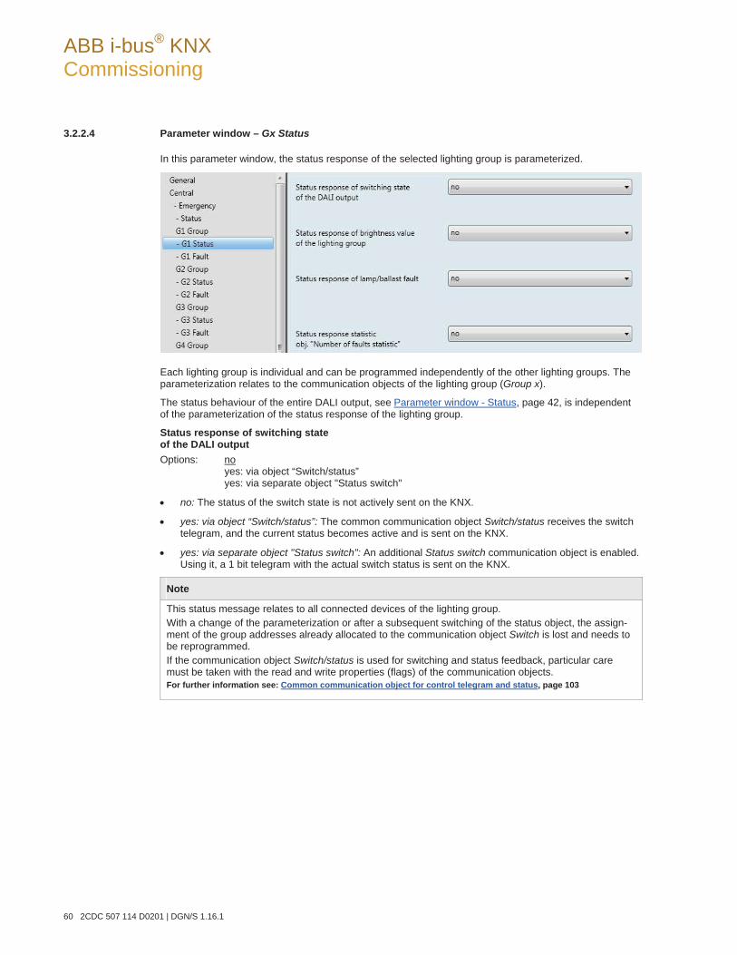
ABB i-bus® KNX Commissioning
60 2CDC 507 114 D0201 | DGN/S 1.16.1
3.2.2.4 Parameter window – Gx Status
In this parameter window, the status response of the selected lighting group is parameterized.
Each lighting group is individual and can be programmed independently of the other lighting groups. The parameterization relates to the communication objects of the lighting group (Group x).
The status behaviour of the entire DALI output, see Parameter window - Status, page 42, is independent of the parameterization of the status response of the lighting group.
Status response of switching state of the DALI output Options: no yes: via object “Switch/status”
yes: via separate object "Status switch"
no: The status of the switch state is not actively sent on the KNX.
yes: via object “Switch/status”: The common communication object Switch/status receives the switch telegram, and the current status becomes active and is sent on the KNX.
yes: via separate object "Status switch": An additional Status switch communication object is enabled. Using it, a 1 bit telegram with the actual switch status is sent on the KNX.
Note
This status message relates to all connected devices of the lighting group. With a change of the parameterization or after a subsequent switching of the status object, the assign-ment of the group addresses already allocated to the communication object Switch is lost and needs to be reprogrammed. If the communication object Switch/status is used for switching and status feedback, particular care must be taken with the read and write properties (flags) of the communication objects. For further information see: Common communication object for control telegram and status, page 103
ABB i-bus® KNX Commissioning
DGN/S 1.16.1 | 2CDC 507 114 D0201 61
With the option yes…two further parameters appear:
send object value Options: after a change
after request after a change or request
after a change: The status is sent after a change.
after request: The status is sent after a request.
after a change or request: The status is sent after a change or a request.
Status response of brightness value of the lighting group Options: no
yes: via object "Brightness value/status" yes: via separate obj. "Status brightness value"
The parameter defines how the current status of the brightness value of the DALI output (the lighting) is sent on the KNX.
no: The brightness value is not actively sent on the KNX.
yes: via object "Brightness value/status": The brightness value is sent on the KNX via the communica-tion object Brightness value/status.
yes: via separate obj. "Status brightness value": An additional communication object Status brightness value for the status message is enabled.
With the option yes…, a further parameter appears:
send object value Options: after a change
after request after a change or request
after a change: The status is sent after a change.
after request: The status is sent after a request.
after a change or request: The status is sent after a change or a request.
ABB i-bus® KNX Commissioning
62 2CDC 507 114 D0201 | DGN/S 1.16.1
Status response of lamp/ballast fault Options: yes
no
This parameter defines how the current status of a lamp/ballast fault is sent. The communication object Fault lamp or ballast is enabled.
yes: A status message is sent.
no: No status message is sent.
With the option yes, two further parameters appear:
send object value Options: after a change
after request after a change or request
after a change: The status is sent after a change.
after request: The status is sent after a request.
after a change or request: The status is sent after a change or a request.
Content of communication object Options: Fault lamp
Fault ballast Fault lamp or ballast
This parameter determines the equipment fault, which is provided on the enabled communication object.
Fault lamp: The communication object Fault lamp is enabled. Using this communication object, it is possible to provide information on whether the lighting group of a lamp has failed on the KNX. Should there be a fault, the communication object Fault lamp is written with a 1 and sent on the KNX in dependence on the parameterization set beforehand.
Fault ballast: The communication object Fault ballast is enabled. Using this communication ob-ject, it is possible to provide information on whether the lighting group of a ballast has failed on the KNX. Should there be a fault, the communication object Fault lamp is written with a 1 and sent on the KNX in dependence on the parameterization set beforehand.
Fault lamp or ballast The communication object Fault lamp or ballast is enabled. Using this communication object, it is possible to provide information on the KNX relating to a lamp failure or a ballast failure in the lighting group.
Note
In order to correctly detect a ballast fault, the function Detect ballasts must however be activated in the DGN/S. Using this function, the DGN/S notes the exact quantity of DALI devices currently connected to the DGN/S as a reference value. Should the detected number of DALI devices diverge from the current reference value, this will be evaluated as a ballast fault and displayed via the communication object, in dependence on the set send parameterization on the KNX. The function Detect ballasts can be triggered either via the communication object Detect bal-lasts, by a long button push on the button or by using the separate DALI-Software-Tool.
ABB i-bus® KNX Commissioning
DGN/S 1.16.1 | 2CDC 507 114 D0201 63
Status response statistic obj. "Number of faults statistic" Options: yes
no
This parameter enables the 4 byte communication object Number of faults statistic. Using this communica-tion object, the number of different faults (lamp, emergency lighting converter, ballast) or the sum of all faults in the lighting group is queried or sent via a single communication object.
yes: Using the communication object Number of faults statistic, the number of different faults (lamp, emergency lighting converter, ballast) or the sum of all faults in the lighting group are queried or sent via a single communication object.
no: The information about the number of faults in a lighting groups is not sent in a single communica-tion object on the KNX.
With the option yes…, a further parameter appears:
send object value Options: after a change
after request after a change or request
after a change: The status is sent after a change.
after request: The status is sent after a request.
after a change or request: The status is sent after a change or a request.
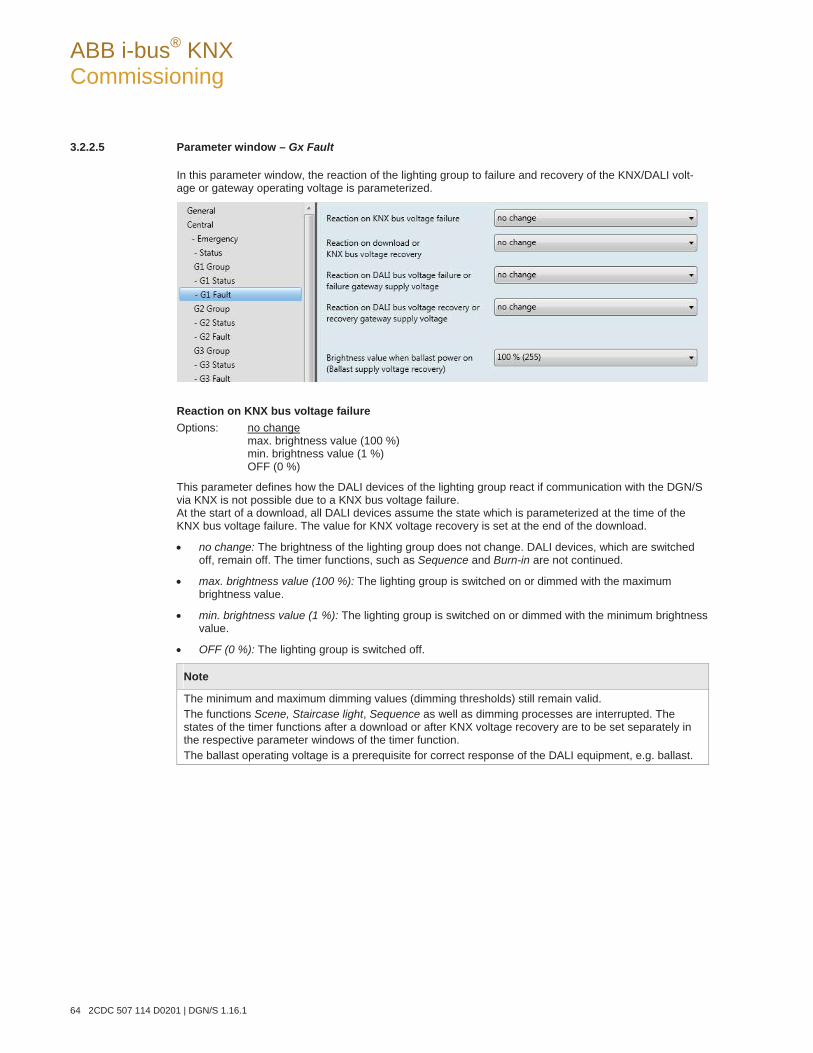
ABB i-bus® KNX Commissioning
64 2CDC 507 114 D0201 | DGN/S 1.16.1
3.2.2.5 Parameter window – Gx Fault
In this parameter window, the reaction of the lighting group to failure and recovery of the KNX/DALI volt-age or gateway operating voltage is parameterized.
Reaction on KNX bus voltage failure Options: no change
max. brightness value (100 %) min. brightness value (1 %) OFF (0 %)
This parameter defines how the DALI devices of the lighting group react if communication with the DGN/S via KNX is not possible due to a KNX bus voltage failure. At the start of a download, all DALI devices assume the state which is parameterized at the time of the KNX bus voltage failure. The value for KNX voltage recovery is set at the end of the download.
no change: The brightness of the lighting group does not change. DALI devices, which are switched off, remain off. The timer functions, such as Sequence and Burn-in are not continued.
max. brightness value (100 %): The lighting group is switched on or dimmed with the maximum brightness value.
min. brightness value (1 %): The lighting group is switched on or dimmed with the minimum brightness value.
OFF (0 %): The lighting group is switched off.
Note
The minimum and maximum dimming values (dimming thresholds) still remain valid. The functions Scene, Staircase light, Sequence as well as dimming processes are interrupted. The states of the timer functions after a download or after KNX voltage recovery are to be set separately in the respective parameter windows of the timer function. The ballast operating voltage is a prerequisite for correct response of the DALI equipment, e.g. ballast.
ABB i-bus® KNX Commissioning
DGN/S 1.16.1 | 2CDC 507 114 D0201 65
Reaction on download or KNX bus voltage recovery Options: no change
Status before failure max. brightness value (100 %) min. brightness value (1 %) OFF (0 %)
This parameter determines how the DALI device of the lighting group reacts after a download or at KNX bus voltage recovery.
no change: The brightness of the lighting group does not change. DALI devices, which are switched off, remain off.
Status before failure: The lighting group is brought to the state which it had before the download or KNX bus voltage failure. The brightness value must be set for at least two seconds before KNX volt-age failure or a download in order to ensure that it is set again after KNX bus voltage recovery.
max. brightness value (100 %): The lighting group is switched on or dimmed with the maximum brightness value.
min. brightness value (1 %): The lighting group is switched on or dimmed with the minimum brightness value.
OFF (0 %): The lighting group is switched off.
Note
The minimum and maximum dimming values (dimming thresholds) still remain valid. The functions Scene, Staircase light, Sequence as well as dimming processes are interrupted. The states of the timer functions after a download or after KNX voltage recovery are to be set separately in the respective parameter windows of the additional function. The ballast operating voltage is a prerequisite for correct response of the DALI equipment, e.g. ballast.
Reaction on DALI bus voltage failure or failure gateway supply voltage Options: no change
max. brightness value (100 %) min. brightness value (1 %) OFF (0 %)
This parameter defines how the DALI devices of the lighting group react if communication with the DALI devices via KNX is not possible due to a DALI bus voltage failure or Gateway supply voltage failure.
ABB i-bus® KNX Commissioning
66 2CDC 507 114 D0201 | DGN/S 1.16.1
A DALI voltage failure occurs with a cable break on the DALI control line, a short circuit of the line or a fail-ure of the gateway operating voltage.
no change: The brightness of the lighting group does not change. DALI devices, which are switched off, remain off. As the information no change is stored in the ballast, all DALI devices react immedi-ately after the bus voltage failure.
max. brightness value (100 %): The lighting group is switched on or dimmed with the maximum brightness value.
min. brightness value (1 %): The lighting group is switched on or dimmed with the minimum brightness value.
OFF (0 %): The lighting group is switched off.
Note
The minimum and maximum dimming values (dimming thresholds) still remain valid. The functions Scene, Staircase light, Sequence as well as dimming processes are interrupted. The states of the timer functions after a download or after KNX voltage recovery are to be set separately in the respective parameter windows of the additional function. The ballast operating voltage is a prerequisite for correct response of the DALI equipment, e.g. ballast.
Reaction of DALI bus voltage recovery or recovery gateway supply voltage Options: no change
status before failure max. brightness value (100 %) min. brightness value (1 %) OFF (0 %)
This parameter defines how the DALI devices of the lighting group react at DALI bus voltage recovery or gateway supply voltage recovery.
no change: The brightness of the lighting group does not change. DALI devices, which are switched off, remain off.
Status before failure: The lighting group is brought to the state which it had before the DALI voltage failure or gateway operating voltage failure. The brightness value must be set for at least two seconds before DALI voltage failure or a gateway operating voltage failure, in order to ensure that it is set again after DALI bus voltage recovery or gateway operating voltage recovery.
Note
Please note that the current brightness value is written every two to ten seconds into scene 15 of the DALI device with this parameter setting. It is therefore essential to ensure that the connected DALI devices can store the scene values as often as necessary without being damaged. This may not be the case with some older DALI devices. Please contact the respective manufacturers for information.
ABB i-bus® KNX Commissioning
DGN/S 1.16.1 | 2CDC 507 114 D0201 67
max. brightness value (100 %): The lighting group is switched on or dimmed with the maximum brightness value.
min. brightness value (1 %): The lighting group is switched on or dimmed with the minimum brightness value.
OFF (0 %): The lighting group is switched off.
Note
The minimum and maximum dimming values (dimming thresholds) still remain valid. Scenes, staircase lighting, sequences as well as dimming processes are interrupted. The states of the timer functions after a DALI voltage recovery or after a gateway supply voltage recovery is to be set separately in the respective parameter windows of the additional function. The ballast operating voltage is a prerequisite for correct response of the DALI equipment, e.g. ballast.
Interaction between ballast power on and DALI voltage recovery The power-on level of the ballast is set first of all after ballast operating voltage recovery. This brightness value is stored in the ballast and is thus set immediately after the ballast operating volt-age recovery. Simultaneously, the DGN/S on the DALI will once again receive responses from the ballast. As a result, the DGN/S informs the re-detected ballast again about the lighting group infor-mation. After to this procedure, the lamps are controlled with the parameterizsed brightness level at DALI voltage recovery.
Brightness value when ballast power on (Ballast supply voltage recovery) Options: 100 % (255)
… 1 % (3) 0 % (OFF)
This parameter determines the response of the ballast at ballast operating voltage recovery. A storage lo-cation is provided in the ballast for this purpose. The brightness value used by the ballast at ballast operat-ing voltage recovery to switch on the lamp is stored at this memory location. The brightness value of the ballast is set as a factory default value to the maximum brightness (100 %). This has the advantage that without any DALI programming or commissioning requirement, the ballast equipment is switched on and off normally via the operating voltage of the ballast. This can be useful par-ticularly during commissioning. Should no DALI commissioning have been undertaken, the lighting can be switched on and off via the operating voltage of the ballast using a normal miniature circuit-breaker.
In “normal” operation, this reaction may not be desirable: At ballast operating voltage failure and ballast operating voltage recovery, all ballasts switch on with the maximum brightness. This can lead to increased inrush current and in the worst case can cause a circuit-breaker to trip. Moreover, the entire building is fully illuminated and must be switched off manually.
In order to allow the user to set the default factory switch on response with ballast operating voltage re-covery, the parameter can be used to set any brightness value between 0 % (OFF) and 100 % maximum brightness value.
100 % (255)…0 % (OFF): This is the brightness value used to switch on the ballast device after ballast operating voltage recovery.
Important
The factory default setting of the ballast is changed with this parameter.

ABB i-bus® KNX Commissioning
68 2CDC 507 114 D0201 | DGN/S 1.16.1
3.2.2.6 Parameter window – Gx Slave emergency
This parameter is enabled if in Parameter window Gx Group, page 51, the parameter Enable with function slave emergency (Object "Slave emergency active/status") has been parameterized with the option yes. In this parameter window, the reaction of a functional lighting group with a slave emergency lighting situation that is triggered by the communication object slave emergency active/status is defined. The prerequisite for this is that the lamps can be controlled during slave emergency lighting operation via the DGN/S, i.e. the are ready for operation via the DGN/S.
Brightness value of lighting group during slave emergency Options: 100 %(255)…1 %(1)
This parameter defines the brightness value of the lighting group in slave emergency lighting operation, that is triggered by the communication object Slave emergency mode active/status. It is a prerequisite that the lighting group can be controlled via the DGN/S.
Behaviour lighting group during slave emergency Options: OFF and blocked
OFF and not blocked unchanged and not blocked
This parameter determines how the lighting group responds during slave emergency lighting when the communication object Slave emergency active/status triggers slave emergency lighting operation. It is a prerequisite that the lighting can be controlled via the DGN/S.
…not blocked: The lighting group is switched on at the start of slave emergency lighting with the brightness value of the slave and is, however, not blocked. Switching telegrams via the KNX are trans-ferred and implemented.
…blocked: The lighting group is switched on at the start of slave emergency lighting with the bright-ness value of the slave and remains blocked, until the slave emergency lighting state has ended. Switching telegrams received via the KNX are not implemented. After the end of slave emergency lighting operation, the brightness value is set with the next parameter for the lighting group.
Important
If at least one of the 16 lighting groups is in slave emergency lighting and has been parameterized as blocked, not only are the KNX group commands of the lighting groups blocked, but also all KNX broad-cast commands for the DALI output.

ABB i-bus® KNX Commissioning
DGN/S 1.16.1 | 2CDC 507 114 D0201 69
Brightness value of lighting group after slave emergency Options: 0% (OFF), 1 % (3)…100 % (255)
This parameter defines the brightness of the lighting group after the slave emergency lighting state has ceased. The slave emergency lighting operation is ended when a telegram with the value 0 is received via the communication object Slave emergency active/status or internally if the slave emergency requirement is not longer fulfilled. The internally slave emergency requirement has a higher priority as the a telegram with value 0..
Important
The settings relate to the (Slave) emergency lighting operation that is triggered via the communication object Output Slave emergency active/status triggered. The communication object should be enabled in the Parameter window Central, page 32.
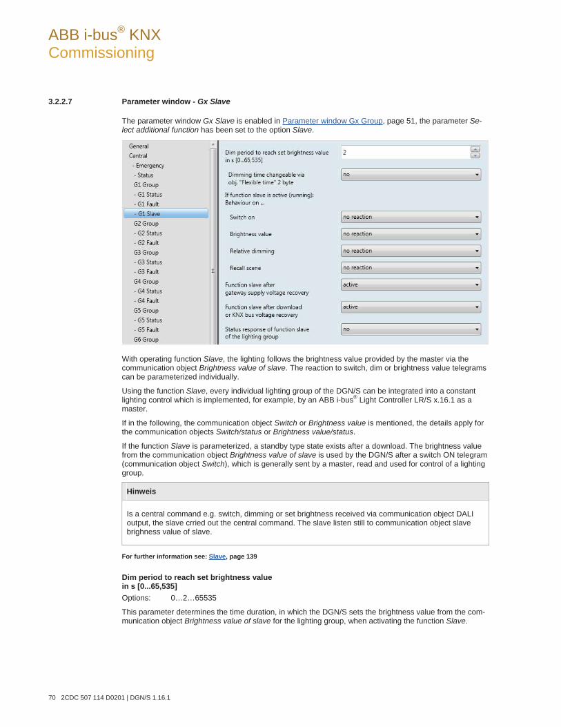
ABB i-bus® KNX Commissioning
70 2CDC 507 114 D0201 | DGN/S 1.16.1
3.2.2.7 Parameter window - Gx Slave
The parameter window Gx Slave is enabled in Parameter window Gx Group, page 51, the parameter Se-lect additional function has been set to the option Slave.
With operating function Slave, the lighting follows the brightness value provided by the master via the communication object Brightness value of slave. The reaction to switch, dim or brightness value telegrams can be parameterized individually.
Using the function Slave, every individual lighting group of the DGN/S can be integrated into a constant lighting control which is implemented, for example, by an ABB i-bus® Light Controller LR/S x.16.1 as a master.
If in the following, the communication object Switch or Brightness value is mentioned, the details apply for the communication objects Switch/status or Brightness value/status.
If the function Slave is parameterized, a standby type state exists after a download. The brightness value from the communication object Brightness value of slave is used by the DGN/S after a switch ON telegram (communication object Switch), which is generally sent by a master, read and used for control of a lighting group.
Hinweis Is a central command e.g. switch, dimming or set brightness received via communication object DALI output, the slave crried out the central command. The slave listen still to communication object slave brighness value of slave.
For further information see: Slave, page 139
Dim period to reach set brightness value in s [0...65,535] Options: 0…2…65535
This parameter determines the time duration, in which the DGN/S sets the brightness value from the com-munication object Brightness value of slave for the lighting group, when activating the function Slave.
ABB i-bus® KNX Commissioning
DGN/S 1.16.1 | 2CDC 507 114 D0201 71
Dimming time changeable via obj. "Flexible time" 2 byte Options: yes
no
The time received via the communication object Flexible time defines the duration until the bright-ness value received by the communication object Brightness value of slave, has been achieved. The flexible dimming time has a value between 0…65,535 seconds.
yes: The time received via the central communication object (DALI output) Flexible time is used as a dimming time for the switch on/off value.
no: The dimming time for the switching on and off value cannot be changed via KNX.
If function Slave is active (running): Behaviour on …
Switch on Options: no reaction
set function in standby
With activated function Slave, the parameter can be used to define the reaction to an ON telegram on the communication object Switch or Switch/status.
no reaction: An ON telegram is ignored.
set function in standby: An ON telegram ends function Slave, and the DGN/S carries out the switch telegram. The function Slave is latent and waits until a renewed activation (standby sta-te) via the communication object function Activate function Slave or via a telegram with the va-lue 1 to the communication object Switch or Switch/status.
Note
The reaction to an OFF telegram on the communication object Switch or Switch/status cannot be parameterized. An OFF command always interrupts the function Slave. The function Slave goes over to standby mode, in which the brightness values on the communication object Brightnessvalue of slave is ignored. The function Slave is reactivated, if an ON telegram is received on the communication object Switch or Switch/status or a telegram with the value 1 is received on communication object Activate function Slave. The master/slave unit is separated, for example, by deactivation of the function Slave (telegram with the value 0 to communication object Activate function Slave). If the function Slave is not active, the brightness values received from the function Slave via the communication object Brightness value of slave are not available on its output.
ABB i-bus® KNX Commissioning
72 2CDC 507 114 D0201 | DGN/S 1.16.1
Brightness value Options: no reaction
set function in standby
With activated function Slave, the parameter can be used to define the reaction to a brightness va-lue telegram.
no reaction: A brightness value telegram is ignored.
set function in standby: A brightness telegram ends function Slave, and the DGN/S carries out the brightness telegram via the communication object Brightness value. The function Slave is latent and waits until a renewed activation via the communication object Activate function Slave or via an ON telegram to the communication object Switch.
Relative dimming Options: no reaction
set function in standby
With activated function Slave, the parameter can be used to define the reaction to dimming tele-gram to the communication object Relative dimming.
no reaction: A dimming telegram is ignored.
set function in standby: A dimming telegram ends function Slave, and the DGN/S carries out the dimming telegram. The function Slave is latent and waits until a renewed activation via the communication object Activate function Slave or via an ON telegram to the communication ob-ject Switch.
Recall scene Options: no reaction
set function in standby
With activated function Slave, the parameter can be used to define the reaction to a scene recall.
no reaction: A scene recall is ignored.
set function in standby: A scene telegram ends function Slave, and the DGN/S carries out the scene recall. The function Slave is latent and waits until a renewed activation via the communi-cation object Activate function Slave or via an ON telegram to the communication object Switch.
Function slave after gateway supply voltage recovery Options: inactive
active last status
This parameter defines if function Slave is active or inactive after gateway supply voltage recovery.
After a Gateway supply voltage recovery, the parameterized brightness value in the Parameter window – Gx Fault, page 64, is set. The function Slave is then undertaken with the option defined here.
inactive: The function Slave is not reactivated after gateway operating voltage recovery.
active: The function Slave is reactivated after gateway operating voltage recovery. The lighting group is controlled with the next brightness value which is received via the communication object Brightnessvalue of slave.
last status: The function Slave receives the operating state, which it had before Gateway operating voltage failure.
ABB i-bus® KNX Commissioning
DGN/S 1.16.1 | 2CDC 507 114 D0201 73
Function slave after download or KNX bus voltage recovery Options: inactive
active last status
This parameter defines if function Slave is active or inactive after KNX voltage recovery.
After a gateway supply voltage recovery, the parameterized brightness value in the Parameter window – Gx Fault, page 64 is set. The function Slave is then undertaken with the option defined here.
inactive: The function Slave is not activated after a download or after KNX voltage recovery.
active: The function Slave is activated after a download or after KNX voltage recovery. The lighting group is controlled with the next brightness value, which is received via the communication object Brightness value of slave.
last status: The function Slave receives the operating state which it had before download or KNX volt-age failure.
Status response of function slave of the lighting group Options: no
yes: via object "Activate slave/status"
This parameter defines whether the status of the function Slave of the lighting group is sent on the KNX. For this purpose, the communication object Activate slave/status is enabled.
no: The state of the function Slave is not actively sent on the KNX.
yes: via object "Activate slave/status": The common communication object Activate slave/status re-ceives a telegram with the value 1 to activate function Slave and simultaneously sends the current sta-tus of the function Slave actively on the KNX. It is possible to parameterize when the status is sent on the KNX. The following parameter appears:
send object value Options: after a change
after request after a change or request
after a change: The status is sent after a change.
after request: The status is sent after a request.
after a change or request: The status is sent after a change or a request.
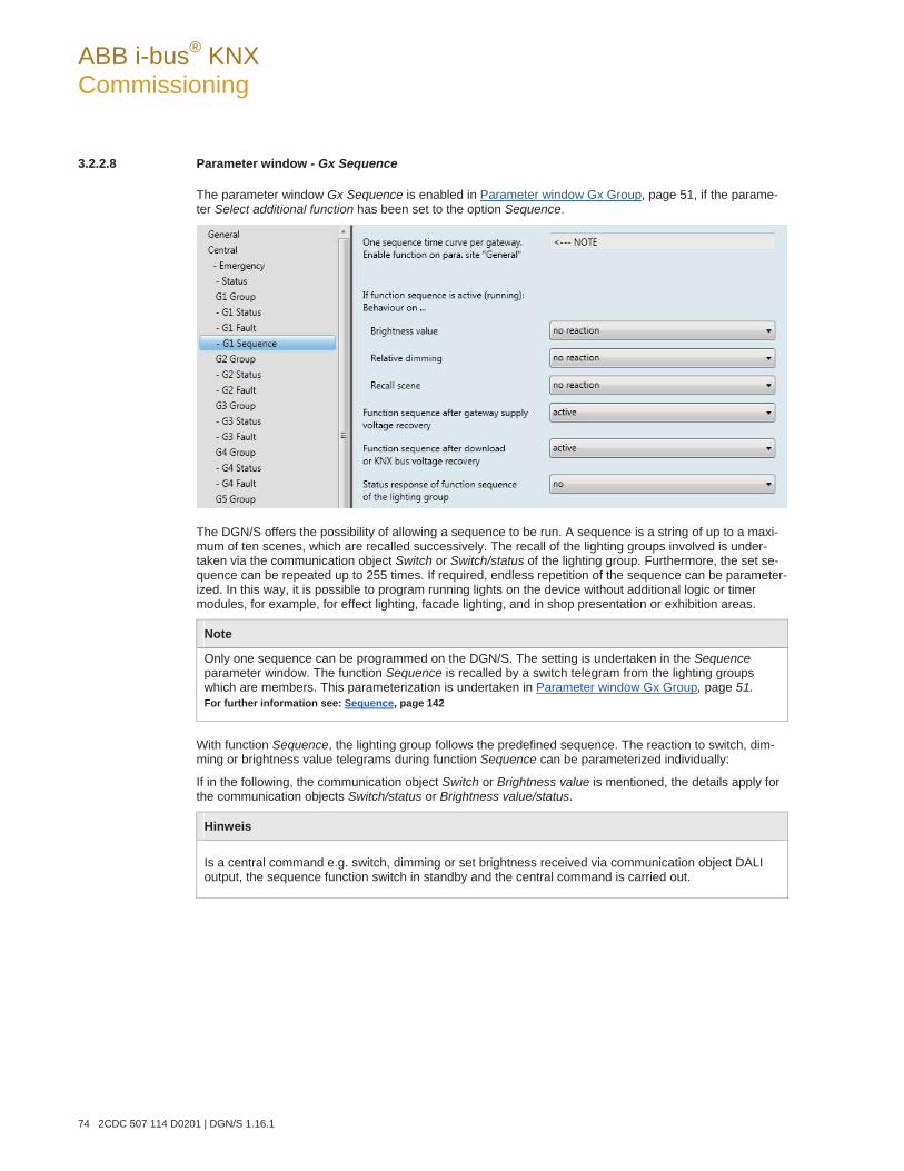
ABB i-bus® KNX Commissioning
74 2CDC 507 114 D0201 | DGN/S 1.16.1
3.2.2.8 Parameter window - Gx Sequence
The parameter window Gx Sequence is enabled in Parameter window Gx Group, page 51, if the parame-ter Select additional function has been set to the option Sequence.
The DGN/S offers the possibility of allowing a sequence to be run. A sequence is a string of up to a maxi-mum of ten scenes, which are recalled successively. The recall of the lighting groups involved is under-taken via the communication object Switch or Switch/status of the lighting group. Furthermore, the set se-quence can be repeated up to 255 times. If required, endless repetition of the sequence can be parameter-ized. In this way, it is possible to program running lights on the device without additional logic or timer modules, for example, for effect lighting, facade lighting, and in shop presentation or exhibition areas.
Note
Only one sequence can be programmed on the DGN/S. The setting is undertaken in the Sequence parameter window. The function Sequence is recalled by a switch telegram from the lighting groups which are members. This parameterization is undertaken in Parameter window Gx Group, page 51. For further information see: Sequence, page 142
With function Sequence, the lighting group follows the predefined sequence. The reaction to switch, dim-ming or brightness value telegrams during function Sequence can be parameterized individually:
If in the following, the communication object Switch or Brightness value is mentioned, the details apply for the communication objects Switch/status or Brightness value/status.
Hinweis Is a central command e.g. switch, dimming or set brightness received via communication object DALI output, the sequence function switch in standby and the central command is carried out.
ABB i-bus® KNX Commissioning
DGN/S 1.16.1 | 2CDC 507 114 D0201 75
If function sequence is active (running): Behaviour on …
Brightness value Options: no reaction
set function in standby
With activated function Sequence, the parameter can be used to define the reaction to a brightness value telegram.
no reaction: A brightness value telegram is ignored.
set function in standby: A brightness telegram ends function Sequence, and the DGN/S carries out the brightness telegram via the communication object Brightness value. The function Se-quence is latent and waits (standby) until a renewed activation via the communication object Activate function Sequence or via an ON telegram to the communication object Switch.
Relative dimming Options: no reaction
set function in standby
With activated function Sequence, the parameter can be used to define the reaction to a dimming telegram on the communication object Relative dimming.
no reaction: A dimming telegram is ignored.
set function in standby: A dimming telegram ends the function Sequence, and the DGN/S car-ries out the dimming telegram. The function Sequence is latent and waits until a renewed acti-vation via the communication object Activate function Sequence or via an ON telegram to the communication object Switch.
Recall scene Options: no reaction
set function in standby
With activated function Sequence the parameter can be used to define the reaction to a scene re-call.
no reaction: A scene recall is ignored.
set function in standby: A scene telegram ends function Sequence, and the DGN/S carries out the scene recall. The function Sequence is latent and waits until a renewed activation via the communication object Activate function Sequence or via an ON telegram to the communication object Switch.
Function sequence after gateway supply voltage recovery Options: inactive
active last status
This parameter defines if function Sequence is active or inactive after gateway supply voltage recovery.
After a Gateway supply voltage recovery, the parameterized brightness value in the Parameter window – Gx Fault, page 64 is set. The function Sequence is then undertaken with the option defined here.
inactive: The function Sequence is not reactivated after gateway operating voltage recovery.
active: The function Sequence is reactivated after gateway operating voltage recovery. The lighting group is started with the next ON telegram.
last status: The function Sequence receives the operating state, which it had before gateway operat-ing voltage failure.
ABB i-bus® KNX Commissioning
76 2CDC 507 114 D0201 | DGN/S 1.16.1
Function sequence after download or KNX bus voltage recovery Options: inactive
active last status
This parameter defines if function Sequence is active or inactive after KNX bus voltage recovery.
After a Gateway supply voltage recovery, the parameterized brightness value in the Parameter window – Gx Fault, page 64 is set. The function Sequence is subsequently undertaken with the option defined here.
inactive: Function Sequence is not activated after a download or after KNX voltage recovery.
active: Function Sequence is activated after a download or after KNX voltage recovery. The lighting group is switched on with the brightness value after KNX voltage recovery and restarted after an ON telegram.
last status: The function Sequence receives the operating state, which it had before download or KNX voltage failure.
Status response of function sequence of the lighting group Options: no
yes: via object "Activate Sequence/Status"
This parameter defines whether the status of the function Sequence of the group is sent on the KNX. For this purpose, the communication object Activate Sequence/Status is enabled.
no: The state of the function Sequence is not actively sent on the KNX.
yes: via object "Activate Sequence/Status": The common communication object Activate Se-quence/Status receives a telegram with the value 1 to activate function Sequence and simultaneously sends the current status of the function Sequence actively on the KNX. It is possible to parameterize when the status is sent on the KNX. The following parameters appear for this purpose:
send object value Options: after a change
after request after a change or request
after a change: The status is sent after a change.
after request: The status is sent after a request.
after a change or request: The status is sent after a change or a request.
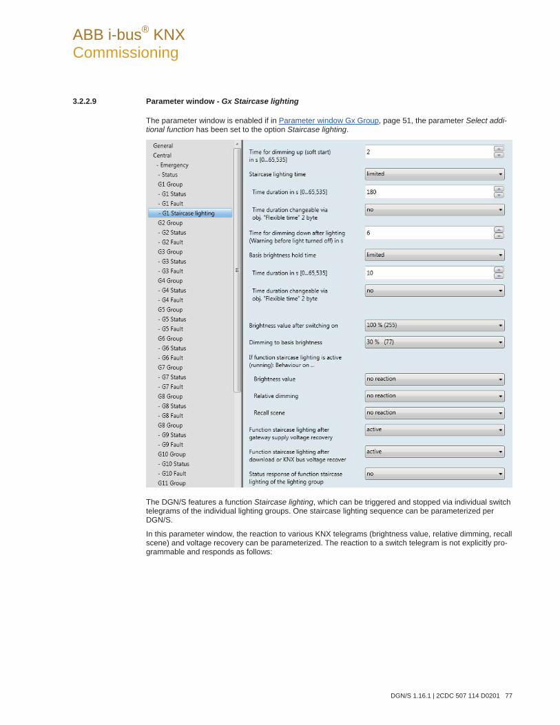
ABB i-bus® KNX Commissioning
DGN/S 1.16.1 | 2CDC 507 114 D0201 77
3.2.2.9 Parameter window - Gx Staircase lighting
The parameter window is enabled if in Parameter window Gx Group, page 51, the parameter Select addi-tional function has been set to the option Staircase lighting.
The DGN/S features a function Staircase lighting, which can be triggered and stopped via individual switch telegrams of the individual lighting groups. One staircase lighting sequence can be parameterized per DGN/S.
In this parameter window, the reaction to various KNX telegrams (brightness value, relative dimming, recall scene) and voltage recovery can be parameterized. The reaction to a switch telegram is not explicitly pro-grammable and responds as follows:
ABB i-bus® KNX Commissioning
78 2CDC 507 114 D0201 | DGN/S 1.16.1
The function Staircase lighting is triggered by an ON telegram to the communication object Switch of a lighting group. With an OFF telegram, the lighting group is controlled with the basis brightness of the func-tion Staircase lighting. The function Staircase lighting remains in standby mode and is started by a re-newed ON telegram. Should the DGN/S receive a renewed ON telegram during ongoing function Staircaselighting, the function Staircase lighting is restarted (retriggered).
The function Staircase light is also started if the DGN/S receives a telegram with the value 1 on the com-munication object Activate fct. Staircase lighting or Act. Staircase lighting/status.
If in the following the communication objects Switch (ON telegram) or Brightness value are mentioned, it also applies for the communication objects Switch/status or Brightness value/status.
Time for dimming up (soft start) in s [0…65,535] Options: 0…2…65535
This parameter determines the time duration, in which the DGN/S dims to the brightness value for the staircase time. The function Staircase lighting is switched on with a soft start.
Staircase lighting time Options: limited
unlimited
This parameter determines whether the staircase light is automatically shut off after a programmable time or whether a brightness value is applied. The function Staircase lighting is no longer switched off automati-cally after Gateway supply voltage recovery.
limited: The staircase lighting time is ended after a certain time, which can be set with both the follow-ing parameters.
unlimited: The function Staircase lighting is no longer switched off automatically. The brightness value is changed only if a new telegram is received via the KNX or by forced operation, e.g. with a fault whe-re the brightness value is changed.
Time duration in s [0…65,535] Options: 0…180…65,535
This is the time duration, for which the function Staircase lighting remains switched on for the light-ing group.
Time duration changeable via obj. "Flexible time" 2 byte Options: yes
no
The time received via the communication object Flexible time has an effect on the time duration of the staircase lighting. The flexible dimming time has a value between 0…65,535 seconds.
yes: The time received via the central communication object (DALI output) Flexible time is used as the time duration for the staircase lighting.
no: The time duration for staircase lighting cannot be changed via KNX.
ABB i-bus® KNX Commissioning
DGN/S 1.16.1 | 2CDC 507 114 D0201 79
Time for dimming down after lighting (Warning before light turned off) in s Options: 0…6…65,535
This parameter determines the duration, in which the DGN/S dims the brightness value of the staircase lighting time in order to indicate that the staircase lighting will end.
Basis brightness hold time Options: limited
unlimited
This parameter determines whether the basis brightness is permanently present or whether the lighting is switched off after a certain time.
limited: The basis brightness ends after certain time and the lighting is switched off. Parameterization of the time is undertaken with both of the following parameters.
unlimited: The basis brightness is no longer switched off automatically. The brightness value is chan-ged only if a new telegram is received via the KNX or by forced operation, e.g. with a fault where the brightness value is changed.
Time duration in s [0…65,535] Options: 0…10…65,535
This is the time duration, after which the basis brightness is switched off.
Time duration changeable via obj. "Flexible time" 2 Byte Options: yes
no
The time received via the communication object Flexible time has an effect on the time duration of the basis brightness. The flexible dimming time has a value between 0…65,535 seconds.
yes: The time received via the central communication object (DALI output) Flexible time is used for the time duration of the basis brightness.
no: The time duration for the basis brightness cannot be changed via KNX.
Brightness value after switching on Options: 100 % (255)
… 0 % (OFF)
This parameter defines the brightness value for operating function Staircase lighting, which is set after the dimming up phase and before dimming down (pre-warning phase).
Note
If flexible time is used, the time is used directly after download. If no flexible time is written via KNX before, the value is 0
ABB i-bus® KNX Commissioning
80 2CDC 507 114 D0201 | DGN/S 1.16.1
Dimming to basis brightness Options: 100 % (255)
… 30 % (77) … 0 % (OFF)
This parameter defines the brightness value after the staircase lighting time has timed out. It is the bright-ness value set after the dimming down time (pre-warning phase). The basis brightness hold time as well as the time for dimming down after light on (Warning before light turned off) is programmable in the Parameter window - Gx Staircase lighting on page 90.
Example
A typical application for a basis brightness is for example, in nursing homes or residential care homes in hallways, where the lighting is never fully switched off. A basis brightness of approx. 20 % should always exist. If a patient enters the area, it should be illuminated for a certain time (staircase lighting time) with maximum brightness (100 %).
If function staircase light is active (running): Behaviour on …
Brightness value Options: no reaction
set function in standby
With activated function Staircase lighting, the parameter can be used to define the reaction to a brightness value telegram.
no reaction: A brightness value telegram is ignored.
set function in standby: A brightness telegram ends function Staircase lighting, and the DGN/S carries out the brightness telegram via the communication object Brightness value. The func-tion Staircase lighting is latent and waits until a renewed activation via the communication ob-ject function Activate fct. Staircase lighting or via an ON telegram to the communication object Switch.
Relative dimming Options: no reaction
set function in standby
With activated function Staircase lighting, the parameter can be used to define the reaction to dim-ming telegram to the communication object Relative dimming.
no reaction: A dimming telegram is ignored.
set function in standby: A dimming telegram ends function Staircase lighting, and the DGN/S carries out the dimming telegram. The function Staircase lighting is latent and waits until a re-newed activation via the communication object function Activate fct. Staircase lighting or via an ON telegram to the communication object Switch.
ABB i-bus® KNX Commissioning
DGN/S 1.16.1 | 2CDC 507 114 D0201 81
Recall scene Options: no reaction
set function in standby
With activated function Staircase lighting, the parameter can be used to define the reaction to a scene recall.
no reaction: A scene recall is ignored.
set function in standby: A scene telegram ends function Staircase lighting, and the DGN/S car-ries out the scene recall. The function Staircase lighting is latent and waits until a renewed ac-tivation via the communication object function Activate fct. Staircase lighting or via an ON tele-gram to the communication object Switch.
Function staircase lighting after gateway supply voltage recovery Options: inactive
active last status
This parameter defines if function Staircase lighting is active or inactive after gateway supply voltage re-covery.
After a gateway supply voltage recovery, the parameterized brightness value in the Parameter window – Gx Fault, page 64 is set. The function Staircase lighting is then undertaken with the option defined here.
inactive: The function Staircase lighting is not reactivated after gateway operating voltage recovery.
active: The function Staircase lighting is reactivated after gateway operating voltage recovery. The lighting group is set using the parameterized basis brightness and can be started by an ON telegram or renewed activation via the communication object Activate fct. Staircase lighting.
last status: The function Staircase lighting receives the operating state, which it had before gateway operating voltage failure.
Note
A staircase lighting time in operation before the gateway supply voltage failure is not automatically restarted. The lighting group is in standby mode with the basis brightness. The function Staircase lighting will be started only after an ON telegram with the value 1 has been received on the communica-tion object Switch.
HinweisIs a central command e.g. switch, dimming or set brightness received via communication object DALI output, the staircase function switch in standby and the central command is carried out.
ABB i-bus® KNX Commissioning
82 2CDC 507 114 D0201 | DGN/S 1.16.1
Function staircase lighting after download or KNX bus voltage recovery Options: inactive
active last status
This parameter defines if function Staircase light is active or inactive after KNX voltage recovery.
After a gateway supply voltage recovery, the parameterized brightness value in the Parameter window – Gx Fault, page 64 is set. The function Staircase light is then undertaken with the option defined here.
last status: The function Staircase lighting receives the operating state, which it had before download or KNX voltage failure.
active: The function Staircase lighting is activated after a download or after KNX voltage recovery. The lighting group is set using the parameterized basis brightness and can be started by an ON telegram or renewed activation via the communication object Activate fct. Staircase lighting.
inactive: The function Staircase lighting is not activated after a download of after KNX voltage recov-ery.
Note
A staircase light in operation before the download is not automatically restarted. The lighting group is in standby mode with the basis brightness. The function Staircase lighting will be started only after an ON telegram with the value 1 has been received on the communication object Switch. With KNX voltage failure, the parameterized brightness value at KNX voltage failure is initially set in the parameter window Parameter window – Gx Fault, page 64. An interrupted staircase light is continued.
Status response of function staircase lighting of the lighting group Options: no
yes: via object "Act. Staircase lighting/status"
This parameter defines whether the status of the function Staircase lighting of the lighting group is sent on the KNX. For this purpose, the communication object Act. Staircase lighting/status is enabled.
no: The state of the function Staircase lighting is not actively sent on the KNX.
yes: via object "Act. Staircase lighting/status": The common communication object Act. Staircase light-ing/status receives a telegram with the 1 to activate function Staircase lighting and simultaneously sends the current status of the function Staircase lighting actively on the KNX. It is possible to param-eterize when the status is sent on the KNX. The following parameters appear.
Note
The status of the function Staircase lighting indicates whether the lighting group operates normally and if it can be switched on or off by a switch telegram to the communication object Switch, or if a telegram to the communication object Switch triggers the function Staircase lighting. The status of the function Staircase lighting has nothing to do with the state of the function Staircaselighting, whether it is currently operating or in standby mode.
ABB i-bus® KNX Commissioning
DGN/S 1.16.1 | 2CDC 507 114 D0201 83
send object value Options: after a change
after request after a change or request
after a change: The status is sent after a change.
after request: The status is sent after a request.
after a change or request: The status is sent after a change or a request.
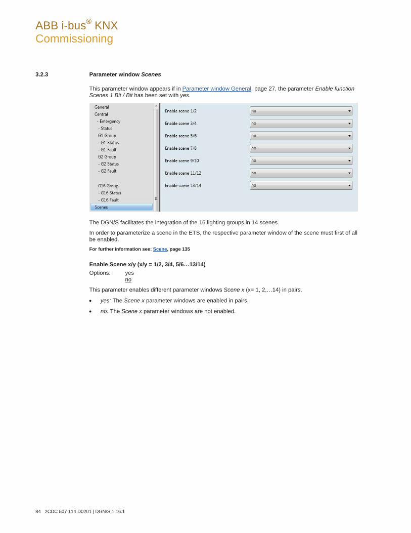
ABB i-bus® KNX Commissioning
84 2CDC 507 114 D0201 | DGN/S 1.16.1
3.2.3 Parameter window Scenes
This parameter window appears if in Parameter window General, page 27, the parameter Enable function Scenes 1 Bit / Bit has been set with yes.
The DGN/S facilitates the integration of the 16 lighting groups in 14 scenes.
In order to parameterize a scene in the ETS, the respective parameter window of the scene must first of all be enabled. For further information see: Scene, page 135
Enable Scene x/y (x/y = 1/2, 3/4, 5/6…13/14) Options: yes
no
This parameter enables different parameter windows Scene x (x= 1, 2,…14) in pairs.
yes: The Scene x parameter windows are enabled in pairs.
no: The Scene x parameter windows are not enabled.
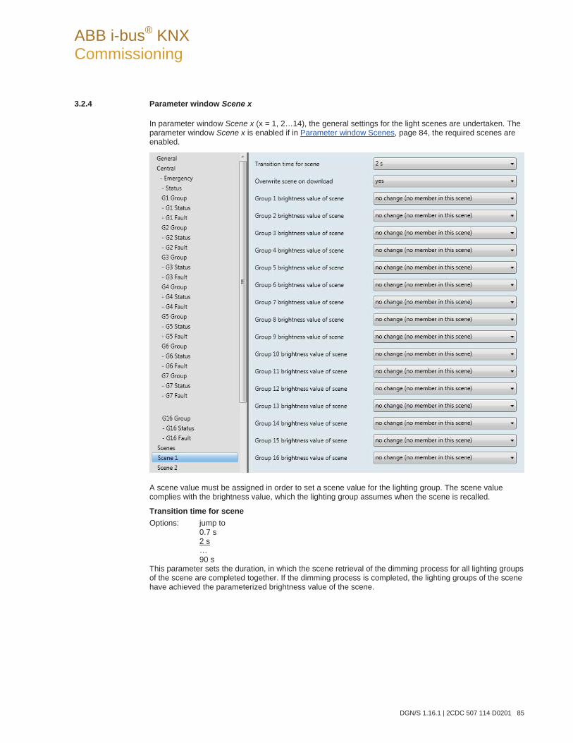
ABB i-bus® KNX Commissioning
DGN/S 1.16.1 | 2CDC 507 114 D0201 85
3.2.4 Parameter window Scene x
In parameter window Scene x (x = 1, 2…14), the general settings for the light scenes are undertaken. The parameter window Scene x is enabled if in Parameter window Scenes, page 84, the required scenes are enabled.
A scene value must be assigned in order to set a scene value for the lighting group. The scene value complies with the brightness value, which the lighting group assumes when the scene is recalled.
Transition time for scene Options: jump to
0.7 s 2 s … 90 s
This parameter sets the duration, in which the scene retrieval of the dimming process for all lighting groups of the scene are completed together. If the dimming process is completed, the lighting groups of the scene have achieved the parameterized brightness value of the scene.
ABB i-bus® KNX Commissioning
86 2CDC 507 114 D0201 | DGN/S 1.16.1
Example
Lighting group 1, which is dimmed from 10 % to 100 %, and lighting group 2, which is dimmed from 90 % to 100 %, achieve the parameterized brightness value of the scene simultaneously.
jump to: When a scene is recalled, the lighting groups are switched on immediately with the param-
eterized brightness value of the scene.
0.7 s…90 s: When a scene is recalled, all lighting groups of the scene are dimmed from their current brightness value to the parameterised brightness value within this time duration.
Overwrite scene on download Options: yes
no
yes: The scene values and the scene transition times in the DALI devices of the lighting group are overwritten after a download or after KNX voltage recovery by the values set in the ETS.
no: The scene values and the scene transition times in the DALI devices of the lighting group are not overwritten after a download or after KNX voltage recovery by the values set in the ETS. If no scene values have been stored, they are parameterized by the DGN/S to the maximum brightness.
Note
With a recall scene or with a store scene, only the lighting groups, which are constituents of the scene, are taken into consideration.
Group x brightness value of scene (x = 1…16) Options: no change (no member in this scene)
100 % (255) … 0 % (OFF)
Note
The options 100 % (255)…0 % (OFF) are only visible if the parameter Overwrite scene on download is set to yes. With the option no, the possible settings are reduced to no change (no member in this scene) and member in this scene.
This parameter defines the brightness value that is set in the lighting group when a scene is recalled.
no change (no member in this scene): This lighting group does not belong in this scene. During a sce-ne recall, the lighting group is not influenced. The current brightness value of the lighting group re-mains unchanged and even when the scene is stored via the KNX, the brightness value of this group is not stored.
100 % (255)…0 % (OFF): The lighting group belongs to the scene. During a scene recall, the lighting group is set to the parameterized brightness value here. If the set brightness value is above or below the set maximum or minimum brightness value of the respective lighting group (see Parameter win-dow Gx Group, page 51), the respective brightness value is saved in the scene.
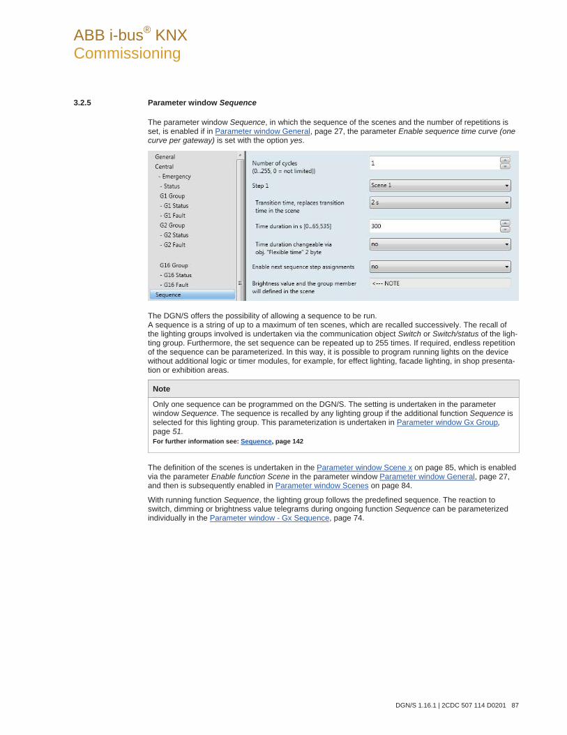
ABB i-bus® KNX Commissioning
DGN/S 1.16.1 | 2CDC 507 114 D0201 87
3.2.5 Parameter window Sequence
The parameter window Sequence, in which the sequence of the scenes and the number of repetitions is set, is enabled if in Parameter window General, page 27, the parameter Enable sequence time curve (one curve per gateway) is set with the option yes.
The DGN/S offers the possibility of allowing a sequence to be run. A sequence is a string of up to a maximum of ten scenes, which are recalled successively. The recall of the lighting groups involved is undertaken via the communication object Switch or Switch/status of the ligh-ting group. Furthermore, the set sequence can be repeated up to 255 times. If required, endless repetition of the sequence can be parameterized. In this way, it is possible to program running lights on the device without additional logic or timer modules, for example, for effect lighting, facade lighting, in shop presenta-tion or exhibition areas.
Note
Only one sequence can be programmed on the DGN/S. The setting is undertaken in the parameter window Sequence. The sequence is recalled by any lighting group if the additional function Sequence is selected for this lighting group. This parameterization is undertaken in Parameter window Gx Group,page 51. For further information see: Sequence, page 142
The definition of the scenes is undertaken in the Parameter window Scene x on page 85, which is enabled via the parameter Enable function Scene in the parameter window Parameter window General, page 27, and then is subsequently enabled in Parameter window Scenes on page 84.
With running function Sequence, the lighting group follows the predefined sequence. The reaction to switch, dimming or brightness value telegrams during ongoing function Sequence can be parameterized individually in the Parameter window - Gx Sequence, page 74.
ABB i-bus® KNX Commissioning
88 2CDC 507 114 D0201 | DGN/S 1.16.1
Number of cycles (0...255, 0 = not limited) Options: 0, 1…255
The sequence mode is triggered by an ON telegram with the value 1 on the communication object Switch or Switch/status of a lighting group.
This parameter defines how often a sequence should be repeated.
0: The sequence is repeated continuously. An interruption can be performed in accordance with the parameterization by an OFF telegram to one of the communication objects of the lighting group. The setting is undertaken in the Parameter window - Gx Sequence, page 74.
1…255: This is the number of repetitions of a sequence. An interruption can be performed in accor-dance with the parameterization by an OFF telegram to one of the communication objects of the light-ing group. The setting is undertaken in the Parameter window - Gx Sequence, page 74.
Step x1)
1) x = 1 to 10 and represents a step in the sequence Options: Scene 1
… Scene 14
This parameter determines the scene, which is used by the DGN/S, for step x of the sequence. This scene is recalled during a sequence run or during its repetition as a brightness value for scene x. A scene can be assigned to several sequence stages.
Note
In the scene, the brightness value and lighting groups, which are controlled with sequence step x, are parameterized. The transition time is the speed, at which the brightness value is set, and the runtime is the length of time, for which the brightness value is retained, and they are set with both the following parameters (Transition time and runtime). The Transition time for the scene parameterized in the parameter window Scene does not have an influence on the course of the sequence.
Transition time, replaces transition time in the scene Options: jump to
0.7 s 2 s … 90 s
This parameter determines the time duration, in which the DGN/S approaches the brightness value for the scene step. The brightness value is defined in the parameter window (Scene value) Scene.
jump to: The lighting groups, which are defined for this sequence step, switch on immediately.
0.7 s…90 s: In this period, all lighting groups are dimmed to the parameterized brightness va-lue.
ABB i-bus® KNX Commissioning
DGN/S 1.16.1 | 2CDC 507 114 D0201 89
Time duration in s [0…65,535] Options: 0…300…65,535
In this period, the lighting groups of this sequence step assume the parameterized brightness val-ues in the scene.
no limitation: The brightness value (scene values of the lighting group) remains set for an unli-mited period. The brightness value is only changed if a new telegram is received via the KNX.
Time duration changeable via obj. "Flexible time" 2 Byte Options: yes
no
The time received via the communication object Flexible time has an effect on the time duration of the sequence. The flexible dimming time has a value between 0…65,535 seconds.
yes: The time received via the central communication object (DALI output) Flexible time is used for the time duration of the sequence.
no: The time duration for the sequence cannot be changed via KNX.For further information see Communication object no. 27 page 112.
Enable next sequence step assignments Options: yes
no
With this parameter, a further sequence step can be enabled. A maximum of 10 steps are possible.
no: No further sequence step is enabled.
yes: A further sequence step is enabled.
Brightness value and the group member will defined in the scene < NOTE
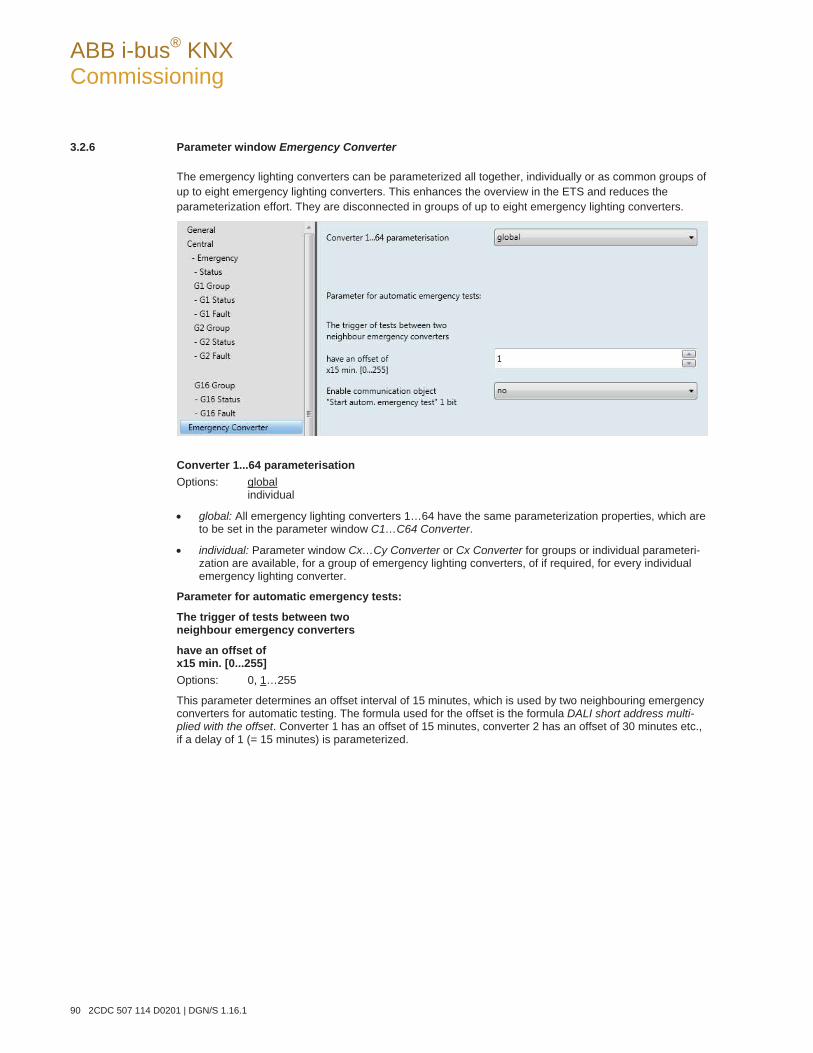
ABB i-bus® KNX Commissioning
90 2CDC 507 114 D0201 | DGN/S 1.16.1
3.2.6 Parameter window Emergency Converter
The emergency lighting converters can be parameterized all together, individually or as common groups of up to eight emergency lighting converters. This enhances the overview in the ETS and reduces the parameterization effort. They are disconnected in groups of up to eight emergency lighting converters.
Converter 1...64 parameterisation Options: global
individual
global: All emergency lighting converters 1…64 have the same parameterization properties, which are to be set in the parameter window C1…C64 Converter.
individual: Parameter window Cx…Cy Converter or Cx Converter for groups or individual parameteri-zation are available, for a group of emergency lighting converters, of if required, for every individual emergency lighting converter.
Parameter for automatic emergency tests:
The trigger of tests between two neighbour emergency converters
have an offset of x15 min. [0...255] Options: 0, 1…255
This parameter determines an offset interval of 15 minutes, which is used by two neighbouring emergency converters for automatic testing. The formula used for the offset is the formula DALI short address multi-plied with the offset. Converter 1 has an offset of 15 minutes, converter 2 has an offset of 30 minutes etc., if a delay of 1 (= 15 minutes) is parameterized.
ABB i-bus® KNX Commissioning
DGN/S 1.16.1 | 2CDC 507 114 D0201 91
This parameter refers to the automatic emergency lighting test, which is undertaken autonomously (op-tional) by the emergency lighting converters (device type 1 to EN 62386-202). This offset can be used to avoid that all emergency lighting lamps are simultaneously in the test or recharging cycles after a test. The offset for the start of the automatic test is integrated into the emergency lighting converter with a time in-terval of 15 minutes. The DGN/S can only set this time but is not responsible for the timing tolerances that the emergency lighting converter uses to implement this time. It is also necessary to consider that a test is not undertaken immediately, if an emergency lighting lamp is in the recharging cycle after a test. The de-mand (trigger) for a test by the DGN/S remains and will be triggered by the emergency lighting converter when it is again ready for operation.
You can set whether an automatic emergency lighting test is to be undertaken by the emergency lighting converter in the Parameter window - Cx…Cy Test on page 95.
Due to the different, partly very large tolerances of the emergency lighting converter, control of the tests by a higher-level emergency lighting centre is preferred to the automatic emergency lighting test. The start request of an emergency lighting test is passed on via the DGN/S with the corresponding converter on the emergency lighting converter (see Communication objects Converter x, page 122).
Further parameters for selection appear with the option individual, which determine whether the emer-gency lighting converters are parameterized individually or in groups of 8 emergency lighting converters:
Enable communication object "Start autom. emergency test" 1 bit Options: yes
no
yes: The start request of the automatic emergency lighting test is passed on from the DGN/S to the emergency lighting converter.
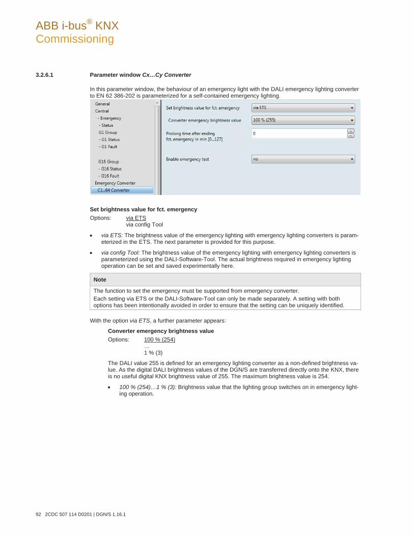
ABB i-bus® KNX Commissioning
92 2CDC 507 114 D0201 | DGN/S 1.16.1
3.2.6.1 Parameter window Cx…Cy Converter
In this parameter window, the behaviour of an emergency light with the DALI emergency lighting converter to EN 62 386-202 is parameterized for a self-contained emergency lighting.
Set brightness value for fct. emergency Options: via ETS
via config Tool
via ETS: The brightness value of the emergency lighting with emergency lighting converters is param-eterized in the ETS. The next parameter is provided for this purpose.
via config Tool: The brightness value of the emergency lighting with emergency lighting converters is parameterized using the DALI-Software-Tool. The actual brightness required in emergency lighting operation can be set and saved experimentally here.
Note
The function to set the emergency must be supported from emergency converter. Each setting via ETS or the DALI-Software-Tool can only be made separately. A setting with both options has been intentionally avoided in order to ensure that the setting can be uniquely identified.
With the option via ETS, a further parameter appears:
Converter emergency brightness value Options: 100 % (254)
… 1 % (3)
The DALI value 255 is defined for an emergency lighting converter as a non-defined brightness va-lue. As the digital DALI brightness values of the DGN/S are transferred directly onto the KNX, there is no useful digital KNX brightness value of 255. The maximum brightness value is 254.
100 % (254)…1 % (3): Brightness value that the lighting group switches on in emergency light-ing operation.
ABB i-bus® KNX Commissioning
DGN/S 1.16.1 | 2CDC 507 114 D0201 93
Prolong time after ending fct. emergency in min [0…127]
Options: 1…6…128
This parameter determines the duration in minutes, which the emergency lighting lights with the brightness value in emergency lighting operation.
Enable emergency test Options: yes
no
This parameter enables the emergency lighting tests by the emergency lighting converter and the respec-tive parameter window C1 Test.
yes: The parameter window C1 Test is enabled. Using the DGN/S, the tests for the emergency lighting with the emergency lighting converter to EN 62 386-202 are determined. Two further parameters ap-pear:
no: No tests for the emergency lighting with emergency lighting converter are carried out.
Time period in which emergency test must be started, in days [0...255] Options: 1…7…255
It can occur that a requested emergency lighting test cannot be undertaken immediately by the emergency lighting converter, e.g. because the emergency lighting battery is discharged. This pa-rameter determines how long the test telegram should remain active. If a test cannot be started, a message is issued. Parameterization is undertaken in days.
Note
Undertaking of the emergency lighting test cannot be guaranteed. The start of the test is a reserved indicator that the test should be started as quickly as possible from the converter. If this is not possible for technical reasons, the request remains active. The test starts at the next possible time. The corresponding state is detected by communication object Emergency test trigger/status (no. 169).
ABB i-bus® KNX Commissioning
94 2CDC 507 114 D0201 | DGN/S 1.16.1
Enable coded status emergency test Options: yes
no
This parameter enables the 1 byte communication object Emergency test trigger/status. This com-munication object indicates a fault of the emergency lighting converter on the KNX.
yes: The communication object Emergency test trigger/status is enabled. The communication object sends a coded telegram, which triggers an emergency lighting test and sends its status on the KNX. The coding can be taken from the description of the communication object Emergency test status, page 115.
no: No emergency lighting test is triggered by the DGN/S using an individual communication object.
With the option yes, two further parameters appear:
send object value Options: after a change
after request after a change or request
after a change: The status is sent after a change.
after request: The status is sent after a request.
after a change or request: The status is sent after a change or a request.
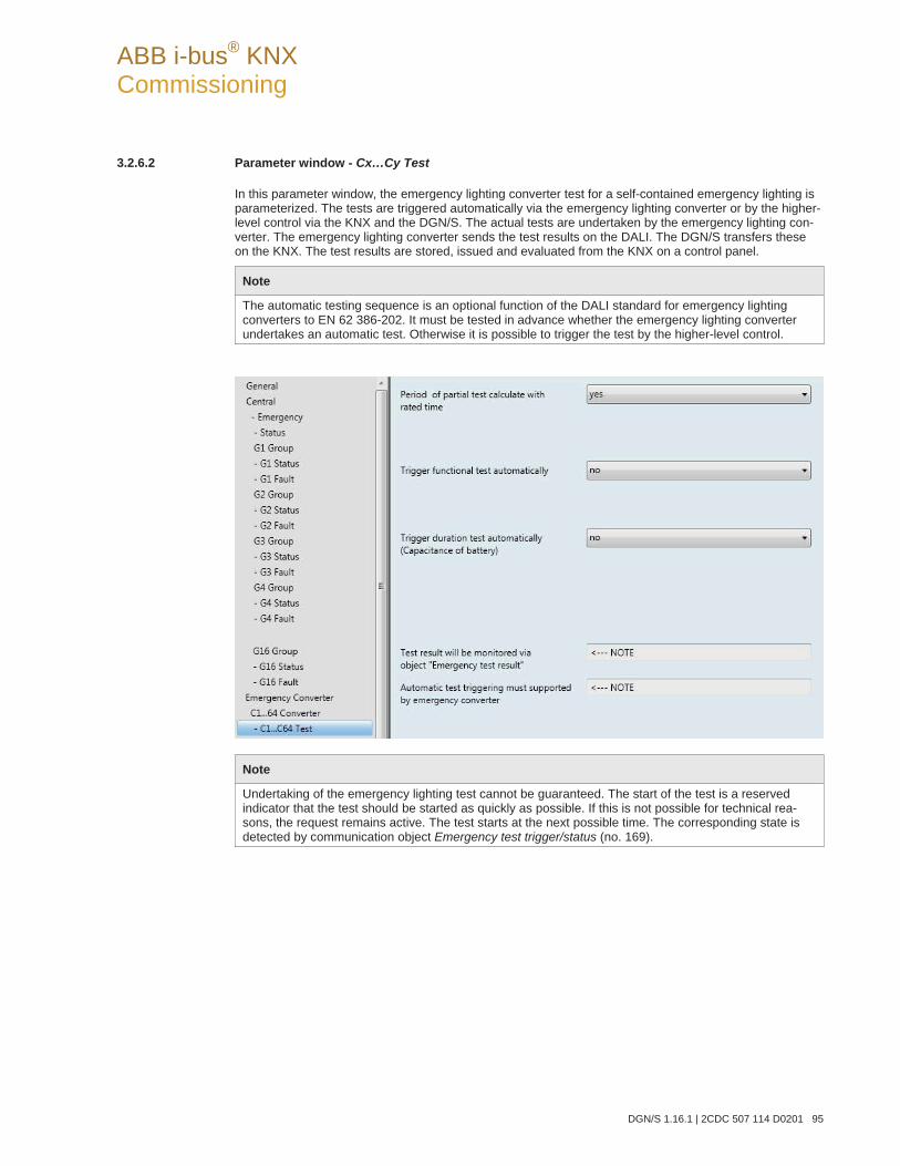
ABB i-bus® KNX Commissioning
DGN/S 1.16.1 | 2CDC 507 114 D0201 95
3.2.6.2 Parameter window - Cx…Cy Test
In this parameter window, the emergency lighting converter test for a self-contained emergency lighting is parameterized. The tests are triggered automatically via the emergency lighting converter or by the higher-level control via the KNX and the DGN/S. The actual tests are undertaken by the emergency lighting con-verter. The emergency lighting converter sends the test results on the DALI. The DGN/S transfers these on the KNX. The test results are stored, issued and evaluated from the KNX on a control panel.
Note
The automatic testing sequence is an optional function of the DALI standard for emergency lighting converters to EN 62 386-202. It must be tested in advance whether the emergency lighting converter undertakes an automatic test. Otherwise it is possible to trigger the test by the higher-level control.
Note
Undertaking of the emergency lighting test cannot be guaranteed. The start of the test is a reserved indicator that the test should be started as quickly as possible. If this is not possible for technical rea-sons, the request remains active. The test starts at the next possible time. The corresponding state is detected by communication object Emergency test trigger/status (no. 169).
ABB i-bus® KNX Commissioning
96 2CDC 507 114 D0201 | DGN/S 1.16.1
Period of partial test calculate with rated time Options: yes
no
The period for the partial test is independent of whether the partial duration test is triggered automatically or manually via a communication object.
yes: The DGN/S reads from the emergency lighting converter the rated duration of the battery and calculates (plus 10 % duration rating), from these values, the time duration for the partial duration test.
no: No automatic duration or partial duration test is intended for the emergency lighting converter. For further information see: Partial duration test, page 10
With the option no, a further parameter appears:
Period of partial test in 2x min [2...255] Options: 2…35…255
This parameter defines the time duration of the partial test. The set value is multiplied by 2 in order to obtain the result, e.g. with the default value 35 the partial duration test takes 70 minutes.
Trigger functional test automatically Options: yes
no
yes: The emergency lighting converter starts the functional test automatically and passes on the in-formation via the DALI to the DGN/S. The start of the functional test is executed in a fixed interval.
Note
Automatic starting of the functional test after a fixed interval is an optional function stated in the stan-dard for an emergency lighting converter. It must be decided in advance whether the emergency lighting converters should support the automatic testing properties.
no: No automatic functional test is intended for the emergency lighting converter.
With the option yes, a further parameters appear:
Test cycle in days [1…255] Options: 1…7…255
This parameter determines the time interval that is automatically used by the function test with the emergency lighting converter. The default value of 7 is set before delivery of the emergency lighting converter.
ABB i-bus® KNX Commissioning
DGN/S 1.16.1 | 2CDC 507 114 D0201 97
Trigger duration test automatically (Capacitance of battery) Options: yes
no
yes: The emergency lighting converter automatically starts an duration or partial duration test and passes on the test result via the DALI tom the DGN/S and thus on the KNX. The start of the test is executed in a fixed interval.
Note
Automatic starting of the functional test after a fixed interval is an optional function stated in the stan-dard for an emergency lighting converter. It must be decided in advance whether the emergency lighting converters should support the automatic testing properties.
no: No automatic duration or partial duration test is intended for the emergency lighting converter.
With the option yes, two further parameters appear:
Test mode Options: duration test
partial duration test duration and partial test
duration test: The emergency lighting converter automatically starts a duration test. The start of the test is executed in a fixed interval. The test cycle is to be set with the parameter Test period in weeks [1...97] in this parameter window.
partial duration test: The emergency lighting converter automatically starts a partial duration test. The start of the test is executed in a fixed interval. The test cycle is to be set with the pa-rameter Test period in weeks [1...97] in this parameter window.
duration and partial test: The emergency lighting converter automatically starts a partial dura-tion and duration test. The start of the test is executed in a fixed interval. The test cycle is to be set with the parameter Test period in weeks [1...97] in this parameter window. Additionally, a further parameter determines which of the tests is a duration test
Test period in weeks [1…97]
Options: 1…52…97
This parameter determines the time interval that is automatically used to start the duration test or partial duration test by the emergency lighting converter. The default value for the partial duration test is 4 weeks. The default value for the duration test is 52 weeks.
With the option duration and partial test a further parameter appears:
Which test number is a duration test [2...100] Options: 2…12…100
This parameter determines during the alternating duration and partial duration testing, after how many tests a duration test is to be performed.
Test result will be monitored via object "Emergency test result“ < NOTE
Automatic test triggering must supported by emergency converter < NOTE
ABB i-bus® KNX Commissioning
98 2CDC 507 114 D0201 | DGN/S 1.16.1
3.3 Communication objects
In this chapter, the communication objects, which the DALI Gateway with Emergency Lighting Function DGN/S 1.16.1 features, are described. The description is divided into blocks, which relate to the name of the communication object.
General - Communication objects for the entire DGN/S
DALI output - Communication objects which relate to the entire DALI output
Group x - Communication objects for a lighting group x
Converter x - Communication objects for an emergency lighting converter x
Scene x - Communication objects for the function Scene
In order to obtain a quick overview of the function possibilities of the DGN/S, all communication objects are listed in an overview table. The detailed function can be examined in more detail in the subsequent de-scription of the individual communication objects.
Note
Some communication objects are dynamic and are only visible if the corresponding parameters are activated in the application software. In the following description, Group x represents a lighting group, Converter x an emergency lighting converter, and Scene x any scene x.
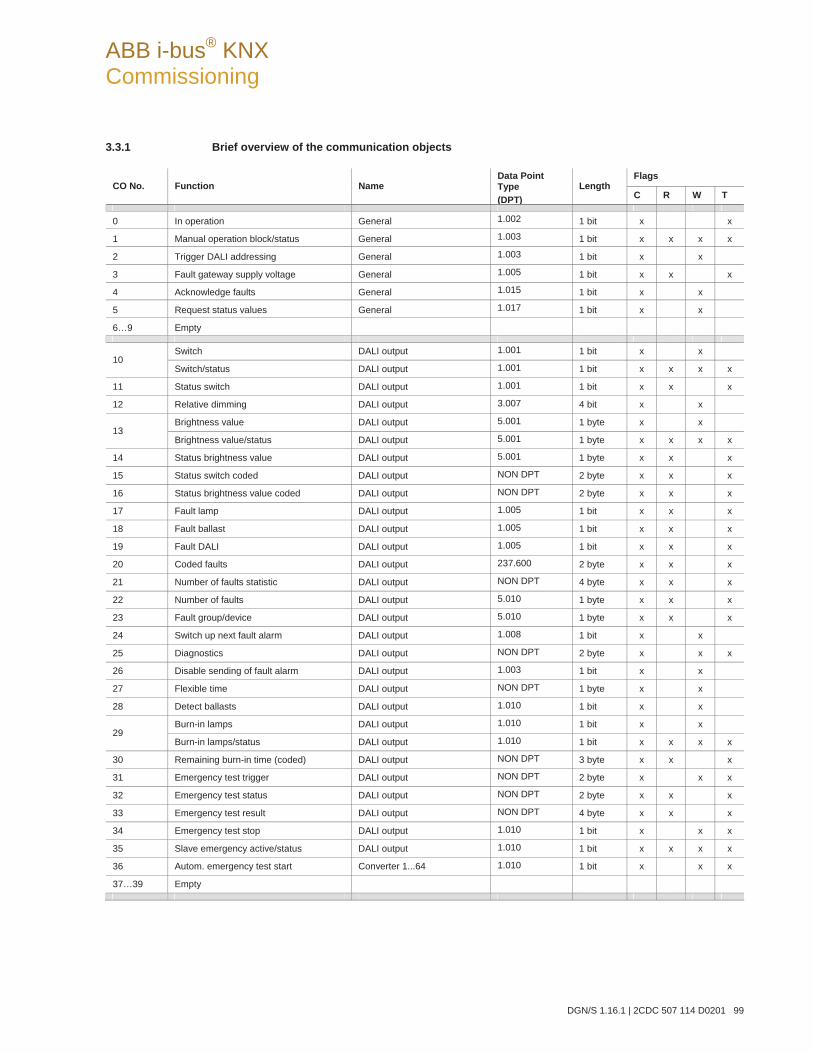
ABB i-bus® KNX Commissioning
DGN/S 1.16.1 | 2CDC 507 114 D0201 99
3.3.1 Brief overview of the communication objects
Flags CO No. Function Name
Data Point Type (DPT)
Length C R W T
0 In operation General 1.002 1 bit x x
1 Manual operation block/status General 1.003 1 bit x x x x
2 Trigger DALI addressing General 1.003 1 bit x x
3 Fault gateway supply voltage General 1.005 1 bit x x x
4 Acknowledge faults General 1.015 1 bit x x
5 Request status values General 1.017 1 bit x x
6…9 Empty
Switch DALI output 1.001 1 bit x x 10
Switch/status DALI output 1.001 1 bit x x x x
11 Status switch DALI output 1.001 1 bit x x x
12 Relative dimming DALI output 3.007 4 bit x x
Brightness value DALI output 5.001 1 byte x x 13
Brightness value/status DALI output 5.001 1 byte x x x x
14 Status brightness value DALI output 5.001 1 byte x x x
15 Status switch coded DALI output NON DPT 2 byte x x x
16 Status brightness value coded DALI output NON DPT 2 byte x x x
17 Fault lamp DALI output 1.005 1 bit x x x
18 Fault ballast DALI output 1.005 1 bit x x x
19 Fault DALI DALI output 1.005 1 bit x x x
20 Coded faults DALI output 237.600 2 byte x x x
21 Number of faults statistic DALI output NON DPT 4 byte x x x
22 Number of faults DALI output 5.010 1 byte x x x
23 Fault group/device DALI output 5.010 1 byte x x x
24 Switch up next fault alarm DALI output 1.008 1 bit x x
25 Diagnostics DALI output NON DPT 2 byte x x x
26 Disable sending of fault alarm DALI output 1.003 1 bit x x
27 Flexible time DALI output NON DPT 1 byte x x
28 Detect ballasts DALI output 1.010 1 bit x x
Burn-in lamps DALI output 1.010 1 bit x x 29
Burn-in lamps/status DALI output 1.010 1 bit x x x x
30 Remaining burn-in time (coded) DALI output NON DPT 3 byte x x x
31 Emergency test trigger DALI output NON DPT 2 byte x x x
32 Emergency test status DALI output NON DPT 2 byte x x x
33 Emergency test result DALI output NON DPT 4 byte x x x
34 Emergency test stop DALI output 1.010 1 bit x x x
35 Slave emergency active/status DALI output 1.010 1 bit x x x x
36 Autom. emergency test start Converter 1...64 1.010 1 bit x x x
37…39 Empty
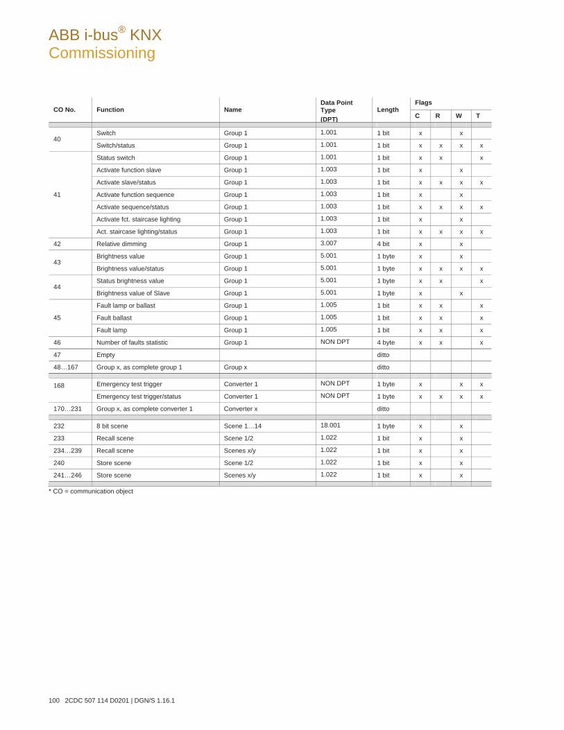
ABB i-bus® KNX Commissioning
100 2CDC 507 114 D0201 | DGN/S 1.16.1
Flags CO No. Function Name
Data Point Type (DPT)
Length C R W T
Switch Group 1 1.001 1 bit x x 40
Switch/status Group 1 1.001 1 bit x x x x
Status switch Group 1 1.001 1 bit x x x
Activate function slave Group 1 1.003 1 bit x x
Activate slave/status Group 1 1.003 1 bit x x x x
Activate function sequence Group 1 1.003 1 bit x x
Activate sequence/status Group 1 1.003 1 bit x x x x
Activate fct. staircase lighting Group 1 1.003 1 bit x x
41
Act. staircase lighting/status Group 1 1.003 1 bit x x x x
42 Relative dimming Group 1 3.007 4 bit x x
Brightness value Group 1 5.001 1 byte x x 43
Brightness value/status Group 1 5.001 1 byte x x x x
Status brightness value Group 1 5.001 1 byte x x x 44
Brightness value of Slave Group 1 5.001 1 byte x x
Fault lamp or ballast Group 1 1.005 1 bit x x x
Fault ballast Group 1 1.005 1 bit x x x 45
Fault lamp Group 1 1.005 1 bit x x x
46 Number of faults statistic Group 1 NON DPT 4 byte x x x
47 Empty ditto
48…167 Group x, as complete group 1 Group x ditto
Emergency test trigger Converter 1 NON DPT 1 byte x x x 168 Emergency test trigger/status Converter 1 NON DPT 1 byte x x x x
170…231 Group x, as complete converter 1 Converter x ditto
232 8 bit scene Scene 1…14 18.001 1 byte x x
233 Recall scene Scene 1/2 1.022 1 bit x x
234…239 Recall scene Scenes x/y 1.022 1 bit x x
240 Store scene Scene 1/2 1.022 1 bit x x
241…246 Store scene Scenes x/y 1.022 1 bit x x
* CO = communication object
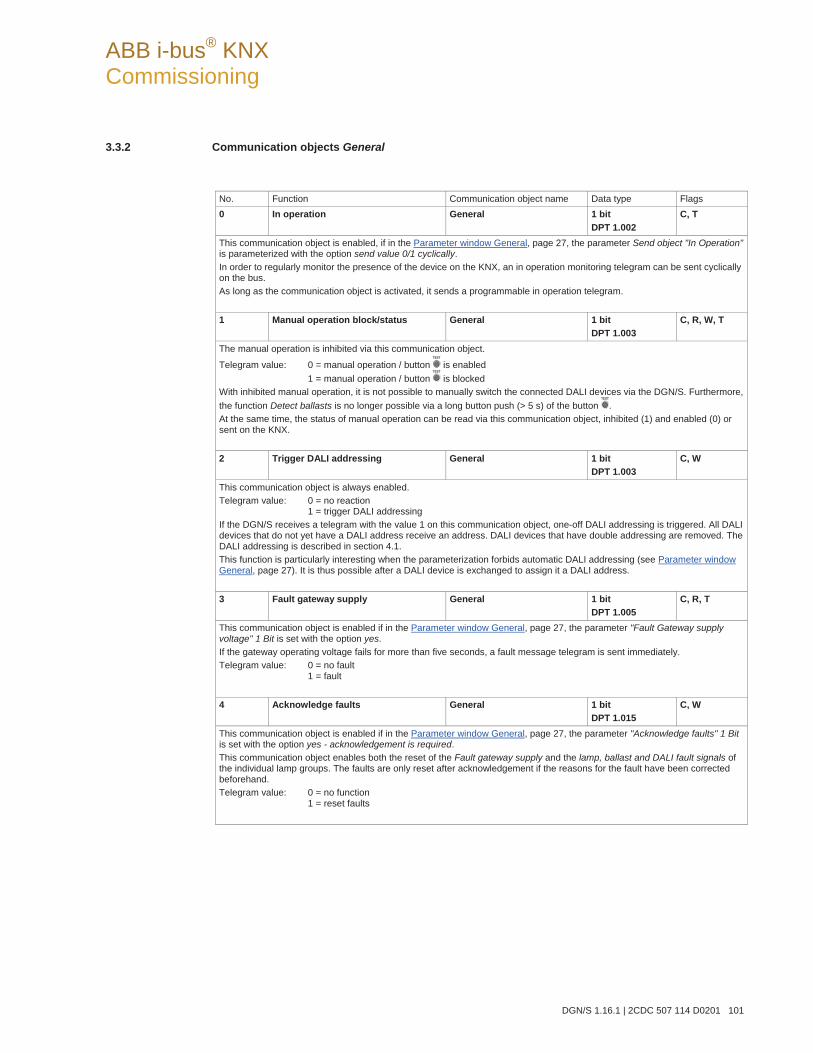
ABB i-bus® KNX Commissioning
DGN/S 1.16.1 | 2CDC 507 114 D0201 101
3.3.2 Communication objects General
No. Function Communication object name Data type Flags 0 In operation General 1 bit
DPT 1.002 C, T
This communication object is enabled, if in the Parameter window General, page 27, the parameter Send object "In Operation" is parameterized with the option send value 0/1 cyclically. In order to regularly monitor the presence of the device on the KNX, an in operation monitoring telegram can be sent cyclically on the bus. As long as the communication object is activated, it sends a programmable in operation telegram. 1 Manual operation block/status General 1 bit
DPT 1.003 C, R, W, T
The manual operation is inhibited via this communication object.
Telegram value: 0 = manual operation / button is enabled 1 = manual operation / button is blocked
With inhibited manual operation, it is not possible to manually switch the connected DALI devices via the DGN/S. Furthermore, the function Detect ballasts is no longer possible via a long button push (> 5 s) of the button . At the same time, the status of manual operation can be read via this communication object, inhibited (1) and enabled (0) or sent on the KNX. 2 Trigger DALI addressing General 1 bit
DPT 1.003 C, W
This communication object is always enabled. Telegram value: 0 = no reaction
1 = trigger DALI addressing If the DGN/S receives a telegram with the value 1 on this communication object, one-off DALI addressing is triggered. All DALI devices that do not yet have a DALI address receive an address. DALI devices that have double addressing are removed. The DALI addressing is described in section 4.1. This function is particularly interesting when the parameterization forbids automatic DALI addressing (see Parameter window General, page 27). It is thus possible after a DALI device is exchanged to assign it a DALI address. 3 Fault gateway supply General 1 bit
DPT 1.005 C, R, T
This communication object is enabled if in the Parameter window General, page 27, the parameter "Fault Gateway supply voltage" 1 Bit is set with the option yes. If the gateway operating voltage fails for more than five seconds, a fault message telegram is sent immediately. Telegram value: 0 = no fault
1 = fault 4 Acknowledge faults General 1 bit
DPT 1.015 C, W
This communication object is enabled if in the Parameter window General, page 27, the parameter "Acknowledge faults" 1 Bit is set with the option yes - acknowledgement is required. This communication object enables both the reset of the Fault gateway supply and the lamp, ballast and DALI fault signals of the individual lamp groups. The faults are only reset after acknowledgement if the reasons for the fault have been corrected beforehand. Telegram value: 0 = no function
1 = reset faults
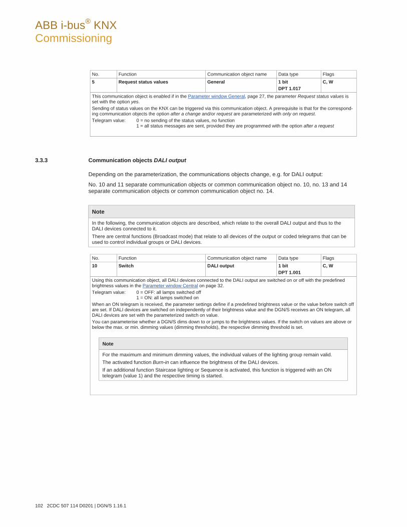
ABB i-bus® KNX Commissioning
102 2CDC 507 114 D0201 | DGN/S 1.16.1
No. Function Communication object name Data type Flags 5 Request status values General 1 bit
DPT 1.017 C, W
This communication object is enabled if in the Parameter window General, page 27, the parameter Request status values is set with the option yes. Sending of status values on the KNX can be triggered via this communication object. A prerequisite is that for the correspond-ing communication objects the option after a change and/or request are parameterized with only on request. Telegram value: 0 = no sending of the status values, no function
1 = all status messages are sent, provided they are programmed with the option after a request
3.3.3 Communication objects DALI output
Depending on the parameterization, the communications objects change, e.g. for DALI output:
No. 10 and 11 separate communication objects or common communication object no. 10, no. 13 and 14 separate communication objects or common communication object no. 14.
Note
In the following, the communication objects are described, which relate to the overall DALI output and thus to the DALI devices connected to it. There are central functions (Broadcast mode) that relate to all devices of the output or coded telegrams that can be used to control individual groups or DALI devices.
No. Function Communication object name Data type Flags 10 Switch DALI output 1 bit
DPT 1.001 C, W
Using this communication object, all DALI devices connected to the DALI output are switched on or off with the predefined brightness values in the Parameter window Central on page 32. Telegram value: 0 = OFF: all lamps switched off
1 = ON: all lamps switched on When an ON telegram is received, the parameter settings define if a predefined brightness value or the value before switch off are set. If DALI devices are switched on independently of their brightness value and the DGN/S receives an ON telegram, all DALI devices are set with the parameterized switch on value. You can parameterise whether a DGN/S dims down to or jumps to the brightness values. If the switch on values are above or below the max. or min. dimming values (dimming thresholds), the respective dimming threshold is set.
Note
For the maximum and minimum dimming values, the individual values of the lighting group remain valid. The activated function Burn-in can influence the brightness of the DALI devices. If an additional function Staircase lighting or Sequence is activated, this function is triggered with an ON telegram (value 1) and the respective timing is started.
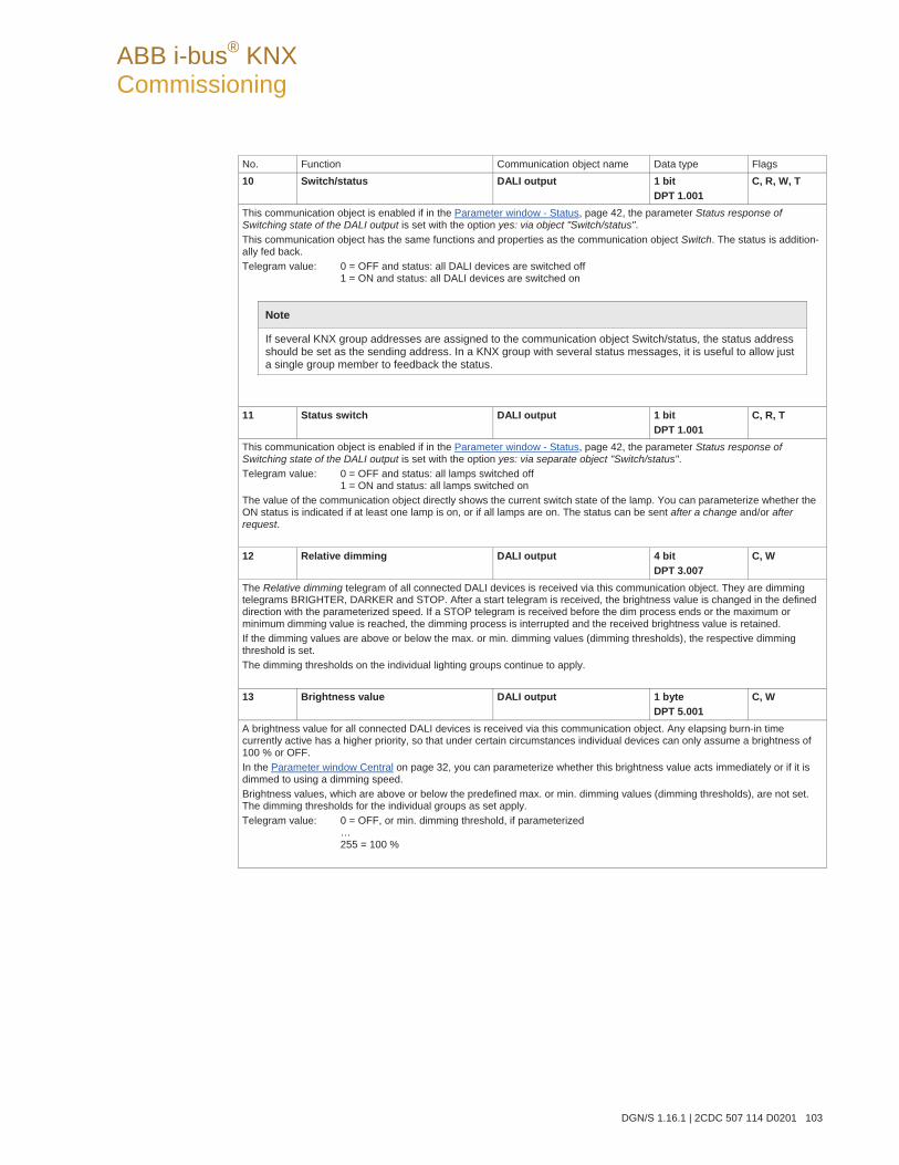
ABB i-bus® KNX Commissioning
DGN/S 1.16.1 | 2CDC 507 114 D0201 103
No. Function Communication object name Data type Flags 10 Switch/status DALI output 1 bit
DPT 1.001 C, R, W, T
This communication object is enabled if in the Parameter window - Status, page 42, the parameter Status response of Switching state of the DALI output is set with the option yes: via object "Switch/status". This communication object has the same functions and properties as the communication object Switch. The status is addition-ally fed back. Telegram value: 0 = OFF and status: all DALI devices are switched off
1 = ON and status: all DALI devices are switched on
Note
If several KNX group addresses are assigned to the communication object Switch/status, the status address should be set as the sending address. In a KNX group with several status messages, it is useful to allow just a single group member to feedback the status.
11 Status switch DALI output 1 bit
DPT 1.001 C, R, T
This communication object is enabled if in the Parameter window - Status, page 42, the parameter Status response of Switching state of the DALI output is set with the option yes: via separate object "Switch/status". Telegram value: 0 = OFF and status: all lamps switched off
1 = ON and status: all lamps switched on The value of the communication object directly shows the current switch state of the lamp. You can parameterize whether the ON status is indicated if at least one lamp is on, or if all lamps are on. The status can be sent after a change and/or after request. 12 Relative dimming DALI output 4 bit
DPT 3.007 C, W
The Relative dimming telegram of all connected DALI devices is received via this communication object. They are dimming telegrams BRIGHTER, DARKER and STOP. After a start telegram is received, the brightness value is changed in the defined direction with the parameterized speed. If a STOP telegram is received before the dim process ends or the maximum or minimum dimming value is reached, the dimming process is interrupted and the received brightness value is retained. If the dimming values are above or below the max. or min. dimming values (dimming thresholds), the respective dimming threshold is set. The dimming thresholds on the individual lighting groups continue to apply. 13 Brightness value DALI output 1 byte
DPT 5.001 C, W
A brightness value for all connected DALI devices is received via this communication object. Any elapsing burn-in time currently active has a higher priority, so that under certain circumstances individual devices can only assume a brightness of 100 % or OFF. In the Parameter window Central on page 32, you can parameterize whether this brightness value acts immediately or if it is dimmed to using a dimming speed. Brightness values, which are above or below the predefined max. or min. dimming values (dimming thresholds), are not set. The dimming thresholds for the individual groups as set apply. Telegram value: 0 = OFF, or min. dimming threshold, if parameterized
… 255 = 100 %
ABB i-bus® KNX Commissioning
104 2CDC 507 114 D0201 | DGN/S 1.16.1
No. Function Communication object name Data type Flags 13 Brightness value/status DALI output 1 byte
DPT 5.001 C, R, W, T
This communication object is enabled if in the Parameter window - Status, page 42, the parameter Status response of brightness value of the DALI output is set with the option yes: via object "Brightness value/status.This communication object has the same functions and properties as the communication object Brightness value. The status is additionally fed back. At different brightness values of the DALI devices you can parameterize whether the DGN/S indicates the smallest, the highest or the average brightness value. The parameterization is undertaken in the Parameter window -Status, page 42.
Telegram value: 0 = OFF, or minimum dimming threshold … 255 = 100 %
Note
If several groups are assigned to the communication object Brightness value/status, the status address should be set as the sending address. In a KNX group with several status messages, it is useful to allow just a single group member to feedback the status.
14 Status brightness value DALI output 1 byte
DPT 5.001 C, R, T
This communication object is enabled if in the Parameter window - Status, page 42, the parameter Status response of brightness value of the DALI output is set with the option yes: via separate object "Status brightness value". Telegram value: 0 = OFF
… 255 = 100 %, max. brightness value
This communication object reports the current brightness value of the DALI device. At different brightness values of the DALI devices you can parameterize whether the DGN/S indicates the lowest, the highest or the average brightness value. The value of the communication object updates itself during a scene dimming process or sequence. It is possible to parameterize if the status is sent on after a change and/or after request.
ABB i-bus® KNX Commissioning
DGN/S 1.16.1 | 2CDC 507 114 D0201 105
No. Function Communication object name Data type Flags 15 Status switch coded DALI output 2 byte
non DPT C, R, T
This communication object is enabled if in the Parameter window - Status, page 42, the parameter coded switch status response of a device is parameterized with the option yes.
This communication object consists of two bytes The high byte contains the switch status of the corresponding device or group. The low byte contains the device or group number, the information of whether a device or a group is selected and the information of whether it is a status request or a sent status.
High byte Low byte The hexadecimal representation is received for example, if you select the DTP 7.001 2 octet unsigned. This setting is set via the properties (select communication object, press right mouse button) as a data type. The following numbering applies for the following list: High byte Low byte
The bit number is identical with the exponent of the bit, e.g. number 2 complies with 22. Bit 0…5 corresponds with the device address (0…63) or the number of the lighting group (0…15). Bit 6 (26) determines whether the status value relates to a group (value 1) or an individual device (value 0). Bit 7 1 = Status request. If a telegram with a set bit 7 is received, it is interpreted as a status request and the
switch status of the requested group or device is sent. When the answer is sent, the value of bit 7 is reset to 0.
Bit 8 reports the switch status: 1 = lamp(s) switched on, 0 = lamp(s) switched off. Bit 9…15 value = 0 with a status feedback. These bits are not evaluated with a request (bit 7 = 1).
215 214 213 211 212 210 29 28 27 26 25 2324 22 21 20
ABB i-bus® KNX Commissioning
106 2CDC 507 114 D0201 | DGN/S 1.16.1
No. Function Communication object name Data type Flags 16 Status brightness value coded DALI output 2 byte
non DPT C, R, T
This communication object is enabled if in Parameter window - Status, page 42, the parameter Coded brightness status response of a device is parameterized with the option yes. This communication object consists of two bytes. The high byte contains the brightness value of the corresponding device or group. The low byte contains the device or group number, the brightness value and the information of whether it is a status request or a sent status.
High byte Low byte The hexadecimal representation is received for example, if you select the DTP 7.001 2 octet unsigned. This setting is set via the properties (select communication object, press right mouse button) as a data type. The following numbering applies for the following list: High byte Low byte
The bit number is identical with the exponent of the bit, e.g. number 2 complies with 22. Bit 0…5 corresponds with the device address (0…63) or the number of the lighting group (0…15). Bit 6 (26) determines whether the status value relates to a group (value 1) or an individual device (value 0). Bit 7 1 = Status request. If a telegram with a set bit 7 is received, it is interpreted as a status request and the
switch status of the requested group or device is sent. When the answer is sent, the value of bit 7 is reset to 0.
Bit 8…15 contains the brightness value of the selected lighting group or individual device as a value between 0 and 255.
17 Fault lamp DALI output 1 bit
DPT 1.005 C, R, T
This communication object is enabled if in Parameter window - Status, page 42, the parameter "Fault lamp" 1 Bit is set with the option yes. Using this communication object, a lamp fault can be sent or read. Telegram value 1 = lamp fault (at least one connected DALI device has sent a lamp fault)
0 = no lamp fault
Note
This function must be supported by the DALI devices. If DALI devices are used, which do not monitor their lighting equipment and which thus do not provide this information on the DALI, the DGN/S will also be unable to detect a lamp fault. In order to monitor a lamp fault, the function Detect ballasts does not need to be explicitly activated. In most cases, a lamp fault is only determined or indicated by the DGN/S when the lighting equipment should be switched on. For this reason, the DGN/S cannot report a fault beforehand.
Using the communication object Fault lamp (Group x), the state of the lamps for every lighting group can be indicated. Using the communication object (Diagnostics, no. 25), it is possible to request the lamp state for each DALI device.
215 214 213 211 212 210 29 28 27 26 25 2324 22 21 20
ABB i-bus® KNX Commissioning
DGN/S 1.16.1 | 2CDC 507 114 D0201 107
No. Function Communication object name Data type Flags 18 Fault ballast DALI output 1 bit
DPT 1.005 C, R, T
This communication object is enabled if in the Parameter window - Status, page 42, the parameter "Fault ballast" 1 Bit is set with the option yes. Using this communication object, a ballast fault can be sent or read. Telegram value 1 = ballast fault (at least one connected ballast has a fault)
0 = no ballast fault
A ballast fault can occur in one of the following situations: The ballast malfunctions and does not send telegrams on the DALI control line. The ballast has no ballast operating voltage and does not send telegrams on the DALI control line. The DALI control line to the ballast is interrupted, so that the DGN/S does not receive a ballast status response. The ballast has lost its address, a query from the DGN/S remains unanswered.
Note
In order to guarantee correct evaluation of a ballast fault, the DGN/S has to know how many ballasts are to be monitored. This is implemented by one-time activation of the communication object Detect ballasts (no. 28). Using this function, the DGN/S independently determines which ballasts (DALI devices / DALI addresses) are connected and uses this state as a reference value. Here not only the number but also the address of the DALI device is registered. If this system has to be modified, the option Detect ballasts should be activated. The process does not need to be repeated when exchanging a DALI device with the same address. The new DALI device receives the old DALI address and assumes the position of the DALI device it replaced. The function Detect ballasts can be triggered not only via the communication object Detect ballasts but also manu-ally by pressing the button for more than five seconds. Furthermore, this function can be triggered with the DALI-Software-Tool via button Detect ballasts in the window Options.
19 Fault DALI DALI output 1 bit
DPT 1.005 C, R, T
This communication object is enabled if in the Parameter window - Status, page 42, the parameter "Fault DALI" 1 Bit is set with the option yes. Using this communication object, a DALI fault can be sent or read. There is a DALI fault if the short circuit persists for more than 500 ms. Telegram value: 1 = DALI fault of the DALI communication
0 = no DALI fault
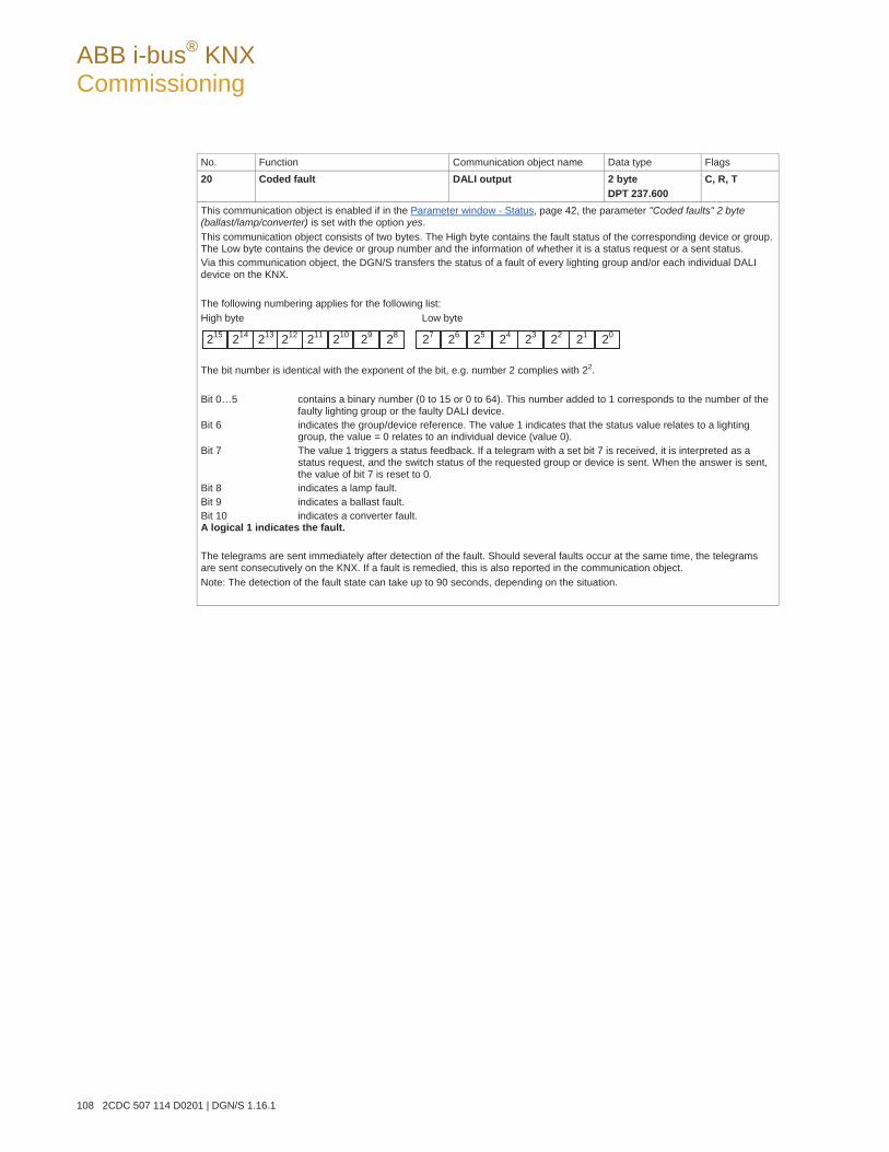
ABB i-bus® KNX Commissioning
108 2CDC 507 114 D0201 | DGN/S 1.16.1
No. Function Communication object name Data type Flags 20 Coded fault DALI output 2 byte
DPT 237.600 C, R, T
This communication object is enabled if in the Parameter window - Status, page 42, the parameter "Coded faults" 2 byte (ballast/lamp/converter) is set with the option yes. This communication object consists of two bytes. The High byte contains the fault status of the corresponding device or group. The Low byte contains the device or group number and the information of whether it is a status request or a sent status. Via this communication object, the DGN/S transfers the status of a fault of every lighting group and/or each individual DALI device on the KNX. The following numbering applies for the following list: High byte Low byte
The bit number is identical with the exponent of the bit, e.g. number 2 complies with 22. Bit 0…5 contains a binary number (0 to 15 or 0 to 64). This number added to 1 corresponds to the number of the
faulty lighting group or the faulty DALI device. Bit 6 indicates the group/device reference. The value 1 indicates that the status value relates to a lighting
group, the value = 0 relates to an individual device (value 0). Bit 7 The value 1 triggers a status feedback. If a telegram with a set bit 7 is received, it is interpreted as a
status request, and the switch status of the requested group or device is sent. When the answer is sent, the value of bit 7 is reset to 0.
Bit 8 indicates a lamp fault. Bit 9 indicates a ballast fault. Bit 10 indicates a converter fault. A logical 1 indicates the fault. The telegrams are sent immediately after detection of the fault. Should several faults occur at the same time, the telegrams are sent consecutively on the KNX. If a fault is remedied, this is also reported in the communication object. Note: The detection of the fault state can take up to 90 seconds, depending on the situation.
215 214 213 211 212 210 29 28 27 26 25 2324 22 21 20
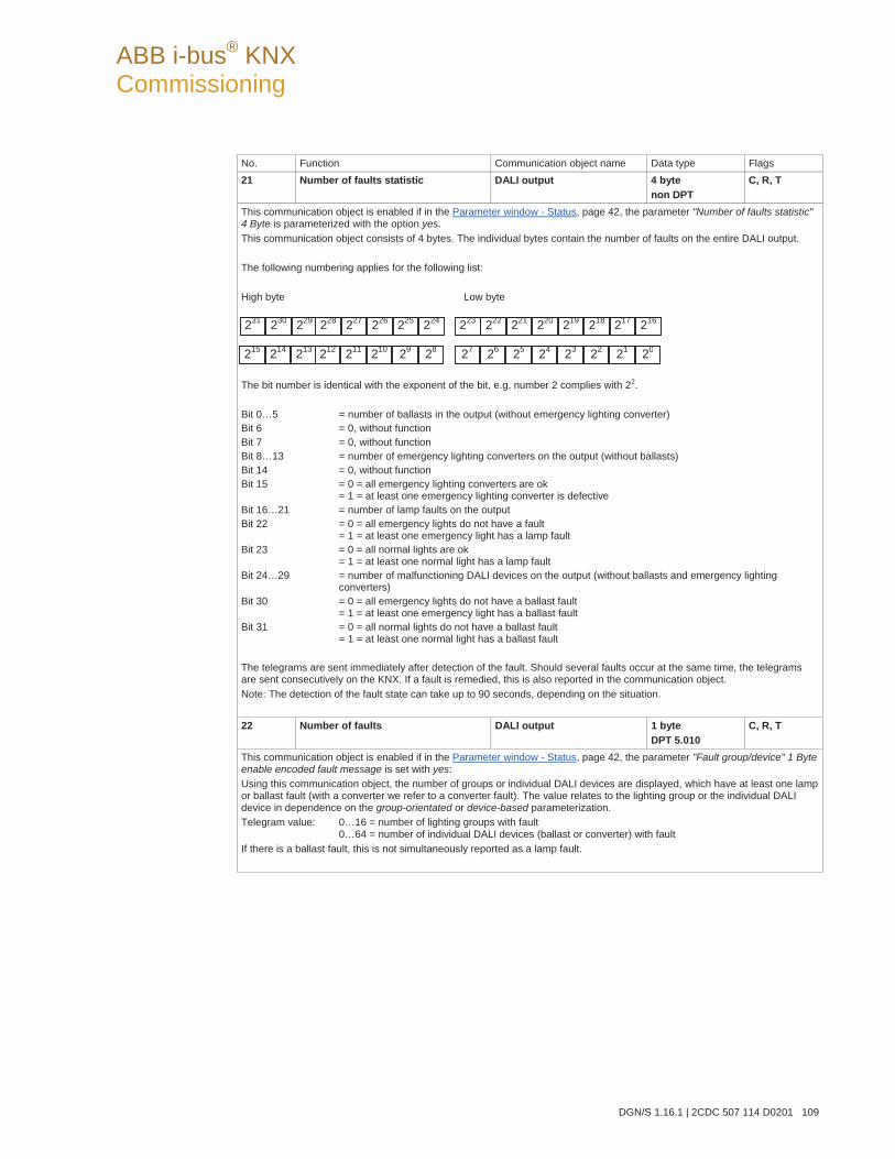
ABB i-bus® KNX Commissioning
DGN/S 1.16.1 | 2CDC 507 114 D0201 109
No. Function Communication object name Data type Flags 21 Number of faults statistic DALI output 4 byte
non DPT C, R, T
This communication object is enabled if in the Parameter window - Status, page 42, the parameter "Number of faults statistic" 4 Byte is parameterized with the option yes. This communication object consists of 4 bytes. The individual bytes contain the number of faults on the entire DALI output. The following numbering applies for the following list: High byte Low byte
The bit number is identical with the exponent of the bit, e.g. number 2 complies with 22. Bit 0…5 = number of ballasts in the output (without emergency lighting converter) Bit 6 = 0, without function Bit 7 = 0, without function Bit 8…13 = number of emergency lighting converters on the output (without ballasts) Bit 14 = 0, without function Bit 15 = 0 = all emergency lighting converters are ok
= 1 = at least one emergency lighting converter is defective Bit 16…21 = number of lamp faults on the output Bit 22 = 0 = all emergency lights do not have a fault
= 1 = at least one emergency light has a lamp fault Bit 23 = 0 = all normal lights are ok
= 1 = at least one normal light has a lamp fault Bit 24…29 = number of malfunctioning DALI devices on the output (without ballasts and emergency lighting
converters) Bit 30 = 0 = all emergency lights do not have a ballast fault
= 1 = at least one emergency light has a ballast fault Bit 31 = 0 = all normal lights do not have a ballast fault
= 1 = at least one normal light has a ballast fault The telegrams are sent immediately after detection of the fault. Should several faults occur at the same time, the telegrams are sent consecutively on the KNX. If a fault is remedied, this is also reported in the communication object. Note: The detection of the fault state can take up to 90 seconds, depending on the situation. 22 Number of faults DALI output 1 byte
DPT 5.010 C, R, T
This communication object is enabled if in the Parameter window - Status, page 42, the parameter "Fault group/device" 1 Byte enable encoded fault message is set with yes: Using this communication object, the number of groups or individual DALI devices are displayed, which have at least one lamp or ballast fault (with a converter we refer to a converter fault). The value relates to the lighting group or the individual DALI device in dependence on the group-orientated or device-based parameterization. Telegram value: 0…16 = number of lighting groups with fault
0…64 = number of individual DALI devices (ballast or converter) with fault If there is a ballast fault, this is not simultaneously reported as a lamp fault.
215 214 213 211 212 210 29 28 27 26 25 2324 22 21 20
231 230 229 227 228 226 225 224 223 222 221 219220 218 217 216
ABB i-bus® KNX Commissioning
110 2CDC 507 114 D0201 | DGN/S 1.16.1
No. Function Communication object name Data type Flags 23 Fault group/device DALI output 1 byte
DPT 5.010 C, R, T
This communication object is enabled if in Parameter window - Status, page 42, the parameter "Fault group/device" 1 Byte enable encoded fault message is set with the option yes. With this communication object, the first lighting group or the first DALI device (ballast or converter) is displayed as a figure value. The value relates directly to the lighting group or the individual DALI device in dependence on the group-orientated or device-based parameterization. A correction by 1 as required for the values in the communication object Diagnostics (no. 25) is not necessary in the communication object described here. Telegram value: 1…16 = number of lighting group with fault
1…64 = number of individual DALI device with fault All lighting groups or DALI devices with a fault can be displayed successively in conjunction with the communication object Switch up next fault alarm (no. 24). If the communication group Number of faults is added, you can recognise how often you will need to switch up in order to view all faults. 24 Switch up next fault alarm DALI output 1 byte
DPT 1.008 C, W
This communication object is enabled if in Parameter window - Status, page 42, the parameter "Fault group/device" 1 Byte enable encoded fault message is set with yes. This communication object should be considered in conjunction with the communication object No. Group/device fault (No. 23). Should there be several group or device faults, this communication object can be used to switch to the next number of the communication object Fault group/device. With the value 0, you can advance by a number, and with the value 1 you can go back by a number. Telegram value: 0 = “switch up”: The next higher number of lighting group or DALI device with a fault is displayed on the
communication object Fault group/device (no. 23). 1 = “switch down”: The next lower number of lighting group or DALI device with a fault is displayed on the communication object Fault group/device (no. 23).
If the highest number is encountered during switch up or the lowest number is encountered during switching down, the switching up or down telegram will not switch further up or down.
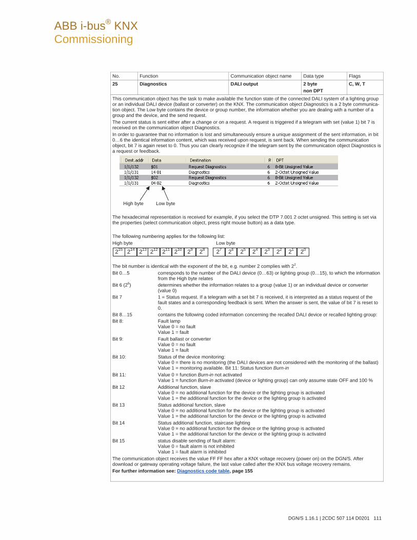
ABB i-bus® KNX Commissioning
DGN/S 1.16.1 | 2CDC 507 114 D0201 111
No. Function Communication object name Data type Flags 25 Diagnostics DALI output 2 byte
non DPT C, W, T
This communication object has the task to make available the function state of the connected DALI system of a lighting group or an individual DALI device (ballast or converter) on the KNX. The communication object Diagnostics is a 2 byte communica-tion object. The Low byte contains the device or group number, the information whether you are dealing with a number of a group and the device, and the send request. The current status is sent either after a change or on a request. A request is triggered if a telegram with set (value 1) bit 7 is received on the communication object Diagnostics. In order to guarantee that no information is lost and simultaneously ensure a unique assignment of the sent information, in bit 0…6 the identical information content, which was received upon request, is sent back. When sending the communication object, bit 7 is again reset to 0. Thus you can clearly recognize if the telegram sent by the communication object Diagnostics is a request or feedback.
High byte Low byte The hexadecimal representation is received for example, if you select the DTP 7.001 2 octet unsigned. This setting is set via the properties (select communication object, press right mouse button) as a data type. The following numbering applies for the following list: High byte Low byte
The bit number is identical with the exponent of the bit, e.g. number 2 complies with 22. Bit 0…5 corresponds to the number of the DALI device (0…63) or lighting group (0…15), to which the information
from the High byte relates Bit 6 (26) determines whether the information relates to a group (value 1) or an individual device or converter
(value 0) Bit 7 1 = Status request. If a telegram with a set bit 7 is received, it is interpreted as a status request of the
fault states and a corresponding feedback is sent. When the answer is sent, the value of bit 7 is reset to 0.
Bit 8…15 contains the following coded information concerning the recalled DALI device or recalled lighting group: Bit 8: Fault lamp
Value 0 = no fault Value 1 = fault
Bit 9: Fault ballast or converter Value 0 = no fault Value 1 = fault
Bit 10: Status of the device monitoring: Value 0 = there is no monitoring (the DALI devices are not considered with the monitoring of the ballast) Value 1 = monitoring available. Bit 11: Status function Burn-in
Bit 11: Value 0 = function Burn-in not activated Value 1 = function Burn-in activated (device or lighting group) can only assume state OFF and 100 %
Bit 12 Additional function, slave Value 0 = no additional function for the device or the lighting group is activatedValue 1 = the additional function for the device or the lighting group is activated
Bit 13 Status additional function, slave Value 0 = no additional function for the device or the lighting group is activatedValue 1 = the additional function for the device or the lighting group is activated
Bit 14 Status additional function, staircase lighting Value 0 = no additional function for the device or the lighting group is activatedValue 1 = the additional function for the device or the lighting group is activated
Bit 15 status disable sending of fault alarm: Value 0 = fault alarm is not inhibited Value 1 = fault alarm is inhibited
The communication object receives the value FF FF hex after a KNX voltage recovery (power on) on the DGN/S. After download or gateway operating voltage failure, the last value called after the KNX bus voltage recovery remains. For further information see: Diagnostics code table, page 155
215 214 213 211 212 210 29 28 27 26 25 2324 22 21 20
ABB i-bus® KNX Commissioning
112 2CDC 507 114 D0201 | DGN/S 1.16.1
No. Function Communication object name Data type Flags 26 Dimming to basis brightness DALI output 1 bit
DPT 1.003 C, W
With this communication object, it is possible to disable the fault messages (lamp, ballast and converter fault) of the DGN/S. If the fault messages are inhibited, the DGN/S will continue to undertake fault message examination regarding lamp, ballast and converter faults. During the inhibit, the faults are evaluated but not sent on the KNX. The values of the communication objects are also not updated. The latent time of the system can be minimized at low KNX load when the fault messages are inhibited. When all error messages are enabled, the malfunctions will be sent in accordance with their parameterization. If a fault still exists after enabling of the error message, this fault is recorded and the information is sent on the KNX in accordance with the parameterization. Telegram value: 1 = disabling of fault messages (lamp, ballast and converter fault)
0 = enabling of fault messages (lamp, ballast and converter fault)
Note
This function can, for example, be useful for systems with emergency lighting applications for daily checking of the lamps of the DALI devices by the DALI control line and thus disconnect them from the DALI master (DGN/S). In this case, the DGN/S detects the loss of the DALI device and sends a ballast fault even though this is a normal operating state. Should the fault message be disabled before separation from the DALI control line, no fault is reported on the DGN/S. Operation can continue as normal. After checking the lighting equipment, normal monitoring can be reactivated via the error message communication object Disable sending of fault alarm.
27 Flexible time DALI output 1 byte
Non DTP C, W
This communication object is always enabled. Using this communication object, with the appropriate parameterization the various dimming times can be modified via KNX. The flexible time does not relate to central telegrams but rather exclusively to group or scene telegrams. There is only one flexible dimming time per Gateway that acts on all parameterized flexible dimming times. Dimming time for switch on and off value Dimming time for brightness values Dimming time for relative dimming (dimming speed) Dimming time for slave brightness values Staircase lighting time Time duration of the basis brightness for staircase lighting Transition time in sequence operation
Telegram value: 0 to 65,535 in s Flexible time is used directly after download. If no flexible time is used before the value is 0 s. The communication object value is set by the parameterized value after bus voltage recovery. A value set via the bus before-hand is overwritten and is lost.
ABB i-bus® KNX Commissioning
DGN/S 1.16.1 | 2CDC 507 114 D0201 113
No. Function Communication object name Data type Flags 28 Detect ballasts DALI output 1 bit
DPT 1.010 C, W
Using this communication object, the current state for the DGN/S can be stored as the reference state. In order to correctly detect a ballast fault, the DGN/S must have correctly identified all connected DALI devices and thus know the number of connected DALI devices to be monitored. This identification process runs autonomously and fully automatically in the background, after the DGN/S has received a detection telegram with value 1 via this communication object. The DGN/S notes the current system configuration as a reference state. For this purpose, all DALI addresses are stored in the DGN/S. Should a DALI address now be lost, e.g. by a ballast fault, cable break, etc., this is interpreted by the DGN/S as a ballast fault and sent on the KNX as set in the parameterization. An automatic detection, e.g. after a KNX voltage recovery or Gateway operating voltage recovery, does not take place. The detection should be carried out directly after commissioning or when extending or reducing the DALI devices. The DALI devices are continually monitored, regardless of whether the lamp is activated or deactivated. The DALI devices must be installed properly and supplied with operating voltage if necessary. Telegram value 1 = start DALI device detection procedure
0 = no function
Note
This function can be manually triggered if the button on the DGN/S device is pushed for longer than five seconds. Furthermore, the detection of DALI devices and saving as a reference value is possible in the DALI-Software-Tool via the button Detect ballasts.
29 Burn-in lamps
Burn-in lamps/status DALI output 1 bit
DPT 1.010 C, W
This communication object is enabled if in Parameter window Central, page 32, the parameter Enable function lamp Burn-in object "Burn-in lamps" 1 Bit is set with the option yes. Using this communication object, the function Burn in is activated or deactivated for protecting the ballast and the lamp. After receiving a telegram with the value 1, all lighting groups intended for burn-in can only be controlled with 0 % (OFF) or 100 % brightness. Whether a lighting group is considered during burn-in is set in the Parameter window Gx Group, page 51, with the parameter Enable with burn-in function (Object "Burn-In lamps"). Incoming telegrams have an effect on all lighting groups which are intended for burn-in purposes. The time duration for burn-in is defined commonly for all lighting groups. After this burn-in time has elapsed, the lighting group can be dimmed as usual, and the programmed light scene can be recalled. If a telegram with the value 1 is received on the communication object Burn-In lamps during the burn-in time, the period restarts from the beginning. A telegram with the value 0 deactivates the function Burn-in and enables “normal” operation. The burn-in time is only counted if a ballast on the DALI output is connected and supplied with power. The burn-in time counts in five minute steps. Telegram value: 1 = activate functions
0 = deactivate functions For further information see: Burning-in of luminaries, page 133
Simulation of DALI values running in background. It will be set with end of burn-in.
ABB i-bus® KNX Commissioning
114 2CDC 507 114 D0201 | DGN/S 1.16.1
No. Function Communication object name Data type Flags 30 Remaining burn-in time (coded) DALI output 3 byte
non DPT C, R, T
This communication object is enabled if in Parameter window Central, page 32, the parameter Status of remaining burn-in time (coded) is set with the option yes. This communication object consists of three bytes. The two High bytes contains the remaining burn-in time, for which the device is in burn-in mode. The Low byte (address-Byte) contains the devices and the information of whether it is a status request or a sent status. The following numbering applies for the following list: High byte
Low byte (address-Byte) The bit number is identical with the exponent of the bit, e.g. number 2 complies with 22. Bit 0…5 = contains a binary number (0 to 15 or 0 to 64). This number corresponds to 1 added, to the number of
the DALI device to which the information in the high byte is related. Bit 6 = 0 determines status value relates to an individual DALI device . Bit 7 = 1 Status request. If a telegram with a set bit 7 is received, it is interpreted as a status request of the
remaining burn-in time and a corresponding feedback is sent. When the answer is sent, the value of bit 7 is reset to 0.
Bit 8…23 = The figure value (DTP 7.007) corresponds to the remaining burn-in time in hours of the low byte set in the DALI device.
31 Emergency test trigger DALI output 2 byte
non DPT C, W, T
This communication object is always enabled and is used for triggering an emergency test.. This communication object consists of two bytes. The high byte receives the emergency lighting test that is to be started in coded form. The low byte contains the number of the device. The response of emergency test result is send via communica-tion object Emergency test status (No. 32). The following numbering applies for the following list: High byte Low byte
The bit number is identical with the exponent of the bit, e.g. number 2 complies with 22. Bit 0…5 = contains the binary number (0…63). This number corresponds to 1 added to the number of the DALI
device, to which the information in the high byte is related Bit 6 (26) = 0 determines status value relates to an individual device (converter). Bit 7 = 1 Status request. If a telegram with a set bit 7 is received, it is interpreted as a status request and the
status of the requested device is sent. When the answer is sent, the value of bit 7 is reset to 0. Bit 8 and 10 = 000, stops the tests currently in operation
= 001, function test is triggered = 010, partial duration test is triggered = 011, duration test is triggered = 100, battery request triggered = 101, 110 and 111 without function or the evaluation of the request is not considered
Bit 11…15 = 0 without function or the evaluation of the request is not considered. Note: For the response of emergency test result can also be use the addressable communication object Emergency test result (No. 33) or the communication object Emergency test trigger/status (no 168) per emergency converter.
223 222 221 219 220 218 217 216 215 214 213 211 212 210 29 28
215 214 213 211 212 210 29 28 27 26 25 23 24 22 21 20
27 26 25 23 24 22 21 20
ABB i-bus® KNX Commissioning
DGN/S 1.16.1 | 2CDC 507 114 D0201 115
No. Function Communication object name Data type Flags 32 Emergency test status DALI output 2 byte
non DPT C, R, T
This communication object is enabled if in Parameter window - Emergency, page 39, the parameter Emergency test status is set with the option yes. This communication object consists of two bytes. The high byte receives in coded form the current testing state of the emergency converter specified in the low byte. The automatically status response will only send back for the selected emergency converter. The emergency test themselves is triggered e.g. via the addressable communication object Emergency test result (No. 33) or the communication object Emer-gency test trigger/status (no 168) per emergency converter. The following numbering applies for the following list: High byte Low byte
The bit number is identical with the exponent of the bit, e.g. number 2 complies with 22. Bit 0…5 = contains the binary number (0…63). This number corresponds to 1 added, to the number of the DALI
device to which the information in the High byte is related Bit 6 = 0 determines status value relates to an individual device (converter). Bit 7 = 1, status value request. If a telegram with a set bit 7 is received, it is interpreted as a status request of
the testing state and a corresponding feedback is sent. When the answer is sent, the value of bit 7 is re-set to 0
Bit 8 and 10 = 000, no testing = 001, functional test = 010, partial duration test = 011, duration test = 100, battery request runs (does not require any time, and is not displayed for this reason) = 101 and 110 without function or the evaluation of the request is not considered = 111 It is no valid test status available or the DALI member do not support DALI emergency converter according IEC 6286-202. The content of Bits 8 to 15 are invalid..
Bit 11 and 12 = 00, testing has ended positively = 01, testing pending, not yet started = 10, test runs = 11, test interrupted
Bit 13 = 1, testing manually started Bit 14 = 1, lamp fault (converter) Bit 15 = 1, device (ballast/converter) fault
Bit 14 and 15 show the status of an emergency converter. For a normal DALI device bit 6 and 7 are not calculated. For a normal lamp or ballast failure group communication object no. 45 and coded communication object no. 20 are available.
215 214 213 211 212 210 29 28 27 26 25 23 24 22 21 20
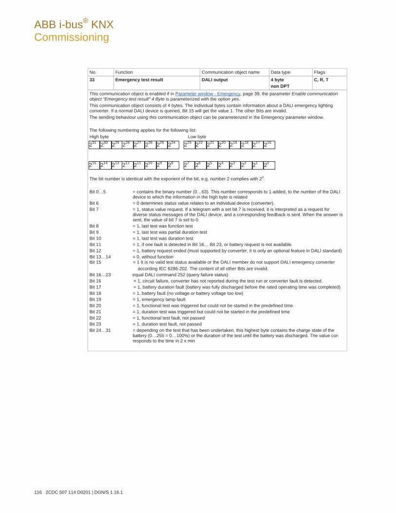
ABB i-bus® KNX Commissioning
116 2CDC 507 114 D0201 | DGN/S 1.16.1
No. Function Communication object name Data type Flags 33 Emergency test result DALI output 4 byte
non DPT C, R, T
This communication object is enabled if in Parameter window - Emergency, page 39, the parameter Enable communication object "Emergency test result" 4 Byte is parameterized with the option yes. This communication object consists of 4 bytes. The individual bytes contain information about a DALI emergency lighting converter. If a normal DALI device is queried, Bit 15 will get the value 1. The other Bits are invalid. The sending behaviour using this communication object can be parameterized in the Emergency parameter window. The following numbering applies for the following list: High byte Low byte
The bit number is identical with the exponent of the bit, e.g. number 2 complies with 22. Bit 0…5 = contains the binary number (0…63). This number corresponds to 1 added, to the number of the DALI
device to which the information in the high byte is related Bit 6 = 0 determines status value relates to an individual device (converter). Bit 7 = 1, status value request. If a telegram with a set bit 7 is received, it is interpreted as a request for
diverse status messages of the DALI device, and a corresponding feedback is sent. When the answer is sent, the value of bit 7 is set to 0
Bit 8 = 1, last test was function test Bit 9 = 1, last test was partial duration test Bit 10 = 1, last test was duration test Bit 11 = 1, if one fault is detected in Bit 16… Bit 23, or battery request is not available. Bit 12 = 1, battery request ended (must supported by converter, it is only an optional feature in DALI standard) Bit 13…14 = 0, without function Bit 15 = 1 It is no valid test status available or the DALI member do not support DALI emergency converter according IEC 6286-202. The content of all other Bits are invalid. Bit 16…23 equal DALI command 252 (query failure status) Bit 16 = 1, circuit failure, converter has not reported during the test run or converter fault is detected. Bit 17 = 1, battery duration fault (battery was fully discharged before the rated operating time was completed) Bit 18 = 1, battery fault (no voltage or battery voltage too low) Bit 19 = 1, emergency lamp fault Bit 20 = 1, functional test was triggered but could not be started in the predefined time Bit 21 = 1, duration test was triggered but could not be started in the predefined time Bit 22 = 1, functional test fault, not passed Bit 23 = 1, duration test fault, not passed Bit 24…31 = depending on the test that has been undertaken, this highest byte contains the charge state of the
battery (0…255 = 0…100%) or the duration of the test until the battery was discharged. The value cor-responds to the time in 2 x min
215 214 213 211 212 210 29 28 27 26 25 23 24 22 21 20
231 230 229 227 228 226 225 224 223 222 221 219 220 218 217 216
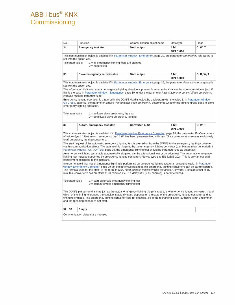
ABB i-bus® KNX Commissioning
DGN/S 1.16.1 | 2CDC 507 114 D0201 117
No. Function Communication object name Data type Flags 34 Emergency test stop DALI output 1 bit
DPT 1.010 C, W, T
This communication object is enabled if in Parameter window - Emergency, page 39, the parameter Emergency test status is set with the option yes. Telegram value: 1 = all emergency lighting tests are stopped.
0 = no function 35 Slave emergency active/status DALI output 1 bit
DPT 1.010 C, R, W, T
This communication object is enabled if in Parameter window - Emergency, page 39, the parameter Pass slave emergency is set with the option yes. The information indicating that an emergency lighting situation is present is sent on the KNX via this communication object. If this is the case in Parameter window - Emergency, page 39, under the parameter Pass slave emergency / Slave emergency criterion must be parameterized. Emergency lighting operation is triggered in the DGN/S via this object by a telegram with the value 1. In Parameter windowGx Group, page 51, the parameter Enable with function slave emergency determines whether the lighting group goes to slave emergency lighting operation. Telegram value 1 = activate slave emergency lighting
0 = deactivate slave emergency lighting 36 Autom. emergency test start Converter 1...64 1 bit
DPT 1.010 C, W, T
This communication object is enabled, if in Parameter window Emergency Converter, page 90, the parameter Enable commu-nication object: "Start autom. emergency test" 1 Bit has been parameterized with yes. This communication relates exclusively to all emergency lighting converters. The start request of the automatic emergency lighting test is passed on from the DGN/S to the emergency lighting converter via this communication object. The start itself is triggered by the emergency lighting converter (e.g. battery must be loaded). In Parameter window - Cx…Cy Test, page 95, the emergency lighting test should be parameterized as automatic. An emergency lighting test that is automatically triggered can be a functional test or duration test. The automatic emergency lighting test must be supported by emergency lighting converters (device type 1 to EN 62386-202). This is only an optional requirement according to the standard. In order to avoid that not all emergency lighting is performing an emergency lighting test or a recharging cycle, in Parameter window Emergency Converter, page 90, an offset for two neighbouring emergency lighting converters can be parameterized. The formula used for the offset is the formula DALI short address multiplied with the offset. Converter 1 has an offset of 15 minutes, converter 2 has an offset of 30 minutes etc., if a delay of 1 (= 15 minutes) is parameterized. Telegram value 1 = start automatic emergency lighting test
0 = stop automatic emergency lighting test The DGN/S passes on this time just as the actual emergency lighting trigger signal to the emergency lighting converter. If and which of the timing tolerances the conditions actually start, depends on the state of the emergency lighting converter and its timing tolerances. The emergency lighting converter can, for example, be in the recharging cycle (20 hours is not uncommon) and the (pending) test does not start. 37…39 Empty
Communication objects are not used
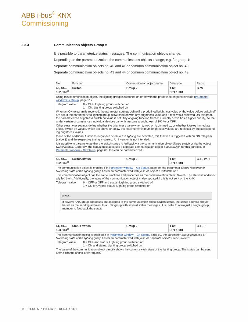
ABB i-bus® KNX Commissioning
118 2CDC 507 114 D0201 | DGN/S 1.16.1
3.3.4 Communication objects Group x
It is possible to parameterize status messages. The communication objects change.
Depending on the parameterization, the communications objects change, e.g. for group 1:
Separate communication objects no. 40 and 41 or common communication object no. 40.
Separate communication objects no. 43 and 44 or common communication object no. 43.
No. Function Communication object name Data type Flags 40, 48… 152, 1601)
Switch Group x 1 bit DPT 1.001
C, W
Using this communication object, the lighting group is switched on or off with the predefined brightness value (Parameterwindow Gx Group, page 51). Telegram value: 0 = OFF: Lighting group switched off
1 = ON: Lighting group switched on When an ON telegram is received, the parameter settings define if a predefined brightness value or the value before switch off are set. If the parameterized lighting group is switched on with any brightness value and it receives a renewed ON telegram, the parameterized brightness switch on value is set. Any ongoing function Burn-in currently active has a higher priority, so that under certain circumstances individual devices can only assume a brightness of 100 % or OFF. Other parameter settings define whether the brightness value when turned on is dimmed to, or whether it takes immediate effect. Switch on values, which are above or below the maximum/minimum brightness values, are replaced by the correspond-ing brightness values. If one of the additional functions Sequence or Staircase lighting are activated, this function is triggered with an ON telegram (value 1) and the respective timing is started. An inversion is not intended. It is possible to parameterize that the switch status is fed back via the communication object Status switch or via the object Switch/status. Generally, the status messages use a separate communication object Status switch for this purpose. In Parameter window – Gx Status, page 60, this can be parameterized. 40, 48… 152, 1601)
Switch/status Group x 1 bit DPT 1.001
C, R, W, T
The communication object is enabled if in Parameter window – Gx Status, page 60, the parameter Status response of Switching state of the lighting group has been parameterized with yes: via object "Switch/status". This communication object has the same functions and properties as the communication object Switch. The status is addition-ally fed back. Additionally, the value of the communication object is also updated if this is not sent on the KNX. Telegram value: 0 = OFF or OFF and status: Lighting group switched off
1 = ON or ON and status: Lighting group switched on
Note
If several KNX group addresses are assigned to the communication object Switch/status, the status address should be set as the sending address. In a KNX group with several status messages, it is useful to allow just a single group member to feedback the status.
41, 49… 153, 1611)
Status switch Group x 1 bit DPT 1.001
C, R, T
This communication object is enabled if in Parameter window – Gx Status, page 60, the parameter Status response of Switching state of the lighting group has been parameterized with yes: via separate object "Status switch". Telegram value: 0 = OFF and status: Lighting group switched off
1 = ON and status: Lighting group switched on The value of the communication object directly shows the current switch state of the lighting group. The status can be sent after a change and/or after request.
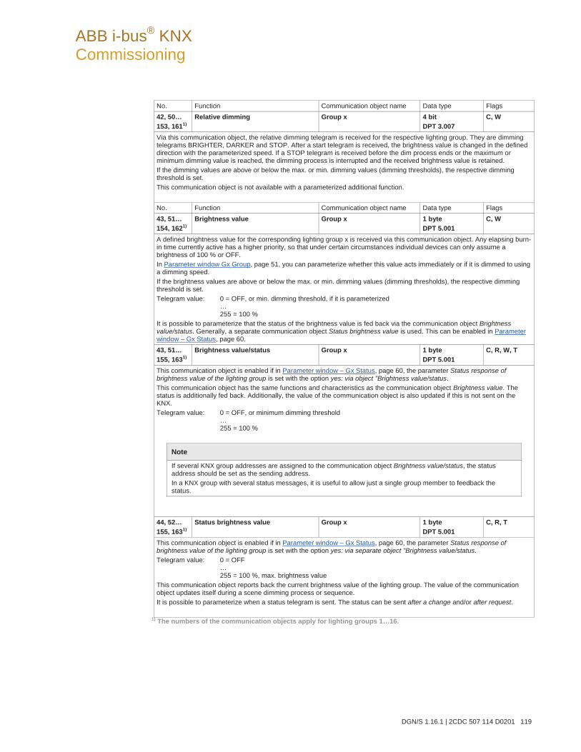
ABB i-bus® KNX Commissioning
DGN/S 1.16.1 | 2CDC 507 114 D0201 119
No. Function Communication object name Data type Flags 42, 50… 153, 1611)
Relative dimming Group x 4 bit DPT 3.007
C, W
Via this communication object, the relative dimming telegram is received for the respective lighting group. They are dimming telegrams BRIGHTER, DARKER and STOP. After a start telegram is received, the brightness value is changed in the defined direction with the parameterized speed. If a STOP telegram is received before the dim process ends or the maximum or minimum dimming value is reached, the dimming process is interrupted and the received brightness value is retained. If the dimming values are above or below the max. or min. dimming values (dimming thresholds), the respective dimming threshold is set. This communication object is not available with a parameterized additional function. No. Function Communication object name Data type Flags 43, 51… 154, 1621)
Brightness value Group x 1 byte DPT 5.001
C, W
A defined brightness value for the corresponding lighting group x is received via this communication object. Any elapsing burn-in time currently active has a higher priority, so that under certain circumstances individual devices can only assume a brightness of 100 % or OFF. In Parameter window Gx Group, page 51, you can parameterize whether this value acts immediately or if it is dimmed to using a dimming speed. If the brightness values are above or below the max. or min. dimming values (dimming thresholds), the respective dimming threshold is set. Telegram value: 0 = OFF, or min. dimming threshold, if it is parameterized
… 255 = 100 %
It is possible to parameterize that the status of the brightness value is fed back via the communication object Brightness value/status. Generally, a separate communication object Status brightness value is used. This can be enabled in Parameterwindow – Gx Status, page 60. 43, 51… 155, 1631)
Brightness value/status Group x 1 byte DPT 5.001
C, R, W, T
This communication object is enabled if in Parameter window – Gx Status, page 60, the parameter Status response of brightness value of the lighting group is set with the option yes: via object "Brightness value/status. This communication object has the same functions and characteristics as the communication object Brightness value. The status is additionally fed back. Additionally, the value of the communication object is also updated if this is not sent on the KNX. Telegram value: 0 = OFF, or minimum dimming threshold
… 255 = 100 %
Note
If several KNX group addresses are assigned to the communication object Brightness value/status, the status address should be set as the sending address. In a KNX group with several status messages, it is useful to allow just a single group member to feedback the status.
44, 52… 155, 1631)
Status brightness value Group x 1 byte DPT 5.001
C, R, T
This communication object is enabled if in Parameter window – Gx Status, page 60, the parameter Status response of brightness value of the lighting group is set with the option yes: via separate object "Brightness value/status. Telegram value: 0 = OFF
… 255 = 100 %, max. brightness value
This communication object reports back the current brightness value of the lighting group. The value of the communication object updates itself during a scene dimming process or sequence. It is possible to parameterize when a status telegram is sent. The status can be sent after a change and/or after request.
1) The numbers of the communication objects apply for lighting groups 1…16.
ABB i-bus® KNX Commissioning
120 2CDC 507 114 D0201 | DGN/S 1.16.1
3.3.5 Communication objects Fault
In addition to the control telegrams and status responses of the lighting groups, there is the possibility to set the fault status for the lighting group on the KNX via a separate communication object for every lighting group.
No. Function Communication object name Data type Flags 45, 53… 156, 1641)
Fault lamp or ballast Fault ballast Fault lamp
Group x 1 bit: DPT 1.005
C, R, T
Via this communication object, a fault can be displayed in lighting group x on the KNX via this communication object in Parameter window – Gx Status page 60. This communication object is a variable communication object, which contains, according to its parameterization, information about a ballast fault, a lamp fault or a combination of both faults. Telegram value 1 = fault of one or more DALI devices in the lighting group x
0 = no fault Ballast fault: The failure of ballast in the lighting group is displayed. Loss of a ballast can be due to one of the following situations: The ballast malfunctions and does not send telegrams on the DALI control line The ballast has no ballast operating voltage and does not send telegrams on the DALI control line The DALI control line to the ballast is interrupted so that the DGN/S does not receive a ballast status response The ballast has lost its address, a query from the DGN/S remains unanswered
Note
In order to guarantee correct evaluation of a ballast fault, the DGN/S has to know how many ballasts are to be monitored. This is implemented by one-time activation of the communication object Detect ballasts (no. 28). Using this function, the DGN/S independently determines which ballasts (DALI devices / DALI addresses) are connected and uses this state as a reference value. Here not only the number but also the address of the DALI device is registered. If the system has to be modified, the function Detect ballasts option must be activated. The process does not need to be repeated when exchanging a DALI device with the same address. The new DALI device receives the old DALI address and assumes the position of the DALI device it replaced. The function Detect ballasts, can be triggered not only via the communication object Detect ballasts but also manually by pressing the button for more than five seconds. Furthermore, this function can be triggered with the DALI-Software-Tool via button Detect ballasts in the Options window.
Lamp fault: A defective lamp in the lighting group is indicated. This function must be supported by the DALI devices. When DALI devices are used, which do not monitor their lighting equipment and which thus do not provide this information on the DALI, the DGN/S will also be unable to detect a lamp fault. In order to monitor a lamp fault, the function Detect ballasts does not need to be explicitly activated. Fault lamp or fault ballast: A fault in the lighting group is displayed if at least one lamp or ballast exhibits a fault. Both faults are logically linked in the DGN/S with a logical OR.
Note
The information about an individual DALI device is provided with a fault by the DGN/S via coded diagnostics communication objects (no. 25). Using communication object Group/device fault, the number of every faulty DALI device is sent on the KNX and requested if required.
ABB i-bus® KNX Commissioning
DGN/S 1.16.1 | 2CDC 507 114 D0201 121
No. Function Communication object name Data type Flags
46, 55… 158, 1661)
Number of faults statistic Group x 4 byte non DPT
C, R, T
This communication object is enabled, if in Parameter window – Gx Status, page 60, the parameter Status response statistic Obj. "Number of faults statistic" has been parameterized with option yes. This communication object consists of 4 bytes. The individual bytes contain information about the number of faults DALI devices in the lighting group. The sending behaviour using this communication object can be parameterized in the Parameter window – Gx Status, page 60. The following numbering applies for the following list: High byte Low byte
The bit number is identical with the exponent of the bit, e.g. number 2 complies with 22. Bit 0…5 = contains as a value the number of DALI ballasts in the lighting group Bit 6 and 7 = 0, without function Bit 8…13 = contains as a value the number of emergency lighting converters in the lighting group Bit 14 = 0, without function Bit 15 = 1, at least one emergency lighting converter in the lighting group is faulty Bit 16…21 = contains as a value the number of faulty lamps in the lighting group Bit 22 = 1, at least one lamp in the lighting group is faulty Bit 23 = 1, at least one lamp in a normal light in the lighting group is faulty Bit 24…29 = contains as a value the number of faulty DALI devices (ballasts & converters) in the lighting group Bit 30 = 1, at least one ballast of an emergency light in the lighting group is faulty Bit 31 = 1, at least one ballast of a normal light in the lighting group is faulty 47, 56… 159, 1671)
Empty
Communication objects are not used.
215 214 213 211 212 210 29 28 27 26 25 2324 22 21 20
231 230 229 227 228 226 225 224 223 222 221 219220 218 217 216
ABB i-bus® KNX Commissioning
122 2CDC 507 114 D0201 | DGN/S 1.16.1
3.3.6 Communication objects Converter x
As soon as in parameter window Cx Converter an emergency lighting test is enabled, the communication object Emergency test trigger for converter x is enabled. The following emergency lighting tests can be triggered via this communication object for the emergency lighting converter.
Function test
Partial duration test
Duration test
Battery
Explanations about the tests can be found in section 1.3.2.
Via the parameter Enable coded status emergency test in Parameter window Cx…Cy Converter, page 92, the communication object for the Emergency test trigger/status changes. Using this communication object, the result of the emergency lighting test for the emergency lighting converter is transferred on the KNX.
No. Function Communication object name Data type Flags 168 Emergency test trigger Converter x 1 byte
non DPT C, W, T
This communication object is enabled if in Parameter window Cx…Cy Converter, page 92, the parameter Emergency test trigger is set with the option yes. An emergency lighting test can be triggered via this communication object for the emergency lighting converter x. The following numbering applies for the following list:
The bit number is identical with the exponent of the bit, e.g. number 2 complies with 22. Bit 0 … 2 = 000, stops the tests currently in operation
= 001, function test is requested = 010, partial duration test is requested = 011, duration test is requested = 100, battery is requested = 101, 110 and 111 without function or the evaluation of the request is not considered
Bit 3…7 = 0 without function or the evaluation of the request is not considered. If a new test is requested on the communication object, before the ongoing test has ended, this is immediately interrupted and the new test is required. This is also the case when the ongoing test is requested again. Only one test can be undertaken on the converter at any time.
27 26 25 23 24 22 21 20
ABB i-bus® KNX Commissioning
DGN/S 1.16.1 | 2CDC 507 114 D0201 123
No. Function Communication object name Data type Flags 168 Emergency test trigger/status Converter x 1 byte
non DPT C, R, W, T
This communication object is enabled if in Parameter window Cx…Cy Converter, page 92, the parameter Enable coded status emergency test is set with the option yes. The communication object replaces the communication object Emergency test trigger. An emergency lighting test can be triggered via this communication object for the emergency lighting converter x. At the same time, the result of the emergency lighting test can be sent on the KNX or requested via this communication object. The test result is sent on the KNX with the following coding. The following numbering applies for the following list:
The bit number is identical with the exponent of the bit, e.g. number 2 complies with 22. Bit 0 … 2 = 000, stops the tests currently in operation
= 001 result relates to the functional test = 010 result relates to the partial duration test = 011 result relates to the duration test = 100 result relates to the battery request = 101 and 110 without function or the evaluation of the request is not considered = 111 It is no valid test status available or the DALI member do not support DALI emergency converter according IEC 6286-202. The content of Bits 3 to 7 are invalid..
Bit 3 and 4 = 00, testing has ended positively = 01, testing pending, not yet started = 10, test runs = 11, test interrupted
Bit 5 = 1, testing manually started Bit 6 = 1, lamp fault (converter) Bit 7 = 1, device (converter) fault If a new test is requested on the communication object, before the ongoing test has ended, this is immediately interrupted, and the new test is required. This is also the case when the ongoing test is requested again. Bit 6 and 7 only relate to an emergency lighting converter. Should the DALI devices only be related to normal DALI devices, bit 6 and 7 will not be evaluated. For normal lamps and ballast faults, the communication object Fault group no. 45 and the communication object addressed fault message no. 20 are available.
1) The numbers of the communication objects apply for lighting groups 1…64.
27 26 25 23 24 22 21 20
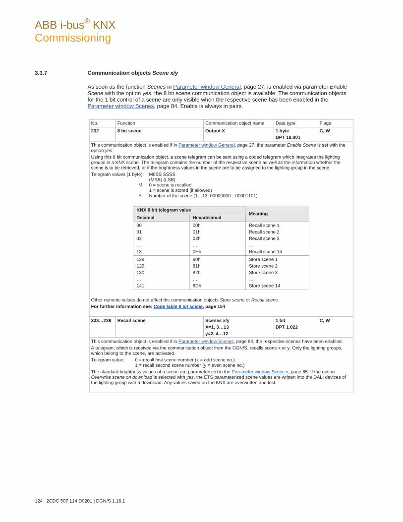
ABB i-bus® KNX Commissioning
124 2CDC 507 114 D0201 | DGN/S 1.16.1
3.3.7 Communication objects Scene x/y
As soon as the function Scenes in Parameter window General, page 27, is enabled via parameter EnableScene with the option yes, the 8 bit scene communication object is available. The communication objects for the 1 bit control of a scene are only visible when the respective scene has been enabled in the Parameter window Scenes, page 84. Enable is always in pairs.
No. Function Communication object name Data type Flags 232 8 bit scene Output X 1 byte
DPT 18.001 C, W
This communication object is enabled if in Parameter window General, page 27, the parameter Enable Scene is set with the option yes. Using this 8 bit communication object, a scene telegram can be sent using a coded telegram which integrates the lighting groups in a KNX scene. The telegram contains the number of the respective scene as well as the information whether the scene is to be retrieved, or if the brightness values in the scene are to be assigned to the lighting group in the scene. Telegram values (1 byte): M0SS SSSS
(MSB) (LSB) M: 0 = scene is recalled 1 = scene is stored (if allowed) S: Number of the scene (1…13: 00000000…00001101)
KNX 8 bit telegram value Decimal Hexadecimal
Meaning
00 01 02 … 13
00h 01h 02h … 0Hh
Recall scene 1 Recall scene 2 Recall scene 3 … Recall scene 14
128 129 130 … 141
80h 81h 82h … 8Dh
Store scene 1 Store scene 2 Store scene 3 … Store scene 14
Other numeric values do not affect the communication objects Store scene or Recall scene. For further information see: Code table 8 bit scene, page 154 233…239 Recall scene Scenes x/y
X=1, 3…13 y=2, 4…12
1 bit DPT 1.022
C, W
This communication object is enabled if in Parameter window Scenes, page 84, the respective scenes have been enabled. A telegram, which is received via the communication object from the DGN/S, recalls scene x or y. Only the lighting groups, which belong to the scene, are activated. Telegram value: 0 = recall first scene number (x = odd scene no.)
1 = recall second scene number (y = even scene no.) The standard brightness values of a scene are parameterized in the Parameter window Scene x, page 85. If the option Overwrite scene on download is selected with yes, the ETS parameterized scene values are written into the DALI devices of the lighting group with a download. Any values saved on the KNX are overwritten and lost.
ABB i-bus® KNX Commissioning
DGN/S 1.16.1 | 2CDC 507 114 D0201 125
No. Function Communication object name Data type Flags 240…246 Store scene Scenes x/y
X=1, 3…13 y=2, 4…12
1 bit DPT 1.022
C, W
This communication object is enabled if in Parameter window Scenes, page 84, the respective scenes have been enabled. A telegram, which is received via this communication object from the DGN/S, causes the DGN/S to save the current bright-ness values of the lighting group, which are part of the scene as new scene brightness values for the scene, and to write in the corresponding lighting groups of the devices. The saved scene values received via the ETS during a download are overwritten and are lost. Telegram value: 0 = saving of the scene brightness values of the first scene no. (x)
1 = saving of the scene brightness values of the second scene no. (y) The scene that is set manually once via the KNX can be protected against overwriting with a download by setting the option no for Overwrite scene on download in the Parameter window Scene x, page 85. In this case, the brightness values parameter-ized in the ETS are not written into the DALI devices of the lighting group. The scene brightness values set manually via the KNX are retained.
Note
Not all 16 lighting groups are considered when saving. Only the lighting groups, which belong to the scene, are considered. Thus, for example, the lamp groups in adjacent rooms, which are not part of the scene, are not changed.
ABB i-bus® KNX Commissioning
126 2CDC 507 114 D0201 | DGN/S 1.16.1
3.3.8 Communication objects function Slave
If the additional function Slave is selected in the Parameter window Gx Group, page 51, the following communication objects appear.
No. Function Communication object name Data type Flags 41, 49… 153, 161 1)
Activate function slave Group x 1 bit DPT 1.003
C, W
This communication object is enabled if in Parameter window Gx Group, page 51, the additional function Slave is enabled. This communication object is used for activation/deactivation of the function Slave. With deactivation, the lighting group behaves like a “normal” lighting group of the group-orientated DGN/S without function Slave. The function Slave can be reactivated, if a telegram with the value 1 is received on the DGN/S via this object. By setting the T flag, the communication object is actively sent after KNX voltage recovery. Telegram value: 0 = Slave not active
1 = activate Slave As long as function Slave is activated, the lighting group is controlled using the brightness value received via communication object Brightness value of slave. In the Parameter window - Gx Slave on page 68, you can parameterize if a switch, brightness value, relative dimming or scene telegram interrupts the function Slave.
Note
With selected function Slave, the DGN/S can only display the switch status via the common communication object Switch/status (no. 40, 48…, 160) on the KNX. There is no separate communication object for the switch status.
41, 49… 153, 161 1)
Activate slave/status Group x 1 bit DPT 1.003
C, W, R, T
This communication object is enabled if in Parameter window Gx Group, page 51, the additional function Slave is enabled and simultaneously in Parameter window - Gx Slave, page 68, the parameter Status response of function slave of the lighting group is programmed with the option yes: via object "Activate slave/status”. In this case, the status of the function Slave is sent on the KNX in addition to the functions described above. 43, 51… 155, 163 1)
Brightness value Brightness value/status
Group x 1 byte DPT 5.001
C, W, T C, W, R, T
This communication object is always enabled in order to enable setting of a brightness value without further parameterization. With activated function Slave, the brightness values received via this communication object are normally ignored. Optionally, however, if a telegram is received on this communication object, function Slave can be deactivated. The respective parameterization can be set in the Parameter window - Gx Slave, page 68. 44, 52… 156, 164 1)
Brightness value of slave Group x 1 byte DPT 5.001
C, W
This communication object is enabled if in Parameter window Gx Group, page 51, the additional function Slave is enabled. The slave output receives the brightness value via this communication object, e.g. from a higher level light controller, which is parameterized as the master. If the function Slave is not active or is latent (standby) after an OFF telegram with the value 0 to the communication object Switch or Switch/status, the telegrams to the communication object Brightness value of slave have no effect. In the Parameter window - Gx Slave on page 68, you can parameterize if a switch, brightness value, relative dimming or scene telegram interrupts the function Slave. Brightness values, which are above or below the predefined max. or min. dimming values (dimming thresholds), are not set. In this case, the dimming limits are set. Telegram value: 0 = OFF, the output is switched, off, the function Slave remains active.
… 255 = 100 %
1) The numbers of the communication objects apply for lighting groups 1…16.
ABB i-bus® KNX Commissioning
DGN/S 1.16.1 | 2CDC 507 114 D0201 127
3.3.9 Communication objects function Sequence
If the additional function Slave is selected in the Parameter window Gx Group, page 51, the following communication objects appear.
No. Function Communication object name Data type Flags 41, 49… 153, 161 1)
Activate function sequence Group x 1 bit DPT 1.003
C, W
This communication object is enabled if in Parameter window Gx Group, page 51, the additional function Sequence is enabled. This communication object is used for activation/deactivation of the function Sequence. With deactivation, the lighting group behaves like a “normal” lighting group of the group-orientated DGN/S without function Sequence. The function Sequence can be reactivated, if a telegram with the value 1 is received on the DGN/S via this object. By setting the T flag, the communication object is actively sent after KNX voltage recovery. Telegram value: 0 = Sequence is deactivated, current brightness is retained
1 = Sequence is activated and started simultaneously As long as function Sequence is activated, the Sequence time curve is initiated by a telegram with the value 1 to one of both communication objects Switch or Switch/status. In the Parameter window - Gx Sequence on page 74, you can parameterize if a switch, brightness value, relative dimming or scene telegram interrupts the function Sequence. For further information see: Parameter window Sequence, page 87, or Sequence, page 142 41, 49… 153, 161 1)
Activate sequence/status Group x 1 bit DPT 1.003
C, W, R, T
This communication object is enabled if in Parameter window Gx Group, page 51, the additional function Sequence is enabled and simultaneously in Parameter window - Gx Sequence, page 74, the parameter Status response of function Sequence of the lighting group is programmed with the option yes: via object "Activate sequence/sStatus”. In this case, the status of the function Sequence is sent via this communication object on the KNX in addition to the functions described above.
1) The numbers of the communication objects apply for lighting groups 1…16.
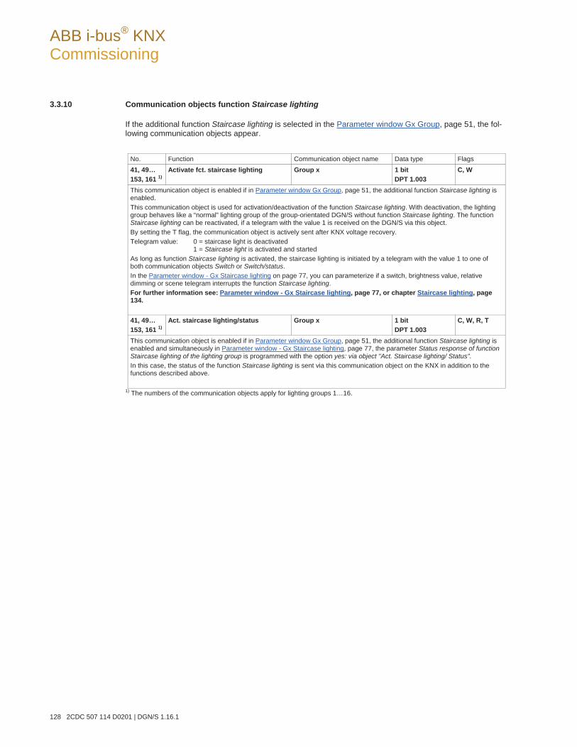
ABB i-bus® KNX Commissioning
128 2CDC 507 114 D0201 | DGN/S 1.16.1
3.3.10 Communication objects function Staircase lighting
If the additional function Staircase lighting is selected in the Parameter window Gx Group, page 51, the fol-lowing communication objects appear.
No. Function Communication object name Data type Flags 41, 49… 153, 161 1)
Activate fct. staircase lighting Group x 1 bit DPT 1.003
C, W
This communication object is enabled if in Parameter window Gx Group, page 51, the additional function Staircase lighting is enabled. This communication object is used for activation/deactivation of the function Staircase lighting. With deactivation, the lighting group behaves like a “normal” lighting group of the group-orientated DGN/S without function Staircase lighting. The function Staircase lighting can be reactivated, if a telegram with the value 1 is received on the DGN/S via this object. By setting the T flag, the communication object is actively sent after KNX voltage recovery. Telegram value: 0 = staircase light is deactivated
1 = Staircase light is activated and started As long as function Staircase lighting is activated, the staircase lighting is initiated by a telegram with the value 1 to one of both communication objects Switch or Switch/status. In the Parameter window - Gx Staircase lighting on page 77, you can parameterize if a switch, brightness value, relative dimming or scene telegram interrupts the function Staircase lighting. For further information see: Parameter window - Gx Staircase lighting, page 77, or chapter Staircase lighting, page 134. 41, 49… 153, 161 1)
Act. staircase lighting/status Group x 1 bit DPT 1.003
C, W, R, T
This communication object is enabled if in Parameter window Gx Group, page 51, the additional function Staircase lighting is enabled and simultaneously in Parameter window - Gx Staircase lighting, page 77, the parameter Status response of function Staircase lighting of the lighting group is programmed with the option yes: via object "Act. Staircase lighting/ Status”. In this case, the status of the function Staircase lighting is sent via this communication object on the KNX in addition to the functions described above.
1) The numbers of the communication objects apply for lighting groups 1…16.
ABB i-bus® KNX Planning and Application
DGN/S 1.16.1 | 2CDC 507 114 D0201 129
4 Planning and Application
In this section, you will find some tips and application examples for practical use of the group-orientated DALI gateway DGN/S 1.16.1.
4.1 Automatic DALI addressing
In order to better appreciate the functionality of the DGN/S, the addressing of the DGN/S is described in this chapter.
For the DGN/S, it is necessary to perform DALI commissioning (configuration). It automatically detects the connected DALI equipment and assigns an address in ascending order, if no DALI address is available.
Note
The DGN/S 1.16.1 does not automatically allocate DALI addressing for DALI equipment if in Parameter window General on page 27, the parameter Enable automatic DALI addressing has been set to no.
As soon as the Gateway operating voltage on the DGN/S has been applied to the DGN/S, it automatically and independently checks the DALI devices connected to the DALI output. This process is also started af-ter a download as well as KNX voltage recovery or Gateway operating voltage recovery, and may take about 60 seconds depending on the number of connected DALI devices. If equipment with DALI interfaces is detected, which has not been assigned with a DALI address (default delivery state, DALI short address 255), the DGN/S will automatically assign a DALI address. The detected DALI devices will be assigned with the first free DALI address (0…63) in the DGN/S. If no DALI addresses are detected, it will receive the first DALI address 0. The second DALI device receives the DALI address 1, etc. The sequence, in which a DALI master, e.g. the DGN/S, identifies a device with a DALI interface, cannot be influenced. If the con-nected DALI device already has a DALI address, e.g. an exchanged device from another system, it will not be changed.
If the new DALI device has a DALI address, which is used in the DGN/S, one of both DALI devices with the same address will be assigned with a new and unused DALI address. Here, the old DALI device, which is already connected to the DGN/S, may receive a new address.
With the DGN/S 1.16.1, you can now control the connected DALI devices with the communication objects DALI output via the KNX without additional DALI group assignment.
The connected DALI devices must be assigned to a lighting group to control individual lighting groups. The assignment is implemented with the external ETS independent DALI-Software-Tool. For further information see: Description DALI-Software-Tool, page Fehler! Textmarke nicht definiert.
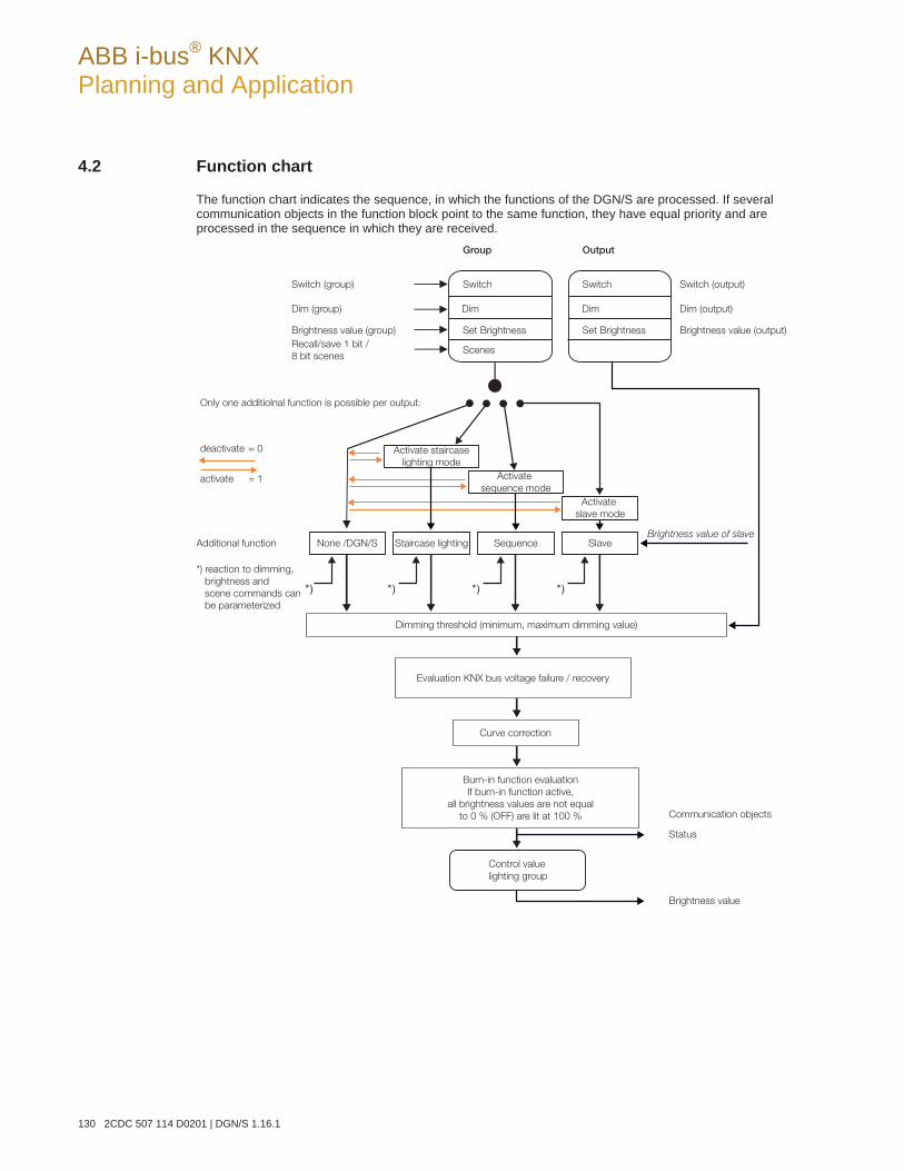
ABB i-bus® KNX Planning and Application
130 2CDC 507 114 D0201 | DGN/S 1.16.1
4.2 Function chart
The function chart indicates the sequence, in which the functions of the DGN/S are processed. If several communication objects in the function block point to the same function, they have equal priority and are processed in the sequence in which they are received.
Communication objects
Status
Brightness value
Control value
lighting group
Burn-in function evaluation
If burn-in function active,
all brightness values are not equal
to 0 % (OFF) are lit at 100 %
Curve correction
Evaluation KNX bus voltage failure / recovery
Dimming threshold (minimum, maximum dimming value)
Brightness value of slaveSlaveSequenceStaircase lightingNone /DGN/S
*) reaction to dimming,
brightness and
scene commands can
be parameterized
Additional function
activate = 1
deactivate = 0
Activate
slave mode
Activate staircase
lighting mode
Only one additiolnal function is possible per output:
Switch (group)
Group Output
Switch Switch Switch (output)
Dim (group) Dim Dim Dim (output)
Brightness value (group) Brightness value (output)Set BrightnessSet Brightness
ScenesRecall/save 1 bit /
8 bit scenes
Activate
sequence mode
ABB i-bus® KNX Planning and Application
DGN/S 1.16.1 | 2CDC 507 114 D0201 131
4.3 Monitoring of lamps and ballasts
With the DGN/S 1.16.1, the malfunction state of the lighting in the building can be broadcast on the KNX. A control panel or control centre can evaluate or display this information. Required repair measures or cor-responding maintenance cycles can be initiated. It is thus possible to integrate the lighting in a higher-order Facility Management system.
The prerequisite is that the lighting equipment is connected to the DGN/S and features a DALI interface compliant to EN 62386 or EN 60929. Different possibilities are available for the fault messages:
A fault on the DALI output is broadcast on the KNX for a lamp and ballast fault. Two separate commu-nication objects (Fault lamp or Fault ballast) are available for this purpose. This information indicates that at least one DALI device on the output has a fault.
One communication object is available for an error message per lighting group. This communication object can contain the information about a lamp fault (Fault lamp), ballast fault (Fault ballast) or a logi-cal OR combination of lamp and ballast fault (Fault ballast or lamp).
The fault status of the individual DALI device can be read via
a coded communication object (Fault group/device). This 1 byte communication object contains the devices or lighting group number (this can be parameterized) and the fault information (Fault ballast or lamp). The function can be taken from the descriptions of the communication objects on page 98.
the communication object Diagnostics is read and provided on the KNX. The function can be taken from the descriptions of the communication objects on page 98.
The number of the DALI device with a fault or a lighting group with a fault (can be parameterized) can be sent as a figure value with the communication object Fault group/device on the KNX. If several faults exist, the number of the next/previous device or the next/previous lighting group can be dis-played via the communication object Switch up next fault alarm. The numbers of devices or lighting groups with a fault are sent via the communication object Number of faults on the KNX.
In order to guarantee correct operation, the DGN/S has to know how many ballasts are to be monitored. This is implemented by one-time activation of the communication object Detect ballasts. With this function, the DGN/S establishes automatically how many ballasts are connected. The DGN/S saves this number as a reference value. If this system has to be extended or reduced, the function Detect ballasts should be re-activated. This process is only necessary if the number of ballasts per output has changed and not when replacing a ballast. Manual detection of the ballasts is also possible by pressing the button on the DGN/S for longer than five seconds. It is also possible to trigger detection of the ballasts in the DALI-Software-Tool.
Note
In order to detect a lamp malfunction, the fault must be sent by the DALI device on the DALI control line. This is generally supported by the DALI ballasts. DALI dimmers and DALI switch actuators often do not have this characteristic. The function can be found in the technical data of the DALI device or by con-sulting the manufacturer of the lamps.
ABB i-bus® KNX Planning and Application
132 2CDC 507 114 D0201 | DGN/S 1.16.1
4.4 Exchange of DALI devices
If a DALI device fails in an existing DALI installation, where DALI addresses are assigned without any gaps, a DALI device as provided in the default state from the factory (without a DALI address assignment) can be used for replacement and will avoid the requirement for re-commissioning. The new DALI device automatically receives the first free DALI address, group assignments and scene parameters of the faulty ballast from the DGN/S and can assume the functions of the failed DALI device with the same technical characteristics.
Note
The parameter Enable automatic DALI addressing in Parameter window General, page 27, must be enabled.
If multiple DALI devices on a DALI output fail or there are gaps in the DALI address assignment, it is not possible to guarantee a unique assignment of the replacement device by the DGN/S. The DGN/S assigns the new DALI device with the first free DALI address. If the new DALI device has a DALI address, which is already used in the DGN/S, one of both DALI devices with the same address will be assigned with a new and unused DALI address. In this way, the fault-free DALI device, which is already on the DGN/S, may receive a new address.
With the DALI-Software-Tool, page Fehler! Textmarke nicht definiert., a correction or exchange of the DALI address, as with the assignment to a lighting group, can be implemented in a simple manner by “Drag and Drop” even without using the ETS.
ABB i-bus® KNX Planning and Application
DGN/S 1.16.1 | 2CDC 507 114 D0201 133
4.5 Burning-in of luminaries
In the case of lamps filled with gas, a burn-in time is recommended. This burn-in process is only required once at the start of commissioning.
Only after this burn-in time fluorescent lamps do have a stable operating value, which ensures the best possible dimming behaviour and an optimum service life. An optimum pressure level is created in the fluo-rescent tube by burning-in.
For installations with dimmable ballasts, many lamp manufacturers make a recommendation that a burn-in time of 20 to 100 hours must be observed. The recommended values are about 20 hours for T8 lamps and 100 hours for T5 lamps. The exact values are available from the luminary's manufacturers. During the burn-in time, the lamps are only switched on at maximum capacity. Dimming is not possible.
The information about burn-in times can often not be found in the catalogue of the lamp manufacturer, but in the descriptions of the electronic ballasts, as the burn-in time only becomes relevant with dimmable sys-tems. Stable operating values and reproducible brightness values are a prerequisite in these installations. Moreover, only poor evaporation of the solid or fluid additives is possible for dimmed lights due to the re-duced capacity, so that in certain circumstances the maximum light yield is only achieved at a later date or not at all. This can lead to the complete replacement of the lights.
According to statements of lighting planners, if fluorescent lamps (particularly T5 lamps) are not burned in, they can even be damaged causing them to fail prematurely.
With the group-oriented DGN/S 1.16.1, it is possible to activate the burn-in time via the communication ob-ject Burn-In lamps and to place individual lighting groups or all lighting groups on the DGN/S in a burn-in state. The lighting groups which are considered during function Burn-in can be set via parameters. During this time, the lamps can only be switched on with 100 % or switched off. Dimming is not possible.
The function Burn-in can only be activated commonly for all lighting groups. In Parameter windowGx Group on page 51, with the parameter Enable with function Burn-in (Object "Burn-in lamps/status"), you can individually determine for each lighting group whether the lighting group should be considered dur-ing burn-in.
The DGN/S 1.16.1 features a counter (1…255 h) for each individual DALI device for the function Burn-in. In this way, the burn-in time counting is undertaken for each individual DALI device in the group, even for overlapping groups, where the DALI device is contained in several lighting groups. The resolution of the timing is set internally to five minutes, even though the time is counted in hours. The DGN/S only indicates the burn-in state but not the remaining or elapsed burn-in time.
If the lamp is switched off during the activated burn-in time, the burn-in counter stops the counting process. Should the lamp be switched on again, the counting process will continue and the remaining time will be rounded off to the nearest five minute step. At Gateway operating voltage failure or KNX voltage failure on the DGN/S, the elapsed burn-in time is sto-red and continues to be used after voltage recovery. The same applies after a download.
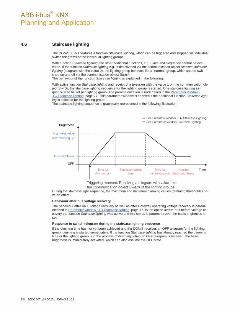
ABB i-bus® KNX Planning and Application
134 2CDC 507 114 D0201 | DGN/S 1.16.1
4.6 Staircase lighting
The DGN/S 1.16.1 features a function Staircase lighting, which can be triggered and stopped via individual switch telegrams of the individual lighting groups.
With function Staircase lighting, the other additional functions, e.g. Slave and Sequence cannot be acti-vated. If the function Staircase lighting e.g. is deactivated via the communication object Activate staircase lighting (telegram with the value 0), the lighting group behaves like a “normal” group, which can be swit-ched on and off via the communication object Switch. The behaviour of the function Staircase lighting is explained in the following.
With active function Staircase lighting and receipt of a telegram with the value 1 on the communication ob-ject Switch, the staircase lighting sequence for the lighting group is started. One staircase lighting se-quence is to be set per lighting group. The parameterization is undertaken in the Parameter window - Gx Staircase lighting, page 77. This parameter window is enabled if the additional function Staircase light-ing is selected for the lighting group. The staircase lighting sequence is graphically represented in the following illustration:
During the staircase light sequence, the maximum and minimum dimming values (dimming thresholds) ha-ve an effect.
Behaviour after bus voltage recovery The behaviour after KNX voltage recovery as well as after Gateway operating voltage recovery is param-eterized in Parameter window - Gx Staircase lighting, page 77. Is the option active, or if before voltage re-covery the function Staircase lighting was active and last status is parameterized, the basis brightness is set.
Response to switch telegram during the staircase lighting sequence If the dimming time has not yet been achieved and the DGN/S receives an OFF telegram for the lighting group, dimming is started immediately. If the function Staircase lighting has already reached the dimming time or the lighting group is in the process of dimming, when an OFF telegram is received, the basis brightness is immediately activated, which can also assume the OFF state.
Brightness value
after dimming up
Basis brightness
OFF
Time
Brightness
Time for
dimming up
Time for
dimming down
Staircase lighting
time
Triggering moment: Receiving a telegram with value 1 via
the communication object Switch of the lighting groups
Runtime
Basis brightness
See Paramete window - Gx Staircase Lighting
See Parameter window Staircase Lighting
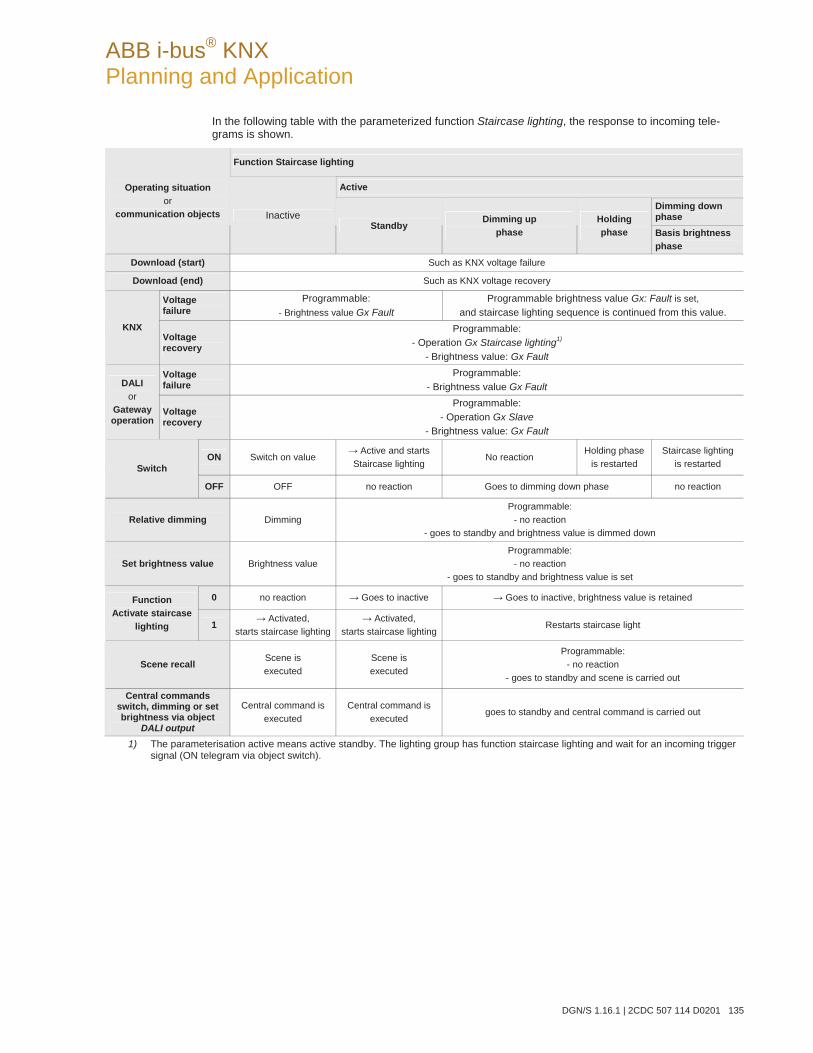
ABB i-bus® KNX Planning and Application
DGN/S 1.16.1 | 2CDC 507 114 D0201 135
In the following table with the parameterized function Staircase lighting, the response to incoming tele-grams is shown.
Function Staircase lighting
Active
Dimming down phase
Operating situation or
communication objects Inactive Standby
Dimming up phase
Holdingphase Basis brightness
phase
Download (start) Such as KNX voltage failure
Download (end) Such as KNX voltage recovery
Voltage failure
Programmable: - Brightness value Gx Fault
Programmable brightness value Gx: Fault is set, and staircase lighting sequence is continued from this value.
KNXVoltage recovery
Programmable: - Operation Gx Staircase lighting1)
- Brightness value: Gx Fault
Voltage failure
Programmable: - Brightness value Gx Fault DALI
or Gateway operation
Voltage recovery
Programmable: - Operation Gx Slave
- Brightness value: Gx Fault
ON Switch on value Active and starts
Staircase lighting No reaction
Holding phase is restarted
Staircase lighting is restarted Switch
OFF OFF no reaction Goes to dimming down phase no reaction
Relative dimming Dimming Programmable:
- no reaction - goes to standby and brightness value is dimmed down
Set brightness value Brightness value Programmable:
- no reaction - goes to standby and brightness value is set
0 no reaction Goes to inactive Goes to inactive, brightness value is retained Function Activate staircase
lighting 1 Activated, starts staircase lighting
Activated, starts staircase lighting
Restarts staircase light
Scene recall Scene is executed
Scene is executed
Programmable: - no reaction
- goes to standby and scene is carried out
Central commands switch, dimming or set brightness via object
DALI output
Central command is executed
Central command is executed
goes to standby and central command is carried out
1) The parameterisation active means active standby. The lighting group has function staircase lighting and wait for an incoming trigger signal (ON telegram via object switch).
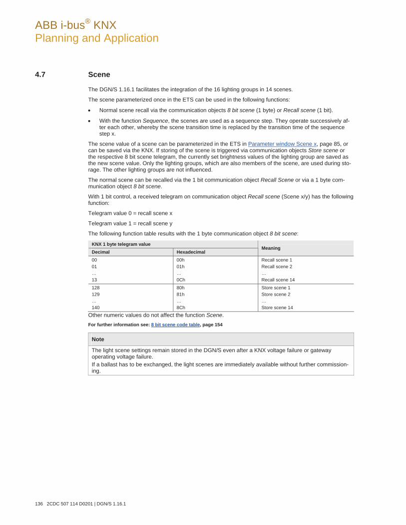
ABB i-bus® KNX Planning and Application
136 2CDC 507 114 D0201 | DGN/S 1.16.1
4.7 Scene
The DGN/S 1.16.1 facilitates the integration of the 16 lighting groups in 14 scenes.
The scene parameterized once in the ETS can be used in the following functions:
Normal scene recall via the communication objects 8 bit scene (1 byte) or Recall scene (1 bit).
With the function Sequence, the scenes are used as a sequence step. They operate successively af-ter each other, whereby the scene transition time is replaced by the transition time of the sequence step x.
The scene value of a scene can be parameterized in the ETS in Parameter window Scene x, page 85, or can be saved via the KNX. If storing of the scene is triggered via communication objects Store scene or the respective 8 bit scene telegram, the currently set brightness values of the lighting group are saved as the new scene value. Only the lighting groups, which are also members of the scene, are used during sto-rage. The other lighting groups are not influenced.
The normal scene can be recalled via the 1 bit communication object Recall Scene or via a 1 byte com-munication object 8 bit scene.
With 1 bit control, a received telegram on communication object Recall scene (Scene x/y) has the following function:
Telegram value 0 = recall scene x
Telegram value 1 = recall scene y
The following function table results with the 1 byte communication object 8 bit scene:
KNX 1 byte telegram value Decimal Hexadecimal
Meaning
00 01 … 13
00h 01h … 0Ch
Recall scene 1 Recall scene 2 … Recall scene 14
128 129 … 140
80h 81h … 8Ch
Store scene 1 Store scene 2 … Store scene 14
Other numeric values do not affect the function Scene. For further information see: 8 bit scene code table, page 154
Note
The light scene settings remain stored in the DGN/S even after a KNX voltage failure or gateway operating voltage failure. If a ballast has to be exchanged, the light scenes are immediately available without further commission-ing.
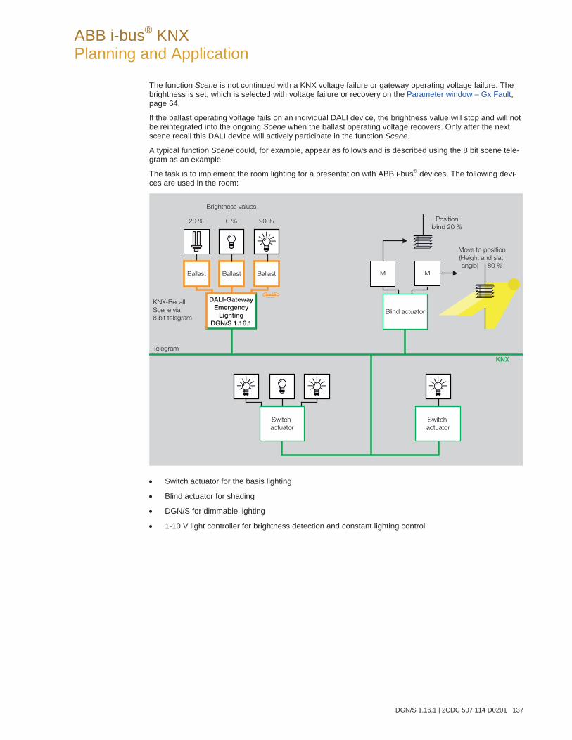
ABB i-bus® KNX Planning and Application
DGN/S 1.16.1 | 2CDC 507 114 D0201 137
The function Scene is not continued with a KNX voltage failure or gateway operating voltage failure. The brightness is set, which is selected with voltage failure or recovery on the Parameter window – Gx Fault, page 64.
If the ballast operating voltage fails on an individual DALI device, the brightness value will stop and will not be reintegrated into the ongoing Scene when the ballast operating voltage recovers. Only after the next scene recall this DALI device will actively participate in the function Scene.
A typical function Scene could, for example, appear as follows and is described using the 8 bit scene tele-gram as an example:
The task is to implement the room lighting for a presentation with ABB i-bus® devices. The following devi-ces are used in the room:
Switch actuator for the basis lighting
Blind actuator for shading
DGN/S for dimmable lighting
1-10 V light controller for brightness detection and constant lighting control
KNX
KNX-Recall
Scene via
8 bit telegram
Telegram
Position
blind 20 %
Move to position
(Height and slat
angle) 80 %
Blind actuator
Switch
actuator
Switch
actuator
Brightness values
20 % 0 % 90 %
M M
DALI-GatewayEmergency
LightingDGN/S 1.16.1
BallastBallast Ballast
ABB i-bus® KNX Planning and Application
138 2CDC 507 114 D0201 | DGN/S 1.16.1
Example
An 8 bit scene (no. 8) comprises of some lamps, which are connected to two switch actuators and a light controller DALI output. Furthermore, two blinds are integrated into the function Scene via a blind actuator. The Scene can be retrieved via a single KNX telegram. The prerequisite for this is that all devices have programmed scene 8 accordingly in their devices. After a telegram has been received, the slave switches on its Scene number 8. The blind actuator moves the blinds to the corresponding posi-tion; the lighting assumes the predefined brightness values and switching states defined by the Scene.
Benefits
The 8 bit scene offers some advantages compared to conventional scene programming via several KNX groups. On the one hand, only a single telegram, which is received by all participants in the scene and implemented accordingly, is sent on the KNX to retrieve a scene. On the other hand, the target positions of the blind, the contact position of the switch actuator outputs and the brightness value of the light controller are each stored in the devices and do not need to be sent via the KNX each time they are to be retrieved.
Note
The scene numbering 1…64 is accessed via the KNX with a telegram value 0…63, whereby the DGN/S 1.16.1 can only be used in one of the first 14 scenes. For further information see: 8 bit scene code table, page 154
ABB i-bus® KNX Planning and Application
DGN/S 1.16.1 | 2CDC 507 114 D0201 139
4.8 Slave
If the function Slave is activated, the lighting group of the DGN/S strictly adheres to the brightness value, which is predefined by the communication object Brightness value of slave. Brightness values on the communication object Brightness value are ignored.
A telegram with the value 0 on the communication object Activate function Slave deactivates function Sla-ve. A telegram with the value 1 reactivates function Slave. In the non-activated state, the lighting group again responds to the brightness values, which are sent via the communications object Brightness value. Dimming, switch, scene or sequence telegrams are also undertaken.
An OFF telegram (receipt of a telegram with the value 0 on the communication object Switch, e.g. by a presence detector) has the effect that the function Slave switches over to standby. During standby mode, the lighting group responds to dimming, scene and sequence telegrams. Furthermore, in standby mode the brightness values, which the DGN/S receives for the communication object Brightness value, are car-ried out. Brightness values that are received via the communication object Brightness value of slave for the lightning group are ignored by the DGN/S. Standby mode is exited if the DGNS receives an ON telegram for the lighting group (receipt of a telegram with the value 1 on the communication object Switch, e.g. by a presence detector) or a telegram with the value 1 on the communication object Activate function Slave. The lighting group is again in slave mode and only responds to the communication object Brightness value of slave.
The function Slave is also put into standby if in Parameter window - Gx Slave, page 70, the reaction to a switch, dimming, brightness value setting telegram, sequence or sequence recall is parameterized with the option Mode deactivate. The function Slave is in standby operation. The lighting group responds again to the communication object Brightness value of slave if a telegram with the value 1 is received on the com-munication object Switch or via the communication object Activate function Slave.
The parameterization no reaction has the effect that no dimming, switch and brightness setting telegram can be executed. In addition, a sequence or scene recall and storing of a scene has no effect.
The parameterized minimum and maximum dimming values also apply in function Slave in the Parameterwindow - Gx Slave, page 70. The undershoot and overshoot of these values are set using the parameter-ized minimum or maximum brightness value. If the master sends the brightness value 0, the lighting is switched off.
The reaction of the function Slave after KNX voltage recovery can be parameterized: The mode (ac-tive/inactive) can be set in Parameter window - Gx Slave, page 70, and the brightness value of the lighting group after KNX voltage recovery can be adjusted in Parameter window – Gx Fault, page 64. If the mode active is parameterized, the parameterized brightness value is initially set after KNX voltage recovery. Subsequently, the next brightness value received via communication object Brightness value of Slave is then set. In the following table, the response to received telegrams with the parameterized function Slave is shown.
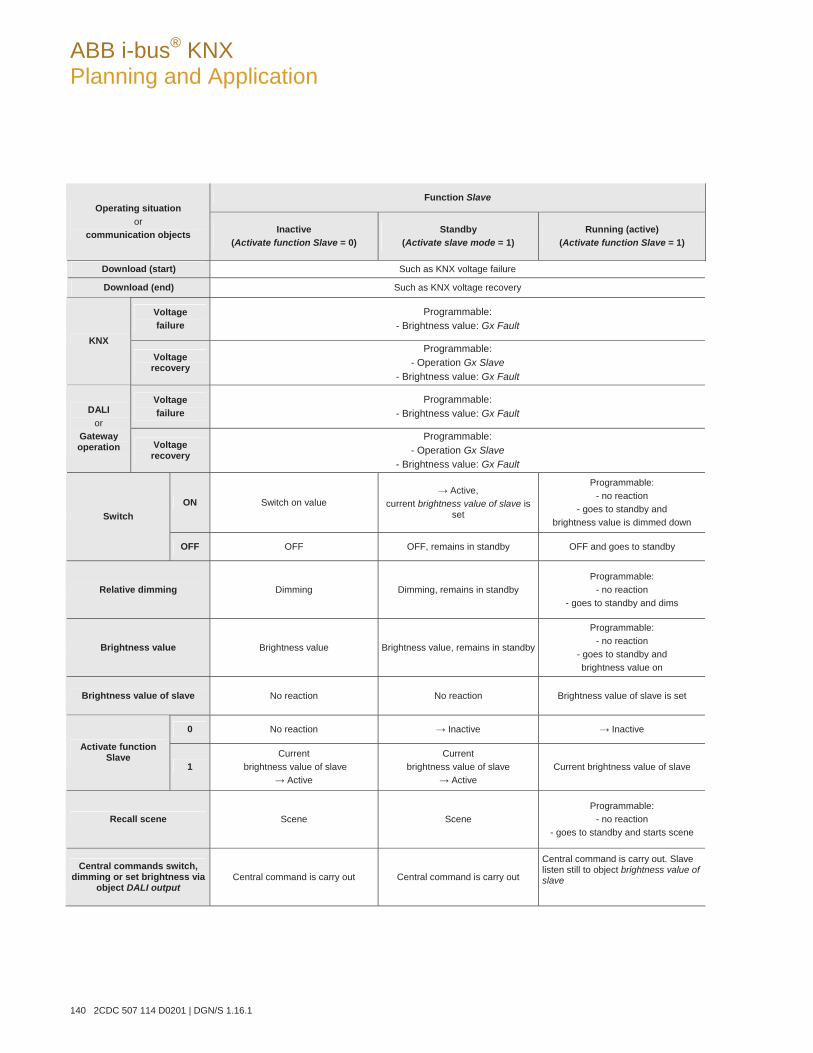
ABB i-bus® KNX Planning and Application
140 2CDC 507 114 D0201 | DGN/S 1.16.1
Function SlaveOperating situation
or communication objects Inactive
(Activate function Slave = 0) Standby
(Activate slave mode = 1) Running (active)
(Activate function Slave = 1)
Download (start) Such as KNX voltage failure
Download (end) Such as KNX voltage recovery
Voltage failure
Programmable: - Brightness value: Gx Fault
KNX
Voltage recovery
Programmable: - Operation Gx Slave
- Brightness value: Gx Fault
Voltage failure
Programmable: - Brightness value: Gx Fault DALI
or Gateway operation Voltage
recovery
Programmable: - Operation Gx Slave
- Brightness value: Gx Fault
ON Switch on value Active,
current brightness value of slave is set
Programmable: - no reaction
- goes to standby and brightness value is dimmed down Switch
OFF OFF OFF, remains in standby OFF and goes to standby
Relative dimming Dimming Dimming, remains in standby Programmable:
- no reaction - goes to standby and dims
Brightness value Brightness value Brightness value, remains in standby
Programmable: - no reaction
- goes to standby and brightness value on
Brightness value of slave No reaction No reaction Brightness value of slave is set
0 No reaction Inactive Inactive
Activate function Slave
1Current
brightness value of slave Active
Current brightness value of slave
Active Current brightness value of slave
Recall scene Scene Scene Programmable:
- no reaction - goes to standby and starts scene
Central commands switch, dimming or set brightness via
object DALI outputCentral command is carry out Central command is carry out
Central command is carry out. Slave listen still to object brightness value of slave
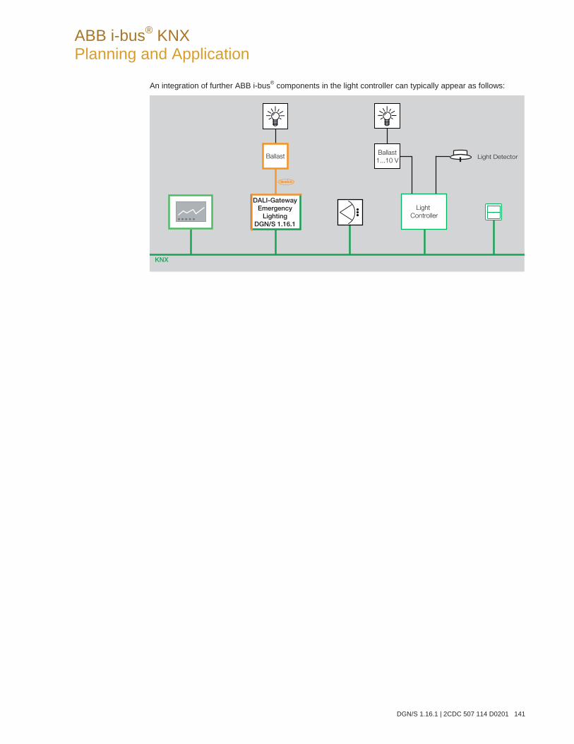
ABB i-bus® KNX Planning and Application
DGN/S 1.16.1 | 2CDC 507 114 D0201 141
An integration of further ABB i-bus® components in the light controller can typically appear as follows:
KNX
DALI-GatewayEmergency
LightingDGN/S 1.16.1
Ballast Light DetectorBallast
1...10 V
Light
Controller
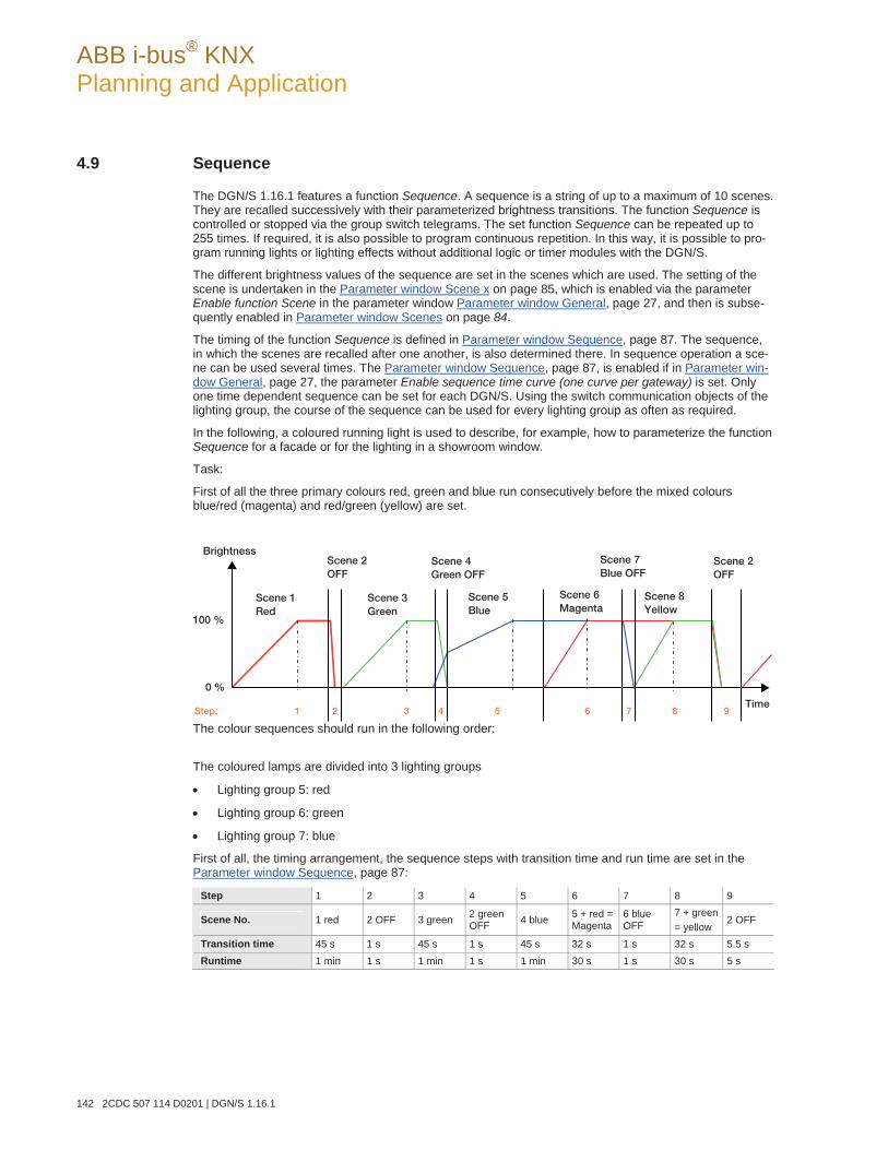
ABB i-bus® KNX Planning and Application
142 2CDC 507 114 D0201 | DGN/S 1.16.1
4.9 Sequence
The DGN/S 1.16.1 features a function Sequence. A sequence is a string of up to a maximum of 10 scenes. They are recalled successively with their parameterized brightness transitions. The function Sequence is controlled or stopped via the group switch telegrams. The set function Sequence can be repeated up to 255 times. If required, it is also possible to program continuous repetition. In this way, it is possible to pro-gram running lights or lighting effects without additional logic or timer modules with the DGN/S.
The different brightness values of the sequence are set in the scenes which are used. The setting of the scene is undertaken in the Parameter window Scene x on page 85, which is enabled via the parameter Enable function Scene in the parameter window Parameter window General, page 27, and then is subse-quently enabled in Parameter window Scenes on page 84.
The timing of the function Sequence is defined in Parameter window Sequence, page 87. The sequence, in which the scenes are recalled after one another, is also determined there. In sequence operation a sce-ne can be used several times. The Parameter window Sequence, page 87, is enabled if in Parameter win-dow General, page 27, the parameter Enable sequence time curve (one curve per gateway) is set. Only one time dependent sequence can be set for each DGN/S. Using the switch communication objects of the lighting group, the course of the sequence can be used for every lighting group as often as required.
In the following, a coloured running light is used to describe, for example, how to parameterize the function Sequence for a facade or for the lighting in a showroom window.
Task:
First of all the three primary colours red, green and blue run consecutively before the mixed colours blue/red (magenta) and red/green (yellow) are set.
The colour sequences should run in the following order:
The coloured lamps are divided into 3 lighting groups
Lighting group 5: red
Lighting group 6: green
Lighting group 7: blue
First of all, the timing arrangement, the sequence steps with transition time and run time are set in the Parameter window Sequence, page 87:
Step 1 2 3 4 5 6 7 8 9
Scene No. 1 red 2 OFF 3 green 2 green OFF 4 blue 5 + red =
Magenta 6 blue OFF
7 + green= yellow
2 OFF
Transition time 45 s 1 s 45 s 1 s 45 s 32 s 1 s 32 s 5.5 s Runtime 1 min 1 s 1 min 1 s 1 min 30 s 1 s 30 s 5 s
Step: 1 2 3 4 5 6 7 8 9
Scene 1 Red
Scene 2 OFF
Scene 3 Green
Scene 4 Green OFF
Scene 5 Blue
Scene 6 Magenta
Scene 7 Blue OFF
Scene 8 Yellow
Scene 2 OFF
0 %
100 %
Brightness
Time
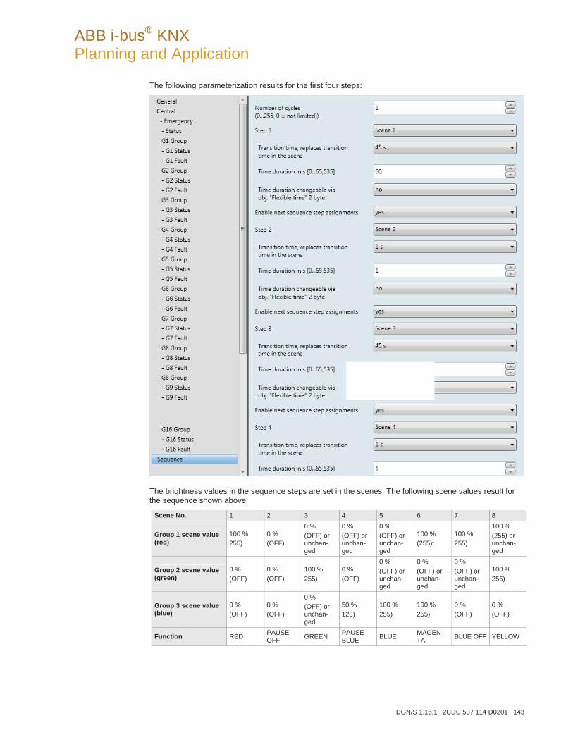
ABB i-bus® KNX Planning and Application
DGN/S 1.16.1 | 2CDC 507 114 D0201 143
The following parameterization results for the first four steps:
The brightness values in the sequence steps are set in the scenes. The following scene values result for the sequence shown above:
Scene No. 1 2 3 4 5 6 7 8
Group 1 scene value (red)
100 % 255)
0 % (OFF)
0 % (OFF) or unchan-ged
0 % (OFF) or unchan-ged
0 % (OFF) or unchan-ged
100 % (255)t
100 % 255)
100 % (255) or unchan-ged
Group 2 scene value (green)
0 % (OFF)
0 % (OFF)
100 % 255)
0 % (OFF)
0 % (OFF) or unchan-ged
0 % (OFF) or unchan-ged
0 % (OFF) or unchan-ged
100 % 255)
Group 3 scene value (blue)
0 % (OFF)
0 % (OFF)
0 % (OFF) or unchan-ged
50 % 128)
100 % 255)
100 % 255)
0 % (OFF)
0 % (OFF)
Function RED PAUSE OFF GREEN PAUSE
BLUE BLUE MAGEN-TA BLUE OFF YELLOW
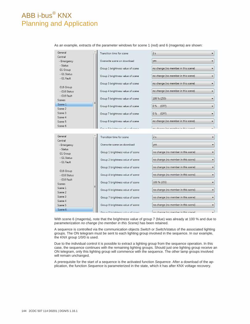
ABB i-bus® KNX Planning and Application
144 2CDC 507 114 D0201 | DGN/S 1.16.1
As an example, extracts of the parameter windows for scene 1 (red) and 6 (magenta) are shown:
With scene 6 (magenta), note that the brightness value of group 7 (blue) was already at 100 % and due to parameterization no change (no member in this Scene) has been retained.
A sequence is controlled via the communication objects Switch or Switch/status of the associated lighting groups. The ON telegram must be sent to each lighting group involved in the sequence. In our example, the KNX group 1/0/0 is used.
Due to the individual control it is possible to extract a lighting group from the sequence operation. In this case, the sequence continues with the remaining lighting groups. Should just one lighting group receive an ON telegram, only this lighting group will commence with the sequence. The other lamp groups involved will remain unchanged.
A prerequisite for the start of a sequence is the activated function Sequence. After a download of the ap-plication, the function Sequence is parameterized in the state, which it has after KNX voltage recovery.
ABB i-bus® KNX Planning and Application
DGN/S 1.16.1 | 2CDC 507 114 D0201 145
The parameterization is undertaken in the Parameter window - Gx Sequence, page 74. If the default val-ues are retained, the sequence is automatically activated after download. The function Sequence is in standby and can be started at any time by an ON telegram (value 1) to the communication objects Switch or Switch/status of the lighting group which are members of the sequence. Alternatively, the function Se-quence can be started via the communication objects Activate function Sequence of the lighting groups members.
The function Sequence is often repeated as parameterized in Parameter window Sequence on page 87. It is possible to repeat the sequence up to 255 times or to allow it to run endlessly. The function Sequence can be interrupted at any time by an OFF telegram (value 0) to the communication object Switch of the re-spective lighting group.
The function Sequence jumps with the respective transition time to the final scene and then goes to stand-by. In this state, the function Sequence can be restarted by an ON telegram (value 1) at any time. If the function Sequence is in standby mode, where it is not operating, it can be switched off with an OFF tele-gram. The function Sequence operation remains in standby mode in this case.
If the DGN/S receives a telegram with the value 0 on the communication object Activate function Se-quence for a lighting group, the function Sequence is terminated and the current brightness of the lighting group is retained. This is independent of whether the function Sequence is operating or in standby mode. A renewed activation is implemented by a telegram with the value 1 to the communication object Activatefunction Sequence. The function Sequence is activated, the function Sequence is started simultaneously.
The response to a dimming, set brightness value and scene telegram during function Sequence can be parameterized in the Parameter window - Gx Sequence, page 74. The telegram can be ignored or the function Sequence can be deactivated, so that the lighting group reacts as a “normal” lighting group and can only be reactivated by a telegram with the value 1 to the communication object Activate function Se-quence.
Whether the function Sequence for a lighting group is activated is displayed via the communication object Activate sequence/status or displayed in bit 14 in the diagnostics byte.
The state of function Sequence after Gateway supply voltage recovery as well as after KNX voltage recov-ery is parameterized in the Parameter window - Gx Sequence, page 74.
In the following table, the response to received telegrams with the parameterized function Sequence is shown:
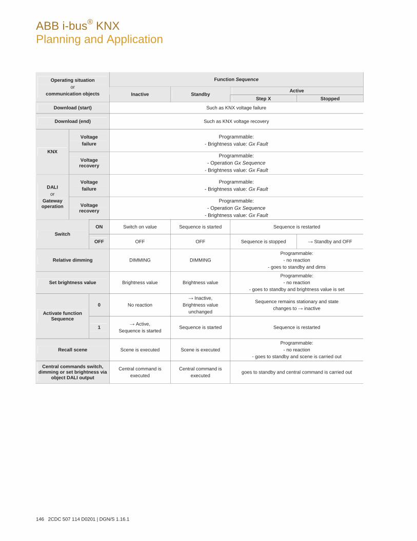
ABB i-bus® KNX Planning and Application
146 2CDC 507 114 D0201 | DGN/S 1.16.1
Function Sequence
Active
Operating situation or
communication objects Inactive Standby Step X Stopped
Download (start) Such as KNX voltage failure
Download (end) Such as KNX voltage recovery
Voltage failure
Programmable: - Brightness value: Gx Fault
KNX
Voltage recovery
Programmable: - Operation Gx Sequence
- Brightness value: Gx Fault
Voltage failure
Programmable: - Brightness value: Gx Fault DALI
or Gateway operation Voltage
recovery
Programmable: - Operation Gx Sequence
- Brightness value: Gx Fault
ON Switch on value Sequence is started Sequence is restarted Switch
OFF OFF OFF Sequence is stopped Standby and OFF
Relative dimming DIMMING DIMMING Programmable:
- no reaction - goes to standby and dims
Set brightness value Brightness value Brightness value Programmable:
- no reaction - goes to standby and brightness value is set
0 No reaction Inactive,
Brightness value unchanged
Sequence remains stationary and state changes to inactive
Activate function Sequence
1 Active, Sequence is started
Sequence is started Sequence is restarted
Recall scene Scene is executed Scene is executed Programmable:
- no reaction - goes to standby and scene is carried out
Central commands switch, dimming or set brightness via
object DALI output
Central command is executed
Central command is executed
goes to standby and central command is carried out
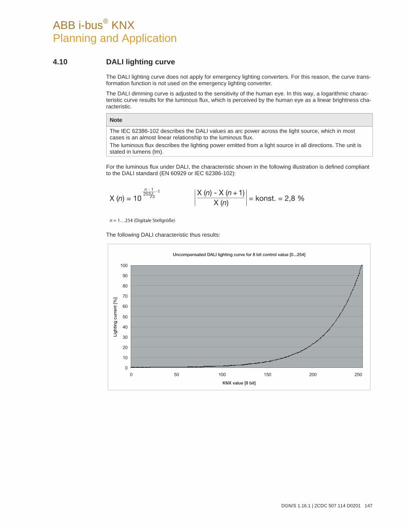
ABB i-bus® KNX Planning and Application
DGN/S 1.16.1 | 2CDC 507 114 D0201 147
4.10 DALI lighting curve
The DALI lighting curve does not apply for emergency lighting converters. For this reason, the curve trans-formation function is not used on the emergency lighting converter.
The DALI dimming curve is adjusted to the sensitivity of the human eye. In this way, a logarithmic charac-teristic curve results for the luminous flux, which is perceived by the human eye as a linear brightness cha-racteristic.
Note
The IEC 62386-102 describes the DALI values as arc power across the light source, which in most cases is an almost linear relationship to the luminous flux. The luminous flux describes the lighting power emitted from a light source in all directions. The unit is stated in lumens (lm).
For the luminous flux under DALI, the characteristic shown in the following illustration is defined compliant to the DALI standard (EN 60929 or IEC 62386-102):
The following DALI characteristic thus results:
X (n) - X (n + 1) = konst. = 2,8 % X (n)
0
10
20
30
40
50
60
70
80
90
100
0 50 100 150 200 250
KNX value [8 bit]
Uncompensated DALI lighting curve for 8 bit control value [0...254]
Lig
htin
g c
urre
nt [%
]

ABB i-bus® KNX Planning and Application
148 2CDC 507 114 D0201 | DGN/S 1.16.1
A KNX value [%] 0 0.4 24 33 49 57 67 77 82 86 90 92 95 97 98 100B KNX value 0 1 60 85 126 144 170 195 210 220 229 235 241 246 250 255C DALI value 0 1 60 85 126 144 170 195 210 220 229 235 241 246 250 254D Luminous flux [%] 0 0.1 0.5 1 3 5 10 20 30 40 50 60 70 80 90 100
E KNX status brightness value 0 1 60 85 126 144 170 195 210 220 229 235 241 246 250 255
The table assumes ideal DALI equipment (DALI dimming range 0.1…100 %) and in the DGN/S a KNX dimming range of 0.4…100 %.
Row A and B are the brightness value of the DGN/S received via the KNX as a digital figure value (0…255) or in % (0…100). This value is implemented by the DGN/S on the DALI (row C). It results in the luminous flux, which is emitted by the lighting equipment via the DALI characteristic (row D). The DGN/S then sends the status of the brightness value (row E) back on the KNX.
The dimmable range printed on the ballast relates to the luminous flux. Typical specifications are 3 % or 0.2 %, which due to the logarithmic nature of the DALI curve, are the KNX values of 49 % (126) or 10 % (26).
The maximum possible dimming range can only be set with DALI equipment, which has a dimming range up to 0.1 % (KNX value 1 or 100/255 % = 0.4 %). Other DALI equipment has a limited dimming range. This value is a physical property of the ballast and cannot be changed. This dimming limit has nothing to do with the minimum dimming value parameterised in the application.
As an example, in the following, DALI equipment with a minimum physical luminous flux of 3 % can be ob-served. In the KNX, a dimming range of 126…254 is thus available. This means, the lowest brightness va-lue that can be set and fed back on the KNX is 126 or 50 %. KNX values, which are less than 126 or 50 %, are set by the DALI equipment to the threshold value and fed back by the DGN/S on the KNX.
A KNX value [%] 0 0.4 3 10 24 33 49 57 90 92 95 97 98 100B KNX value 0 1 8 26 60 85 126 144 229 235 241 246 250 255C DALI value 0 1 8 26 60 85 126 144 229 235 241 246 250 254D Luminous flux [%] 0 3 3 3 3 3 3 5 50 60 70 80 90 100
E KNX status brightness value 0 126 12
6 126 126 126 126 144 229 235 241 246 250 255
The characteristic curve described in the following section is represented as the usable range of the ballast with the control value range for the brightness value on the KNX. In this way, a higher resolution of the brightness values on the KNX is possible. However, nothing changes in the physical threshold values of the ballast and the light yield.
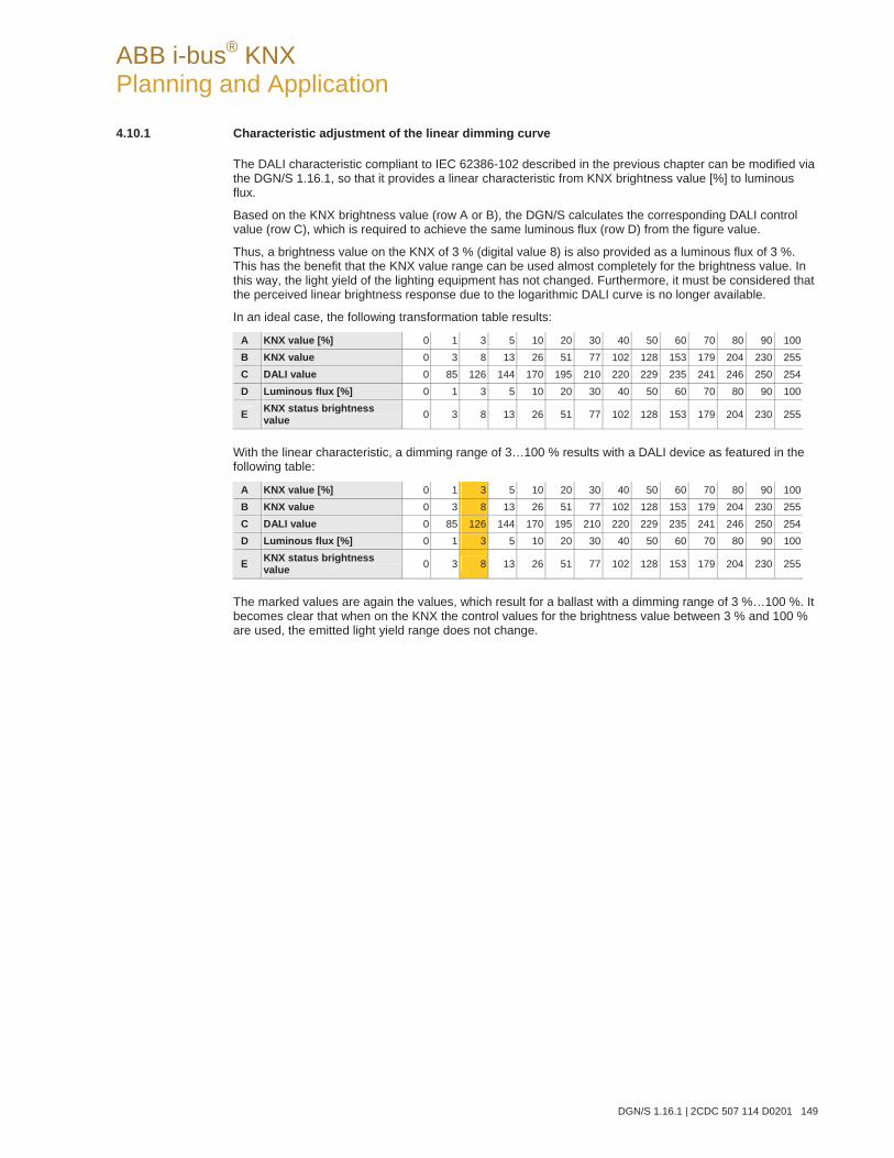
ABB i-bus® KNX Planning and Application
DGN/S 1.16.1 | 2CDC 507 114 D0201 149
4.10.1 Characteristic adjustment of the linear dimming curve
The DALI characteristic compliant to IEC 62386-102 described in the previous chapter can be modified via the DGN/S 1.16.1, so that it provides a linear characteristic from KNX brightness value [%] to luminous flux.
Based on the KNX brightness value (row A or B), the DGN/S calculates the corresponding DALI control value (row C), which is required to achieve the same luminous flux (row D) from the figure value.
Thus, a brightness value on the KNX of 3 % (digital value 8) is also provided as a luminous flux of 3 %. This has the benefit that the KNX value range can be used almost completely for the brightness value. In this way, the light yield of the lighting equipment has not changed. Furthermore, it must be considered that the perceived linear brightness response due to the logarithmic DALI curve is no longer available.
In an ideal case, the following transformation table results:
A KNX value [%] 0 1 3 5 10 20 30 40 50 60 70 80 90 100B KNX value 0 3 8 13 26 51 77 102 128 153 179 204 230 255C DALI value 0 85 126 144 170 195 210 220 229 235 241 246 250 254D Luminous flux [%] 0 1 3 5 10 20 30 40 50 60 70 80 90 100
E KNX status brightness value 0 3 8 13 26 51 77 102 128 153 179 204 230 255
With the linear characteristic, a dimming range of 3…100 % results with a DALI device as featured in the following table:
A KNX value [%] 0 1 3 5 10 20 30 40 50 60 70 80 90 100B KNX value 0 3 8 13 26 51 77 102 128 153 179 204 230 255C DALI value 0 85 126 144 170 195 210 220 229 235 241 246 250 254D Luminous flux [%] 0 1 3 5 10 20 30 40 50 60 70 80 90 100
E KNX status brightness value 0 3 8 13 26 51 77 102 128 153 179 204 230 255
The marked values are again the values, which result for a ballast with a dimming range of 3 %…100 %. It becomes clear that when on the KNX the control values for the brightness value between 3 % and 100 % are used, the emitted light yield range does not change.
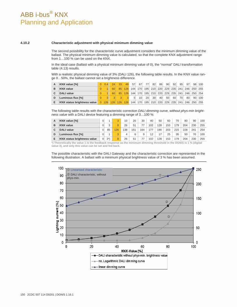
ABB i-bus® KNX Planning and Application
150 2CDC 507 114 D0201 | DGN/S 1.16.1
4.10.2 Characteristic adjustment with physical minimum dimming value
The second possibility for the characteristic curve adjustment considers the minimum dimming value of the ballast. The physical minimum dimming value is calculated, so that the complete KNX adjustment range from 1…100 % can be used on the KNX.
In the ideal case (ballast with a physical minimum dimming value of 0), the “normal” DALI transformation table (4.13) results.
With a realistic physical dimming value of 3% (DALI 126), the following table results. In the KNX value ran-ge 0…50%, the ballast cannot set a brightness difference.
A KNX value [%] 0 0.4 24 33 49 57 67 77 82 86 90 92 95 97 98 100B KNX value 0 1 60 85 126 144 170 195 210 220 229 235 241 246 250 255C DALI value 0 1 60 85 126 144 170 195 210 220 229 235 241 246 250 254D Luminous flux [%] 0 3 3 3 3 5 10 20 30 40 50 60 70 80 90 100E KNX status brightness value 0 126 126 126 126 144 170 195 210 220 229 235 241 246 250 255
The following table results with the characteristic correction DALI dimming curve, without phys-min bright-ness value with a DALI device featuring a dimming range of 3…100 %:
A KNX value [%] 0 1 3 10 20 30 40 50 60 70 80 90 100 B KNX value 0 3 8 26 51 77 102 128 153 179 204 230 255 C DALI value 0 85 126 138 151 164 177 190 203 215 228 241 254 D Luminous flux [%] 0 1 3 4 6 9 12 17 25 35 50 70 100 E KNX status brightness value 0 3*) 8 26 51 77 102 128 153 179 204 230 255
*) Theoretically the value 1 is the feedback response as the minimum dimming threshold in the DGN/S is 1 % (digital value 3), and only this value can be set and fed back.
The possible characteristic with the DALI Gateway and the characteristic correction are represented in the following illustration. A ballast with a minimum physical brightness value of 3 % has been assumed.
Linearised characteristic DALI characteristic, without
phys-min.
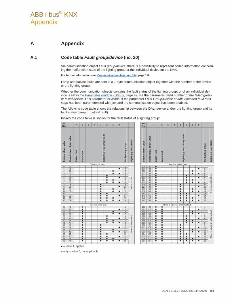
ABB i-bus® KNX Appendix
DGN/S 1.16.1 | 2CDC 507 114 D0201 151
A Appendix
A.1 Code table Fault group/device (no. 20)
Via communication object Fault group/device, there is a possibility to represent coded information concern-ing the malfunction state of the lighting group or the individual device on the KNX. For further information see: Communication object no. 104, page 110.
Lamp and ballast faults are sent in a 1 byte communication object together with the number of the device or the lighting group.
Whether the communication objects contains the fault status of the lighting group, or of an individual de-vice is set in the Parameter window - Status, page 42, via the parameter Send number of the failed group or failed device. This parameter is visible, if the parameter Fault Group/Device enable encoded fault mes-sage has been parameterised with yes and the communication object has been enabled.
The following code table shows the relationship between the DALI device and/or the lighting group and its fault status (lamp or ballast fault).
Initially the code table is shown for the fault status of a lighting group: BitNo. 7 6 5 4 3 2 1 0 Bit
No. 7 6 5 4 3 2 1 0
Dec
imal
obj
ect v
alue
Hex
adec
imal
obj
ect v
alue
Bal
last
faul
t
Lam
p fa
ult
Ligh
ting
grou
p bi
nary
cod
e
No.
ligh
ting
grou
p
Ligh
ting
grou
p st
atus
Dec
imal
obj
ect v
alue
Hex
adec
imal
obj
ect v
alue
Bal
last
faul
t
Lam
p fa
ult
Ligh
ting
grou
p bi
nary
cod
e
No.
ligh
ting
grou
p
Ligh
ting
grou
p st
atus
There is no fault. There is a ballast fault.0 00 1 128 80 11 01 2 129 81 22 02 3 130 82 33 03 4 131 83 44 04 5 132 84 55 05 6 133 85 66 06 7 134 86 77 07 8 135 87 88 08 9 136 88 99 09 10 137 89 10
10 0A 11 138 8A 1111 0B 12 139 8B 1212 0C 13 140 8C 1313 0D 14 141 8D 1414 0E 15 142 8E 1515 0F 16
Ther
e is
no
faul
t.
143 8F 16
Ther
e is
a b
alla
st fa
ult.
There is a lamp fault. There is a ballast and lamp fault.
64 40 1 192 C0 165 41 2 193 C1 266 42 3 194 C2 367 43 4 195 C3 468 44 5 196 C4 569 45 6 197 C5 670 46 7 198 C6 771 47 8 199 C7 872 48 9 200 C8 973 49 10 201 C9 1074 4A 11 202 CA 1175 4B 12 203 CB 1276 4C 13 204 CC 1377 4D 14 205 CD 1478 4E 15 206 CE 1579 4F 16
Ther
e is
a la
mp
faul
t.
207 CF 16
Ther
e is
a b
alla
st a
nd la
mp
faul
t.
= value 1, applies
empty = value 0, not applicable
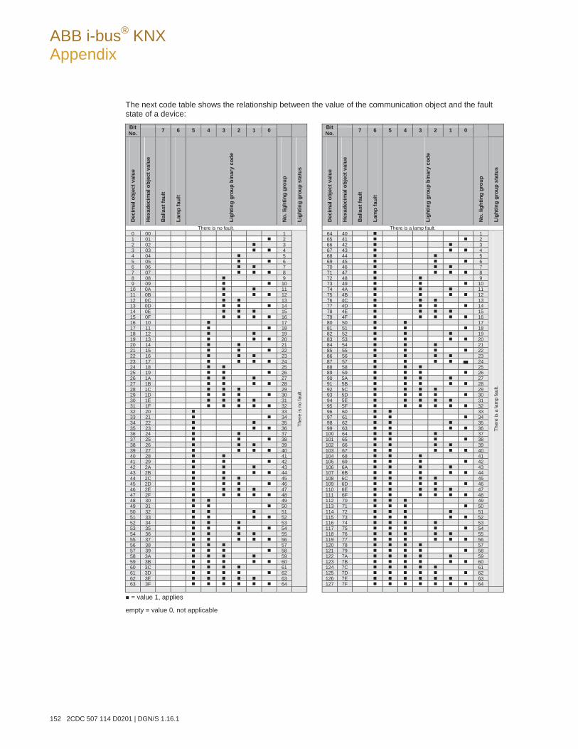
ABB i-bus® KNX Appendix
152 2CDC 507 114 D0201 | DGN/S 1.16.1
The next code table shows the relationship between the value of the communication object and the fault state of a device:
BitNo. 7 6 5 4 3 2 1 0 Bit
No. 7 6 5 4 3 2 1 0D
ecim
al o
bjec
t val
ue
Hex
adec
imal
obj
ect v
alue
Bal
last
faul
t
Lam
p fa
ult
Ligh
ting
grou
p bi
nary
cod
e
No.
ligh
ting
grou
p
Ligh
ting
grou
p st
atus
Dec
imal
obj
ect v
alue
Hex
adec
imal
obj
ect v
alue
Bal
last
faul
t
Lam
p fa
ult
Ligh
ting
grou
p bi
nary
cod
e
No.
ligh
ting
grou
p
Ligh
ting
grou
p st
atus
There is no fault. There is a lamp fault. 0 00 1 64 40 11 01 2 65 41 22 02 3 66 42 33 03 4 67 43 44 04 5 68 44 55 05 6 69 45 66 06 7 70 46 77 07 8 71 47 88 08 9 72 48 99 09 10 73 49 10
10 0A 11 74 4A 1111 0B 12 75 4B 1212 0C 13 76 4C 1313 0D 14 77 4D 1414 0E 15 78 4E 1515 0F 16 79 4F 1616 10 17 80 50 1717 11 18 81 51 1818 12 19 82 52 1919 13 20 83 53 2020 14 21 84 54 2121 15 22 85 55 2222 16 23 86 56 2323 17 24 87 57 2424 18 25 88 58 2525 19 26 89 59 2626 1A 27 90 5A 2727 1B 28 91 5B 2828 1C 29 92 5C 2929 1D 30 93 5D 3030 1E 31 94 5E 3131 1F 32 95 5F 3232 20 33 96 60 3333 21 34 97 61 3434 22 35 98 62 3535 23 36 99 63 3636 24 37 100 64 3737 25 38 101 65 3838 26 39 102 66 3939 27 40 103 67 4040 28 41 104 68 4141 29 42 105 69 4242 2A 43 106 6A 4343 2B 44 107 6B 4444 2C 45 108 6C 4545 2D 46 109 6D 4646 2E 47 110 6E 4747 2F 48 111 6F 4848 30 49 112 70 4949 31 50 113 71 5050 32 51 114 72 5151 33 52 115 73 5252 34 53 116 74 5353 35 54 117 75 5454 36 55 118 76 5555 37 56 119 77 5656 38 57 120 78 5757 39 58 121 79 5858 3A 59 122 7A 5959 3B 60 123 7B 6060 3C 61 124 7C 6161 3D 62 125 7D 6262 3E 63 126 7E 6363 3F 64
Ther
e is
no
faul
t.
127 7F 64
Ther
e is
a la
mp
faul
t.
= value 1, applies
empty = value 0, not applicable
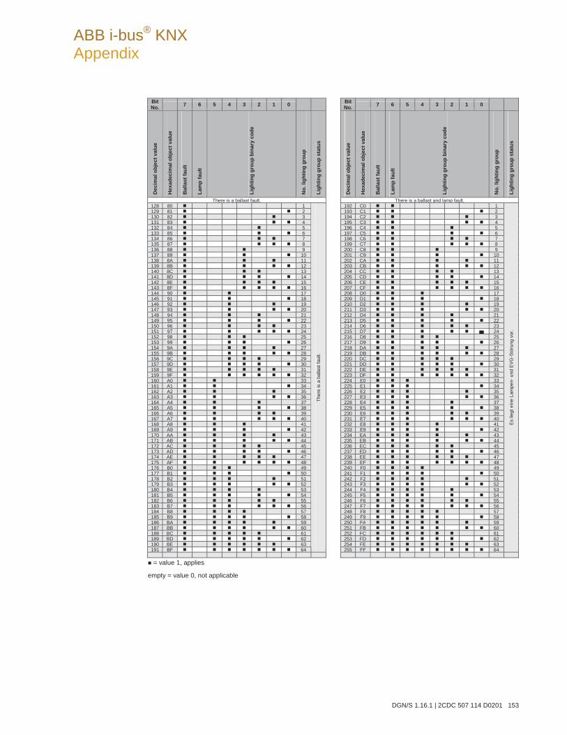
ABB i-bus® KNX Appendix
DGN/S 1.16.1 | 2CDC 507 114 D0201 153
BitNo. 7 6 5 4 3 2 1 0 Bit
No. 7 6 5 4 3 2 1 0
Dec
imal
obj
ect v
alue
Hex
adec
imal
obj
ect v
alue
Bal
last
faul
t
Lam
p fa
ult
Ligh
ting
grou
p bi
nary
cod
e
No.
ligh
ting
grou
p
Ligh
ting
grou
p st
atus
Dec
imal
obj
ect v
alue
Hex
adec
imal
obj
ect v
alue
Bal
last
faul
t
Lam
p fa
ult
Ligh
ting
grou
p bi
nary
cod
e
No.
ligh
ting
grou
p
Ligh
ting
grou
p st
atus
There is a ballast fault. There is a ballast and lamp fault.128 80 1 192 C0 1129 81 2 193 C1 2130 82 3 194 C2 3131 83 4 195 C3 4132 84 5 196 C4 5133 85 6 197 C5 6134 86 7 198 C6 7135 87 8 199 C7 8136 88 9 200 C8 9137 89 10 201 C9 10138 8A 11 202 CA 11139 8B 12 203 CB 12140 8C 13 204 CC 13141 8D 14 205 CD 14142 8E 15 206 CE 15143 8F 16 207 CF 16144 90 17 208 D0 17145 91 18 209 D1 18146 92 19 210 D2 19147 93 20 211 D3 20148 94 21 212 D4 21149 95 22 213 D5 22150 96 23 214 D6 23151 97 24 215 D7 24152 98 25 216 D8 25153 99 26 217 D9 26154 9A 27 218 DA 27155 9B 28 219 DB 28156 9C 29 220 DC 29157 9D 30 221 DD 30158 9E 31 222 DE 31159 9F 32 223 DF 32160 A0 33 224 E0 33161 A1 34 225 E1 34162 A2 35 226 E2 35163 A3 36 227 E3 36164 A4 37 228 E4 37165 A5 38 229 E5 38166 A6 39 230 E6 39167 A7 40 231 E7 40168 A8 41 232 E8 41169 A9 42 233 E9 42170 AA 43 234 EA 43171 AB 44 235 EB 44172 AC 45 236 EC 45173 AD 46 237 ED 46174 AE 47 238 EE 47175 AF 48 239 EF 48176 B0 49 240 F0 49177 B1 50 241 F1 50178 B2 51 242 F2 51179 B3 52 243 F3 52180 B4 53 244 F4 53181 B5 54 245 F5 54182 B6 55 246 F6 55183 B7 56 247 F7 56184 B8 57 248 F8 57185 B9 58 249 F9 58186 BA 59 250 FA 59187 BB 60 251 FB 60188 BC 61 252 FC 61189 BD 62 253 FD 62190 BE 63 254 FE 63191 BF 64
Ther
e is
a b
alla
st fa
ult.
255 FF 64
Es li
egt e
ine
Lam
pen-
und
EVG
-Stö
rung
vor
.
= value 1, applies
empty = value 0, not applicable
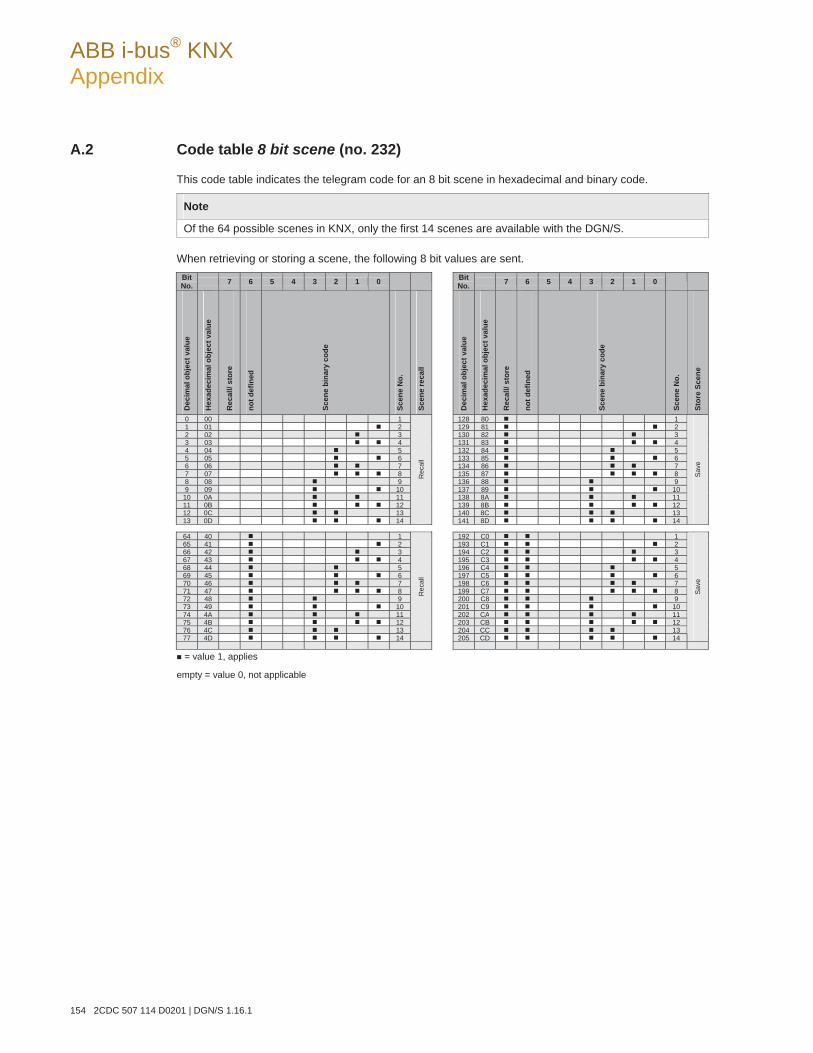
ABB i-bus® KNX Appendix
154 2CDC 507 114 D0201 | DGN/S 1.16.1
A.2 Code table 8 bit scene (no. 232)
This code table indicates the telegram code for an 8 bit scene in hexadecimal and binary code.
Note
Of the 64 possible scenes in KNX, only the first 14 scenes are available with the DGN/S.
When retrieving or storing a scene, the following 8 bit values are sent. BitNo. 7 6 5 4 3 2 1 0 Bit
No. 7 6 5 4 3 2 1 0
Dec
imal
obj
ect v
alue
Hex
adec
imal
obj
ect v
alue
Rec
all/
stor
e
not d
efin
ed
Scen
e bi
nary
cod
e
Scen
e N
o.
Scen
e re
call
Dec
imal
obj
ect v
alue
Hex
adec
imal
obj
ect v
alue
Rec
all/
stor
e
not d
efin
ed
Scen
e bi
nary
cod
e
Scen
e N
o.
Stor
e Sc
ene
0 00 1 128 80 11 01 2 129 81 22 02 3 130 82 33 03 4 131 83 44 04 5 132 84 55 05 6 133 85 66 06 7 134 86 77 07 8 135 87 88 08 9 136 88 99 09 10 137 89 10
10 0A 11 138 8A 1111 0B 12 139 8B 1212 0C 13 140 8C 1313 0D 14
Rec
all
141 8D 14
Save
64 40 1 192 C0 165 41 2 193 C1 266 42 3 194 C2 367 43 4 195 C3 468 44 5 196 C4 569 45 6 197 C5 670 46 7 198 C6 771 47 8 199 C7 872 48 9 200 C8 973 49 10 201 C9 1074 4A 11 202 CA 1175 4B 12 203 CB 1276 4C 13 204 CC 1377 4D 14
Rec
all
205 CD 14
Save
= value 1, applies
empty = value 0, not applicable
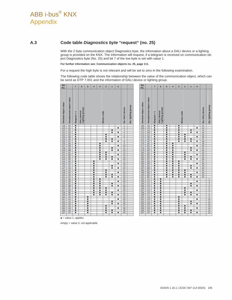
ABB i-bus® KNX Appendix
DGN/S 1.16.1 | 2CDC 507 114 D0201 155
A.3 Code table Diagnostics byte “request“ (no. 25)
With the 2 byte communication object Diagnostics byte, the information about a DALI device or a lighting group is provided on the KNX. The Information will request, if a telegram is received on communication ob-ject Diagnostics byte (No. 25) and bit 7 of the low byte is set with value 1. For further information see: Communication objects no. 25, page 111.
For a request the high byte is not relevant and will be set to zero in the following examination.
The following code table shows the relationship between the value of the communication object, which can be send as DTP 7.001 and the information of DALI device or lighting group.
BitNo. 7 6 5 4 3 2 1 0 Bit
No. 7 6 5 4 3 2 1 0
Dec
imal
obj
ect v
alue
Hex
adec
imal
obj
ect v
alue
Req
eust
= 1
DA
LI d
evic
e/
Ligh
ting
grou
ps
Bin
ary
code
No.
DA
LI d
evic
e
No.
ligh
ting
grou
p
Dec
imal
obj
ect v
alue
Hex
adec
imal
obj
ect v
alue
Req
uest
= 1
DA
LI d
evic
e/
Ligh
ting
grou
ps
Bin
ary
code
No.
DA
LI d
evic
e
No.
ligh
ting
grou
p
128 80 1 168 A8 41129 81 2 169 A9 42130 82 3 170 AA 43131 83 4 171 AB 44132 84 5 172 AC 45133 85 6 173 AD 46134 86 7 174 AE 47135 87 8 175 AF 48136 88 9 176 B0 49137 89 10 177 B1 50138 8A 11 178 B2 51139 8B 12 179 B3 52140 8C 13 180 B4 53141 8D 14 181 B5 54142 8E 15 182 B6 55143 8F 16 183 B7 56144 90 17 184 B8 57145 91 18 185 B9 58146 92 19 186 BA 59147 93 20 187 BB 60148 94 21 188 BC 61149 95 22 189 BD 62150 96 23 190 BE 63151 97 24 191 BF 64152 98 25 192 C0 1153 99 26 193 C1 2154 9A 27 194 C2 3155 9B 28 195 C3 4156 9C 29 196 C4 5157 9D 30 197 C5 6158 9E 31 198 C6 7159 9F 32 199 C7 8160 A0 33 200 C8 9161 A1 34 201 C9 10162 A2 35 202 CA 11163 A3 36 203 CB 12164 A4 37 204 CC 13165 A5 38 205 CD 14166 A6 39 206 CE 15167 A7 40 207 CF 16
= value 1, applies
empty = value 0, not applicable
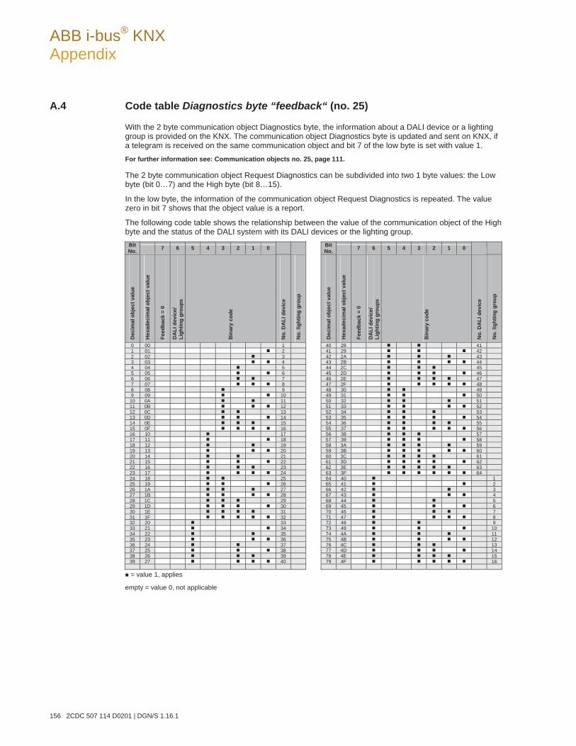
ABB i-bus® KNX Appendix
156 2CDC 507 114 D0201 | DGN/S 1.16.1
A.4 Code table Diagnostics byte “feedback“ (no. 25)
With the 2 byte communication object Diagnostics byte, the information about a DALI device or a lighting group is provided on the KNX. The communication object Diagnostics byte is updated and sent on KNX, if a telegram is received on the same communication object and bit 7 of the low byte is set with value 1. For further information see: Communication objects no. 25, page 111.
The 2 byte communication object Request Diagnostics can be subdivided into two 1 byte values: the Low byte (bit 0…7) and the High byte (bit 8…15).
In the low byte, the information of the communication object Request Diagnostics is repeated. The value zero in bit 7 shows that the object value is a report.
The following code table shows the relationship between the value of the communication object of the High byte and the status of the DALI system with its DALI devices or the lighting group.
BitNo. 7 6 5 4 3 2 1 0 Bit
No. 7 6 5 4 3 2 1 0
Dec
imal
obj
ect v
alue
Hex
adec
imal
obj
ect v
alue
Feed
back
= 0
DA
LI d
evic
e/
Ligh
ting
grou
ps
Bin
ary
code
No.
DA
LI d
evic
e
No.
ligh
ting
grou
p
Dec
imal
obj
ect v
alue
Hex
adec
imal
obj
ect v
alue
Feed
back
= 0
DA
LI d
evic
e/
Ligh
ting
grou
ps
Bin
ary
code
No.
DA
LI d
evic
e
No.
ligh
ting
grou
p
0 00 1 40 28 411 01 2 41 29 422 02 3 42 2A 433 03 4 43 2B 444 04 5 44 2C 455 05 6 45 2D 466 06 7 46 2E 477 07 8 47 2F 488 08 9 48 30 499 09 10 49 31 50
10 0A 11 50 32 5111 0B 12 51 33 5212 0C 13 52 34 5313 0D 14 53 35 5414 0E 15 54 36 5515 0F 16 55 37 5616 10 17 56 38 5717 11 18 57 39 5818 12 19 58 3A 5919 13 20 59 3B 6020 14 21 60 3C 6121 15 22 61 3D 6222 16 23 62 3E 6323 17 24 63 3F 6424 18 25 64 40 125 19 26 65 41 226 1A 27 66 42 327 1B 28 67 43 428 1C 29 68 44 529 1D 30 69 45 630 1E 31 70 46 731 1F 32 71 47 832 20 33 72 48 933 21 34 73 49 1034 22 35 74 4A 1135 23 36 75 4B 1236 24 37 76 4C 1337 25 38 77 4D 1438 26 39 78 4E 1539 27 40 79 4F 16
= value 1, applies
empty = value 0, not applicable
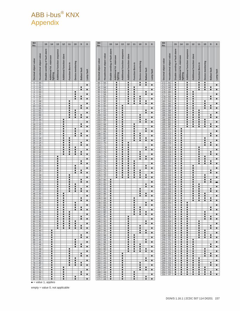
ABB i-bus® KNX Appendix
DGN/S 1.16.1 | 2CDC 507 114 D0201 157
BitNo. 15 14 13 12 11 10 9 8 Bit
No. 15 14 13 12 11 10 9 8 BitNo. 15 14 13 12 11 10 9 8
Dec
imal
obj
ect v
alue
Hex
adec
imal
obj
ect v
alue
Dis
able
sen
ding
of f
ault
alar
m
Add
ition
al fc
t. st
airc
ase
light
ing
Add
ition
al fu
nctio
n se
quen
ce
Add
ition
al fu
nctio
n sl
ave
Func
tion
Bur
n-in
Dev
ice
mon
itorin
g
Bal
last
faul
t
Lam
p fa
ult
Dec
imal
obj
ect v
alue
Hex
adec
imal
obj
ect v
alue
Dis
able
sen
ding
of f
ault
alar
m
Add
ition
al fc
t. st
airc
ase
light
ing
Add
ition
al fu
nctio
n se
quen
ce
Add
ition
al fu
nctio
n sl
ave
Func
tion
Bur
n-in
Dev
ice
mon
itorin
g
Bal
last
faul
t
Lam
p fa
ult
Dec
imal
obj
ect v
alue
Hex
adec
imal
obj
ect v
alue
Dis
able
sen
ding
of f
ault
alar
m
Add
ition
al fc
t. st
airc
ase
light
ing
Add
ition
al fu
nctio
n se
quen
ce
Add
ition
al fu
nctio
n sl
ave
Func
tion
Bur
n-in
Dev
ice
mon
itorin
g
Bal
last
faul
t
Lam
p fa
ult
0 00 86 56 172 AC 1 01 87 57 173 AD 2 02 88 58 174 AE 3 03 89 59 175 AF 4 04 90 5A 176 B0 5 05 91 5B 177 B1 6 06 92 5C 178 B2 7 07 93 5D 179 B3 8 08 94 5E 180 B4 9 09 95 5F 181 B5
10 0A 96 60 182 B6 11 0B 97 61 183 B7 12 0C 98 62 184 B8 13 0D 99 63 185 B9 14 0E 100 64 186 BA 15 0F 101 65 187 BB 16 10 102 66 188 BC 17 11 103 67 189 BD 18 12 104 68 190 BE 19 13 105 69 191 BF 20 14 106 6A 192 C0 21 15 107 6B 193 C1 22 16 108 6C 194 C2 23 17 109 6D 195 C3 24 18 110 6E 196 C4 25 19 111 6F 197 C5 26 1A 112 70 198 C6 27 1B 113 71 199 C7 28 1C 114 72 200 C8 29 1D 115 73 201 C9 30 1E 116 74 202 CA 31 1F 117 75 203 CB 32 20 118 76 204 CC 33 21 119 77 205 CD 34 22 120 78 206 CE 35 23 121 79 207 CF 36 24 122 7A 208 D0 37 25 123 7B 209 D1 38 26 124 7C 210 D2 39 27 125 7D 211 D3 40 28 126 7E 212 D4 41 29 127 7F 213 D5 42 2A 128 80 214 D6 43 2B 129 81 215 D7 44 2C 130 82 216 D8 45 2D 131 83 217 D9 46 2E 132 84 218 DA 47 2F 133 85 219 DB 48 30 134 86 220 DC 49 31 135 87 221 DD 50 32 136 88 222 DE 51 33 137 89 223 DF 52 34 138 8A 224 E0 53 35 139 8B 225 E1 54 36 140 8C 226 E2 55 37 141 8D 227 E3 56 38 142 8E 228 E4 57 39 143 8F 229 E5 58 3A 144 90 230 E6 59 3B 145 91 231 E7 60 3C 146 92 232 E8 61 3D 147 93 233 E9 62 3E 148 94 234 EA 63 3F 149 95 235 EB 64 40 150 96 236 EC 65 41 151 97 237 ED 66 42 152 98 238 EE 67 43 153 99 239 EF 68 44 154 9A 240 F0 69 45 155 9B 241 F1 70 46 156 9C 242 F2 71 47 157 9D 243 F3 72 48 158 9E 244 F4 73 49 159 9F 245 F5 74 4A 160 A0 246 F6 75 4B 161 A1 247 F7 76 4C 162 A2 248 F8 77 4D 163 A3 249 F9 78 4E 164 A4 250 FA 79 4F 165 A5 251 FB 80 50 166 A6 252 FC 81 51 167 A7 253 FD 82 52 168 A8 254 FE 83 53 169 A9 255 FF 84 54 170 AA 85 55 171 AB = value 1, applies
empty = value 0, not applicable
ABB i-bus® KNX Appendix
158 2CDC 507 114 D0201 | DGN/S 1.16.1
A.5 Further information about DALI
Further information about DALI and its possibilities in lighting technology can be found in our manuals:
DALI manual of the DALI AG which is part of the ZVEI:
This manual and further information about DALI can be found on the DALI AG Internet page under www.dali-ag.org.
ABB i-bus® KNX Appendix
DGN/S 1.16.1 | 2CDC 507 114 D0201 159
A.6 Scope of delivery
The ABB i-bus KNX DALI Gateway DGN/S 1.16.1 is supplied together with the following components. Please check the items received using the following list:
1 pc. DGN/S 1.16.1 MDRC
1 pc. Installation and operating instructions
1 pc. KNX bus connection terminal (red/black)
ABB i-bus® KNX Appendix
160 2CDC 507 114 D0201 | DGN/S 1.16.1
A.7 Ordering Information
Short description Description Order code bbn 40 16779 EAN
Price group
Weight 1 pcs [kg]
Pack unit [Pcs]
DGN/S 1.16.1 DALI Gateway, Emergency Lighting, MDRC, MW1) 4
2CDG 110 142 R0011 84556 4 P2 0.22 1
Other DALI Gateways in the ABB i-bus® range 2)
DLR/S 8.16.1M DALI Light Controller, MDRC, MW1) 6 2CDG 110 101 R0011 67656 4 P2 0.26 1
DG/S 1.16.1 DALI Gateway 16 Group, MDRC, MW1) 4
2CDG 110 103 R0011 66950 4 P2 0.22 1
DG/S 1.1 DALI Gateway, 1-fold, MDRC, MW1) 4 2CDG 110 026 R0011 58583 5 P2 0.22 1
DG/S 8.1 DALI Gateway, 8-fold, MDRC, MW1) 6 2CDG 110 025 R0011 58582 8 P2 0.31 1 1) MW = Module width 2) For compact function description see: ABB i-bus® DG/S in comparison, page 7
ABB i-bus® KNX Appendix
DGN/S 1.16.1 | 2CDC 507 114 D0201 161
A.8 DALI equipment
ABB provides a comprehensive range of DALI components.
Ballasts (electrical upstream devices) for fluorescent lamps, electronic transformers for low-voltage halo-gen lamps, dimmers, switch actuators, DALI LED converters etc. with DALI interfaces are available.
All DALI components and their technical properties are listed in the Low-voltage main catalogue Chap-ter 15: Lighting equipment.
More information can be found under the following address:
ABB STOTZ-KONTAKT/Striebel & John Vertriebsgesellschaft mbH (ASJ) Postfach 10 12 69 69002 Heidelberg Eppelheimer Straße 82 69123 Heidelberg E-mail: [email protected]
Phone: 01805 69 2002 (Germany only) Fax: 01805 69 3003 (Germany only)
ABB i-bus® KNX Appendix
162 2CDC 507 114 D0201 | DGN/S 1.16.1
A.9 Notes

Contact
ABB STOTZ-KONTAKT GmbH Eppelheimer Straße 82 69123 Heidelberg, Germany Phone: +49 (0)6221 701 607 Fax: +49 (0)6221 701 724 e-mail: [email protected]
Further information and local contacts: www.abb.com/knx
P
ublic
atio
n N
umbe
r 2C
DC
507
114
D01
01 (0
8.11
) Note:We reserve the right to make technical changes ormodify the contents of this document without prior notice. With regard to purchase orders, the agreed particulars shall prevail. ABB AG shall not be liable for any consequences arising from errors or incomplete information in this document. We reserve the rights to this document and in the subject matter and illustrations containedtherein. Any reproduction, disclosure to third partiesor utilization of its content – in whole or in parts – is forbidden without prior written consent of ABB AG. Copyright© 2010 ABB All rights reserved