ABB i-bus KNX Application Unit Time ABZ/S 2.1 Product … · General ABZ/S 2.1 | 2CDC 509 033 D0202...
257
A BB i-bus ® KNX A pplication Unit Time ABZ/S 2.1 Product Manual
Transcript of ABB i-bus KNX Application Unit Time ABZ/S 2.1 Product … · General ABZ/S 2.1 | 2CDC 509 033 D0202...

ABB i-bus® KNX Application Unit Time ABZ/S 2.1 Product Manual


ABZ/S, Application Unit Time
ABZ/S 2.1 | 2CDC 509 033 D0202 3
ABB i-bus KNX
Contents Page
1 General 6
1.1 Product and functional description........................................................7
2 Device technology 8
2.1 Technical data.......................................................................................8 2.2 Circuit diagram......................................................................................9 2.3 Dimension drawing .............................................................................10 2.4 Assembly and installation ...................................................................10
3 Commissioning 12
3.1 Overview.............................................................................................12 3.2 Parameterisation software (PZM 2.0).................................................13 3.3 Interface ..............................................................................................15 3.3.1 ABB – Times Groups/2 ....................................................................15 3.3.2 Title bar ............................................................................................15 3.3.3 Menu bar ..........................................................................................15 3.3.4 Status bar .........................................................................................15 3.3.5 File menu..........................................................................................16 3.3.5.1 Save...............................................................................................16 3.3.5.2 Export ............................................................................................17 3.3.5.3 Import.............................................................................................18 3.3.5.4 Print ...............................................................................................18 3.3.5.5 View page ......................................................................................19 3.3.5.6 Filter print data...............................................................................20 3.3.5.7 Printer setup ..................................................................................21 3.3.5.8 Close..............................................................................................21 3.3.6 Edit menu .........................................................................................22 3.3.6.1 New day routine.............................................................................22 3.3.6.2 Copy ..............................................................................................22 3.3.6.3 Insert..............................................................................................22 3.3.6.4 Delete ............................................................................................22 3.3.6.5 Usage ............................................................................................22 3.3.7 Online menu.....................................................................................23 3.3.7.1 Set date/time..................................................................................24 3.3.7.2 Show status ...................................................................................26 3.3.8 Window menu...................................................................................27 3.3.8.1 Split horizontal ...............................................................................27 3.3.8.2 Toolbar...........................................................................................27 3.3.8.3 Status bar ......................................................................................27 3.3.9 Help menu........................................................................................28 3.3.9.1 Help for device...............................................................................28 3.3.9.2 Help for application software .........................................................28 3.3.9.3 About... ..........................................................................................28 3.3.10 Toolbar .............................................................................................29 3.3.10.1 Copy ..............................................................................................29 3.3.10.2 Paste..............................................................................................29 3.3.10.3 Print ...............................................................................................29 3.3.10.4 Save...............................................................................................30 3.3.10.5 Help ...............................................................................................30 3.3.10.6 Close..............................................................................................30

ABZ/S, Application Unit Time
ABZ/S 2.1 | 2CDC 509 033 D0202 4
ABB i-bus KNX
3.3.10.7 Hotkey selection ............................................................................30 3.4 Parameters .........................................................................................31 3.4.1 General.............................................................................................31 3.4.1.1 Operating mode of clock................................................................36 3.4.2 Time switch program........................................................................44 3.4.3 Day routines - General .....................................................................45 3.4.3.1 Insert new day routines .................................................................46 3.4.3.2 Edit day routines............................................................................52 3.4.3.3 Delete day routines........................................................................56 3.4.4 Switching time - General ..................................................................58 3.4.4.1 Insert new switching time ..............................................................59 3.4.4.2 Edit switching time.........................................................................73 3.4.4.3 Delete switching time.....................................................................86 3.4.4.4 Copy/insert switching time.............................................................89 3.4.5 Week routine - General ....................................................................93 3.4.5.1 Insert new week routine.................................................................94 3.4.5.2 Edit week routine ...........................................................................96 3.4.5.3 Delete week routine.......................................................................98 3.4.6 Daylight saving times - General .....................................................100 3.4.6.1 Insert new daylight saving time ...................................................101 3.4.6.2 Edit daylight saving time..............................................................105 3.4.6.3 Delete daylight saving time..........................................................107 3.4.7 Special days - General...................................................................109 3.4.7.1 Insert new special day .................................................................110 3.4.7.2 Edit special day............................................................................113 3.4.7.3 Delete special day .......................................................................115 3.4.7.4 Overlapping of periods ................................................................117 3.4.8 Overview - General ........................................................................118 3.4.8.1 Display overview..........................................................................119 3.4.9 Groups - General ...........................................................................122 3.4.9.1 Insert new group..........................................................................123 3.4.9.2 Edit group ....................................................................................140 3.4.9.3 Modify group ................................................................................157 3.4.10 Group trigger - General ..................................................................174 3.4.10.1 Insert new group trigger...............................................................175 3.4.10.2 Edit group trigger .........................................................................180 3.4.10.3 Delete group trigger.....................................................................184 3.4.11 Group members - General .............................................................186 3.4.11.1 Insert new group member............................................................187 3.4.11.2 Edit group members ....................................................................200 3.4.11.3 Delete group member..................................................................212 3.4.12 Group addresses - General............................................................215 3.4.12.1 Insert new group address ............................................................216 3.4.12.2 Edit group address.......................................................................222 3.4.12.3 Delete group address ..................................................................229 3.4.12.4 Rename group address ...............................................................233 3.4.12.5 Assign group address..................................................................235 3.4.13 Utilisation........................................................................................242 3.5 Communication objects 250 to 253 ..................................................243
4 Planning and application 244
4.1 Context-sensitive “Help” file..............................................................244 4.2 Behaviour on bus voltage failure ......................................................245 4.3 Behaviour after bus voltage recovery ...............................................245
Appendix VII
A.1 Scope of supply ................................................................................. VII

ABZ/S, Application Unit Time
ABZ/S 2.1 | 2CDC 509 033 D0202 5
ABB i-bus KNX
A.2 List of diagrams................................................................................. VIII A.3 List of tables....................................................................................... XII A.4 List of key words ............................................................................... XIII A.5 Ordering information .........................................................................XIV A.6 Notes..................................................................................................XV

General
ABZ/S 2.1 | 2CDC 509 033 D0202 6
ABB i-bus KNX
1 General
Complex timer operations and time controllers are becoming increasingly important in modern buildings with ABB i-bus® KNX. Time-controlled day or week routines e.g. of lighting installations should be implemented in buildings, factories or hotels. In schools, the lighting should e.g. be switched off at the weekend for energy reasons or the heating system should be lowered to a minimum using time control. In hotels, it should be possible to set different lighting or ventilation sequences for different events. In underground car parks for example, different time sequences should apply on different days of the week. Even year time switch programs and group formation should be implemented in continually recurring processes.
All the previously described applications can be parameterised using the Application Unit Time.
This manual provides you with detailed technical information about the Application Unit Time including its installation and programming and explains its application using examples.
The manual is divided into the following chapters:
Chapter 1 General
Chapter 2 Device technology
Chapter 3 Commissioning
Chapter 4 Planning and application
Appendix

General
ABZ/S 2.1 | 2CDC 509 033 D0202 7
ABB i-bus KNX
1.1 Product and functional description
The Application Unit Time ABZ/S 2.1 is a DIN rail mounted device for insertion in the distribution board. The connection to the bus is carried out via a bus connecting terminal at the front of the device. Both the assignment of the physical address and the setting of parameters are carried out with ETS3 from version V1.0.
The device is supplied via the ABB i-bus® and does not require an additional power supply.
The processing is carried out in the application program Times Groups/2.
The device is characterised by its comprehensive and clear functionality which enables its use in a wide variety of applications. The following list provides an overview:
Multi-channel time switch with
- year time switch program, week routine and day routine
- input of daylight saving times and special days
Recording of groups

Device technology
ABZ/S 2.1 | 2CDC 509 033 D0202 8
ABB i-bus KNX
2 Device technology
The Application Unit Time is a DIN rail mounted device for insertion in the distribution board. The device contains a year time switch program with the option of defining day routines and week routines individually. Complex group formations are also possible.
The device is ready for operation after connecting the bus voltage. The Application Unit Time is parameterised via ETS3. The connection to the bus is established via the bus connecting terminal at the front of the device.
Fig. 1: ABZ/S 2.1
2.1 Technical data
Power supply - Bus voltage 21 … 32V DC
- Power consumption, bus < 12mA
- Leakage loss, bus Max. 250mW
Connections - KNX Via bus connecting terminal
Operating and display elements - Programming LED (3) For assignment of the physical address
- Programming button (2) For assignment of the physical address
Type of protection - IP 20 In accordance with DIN EN 60 529
Protection class - II In accordance with DIN EN 61 140
Insulation category Overvoltage category III in accordance with DIN EN 60 664-1
Degree of pollution 2 in accordance with DIN EN 60 664-1
KNX safety extra-low voltage SELV 24 V DC Temperature range - Operation
- Storage - Transport
- 5°C...+45°C -25°C...+ 55°C -25°C...+ 70°C
Ambient conditions - Maximum air humidity 93%, moisture condensation not permitted
Design - DIN rail mounted device (MDRC) Modular installation device, ProM
- Dimensions 90 x 36 x 64.5mm (H x W x D)
- Mounting width in modules 2.2 modules at 18mm
- Mounting depth 64.5mm
Installation - On 35mm mounting rail In accordance with DIN EN 60 715
Mounting position - As required
Weight - 0.1kg
Housing/colour - Plastic housing, grey
Certification - KNX in accordance with EN 50 090-1, -2 Certificate
CE norm - In accordance with the EMC and low voltage guidelines
Table 1: Technical data
2C
DC
071
280
F0
005
Device technology
ABZ/S 2.1 | 2CDC 509 033 D0202 9
ABB i-bus KNX
Device type Application program Maximum number of communication objects
Maximum number of group addresses
Maximum number of associations
ABZ/S 2.1 Times Groups/…* 250 250 254
* … = current version number of the application program
Table 2: Application program
Note: The ETS and the current version of the device application program are required for programming.
The current version of the application program is available for download on the Internet at www.abb.com/knx. After import it is available in the ETS under ABB/Controller/Controller.
The device does not support the closing function of a KNX device in the ETS. If you inhibit access to all devices of the project with a BCU code, it has no effect on this device. Data can still be read and programmed.
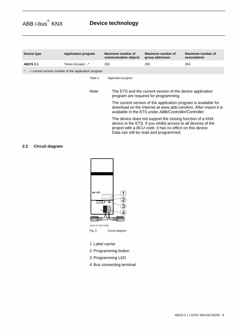
2.2 Circuit diagram
2CDC 072 053 F0005
Fig. 2: Circuit diagram
1 Label carrier
2 Programming button
3 Programming LED
4 Bus connecting terminal

Device technology
ABZ/S 2.1 | 2CDC 509 033 D0202 10
ABB i-bus KNX
2.3 Dimension drawing
2CDC 072 051 F0006
Fig. 3: Dimension drawing
2.4 Assembly and installation
The Application Unit Time is a DIN rail mounted device for insertion in distribution boards for snap-on mounting on 35mm mounting rails, in accordance with DIN EN 60 715.
The connection to the bus is carried out via the bus connecting terminal supplied.
The device is ready for operation once the bus voltage has been applied.
The accessibility of the devices for operation, testing, inspection, maintenance and repair must be ensured (according to DIN VDE 0100-520).
Commissioning requirements
To put the Application Unit Time into operation, a PC with ETS3 and an interface connection to the ABB i-bus®, e.g. via an RS232 interface or a USB interface are required. The device is ready for operation once the bus voltage has been applied.
The installation and commissioning may only be carried out by specialist electricians. When planning and setting up electrical installations, the relevant norms, guidelines, standards and specifications must be observed.
- Protect the device against damp, dirt and damage during transportation, storage and operation.
- Only operate the device within the specified technical data!
- Only operate the device in an enclosed housing (distribution board)!

Device technology
ABZ/S 2.1 | 2CDC 509 033 D0202 11
ABB i-bus KNX
Supplied state
The Application Unit Time is supplied with the physical address 15.15.255. The application program is pre-loaded. During the commissioning stage, only group addresses and parameters need to be loaded. If required, the complete application program can be reloaded. When changing the application program or after unloading, a longer download process may occur.
Download behaviour
Due to the complexity of the device, it can take up to 1.5 min. during a download until the progress bar appears, depending on the computer being used.
Assignment of the physical address
The assignment and programming of the physical address, group address and parameters is carried out in ETS.
Cleaning
Dirty devices can be cleaned with a dry cloth. If this is not sufficient, a cloth that has been moistened with soap may be used. Corrosive cleaning agents or solvents may not be used in any event.
Maintenance
The device is maintenance-free. In the event of damage (e.g. during transportation, storage), repairs may not be carried out by a third party. The right to claim under guarantee expires when the device is opened.

Commissioning
ABZ/S 2.1 | 2CDC 509 033 D0202 12
ABB i-bus KNX
3 Commissioning
3.1 Overview
The application program “Times Groups/2” is available for the Application Unit Time. Programming requires ETS3. A maximum of 250 communication objects, 250 group addresses and 254 associations can be linked.
The following functions are available:
Time switch program Defines when telegrams with specific group addresses and values are sent on the bus.
Day routines Contains the time program of a day from 00:00 to 23:59. Day routines can be activated and deactivated by the time switch program and by telegrams. There are 15 day routines available.
Switching times Up to 800 switching times can be assigned to the day routines.
Week routine Defines the assignment of day routines to the days of the week. There is one week routine available.
Special days Special days denote individual days or time intervals which deviate from the standard week routine. There are 100 special days available.
Daylight saving times Automatic calculation of the daylight saving times. A total of 10 consecutive years can be calculated.
Group A combination of group addresses which are sent at the same time. There are 30 groups available.
Group members Group addresses which belong to a group. There are 300 group members available.
Group triggers Group addresses which trigger a group. The type and value of the group address determine the triggering of the group e.g.:
“0” switches ON,
“1” switches OFF,
“Value < 230” switches ON,
“Value > 250” switches OFF. Table 3: Functions of the application program
Commissioning
ABZ/S 2.1 | 2CDC 509 033 D0202 13
ABB i-bus KNX
3.2 Parameterisation software (PZM 2.0)
The parameterisation software “PZM 2.0” is used by the system operator and offers the following options:
- loading the installation configuration which has been created in ETS into the ABZ/S 2.1.
- modifying the time switch program and then downloading the program to the ABZ/S 2.1
- saving of the modified time switch program
- reading out and setting the time and date of the ABZ/S 2.1
- reading out the status information of the ABZ/S 2.1.
Note: The parameterisation software PZM 2.0 has its own manual which can be downloaded from the Internet.

Commissioning
ABZ/S 2.1 | 2CDC 509 033 D0202 14
ABB i-bus KNX
Parameterising the ABZ/S 2.1 with ETS
A comment for the system operator should be entered in the “Description” field in the ETS3 “Properties” window e.g. project name, function of the Application Unit Time in the installation and the date.
Fig. 4: ETS3 “General” dialog window
Note: This information is displayed in the table area of the parameterisation software PZM 2.0 as “Comment of the installer” after loading the time switch program.

Commissioning
ABZ/S 2.1 | 2CDC 509 033 D0202 15
ABB i-bus KNX
3.3 Interface
3.3.1 ABB – Times Groups/2
Fig. 5: “Times Groups/2” screen
3.3.2 Title bar
Fig. 6: “Title bar” screen
The title bar contains information about the manufacturer, the name of the application program, the physical address as well as the type and the name of the device.
3.3.3 Menu bar
Fig. 7: “Menu bar” screen
The File, Edit, Online, Window and Help menus are visible in the menu bar.
3.3.4 Status bar
Fig. 8: “Status bar” screen
The status bar can be activated or deactivated in the Window menu, under the Status bar menu item.
If it is activated, it always forms the lower border of the parameter window. It indicates for the current selection in the table area the number of available elements for further entries.

Commissioning
ABZ/S 2.1 | 2CDC 509 033 D0202 16
ABB i-bus KNX
3.3.5 File menu
Fig. 9: “File” menu
Some menu items are context-sensitive and are only activated for specific configurations. Inactive menu items are greyed out.
3.3.5.1 Save
The parameter data is stored in the ETS3 database by selecting the Save menu item.
Commissioning
ABZ/S 2.1 | 2CDC 509 033 D0202 17
ABB i-bus KNX
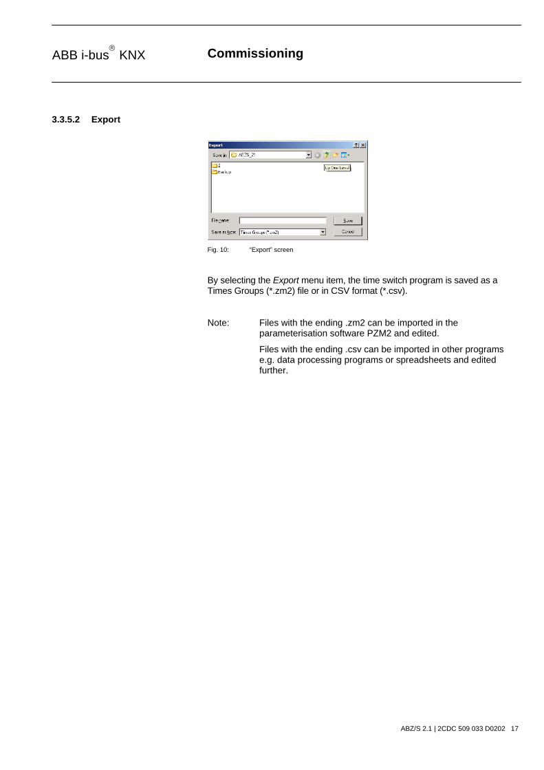
3.3.5.2 Export
Fig. 10: “Export” screen
By selecting the Export menu item, the time switch program is saved as a Times Groups (*.zm2) file or in CSV format (*.csv).
Note: Files with the ending .zm2 can be imported in the parameterisation software PZM2 and edited.
Files with the ending .csv can be imported in other programs e.g. data processing programs or spreadsheets and edited further.

Commissioning
ABZ/S 2.1 | 2CDC 509 033 D0202 18
ABB i-bus KNX
3.3.5.3 Import
Fig. 11: “Import” screen
By selecting the Import menu item, the time switch program which has been exported from the application program or the parameterisation software PZM2 is read in as a .zm2 file.
Note: Older .zm1 files can be imported in the Application Unit Time ABZ/S 2.1 and edited.
When importing a zm2 file into an existing ETS3 project, the parameters that were saved in the edited project are overwritten.
When importing the .zm2 file, note that changes have possibly been carried out to the time switch program since exporting the file.
It is strongly recommended that you back up the data in the ETS3 project before each import.
3.3.5.4 Print
By selecting the Print menu item, parameter settings are printed out in tabular form.
Commissioning
ABZ/S 2.1 | 2CDC 509 033 D0202 19
ABB i-bus KNX
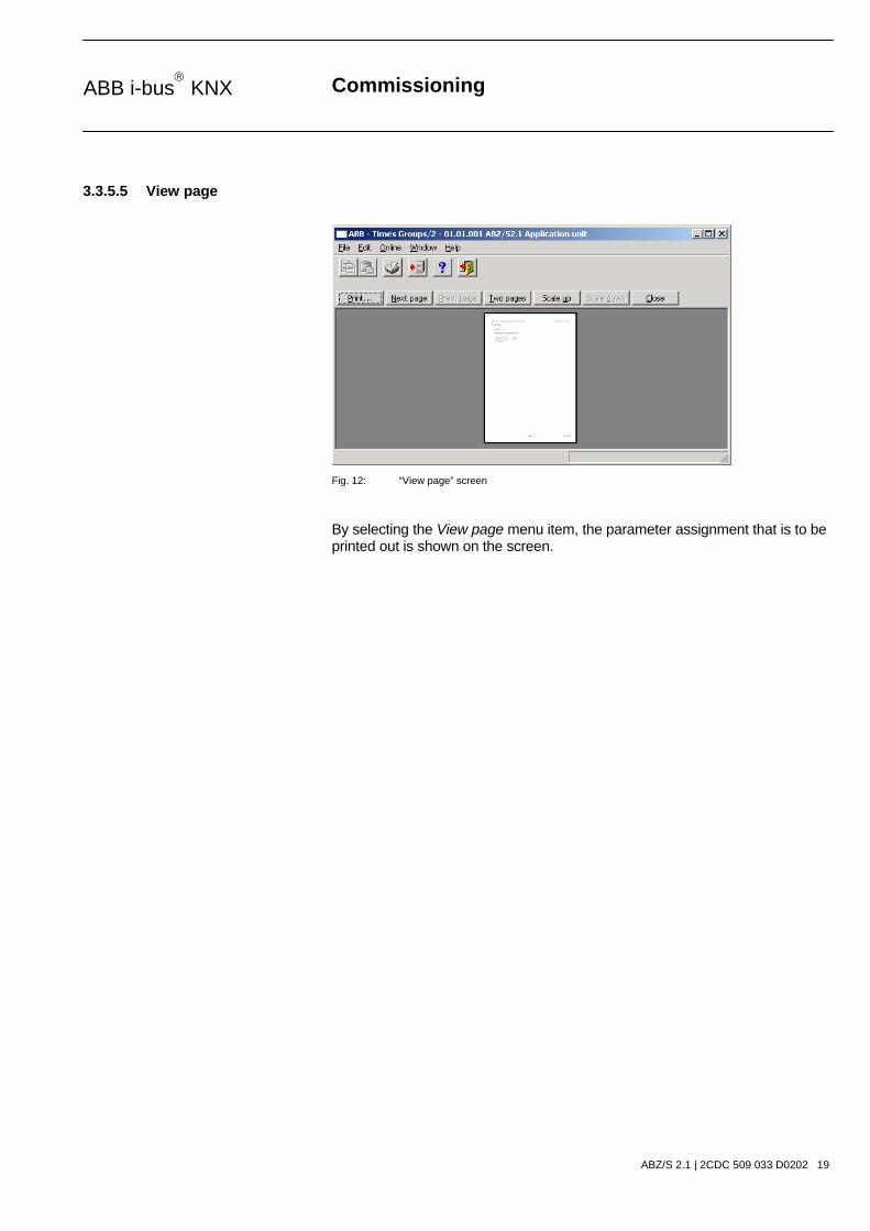
3.3.5.5 View page
Fig. 12: “View page” screen
By selecting the View page menu item, the parameter assignment that is to be printed out is shown on the screen.

Commissioning
ABZ/S 2.1 | 2CDC 509 033 D0202 20
ABB i-bus KNX
3.3.5.6 Filter print data
Fig. 13: “Filter print data” screen
By selecting the menu item Filter print data, those parts of the parameter assignment which should be printed out are selected.
Type
Options: All/ Selection
Option All = The entire configuration is printed out.
Option Selection = Only certain parts of the configuration are printed out. Select the entries which should be printed out with the left mouse button, while holding down the Control button [Ctrl].
“OK” button
When the “OK” button is pressed, the settings are adopted and the parameter window closes.
“Cancel” button
When the “Cancel” button is pressed, the function is aborted and the parameter window closes.
“Help” button
The “Help” file can be opened directly via the “Help” button and a further parameter window Help for application program… is opened.

Commissioning
ABZ/S 2.1 | 2CDC 509 033 D0202 21
ABB i-bus KNX
3.3.5.7 Printer setup
You can select and set up a printer by selecting the menu item Printer setup.
3.3.5.8 Close
The application program is closed by selecting the Close menu item. You then return to the Properties dialog window in ETS3. You are asked to save the data if necessary.
Hotkey: Alt+F4
Commissioning
ABZ/S 2.1 | 2CDC 509 033 D0202 22
ABB i-bus KNX
3.3.6 Edit menu
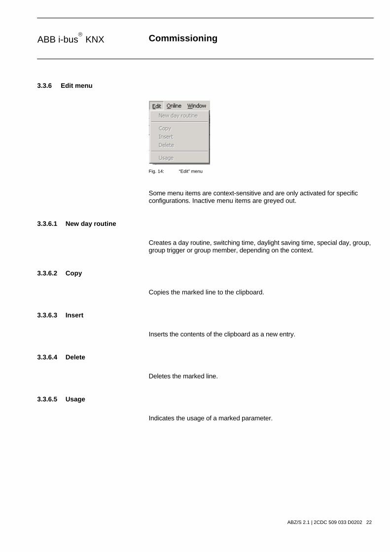
Fig. 14: “Edit” menu
Some menu items are context-sensitive and are only activated for specific configurations. Inactive menu items are greyed out.
3.3.6.1 New day routine
Creates a day routine, switching time, daylight saving time, special day, group, group trigger or group member, depending on the context.
3.3.6.2 Copy
Copies the marked line to the clipboard.
3.3.6.3 Insert
Inserts the contents of the clipboard as a new entry.
3.3.6.4 Delete
Deletes the marked line.
3.3.6.5 Usage
Indicates the usage of a marked parameter.

Commissioning
ABZ/S 2.1 | 2CDC 509 033 D0202 23
ABB i-bus KNX
3.3.7 Online menu
Fig. 15: “Online” menu
Some menu items are context-sensitive and are only activated for specific configurations. Inactive menu items are greyed out.

Commissioning
ABZ/S 2.1 | 2CDC 509 033 D0202 24
ABB i-bus KNX
3.3.7.1 Set date/time
When selecting the menu item Set date/time…, the date and time of the internal clock are read from the Application Unit Time or set.
The prerequisite is that the physical address and the application program of the Application Unit Time ABZ/S 2.1 must have been loaded beforehand.
After selecting the menu item Set date/time…, the associated dialog window opens.
Fig. 16: Parameter window: “Online menu, Set date/time”
Date
Options: Enter date
The date can be set in a range between 1.1.2000 and 31.12. 2035. It is displayed as numbers which are separated by full stops in the sequence day.month.year. On the right-hand side of the input field for the date, there is a button which is used to display the relevant calendar for the current date.
Note: When opening the dialog field, the current date of the PC is automatically read and displayed.
Time
Options: Enter time
The time is shown in hours, minutes and seconds. The displays for hours, minutes and seconds can be edited separately via the Left arrow and Right arrow buttons.
Note: When opening the dialog field, the current time of the PC is automatically read and displayed.

Commissioning
ABZ/S 2.1 | 2CDC 509 033 D0202 25
ABB i-bus KNX
“Read PC time” button, “Read ABZ/S time” button
The Date and Time fields can be updated with the corresponding time via the buttons Read PC time and Read ABZ/S time.
“Write ABZ/S time” button
The date and time can also be set via the Write ABZ/S time button.
Note: The time switch program is updated by adjusting the clock. Switching operations can be triggered as a result.
Adjust clock
Options: -255…0…+255
The accuracy of the internal clock is dependent in particular on the ambient temperature and can be up to +/– 1 min per month. By entering a correction value in the text field Adjust clock, the accuracy of the internal clock is improved. If the clock gains e.g. 20 seconds a month, this inaccuracy can be compensated by entering a correction value of “20” which corresponds to 20 seconds.
“Close” button
When the “Close” button is pressed, the function is closed and the parameter window Set time/date closes.
“Help” button
The “Help” file can be opened directly via the “Help” button and a further parameter window Help for application program… is opened.
Commissioning
ABZ/S 2.1 | 2CDC 509 033 D0202 26
ABB i-bus KNX
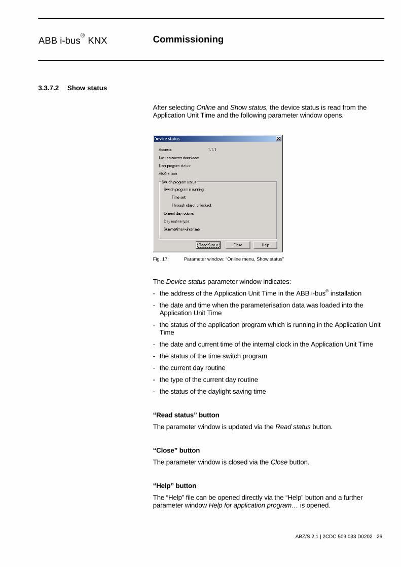
3.3.7.2 Show status
After selecting Online and Show status, the device status is read from the Application Unit Time and the following parameter window opens.
Fig. 17: Parameter window: “Online menu, Show status”
The Device status parameter window indicates:
- the address of the Application Unit Time in the ABB i-bus® installation
- the date and time when the parameterisation data was loaded into the Application Unit Time
- the status of the application program which is running in the Application Unit Time
- the date and current time of the internal clock in the Application Unit Time
- the status of the time switch program
- the current day routine
- the type of the current day routine
- the status of the daylight saving time
“Read status” button
The parameter window is updated via the Read status button.
“Close” button
The parameter window is closed via the Close button.
“Help” button
The “Help” file can be opened directly via the “Help” button and a further parameter window Help for application program… is opened.
Commissioning
ABZ/S 2.1 | 2CDC 509 033 D0202 27
ABB i-bus KNX
3.3.8 Window menu
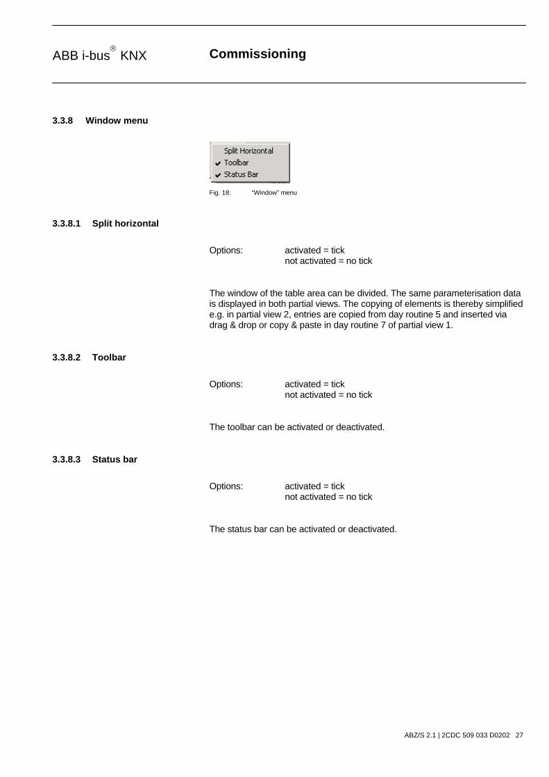
Fig. 18: “Window” menu
3.3.8.1 Split horizontal
Options: activated = tick not activated = no tick
The window of the table area can be divided. The same parameterisation data is displayed in both partial views. The copying of elements is thereby simplified e.g. in partial view 2, entries are copied from day routine 5 and inserted via drag & drop or copy & paste in day routine 7 of partial view 1.
3.3.8.2 Toolbar
Options: activated = tick not activated = no tick
The toolbar can be activated or deactivated.
3.3.8.3 Status bar
Options: activated = tick not activated = no tick
The status bar can be activated or deactivated.

Commissioning
ABZ/S 2.1 | 2CDC 509 033 D0202 28
ABB i-bus KNX
3.3.9 Help menu
Fig. 19: “Help” menu
3.3.9.1 Help for device
By selecting the menu item Help for device, brief information about the hardware of the Application Unit Time is displayed.
3.3.9.2 Help for application software
An extensive “Help” file appears after selecting the menu item Help for application software.
Hotkey: F1
3.3.9.3 About...
Fig. 20: “About…”
Information about the application program and the manufacturer of the device is displayed by selecting the About... menu item.
“OK” button
When the “OK” button is pressed, the settings are adopted and the parameter window closes.
“Help” button
The “Help” file can be opened directly via the “Help” button and a further parameter window Help for application program… is opened.

Commissioning
ABZ/S 2.1 | 2CDC 509 033 D0202 29
ABB i-bus KNX
3.3.10 Toolbar
Fig. 21: “Toolbar” screen
The toolbar contains buttons with the most important commands. The buttons are context-sensitive and are only activated for specific configurations.
The toolbar can be activated or deactivated in the Window menu under the Toolbar menu item.
3.3.10.1 Copy
Fig. 22: “Copy” symbol
Copies the marked line to the clipboard.
3.3.10.2 Paste
Fig. 23: “Paste” symbol
Inserts the contents of the clipboard as a new line.
3.3.10.3 Print
Fig. 24: “Print” symbol
Prints the parameter data in tabular form.

Commissioning
ABZ/S 2.1 | 2CDC 509 033 D0202 30
ABB i-bus KNX
3.3.10.4 Save
Fig. 25: “Save” symbol
Saves the parameter data in ETS3.
3.3.10.5 Help
Fig. 26: “Help” symbol
Opens the “Help” file of the application program.
Hotkey: F1
3.3.10.6 Close
Fig. 27: “Close” symbol
Closes the application program. Asks if you wish to save the data, if necessary.
3.3.10.7 Hotkey selection
Alt + F4 Close
F1 Help

Commissioning
ABZ/S 2.1 | 2CDC 509 033 D0202 31
ABB i-bus KNX
3.4 Parameters
3.4.1 General
Fig. 28: Parameter window: “General”
The general parameters are shown in the right-hand window.
Inactive time (mm:ss)
Options: (mm) 00…59 (ss) 00…59
This parameter sets the Inactive time on bus voltage recovery and during a download. During this period, no telegrams are sent and any received telegrams are not evaluated. The displays for minutes and seconds can be edited separately via the Left arrow and Right arrow buttons.
Min. telegram interval
Options: normal / 0.1 s / 0.2 s / 0.3 s / 0.4 s / 0.5 s
The parameter Min. telegram interval sets at which minimum intervals the Application Unit Time should send telegrams in sequence.
The option normal means that no delay is inserted.
An example:
If a Min. telegram interval of 0.5 s is set and 5 telegrams should be sent, the last telegram is sent 2.5 s after the first telegram.
Commissioning
ABZ/S 2.1 | 2CDC 509 033 D0202 32
ABB i-bus KNX
Time program
Options: none / new group address
It can be set with this parameter whether the time program is locked or unlocked via a group address.
Option none = Time program cannot be locked or unlocked.
Option new group address = Time program can be locked or unlocked via a newly created group address.

Commissioning
ABZ/S 2.1 | 2CDC 509 033 D0202 33
ABB i-bus KNX
After selecting the option new group address, the associated dialog window Add group addresses is activated.
Fig. 29: Dialog window: “Time program, Add group addresses”
The main group, middle group and the subgroup are created in sequence via drag & drop.
Fig. 30: Parameter window: “Time program, Create new main group, middle group and subgroup”
Note: The function descriptions and screenshots of the application program in this product manual all relate to ETS3. The application program for ETS4 has now become available.
The only difference between both program versions is the number of possible main groups: ETS3 = up to 15 main groups ETS4 = up to 31 main groups

Commissioning
ABZ/S 2.1 | 2CDC 509 033 D0202 34
ABB i-bus KNX
Fig. 31: Dialog window: “Time program, Main group, middle group and subgroup created”
By marking New middle group in the left-hand window, the newly created group address is visible in the right-hand window.
Fig. 32: Dialog window: “Time program, Middle group marked”
The Accept button is activated by clicking on the group address in the right-hand window.
Fig. 33: Dialog window: “Time program, Subgroup marked”
The new group address is adopted in the following way:
- by double-clicking on the active group address or - by pressing the right mouse button and selecting Accept in the pop-up menu or - by pressing the Accept button.
Commissioning
ABZ/S 2.1 | 2CDC 509 033 D0202 35
ABB i-bus KNX
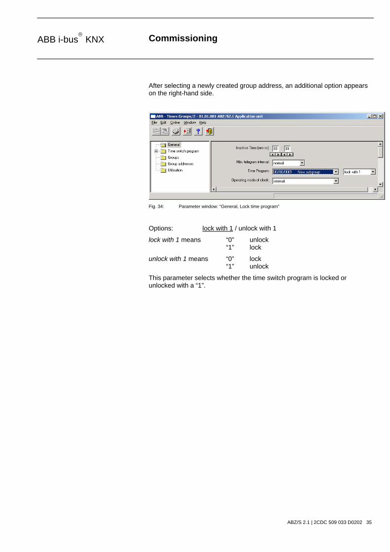
After selecting a newly created group address, an additional option appears on the right-hand side.
Fig. 34: Parameter window: “General, Lock time program”
Options: lock with 1 / unlock with 1
lock with 1 means “0” unlock “1” lock
unlock with 1 means “0” lock “1” unlock
This parameter selects whether the time switch program is locked or unlocked with a “1”.

Commissioning
ABZ/S 2.1 | 2CDC 509 033 D0202 36
ABB i-bus KNX
3.4.1.1 Operating mode of clock
Fig. 35: Parameter window: “General, Operating mode of clock”
Operating mode of clock
Options: internal/ Slave (always receive)/ Slave disable time (00:05 ... 23:55 receive)/ Master (send every minute)/ Master (send hourly)/ Master (send daily)
How does the internal clock work?
In the Application Unit Time, an internal clock controls the time switch program. The clock is supplied with bus voltage. In the event of a bus voltage failure, the internal clock has a power reserve of at least 1 h. In the event of a bus voltage recovery within the reserve period, the time switch program starts again automatically. Once the power reserve has elapsed, the current date and time are lost and the time switch program is stopped until the date and time are reset.
The clock can be set automatically through a telegram from a master clock or the clock must be set via the application program or using the parameterisation software PZM2.
The time switch program is updated by adjusting the clock. Switching operations can be triggered as a result.

Commissioning
ABZ/S 2.1 | 2CDC 509 033 D0202 37
ABB i-bus KNX
If the time switch program should start automatically after a bus failure, the clock must be operated as a slave and a group address should be assigned to the parameter Group address for request which then requests the sending of the current time by a master clock.
Once the power reserve has elapsed, a cold start is carried out in which the assigned group address is sent and the current time is requested. The internal clock is then synchronised with the master clock and the time switch program is updated and restarts.
The time switch program is updated by adjusting the clock. Switching operations can be triggered as a result.
Option: Internal
With the Internal option, it is not possible to set the date and time on the bus or to send telegrams from the bus.

Commissioning
ABZ/S 2.1 | 2CDC 509 033 D0202 38
ABB i-bus KNX
If the option Slave (always receive), Slave disable time (00:05 ... 23:55 receive), Master (send every minute), Master (send hourly) or Master (send daily) is selected, the following parameters are visible.
Fig. 36: Parameter window: “General, Operating mode of clock, Slave (always receive)”
Group address for time / date / request
Options: none / new group address
If slave or master is selected as the operating mode, the group addresses for the time and date and for requesting the time and date appear – if group addresses have already been assigned in ETS3. If no group addresses have yet been assigned in ETS3 or no new group addresses have yet been created, the options are preset with none.

Commissioning
ABZ/S 2.1 | 2CDC 509 033 D0202 39
ABB i-bus KNX
After selecting the option new group address, the associated dialog window Add group addresses is activated.
Fig. 37: Dialog window: “Operating mode of clock, Add group addresses”
The main group, middle group and the subgroup are created in sequence via drag & drop.
Fig. 38: Parameter window: “Operating mode of clock, Create new main group, middle group and subgroup”
Note: The function descriptions and screenshots of the application program in this product manual all relate to ETS3. The application program for ETS4 has now become available.
The only difference between both program versions is the number of possible main groups: ETS3 = up to 15 main groups ETS4 = up to 31 main groups
Commissioning
ABZ/S 2.1 | 2CDC 509 033 D0202 40
ABB i-bus KNX
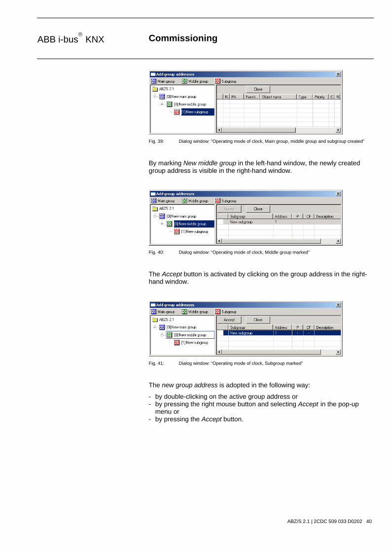
Fig. 39: Dialog window: “Operating mode of clock, Main group, middle group and subgroup created”
By marking New middle group in the left-hand window, the newly created group address is visible in the right-hand window.
Fig. 40: Dialog window: “Operating mode of clock, Middle group marked”
The Accept button is activated by clicking on the group address in the right-hand window.
Fig. 41: Dialog window: “Operating mode of clock, Subgroup marked”
The new group address is adopted in the following way:
- by double-clicking on the active group address or - by pressing the right mouse button and selecting Accept in the pop-up menu or - by pressing the Accept button.

Commissioning
ABZ/S 2.1 | 2CDC 509 033 D0202 41
ABB i-bus KNX
Option: Slave (always receive)
The internal clock can be set or synchronised via a telegram e.g. from a master clock.
Option: Slave disable time (00:05 ... 23:55 receive)
The internal clock can be set and synchronised via a telegram e.g. from a master clock between 00:05 and 23:55. Date and time telegrams are ignored in the period between 23:55 and 00:05. It is thus possible to avoid synchronisation problems when the day changes.
Option: Master (send every minute)
The internal clock sends telegrams with the time and date once per minute e.g. to synchronise other EIB devices. The time and date can be queried via communication object no. 250 “Request object”.
If a group address has been assigned to the parameter Group address for request, the current time and date can be requested from a master clock at any time.
If the internal clock is programmed as a master, it sends telegrams with the new time and date on the bus, once the time has been set with the help of the application program.
The time switch program is updated by adjusting the clock. Switching operations can be triggered as a result.

Commissioning
ABZ/S 2.1 | 2CDC 509 033 D0202 42
ABB i-bus KNX
Option: Master (send hourly)
Fig. 42: Parameter window: “General, Operating mode of clock, Master (send hourly)”
The internal clock sends telegrams with the time and date once per hour e.g. to synchronise other EIB devices. You are requested to enter a time (minute) for sending. The time and date can be queried via communication object no. 250 “Request object”.
If a group address has been assigned to the parameter Group address for request, the current time and date can be requested from a master clock at any time.
If the internal clock is programmed as a master, it sends telegrams with the new time and date on the bus, once the time has been set with the help of the application program.
The time switch program is updated by adjusting the clock. Switching operations can be triggered as a result.
A further parameter appears in the selection Master (send hourly).
Send at
Options: Minute 00…59 Hour not active
The minute for each full hour is entered with this parameter. The displays for minutes can be edited via the buttons Left arrow and Right arrow.

Commissioning
ABZ/S 2.1 | 2CDC 509 033 D0202 43
ABB i-bus KNX
Option: Master (send daily)
Fig. 43: Parameter window: “General, Operating mode of clock, Master (send daily)”
The internal clock sends telegrams with the time and date once per day e.g. to synchronise other EIB devices. You are requested to enter a time (hour, minute) for sending. The time and date can be queried via communication object no. 250 “Request object”.
If a group address has been assigned to the parameter Group address for request, the current time and date can be requested from a master clock at any time.
If the internal clock is programmed as a master, it sends telegrams with the new time and date on the bus, once the time has been set with the help of the application program.
The time switch program is updated by adjusting the clock. Switching operations can be triggered as a result.
Further parameters appear in the selection Master (send daily).
Send at
Options: Minute 00…59 Hour 00…23
The minute and the hour can be entered with this parameter. The displays for hours and minutes can be edited separately via the buttons Left arrow and Right arrow.
Commissioning
ABZ/S 2.1 | 2CDC 509 033 D0202 44
ABB i-bus KNX
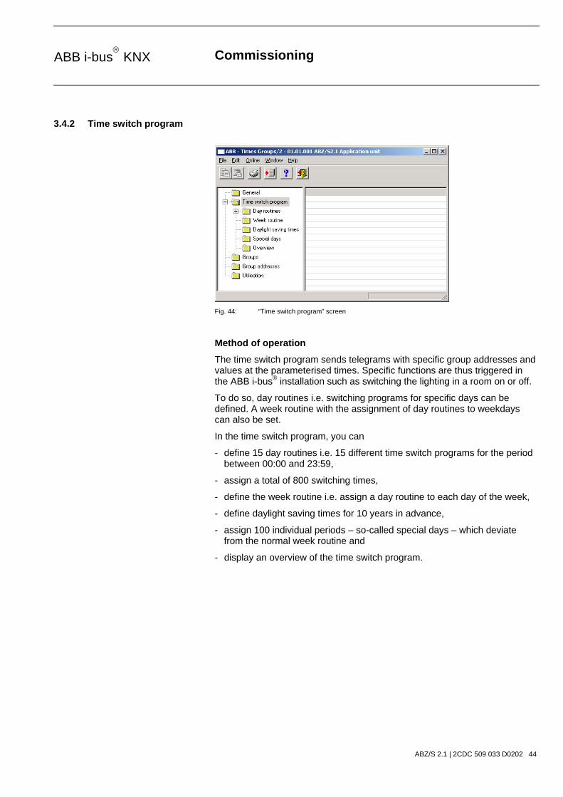
3.4.2 Time switch program
Fig. 44: “Time switch program” screen
Method of operation
The time switch program sends telegrams with specific group addresses and values at the parameterised times. Specific functions are thus triggered in the ABB i-bus® installation such as switching the lighting in a room on or off.
To do so, day routines i.e. switching programs for specific days can be defined. A week routine with the assignment of day routines to weekdays can also be set.
In the time switch program, you can
- define 15 day routines i.e. 15 different time switch programs for the period between 00:00 and 23:59,
- assign a total of 800 switching times,
- define the week routine i.e. assign a day routine to each day of the week,
- define daylight saving times for 10 years in advance,
- assign 100 individual periods – so-called special days – which deviate from the normal week routine and
- display an overview of the time switch program.

Commissioning
ABZ/S 2.1 | 2CDC 509 033 D0202 45
ABB i-bus KNX
3.4.3 Day routines - General
Fig. 45: Dialog window: “Day routines - General”
How does a day routine function?
A day routine contains the switching operations of a specific day that are to be carried out e.g. the time switch program of a day between 00:00 and 23:59.
Within a day routine, the first telegram can be sent at 00:00 and the last telegram at 23:59.
Day routines can be activated and/or deactivated by the time switch program and/or by a telegram e.g. by pressing a bus push button.
If a new day routine is activated via a telegram, the current day routine is ended i.e. the Application Unit Time sends a telegram with the group address of the current day routine with the value “0” on the bus. A telegram with the group addresses of the new day routine is then sent with the value “1” on the bus. It is therefore possible to indicate on a display for example which day routine is currently active.
The Application Unit Time then sends telegrams if necessary and establishes precisely the state in the ABB i-bus® installation which would have existed if the old day routine had run normally until midnight and the new day routine had started normally at midnight and had been executed until the current time.
If a day routine is activated and the time is put forward, the state that would have existed if the day routine had run normally until the reset time is established in the ABB i-bus® installation.
If the time is reset, no telegrams are sent.
If the time is adjusted so that a new day routine is activated, the process as described for changing the day routine is carried out.

Commissioning
ABZ/S 2.1 | 2CDC 509 033 D0202 46
ABB i-bus KNX
3.4.3.1 Insert new day routines
Fig. 46: Dialog window: “Insert new day routines”
To insert a day routine, first select Time switch program in the selection area followed by Day routines. The relevant table is activated in the right-hand window.
The table is divided into DR No., DR Name, GA No. and GA Name.
The meaning of the individual columns is as follows:
DR No., DR Name
This column displays the consecutive number of the day routine (DR No.) and the name of the day routine (DR Name).
GA No., GA Name
If a telegram is able to activate a day routine, then the associated number (DR No.) and the name (DR Name) of the group address is displayed which can activate or deactivate this day routine.
Note: Day routines can be activated and/or deactivated by the time switch program and/or by a telegram.

Commissioning
ABZ/S 2.1 | 2CDC 509 033 D0202 47
ABB i-bus KNX
The Day routine parameter window is activated in the following way:
- by double-clicking on ***new day routine***, or - by pressing the right mouse button and selecting New day routine in the pop-up menu, or - by selecting Edit in the menu bar and then activating New day routine in the pop-up menu.
Fig. 47: Parameter window: “Insert new day routine”
No.
The day routine number (DR No.) is automatically assigned by the application program and is a consecutive number for the unique identification of the day routine.
Name
The name of the day routine (DR Name) can be freely selected. The name can e.g. describe which functions are activated by this day routine. A maximum of 50 characters are available.
Options
If the day routine should not be activated via the time switch program but via a telegram, then activate the tick box Trigger via bus.
Note: In this case, a list field appears in which a group address can be inserted.
“Insert” button
A new day routine is inserted via the Insert button.
“Close” button
The parameter window is closed via the Close button.
“Help” button
The “Help” file can be opened directly via the “Help” button and a further parameter window Help for application program… is opened.

Commissioning
ABZ/S 2.1 | 2CDC 509 033 D0202 48
ABB i-bus KNX
Fig. 48: Parameter window: “Day routine, Select new group address”
Group address (Trigger via bus)
Option: new group address
The parameter is divided into Type, Name and No. The table can be repositioned and sorted as required.
The meaning of the individual columns is as follows:
Type
The type indicates which type of values a telegram with this group address can send.
Name
The name of the group address is defined during the parameterisation of the ABB i-bus® installation and cannot be modified with the parameterisation software PZM2.
No.
The number of the group address is the unique identifier of a group address.

Commissioning
ABZ/S 2.1 | 2CDC 509 033 D0202 49
ABB i-bus KNX
After selecting the option new group address, the associated dialog window Add group addresses is activated.
Fig. 49: Dialog window: “Day routine, Add group addresses”
The main group, middle group and the subgroup are created in sequence via drag & drop.
Fig. 50: Parameter window: “Day routine, Create new main group, middle group and subgroup”
Note: The function descriptions and screenshots of the application program in this product manual all relate to ETS3. The application program for ETS4 has now become available.
The only difference between both program versions is the number of possible main groups: ETS3 = up to 15 main groups ETS4 = up to 31 main groups

Commissioning
ABZ/S 2.1 | 2CDC 509 033 D0202 50
ABB i-bus KNX
Fig. 51: Dialog window: “Day routine, Main group, middle group and subgroup created”
By marking New middle group in the left-hand window, the newly created group address is visible in the right-hand window.
Fig. 52: Dialog window: “Day routine, Middle group marked”
The Accept button is activated by clicking on the group address in the right-hand window.
Fig. 53: Dialog window: “Day routine, Subgroup marked”
The new group address is adopted in the following way:
- by double-clicking on the active group address or - by pressing the right mouse button and selecting Accept in the pop-up menu or - by pressing the Accept button.

Commissioning
ABZ/S 2.1 | 2CDC 509 033 D0202 51
ABB i-bus KNX
Fig. 54: Parameter window: “Day routine, Group address inserted”
The new group address is always of type 1 bit.
Fig. 55: Dialog window: “Day routine, Group address displayed”
The newly inserted group address is then displayed in the right-hand window under GA No. and GA Name.
Note: The transfer of the newly created group address to ETS3 is only carried out after exiting the ABZ/S parameterisation and after confirming the prompt that the modified data should be saved. The editing of the group addresses such as modification of the description or deletion can only be carried out in ETS3.
Commissioning
ABZ/S 2.1 | 2CDC 509 033 D0202 52
ABB i-bus KNX
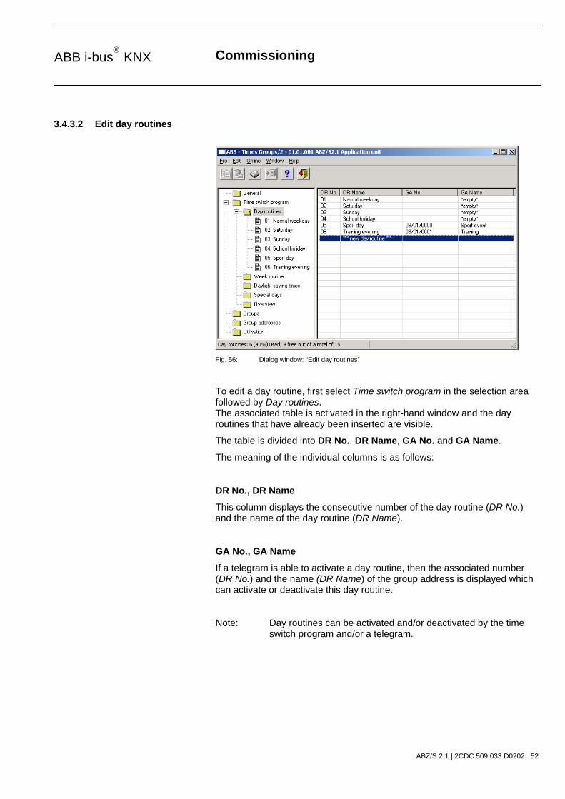
3.4.3.2 Edit day routines
Fig. 56: Dialog window: “Edit day routines”
To edit a day routine, first select Time switch program in the selection area followed by Day routines. The associated table is activated in the right-hand window and the day routines that have already been inserted are visible.
The table is divided into DR No., DR Name, GA No. and GA Name.
The meaning of the individual columns is as follows:
DR No., DR Name
This column displays the consecutive number of the day routine (DR No.) and the name of the day routine (DR Name).
GA No., GA Name
If a telegram is able to activate a day routine, then the associated number (DR No.) and the name (DR Name) of the group address is displayed which can activate or deactivate this day routine.
Note: Day routines can be activated and/or deactivated by the time switch program and/or a telegram.

Commissioning
ABZ/S 2.1 | 2CDC 509 033 D0202 53
ABB i-bus KNX
The parameter window for the selected day routine is activated in the following way:
- by double-clicking on the selected day routine or - by pressing the right mouse button and selecting Edit in the pop-up menu.
Fig. 57: Parameter window: “Select day routine”
The selected Day routine dialog window is now available for editing.
No.
The day routine number (DR No.) cannot be modified. It is automatically assigned by the application program and is a consecutive number for the unique identification of the day routine.
Name
The day routine name (DR Name) can be modified. There are a maximum of 50 characters available.
Options
The option can be deactivated. The assignment to the created group address is thereby deleted.
Commissioning
ABZ/S 2.1 | 2CDC 509 033 D0202 54
ABB i-bus KNX
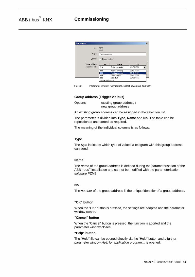
Fig. 58: Parameter window: “Day routine, Select new group address”
Group address (Trigger via bus)
Options: existing group address / new group address
An existing group address can be assigned in the selection list.
The parameter is divided into Type, Name and No. The table can be repositioned and sorted as required.
The meaning of the individual columns is as follows:
Type
The type indicates which type of values a telegram with this group address can send.
Name
The name of the group address is defined during the parameterisation of the ABB i-bus® installation and cannot be modified with the parameterisation software PZM2.
No.
The number of the group address is the unique identifier of a group address.
“OK” button
When the “OK” button is pressed, the settings are adopted and the parameter window closes.
“Cancel” button
When the “Cancel” button is pressed, the function is aborted and the parameter window closes.
“Help” button
The “Help” file can be opened directly via the “Help” button and a further parameter window Help for application program… is opened.

Commissioning
ABZ/S 2.1 | 2CDC 509 033 D0202 55
ABB i-bus KNX
After selecting the option new group address, the associated dialog window Add group addresses is activated.
Fig. 59: Dialog window: “Day routine, Select group address”
New group addresses can be created by dragging & dropping main groups, middle groups and subgroups.
The Accept button is activated by clicking on the new group address in the right-hand window.
The new group address is adopted in the following way:
- by double-clicking on the active group address or - by pressing the right mouse button and selecting Accept in the pop-up menu or - by pressing the Accept button.
The dialog window is closed by pressing the Accept button.
Note: The transfer of the newly created group address to ETS3 is only carried out after exiting the ABZ/S parameterisation and after confirming the prompt that the modified data should be saved. The editing of the group addresses such as modification of the description or deletion can only be carried out in ETS3.

Commissioning
ABZ/S 2.1 | 2CDC 509 033 D0202 56
ABB i-bus KNX
3.4.3.3 Delete day routines
Fig. 60: Dialog window: “Delete day routines”
To delete a day routine, first select Time switch program in the selection area followed by Day routines. The associated table is activated in the right-hand window and the day routines that have already been inserted are visible.
The table is divided into DR No., DR Name, GA No. and GA Name.
The meaning of the individual columns is as follows:
DR No., DR Name
This column displays the consecutive number of the day routine (DR No.) and the name of the day routine (DR Name).
GA No., GA Name
If a telegram is able to activate a day routine, then the associated number (DR No.) and the name (DR Name) of the group address is displayed which can activate or deactivate this day routine.
Note: Day routines can be activated and/or deactivated by the time switch program and/or a telegram.

Commissioning
ABZ/S 2.1 | 2CDC 509 033 D0202 57
ABB i-bus KNX
Select the day routine which should be deleted e.g. Training evening.
Fig. 61: Dialog window: “Select day routine”
The selected day routine is deleted in the following way:
- by pressing the Del button or - by pressing the right mouse button and selecting Delete in the pop-up menu.
“Yes” button
Before the day routine can be deleted, a prompt must be confirmed with Yes.
Fig. 62: Parameter window: “Day routine, Prompt”
“No” button
If the No button is selected, the day routine is not deleted.
“Cancel” button
When the “Cancel” button is pressed, the function is aborted and the parameter window closes.

Commissioning
ABZ/S 2.1 | 2CDC 509 033 D0202 58
ABB i-bus KNX
3.4.4 Switching time - General
Fig. 63: Dialog window: “Switching time – General”
The interval at which the time switch program of the Application Unit Time sends a telegram with a defined group address and a defined value on the bus, is designated as a switching time.

Commissioning
ABZ/S 2.1 | 2CDC 509 033 D0202 59
ABB i-bus KNX
3.4.4.1 Insert new switching time
Note: Before a switching time is inserted, a day routine must have been created under Day routines.
Fig. 64: Dialog window: “Insert switching time”
To insert a switching time, first select Time switch program, Day routines in the selection area followed by a day routine, e.g. 01: Normal weekday.
The associated table is activated in the right-hand window.
The table is divided into Time, GA No., GA Name, Value, Type and SoC.
The meaning of the individual columns is as follows:
Time
This column displays the set switching time at which a telegram is sent.
GA No.
The number of the group address is the unique identifier of a group address.
GA Name
The name of the group address is displayed here.
Value
This column displays which value is sent with the group address.

Commissioning
ABZ/S 2.1 | 2CDC 509 033 D0202 60
ABB i-bus KNX
Type
The type indicates which type of values a telegram with this group address can send.
SoC (Send on Change)
A tick in the SoC column indicates that a telegram is only sent if the value differs from the last value that was sent e.g. if the light should be switched on and is already switched on, this telegram is not sent.
Note: Day routines can be activated and/or deactivated by the time switch program and/or by a telegram.

Commissioning
ABZ/S 2.1 | 2CDC 509 033 D0202 61
ABB i-bus KNX
The parameter window Switching time for day routine, Normal weekday is activated in the following way:
- by double-clicking on *** new switching time *** or - by pressing the right mouse button and selecting New switching time in the pop-up menu or - by selecting Edit in the menu bar and then activating New switching time in the pop-up menu.
Fig. 65: Parameter window: “Insert new switching time”
Time
This parameter defines the time at which a telegram is sent, thereby activating a function.
The displays for hours and minutes can be edited separately via the Left arrow and Right arrow buttons.

Commissioning
ABZ/S 2.1 | 2CDC 509 033 D0202 62
ABB i-bus KNX
Fig. 66: Parameter window: “Switching time, Select new group address”
Group address
Option: new group address
The parameter is divided into Type, Name and No. The table can be arranged and sorted as required.
The meaning of the individual columns is as follows:
Type
The type indicates which type of values a telegram with this group address can send.
Name
The name of the group address is defined when configuring the ABB i-bus® installation and cannot be modified with the parameterisation software PZM2.
No.
The number of the group address is the unique identifier of a group address.

Commissioning
ABZ/S 2.1 | 2CDC 509 033 D0202 63
ABB i-bus KNX
After selecting the option new group address, the associated dialog window Add group addresses is activated.
Fig. 67: Dialog window: “Switching time, Add group addresses”
The main group, middle group and the subgroup are created in sequence via drag & drop.
Fig. 68: Parameter window: “Switching time, Create new main group, middle group and subgroup”
Note: The function descriptions and screenshots of the application program in this product manual all relate to ETS3. The application program for ETS4 has now become available.
The only difference between both program versions is the number of possible main groups: ETS3 = up to 15 main groups ETS4 = up to 31 main groups

Commissioning
ABZ/S 2.1 | 2CDC 509 033 D0202 64
ABB i-bus KNX
Fig. 69: Parameter window: “Switching time, Main group, middle group and subgroup created”
By marking New middle group in the left-hand window, the newly created group address is visible in the right-hand window.
Fig. 70: Dialog window: “Switching time, Middle group marked”
The Accept button is activated by clicking on the group address in the right-hand window.
Fig. 71: Dialog window: “Switching time, Subgroup marked”
The new group address is adopted in the following way:
- by double-clicking on the active group address or - by pressing the right mouse button and selecting Accept in the pop-up menu or - by pressing the Accept button.

Commissioning
ABZ/S 2.1 | 2CDC 509 033 D0202 65
ABB i-bus KNX
After pressing the Accept button, a further dialog window Group address becomes active. The data type for the newly created group address is selected in this window.
Fig. 72: Parameter window: “Switching time, Select data type”
“OK” button
When the “OK” button is pressed, the settings are adopted and the parameter window closes.
“Cancel” button
When the “Cancel” button is pressed, the function is aborted and the parameter window closes.
“Help” button
The “Help” file can be opened directly via the “Help” button and a further parameter window Help for application program… is opened.
Note: The transfer of the newly created group address to ETS3 is only carried out after exiting the ABZ/S parameterisation and after confirming the prompt that the modified data should be saved. The editing of the group addresses such as modification of the description or deletion can only be carried out in ETS3.

Commissioning
ABZ/S 2.1 | 2CDC 509 033 D0202 66
ABB i-bus KNX
Note: Different options appear in the Object value parameter depending on the type which has been selected for the group address.
Type 1 bit
Fig. 73: Parameter window: “Switching time, Data type 1 bit”
Object value (0…1)
Options: 0/1
This parameter is used to select which object value is sent.

Commissioning
ABZ/S 2.1 | 2CDC 509 033 D0202 67
ABB i-bus KNX
Type 2 bit priority
Fig. 74: Parameter window: “Switching time, Data type 2 bit priority”
Object value
Options: Free/ Forced ON/ Forced OFF
This parameter is used to select which object value is sent. The priority control function is explained in the following table:
Bit 1 Bit 0 Access Description
0 0 Free
0 1 Free
The priority object has enabled e.g. the switch actuator. The output switches depending on the value of the switch object.
1 0 OFF The priority object has switched e.g. the switch actuator OFF with priority control. The switch object has no function.
1 1 ON The priority object has switched e.g. the switch actuator ON with priority control. The switch object has no function.
Table 4: Priority object
Note: 4 different values can be sent with the telegram. So-called priority objects can thus be addressed in the EIB devices. If a channel e.g. in a switch actuator should switch on or off, the value 1 or 0 is sent to the assigned switch object. If a priority object is also assigned to this channel, the value that was sent to the priority object defines the behaviour of the channel.

Commissioning
ABZ/S 2.1 | 2CDC 509 033 D0202 68
ABB i-bus KNX
Type 1 byte unsigned (0…255)
Fig. 75: Parameter window: “Switching time, Data type 1 byte unsigned (0…255)”
Object value (0…255) and Standard
Options: 0…255
This parameter is used to select which object value is sent.
If Standard is also selected, the object value is issued without a unit of measurement.
Type 1 byte unsigned (0…100%)
Fig. 76: Parameter window: “Switching time, Data type 1 byte unsigned (0…100%)”
Object value (0…100%) and in %
Options: 0.00…100%
This parameter is used to select which object value is sent.
If the option in % is also selected, 0 = 0% and 255 = 100% are assigned to the object values.

Commissioning
ABZ/S 2.1 | 2CDC 509 033 D0202 69
ABB i-bus KNX
Type 1 byte signed (-128…127)
Fig. 77: Parameter window: “Switching time, Data type 1 byte signed (-128…127)”
Object value (-128…127)
Options: -128…0…127
This parameter is used to select which object value is sent.
Type 2 byte unsigned (0…65,535)
Fig. 78: Parameter window: “Switching time, Data type 2 byte unsigned (0…65,535)”
Object value (0…65,535)
Options: 0…65,535
This parameter is used to select which object value is sent.

Commissioning
ABZ/S 2.1 | 2CDC 509 033 D0202 70
ABB i-bus KNX
Type 2 byte signed (-32,768…32,767)
Fig. 79: Parameter window: “Switching time, Data type 2 byte signed (-32,768…32,767)”
Object value (-32,768…32,767)
Options: -32,768…0…32,767
This parameter is used to select which object value is sent.
Type 2 byte floating point
Fig. 80: Parameter window: “Switching time, Data type 2 byte floating point”
Object value (-163.84…163.76) and Exponent 3 (Temp.)
Options: -163.84…0…163.76
This parameter is used to select which object value is sent.

Commissioning
ABZ/S 2.1 | 2CDC 509 033 D0202 71
ABB i-bus KNX
Exponent
Options: Auto / 0…3 (Temp.)…15
This parameter is used to select which exponent is assigned to the object value.
Note: Different object values can be set, depending on the exponent which is selected. The table below shows all the options.
Exponent Object value
Auto -671,088.64…0.00…670,760.96
0 -20.48…0.00…20.47
1 -40.96…0.00…40.94
2 -81.92…0.00…81.88
3 (Temp.) -163.84…0.00…163.76
4 -327.68…0.00…327.52
5 -655.36…0.00…655.04
6 -1,310.72…0.00…1,310.08
7 -2,621.44…0.00…2,620.16
8 -5,242.88…0.00…5,240.32
9 -10,485.76…0.00…10,480.64
10 -20,971.52…0.00…20,961.28
11 -41,943.04…0.00…41,922.56
12 -88,386.08…0.00…83,845.12
13 -167,772.16…0.00…167,690.24
14 -335,544.32…0.00…335,380.48
15 -671,088.64…0.00…670,760.96 Table 5: Exponent

Commissioning
ABZ/S 2.1 | 2CDC 509 033 D0202 72
ABB i-bus KNX
Options
With the option Send on change only, it is defined that a telegram is only sent if the value differs from the value that was last sent e.g. if the light should be switched on and is already switched on, this telegram is not sent.
If the option Send on change only is not selected, the group address and the object value are sent at the set time.
“OK” button
A new switching time is inserted via the OK button.
“Close” button
The parameter window is closed via the Close button.
“Help” button
The “Help” file can be opened directly via the “Help” button and a further parameter window Help for application program… is opened.

Commissioning
ABZ/S 2.1 | 2CDC 509 033 D0202 73
ABB i-bus KNX
3.4.4.2 Edit switching time
Fig. 81: Dialog window: “Edit switching time”
To edit a switching time, first select Time switch program, Day routines in the selection area followed by a specific day routine e.g. 7:55. The associated table is activated in the right-hand window and the already inserted switching times are visible.
The table is divided into Time, GA No., GA Name, Value, Type and SoC.
The meaning of the individual columns is as follows:
Time
This column displays the set switching time at which a telegram is sent.
GA No.
The number of the group address is the unique identifier of a group address.
GA Name
The name of the group address is displayed here.
Value
This column displays which value is sent with the group address.

Commissioning
ABZ/S 2.1 | 2CDC 509 033 D0202 74
ABB i-bus KNX
Type
The type indicates which type of values a telegram with this group address can send.
SoC (Send on Change)
A tick in the SoC column indicates that a telegram is only sent if the value differs from the last value that was sent e.g. if the light should be switched on and is already switched on, this telegram is not sent.

Commissioning
ABZ/S 2.1 | 2CDC 509 033 D0202 75
ABB i-bus KNX
The parameter window Switching time for day routine – Normal weekday is activated in the following way:
- by double-clicking on the selected switching time or - by pressing the right mouse button and selecting Edit in the pop-up menu.
Fig. 82: Parameter window: “Select switching time”
Time
The time can be edited e.g. via the Left arrow and Right arrow buttons.

Commissioning
ABZ/S 2.1 | 2CDC 509 033 D0202 76
ABB i-bus KNX
Fig. 83: Parameter window: “Switching time for day routine - Normal weekday, Select group address”
Group address
Options: existing group addresses / new group address
An existing group address can be assigned in the selection list.
The parameter is divided into Type, Name and No. The table can be arranged and sorted as required.
The meaning of the individual columns is as follows:
Type
The type indicates which type of values a telegram with this group address can send.
Name
The name of the group address is defined when configuring the ABB i-bus® installation and cannot be modified with the parameterisation software PZM2.
No.
The number of the group address is the unique identifier of a group address.

Commissioning
ABZ/S 2.1 | 2CDC 509 033 D0202 77
ABB i-bus KNX
After selecting the option new group address, the associated dialog window Add group addresses is activated.
Fig. 84: Dialog window: “Switching time, Select group address”
New group addresses can be created by dragging & dropping main groups, middle groups and subgroups.
The Accept button is activated by clicking on the new group address in the right-hand window.
The new group address is adopted in the following way:
- by double-clicking on the active group address or - by pressing the right mouse button and selecting Accept in the pop-up menu or - by pressing the Accept button.
Commissioning
ABZ/S 2.1 | 2CDC 509 033 D0202 78
ABB i-bus KNX
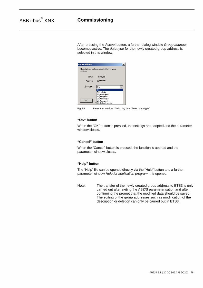
After pressing the Accept button, a further dialog window Group address becomes active. The data type for the newly created group address is selected in this window.
Fig. 85: Parameter window: “Switching time, Select data type”
“OK” button
When the “OK” button is pressed, the settings are adopted and the parameter window closes.
“Cancel” button
When the “Cancel” button is pressed, the function is aborted and the parameter window closes.
“Help” button
The “Help” file can be opened directly via the “Help” button and a further parameter window Help for application program… is opened.
Note: The transfer of the newly created group address to ETS3 is only carried out after exiting the ABZ/S parameterisation and after confirming the prompt that the modified data should be saved. The editing of the group addresses such as modification of the description or deletion can only be carried out in ETS3.
Commissioning
ABZ/S 2.1 | 2CDC 509 033 D0202 79
ABB i-bus KNX
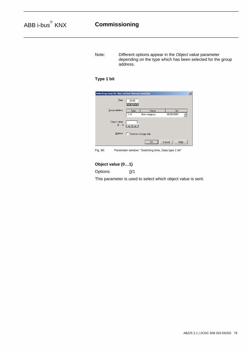
Note: Different options appear in the Object value parameter depending on the type which has been selected for the group address.
Type 1 bit
Fig. 86: Parameter window: “Switching time, Data type 1 bit”
Object value (0…1)
Options: 0/1
This parameter is used to select which object value is sent.

Commissioning
ABZ/S 2.1 | 2CDC 509 033 D0202 80
ABB i-bus KNX
Type 2 bit priority
Fig. 87: Parameter window: “Switching time, Data type 2 bit priority”
Object value
Options: Free/ Forced ON/ Forced OFF
This parameter is used to select which object value is sent. The priority control function is explained in the following table:
Bit 1 Bit 0 Access Description
0 0 Free
0 1 Free
The priority object has enabled e.g. the switch actuator. The output switches depending on the value of the switch object.
1 0 OFF The priority object has switched e.g. the switch actuator OFF with priority control. The switch object has no function.
1 1 ON The priority object has switched e.g. the switch actuator ON with priority control. The switch object has no function.
Table 6: Priority object
Note: 4 different values can be sent with the telegram. So-called priority objects can thus be addressed in the EIB devices. If a channel e.g. in a switch actuator should switch on or off, the value 1 or 0 is sent to the assigned switch object. If a priority object is also assigned to this channel, the value that was sent to the priority object defines the behaviour of the channel.
Commissioning
ABZ/S 2.1 | 2CDC 509 033 D0202 81
ABB i-bus KNX
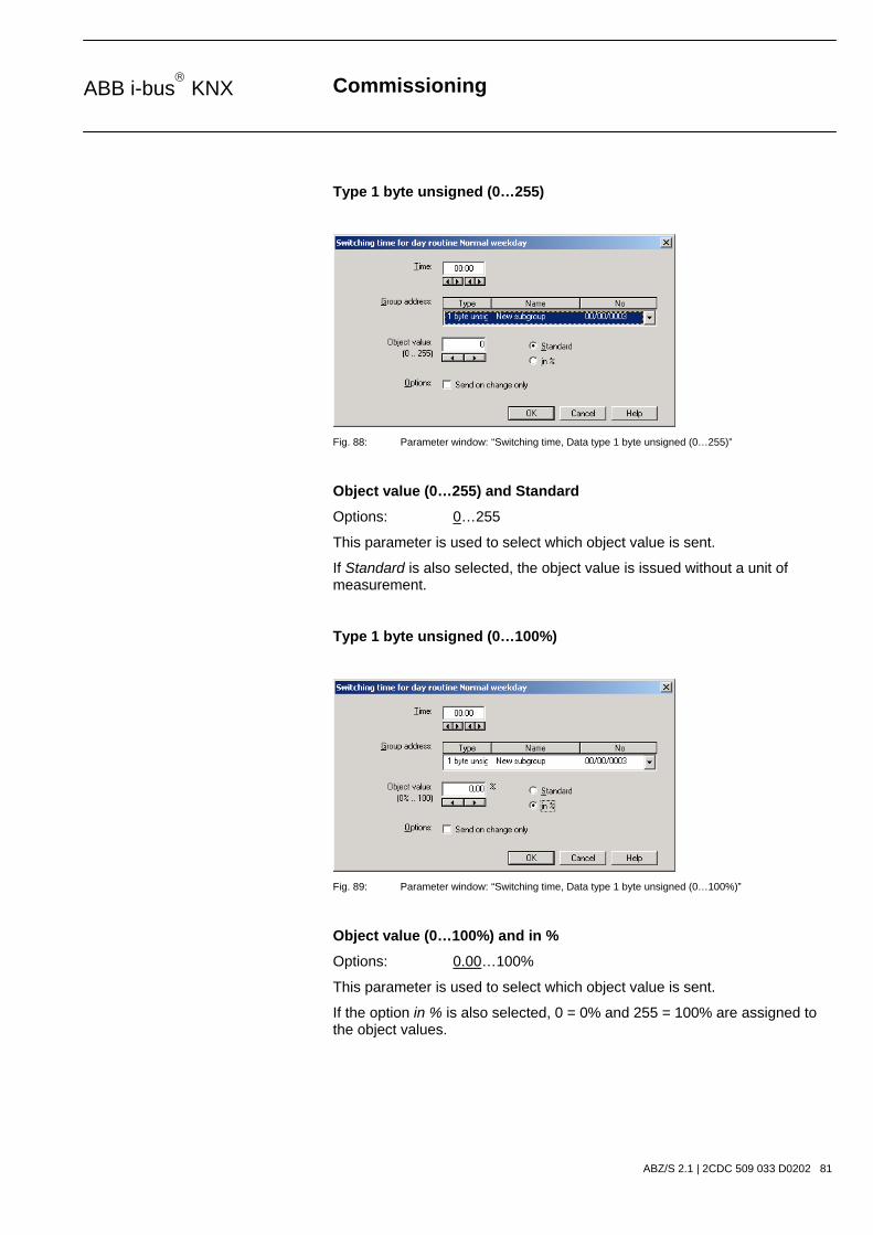
Type 1 byte unsigned (0…255)
Fig. 88: Parameter window: “Switching time, Data type 1 byte unsigned (0…255)”
Object value (0…255) and Standard
Options: 0…255
This parameter is used to select which object value is sent.
If Standard is also selected, the object value is issued without a unit of measurement.
Type 1 byte unsigned (0…100%)
Fig. 89: Parameter window: “Switching time, Data type 1 byte unsigned (0…100%)”
Object value (0…100%) and in %
Options: 0.00…100%
This parameter is used to select which object value is sent.
If the option in % is also selected, 0 = 0% and 255 = 100% are assigned to the object values.
Commissioning
ABZ/S 2.1 | 2CDC 509 033 D0202 82
ABB i-bus KNX
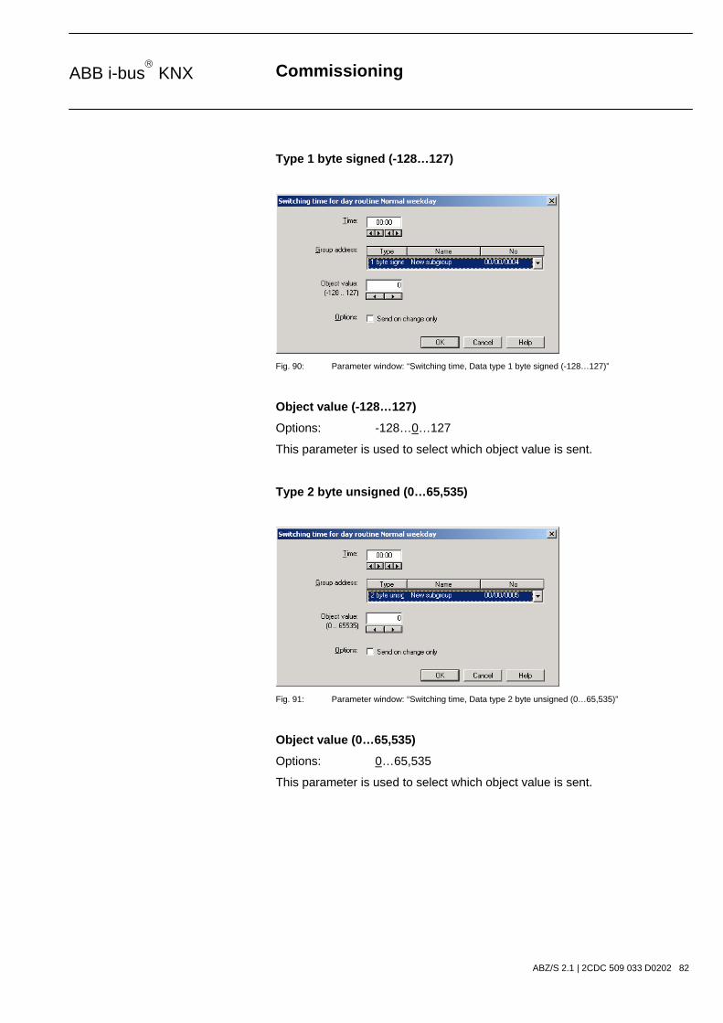
Type 1 byte signed (-128…127)
Fig. 90: Parameter window: “Switching time, Data type 1 byte signed (-128…127)”
Object value (-128…127)
Options: -128…0…127
This parameter is used to select which object value is sent.
Type 2 byte unsigned (0…65,535)
Fig. 91: Parameter window: “Switching time, Data type 2 byte unsigned (0…65,535)”
Object value (0…65,535)
Options: 0…65,535
This parameter is used to select which object value is sent.

Commissioning
ABZ/S 2.1 | 2CDC 509 033 D0202 83
ABB i-bus KNX
Type 2 byte signed (-32,768…32,767)
Fig. 92: Parameter window: “Switching time, Data type 2 byte signed (-32,768…32,767)”
Object value (-32,768…32,767)
Options: -32,768…0…32,767
This parameter is used to select which object value is sent.
Type 2 byte floating point
Fig. 93: Parameter window: “Switching time, Data type 2 byte floating point”
Object value (-163.84…163.76) and Exponent 3 (Temp.)
Options: -163.84…0…163.76
This parameter is used to select which object value is sent.

Commissioning
ABZ/S 2.1 | 2CDC 509 033 D0202 84
ABB i-bus KNX
Exponent
Options: Auto / 0…3 (Temp.)…15
This parameter is used to select which exponent is assigned to the object value.
Note: Different object values can be set, depending on the exponent which is selected. The table below shows all the options.
Exponent Object value
Auto -671,088.64…0.00…670,760.96
0 -20.48…0.00…20.47
1 -40.96…0.00…40.94
2 -81.92…0.00…81.88
3 (Temp.) -163.84…0.00…163.76
4 -327.68…0.00…327.52
5 -655.36…0.00…655.04
6 -1,310.72…0.00…1,310.08
7 -2,621.44…0.00…2,620.16
8 -5,242.88…0.00…5,240.32
9 -10,485.76…0.00…10,480.64
10 -20,971.52…0.00…20,961.28
11 -41,943.04…0.00…41,922.56
12 -88,386.08…0.00…83,845.12
13 -167,772.16…0.00…167,690.24
14 -335,544.32…0.00…335,380.48
15 -671,088.64…0.00…670,760.96 Table 7: Exponent

Commissioning
ABZ/S 2.1 | 2CDC 509 033 D0202 85
ABB i-bus KNX
Options
With the option Send on change only, it is defined that a telegram is only sent if the value differs from the value that was last sent e.g. if the light should be switched on and is already switched on, this telegram is not sent.
If the option Send on change only is not selected, the group address and the object value are sent at the set time.
“OK” button
When the “OK” button is pressed, the settings are adopted and the parameter window closes.
“Cancel” button
When the “Cancel” button is pressed, the function is aborted and the parameter window closes.
“Help” button
The “Help” file can be opened directly via the “Help” button and a further parameter window Help for application program… is opened.
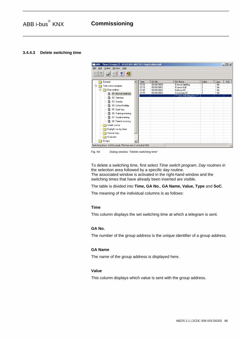
Commissioning
ABZ/S 2.1 | 2CDC 509 033 D0202 86
ABB i-bus KNX
3.4.4.3 Delete switching time
Fig. 94: Dialog window: “Delete switching time”
To delete a switching time, first select Time switch program, Day routines in the selection area followed by a specific day routine. The associated window is activated in the right-hand window and the switching times that have already been inserted are visible.
The table is divided into Time, GA No., GA Name, Value, Type and SoC.
The meaning of the individual columns is as follows:
Time
This column displays the set switching time at which a telegram is sent.
GA No.
The number of the group address is the unique identifier of a group address.
GA Name
The name of the group address is displayed here.
Value
This column displays which value is sent with the group address.

Commissioning
ABZ/S 2.1 | 2CDC 509 033 D0202 87
ABB i-bus KNX
Type
The type indicates which type of values a telegram with this group address can send.
SoC (Send on Change)
A tick in the SoC column indicates that a telegram is only sent if the value differs from the last value that was sent e.g. if the light should be switched on and is already switched on, this telegram is not sent.
Note: Day routines can be activated and/or deactivated by the time switch program and/or by a telegram.
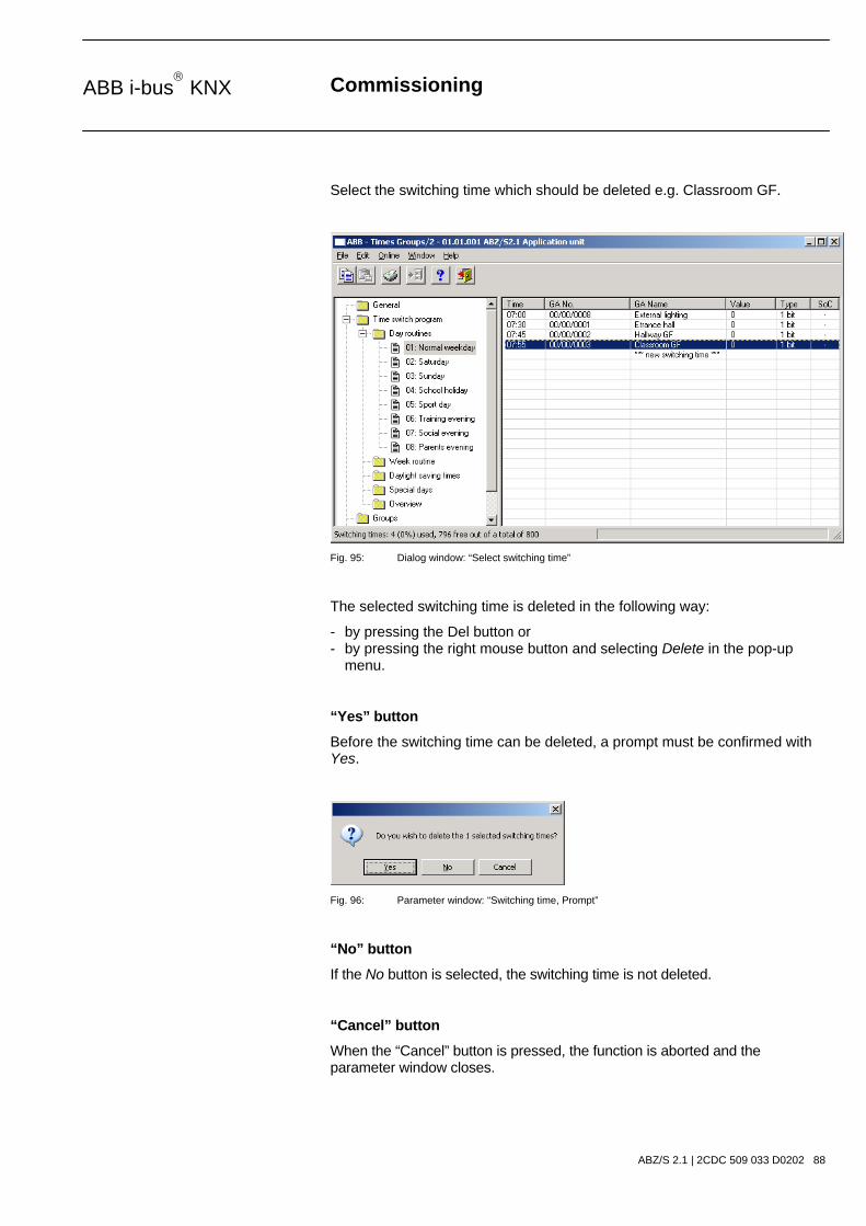
Commissioning
ABZ/S 2.1 | 2CDC 509 033 D0202 88
ABB i-bus KNX
Select the switching time which should be deleted e.g. Classroom GF.
Fig. 95: Dialog window: “Select switching time”
The selected switching time is deleted in the following way:
- by pressing the Del button or - by pressing the right mouse button and selecting Delete in the pop-up menu.
“Yes” button
Before the switching time can be deleted, a prompt must be confirmed with Yes.
Fig. 96: Parameter window: “Switching time, Prompt”
“No” button
If the No button is selected, the switching time is not deleted.
“Cancel” button
When the “Cancel” button is pressed, the function is aborted and the parameter window closes.

Commissioning
ABZ/S 2.1 | 2CDC 509 033 D0202 89
ABB i-bus KNX
3.4.4.4 Copy/insert switching time
Fig. 97: Parameter window: “Copy/insert switching time”
To copy or insert a switching time, first select Time switch program, Day routines in the selection area followed by a specific day routine. The associated window is activated in the right-hand window and the switching times that have already been inserted are visible.
The table is divided into Time, GA No., GA Name, Value, Type and SoC.
The meaning of the individual columns is as follows:
Time
This column displays the set switching time at which a telegram is sent.
GA No.
The number of the group address is the unique identifier of a group address.
GA Name
The name of the group address is displayed here.
Value
This column displays which value is sent with the group address.

Commissioning
ABZ/S 2.1 | 2CDC 509 033 D0202 90
ABB i-bus KNX
Type
The type indicates which type of values a telegram with this group address can send.
SoC (Send on Change)
A tick in the SoC column indicates that a telegram is only sent if the value differs from the last value that was sent e.g. if the light should be switched on and is already switched on, this telegram is not sent.
Note: Day routines can be activated and/or deactivated by the time switch program and/or by a telegram.
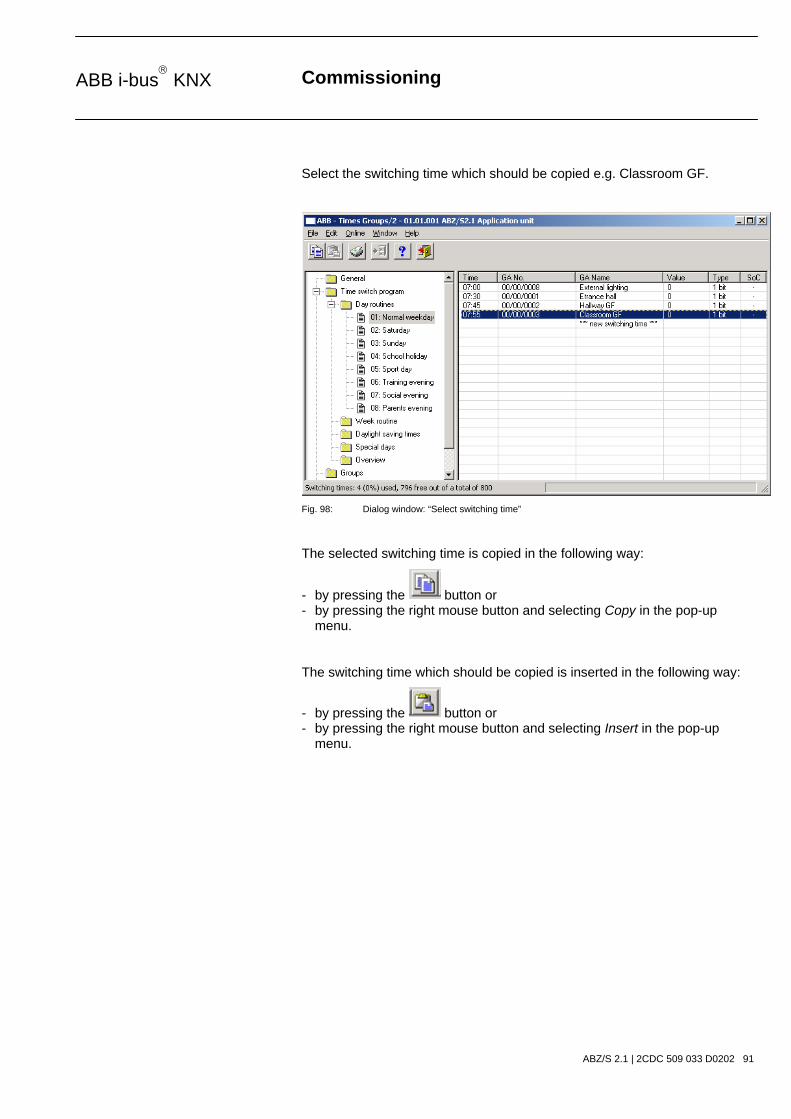
Commissioning
ABZ/S 2.1 | 2CDC 509 033 D0202 91
ABB i-bus KNX
Select the switching time which should be copied e.g. Classroom GF.
Fig. 98: Dialog window: “Select switching time”
The selected switching time is copied in the following way:
- by pressing the button or - by pressing the right mouse button and selecting Copy in the pop-up menu.
The switching time which should be copied is inserted in the following way:
- by pressing the button or - by pressing the right mouse button and selecting Insert in the pop-up menu.

Commissioning
ABZ/S 2.1 | 2CDC 509 033 D0202 92
ABB i-bus KNX
Before the switching time can be inserted, a new switching time must be entered.
Fig. 99: Parameter window: “Set switching time”
“Accept” button
When this button is pressed, the settings are adopted and the parameter window closes.
“Cancel” button
When the “Cancel” button is pressed, the function is aborted and the parameter window closes.
“Help” button
The “Help” file can be opened directly via the “Help” button and a further parameter window Help for application program… is opened.

Commissioning
ABZ/S 2.1 | 2CDC 509 033 D0202 93
ABB i-bus KNX
3.4.5 Week routine - General
Fig. 100: Dialog window: “Week routine - General”
The week routine is compiled from the day routines. A day routine can be assigned to each day of the week (Monday to Sunday).

Commissioning
ABZ/S 2.1 | 2CDC 509 033 D0202 94
ABB i-bus KNX
3.4.5.1 Insert new week routine
Note: Before a week routine is inserted, a day routine and a switching time must have been created under Day routines.
Fig. 101: Dialog window: “Insert week routine”
To insert a week routine, first select Time switch program in the selection area followed by Week routine. The associated table is activated in the right-hand window.
The table is divided into Weekday, DR No. and DR Name.
The meaning of the individual columns is as follows:
Weekday
All the days of the week are automatically displayed in this column.
DR No., DR Name
This column displays the consecutive numbers of the day routines (DR No.) and the names of the day routines (DR Name).
Note: If no day routines have yet been assigned to a weekday, there is no day routine number (DR No.) and “none” is entered as the name of the day routine (DR Name).

Commissioning
ABZ/S 2.1 | 2CDC 509 033 D0202 95
ABB i-bus KNX
The parameter window Standard day routine for Monday is activated in the following way:
- by double-clicking on the selected weekday or - by pressing the right mouse button and selecting Edit in the pop-up menu.
Fig. 102: Parameter window: “Standard day routine for Monday, Insert day routine”
Day routine
Options: none / existing day routines
An existing day routine can be assigned in the selection list.
The parameter is divided into Name and No. The table can be arranged and sorted as required.
The meaning of the individual columns is as follows:
Name
This column displays the name of the day routine (DR Name).
No.
This column displays the consecutive number of the day routine (DR No.).
“OK” button
When the “OK” button is pressed, the settings are adopted and the parameter window closes.
“Cancel” button
When the “Cancel” button is pressed, the function is aborted and the parameter window closes.
“Help” button
The “Help” file can be opened directly via the “Help” button and a further parameter window Help for application program… is opened.

Commissioning
ABZ/S 2.1 | 2CDC 509 033 D0202 96
ABB i-bus KNX
3.4.5.2 Edit week routine
Fig. 103: Dialog window: “Edit week routine”
To edit a week routine, first select Time switch program in the selection area followed by Week routine e.g. Sunday. The associated table is activated in the right-hand window.
The table is divided into Weekday, DR No. and DR Name.
The meaning of the individual columns is as follows:
Weekday
The weekdays that have been created are displayed in this column.
DR No., DR Name
This column displays the consecutive numbers of the day routines (DR No.) and the names of the day routines (DR Name).
Note: If no day routines have yet been assigned to a day of the week, no day routine number (DR No.) is displayed and “none” is entered as the name of the day routine (DR Name).
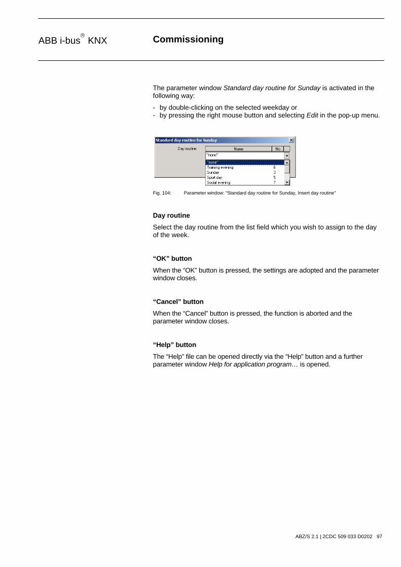
Commissioning
ABZ/S 2.1 | 2CDC 509 033 D0202 97
ABB i-bus KNX
The parameter window Standard day routine for Sunday is activated in the following way:
- by double-clicking on the selected weekday or - by pressing the right mouse button and selecting Edit in the pop-up menu.
Fig. 104: Parameter window: “Standard day routine for Sunday, Insert day routine”
Day routine
Select the day routine from the list field which you wish to assign to the day of the week.
“OK” button
When the “OK” button is pressed, the settings are adopted and the parameter window closes.
“Cancel” button
When the “Cancel” button is pressed, the function is aborted and the parameter window closes.
“Help” button
The “Help” file can be opened directly via the “Help” button and a further parameter window Help for application program… is opened.

Commissioning
ABZ/S 2.1 | 2CDC 509 033 D0202 98
ABB i-bus KNX
3.4.5.3 Delete week routine
Fig. 105: Dialog window: “Delete week routine”
To delete a week routine, first select Time switch program in the selection area followed by Week routine. The associated table is activated in the right-hand window.
The table is divided into Weekday, DR No. and DR Name.
The meaning of the individual columns is as follows:
Weekday
This column displays the weekdays that have been created.
DR No., DR Name
This column displays the consecutive numbers of the day routines (DR No.) and the names of the day routines (DR Name).
Note: If no day routines have yet been assigned to a day of the week, no day routine number (DR No.) is displayed and “none” is entered as the name of the day routine (DR Name).

Commissioning
ABZ/S 2.1 | 2CDC 509 033 D0202 99
ABB i-bus KNX
Select the weekday for the day routine that is to be deleted e.g. Monday.
Fig. 106: Dialog window: “Select week routine”
The selected day routine (DR Name) is deleted in the following way:
- by pressing the Del button or - by pressing the right mouse button and selecting Delete in the pop-up menu or - by selecting Edit in the menu bar and then activating Delete in the pop-up menu.
After carrying out the process described above, “none” is automatically entered under the column DR Name i.e. the day routine is deleted.

Commissioning
ABZ/S 2.1 | 2CDC 509 033 D0202 100
ABB i-bus KNX
3.4.6 Daylight saving times - General
Fig. 107: Dialog window: “Daylight saving times - General”
With this function, the changeover days, the changeover times and the offset for daylight saving can be calculated or defined.
Note: The basis for calculating the daylight saving times is the provision of your PC equipment.

Commissioning
ABZ/S 2.1 | 2CDC 509 033 D0202 101
ABB i-bus KNX
3.4.6.1 Insert new daylight saving time
Fig. 108: Dialog window: “Insert new daylight saving time”
To insert a daylight saving time, first select Time switch program in the selection area followed by Daylight saving times. The associated table is activated in the right-hand window.
The table is divided into Year, Start, End and Offset.
The meaning of the individual columns is as follows:
Year
The year is displayed in this column.
Start
The start of the daylight saving time is displayed in this column.
End
The end of the daylight saving time is displayed in this column.
Offset
The time adjustment (offset) is displayed in this column.

Commissioning
ABZ/S 2.1 | 2CDC 509 033 D0202 102
ABB i-bus KNX
The parameter window Daylight saving time is activated in the following way:
- by double-clicking on *** new daylight saving time *** or - by pressing the right mouse button and selecting New daylight saving time in the pop-up menu or - by selecting Edit in the menu bar and then activating New daylight saving time in the pop-up menu.
Fig. 109: Parameter window: “Insert daylight saving time”
Calculate
If the Calculate button is pressed, the daylight saving times can be calculated automatically and in sequence. The calculated daylight saving times appear under Start and End. The calculated daylight saving times can be adopted with the help of the Insert button.
The prerequisite for the automatic calculation is the activation of the Automatically calculate parameter.
Note: The start and end of the daylight saving time are calculated according to the conversion rules stored in your operating system for converting standard time to daylight saving time.
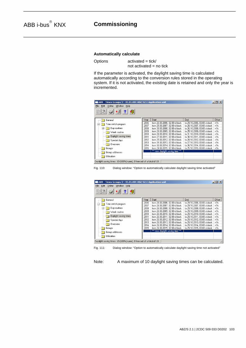
Commissioning
ABZ/S 2.1 | 2CDC 509 033 D0202 103
ABB i-bus KNX
Automatically calculate
Options activated = tick/ not activated = no tick
If the parameter is activated, the daylight saving time is calculated automatically according to the conversion rules stored in the operating system. If it is not activated, the existing date is retained and only the year is incremented.
Fig. 110: Dialog window: “Option to automatically calculate daylight saving time activated”
Fig. 111: Dialog window: “Option to automatically calculate daylight saving time not activated”
Note: A maximum of 10 daylight saving times can be calculated.

Commissioning
ABZ/S 2.1 | 2CDC 509 033 D0202 104
ABB i-bus KNX
Start, End
The daylight saving time is defined by entering the date (on) and time (at) of the start and end.
The date for the start and end can be set in a range between 1.1.2000 and 31.12.2035. The representation is in numbers which are separated by full stops in the sequence Day. Month. Year. Entries for the year in the range 36...99 are rejected. To the right of the input field for the date, there is a button with which the calendar for the current date can be displayed. The input of the date for the start and end can be carried out via the selection of a date in the calendar or through the direct input of the date.
The displays for the hour can be edited via the buttons Left arrow and Right arrow.
Offset
An offset, i.e. the time adjustment can be set.
Note: With the start of the daylight saving time, the current time of the internal clock is adjusted by this value and reset with the end of the daylight saving time.
“Insert” button
The settings are adopted via the “Insert” button.
“Close” button
When the “Close” button is pressed, the function is ended and the parameter window closes.
“Help” button
The “Help” file can be opened directly via the “Help” button and a further parameter window Help for application program… is opened.

Commissioning
ABZ/S 2.1 | 2CDC 509 033 D0202 105
ABB i-bus KNX
3.4.6.2 Edit daylight saving time
Fig. 112: Dialog window: “Edit daylight saving time”
To edit the daylight saving time, first select Time switch program in the selection area followed by Daylight saving times, e.g. the year 2006. The associated table is activated in the right-hand window.
The table is divided into Year, Start, End and Offset.
The meaning of the individual columns is as follows:
Year
The year is displayed in this column.
Start
The start of the daylight saving time is displayed in this column.
End
The end of the daylight saving time is displayed in this column.
Offset
The time adjustment (offset) is displayed in this column.
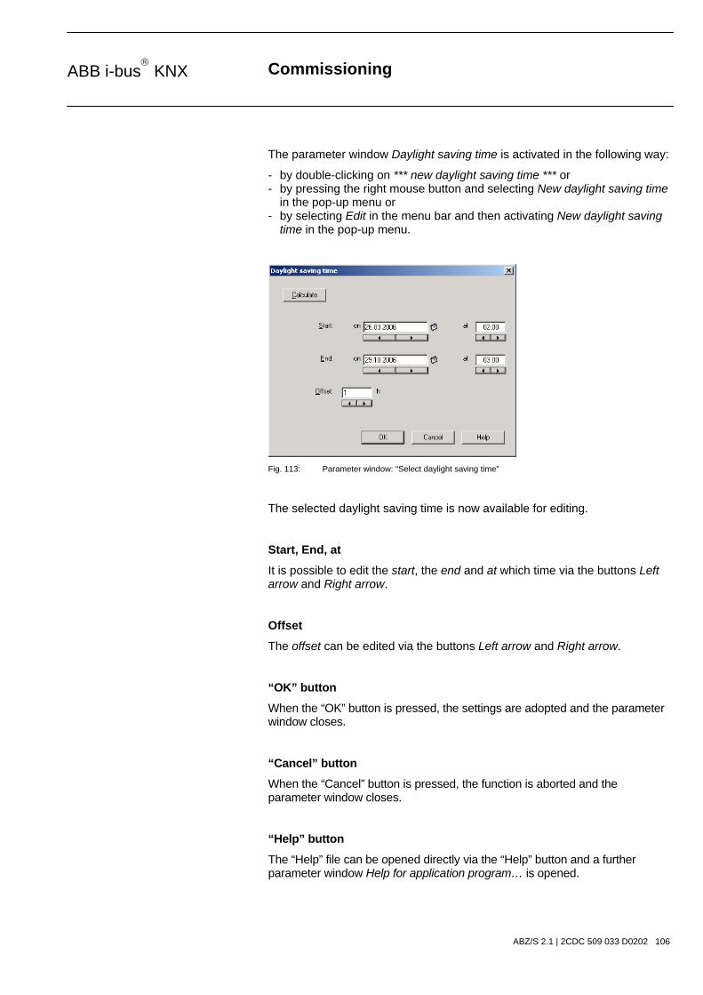
Commissioning
ABZ/S 2.1 | 2CDC 509 033 D0202 106
ABB i-bus KNX
The parameter window Daylight saving time is activated in the following way:
- by double-clicking on *** new daylight saving time *** or - by pressing the right mouse button and selecting New daylight saving time in the pop-up menu or - by selecting Edit in the menu bar and then activating New daylight saving time in the pop-up menu.
Fig. 113: Parameter window: “Select daylight saving time”
The selected daylight saving time is now available for editing.
Start, End, at
It is possible to edit the start, the end and at which time via the buttons Left arrow and Right arrow.
Offset
The offset can be edited via the buttons Left arrow and Right arrow.
“OK” button
When the “OK” button is pressed, the settings are adopted and the parameter window closes.
“Cancel” button
When the “Cancel” button is pressed, the function is aborted and the parameter window closes.
“Help” button
The “Help” file can be opened directly via the “Help” button and a further parameter window Help for application program… is opened.
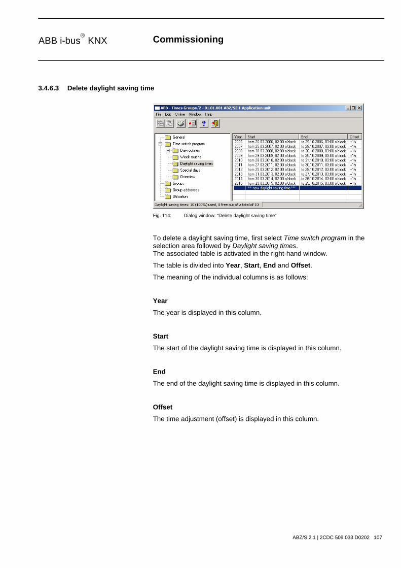
Commissioning
ABZ/S 2.1 | 2CDC 509 033 D0202 107
ABB i-bus KNX
3.4.6.3 Delete daylight saving time
Fig. 114: Dialog window: “Delete daylight saving time”
To delete a daylight saving time, first select Time switch program in the selection area followed by Daylight saving times. The associated table is activated in the right-hand window.
The table is divided into Year, Start, End and Offset.
The meaning of the individual columns is as follows:
Year
The year is displayed in this column.
Start
The start of the daylight saving time is displayed in this column.
End
The end of the daylight saving time is displayed in this column.
Offset
The time adjustment (offset) is displayed in this column.

Commissioning
ABZ/S 2.1 | 2CDC 509 033 D0202 108
ABB i-bus KNX
Select the daylight saving time which should be deleted e.g. the year 2006.
Fig. 115: Dialog window: “Select daylight saving time”
The selected daylight saving time is deleted in the following way:
- by pressing the Del button or - by pressing the right mouse button and selecting Delete in the pop-up menu or - by selecting Edit in the menu bar and then activating Delete in the pop-up menu.
“Yes” button
Before the daylight saving time can be deleted, a prompt must be confirmed with Yes.
Fig. 116: Parameter window: “Daylight saving time, Prompt”
“No” button
The daylight saving time is not deleted when the No button is pressed.
“Cancel” button
When the “Cancel” button is pressed, the function is aborted and the parameter window closes.
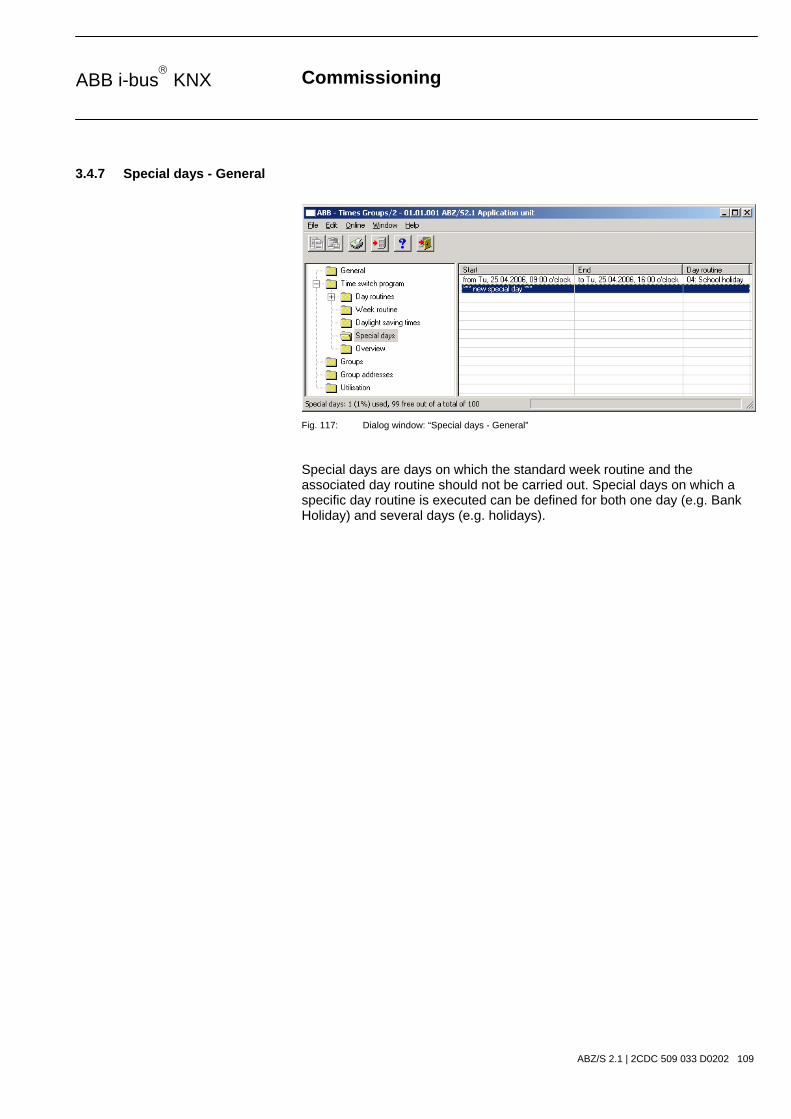
Commissioning
ABZ/S 2.1 | 2CDC 509 033 D0202 109
ABB i-bus KNX
3.4.7 Special days - General
Fig. 117: Dialog window: “Special days - General”
Special days are days on which the standard week routine and the associated day routine should not be carried out. Special days on which a specific day routine is executed can be defined for both one day (e.g. Bank Holiday) and several days (e.g. holidays).

Commissioning
ABZ/S 2.1 | 2CDC 509 033 D0202 110
ABB i-bus KNX
3.4.7.1 Insert new special day
Note: Before a new special day is inserted, a day routine must have been created under Day routines.
Fig. 118: Dialog window: “Insert new special day”
To insert a special day, first select Time switch program in the selection area followed by Special days. The associated table is activated in the right-hand window.
The table is divided into Start, End and Day routine.
The meaning of the individual columns is as follows:
Start
The start of the special day is displayed in this column.
End
The end of the special day is displayed in this column.
Day routine
This column displays the day routine.

Commissioning
ABZ/S 2.1 | 2CDC 509 033 D0202 111
ABB i-bus KNX
The parameter window Special day range is activated in the following way:
- by double-clicking on *** new special day *** or - by pressing the right mouse button and selecting New special day in the pop-up menu or - by selecting Edit in the menu bar and then activating New special day in the pop-up menu.
Fig. 119: Parameter window: “Set special day range”
Start, End
By entering the date (on), time (at), start and end of the period, it is defined which day routine should apply which deviates from the standard week routine.
The date for the start and end can be set in the range between 1.1.2000 and 31.12. 2035. The representation is in numbers which are separated by full stops in the sequence Day. Month. Year. Entries for the year in the range 36...99 are rejected. To the right of the input field for the date, there is a button with which the calendar for the current date can be displayed. The input of the date for the start and end can be carried out via the selection of a date in the calendar or through the direct input of the date.
The displays for the hours and minutes can be edited separately via the buttons Left arrow and Right arrow.

Commissioning
ABZ/S 2.1 | 2CDC 509 033 D0202 112
ABB i-bus KNX
Fig. 120: Parameter window: “Special day range, Select day routine”
Day routine
Select a day routine from the list of day routines.
Name
This column displays the names of the day routines (DR Name).
No.
This column displays the consecutive number of the day routine (DR No.).
“Insert” button
The settings are adopted via the “Insert” button.
“Close” button
When the “Close” button is pressed, the function is ended and the parameter window closes.
“Help” button
The “Help” file can be opened directly via the “Help” button and a further parameter window Help for application program… is opened.
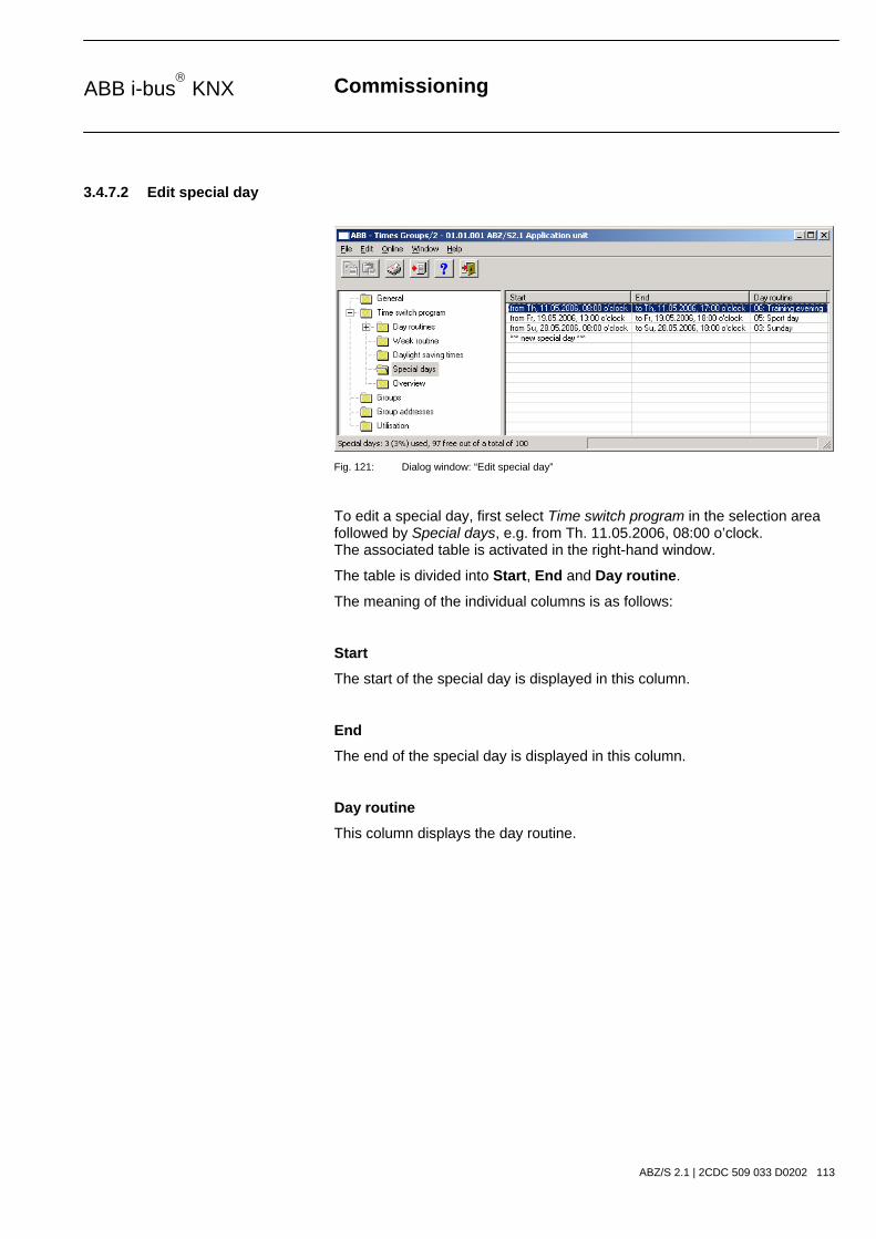
Commissioning
ABZ/S 2.1 | 2CDC 509 033 D0202 113
ABB i-bus KNX
3.4.7.2 Edit special day
Fig. 121: Dialog window: “Edit special day”
To edit a special day, first select Time switch program in the selection area followed by Special days, e.g. from Th. 11.05.2006, 08:00 o’clock. The associated table is activated in the right-hand window.
The table is divided into Start, End and Day routine.
The meaning of the individual columns is as follows:
Start
The start of the special day is displayed in this column.
End
The end of the special day is displayed in this column.
Day routine
This column displays the day routine.

Commissioning
ABZ/S 2.1 | 2CDC 509 033 D0202 114
ABB i-bus KNX
The parameter window Special day range is activated in the following way:
- by double-clicking on the selected special day or - by pressing the right mouse button and selecting Edit in the pop-up menu.
Fig. 122: Parameter window: “Modify special day range”
The selected Special day range dialog is now available for editing.
Start, End, Day routine
The start, end and day routine can be edited.
Time at
The displays for hours and minutes can be edited separately via the buttons Left arrow and Right arrow.
“OK” button
When the “OK” button is pressed, the settings are adopted and the parameter window closes.
“Cancel” button
When the “Cancel” button is pressed, the function is aborted and the parameter window closes.
“Help” button
The “Help” file can be opened directly via the “Help” button and a further parameter window Help for application program… is opened.

Commissioning
ABZ/S 2.1 | 2CDC 509 033 D0202 115
ABB i-bus KNX
3.4.7.3 Delete special day
Fig. 123: Dialog window: “Delete special day”
To delete a special day, first select Time switch program in the selection area followed by Special days. The associated window is activated in the right-hand window.
The table is divided into Start, End and Day routine.
The meaning of the individual columns is as follows:
Start
The start of the special day is displayed in this column.
End
The end of the special day is displayed in this column.
Day routine
This column displays the day routine.

Commissioning
ABZ/S 2.1 | 2CDC 509 033 D0202 116
ABB i-bus KNX
Select the special day which should be deleted e.g. from Th. 11.05.2006, 08:00 o’clock.
Fig. 124: Dialog window: “Select special day”
The selected special day is deleted in the following way:
- by pressing the Del button or - by pressing the right mouse button and selecting Delete in the pop-up menu. - by selecting Edit in the menu bar and then activating Delete in the pop-up menu.
“Yes” button
Before the special day can be deleted, a prompt must be confirmed with Yes.
Fig. 125: Parameter window: “Special day, Prompt”
“No” button
The special day is not deleted when the No button is pressed.
“Cancel” button
When the “Cancel” button is pressed, the function is aborted and the parameter window closes.

Commissioning
ABZ/S 2.1 | 2CDC 509 033 D0202 117
ABB i-bus KNX
3.4.7.4 Overlapping of periods
Note: If a new special day is entered and the period of the new special day overlaps periods for special days that have already been created, the following message appears.
Fig. 126: Parameter window: “Special days, Overlapping of periods”
New overlaps old
With the selection New overlaps old, the new entry overlaps existing entries in the same period (see examples).
Old overlaps new
With the selection Old overlaps new, the new entry does not overlap existing entries in the same period (see examples).
Example 1 Example 2
Old entry DR 1 DR 1
New entry DR 2 DR 2
New overlaps old DR 1 DR 2 DR 1 DR 2
Old overlaps new DR 1 DR 2 DR 1 DR 2
Table 8: Example of overlapping of periods
Note: If there is an overlapping of periods, a list with the corrections is displayed.
“Cancel” button
When the “Cancel” button is pressed, the function is aborted and the parameter window closes.
“Help” button
The “Help” file can be opened directly via the “Help” button and a further parameter window Help for application program… is opened.

Commissioning
ABZ/S 2.1 | 2CDC 509 033 D0202 118
ABB i-bus KNX
3.4.8 Overview - General
Fig. 127: Dialog window: “Overview - General”
The Overview folder displays the created day routines for the set group address and for the set period.
Note: So that all the elements of the table area are visible, it is advisable to widen the window until the horizontal bar disappears.
The number of entries in the Overview table is limited to 800.

Commissioning
ABZ/S 2.1 | 2CDC 509 033 D0202 119
ABB i-bus KNX
3.4.8.1 Display overview
Note: Before an overview is edited, group addresses must be linked with day routines.
Fig. 128: Dialog window: “Display overview”
To display an overview, first select Time switch program in the selection area followed by Overview. The associated table is activated in the right-hand window.
The table is divided into Date, Time, Value, SoC and by day routine. The parameter window contains the parameters Group address, Time frame and the Show button.
The meaning of the individual columns and parameters is as follows:

Commissioning
ABZ/S 2.1 | 2CDC 509 033 D0202 120
ABB i-bus KNX
Group address, “Show” button
After selecting a group address from the list field, selecting a period and pressing the Show button, the intervals at which telegrams are sent with this group address and the values which are sent with these telegrams are displayed.
The meaning of the individual columns is as follows:
Type
The type indicates which type of values a telegram with this group address can send.
Name
The name of the group address is defined during the parameterisation of the ABB i-bus® installation and cannot be modified with the parameterisation software PZM2.
No.
The number of the group address is the unique identifier of a group address.

Commissioning
ABZ/S 2.1 | 2CDC 509 033 D0202 121
ABB i-bus KNX
Time frame, from, to
The date for the Time frame from … can be set in the range between 1.1.2000 and 31.12. 2035. The representation is in numbers which are separated by full stops in the sequence Day. Month. Year. Entries for the year in the range 36...99 are rejected. To the right of the input field for the date, there is a button with which the calendar for the current date can be displayed. The input of the date for the start and end can be carried out via the selection of a date in the calendar or through the direct input of the date.
The meaning of the individual columns is as follows:
Date
This column displays the date when a telegram is sent for the selected group address.
Time
This column displays the time at which a telegram is sent for the selected group address.
Value
This column displays the value which is sent with this telegram for the selected group address e.g. switching the light on or off.
SoC (Send on Change)
A tick in the SoC column indicates that a telegram is only sent if the value differs from the last value that was sent e.g. if the light should be switched on and is already switched on, this telegram is not sent.
by day routine
This column displays which switching time is assigned to this day routine for the selected group address.

Commissioning
ABZ/S 2.1 | 2CDC 509 033 D0202 122
ABB i-bus KNX
3.4.9 Groups - General
Fig. 129: Dialog window: “Groups - General”
How does a group function?
A group means the combination of group addresses whose assigned communication objects should be influenced in the same way when an event occurs.
It is defined in the time switch program when telegrams are sent on the bus with specific group addresses and specific values.
If several telegrams with specific group addresses and specific values should be sent repeatedly at specific times, they can be combined into a so-called group e.g. the lighting in room 1, room 2 and room 3 should be switched on repeatedly at 15:00, 16:00, 17:00 and 18:30 and the blinds in room 1, room 2 and room 3 should be lowered.
The group addresses and values assigned to these functions can now be combined into a group e.g. with the name “Room 1, 2, 3”. You can therefore designate a group as a functional group and the combined group addresses as group members.
It is then only necessary to enter the group address of a trigger of this group in the time switch program e.g. with the name ”Room 1, 2, 3” in order to send telegrams on the bus with the group addresses combined in the group (group members) and values.
The group address which triggers a group is called a group trigger.
This saves time during the parameterisation and the time switch program becomes clearer.
If a group is activated, it sends telegrams with the group addresses which are contained in the list of group members and with the values which are assigned to these group addresses.
Several group addresses with different types can be combined together into a group.

Commissioning
ABZ/S 2.1 | 2CDC 509 033 D0202 123
ABB i-bus KNX
3.4.9.1 Insert new group
Fig. 130: Dialog window: “Insert new group”
To insert a group, select Group in the selection area. The associated table is activated in the right-hand window.
The table is divided into QU No., QU Name, Type, Range A, Range B, Trigger, Warm start, Cold start and Init value.
The meaning of the individual columns is as follows:
QU No., QU Name, Type, Range A, Range B, Trigger
This table lists the consecutive numbers of the group (QU No.), the name of the group (QU Name), the type of the group trigger (Type), and the criteria for the Trigger in Range A and Range B.
Warm start, Cold start, Init value
This table lists the behaviour in the event of a Warm start and a Cold start as well as the associated Init value.

Commissioning
ABZ/S 2.1 | 2CDC 509 033 D0202 124
ABB i-bus KNX
The Group parameter window is activated in the following way:
- by double-clicking on *** new group *** or - by pressing the right mouse button and selecting New group in the pop-up menu or - by selecting Edit in the menu bar and then activating New group in the pop-up menu.
Fig. 131: Parameter window: “Group”“
No.
The group number (QU No.) is automatically allocated by the application program Times Groups/2 and is a consecutive number for the unique identification of the group.
Name
The group name (QU Name) can be freely selected and can e.g. describe which functions are activated by this functional group or which part of the building is affected by the triggering of the group. A maximum of 50 characters are available.

Commissioning
ABZ/S 2.1 | 2CDC 509 033 D0202 125
ABB i-bus KNX
Type
Options: 1 bit / 1 byte unsigned / 1 byte signed / 2 byte unsigned / 2 byte signed / 2 byte floating point
The type denotes which type of value is assigned to the trigger of a group (functional group) i.e. whether the group is triggered e.g. by a telegram with the binary value 1 or a telegram with the 1-byte value 128.
A group can be activated by a telegram with the group address of a group trigger of this group. Different types of values can be sent with a telegram e.g. 1-bit value i.e. binary values such as 0 and 1 or e.g. 1-byte values such as 0, 128 or 255, which can then be interpreted as 0%, 50% and 100%.
Trigger
The limits within which the values must lie to trigger the group are defined under Trigger for Range A and Range B. In the case of the 1-bit type, there are only the states 0 and 1. These values cannot be edited.
If a group is triggered by a group trigger, specific functions are activated e.g. switching the light on or off. The light can thereby be switched on in specific rooms e.g. by triggering a group with the value “0” and switched on in these rooms by triggering a group with the value “1”. A group can therefore behave in a different way when triggered by the value “0” than by the value “1”.
You could therefore also designate the triggering of a group by the value “1” as the activation of the group (functional group) and the triggering of the group by the value “0” as the deactivation of the group (functional group).
Binary values which trigger a group (functional group) can only adopt the values “0” and “1”. If the group is triggered e.g. by a 1-byte value, the triggered values can lie in a range between 0…255 or between 0%...100%.
Value ranges can therefore be entered for the activation of a group and for the deactivation of a group.

Commissioning
ABZ/S 2.1 | 2CDC 509 033 D0202 126
ABB i-bus KNX
Range A, Range B
Range A contains those values which activate or group or those values which trigger in Range A while Range B contains those values which deactivate a group or those values which trigger in Range B.
If a group is triggered e.g. by a 2-byte value with which the room temperature of a room is transmitted, the blinds could be opened e.g. by a temperature value under 22 °C and the air conditioning and lighting could be switched off. In the event of a temperature value above 24 °C, the blinds could be closed and the lighting and air conditioning could be switched on.
So that the group is not triggered each time e.g. after the multiple transmission of the same values i.e. to activate specific functions, further criteria for triggering the group can be defined.

Commissioning
ABZ/S 2.1 | 2CDC 509 033 D0202 127
ABB i-bus KNX
Note: Different options appear in the Trigger parameter, depending on which type has been selected.
Type 1 bit
Fig. 132: Parameter window: “Group, Data type 1 bit”
Object value (0…1)
Options: 0/1
This parameter is used to select which object value is sent.

Commissioning
ABZ/S 2.1 | 2CDC 509 033 D0202 128
ABB i-bus KNX
Type 1 byte unsigned (0…255)
Fig. 133: Parameter window: “Group, Data type 1 byte unsigned (0…255)”
Object value (0…255) and Standard
Options: 0…255
This parameter is used to select which object value is sent.
If Standard is also selected, the object value is issued without a unit of measurement.

Commissioning
ABZ/S 2.1 | 2CDC 509 033 D0202 129
ABB i-bus KNX
Type 1 byte unsigned (0…100%)
Fig. 134: Parameter window: “Group, Data type 1 byte unsigned (0…100%)”
Object value (0…100%) und in %
Options: 0.00…100%
This parameter is used to select which object value is sent.
If the option in % is also selected, 0 = 0% and 255 = 100% are assigned to the object values.
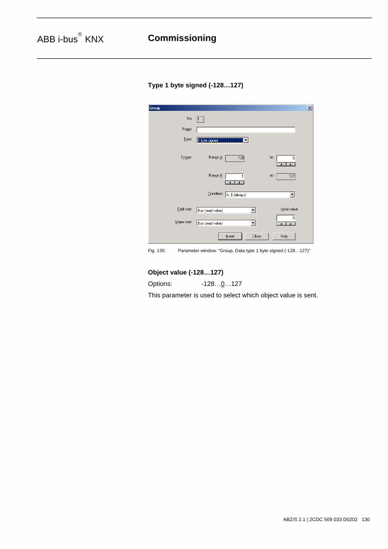
Commissioning
ABZ/S 2.1 | 2CDC 509 033 D0202 130
ABB i-bus KNX
Type 1 byte signed (-128…127)
Fig. 135: Parameter window: “Group, Data type 1 byte signed (-128…127)”
Object value (-128…127)
Options: -128…0…127
This parameter is used to select which object value is sent.

Commissioning
ABZ/S 2.1 | 2CDC 509 033 D0202 131
ABB i-bus KNX
Type 2 byte unsigned (0…65,535)
Fig. 136: Parameter window: “Group, Data type 2 byte unsigned (0…65,535)”
Object value (0…65,535)
Options: 0…65,535
This parameter is used to select which object value is sent.

Commissioning
ABZ/S 2.1 | 2CDC 509 033 D0202 132
ABB i-bus KNX
Type 2 byte signed (-32,768…32,767)
Fig. 137: Parameter window: “Group, Data type 2 byte signed (-32,768…32,767)”
Object value (-32,768…32,767)
Options: -32,768…0…32,767
This parameter is used to select which object value is sent.

Commissioning
ABZ/S 2.1 | 2CDC 509 033 D0202 133
ABB i-bus KNX
Type 2 byte floating point
Fig. 138: Parameter window: “Group, Data type 2 byte floating point”
Object value (-163.84…163.76) and Exponent 3 (Temp.)
Options: -163.84…0…163.76
This parameter is used to select which object value is sent.

Commissioning
ABZ/S 2.1 | 2CDC 509 033 D0202 134
ABB i-bus KNX
Exponent
Options: Auto / 0…3 (Temp.)…15
This parameter is used to select which exponent is assigned to the object value.
Note: Different object values can be set, depending on the exponent which is selected. The table below shows all the options.
Exponent Object value
Auto -671,088.64…0.00…670,760.96
0 -20.48…0.00…20.47
1 -40.96…0.00…40.94
2 -81.92…0.00…81.88
3 (Temp.) -163.84…0.00…163.76
4 -327.68…0.00…327.52
5 -655.36…0.00…655.04
6 -1,310.72…0.00…1,310.08
7 -2,621.44…0.00…2,620.16
8 -5,242.88…0.00…5,240.32
9 -10,485.76…0.00…10,480.64
10 -20,971.52…0.00…20,961.28
11 -41,943.04…0.00…41,922.56
12 -88,386.08…0.00…83,845.12
13 -167,772.16…0.00…167,690.24
14 -335,544.32…0.00…335,380.48
15 -671,088.64…0.00…670,760.96 Table 9: Exponent

Commissioning
ABZ/S 2.1 | 2CDC 509 033 D0202 135
ABB i-bus KNX
Condition
Options: A, B (always) / >A, >B (new entry) / A<>B (hysteresis)
The conditions for triggering a group are defined under Condition.
Option: A, B (always)
The entry A, B (always) means that the group is always triggered if the trigger value lies in Range A or Range B. If e.g. a telegram would be received several times with the same value or with values in the same range, the group would be triggered after each transmission.
If the temperature value of 21 °C is transmitted several times in succession, the group is activated each time and telegrams are thus sent each time to open the blinds and to switch off the air conditioning and lighting.
Option: >A, >B (new entry)
The entry >A, >B (new entry) means that the group is only triggered if the trigger value is located firstly in Range A or Range B. If the same value is sent several times to the Application Unit Time ABZ/S 2.1, the group is only triggered on the first transmission.
If the group was finally triggered by the transmission of a temperature value in Range A, e.g. 21 °C, then values were sent outside Range A e.g. 23 °C and then again a value in Range A such as 21 °C, the initial transmission of the value 21 °C activates the group and telegrams are sent to open the blinds and to switch off the air conditioning and lighting.

Commissioning
ABZ/S 2.1 | 2CDC 509 033 D0202 136
ABB i-bus KNX
Option: A< >B (hysteresis)
The entry A< >B (hysteresis) means that the group is only triggered if the trigger value is first located in Range A and the last triggering is carried out by a value in Range B or if the trigger value is first located in Range B and the last triggering is carried out by a value in Range A.
If the group was last triggered by the transmission of a value in Range A, e.g. 21 °C (the group is thereby activated e.g. to switch on the heating) and then values outside Range A have been transferred e.g. 23 °C followed by another value in Range A such as 21 °C, the group is no longer triggered by this value. The group can only be retriggered if a value is transmitted which lies in Range B i.e. above 24 °C (the group is thereby deactivated e.g. to switch off the heating).
Fig. 139: Example: Hysteresis, Group activated/deactivated

Commissioning
ABZ/S 2.1 | 2CDC 509 033 D0202 137
ABB i-bus KNX
Cold start
Options: Bus (read value) / Init (use initial value) / none (no reaction)
The behaviour of the Application Unit Time on bus voltage recovery is defined under Cold start.
Information that is currently stored in the Application Unit Time e.g. Group 1 triggered, is stored for at least 1 h on bus voltage failure. If the bus voltage failure lasts for longer than 1 h, the Application Unit Time automatically detects whether the information is still stored or whether there has been a data loss. The application program and the parameters are permanently stored in the Application Unit Time.
In the event of a data loss, the Application Unit Time carries out a so-called cold start on bus voltage recovery i.e. it can no longer access the stored data and must either work with preset data or read relevant data from other bus devices.
It should further be noted that the time switch program does not start automatically after a cold start as the current time or date are no longer available. See also Internal clock.
It can be defined how the Application Unit Time should react in the event of a cold start.
Option: Bus (read value)
After bus voltage recovery, the Application Unit Time reads out the relevant data from other bus devices. Depending on the value received and the criteria for triggering the group, it either triggers the group in Range A or Range B or it does not trigger the group.
Option: Init (use initial value)
The Application Unit Time uses preset values after bus voltage recovery. Depending on the preset values and the criteria for triggering the group, it either triggers the group in Range A or Range B or it does not trigger the group.
What is the initial value?
If the Application Unit Time should use a preset value after a bus voltage recovery with data loss i.e. after a cold start, this value is listed under Initial value.
Option: none (no reaction)
The Application Unit Time only triggers a group if a telegram with a value in Range A or Range B has been received.
The group is always triggered in principle after a cold start on receipt of the first value which lies in Range A or Range B.

Commissioning
ABZ/S 2.1 | 2CDC 509 033 D0202 138
ABB i-bus KNX
Warm start
Options: Bus (read value) / RAM (old value) / none (no reaction)
The behaviour of the Application Unit Time on bus voltage recovery is defined under Warm start.
Information that is currently stored in the Application Unit Time e.g. Group 1 triggered, is stored for at least 1 h on bus voltage failure. If the bus voltage failure lasts for longer than 1 h, the Application Unit Time automatically detects whether the information is still stored or whether there has been a data loss. The application program and the parameters are permanently stored in the Application Unit Time.
If the stored data is still available, the Application Unit Time carries out a so-called warm start on bus voltage recovery i.e. it can work with the stored data but it can also use preset data or read relevant data from other bus devices.
It can be defined how the Application Unit Time should react in the event of a warm start.
Option: Bus (read value)
After a bus voltage recovery, the Application Unit Time reads out the relevant data from other bus devices. Depending on the value received and the criteria for triggering the group, it either triggers the group in Range A or Range B or it does not trigger the group.
In the event of a warm start, a group e.g. is no longer triggered if this group was already activated in Range A and should be activated again in Range A after reading the other bus devices and the Trigger parameter is no longer set to A, B (always).
Option: RAM (old value)
After a bus voltage recovery, the Application Unit Time uses the stored values. Depending on the stored values i.e. the state prior to the bus voltage failure and the criteria for triggering the group, it either triggers the group in Range A or Range B or it does not trigger the group.
Option: none (no reaction)
The Application Unit Time only triggers a group if a telegram with a value in Range A or Range B has been received.
The group is always triggered in principle after a cold start on receipt of the first value which lies in Range A or Range B.
In the event of a warm start, the group is only triggered if all other criteria have been met e.g. the last value received prior to the bus failure was in Range B and the first value received after bus voltage recovery is in Range A.
Commissioning
ABZ/S 2.1 | 2CDC 509 033 D0202 139
ABB i-bus KNX
Initial value
Under Initial value, you define the value which the Application Unit Time should use as a preset value after a cold start. The field is dependent on the preset type e.g. if a 1-bit type has been selected, only the values 0 and 1 can be set.
“Insert” button
A new group is inserted via the Insert button.
“Close” button
The parameter window is closed via the Close button.
“Help” button
The “Help” file can be opened directly via the “Help” button and a further parameter window Help for application program… is opened.

Commissioning
ABZ/S 2.1 | 2CDC 509 033 D0202 140
ABB i-bus KNX
3.4.9.2 Edit group
Fig. 140: Dialog window: “Edit group”
To edit a group, select Groups in the selection area e.g. QU No. 01. The associated table is activated in the right-hand window.
The table is divided into QU No., QU Name, Type, Range A, Range B, Trigger, Warm start, Cold start and Init value.
The meaning of the individual columns is as follows:
QU No., QU Name, Type, Range A, Range B, Trigger
This table lists the consecutive numbers of the group (QU No.), the name of the group (QU Name), the type of the group trigger (Type), and the criteria for the Trigger in Range A and Range B.
Warm start, Cold start, Init value
This table lists the behaviour in the event of a Warm start and a Cold start as well as the associated Init value.
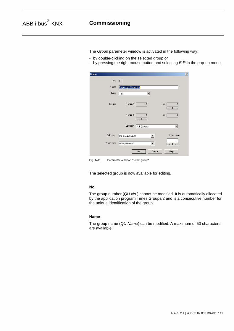
Commissioning
ABZ/S 2.1 | 2CDC 509 033 D0202 141
ABB i-bus KNX
The Group parameter window is activated in the following way:
- by double-clicking on the selected group or - by pressing the right mouse button and selecting Edit in the pop-up menu.
Fig. 141: Parameter window: “Select group”
The selected group is now available for editing.
No.
The group number (QU No.) cannot be modified. It is automatically allocated by the application program Times Groups/2 and is a consecutive number for the unique identification of the group.
Name
The group name (QU Name) can be modified. A maximum of 50 characters are available.

Commissioning
ABZ/S 2.1 | 2CDC 509 033 D0202 142
ABB i-bus KNX
Type
Options: 1 bit / 1 byte unsigned / 1 byte signed / 2 byte unsigned / 2 byte signed / 2 byte floating point
The type denotes which type of value is assigned to the trigger of a group (functional group) i.e. whether the group is triggered e.g. by a telegram with the binary value 1 or a telegram with the 1-byte value 128.
A group can be activated by a telegram with the group address of a group trigger of this group. Different types of values can be sent with a telegram e.g. 1-bit value i.e. binary values such as 0 and 1 or e.g. 1-byte values such as 0, 128 or 255, which can then be interpreted as 0%, 50% and 100%.
Trigger
The limits within which the values must lie to trigger the group are defined under Trigger for Range A and Range B. In the case of the 1-bit type, there are only the states 0 and 1. These values cannot be edited.
If a group is triggered by a group trigger, specific functions are activated e.g. switching the light on or off. The light can thereby be switched on in specific rooms e.g. by triggering a group with the value “0” and switched on in these rooms by triggering a group with the value “1”. A group can therefore behave in a different way when triggered by the value “0” than by the value “1”.
You could therefore also designate the triggering of a group by the value “1” as the activation of the group (functional group) and the triggering of the group by the value “0” as the deactivation of the group (functional group).
Binary values which trigger a group (functional group) can only adopt the values “0” and “1”. If the group is triggered e.g. by a 1-byte value, the triggered values can lie in a range between 0…255 or between 0%...100%.
Value ranges can therefore be entered for the activation of a group and for the deactivation of a group.
Commissioning
ABZ/S 2.1 | 2CDC 509 033 D0202 143
ABB i-bus KNX
Range A, Range B
Range A contains those values which activate or group or those values which trigger in Range A while Range B contains those values which deactivate a group or those values which trigger in Range B.
If a group is triggered e.g. by a 2-byte value with which the room temperature of a room is transmitted, the blinds could be opened e.g. by a temperature value under 22 °C and the air conditioning and lighting could be switched off. In the event of a temperature value above 24 °C, the blinds could be closed and the lighting and air conditioning could be switched on.
So that the group is not triggered each time e.g. after the multiple transmission of the same values i.e. to activate specific functions, further criteria for triggering the group can be defined.

Commissioning
ABZ/S 2.1 | 2CDC 509 033 D0202 144
ABB i-bus KNX
Note: Different options appear in the Trigger parameter, depending on which type has been selected.
Type 1 bit
Fig. 142: Parameter window: “Group, Data type 1 bit”
Object value (0…1)
Options: 0/1
This parameter is used to select which object value is sent.

Commissioning
ABZ/S 2.1 | 2CDC 509 033 D0202 145
ABB i-bus KNX
Type 1 byte unsigned (0…255)
Fig. 143: Parameter window: “Group, Data type 1 byte unsigned (0…255)”
Object value (0…255) and Standard
Options: 0…255
This parameter is used to select which object value is sent.
If Standard is also selected, the object value is issued without a unit of measurement.

Commissioning
ABZ/S 2.1 | 2CDC 509 033 D0202 146
ABB i-bus KNX
Type 1 byte unsigned (0…100%)
Fig. 144: Parameter window: “Group, Data type 1 byte unsigned (0…100%)”
Object value (0…100%) and in %
Options: 0.00…100%
This parameter is used to select which object value is sent.
If the option in % is also selected, 0 = 0% and 255 = 100% are assigned to the object values.

Commissioning
ABZ/S 2.1 | 2CDC 509 033 D0202 147
ABB i-bus KNX
Type 1 byte signed (-128…127)
Fig. 145: Parameter window: “Group, Data type 1 byte signed (-128…127)”
Object value (-128…127)
Options: -128…0…127
This parameter is used to select which object value is sent.

Commissioning
ABZ/S 2.1 | 2CDC 509 033 D0202 148
ABB i-bus KNX
Type 2 byte unsigned (0…65,535)
Fig. 146: Parameter window: “Group, Data type 2 byte unsigned (0…65,535)”
Object value (0…65,535)
Options: 0…65,535
This parameter is used to select which object value is sent.

Commissioning
ABZ/S 2.1 | 2CDC 509 033 D0202 149
ABB i-bus KNX
Type 2 byte signed (-32,768…32,767)
Fig. 147: Parameter window: “Group, Data type 2 byte signed (-32,768…32,767)”
Object value (-32,768…32,767)
Options: -32,768…0…32,767
This parameter is used to select which object value is sent.
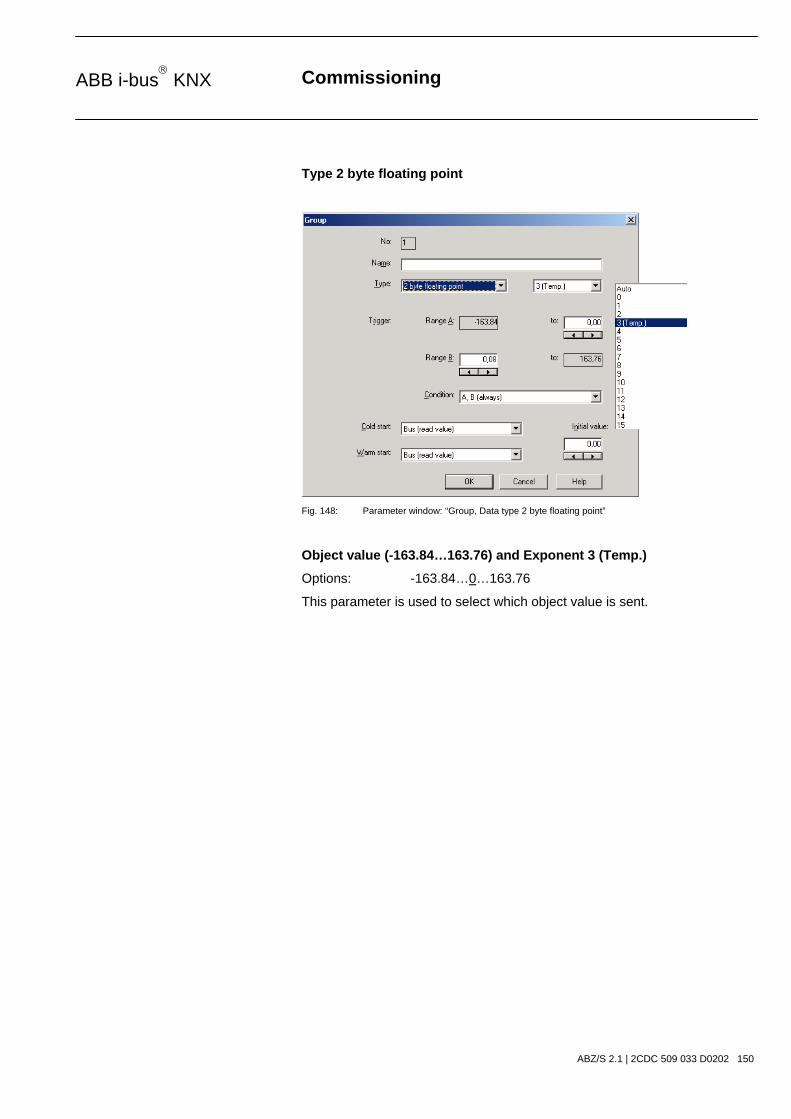
Commissioning
ABZ/S 2.1 | 2CDC 509 033 D0202 150
ABB i-bus KNX
Type 2 byte floating point
Fig. 148: Parameter window: “Group, Data type 2 byte floating point”
Object value (-163.84…163.76) and Exponent 3 (Temp.)
Options: -163.84…0…163.76
This parameter is used to select which object value is sent.

Commissioning
ABZ/S 2.1 | 2CDC 509 033 D0202 151
ABB i-bus KNX
Exponent
Options: Auto / 0…3 (Temp.)…15
This parameter is used to select which exponent is assigned to the object value.
Note: Different object values can be set, depending on the exponent which is selected. The table below shows all the options.
Exponent Object value
Auto -671,088.64…0.00…670,760.96
0 -20.48…0.00…20.47
1 -40.96…0.00…40.94
2 -81.92…0.00…81.88
3 (Temp.) -163.84…0.00…163.76
4 -327.68…0.00…327.52
5 -655.36…0.00…655.04
6 -1,310.72…0.00…1,310.08
7 -2,621.44…0.00…2,620.16
8 -5,242.88…0.00…5,240.32
9 -10,485.76…0.00…10,480.64
10 -20,971.52…0.00…20,961.28
11 -41,943.04…0.00…41,922.56
12 -88,386.08…0.00…83,845.12
13 -167,772.16…0.00…167,690.24
14 -335,544.32…0.00…335,380.48
15 -671,088.64…0.00…670,760.96 Table 10: Exponent
Commissioning
ABZ/S 2.1 | 2CDC 509 033 D0202 152
ABB i-bus KNX
Condition
Options: A, B (always) / >A, >B (new entry) / A<>B (hysteresis)
The conditions for triggering a group are defined under Condition.
Option: A, B (always)
The entry A, B (always) means that the group is always triggered if the trigger value lies in the range A or B. If e.g. a telegram would be received several times with the same value or with values in the same range, the group would be triggered after each transmission.
If the temperature value of 21 °C is transmitted several times in succession, the group is activated each time and telegrams are thus sent each time to open the blinds and to switch off the air conditioning and lighting.
Option: >A, >B (new entry)
The entry >A, >B (new entry) means that the group is only triggered if the trigger value is located firstly in Range A or Range B. If the same value is sent several times to the Application Unit Time ABZ/S 2.1, the group is only triggered on the first transmission.
If the group was finally triggered by the transmission of a temperature value in Range A, e.g. 21 °C, then values were sent outside Range A e.g. 23 °C and then again a value in Range A such as 21 °C, the initial transmission of the value 21 °C activates the group and telegrams are sent to open the blinds and to switch off the air conditioning and lighting.

Commissioning
ABZ/S 2.1 | 2CDC 509 033 D0202 153
ABB i-bus KNX
Option: A< >B (hysteresis)
The entry A< >B (hysteresis) means that the group is only triggered if the trigger value is first located in Range A and the last triggering is carried out by a value in Range B or if the trigger value is first located in Range B and the last triggering is carried out by a value in Range A.
If the group was last triggered by the transmission of a value in Range A, e.g. 21 °C (the group is thereby activated e.g. to switch on the heating) and then values outside Range A have been transferred e.g. 23 °C followed by another value in Range A such as 21 °C, the group is no longer triggered by this value. The group can only be retriggered if a value is transmitted which lies in Range B i.e. above 24 °C (the group is thereby deactivated e.g. to switch off the heating).
Fig. 149: Example: Hysteresis, Group activated/deactivated

Commissioning
ABZ/S 2.1 | 2CDC 509 033 D0202 154
ABB i-bus KNX
Cold start
Options: Bus (read value) / Init (use initial value) / none (no reaction)
The behaviour of the Application Unit Time on bus voltage recovery is defined under Cold start.
Information that is currently stored in the Application Unit Time e.g. Group 1 triggered, is stored for at least 1 h on bus voltage failure. If the bus voltage failure lasts for longer than 1 h, the Application Unit Time automatically detects whether the information is still stored or whether there has been a data loss. The application program and the parameters are permanently stored in the Application Unit Time.
In the event of a data loss, the Application Unit Time carries out a so-called cold start on bus voltage recovery i.e. it can no longer access the stored data and must either work with preset data or read relevant data from other bus devices.
It should further be noted that the time switch program does not start automatically after a cold start as the current time or date are no longer available. See also Internal clock.
It can be defined how the Application Unit Time should react in the event of a cold start.
Option: Bus (read value)
After bus voltage recovery, the Application Unit Time reads out the relevant data from other bus devices. Depending on the value received and the criteria for triggering the group, it either triggers the group in Range A or Range B or it does not trigger the group.
Option: Init (use initial value)
The Application Unit Time uses preset values after bus voltage recovery. Depending on the preset values and the criteria for triggering the group, it either triggers the group in Range A or Range B or it does not trigger the group.
What is the initial value?
If the Application Unit Time should use a preset value after a bus voltage recovery with data loss i.e. after a cold start, this value is listed under Initial value.
Option: none (no reaction)
The Application Unit Time only triggers a group if a telegram with a value in Range A or Range B has been received.
The group is always triggered in principle after a cold start on receipt of the first value which lies in Range A or Range B.

Commissioning
ABZ/S 2.1 | 2CDC 509 033 D0202 155
ABB i-bus KNX
Warm start
Options: Bus (read value) / RAM (old value) / none (no reaction)
The behaviour of the Application Unit Time on bus voltage recovery is defined under Warm start.
Information that is currently stored in the Application Unit Time e.g. Group 1 triggered, is stored for at least 1 h on bus voltage failure. If the bus voltage failure lasts for longer than 1 h, the Application Unit Time automatically detects whether the information is still stored or whether there has been a data loss. The application program and the parameters are permanently stored in the Application Unit Time.
If the stored data is still available, the Application Unit Time carries out a so-called warm start on bus voltage recovery i.e. it can work with the stored data but it can also use preset data or read relevant data from other bus devices.
It can be defined how the Application Unit Time should react in the event of a warm start.
Option: Bus (read value)
After a bus voltage recovery, the Application Unit Time reads out the relevant data from other bus devices. Depending on the value received and the criteria for triggering the group, it either triggers the group in Range A or Range B or it does not trigger the group.
In the event of a warm start, a group e.g. is no longer triggered if this group was already activated in Range A and should be activated again in Range A after reading the other bus devices and the Trigger parameter is no longer set to A, B (always).
Option: RAM (old value)
After a bus voltage recovery, the Application Unit Time uses the stored values. Depending on the stored values i.e. the state prior to the bus voltage failure and the criteria for triggering the group, it either triggers the group in Range A or Range B or it does not trigger the group.
Option: none (no reaction)
The Application Unit Time only triggers a group if a telegram with a value in Range A or Range B has been received.
The group is always triggered in principle after a cold start on receipt of the first value which lies in Range A or Range B.
In the event of a warm start, the group is only triggered if all other criteria have been met e.g. the last value received prior to the bus failure was in Range B and the first value received after bus voltage recovery is in Range A.

Commissioning
ABZ/S 2.1 | 2CDC 509 033 D0202 156
ABB i-bus KNX
Initial value
Under Initial value, you define the value which the Application Unit Time should use as a preset value after a cold start. The field is dependent on the preset type e.g. if a 1-bit type has been selected, only the values 0 and 1 can be set.
“Insert” button
A new group is inserted via the Insert button.
“Close” button
The parameter window is closed via the Close button.
“Help” button
The “Help” file can be opened directly via the “Help” button and a further parameter window Help for application program… is opened.

Commissioning
ABZ/S 2.1 | 2CDC 509 033 D0202 157
ABB i-bus KNX
3.4.9.3 Modify group
Fig. 150: Dialog window: “Modify group”
To modify a group, select Groups in the selection area followed by e.g. 01: Beginning of instruction. The associated parameter window is activated in the right-hand button as well as the Change button.
“Change” button
The Group parameter window becomes visible by pressing the Modify button. The settings can be modified there.

Commissioning
ABZ/S 2.1 | 2CDC 509 033 D0202 158
ABB i-bus KNX
The Group parameter window is activated in the following way:
- by clicking on the Change button.
Fig. 151: Parameter window: “Select group”
The selected group is now available for editing.
No.
The group number (QU No.) cannot be modified. It is automatically allocated by the application program Times Groups/2 and is a consecutive number for the unique identification of the group.
Name
The group name (QU Name) can be modified. A maximum of 50 characters are available.
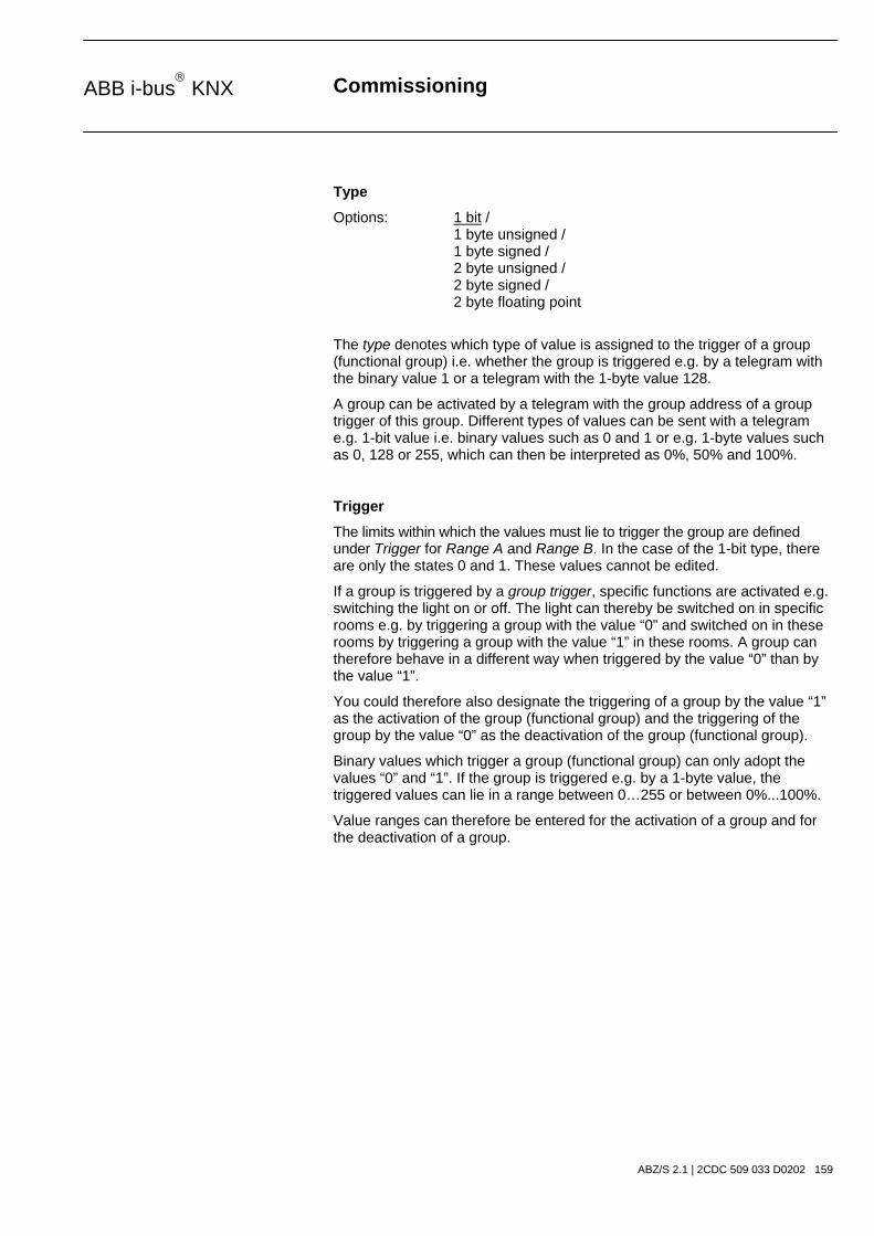
Commissioning
ABZ/S 2.1 | 2CDC 509 033 D0202 159
ABB i-bus KNX
Type
Options: 1 bit / 1 byte unsigned / 1 byte signed / 2 byte unsigned / 2 byte signed / 2 byte floating point
The type denotes which type of value is assigned to the trigger of a group (functional group) i.e. whether the group is triggered e.g. by a telegram with the binary value 1 or a telegram with the 1-byte value 128.
A group can be activated by a telegram with the group address of a group trigger of this group. Different types of values can be sent with a telegram e.g. 1-bit value i.e. binary values such as 0 and 1 or e.g. 1-byte values such as 0, 128 or 255, which can then be interpreted as 0%, 50% and 100%.
Trigger
The limits within which the values must lie to trigger the group are defined under Trigger for Range A and Range B. In the case of the 1-bit type, there are only the states 0 and 1. These values cannot be edited.
If a group is triggered by a group trigger, specific functions are activated e.g. switching the light on or off. The light can thereby be switched on in specific rooms e.g. by triggering a group with the value “0” and switched on in these rooms by triggering a group with the value “1” in these rooms. A group can therefore behave in a different way when triggered by the value “0” than by the value “1”.
You could therefore also designate the triggering of a group by the value “1” as the activation of the group (functional group) and the triggering of the group by the value “0” as the deactivation of the group (functional group).
Binary values which trigger a group (functional group) can only adopt the values “0” and “1”. If the group is triggered e.g. by a 1-byte value, the triggered values can lie in a range between 0…255 or between 0%...100%.
Value ranges can therefore be entered for the activation of a group and for the deactivation of a group.

Commissioning
ABZ/S 2.1 | 2CDC 509 033 D0202 160
ABB i-bus KNX
Range A, Range B
Range A contains those values which activate or group or those values which trigger in Range A while Range B contains those values which deactivate a group or those values which trigger in Range B.
If a group is triggered e.g. by a 2-byte value with which the room temperature of a room is transmitted, the blinds could be opened e.g. by a temperature value under 22 °C and the air conditioning and lighting could be switched off. In the event of a temperature value above 24 °C, the blinds could be closed and the lighting and air conditioning could be switched on.
So that the group is not triggered each time e.g. after the multiple transmission of the same values i.e. to activate specific functions, further criteria for triggering the group can be defined.

Commissioning
ABZ/S 2.1 | 2CDC 509 033 D0202 161
ABB i-bus KNX
Note: Different options appear in the Trigger parameter, depending on which type has been selected.
Type 1 bit
Fig. 152: Parameter window: “Group, Data type 1 bit”
Object value (0…1)
Options: 0/1
This parameter is used to select which object value is sent.

Commissioning
ABZ/S 2.1 | 2CDC 509 033 D0202 162
ABB i-bus KNX
Type 1 byte unsigned (0…255)
Fig. 153: Parameter window: “Group, Data type 1 byte unsigned (0…255)”
Object value (0…255) and Standard
Options: 0…255
This parameter is used to select which object value is sent.
If Standard is also selected, the object value is issued without a unit of measurement.

Commissioning
ABZ/S 2.1 | 2CDC 509 033 D0202 163
ABB i-bus KNX
Type 1 byte unsigned (0…100%)
Fig. 154: Parameter window: “Group, Data type 1 byte unsigned (0…100%)”
Object value (0…100%) and in %
Options: 0.00…100%
This parameter is used to select which object value is sent.
If the option in % is also selected, 0 = 0% and 255 = 100% are assigned to the object values.

Commissioning
ABZ/S 2.1 | 2CDC 509 033 D0202 164
ABB i-bus KNX
Type 1 byte signed (-128…127)
Fig. 155: Parameter window: “Group, Data type 1 byte signed (-128…127)”
Object value (-128…127)
Options: -128…0…127
This parameter is used to select which object value is sent.

Commissioning
ABZ/S 2.1 | 2CDC 509 033 D0202 165
ABB i-bus KNX
Type 2 byte unsigned (0…65,535)
Fig. 156: Parameter window: “Group, Data type 2 byte unsigned (0…65,535)”
Object value (0…65,535)
Options: 0…65,535
This parameter is used to select which object value is sent.

Commissioning
ABZ/S 2.1 | 2CDC 509 033 D0202 166
ABB i-bus KNX
Type 2 byte signed (-32,768…32,767)
Fig. 157: Parameter window: “Group, Data type 2 byte signed (-32,768…32,767)”
Object value (-32,768…32,767)
Options: -32,768…0…32,767
This parameter is used to select which object value is sent.

Commissioning
ABZ/S 2.1 | 2CDC 509 033 D0202 167
ABB i-bus KNX
Type 2 byte floating point
Fig. 158: Parameter window: “Group, Data type 2 byte floating point”
Object value (-163.84…163.76) and Exponent 3 (Temp.)
Options: -163.84…0…163.76
This parameter is used to select which object value is sent.

Commissioning
ABZ/S 2.1 | 2CDC 509 033 D0202 168
ABB i-bus KNX
Exponent
Options: Auto / 0…3 (Temp.)…15
This parameter is used to select which exponent is assigned to the object value.
Note: Different object values can be set, depending on the exponent which is selected. The table below shows all the options.
Exponent Object value
Auto -671,088.64…0.00…670,760.96
0 -20.48…0.00…20.47
1 -40.96…0.00…40.94
2 -81.92…0.00…81.88
3 (Temp.) -163.84…0.00…163.76
4 -327.68…0.00…327.52
5 -655.36…0.00…655.04
6 -1,310.72…0.00…1,310.08
7 -2,621.44…0.00…2,620.16
8 -5,242.88…0.00…5,240.32
9 -10,485.76…0.00…10,480.64
10 -20,971.52…0.00…20,961.28
11 -41,943.04…0.00…41,922.56
12 -88,386.08…0.00…83,845.12
13 -167,772.16…0.00…167,690.24
14 -335,544.32…0.00…335,380.48
15 -671,088.64…0.00…670,760.96 Table 11: Exponent

Commissioning
ABZ/S 2.1 | 2CDC 509 033 D0202 169
ABB i-bus KNX
Condition
Options: A, B (always) / >A, >B (new entry) / A<>B (hysteresis)
The conditions for triggering a group are defined under Condition.
Option: A, B (always)
The entry A, B (always) means that the group is always triggered if the trigger value lies in the range A or B. If e.g. a telegram would be received several times with the same value or with values in the same range, the group would be triggered after each transmission.
If the temperature value of 21 °C is transmitted several times in succession, the group is activated each time and telegrams are thus sent each time to open the blinds and to switch off the air conditioning and lighting.
Option: >A, >B (new entry)
The entry >A, >B (new entry) means that the group is only triggered if the trigger value is located firstly in Range A or Range B. If the same value is sent several times to the Application Unit Time ABZ/S 2.1, the group is only triggered on the first transmission.
If the group was finally triggered by the transmission of a temperature value in Range A, e.g. 21 °C, then values were sent outside Range A e.g. 23 °C and then again a value in Range A such as 21 °C, the initial transmission of the value 21 °C activates the group and telegrams are sent to open the blinds and to switch off the air conditioning and lighting.

Commissioning
ABZ/S 2.1 | 2CDC 509 033 D0202 170
ABB i-bus KNX
Option: A< >B (hysteresis)
The entry A< >B (hysteresis) means that the group is only triggered if the trigger value is first located in Range A and the last triggering is carried out by a value in Range B or if the trigger value is first located in Range B and the last triggering is carried out by a value in Range A.
If the group was last triggered by the transmission of a value in Range A, e.g. 21 °C (the group is thereby activated e.g. to switch on the heating) and then values outside Range A have been transferred e.g. 23 °C followed by another value in Range A such as 21 °C, the group is no longer triggered by this value. The group can only be retriggered if a value is transmitted which lies in Range B i.e. above 24 °C (the group is thereby deactivated e.g. to switch off the heating).
Fig. 159: Example: Hysteresis, Group activated/deactivated
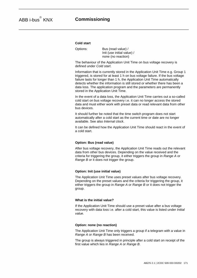
Commissioning
ABZ/S 2.1 | 2CDC 509 033 D0202 171
ABB i-bus KNX
Cold start
Options: Bus (read value) / Init (use initial value) / none (no reaction)
The behaviour of the Application Unit Time on bus voltage recovery is defined under Cold start.
Information that is currently stored in the Application Unit Time e.g. Group 1 triggered, is stored for at least 1 h on bus voltage failure. If the bus voltage failure lasts for longer than 1 h, the Application Unit Time automatically detects whether the information is still stored or whether there has been a data loss. The application program and the parameters are permanently stored in the Application Unit Time.
In the event of a data loss, the Application Unit Time carries out a so-called cold start on bus voltage recovery i.e. it can no longer access the stored data and must either work with preset data or read relevant data from other bus devices.
It should further be noted that the time switch program does not start automatically after a cold start as the current time or date are no longer available. See also Internal clock.
It can be defined how the Application Unit Time should react in the event of a cold start.
Option: Bus (read value)
After bus voltage recovery, the Application Unit Time reads out the relevant data from other bus devices. Depending on the value received and the criteria for triggering the group, it either triggers the group in Range A or Range B or it does not trigger the group.
Option: Init (use initial value)
The Application Unit Time uses preset values after bus voltage recovery. Depending on the preset values and the criteria for triggering the group, it either triggers the group in Range A or Range B or it does not trigger the group.
What is the initial value?
If the Application Unit Time should use a preset value after a bus voltage recovery with data loss i.e. after a cold start, this value is listed under Initial value.
Option: none (no reaction)
The Application Unit Time only triggers a group if a telegram with a value in Range A or Range B has been received.
The group is always triggered in principle after a cold start on receipt of the first value which lies in Range A or Range B.

Commissioning
ABZ/S 2.1 | 2CDC 509 033 D0202 172
ABB i-bus KNX
Warm start
Options: Bus (read value) / RAM (old value) / none (no reaction)
The behaviour of the Application Unit Time on bus voltage recovery is defined under Warm start.
Information that is currently stored in the Application Unit Time e.g. Group 1 triggered, is stored for at least 1 h on bus voltage failure. If the bus voltage failure lasts for longer than 1 h, the Application Unit Time automatically detects whether the information is still stored or whether there has been a data loss. The application program and the parameters are permanently stored in the Application Unit Time.
If the stored data is still available, the Application Unit Time carries out a so-called warm start on bus voltage recovery i.e. it can work with the stored data but it can also use preset data or read relevant data from other bus devices.
It can be defined how the Application Unit Time should react in the event of a warm start.
Option: Bus (read value)
After a bus voltage recovery, the Application Unit Time reads out the relevant data from other bus devices. Depending on the value received and the criteria for triggering the group, it either triggers the group in Range A or Range B or it does not trigger the group.
In the event of a warm start, a group e.g. is no longer triggered if this group was already activated in Range A and should be activated again in Range A after reading the other bus devices and the Trigger parameter is no longer set to A, B (always).
Option: RAM (old value)
After a bus voltage recovery, the Application Unit Time uses the stored values. Depending on the stored values i.e. the state prior to the bus voltage failure and the criteria for triggering the group, it either triggers the group in Range A or Range B or it does not trigger the group.
Option: none (no reaction)
The Application Unit Time only triggers a group if a telegram with a value in Range A or Range B has been received.
The group is always triggered in principle after a cold start on receipt of the first value which lies in Range A or Range B.
In the event of a warm start, the group is only triggered if all other criteria have been met e.g. the last value received prior to the bus failure was in Range B and the first value received after bus voltage recovery is in Range A.

Commissioning
ABZ/S 2.1 | 2CDC 509 033 D0202 173
ABB i-bus KNX
Initial value
Under Initial value, you define the value which the Application Unit Time should use as a preset value after a cold start. The field is dependent on the preset type e.g. if a 1-bit type has been selected, only the values 0 and 1 can be set.
“Insert” button
A new group is inserted via the Insert button.
“Close” button
The parameter window is closed via the Close button.
“Help” button
The “Help” file can be opened directly via the “Help” button and a further parameter window Help for application program… is opened.

Commissioning
ABZ/S 2.1 | 2CDC 509 033 D0202 174
ABB i-bus KNX
3.4.10 Group trigger - General
Fig. 160: Dialog window: “Group trigger - General”
The created triggers are shown in the folder Groups, 01: Beginning of instruction and Trigger.
Group triggers trigger a group if
- the Application Unit Time receives a telegram whose group address has been entered in the list of group triggers
- its value lies in the ranges which have been defined for triggering a group and
- its value meets the criteria for triggering a group.
When triggering a group through the time switch program of the Application Unit Time, the time switch program sends a telegram with a group address which is simultaneously received by the Application Unit Time and thus triggers the group.
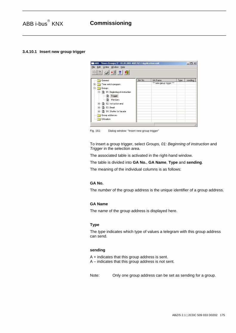
Commissioning
ABZ/S 2.1 | 2CDC 509 033 D0202 175
ABB i-bus KNX
3.4.10.1 Insert new group trigger
Fig. 161: Dialog window: “Insert new group trigger”
To insert a group trigger, select Groups, 01: Beginning of instruction and Trigger in the selection area.
The associated table is activated in the right-hand window.
The table is divided into GA No., GA Name, Type and sending.
The meaning of the individual columns is as follows:
GA No.
The number of the group address is the unique identifier of a group address.
GA Name
The name of the group address is displayed here.
Type
The type indicates which type of values a telegram with this group address can send.
sending
A + indicates that this group address is sent. A – indicates that this group address is not sent.
Note: Only one group address can be set as sending for a group.

Commissioning
ABZ/S 2.1 | 2CDC 509 033 D0202 176
ABB i-bus KNX
The dialog window Trigger for group 01: Beginning of instruction is activated in the following way:
- by double-clicking on *** new group trigger *** or - by pressing the right mouse button and selecting New group trigger in the pop-up menu or - by selecting Edit in the menu bar and then activating New group trigger in the pop-up menu.
Fig. 162: Parameter window: “Trigger for group 01: Beginning of instruction, Insert group address”
Group address
Options: new group address
The parameter is divided into Type, Name and No. The table can be arranged and sorted as required.
The meaning of the individual columns is as follows:
Type
The type indicates which type of values a telegram with this group address can send.
Name
The name of the group address is defined during the parameterisation of the ABB i-bus® installation and cannot be modified with the parameterisation software PZM2.
No.
The number of the group address is the unique identifier of a group address.

Commissioning
ABZ/S 2.1 | 2CDC 509 033 D0202 177
ABB i-bus KNX
After selecting the option new group address, the associated dialog window Add group addresses is activated.
Fig. 163: Dialog window: “Group trigger, Insert group addresses”
The main group, middle group and the subgroup are created in sequence via drag & drop.
Fig. 164: Parameter window: “Group trigger, Create main group, middle group and subgroup”
Note: The function descriptions and screenshots of the application program in this product manual all relate to ETS3. The application program for ETS4 has now become available.
The only difference between both program versions is the number of possible main groups: ETS3 = up to 15 main groups ETS4 = up to 31 main groups
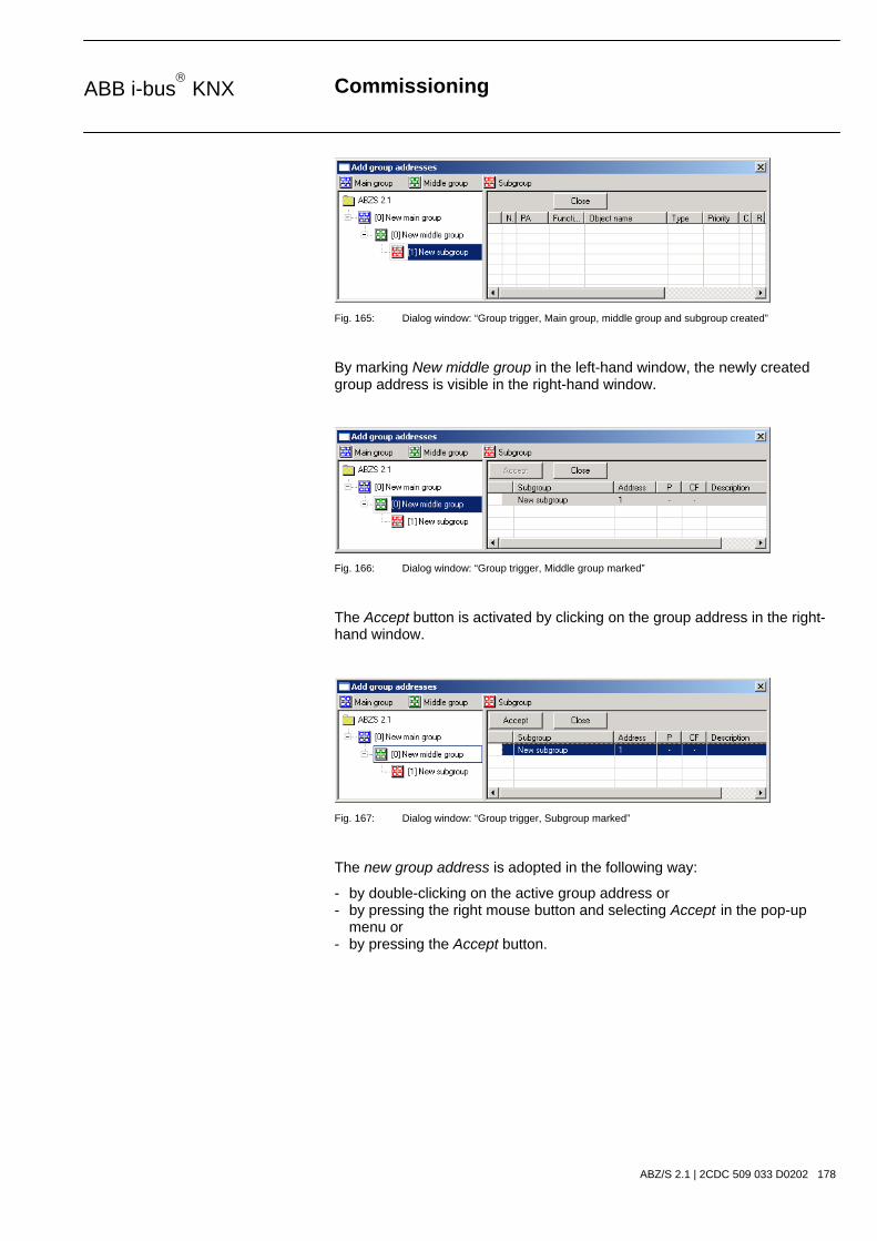
Commissioning
ABZ/S 2.1 | 2CDC 509 033 D0202 178
ABB i-bus KNX
Fig. 165: Dialog window: “Group trigger, Main group, middle group and subgroup created”
By marking New middle group in the left-hand window, the newly created group address is visible in the right-hand window.
Fig. 166: Dialog window: “Group trigger, Middle group marked”
The Accept button is activated by clicking on the group address in the right-hand window.
Fig. 167: Dialog window: “Group trigger, Subgroup marked”
The new group address is adopted in the following way:
- by double-clicking on the active group address or - by pressing the right mouse button and selecting Accept in the pop-up menu or - by pressing the Accept button.
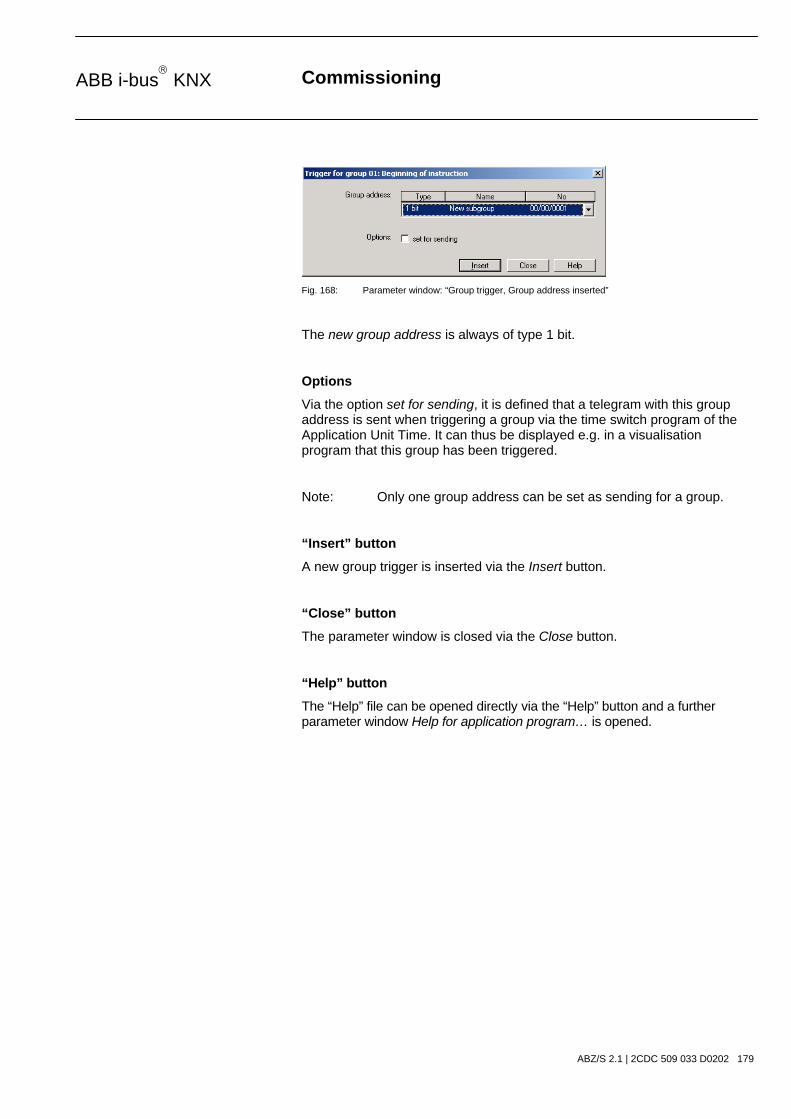
Commissioning
ABZ/S 2.1 | 2CDC 509 033 D0202 179
ABB i-bus KNX
Fig. 168: Parameter window: “Group trigger, Group address inserted”
The new group address is always of type 1 bit.
Options
Via the option set for sending, it is defined that a telegram with this group address is sent when triggering a group via the time switch program of the Application Unit Time. It can thus be displayed e.g. in a visualisation program that this group has been triggered.
Note: Only one group address can be set as sending for a group.
“Insert” button
A new group trigger is inserted via the Insert button.
“Close” button
The parameter window is closed via the Close button.
“Help” button
The “Help” file can be opened directly via the “Help” button and a further parameter window Help for application program… is opened.

Commissioning
ABZ/S 2.1 | 2CDC 509 033 D0202 180
ABB i-bus KNX
3.4.10.2 Edit group trigger
Fig. 169: Dialog window: “Edit group trigger”
To edit a group trigger, select Groups, 01: Beginning of instruction and Trigger in the selection area.
The associated table is activated in the right-hand window.
The table is divided into GA No., GA Name, Type and sending.
The meaning of the individual columns is as follows:
GA No.
The number of the group address is the unique identifier of a group address.
GA Name
The name of the group address is displayed here.
Type
The type indicates which type of values a telegram with this group address can send.
sending
A + indicates that this group address is sent. A – indicates that this group address is not sent.
Note: Only one group address can be set as sending for a group.

Commissioning
ABZ/S 2.1 | 2CDC 509 033 D0202 181
ABB i-bus KNX
Select an existing trigger e.g. the group address 00/00/002. The dialog window for the selected Trigger for group 01: Beginning of instruction is activated in the following way:
- by double-clicking on the selected trigger or - by pressing the right mouse button and selecting Edit in the pop-up menu.
Fig. 170: Parameter window: “Edit group trigger”
The selected trigger dialog is now available for editing.
Group address
Options: existing group addresses / new group address
An existing group address can be assigned in the selection list.
The parameter is divided into Type, Name and No. The table can be arranged and sorted as required.
The meaning of the individual columns is as follows:
Type
The type indicates which type of values a telegram with this group address can send.
Name
The name of the group address is defined when configuring the ABB i-bus® installation and cannot be modified with the parameterisation software PZM2.
No.
The number of the group address is the unique identifier of a group address.
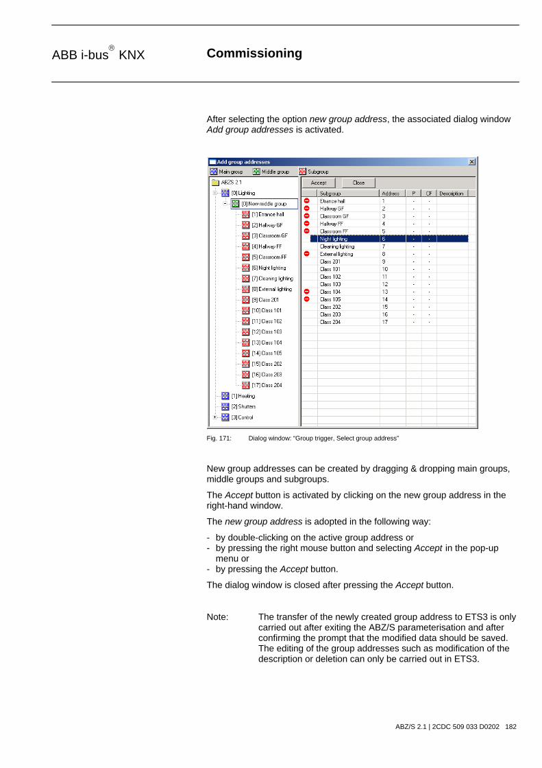
Commissioning
ABZ/S 2.1 | 2CDC 509 033 D0202 182
ABB i-bus KNX
After selecting the option new group address, the associated dialog window Add group addresses is activated.
Fig. 171: Dialog window: “Group trigger, Select group address”
New group addresses can be created by dragging & dropping main groups, middle groups and subgroups.
The Accept button is activated by clicking on the new group address in the right-hand window.
The new group address is adopted in the following way:
- by double-clicking on the active group address or - by pressing the right mouse button and selecting Accept in the pop-up menu or - by pressing the Accept button.
The dialog window is closed after pressing the Accept button.
Note: The transfer of the newly created group address to ETS3 is only carried out after exiting the ABZ/S parameterisation and after confirming the prompt that the modified data should be saved. The editing of the group addresses such as modification of the description or deletion can only be carried out in ETS3.

Commissioning
ABZ/S 2.1 | 2CDC 509 033 D0202 183
ABB i-bus KNX
Options
Via the option set for sending, it is defined that a telegram with this group address is sent when triggering a group via the time switch program of the Application Unit Time. It can thus be displayed e.g. in a visualisation program that this group has been triggered.
Note: Only one group address can be set as sending for a group.
“OK” button
When the “OK” button is pressed, the settings are adopted and the parameter window closes.
“Cancel” button
When the “Cancel” button is pressed, the function is aborted and the parameter window closes.
“Help” button
The “Help” file can be opened directly via the “Help” button and a further parameter window Help for application program… is opened.

Commissioning
ABZ/S 2.1 | 2CDC 509 033 D0202 184
ABB i-bus KNX
3.4.10.3 Delete group trigger
Fig. 172: Dialog window: “Delete group trigger”
To delete a group trigger, select Groups, 01: Beginning of instruction and Trigger in the selection area.
The table is divided into GA No., GA Name, Type and sending.
The meaning of the individual columns is as follows:
GA No.
The number of the group address is the unique identifier of a group address.
GA Name
The name of the group address is displayed here.
Type
The type indicates which type of values a telegram with this group address can send.
sending
A + indicates that this group address is sent. A – indicates that this group address is not sent.
Note: Only one group address can be set as sending for a group.

Commissioning
ABZ/S 2.1 | 2CDC 509 033 D0202 185
ABB i-bus KNX
Select the group address which should be deleted e.g. GA No. 00/00/002.
Fig. 173: Dialog window: “Select group trigger”
The selected group address is deleted in the following way:
- by pressing the Del button or - by pressing the right mouse button and selecting Delete in the pop-up menu or - by selecting Edit in the menu bar and then activating Delete in the pop-up menu.
“Yes” button
Before the group trigger can be deleted, a prompt must be confirmed with Yes.
Fig. 174: Parameter window: “Group trigger, Prompt”
“No” button
The group trigger is not deleted when the No button is pressed.
“Cancel” button
When the “Cancel” button is pressed, the function is aborted and the parameter window closes.
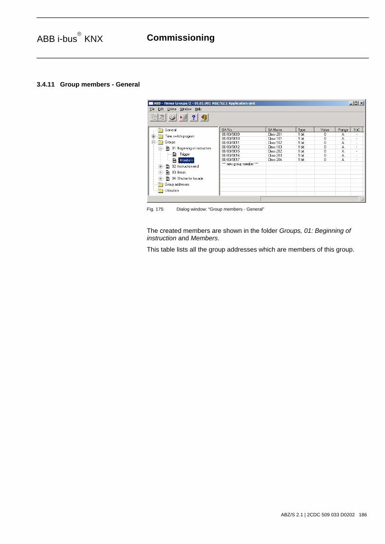
Commissioning
ABZ/S 2.1 | 2CDC 509 033 D0202 186
ABB i-bus KNX
3.4.11 Group members - General
Fig. 175: Dialog window: “Group members - General”
The created members are shown in the folder Groups, 01: Beginning of instruction and Members.
This table lists all the group addresses which are members of this group.

Commissioning
ABZ/S 2.1 | 2CDC 509 033 D0202 187
ABB i-bus KNX
3.4.11.1 Insert new group member
Fig. 176: Dialog window: “Insert new group member”
To insert a group member, select Groups, 01: Beginning of instruction and Members in the selection area.
The associated table is activated in the right-hand window.
The table is divided into GA No., GA Name, Type, Value, Range and SoC.
The meaning of the individual columns is as follows:
GA No.
The number of the group address is the unique identifier of a group address.
GA Name
The name of the group address is displayed here.
Type
The type indicates which type of values a telegram with this group address can send.
Value
The value which is transmitted when triggering the group with this group address is displayed under Value.

Commissioning
ABZ/S 2.1 | 2CDC 509 033 D0202 188
ABB i-bus KNX
Range
The entry under Range defines whether this value is transmitted when triggering the group in range A or range B.
SoC (Send on Change)
A tick in the SoC column indicates that a telegram is only sent if the value differs from the last value that was sent e.g. if the light should be switched on and is already switched on, this telegram is not sent.
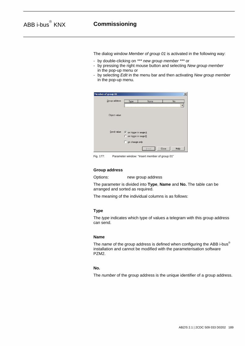
Commissioning
ABZ/S 2.1 | 2CDC 509 033 D0202 189
ABB i-bus KNX
The dialog window Member of group 01 is activated in the following way:
- by double-clicking on *** new group member *** or - by pressing the right mouse button and selecting New group member in the pop-up menu or - by selecting Edit in the menu bar and then activating New group member in the pop-up menu.
Fig. 177: Parameter window: “Insert member of group 01”
Group address
Options: new group address
The parameter is divided into Type, Name and No. The table can be arranged and sorted as required.
The meaning of the individual columns is as follows:
Type
The type indicates which type of values a telegram with this group address can send.
Name
The name of the group address is defined when configuring the ABB i-bus® installation and cannot be modified with the parameterisation software PZM2.
No.
The number of the group address is the unique identifier of a group address.

Commissioning
ABZ/S 2.1 | 2CDC 509 033 D0202 190
ABB i-bus KNX
After selecting the option new group address, the associated dialog window Add group addresses is activated.
Fig. 178: Dialog window: “Group member, Add group addresses”
The main group, middle group and the subgroup are created in sequence via drag & drop.
Fig. 179: Parameter window: “Group member, Create new main group, middle group and subgroup”
Note: The function descriptions and screenshots of the application program in this product manual all relate to ETS3. The application program for ETS4 has now become available.
The only difference between both program versions is the number of possible main groups: ETS3 = up to 15 main groups ETS4 = up to 31 main groups

Commissioning
ABZ/S 2.1 | 2CDC 509 033 D0202 191
ABB i-bus KNX
Fig. 180: Dialog window: “Group member, Main group, middle group and subgroup created”
By marking New middle group in the left-hand window, the newly created group address is visible in the right-hand window.
Fig. 181: Dialog window: “Group member, Middle group marked”
The Accept button is activated by clicking on the group address in the right-hand window.
Fig. 182: Dialog window: “Group member, Subgroup marked”
The new group address is adopted in the following way:
- by double-clicking on the active group address or - by pressing the right mouse button and selecting Accept in the pop-up menu or - by pressing the Accept button.

Commissioning
ABZ/S 2.1 | 2CDC 509 033 D0202 192
ABB i-bus KNX
After pressing the Accept button, a further dialog window Group address becomes active. The data type for the newly created group address is selected in this window.
Fig. 183: Parameter window: “Group member, Select data type”
“OK” button
When the “OK” button is pressed, the settings are adopted and the parameter window closes.
“Cancel” button
When the “Cancel” button is pressed, the function is aborted and the parameter window closes.
“Help” button
The “Help” file can be opened directly via the “Help” button and a further parameter window Help for application program… is opened.
Note: The transfer of the newly created group address to ETS3 is only carried out after exiting the ABZ/S parameterisation and after confirming the prompt that the modified data should be saved. The editing of the group addresses such as modification of the description or deletion can only be carried out in ETS3.

Commissioning
ABZ/S 2.1 | 2CDC 509 033 D0202 193
ABB i-bus KNX
Note: Different options appear in the Object value parameter depending on the type which has been selected for the group address.
Type 1 bit
Fig. 184: Parameter window: “Group member, Data type 1 bit”
Object value (0…1)
Options: 0/1
This parameter is used to select which object value is sent.

Commissioning
ABZ/S 2.1 | 2CDC 509 033 D0202 194
ABB i-bus KNX
Type 2 bit priority
Fig. 185: Parameter window: “Group member, Data type 2 bit priority”
Object value
Options: Free/ Forced ON/ Forced OFF
This parameter is used to select which object value is sent. The priority control function is explained in the following table:
Bit 1 Bit 0 Access Description
0 0 Free
0 1 Free
The priority object has enabled e.g. the switch actuator. The output switches depending on the value of the switch object.
1 0 OFF The priority object has switched e.g. the switch actuator OFF with priority control. The switch object has no function.
1 1 ON The priority object has switched e.g. the switch actuator ON with priority control. The switch object has no function.
Table 12: Priority object
Note: 4 different values can be sent with the telegram. So-called priority objects can thus be addressed in the EIB devices. If a channel e.g. in a switch actuator should switch on or off, the value 1 or 0 is sent to the assigned switch object. If a priority object is also assigned to this channel, the value that was sent to the priority object defines the behaviour of the channel.

Commissioning
ABZ/S 2.1 | 2CDC 509 033 D0202 195
ABB i-bus KNX
Type 1 byte unsigned (0…255)
Fig. 186: Parameter window: “Group member, Data type 1 byte unsigned (0…255)”
Object value (0…255) and Standard
Options: 0…255
This parameter is used to select which object value is sent.
If Standard is also selected, the object value is issued without a unit of measurement.
Type 1 byte unsigned (0…100%)
Fig. 187: Parameter window: “Group member, Data type 1 byte unsigned (0…100%)”
Object value (0…100%) and in %
Options: 0.00…100%
This parameter is used to select which object value is sent.
If the option in % is also selected, 0 = 0% and 255 = 100% are assigned to the object values.

Commissioning
ABZ/S 2.1 | 2CDC 509 033 D0202 196
ABB i-bus KNX
Type 1 byte signed (-128…127)
Fig. 188: Parameter window: “Group member, Data type 1 byte signed (-128…127)”
Object value (-128…127)
Options: -128…0…127
This parameter is used to select which object value is sent.
Type 2 byte unsigned (0…65,535)
Fig. 189: Parameter window: “Group member, Data type 2 byte unsigned (0…65,535)”
Object value (0…65,535)
Options: 0…65,535
This parameter is used to select which object value is sent.

Commissioning
ABZ/S 2.1 | 2CDC 509 033 D0202 197
ABB i-bus KNX
Type 2 byte signed (-32,768…32,767)
Fig. 190: Parameter window: “Group member, Data type 2 byte signed (-32,768…32,767)”
Object value (-32,768…32,767)
Options: -32,768…0…32,767
This parameter is used to select which object value is sent.
Type 2 byte floating point
Fig. 191: Parameter window: “Group member, Data type 2 byte floating point”
Object value (-163.84…163.76) and Exponent 3 (Temp.)
Options: -163.84…0…163.76
This parameter is used to select which object value is sent.

Commissioning
ABZ/S 2.1 | 2CDC 509 033 D0202 198
ABB i-bus KNX
Exponent
Options: Auto / 0…3 (Temp.)…15
This parameter is used to select which exponent is assigned to the object value.
Note: Different object values can be set, depending on the exponent which is selected. The table below shows all the options.
Exponent Object value
Auto -671,088.64…0.00…670,760.96
0 -20.48…0.00…20.47
1 -40.96…0.00…40.94
2 -81.92…0.00…81.88
3 (Temp.) -163.84…0.00…163.76
4 -327.68…0.00…327.52
5 -655.36…0.00…655.04
6 -1,310.72…0.00…1,310.08
7 -2,621.44…0.00…2,620.16
8 -5,242.88…0.00…5,240.32
9 -10,485.76…0.00…10,480.64
10 -20,971.52…0.00…20,961.28
11 -41,943.04…0.00…41,922.56
12 -88,386.08…0.00…83,845.12
13 -167,772.16…0.00…167,690.24
14 -335,544.32…0.00…335,380.48
15 -671,088.64…0.00…670,760.96 Table 13: Exponent

Commissioning
ABZ/S 2.1 | 2CDC 509 033 D0202 199
ABB i-bus KNX
Send value
Options: on trigger in range A / on trigger in range B
The value which should be sent can be defined for each range via the option on trigger in range A or on trigger in range B.
only on change
A tick in the entry only on change means that a telegram is only sent if the value has changed e.g. if the light was already switched on and should still be switched on, this telegram is not sent.
“Insert” button
A new group member is inserted via the Insert button.
“Close” button
The parameter window is closed via the Close button.
“Help” button
The “Help” file can be opened directly via the “Help” button and a further parameter window Help for application program… is opened.
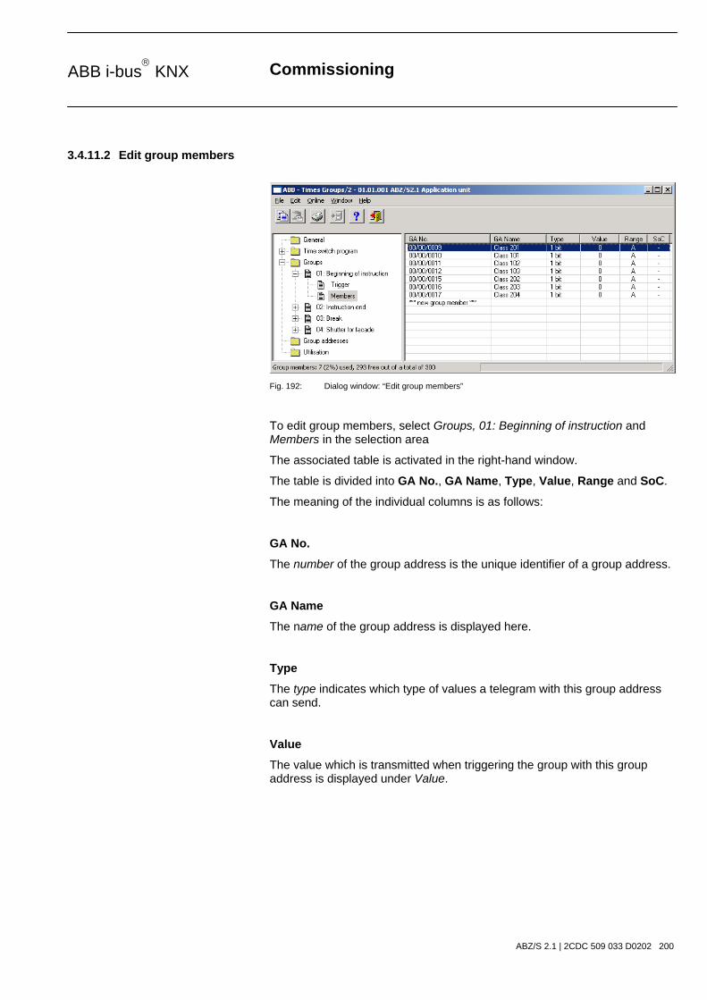
Commissioning
ABZ/S 2.1 | 2CDC 509 033 D0202 200
ABB i-bus KNX
3.4.11.2 Edit group members
Fig. 192: Dialog window: “Edit group members”
To edit group members, select Groups, 01: Beginning of instruction and Members in the selection area
The associated table is activated in the right-hand window.
The table is divided into GA No., GA Name, Type, Value, Range and SoC.
The meaning of the individual columns is as follows:
GA No.
The number of the group address is the unique identifier of a group address.
GA Name
The name of the group address is displayed here.
Type
The type indicates which type of values a telegram with this group address can send.
Value
The value which is transmitted when triggering the group with this group address is displayed under Value.

Commissioning
ABZ/S 2.1 | 2CDC 509 033 D0202 201
ABB i-bus KNX
Range
The entry under Range defines whether this value is transmitted when triggering the group in range A or range B.
SoC (Send on Change)
A tick in the SoC column indicates that a telegram is only sent if the value differs from the last value that was sent e.g. if the light should be switched on and is already switched on, this telegram is not sent.

Commissioning
ABZ/S 2.1 | 2CDC 509 033 D0202 202
ABB i-bus KNX
Select an existing member e.g. the group address 00/00/009. The dialog window for the selected Member of group 01 is activated in the following way:
- by double-clicking on the selected member or - by pressing the right mouse button and selecting Edit in the pop-up menu.
Fig. 193: Parameter window: “Select member for group 01”
The selected member dialog is available for editing.
Group address (trigger via bus)
Options: existing group address / new group address
An existing group address can be assigned in the selection list.
The parameter is divided into Type, Name and No. The table can be arranged and sorted as required.
The meaning of the individual columns is as follows:
Type
The type indicates which type of values a telegram with this group address can send.
Name
The name of the group address is defined when configuring the ABB i-bus® installation and cannot be modified with the parameterisation software PZM2.
No.
The number of the group address is the unique identifier of a group address.

Commissioning
ABZ/S 2.1 | 2CDC 509 033 D0202 203
ABB i-bus KNX
After selecting the option new group address, the associated dialog window Add group addresses is activated.
Fig. 194: Dialog window: “Group member, Select group address”
The main group, middle group and the subgroup are created in sequence via drag & drop.
The Accept button is activated by clicking on the group address in the right-hand window.
The new group address is adopted in the following way:
- by double-clicking on the active group address or - by pressing the right mouse button and selecting Accept in the pop-up menu or - by pressing the Accept button.

Commissioning
ABZ/S 2.1 | 2CDC 509 033 D0202 204
ABB i-bus KNX
After pressing the Accept button, a further dialog window Group address becomes active. The data type for the newly created group address is selected in this window.
Fig. 195: Parameter window: “Group member, Select data type”
“OK” button
When the “OK” button is pressed, the settings are adopted and the parameter window closes.
“Cancel” button
When the “Cancel” button is pressed, the function is aborted and the parameter window closes.
“Help” button
The “Help” file can be opened directly via the “Help” button and a further parameter window Help for application program… is opened.
Note: The transfer of the newly created group address to ETS3 is only carried out after exiting the ABZ/S parameterisation and after confirming the prompt that the modified data should be saved. The editing of the group addresses such as modification of the description or deletion can only be carried out in ETS3.

Commissioning
ABZ/S 2.1 | 2CDC 509 033 D0202 205
ABB i-bus KNX
Note: Different options appear in the Object value parameter depending on the type which has been selected for the group address.
Type 1 bit
Fig. 196: Parameter window: “Group member, Data type 1 bit”
Object value (0…1)
Options: 0/1
This parameter is used to select which object value is sent.

Commissioning
ABZ/S 2.1 | 2CDC 509 033 D0202 206
ABB i-bus KNX
Type 2 bit priority
Fig. 197: Parameter window: “Group member, Data type 2 bit priority”
Object value
Options: Free/ Forced ON/ Forced OFF
This parameter is used to select which object value is sent. The priority control function is explained in the following table:
Bit 1 Bit 0 Access Description
0 0 Free
0 1 Free
The priority object has enabled e.g. the switch actuator. The output switches depending on the value of the switch object.
1 0 OFF The priority object has switched e.g. the switch actuator OFF with priority control. The switch object has no function.
1 1 ON The priority object has switched e.g. the switch actuator ON with priority control. The switch object has no function.
Table 14: Priority object
Note: 4 different values can be sent with the telegram. So-called priority objects can thus be addressed in the EIB devices. If a channel e.g. in a switch actuator should switch on or off, the value 1 or 0 is sent to the assigned switch object. If a priority object is also assigned to this channel, the value that was sent to the priority object defines the behaviour of the channel.

Commissioning
ABZ/S 2.1 | 2CDC 509 033 D0202 207
ABB i-bus KNX
Type 1 byte unsigned (0…255)
Fig. 198: Parameter window: “Group member, Data type 1 byte unsigned (0…255)”
Object value (0…255) and Standard
Options: 0…255
This parameter is used to select which object value is sent.
If Standard is also selected, the object value is issued without a unit of measurement.
Type 1 byte unsigned (0…100%)
Fig. 199: Parameter window: “Group member, Data type 1 byte unsigned (0…100%)”
Object value (0…100%) and in %
Options: 0.00…100%
This parameter is used to select which object value is sent.
If the option in % is also selected, 0 = 0% and 255 = 100% are assigned to the object values.

Commissioning
ABZ/S 2.1 | 2CDC 509 033 D0202 208
ABB i-bus KNX
Type 1 byte signed (-128…127)
Fig. 200: Parameter window: “Group member, Data type 1 byte signed (-128…127)”
Object value (-128…127)
Options: -128…0…127
This parameter is used to select which object value is sent.
Type 2 byte unsigned (0…65,535)
Fig. 201: Parameter window: “Group member, Data type 2 byte unsigned (0…65,535)”
Object value (0…65,535)
Options: 0…65,535
This parameter is used to select which object value is sent.

Commissioning
ABZ/S 2.1 | 2CDC 509 033 D0202 209
ABB i-bus KNX
Type 2 byte signed (-32,768…32,767)
Fig. 202: Parameter window: “Group member, Data type 2 byte signed (-32,768…32,767)”
Object value (-32,768…32,767)
Options: -32,768…0…32,767
This parameter is used to select which object value is sent.
Type 2 byte floating point
Fig. 203: Parameter window: “Group member, Data type 2 byte floating point”
Object value (-163.84…163.76) and Exponent 3 (Temp.)
Options: -163.84…0…163.76
This parameter is used to select which object value is sent.

Commissioning
ABZ/S 2.1 | 2CDC 509 033 D0202 210
ABB i-bus KNX
Exponent
Options: Auto / 0…3 (Temp.)…15
This parameter is used to select which exponent is assigned to the object value.
Note: Different object values can be set, depending on the exponent which is selected. The table below shows all the options.
Exponent Object value
Auto -671,088.64…0.00…670,760.96
0 -20.48…0.00…20.47
1 -40.96…0.00…40.94
2 -81.92…0.00…81.88
3 (Temp.) -163.84…0.00…163.76
4 -327.68…0.00…327.52
5 -655.36…0.00…655.04
6 -1,310.72…0.00…1,310.08
7 -2,621.44…0.00…2,620.16
8 -5,242.88…0.00…5,240.32
9 -10,485.76…0.00…10,480.64
10 -20,971.52…0.00…20,961.28
11 -41,943.04…0.00…41,922.56
12 -88,386.08…0.00…83,845.12
13 -167,772.16…0.00…167,690.24
14 -335,544.32…0.00…335,380.48
15 -671,088.64…0.00…670,760.96 Table 15: Exponent

Commissioning
ABZ/S 2.1 | 2CDC 509 033 D0202 211
ABB i-bus KNX
Send value
Options: on trigger in range A / on trigger in range B
The value which should be sent can be defined for each range via the option on trigger in range A or on trigger in range B.
only on change
A tick in the entry only on change means that a telegram is only sent if the value has changed e.g. if the light was already switched on and should still be switched on, this telegram is not sent.
“OK” button
When the “OK” button is pressed, the settings are adopted and the parameter window closes.
“Cancel” button
When the “Cancel” button is pressed, the function is aborted and the parameter window closes.
“Help” button
The “Help” file can be opened directly via the “Help” button and a further parameter window Help for application program… is opened.

Commissioning
ABZ/S 2.1 | 2CDC 509 033 D0202 212
ABB i-bus KNX
3.4.11.3 Delete group member
Fig. 204: Dialog window: “Delete group member”
To delete group members, select Groups, 01: Beginning of instruction and Members in the selection area.
The associated table is activated in the right-hand window.
The table is divided into GA No., GA Name, Type, Value, Range and SoC.
The meaning of the individual columns is as follows:
GA No.
The number of the group address is the unique identifier of a group address.
GA Name
The name of the group address is displayed here.
Type
The type indicates which type of values a telegram with this group address can send.
Value
The value which is transmitted when triggering the group with this group address is displayed under Value.

Commissioning
ABZ/S 2.1 | 2CDC 509 033 D0202 213
ABB i-bus KNX
Range
The entry under Range defines whether this value is transmitted when triggering the group in range A or range B.
SoC (Send on Change)
A tick in the SoC column indicates that a telegram is only sent if the value differs from the last value that was sent e.g. if the light should be switched on and is already switched on, this telegram is not sent.

Commissioning
ABZ/S 2.1 | 2CDC 509 033 D0202 214
ABB i-bus KNX
Select the group address which should be deleted e.g. GA No. 00/00/009.
Fig. 205: Dialog window: “Select group member”
The selected group address is deleted in the following way:
- by pressing the Del button or - by pressing the right mouse button and selecting Delete in the pop-up menu. - by selecting Edit in the menu bar and then activating Delete in the pop-up menu.
“Yes” button
Before the group member can be deleted, a prompt must be confirmed with Yes.
Fig. 206: Parameter window: “Group member, Prompt”
“No” button
The group member is not deleted when the No button is pressed.
“Cancel” button
When the “Cancel” button is pressed, the function is aborted and the parameter window closes.

Commissioning
ABZ/S 2.1 | 2CDC 509 033 D0202 215
ABB i-bus KNX
3.4.12 Group addresses - General
Fig. 207: Dialog window: “Group addresses - General”
The table indicates the group addresses which are available for parameterisation and their current usage in the Application Unit Time.

Commissioning
ABZ/S 2.1 | 2CDC 509 033 D0202 216
ABB i-bus KNX
3.4.12.1 Insert new group address
Fig. 208: Dialog window: “Insert new group address”
To insert a group address, select Group addresses in the selection area.
The associated table is activated in the right-hand window.
The table is divided into GA No., GA Name, Type, DR, ST, GT and GM.
The meaning of the individual columns is as follows:
GA No.
The number of the group address is the unique identifier of a group address.
GA Name
The name of the group address is displayed here.
Type
The type indicates which type of values a telegram with this group address can send.
DR
A + in the Day routine column (DR) indicates whether a telegram with this group address can activate or deactivate a day routine.
ST
A + in the Switching time column (ST) indicates whether a telegram with this group address is assigned to a day routine and is thus sent on the bus at a specific time.

Commissioning
ABZ/S 2.1 | 2CDC 509 033 D0202 217
ABB i-bus KNX
GT
A + in the Group trigger column (GT) indicates whether this group address can trigger a group.
GM
A + in the Group member column (GM) indicates whether this group address belongs to a group.

Commissioning
ABZ/S 2.1 | 2CDC 509 033 D0202 218
ABB i-bus KNX
After selecting the option new group address, the associated dialog window Add group addresses is activated.
Fig. 209: Dialog window: “Group address, Add group addresses”
The main group, middle group and the subgroup are created in sequence via drag & drop.
Fig. 210: Parameter window: “Group address, Create new main group, middle group and subgroup”
Note: The function descriptions and screenshots of the application program in this product manual all relate to ETS3. The application program for ETS4 has now become available.
The only difference between both program versions is the number of possible main groups: ETS3 = up to 15 main groups ETS4 = up to 31 main groups

Commissioning
ABZ/S 2.1 | 2CDC 509 033 D0202 219
ABB i-bus KNX
Fig. 211: Dialog window: “Group address, Main group, middle group and subgroup created”
By marking New middle group in the left-hand window, the newly created group address is visible in the right-hand window.
Fig. 212: Dialog window: “Group address, Middle group marked”
The Accept button is activated by clicking on the group address in the right-hand window.
Fig. 213: Dialog window: “Group address, Subgroup marked”
The new group address is adopted in the following way:
- by double-clicking on the active group address or - by pressing the right mouse button and selecting Accept in the pop-up menu or - by pressing the Accept button.

Commissioning
ABZ/S 2.1 | 2CDC 509 033 D0202 220
ABB i-bus KNX
After pressing the Accept button, a further dialog window Group address becomes active. The data type for the newly created group address is selected in this window.
Fig. 214: Parameter window: “Group address, Select data type”
“OK” button
When the “OK” button is pressed, the settings are adopted and the parameter window closes.
“Cancel” button
When the “Cancel” button is pressed, the function is aborted and the parameter window closes.
“Help” button
The “Help” file can be opened directly via the “Help” button and a further parameter window Help for application program… is opened.
Note: The transfer of the newly created group address to ETS3 is only carried out after exiting the ABZ/S parameterisation and after confirming the prompt that the modified data should be saved. The editing of the group addresses such as modification of the description or deletion can only be carried out in ETS3.

Commissioning
ABZ/S 2.1 | 2CDC 509 033 D0202 221
ABB i-bus KNX
Note: Different data types appear in the table under Type, depending on which data type has been selected for a group address.
Fig. 215: Dialog window: “Group addresses with different data types”
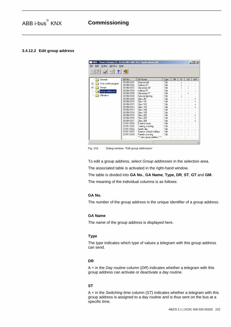
Commissioning
ABZ/S 2.1 | 2CDC 509 033 D0202 222
ABB i-bus KNX
3.4.12.2 Edit group address
Fig. 216: Dialog window: “Edit group addresses”
To edit a group address, select Group addresses in the selection area.
The associated table is activated in the right-hand window.
The table is divided into GA No., GA Name, Type, DR, ST, GT and GM.
The meaning of the individual columns is as follows:
GA No.
The number of the group address is the unique identifier of a group address.
GA Name
The name of the group address is displayed here.
Type
The type indicates which type of values a telegram with this group address can send.
DR
A + in the Day routine column (DR) indicates whether a telegram with this group address can activate or deactivate a day routine.
ST
A + in the Switching time column (ST) indicates whether a telegram with this group address is assigned to a day routine and is thus sent on the bus at a specific time.

Commissioning
ABZ/S 2.1 | 2CDC 509 033 D0202 223
ABB i-bus KNX
GT
A + in the Group trigger column (GT) indicates whether this group address can trigger a group.
GM
A + in the Group member column (GM) indicates whether this group address belongs to a group.
Note: The editing of group addresses is only possible in ETS3.

Commissioning
ABZ/S 2.1 | 2CDC 509 033 D0202 224
ABB i-bus KNX
Select an existing group address e.g. group address 00/00/001. The dialog window Link group address is activated in the following way:
- by double-clicking on the selected group address or - by pressing the right mouse button and selecting Edit in the pop-up menu.
Fig. 217: Parameter window: “Select group address””
Note: This dialog window can only be opened if the group address has already been assigned a specific use e.g. activating a day routine. The group address is thus assigned to a communication object via priority control.
Communication object: X
The communication object number is automatically assigned as a consecutive number by the application program Times Groups/2.
as switching time in Day routine no. 01
The text displayed here describes the assignment of the selected group address e.g. to the switching time and day routine.
Group address
Options: existing group address / new group address
An existing group address can be assigned in the selection list.
The parameter is divided into Type, Name and No. The table can be arranged and sorted as required.
The meaning of the individual columns is as follows:

Commissioning
ABZ/S 2.1 | 2CDC 509 033 D0202 225
ABB i-bus KNX
Type
The type indicates which type of values a telegram with this group address can send.
Name
The name of the group address is defined when configuring the ABB i-bus® installation and cannot be modified with the parameterisation software PZM2.
No.
The number of the group address is the unique identifier of a group address.
“OK” button
When the “OK” button is pressed, the settings are adopted and the parameter window closes.
“Cancel” button
When the “Cancel” button is pressed, the function is aborted and the parameter window closes.
“Help” button
The “Help” file can be opened directly via the “Help” button and a further parameter window Help for application program… is opened.

Commissioning
ABZ/S 2.1 | 2CDC 509 033 D0202 226
ABB i-bus KNX
After selecting the option new group address, the associated dialog window Add group addresses is activated.
Fig. 218: Dialog window: “Select group address”
The main group, middle group and the subgroup are created in sequence via drag & drop.
The Accept button is activated by clicking on the group address in the right-hand window.
The new group address is adopted in the following way:
- by double-clicking on the active group address or - by pressing the right mouse button and selecting Accept in the pop-up menu or - by pressing the Accept button.

Commissioning
ABZ/S 2.1 | 2CDC 509 033 D0202 227
ABB i-bus KNX
After pressing the Accept button, a further dialog window Group address becomes active. The data type for the newly created group address is selected in this window.
Fig. 219: Parameter window: “Group address, Select data type”
“OK” button
When the “OK” button is pressed, the settings are adopted and the parameter window closes.
“Cancel” button
When the “Cancel” button is pressed, the function is aborted and the parameter window closes.
“Help” button
The “Help” file can be opened directly via the “Help” button and a further parameter window Help for application program… is opened.
Note: The transfer of the newly created group address to ETS3 is only carried out after exiting the ABZ/S parameterisation and after confirming the prompt that the modified data should be saved. The editing of the group addresses such as modification of the description or deletion can only be carried out in ETS3.

Commissioning
ABZ/S 2.1 | 2CDC 509 033 D0202 228
ABB i-bus KNX
Note: Different data types appear in the table under Type, depending on which data type has been selected for a group address.
Fig. 220: Dialog window: “Group addresses with different data types”

Commissioning
ABZ/S 2.1 | 2CDC 509 033 D0202 229
ABB i-bus KNX
3.4.12.3 Delete group address
Fig. 221: Dialog window: “Delete group address”
Note: The deletion of group addresses is only possible in ETS3. The deletion process described here refers to the used and unused group addresses in the application program. If the group addresses in the dialog are deleted, they remain available.
To delete a group address, select Group addresses in the selection area.
The associated table is activated in the right-hand window.
The table is divided into GA No., GA Name, Type, DR, ST, GT and GM.
The meaning of the individual columns is as follows:
GA No.
The number of the group address is the unique identifier of a group address.
GA Name
The name of the group address is displayed here.
Type
The type indicates which type of values a telegram with this group address can send.
DR
A + in the Day routine column (DR) indicates whether a telegram with this group address can activate or deactivate a day routine.

Commissioning
ABZ/S 2.1 | 2CDC 509 033 D0202 230
ABB i-bus KNX
ST
A + in the Switching time column (ST) indicates whether a telegram with this group address is assigned to a day routine and is thus sent on the bus at a specific time.
GT
A + in the Group trigger column (GT) indicates whether this group address can trigger a group.
GM
A + in the Group member column (GM) indicates whether this group address belongs to a group.
Note: The deletion of group addresses is only possible in ETS3.
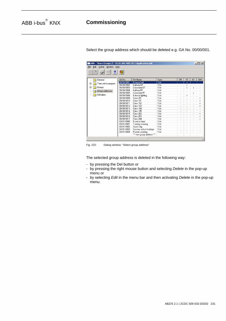
Commissioning
ABZ/S 2.1 | 2CDC 509 033 D0202 231
ABB i-bus KNX
Select the group address which should be deleted e.g. GA No. 00/00/001.
Fig. 222: Dialog window: “Select group address”
The selected group address is deleted in the following way:
- by pressing the Del button or - by pressing the right mouse button and selecting Delete in the pop-up menu or - by selecting Edit in the menu bar and then activating Delete in the pop-up menu.

Commissioning
ABZ/S 2.1 | 2CDC 509 033 D0202 232
ABB i-bus KNX
Before the group address can be deleted, a further dialog window Usage is opened. This window displays the use of the selected group address.
“Delete” button
The group address is deleted via this button and the parameter window closes.
Fig. 223: Dialog window” Usage”
“Cancel” button
When the “Cancel” button is pressed, the function is aborted and the parameter window closes.
“Help” button
The “Help” file can be opened directly via the “Help” button and a further parameter window Help for application program… is opened.
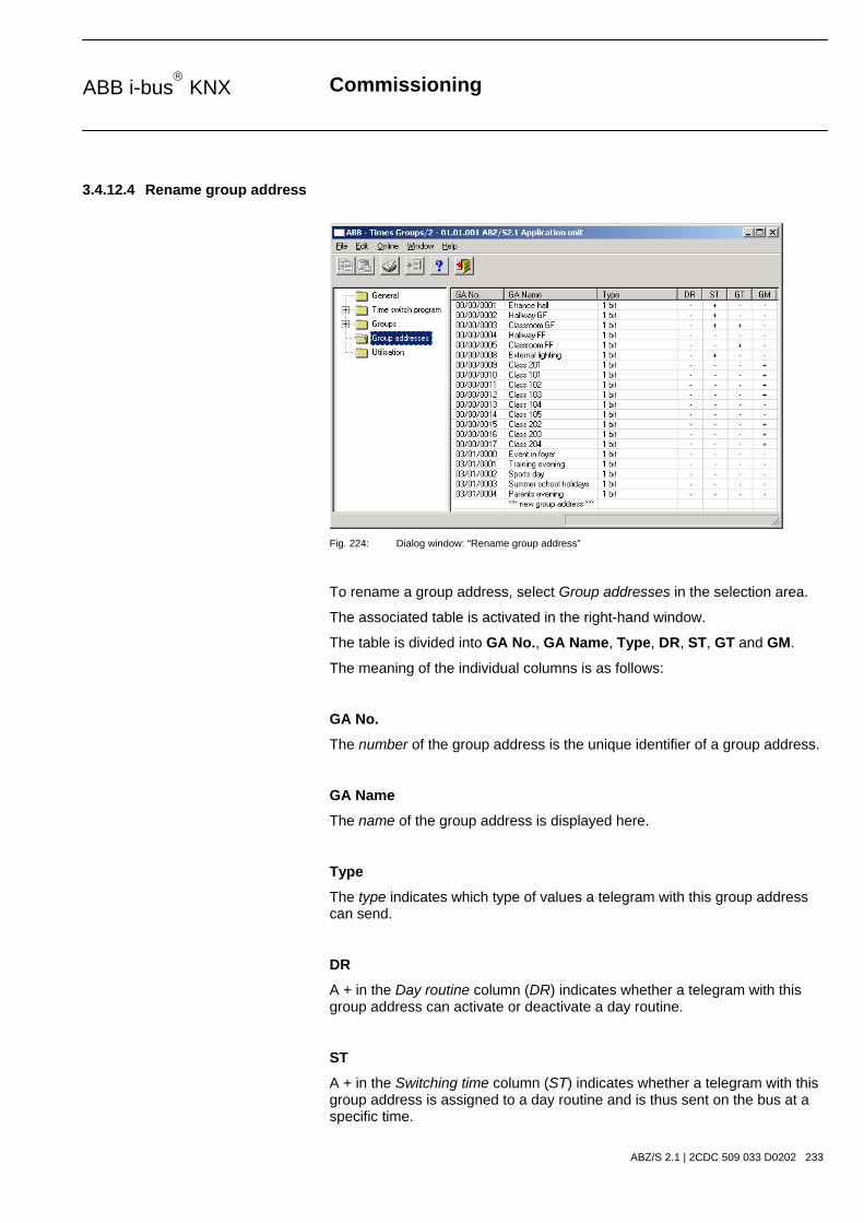
Commissioning
ABZ/S 2.1 | 2CDC 509 033 D0202 233
ABB i-bus KNX
3.4.12.4 Rename group address
Fig. 224: Dialog window: “Rename group address”
To rename a group address, select Group addresses in the selection area.
The associated table is activated in the right-hand window.
The table is divided into GA No., GA Name, Type, DR, ST, GT and GM.
The meaning of the individual columns is as follows:
GA No.
The number of the group address is the unique identifier of a group address.
GA Name
The name of the group address is displayed here.
Type
The type indicates which type of values a telegram with this group address can send.
DR
A + in the Day routine column (DR) indicates whether a telegram with this group address can activate or deactivate a day routine.
ST
A + in the Switching time column (ST) indicates whether a telegram with this group address is assigned to a day routine and is thus sent on the bus at a specific time.
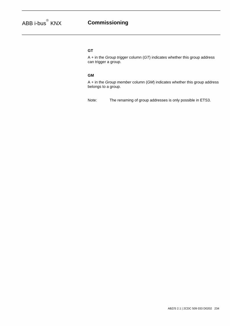
Commissioning
ABZ/S 2.1 | 2CDC 509 033 D0202 234
ABB i-bus KNX
GT
A + in the Group trigger column (GT) indicates whether this group address can trigger a group.
GM
A + in the Group member column (GM) indicates whether this group address belongs to a group.
Note: The renaming of group addresses is only possible in ETS3.

Commissioning
ABZ/S 2.1 | 2CDC 509 033 D0202 235
ABB i-bus KNX
3.4.12.5 Assign group address
Fig. 225: Dialog window: “Assign group address”
To assign a group address, select Group addresses in the selection area.
The associated table is activated in the right-hand window.
The table is divided into GA No., GA Name, Type, DR, ST, GT and GM.
The meaning of the individual columns is as follows:
GA No.
The number of the group address is the unique identifier of a group address.
GA Name
The name of the group address is displayed here.
Type
The type indicates which type of values a telegram with this group address can send.
DR
A + in the Day routine column (DR) indicates whether a telegram with this group address can activate or deactivate a day routine.
ST
A + in the Switching time column (ST) indicates whether a telegram with this group address is assigned to a day routine and is thus sent on the bus at a specific time.

Commissioning
ABZ/S 2.1 | 2CDC 509 033 D0202 236
ABB i-bus KNX
GT
A + in the Group trigger column (GT) indicates whether this group address can trigger a group.
GM
A + in the Group member column (GM) indicates whether this group address belongs to a group.
Note: The assignment of group addresses is only possible in ETS3.

Commissioning
ABZ/S 2.1 | 2CDC 509 033 D0202 237
ABB i-bus KNX
Select an existing group address e.g. the group address 00/00/001. The dialog window Link group address is activated in the following way:
- by double-clicking on the selected group address or - by pressing the right mouse button and selecting Edit in the pop-up menu.
Fig. 226: Parameter window: “Assign group address”
Note: This dialog window can only be opened if the group address has already been assigned a specific use e.g. activating a day routine. The group address is thus assigned to a communication object via priority control.
Communication object: X
The communication object number is automatically assigned as a consecutive number by the application program Times Groups/2.
as switching time in Day routine no. 01
The text displayed here describes the assignment of the selected group address e.g. to the switching time and day routine.
Note: A group address can be reassigned for the communication object number and the description. If a new assignment is selected, this is represented in the table in the column DR, ST, GT or GM with a +.

Commissioning
ABZ/S 2.1 | 2CDC 509 033 D0202 238
ABB i-bus KNX
Group address
Options: existing group address / new group address
An existing group address can be assigned in the selection list.
The parameter is divided into Type, Name and No. The table can be arranged and sorted as required.
The meaning of the individual columns is as follows:
Type
The type indicates which type of values a telegram with this group address can send.
Name
The name of the group address is defined when configuring the ABB i-bus® installation and cannot be modified with the parameterisation software PZM2.
No.
The number of the group address is the unique identifier of a group address.
“OK” button
When the “OK” button is pressed, the settings are adopted and the parameter window closes.
“Cancel” button
When the “Cancel” button is pressed, the function is aborted and the parameter window closes.
“Help” button
The “Help” file can be opened directly via the “Help” button and a further parameter window Help for application program… is opened.

Commissioning
ABZ/S 2.1 | 2CDC 509 033 D0202 239
ABB i-bus KNX
After selecting the option new group address, the associated dialog window Add group addresses is activated.
Fig. 227: Dialog window: “Select group address”
The main group, middle group and the subgroup are created in sequence via drag & drop.
The Accept button is activated by clicking on the group address in the right-hand window.
The new group address is adopted in the following way:
- by double-clicking on the active group address or - by pressing the right mouse button and selecting Accept in the pop-up menu or - by pressing the Accept button.

Commissioning
ABZ/S 2.1 | 2CDC 509 033 D0202 240
ABB i-bus KNX
After pressing the Accept button, a further dialog window Group address becomes active. The data type for the newly created group address is selected in this window.
Fig. 228: Parameter window: “Group address, Select data type”
“OK” button
When the “OK” button is pressed, the settings are adopted and the parameter window closes.
“Cancel” button
When the “Cancel” button is pressed, the function is aborted and the parameter window closes.
“Help” button
The “Help” file can be opened directly via the “Help” button and a further parameter window Help for application program… is opened.
Note: The transfer of the newly created group address to ETS3 is only carried out after exiting the ABZ/S parameterisation and after confirming the prompt that the modified data should be saved. The editing of the group addresses such as modification of the description or deletion can only be carried out in ETS3.
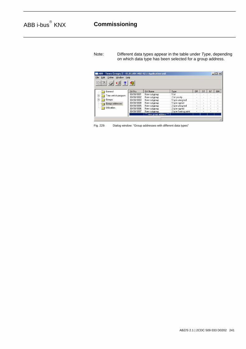
Commissioning
ABZ/S 2.1 | 2CDC 509 033 D0202 241
ABB i-bus KNX
Note: Different data types appear in the table under Type, depending on which data type has been selected for a group address.
Fig. 229: Dialog window: “Group addresses with different data types”

Commissioning
ABZ/S 2.1 | 2CDC 509 033 D0202 242
ABB i-bus KNX
3.4.13 Utilisation
Fig. 230: Dialog window: “Utilisation”
Select Utilisation in the selection area.
The associated table is activated in the right-hand window.
The table is divided into Field name, Size, used, (%) and free.
The meaning of the individual columns is as follows:
Field name
Under Field name, you find a selection of addresses and objects with subdivision into group addresses, objects and associations. Under time switch program, there is a further division into day routines, switching times, special days and daylight saving times. The groups are subdivided into groups and group members.
Size
The maximum possible number is displayed here.
used
The current number is displayed here.
(%)
The number used is shown here as a percentage.
free
The number still available is shown here.

Commissioning
ABZ/S 2.1 | 2CDC 509 033 D0202 243
ABB i-bus KNX
3.5 Communication objects 250 to 253
Fig. 231: Communication objects 250 to 253
No. Function Object name Data type Flags
250 Request object EIS 1, 1 bit
DTP 1.001
C, R, W, T
The date and time can be queried via this communication object.
Telegram value “0” do not start a query “1” start query
This communication object is only visible if the options Slave or Master have been selected in the parameter Operating mode of clock.
251 Date EIS4, 3 byte
DTP 10.001
C, R, W, T
This communication object is used to send or receive the date.
252 Time EIS3, 3 byte
DTP 11.001
C, R, W, T
This communication object is used to send or receive the time.
253 Time program lock / unlock
EIS1, 1 bit
DTP 1.001
C, R, W, T
The communication object has the following meaning depending on the options in the Time switch program parameter – unlock with 1 or lock with 1:
lock with 1, telegram value “0” unlock “1” lock
unlock with 1, telegram value “0” lock “1” unlock
This communication object is always active as it can also be assigned a group address directly by ETS3.
Table 16: Communication objects 250 to 253 “General”

Planning and application
ABZ/S 2.1 | 2CDC 509 033 D0202 244
ABB i-bus KNX
4 Planning and application
This section contains some practical tips for using the Application Unit Time.
4.1 Context-sensitive “Help” file
The context-sensitive “Help” file gives you the necessary information for each step when parameterising the application program Times Groups/2.
The context-sensitive “Help” file is retrieved in the following way:
- press the Help button in the dialog window,
- press the right mouse button in the table area to select Help,
- press F1 on the keyboard or
- press the Help button on the toolbar.
The best way of working with the application program and the “Help” file is to proceed as follows:
First start ETS3 and open the project which you wish to edit. Minimise the main ETS3 window and move it to the top right-hand corner.
After starting the application program, minimise the window and move it to the right edge of the screen so that about a third of the screen width remains free. Now retrieve the “Help” file and minimise and position the window in the free area on the left-hand edge of the screen.
You can now see the relevant “Help” page for each step on the left-hand side if you retrieve the context-sensitive “Help” file to obtain information. You can receive further explanations about the green, underlined terms by clicking on them. You return to the previous “Help” page via the “Back” button.

Planning and application
ABZ/S 2.1 | 2CDC 509 033 D0202 245
ABB i-bus KNX
4.2 Behaviour on bus voltage failure
In the event of a bus voltage failure, the Application Unit Time stores the communication object values of the inputs and outputs for at least 1 h. If the bus voltage failure lasts considerably longer, the stored communication object values are lost.
Secure states after a bus voltage failure can be achieved by selecting the parameter setting “Behaviour after bus voltage recovery”.
4.3 Behaviour after bus voltage recovery
To prevent an unwanted operational response after a bus voltage failure, particular in larger installations, the installation of an uninterruptible power supply is provided for the bus voltage and the scanning voltage of the contacts.

Appendix
ABZ/S 2.1 | 2CDC 509 033 D0202 VII
ABB i-bus KNX
Appendix
A.1 Scope of supply
The Application Unit Time is supplied with the following parts. Please check the scope of supply according to the following list.
- 1 x ABZ/S 2.1, Application Unit Time, MDRC
- 1 x installation and operating instructions
- 1 x bus connecting terminal (red/black)

Appendix
ABZ/S 2.1 | 2CDC 509 033 D0202 VIII
ABB i-bus KNX
A.2 List of diagrams
Fig. 1: ABZ/S 2.1 .........................................................................................................................8 Fig. 2: Circuit diagram .................................................................................................................9 Fig. 3: Dimension drawing .........................................................................................................10 Fig. 4: ETS3 “General” dialog window.......................................................................................14 Fig. 5: “Times Groups/2” screen................................................................................................15 Fig. 6: “Title bar” screen ............................................................................................................15 Fig. 7: “Menu bar” screen ..........................................................................................................15 Fig. 8: “Status bar” screen .........................................................................................................15 Fig. 9: “File” menu .....................................................................................................................16 Fig. 10: “Export” screen ...............................................................................................................17 Fig. 11: “Import” screen ...............................................................................................................18 Fig. 12: “Page view” screen.........................................................................................................19 Fig. 13: “Filter print data” screen .................................................................................................20 Fig. 14: “Edit” menu .....................................................................................................................22 Fig. 15: “Online” menu.................................................................................................................23 Fig. 16: Parameter window: “Online menu, Set date/time”..........................................................24 Fig. 17: Parameter window: ”Online menu, Show status” ...........................................................26 Fig. 18: “Window” menu ..............................................................................................................27 Fig. 19: “Help” menu....................................................................................................................28 Fig. 20: “About…” ........................................................................................................................28 Fig. 21: “Toolbar” screen .............................................................................................................29 Fig. 22: “Copy” symbol ................................................................................................................29 Fig. 23: “Paste” symbol................................................................................................................29 Fig. 24: “Print” symbol .................................................................................................................29 Fig. 25: “Save” symbol.................................................................................................................30 Fig. 26: “Help” symbol .................................................................................................................30 Fig. 27: “Close” symbol................................................................................................................30 Fig. 28: Parameter window: “General”.........................................................................................31 Fig. 29: Dialog window: “Time program, Add group addresses” .................................................33 Fig. 30: Parameter window: “Time program, Create new main group, middle group and
subgroup” .......................................................................................................................33 Fig. 31: Dialog window: “Time program, Main group, middle group and subgroup created”.......34 Fig. 32: Dialog window: “Time program, Middle group marked”..................................................34 Fig. 33: Dialog window: “Time program, Subgroup marked” .......................................................34 Fig. 34: Parameter window: “General, Lock time program”.........................................................35 Fig. 35: Parameter window: “General, Operating mode of clock” ...............................................36 Fig. 36: Parameter window: “General, Operating mode of clock, Slave (always receive)” .........38 Fig. 37: Dialog window: “Operating mode of clock, Add group addresses”.................................39 Fig. 38: Parameter window: “Operating mode of clock, Create new main group, middle group and subgroup” ................................................................................................................39 Fig. 39: Dialog window: “Operating mode of clock, Main group, middle group and subgroup created” ..........................................................................................................................40 Fig. 40: Dialog window: “Operating mode of clock, Middle group marked” .................................40 Fig. 41: Dialog window: “Operating mode of clock, Subgroup marked” ......................................40 Fig. 42: Parameter window: “General, Operating mode of clock, Master (send hourly)” ............42 Fig. 43: Parameter window: “General, Operating mode of clock, Master (send daily)” ...............43 Fig. 44: “Time switch program” screen ........................................................................................44 Fig. 45: Dialog window: “Day routines - General”........................................................................45 Fig. 46: Dialog window: “Insert day routines” ..............................................................................46 Fig. 47: Parameter window: “Insert new day routine” ..................................................................47 Fig. 48: Parameter window: “Day routine, Select new group address” .......................................48 Fig. 49: Dialog window: “Day routine, Add group addresses” .....................................................49 Fig. 50: Parameter window: “Day routine, Create new main group, middle group and
subgroup” .......................................................................................................................49 Fig. 51: Dialog window: “Day routine, Main group, middle group and subgroup created”...........50 Fig. 52: Dialog window: “Day routine, Middle group marked”......................................................50 Fig. 53: Dialog window: “Day routine, Subgroup marked” ...........................................................50 Fig. 54: Parameter window: “Day routine, Group address inserted” ...........................................51 Fig. 55: Dialog window: “Day routine, Group address displayed” ...............................................51 Fig. 56: Dialog window: “Edit day routines” .................................................................................52 Fig. 57: Parameter window: “Select day routine” ........................................................................53 Fig. 58: Parameter window: “Day routine, Select new group address” .......................................54 Fig. 59: Dialog window: “Day routine, Select group address” .....................................................55 Fig. 60: Dialog window: “Delete day routines” .............................................................................56 Fig. 61: Dialog window: “Select day routine” ...............................................................................57 Fig. 62: Parameter window: “Day routine, Prompt” .....................................................................57 Fig. 63: Dialog window: “Switching time - General”.....................................................................58 Fig. 64: Dialog window: “Insert switching time” ...........................................................................59 Fig. 65: Parameter window: “Insert new switching time” .............................................................61 Fig. 66: Parameter window: “Switching time, Select new group address” ..................................62

Appendix
ABZ/S 2.1 | 2CDC 509 033 D0202 IX
ABB i-bus KNX
Fig. 67: Dialog window: “Switching time, Add group addresses” ................................................63 Fig. 68: Parameter window: “Switching time, Create new main group, middle group and
subgroup” .......................................................................................................................63 Fig. 69: Parameter window: “Switching time, Main group, middle group and subgroup ...............
created” ..........................................................................................................................64 Fig. 70: Dialog window: “Switching time, Middle group marked”.................................................64 Fig. 71: Dialog window: “Switching time, Subgroup marked” ......................................................64 Fig. 72: Parameter window: “Switching time, Select data type” ..................................................65 Fig. 73: Parameter window: “Switching time, Data type 1 bit” .....................................................66 Fig. 74: Parameter window: “Switching time, Data type 2 bit priority” .........................................67 Fig. 75: Parameter window: “Switching time, Data type 1 byte unsigned (0…255)” ...................68 Fig. 76: Parameter window: “Switching time, Data type 1 byte unsigned (0…100%)” ................68 Fig. 77: Parameter window: “Switching time, Data type 1 byte signed (-128…127)” ..................69 Fig. 78: Parameter window: “Switching time, Data type 2 byte unsigned (0…65,535)” ..............69 Fig. 79: Parameter window: “Switching time, Data type 2 byte signed (-32,768…32,767)” ........70 Fig. 80: Parameter window: “Switching time, Data type 2 byte floating point” ............................70 Fig. 81: Dialog window: “Edit swtching time” ...............................................................................73 Fig. 82: Parameter window: “Select switching time”....................................................................75 Fig. 83: Parameter window: “Switching time for day routine - Normal weekday, Select group
address”..........................................................................................................................76 Fig. 84: Dialog window: “Switching time, Select group address”.................................................77 Fig. 85: Parameter window: “Switching time, Select data type” ..................................................78 Fig. 86: Parameter window: “Switching time, Data type 1 bit” .....................................................79 Fig. 87: Parameter window: “Switching time, Data type 2 bit priority” .........................................80 Fig. 88: Parameter window: “Switching time, Data type 1 byte unsigned (0…255)” ...................81 Fig. 89: Parameter window: “Switching time, Data type 1 byte unsigned (0…100%)” ................81 Fig. 90: Parameter window: “Switching time, Data type 1 byte signed (-128…127)” ..................82 Fig. 91: Parameter window: “Switching time, Data type 2 byte unsigned (0…65,535)” ..............82 Fig. 92: Parameter window: “Switching time, Data type 2 byte signed (-32,768…32,767)” ........83 Fig. 93: Parameter window: “Switching time, Data type 2 byte floating point” ............................83 Fig. 94: Dialog window: “Delete switching time” ..........................................................................86 Fig. 95: Dialog window: “Select switching time” ..........................................................................88 Fig. 96: Parameter window: “Switching time, Prompt”.................................................................88 Fig. 97: Parameter window: “Copy/insert switching time” ...........................................................89 Fig. 98: Dialog window: “Select switching time” ..........................................................................91 Fig. 99: Parameter window: “Set switching time” ........................................................................92 Fig. 100: Dialog window: “Week routine - General”.......................................................................93 Fig. 101: Dialog window: “Insert week routine”..............................................................................94 Fig. 102: Parameter window: “Standard day routine for Monday, Insert day routine” ...................95 Fig. 103: Dialog window: “Edit week routine” ................................................................................96 Fig. 104: Parameter window: “Standard day routine for Sunday, Insert day routine”....................97 Fig. 105: Dialog window: “Delete week routine” ............................................................................98 Fig. 106: Dialog window: “Select week routine”.............................................................................99 Fig. 107: Dialog window: “Daylight saving time - General”..........................................................100 Fig. 108: Dialog window: “Insert new daylight saving time”.........................................................101 Fig. 109: Parameter window: “Insert daylight saving time”..........................................................102 Fig. 110: Dialog window: “Option to automatically calculate daylight saving time activated” ......103 Fig. 111: Dialog window: “Option to automatically calculate daylight saving time not ...................
activated” ......................................................................................................................103 Fig. 112: Dialog window: “Edit daylight saving time” ...................................................................105 Fig. 113: Parameter window: “Select daylight saving time”.........................................................106 Fig. 114: Dialog window: “Delete daylight saving time”...............................................................107 Fig. 115: Dialog window: “Select daylight saving time” ...............................................................108 Fig. 116: Parameter window: “Daylight saving time, Prompt” .....................................................108 Fig. 117: Dialog window: “Special days - General”......................................................................109 Fig. 118: Dialog window: “Insert new special day” ......................................................................110 Fig. 119: Parameter window: “Set special day range”.................................................................111 Fig. 120: Parameter window: “Special day range, Select day routine”........................................112 Fig. 121: Dialog window: “Edit special day”.................................................................................113 Fig. 122: Parameter window: “Modify special day range” ...........................................................114 Fig. 123: Dialog window: “Delete special day”.............................................................................115 Fig. 124: Dialog window: “Select special day” .............................................................................116 Fig. 125: Parameter window: “Special day, Prompt” ...................................................................116 Fig. 126: Parameter window: “Special days, Overlapping of periods”.........................................117 Fig. 127: Dialog window: “Overview - General” ...........................................................................118 Fig. 128: Dialog window: “Display overview” ...............................................................................119 Fig. 129: Dialog window: “Groups - General” ..............................................................................122 Fig. 130: Dialog window: “Insert new group” ...............................................................................123 Fig. 131: Parameter window: “Group” .........................................................................................124 Fig. 132: Parameter window: “Group, Data type 1 bit” ................................................................127 Fig. 133: Parameter window: “Group, Data type 1 byte unsigned (0…255)” ..............................128 Fig. 134: Parameter window: “Group, Data type 1 byte unsigned (0…100%)” ...........................129 Fig. 135: Parameter window: “Group, Data type 1 byte signed (-128…127)” .............................130 Fig. 136: Parameter window: “Group, Data type 2 byte unsigned (0…65,535)” .........................131

Appendix
ABZ/S 2.1 | 2CDC 509 033 D0202 X
ABB i-bus KNX
Fig. 137: Parameter window: “Group, Data type 2 byte signed (-32,768…32,767)” ...................132 Fig. 138: Parameter window: “Group, Data type 2 byte floating point”........................................133 Fig. 139: Example: Hysteresis, Group activated/deactivated......................................................136 Fig. 140: Dialog window: “Edit group”..........................................................................................140 Fig. 141: Parameter window: “Select group” ...............................................................................141 Fig. 142: Parameter window: “Group, Data type 1 bit” ................................................................144 Fig. 143: Parameter window: “Group, Data type 1 byte unsigned (0…255)” ..............................145 Fig. 144: Parameter window: “Group, Data type 1 byte unsigned (0…100%)” ...........................146 Fig. 145: Parameter window: “Group, Data type 1 byte signed (-128…127)” .............................147 Fig. 146: Parameter window: “Group, Data type 2 byte unsigned (0…65,535)” .........................148 Fig. 147: Parameter window: “Group, Data type 2 byte signed (-32,768…32,767)” ...................149 Fig. 148: Parameter window: “Group, Data type 2 byte floating point”........................................150 Fig. 149: Example: Hysteresis, Group activated/deactivated......................................................153 Fig. 150: Dialog window: “Modify group” .....................................................................................157 Fig. 151: Parameter window: “Select group” ...............................................................................158 Fig. 152: Parameter window: “Group, Data type 1 bit” ................................................................161 Fig. 153: Parameter window: “Group, Data type 1 byte unsigned (0…255)” ..............................162 Fig. 154: Parameter window: “Group, Data type 1 byte unsigned (0…100%)” ...........................163 Fig. 155: Parameter window: “Group, Data type 1 byte signed (-128…127)” .............................164 Fig. 156: Parameter window: “Group, Data type 2 byte unsigned (0…65,535)” .........................165 Fig. 157: Parameter window: “Group, Data type 2 byte signed (-32,768…32,767)” ...................166 Fig. 158: Parameter window: “Group, Data type 2 byte floating point”........................................167 Fig. 159: Example: Hysteresis, Group activated/deactivated......................................................170 Fig. 160: Dialog window: “Group trigger - General”.....................................................................174 Fig. 161: Dialog window: “Insert new group trigger” ....................................................................175 Fig. 162: Parameter window: “Trigger for group 01: Beginning of instruction, Insert group
address”........................................................................................................................176 Fig. 163: Dialog window: “Group trigger, Add group addresses” ................................................177 Fig. 164: Parameter window: “Group trigger, Create new main group, middle group and
subgroup” .....................................................................................................................177 Fig. 165: Dialog window: “Group trigger, Main group, middle group and subgroup created”......178 Fig. 166: Dialog window: “Group trigger, Middle group marked” .................................................178 Fig. 167: Dialog window: “Group trigger, Subgroup marked” ......................................................178 Fig. 168: Parameter window: “Group trigger, Group address inserted” ......................................179 Fig. 169: Dialog window: “Edit group trigger” ..............................................................................180 Fig. 170: Parameter window: “Edit group trigger”........................................................................181 Fig. 171: Dialog window: “Group trigger, Select group address”.................................................182 Fig. 172: Dialog window: “Delete group trigger” ..........................................................................184 Fig. 173: Dialog window: “Select group trigger”...........................................................................185 Fig. 174: Parameter window: “Group trigger, Prompt”.................................................................185 Fig. 175: Dialog window: “Group members - General” ................................................................186 Fig. 176: Dialog window: “Insert new group member” .................................................................187 Fig. 177: Parameter window: “Insert member for group 01”........................................................189 Fig. 178: Dialog window: “Group member, Add group addresses” .............................................190 Fig. 179: Parameter window: “Group member, Create new main group, middle group and
subgroup” .....................................................................................................................190 Fig. 180: Dialog window: “Group member, Main group, middle group and subgroup”................191 Fig. 181: Dialog window: “Group member, Middle group marked”..............................................191 Fig. 182: Dialog window: “Group member, Subgroup marked” ...................................................191 Fig. 183: Parameter window: “Group member, Select data type” ...............................................192 Fig. 184: Parameter window: “Group member, Data type 1 bit” ..................................................193 Fig. 185: Parameter window: “Group member, Data type 2 bit priority” ......................................194 Fig. 186: Parameter window: “Group member, Data type 1 byte unsigned (0…255)” ................195 Fig. 187: Parameter window: “Group member, Data type 1 byte unsigned (0…100%)” .............195 Fig. 188: Parameter window: “Group member, Data type 1 byte signed (-128…127)” ...............196 Fig. 189: Parameter window: “Group member, Data type 2 Byte unsigned (0…65,535)”...........196 Fig. 190: Parameter window: “Group member, Data type 2 Byte signed (-32,768…32,767)”.....197 Fig. 191: Parameter window: “Group member, Data type 2 byte floating point” .........................197 Fig. 192: Dialog window: “Edit group member” ...........................................................................200 Fig. 193: Parameter window: “Select member for group 01”.......................................................202 Fig. 194: Dialog window: “Group member, Select group address”..............................................203 Fig. 195: Parameter window: “Group member, Select data type” ...............................................204 Fig. 196: Parameter window: “Group member, Data type 1 bit” ..................................................205 Fig. 197: Parameter window: “Group member, Data type 2 bit priority” ......................................206 Fig. 198: Parameter window: “Group member, Data type 1 byte unsigned (0…255)” ................207 Fig. 199: Parameter window: “Group member, Data type 1 byte unsigned (0…100%)” .............207 Fig. 200: Parameter window: “Group member, Data type 1 byte signed (-128…127)” ...............208 Fig. 201: Parameter window: “Group member, Data type 2 byte unsigned (0…65,535)” ...........208 Fig. 202: Parameter window: “Group member, Data type 2 Byte signed (-32,768…32,767)”.....209 Fig. 203: Parameter window: “Group member, Data type 2 byte floating point” .........................209 Fig. 204: Dialog window: “Delete group member” .......................................................................212 Fig. 205: Dialog window: “Select group member”........................................................................214 Fig. 206: Parameter window: “Group member, Prompt” .............................................................214 Fig. 207: Dialog window: “Group addresses - General” ..............................................................215

Appendix
ABZ/S 2.1 | 2CDC 509 033 D0202 XI
ABB i-bus KNX
Fig. 208: Dialog window: “Insert new group address” .................................................................216 Fig. 209: Dialog window: “Group address, Add group addresses”..............................................218 Fig. 210: Parameter window: “Group address, Create new main group, middle group and
subgroup” .....................................................................................................................218 Fig. 211: Dialog window: “Group address, Main group, middle group and subgroup created” ...219 Fig. 212: Dialog window: “Group address, Middle group marked” ..............................................219 Fig. 213: Dialog window: “Group address, Subgroup marked” ...................................................219 Fig. 214: Parameter window: “Group address, Select data type”................................................220 Fig. 215: Dialog window: “Group addresses with different data types” .......................................221 Fig. 216: Dialog window: “Edit group addresses”........................................................................222 Fig. 217: Parameter window: “Select group address” .................................................................224 Fig. 218: Dialog window: “Select group address” ........................................................................226 Fig. 219: Parameter window: “Group address, Select data type”................................................227 Fig. 220: Dialog window: “Group addresses with different data types” .......................................228 Fig. 221: Dialog window: “Delete group address”........................................................................229 Fig. 222: Dialog window: “Select group address” ........................................................................231 Fig. 223: Dialog window: “Usage”................................................................................................232 Fig. 224: Dialog window: “Rename group address” ....................................................................233 Fig. 225: Dialog window: “Assign group addresses” ...................................................................235 Fig. 226: Parameter window: “Assign group address” ................................................................237 Fig. 227: Dialog window: “Select group address” ........................................................................239 Fig. 228: Parameter window: “Group address, Select data type”................................................240 Fig. 229: Dialog window: “Group addresses with different data types” .......................................241 Fig. 230: Dialog window: “Utilisation” ..........................................................................................242 Fig. 231: Communication objects 250 to 253 ..............................................................................243

Appendix
ABZ/S 2.1 | 2CDC 509 033 D0202 XII
ABB i-bus KNX
A.3 List of tables
Table 1: Technical data ..................................................................................................................8 Table 2: Application program..........................................................................................................9 Table 3: Functions of the application program .............................................................................12 Table 4: Priority object..................................................................................................................67 Table 5: Exponent ........................................................................................................................71 Table 6: Priority object..................................................................................................................80 Table 7: Exponent ........................................................................................................................84 Table 8: Example of overlapping of periods ...............................................................................117 Table 9: Exponent ......................................................................................................................134 Table 10: Exponent ......................................................................................................................151 Table 11: Exponent ......................................................................................................................168 Table 12: Priority object................................................................................................................194 Table 13: Exponent ......................................................................................................................198 Table 14: Priority object................................................................................................................206 Table 15: Exponent ......................................................................................................................210 Table 16: Communication objects 250 to 253 “General” ..............................................................243 Table 17: Ordering information for Application Unit Time, MDRC................................................XIV

Appendix
ABZ/S 2.1 | 2CDC 509 033 D0202 XIII
ABB i-bus KNX
A.4 List of key words
Auslieferungszustand 11 Auswahlbereich 86, 89, 94, 96, 98, 101, 105, 110,
113, 115, 119, 123, 140, 157, 175, 180, 184, 187, 200, 212, 216, 222, 229, 233, 235
Auswahlmenü Fenster 15, 27, 29 Auswahlmenü Hilfe 28 Auswahlmenü Online 23 Beenden 21 Busspannung 8, 10 Datum/Uhrzeit einstellen 24 Druckdaten filtern 20 Drucken 18, 29 Drucker einrichten 21 Exportieren 17 Gerätestatus anzeigen 26 Hilfe 15, 28, 30, 244 Importieren 18 Inaktive Zeit 31 Inbetriebnahmevoraussetzung 10 Jahresschaltprogramm 8 Kaltstart 123, 137, 138, 139, 140, 154, 155, 156,
171, 172, 173 Master 36, 38, 41, 42, 43, 243 Menge 12, 122, 123, 124, 125, 126, 135, 136, 137,
138, 140, 141, 142, 143, 152, 153, 154, 155, 157, 158, 159, 160, 169, 170, 171, 172, 174, 175, 179, 180, 183, 184, 186, 188, 201, 213, 217, 223, 230, 234, 236
Mengen 7, 122, 124, 141, 158, 175, 180, 184, 187, 200, 212, 224, 237, 242, 244
Mengenauslöser 12, 122, 125, 142, 159, 174, 181, 217, 223, 230, 234, 236
Mengenmitglieder 12, 22, 122, 242 Programmierung 12 PZM 2.0 14 PZM2 36, 48, 54, 62, 76, 120, 176, 181, 189, 202,
225, 238 Reinigen 11 Schaltzeiten 12, 44, 59 Seitenansicht 19 Slave 36, 38, 41, 243 Sommerzeit 12, 104 Sommerzeiten 242 Sondertage 7, 12, 109, 113, 117 Speichern 16, 21, 30 Statusleiste 15, 27 Stromaufnahme, Bus 8 Symbolleiste 27, 29 Tabellenbereich 14, 244 Tagesablauf 7, 8, 22, 26, 27, 44, 45, 46, 47, 48, 52,
53, 54, 56, 57, 59, 95, 96, 97, 98, 109, 110, 112, 113, 115, 121, 216, 222, 229, 230, 233, 235
Tagesabläufe 12, 44, 45, 46, 52, 56, 59, 73, 86, 89, 94, 96, 98
Telegrammabstand 31 Vergabe der physikalischen Adresse 7, 8, 11 Verlustleistung, Bus 8 Versorgung 8 Warmstart 123, 138, 140, 155, 172 Wartung 11 Wochenablauf 7, 8, 12, 44, 93, 94, 96, 98, 99, 109 Zeitschaltprogramm 12, 17, 25, 36, 44, 45, 46, 52,
56, 59, 73, 86, 89, 94, 96, 98, 101, 105, 107, 110, 113, 115, 119, 122, 137, 154, 171

Appendix
ABZ/S 2.1 | 2CDC 509 033 D0202 XIV
ABB i-bus KNX
A.5 Ordering information
Short code Description Order no. bbn 40 16779EAN
Price group
Unit weight [kg]
Pack unit [pce.]
ABZ/S 2.1 Application Unit Time, MDRC 2CDG 110 072 R0011 652 36 0 26 0.1 1
Table 17: Ordering information for Application Unit Time, MDRC

Appendix
ABZ/S 2.1 | 2CDC 509 033 D0202 XV
ABB i-bus KNX
A.6 Notes

Appendix
ABZ/S 2.1 | 2CDC 509 033 D0202 XVI
ABB i-bus KNX


Pub
licat
ion
Num
ber
2CD
C 5
09 0
33
D02
02
(03.
11)ABB STOTZ-KONTAKT GmbH
Eppelheimer Straße 82 69123 Heidelberg, Germany Phone: +49 (0)6221 701 607 Fax: +49 (0)6221 701 724 E-mail: [email protected] Further information and contacts: www.abb.com/knx
Note:We reserve the right to make technical changes to the products as well as amendments to the content of this document at any time without advance notice. The agreed properties are definitive for any orders placed. ABB AG shall not be liable for any consequences arising from errors or incomplete information in this document. We reserve the rights to this document and all the items and illustrations contained therein.
Reproduction, transfer to third parties or processing
of the content – including sections thereof – is not permitted without prior expressed written permission from ABB AG. Copyright© 2011 ABB All rights reserved
Contact