ABB general machinery drives
14
PROFILE INDUSTRIES APPLICATIONS EXPERTISE PARTNERS PRODUCTS SERVICES ABB general machinery drives ACS350, 0.37 to 11 kW / 0.5 to 15 hp Technical catalogue
Transcript of ABB general machinery drives

PROFILE INDUSTRIES
APPLICATIONS EXPERTISE
PARTNERS
PRODUCTS
SERVICES
ABB general machinery drivesACS350, 0.37 to 11 kW / 0.5 to 15 hp
Technical catalogue

3AFE68596106 REV D EN 22.11.20062 ABB
Choice 1: Simply contact your local ABB drives
sales offi ce (see page 15) and let them know what
you want. Use page 3 as a reference section for
more information.
Two ways to select your drive
Choice 2: Build up your own ordering code using
the simple 7-step approach below. Each step is
accompanied by a reference to a page that is fi lled
with useful information.
OR
Type code stucture:
Product series
Rating and types
Voltages
Construction
Dimension
Options
Technical data
Control connections
Services
Contact and web information
1
2
34
5
6
7
89
ACS350 - 01E - 02A4 - 2 + J400

3AFE68596106 REV D EN 22.11.2006 3ABB
1
2
34
5
6
7
89
Contents
ABB general machinery drives, ACS350
ABB general machinery drives ........................................4
Features .............................................................4
Technical specifi cation ....................................................5
Electromagnetic compatibility .........................................6
Ratings, types, voltages and construction ......................6
Type code ..........................................................6
Voltages .............................................................6
Construction .......................................................6
Phase and EMC fi ltering ......................................6
Dimensions .....................................................................7
Cabinet-mounted drives ....................................7
Wall-mounted drives ..........................................7
Options ..........................................................................7
How to select options ........................................7
User interfaces ...................................................8
Machine interfaces .............................................9
Protection and installation ..................................9
FlashDrop ........................................................10
Brake resistors .................................................10
Input and output chokes ..................................10
DriveWindow Light 2 ........................................11
Technical data .............................................................12
Cooling and fuses ............................................12
Control connections ....................................................13
Connection examples ......................................13
Services .......................................................................14
www.abb.com/motors&drives ......................................15

3AFE68596106 REV D EN 22.11.20064 ABB
ABB general machinery drives
ABB general machinery drives
ABB general machinery drives are designed for
machine building. In serial type manufacturing
the consumed time per unit is critical. The drives
are designed to be the fastest drives in terms of
installation, setting parameters and com mis sion ing.
The basic products have been made as user-friendly
as possible, yet providing high in tel li gence. The
drives offer diverse functionality to cater for the most
de mand ing needs.
Applications
ABB general machinery drives are designed to meet
the requirements of an extensive range of machinery
ap pli ca tions. The drives are ideal for food and
beverage, material handling, textile, printing, rubber
and plastics, and woodworking applications.
Highlights
FlashDrop
Sequence programming
Impressive software and compact hardware
Optimized interfaces for users and machines
Unifi ed height and depth
Convenient installation
n
n
n
n
n
n
ACS350 - 01E - 02A4 - 2 + J400
Features Benefi ts Notes
FlashDrop Faster and easier drive set up and commissioning for
volume manufacturing.
New fast, safe and trouble-free parametrization method
without electricity.
Patented.
Sequence programming Logic programming included as standard.
Reduces the need for external PLC.
Application specifi c 8-state programming with
comprehensive transition and triggering conditions.
Software High technology and performance with exceptional
fl exibility.
Sensorless vector control with a set of innovative
features.
User interfaces Cost effi cient approach without control panels.
Different control panels available according to
functionality need.
Panel cover for protection as standard.
Assistant control panel with clear alphanumerical
dynamic menus, real time clock and 14 languages.
Basic panel with numerical display.
Fieldbuses High speed communication with compact and robust
fi eldbus design.
Enclosed plug-in type of fi eldbus adapters.
Cabinet
compatibility
Optimum installation layout and effi cient cabinet space
usage.
Screw, DIN-rail, sideways and side-by-side mounting.
Unifi ed height and depth.
Inbuilt EMC fi lter No extra space, parts, time or cost required. 2nd environment fi lter complying with IEC 61800-3 as
standard.
Inbuilt brake chopper Reduced cost, saved space and simple wiring. 100% braking capability.
Drive protection Latest solutions to protect the drive and offer trouble
free use and the highest quality.
Motor output and IO protected against miswiring.
Protection against unstable supply networks.
Coated boards included as standard.

3AFE68596106 REV D EN 22.11.2006 5ABB
Technical specifi cation
ACS350 - 01E - 02A4 - 2 + J400
Mains connection
Voltage and
power range
1-phase, 200 to 240 V ±10%
0.37 to 2.2 kW (0.5 to 3 hp)
3-phase, 200 to 240 V ±10%
0.37 to 4 kW (0.5 to 5 hp)
3-phase, 380 to 480 V ±10%
0.37 to 11 kW (0.5 to 15 hp)
Frequency 48 to 63 Hz
Power factor 0.98
Motor connection
Voltage 3-phase, from 0 to USUPPLY
Frequency 0 to 500 Hz
Continuous loading
capability(constant torque at a max. am bi ent
temperature of 400C)
Rated output current I2N
Overload capacity(at a max. ambient tem per a ture of 400C)
At heavy duty use 1.5 x I2N for 1 minute
every 10 minutes
At start 1.8 x I2N for 2 s
Switching frequency
Default
Selectable
4 kHz
4 to 16 kHz with 4 kHz steps
Acceleration time 0.1 to 1800 s
Deceleration time 0.1 to 1800 s
Braking Inbuilt brake chopper as standard
Speed control
Static accuracy
Dynamic accuracy
20% of motor nominal slip
< 1% s with 100% torque step
Torque control
Torque step rise time
Non-linearity
< 10ms with nominal torque
± 5% with nominal torque
Environmental limits
Ambient temperature -10 to 40oC (14 to 104oF), no frost
allowed
50oC (122oF) with 10% derating
Altitude
Output current Rated current available at 0 to 1000 m
(0 to 3281 ft) reduced by 1% per 100 m
(328 ft) over 1000 to 2000 m
(3281 to 6562 ft)
Relative humidity Lower than 95% (without condensation)
Degree of protection IP20 / optional NEMA 1 enclosure
Enclosure colour NCS 1502-Y, RAL 9002, PMS 420 C
Contamination levels
Transportation
Storage
Operation
IEC721-3-3
No conductive dust allowed
Class 1C2 (chemical gas es)
Class 1S2 (solid particles)
Class 2C2 (chemical gases)
Class 2S2 (solid particles)
Class 3C2 (chemical gases)
Class 3S2 (solid particles)
Product compliance
Low Voltage Directive 73/23/EEC with supplements
Machinery Directive 98/37/EC
EMC Directive 89/336/EEC with supplements
Quality assurance system ISO 9001
En vi ron men tal sys tem ISO 14001
UL, cUL, CE, C-Tick and GOST R approvals
Programmable control connections
Two analog inputs
Voltage signal
Unipolar
Bipolar
Current signal
Unipolar
Bipolar
Potentiometer reference value
Resolution
Accuracy
0 (2) to 10 V, Rin > 312 kΩ
-10 to 10 V, Rin > 312 kΩ
0 (4) to 20 mA, Rin = 100 Ω
-20 to 20 mA, Rin = 100 Ω
10 V ±1% max. 10 mA, R < 10 kΩ
0.1%
±1%
One analog output 0 (4) to 20 mA, load < 500 Ω
Auxiliary voltage 24 V DC ±10%, max. 200 mA
Five digital inputs
Input impedance
12 to 24 V DC with internal or external
supply, PNP and NPN, pulse train
0 to 10 kHz
2.4 kΩ
One relay output
Type
Maximum switching voltage
Maximum switching current
Maximum continuous
current
NO + NC
250 V AC/30 V DC
0.5 A/30 V DC; 5 A/230 V AC
2 A rms
One digital output
Type
Maximum switching voltage
Maximum switching current
Frequency
Resolution
Accuracy
Transistor output
30 V DC
100 mA/30 V DC, short circuit
protected
10 Hz to 16 kHz
1 Hz
0.2%
Serial communication
Fieldbuses
Refresh rate
Plug-in type
< 10 ms (between drive and fi eldbus
module)
PROFIBUS DP 9-pin D-connector
Baud rate up to 12 Mbit/s
PROFIBUS DP and PROFIBUS DPV1
Network side based on “PROFIdrive”
profi le.
DeviceNet 5-pin screw type connector
Baud rate up to 500 kbit/s
Network side based on ODVA “AC/DC
drive” profi le.
CANopen 9-pin D-connector
Baud rate up to 1 Mbit/s
Network side based on CiA DS402
profi le.
Modbus 4-pin screw type connector
Baud rate up to 115 kbit/s
Chokes
AC input chokes External option
For re duc ing THD in partial loads and to
comply with EN61000-3-2.
AC output chokes External option
To achieve longer motor cables

3AFE68596106 REV D EN 22.11.20066 ABB
Ratings, types, voltages and construction
Type code
This is the unique reference number (shown above
and in column 4, right) that clearly identifi es your
drive by power rating and frame size. Once you have
selected the type code, the frame size (column 5) can
be used to determine the drive dimensions, shown on
the next page.
Voltages
ACS350 is available in two voltage ranges:
2 = 200 - 240 V
4 = 380 - 480 V
Insert either "2" or “4”, depending on your chosen
voltage, into the type code shown above.
Construction
"01E" within the type code (shown above) varies
depending on the drive phase and EMC fi ltering.
Choose below the one you need.
01 = 1-phase
03 = 3-phase
E = EMC fi lter connected, 50 Hz frequency
U = EMC fi lter disconnected, 60 Hz frequency
(In case the fi lter is required it can easily
be connected.)
X within the type code stands for E or U.
ACS350 - 01E - 02A4 - 2 + J400
Electromagnetic compatibility
ACS350 - 01E - 02A4 - 2 + J400
Ratings
Type codeFrame
sizePN
kW
PN
hp
I2N
A
1-phase supply voltage 200 - 240 V units
0.37 0.5 2.4 ACS350-01X-02A4-2 R0
0.75 1 4.7 ACS350-01X-04A7-2 R1
1.1 1.5 6.7 ACS350-01X-06A7-2 R1
1.5 2 7.5 ACS350-01X-07A5-2 R2
2.2 3 9.8 ACS350-01X-09A8-2 R2
3-phase supply voltage 200 - 240 V units
0.37 0.5 2.4 ACS350-03X-02A4-2 R0
0.55 0.75 3.5 ACS350-03X-03A5-2 R0
0.75 1 4.7 ACS350-03X-04A7-2 R1
1.1 1.5 6.7 ACS350-03X-06A7-2 R1
1.5 2 7.5 ACS350-03X-07A5-2 R1
2.2 3 9.8 ACS350-03X-09A8-2 R2
3 4 13.3 ACS350-03X-13A3-2 R2
4 5 17.6 ACS350-03X-17A6-2 R2
3-phase supply voltage 380 - 480 V units
0.37 0.5 1.2 ACS350-03X-01A2-4 R0
0.55 0.75 1.9 ACS350-03X-01A9-4 R0
0.75 1 2.4 ACS350-03X-02A4-4 R1
1.1 1.5 3.3 ACS350-03X-03A3-4 R1
1.5 2 4.1 ACS350-03X-04A1-4 R1
2.2 3 5.6 ACS350-03X-05A6-4 R1
3 4 7.3 ACS350-03X-07A3-4 R1
4 5 8.8 ACS350-03X-08A8-4 R1
5.5 7.5 12.5 ACS350-03X-12A5-4 R3
7.5 10 15.6 ACS350-03X-15A6-4 R3
11 15 23.1 ACS350-03X-23A1-4 R3
EMC according to EN61800-3
2nd environment fi lter, unrestricted distribution, C3 with 30 m (98 ft)
cable, inbuilt as standard.
EMC standards in general
EN 61800-3/A11
(2000), product
standard
EN 61800-3 (2004),
product standard
EN 55011, product
family standard
for industrial,
scientifi c and
medical (ISM)
equipment
1st environment,
unrestricted distribution
Category C1 Group 1
Class B
1st environment,
restricted distribution
Category C2 Group 1
Class A
2nd environment,
unrestricted distribution
Category C3 Group 2
Class A
2nd environment,
restricted distribution
Category C4 Not applicable

3AFE68596106 REV D EN 22.11.2006 7ABB
H1 = Height without fastenings and clamping plate
H2 = Height with fastenings but without clamping plate
H3 = Height with fastenings and clamping plate
H4 = Height with fastenings and NEMA 1 connection box
H5 = Height with fastenings, NEMA 1 connection box and hood
W = Width
D = Depth
Dimensions
Cabinet-mounted drives (IP20 UL open) Wall-mounted drives (NEMA 1)
H1 H2 H3 H4 H5
DW
W
D
Options
How to select options
The options shown in the table are available within
the ACS350 range. Each has an associated 4-fi gure
option code, which is shown in the fi rst column. It is
this code that replaces J400 in the type code above.
You can order as many options as required, simply by
extending the code as necessary.
ACS350 - 01E - 02A4 - 2 + J400
ACS350 - 01E - 02A4 - 2 + J400
Frame
size
IP20 UL open NEMA 1
H1
mm
H2
mm
H3
mm
W
mm
D
mm
Weight
kg
H4
mm
H5
mm
W
mm
D
mm
Weight
kg
R0 169 202 239 70 161 1.1 257 280 70 169 1.5
R1 169 202 239 70 161 1.3 257 280 70 169 1.7
R2 169 202 239 105 165 1.5 257 282 105 169 1.9
R3 169 202 236 169 169 2.5 260 299 169 177 3.1
Selection table
Protection class
- *)
- *)
NEMA 1 (R0, R1, R2)
NEMA 1 (R3)
MUL1-R1
MUL1-R3
Control panel
J400 Assistant control panel ACS-CP-A
J404 Basic control panel ACS-CP-C
- *) Panel mounting kit ACS/H-CP-EXT
Potentiometer
J402 Potentiometer MPOT-01
Fieldbus
K451
K454
K457
K458
DeviceNet
PROFIBUS DP
CANopen
ModBus RTU
FDNA-01
FPBA-01
FCAN-01
FMBA-01
External options
- *)
- *)
FlashDrop
DriveWindow Light 2
MFDT-01
DriveWindow Light 2
*) Ordering with a separate MRP code number.

3AFE68596106 REV D EN 22.11.20068 ABB
User interfaces
Panel cover
The purpose of the panel cover is to protect the drive's
connection surfaces.The ACS350 drive is delivered with
a panel cover as standard. In addition there are two
alternative control panels available as options.
Basic control panel
The basic control panel features a single line numeric
display. The panel can be used to control the drive, set
the parameter values or copy them from one drive to
another.
Assistant control panel
The assistant control panel features a multilingual
alphanumeric display for easy drive programming.
The control panel has various assistants and an inbuilt
help function to guide the user. It includes a real
time clock, which can be used during fault logging
and in controlling the drive, such as start/stop. The
control panel can be used for copying parameters for
back up or for downloading to another drive. A large
graphical display and soft keys make it extremely easy
to navigate.
Potentiometer
Potentiometer MPOT-01 with two switches: start/stop
and forward/reverse. Polarity is selected with DIP
switches. No external power source is needed for the
potentiometer.
Panel mounting kit
The panel mounting kit enables mounting of control
panels on cabinet doors. This kit includes a 3 m
extension cable, a gasket, mounting screws and a
mounting template.
OptionsInterfaces
Panel cover
(included as standard)
Basic control panel
Potentiometer Assistant control panel
ACS350 - 01E - 02A4 - 2 + J400

3AFE68596106 REV D EN 22.11.2006 9ABB
Clamping plates
(included as standard)
Terminal cover
(included as standard)
Machine interfaces
The plug-in fi eldbus modules bring connectivity
to major automation systems. A single twisted pair
avoids large amounts of conventional cabling, thereby
reducing costs and increasing system reliabilty.
ACS350 supports the following fi eldbus options:
DeviceNet
PROFIBUS DP
CANopen
Modbus RTU
Protection and installation
NEMA 1 kit
The NEMA 1 kit includes a connection box for fi nger
protection, conduit tube installation, and a hood for
protection against dirt and dust.
Terminal cover
The terminal cover is for protection of the I/O
connections.
Clamping plates
The clamping plates are used for protection against
electrical disturbances. The clamping plates with the
clamps are included in the drive package as standard.
n
n
n
n
OptionsInterfaces
FlashDrop connection
Analog I/O
Relay output
Digital inputs
Digital output
ACS350 - 01E - 02A4 - 2 + J400
LEDs
Panel connector
EMC fi lter
grounding
screw
(EMC)
Varistor
grounding
screw
(VAR)
Removable clip for
brand labeling

3AFE68596106 REV D EN 22.11.200610 ABB
Brake resistors
The brake resistor is selected using the table below.
For more information about the selection of brake
resistors, see the ACS350 User's Manual.
ACS350 is delivered with an integrated brake chopper
as standard. Therefore no additional space or
installation time is needed.
Selection table
OptionsExternal
A separate order line and type code is required for any of these external options.
X within the type code stands for E or U.
Input and output chokes
For input and output chokes, please contact your
nearest ABB drives channel partner or local ABB
offi ce.
FlashDrop
FlashDrop is a powerful palm sized tool for fast and
easy parameter selecting and setting. It gives the
possibility to hide selected parameters to protect the
machine. Only the parameters needed in the application
are shown. The tool can copy parameters between two
drives or between a PC and a drive. All the above can
be done without a power connection to the drive – in
fact, it is not even necessary to unpack the drive.
DrivePM
DrivePM (Drive parameter manager) is a tool to create,
edit and copy parameter sets for FlashDrop. For each
parameter/group the user has a possibility to hide
it, which means that the drive user does not see the
parameter/group at all.
DrivePM requirements
Windows 2000/XP
Free serial port from a PC
FlashDrop tool includes
FlashDrop
DrivePM software on a CD-rom
User’s manual in pdf-format on the CD-rom
Cable OPCA-02 for connection between the PC and
FlashDrop
Battery charger
n
n
n
n
n
n
n
Type codeFrame
size
Rmin
ohm
Rmax
ohm
PBRmax
kW hp
1-phase supply voltage 200 - 240 V units
ACS350-01X-02A4-2 R0 70 390 0.37 0.5
ACS350-01X-04A7-2 R1 40 200 0.75 1
ACS350-01X-06A7-2 R1 40 130 1.1 1.5
ACS350-01X-07A5-2 R2 30 100 1.5 2
ACS350-01X-09A8-2 R2 30 70 2.2 3
3-phase supply voltage 200 - 240 V units
ACS350-03X-02A4-2 R0 70 390 0.37 0.5
ACS350-03X-03A5-2 R0 70 260 0.55 0.75
ACS350-03X-04A7-2 R1 40 200 0.75 1
ACS350-03X-06A7-2 R1 40 130 1.1 1.5
ACS350-03X-07A5-2 R1 30 100 1.5 2
ACS350-03X-09A8-2 R2 30 70 2.2 3
ACS350-03X-13A3-2 R2 30 50 3 4
ACS350-03X-17A6-2 R2 30 40 4 5
3-phase supply voltage 380 - 480 V units
ACS350-03X-01A2-4 R0 200 1180 0.37 0.5
ACS350-03X-01A9-4 R0 175 800 0.55 0.75
ACS350-03X-02A4-4 R1 165 590 0.75 1
ACS350-03X-03A3-4 R1 150 400 1.1 1.5
ACS350-03X-04A1-4 R1 130 300 1.5 2
ACS350-03X-05A6-4 R1 100 200 2.2 3
ACS350-03X-07A3-4 R1 70 150 3 4
ACS350-03X-08A8-4 R1 70 110 4 5
ACS350-03X-12A5-4 R3 40 80 5.5 7.5
ACS350-03X-15A6-4 R3 40 60 7.5 10
ACS350-03X-23A1-4 R3 30 40 11 15
3AFE68596106 REV D EN 22.11.2006 11ABB
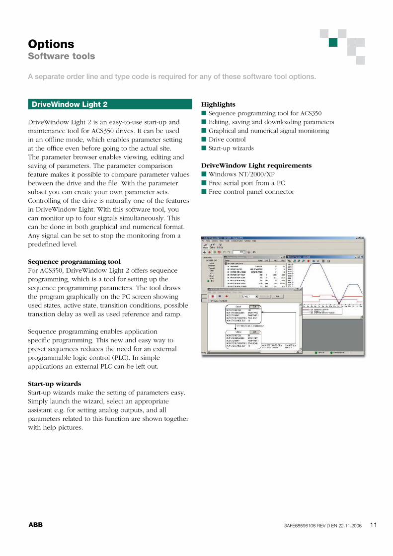
DriveWindow Light 2
DriveWindow Light 2 is an easy-to-use start-up and
maintenance tool for ACS350 drives. It can be used
in an offl ine mode, which enables parameter setting
at the offi ce even before going to the actual site.
The parameter browser enables viewing, editing and
saving of parameters. The parameter comparison
feature makes it possible to compare parameter values
between the drive and the fi le. With the parameter
subset you can create your own parameter sets.
Controlling of the drive is naturally one of the features
in DriveWindow Light. With this software tool, you
can monitor up to four signals simultaneously. This
can be done in both graphical and numerical format.
Any signal can be set to stop the monitoring from a
predefi ned level.
Sequence programming tool
For ACS350, DriveWindow Light 2 offers sequence
programming, which is a tool for setting up the
sequence programming parameters. The tool draws
the program graphically on the PC screen showing
used states, active state, transition conditions, possible
transition delay as well as used reference and ramp.
Sequence programming enables application
specifi c programming. This new and easy way to
preset sequences reduces the need for an external
programmable logic control (PLC). In simple
applications an external PLC can be left out.
Start-up wizards
Start-up wizards make the setting of parameters easy.
Simply launch the wizard, select an appropriate
assistant e.g. for setting analog outputs, and all
parameters related to this function are shown together
with help pictures.
OptionsSoftware tools
A separate order line and type code is required for any of these software tool options.
Highlights
Sequence programming tool for ACS350
Editing, saving and downloading parameters
Graphical and numerical signal monitoring
Drive control
Start-up wizards
DriveWindow Light requirements
Windows NT/2000/XP
Free serial port from a PC
Free control panel connector
n
n
n
n
n
n
n
n

3AFE68596106 REV D EN 22.11.200612 ABB
Technical data
Fuses
Standard fuses can be used with ABB general
machinery drives. For input fuse connections see table
below.
Selection table
Free space requirements
Cooling air fl ow
Cooling
ACS350 is fi tted with cooling fans as standard. The
cooling air must be free from corrosive substances and
must not be above the maximum ambient temperature
of 40oC (50oC with derating). For more specifi c limits
see the Technical specifi cation - Environmental limits
in this catalogue.
X within the type code stands for E or U.
*) Frame size R0 with free convection cooling. X within the type code stands for E or U.
*) According to IEC-60269 standard.
Type codeFrame
size
IEC Fuses UL Fuses
A
Fuse
type*)A
Fuse
type*)
1-phase supply voltage 200 - 240 V units
ACS350-01X-02A4-2 R0 10 gG 10 UL class T
ACS350-01X-04A7-2 R1 16 gG 20 UL class T
ACS350-01X-06A7-2 R1 20 gG 25 UL class T
ACS350-01X-07A5-2 R2 25 gG 30 UL class T
ACS350-01X-09A8-2 R2 35 gG 35 UL class T
3-phase supply voltage 200 - 240 V units
ACS350-03X-02A4-2 R0 10 gG 10 UL class T
ACS350-03X-03A5-2 R0 10 gG 10 UL class T
ACS350-03X-04A7-2 R1 10 gG 15 UL class T
ACS350-03X-06A7-2 R1 16 gG 15 UL class T
ACS350-03X-07A5-2 R1 16 gG 15 UL class T
ACS350-03X-09A8-2 R2 16 gG 20 UL class T
ACS350-03X-13A3-2 R2 25 gG 30 UL class T
ACS350-03X-17A6-2 R2 25 gG 35 UL class T
3-phase supply voltage 380 - 480 V units
ACS350-03X-01A2-4 R0 10 gG 10 UL class T
ACS350-03X-01A9-4 R0 10 gG 10 UL class T
ACS350-03X-02A4-4 R1 10 gG 10 UL class T
ACS350-03X-03A3-4 R1 10 gG 10 UL class T
ACS350-03X-04A1-4 R1 16 gG 15 UL class T
ACS350-03X-05A6-4 R1 16 gG 15 UL class T
ACS350-03X-07A3-4 R1 16 gG 20 UL class T
ACS350-03X-08A8-4 R1 20 gG 25 UL class T
ACS350-03X-12A5-4 R3 25 gG 30 UL class T
ACS350-03X-15A6-4 R3 35 gG 35 UL class T
ACS350-03X-23A1-4 R3 50 gG 50 UL class T
Enclosure
type
Space above
mm
Space below
mm
Space on left/right
mm
All frame sizes 75 75 0
Type codeFrame
size
Heat dissipation Air fl ow
w BTU/Hr m3/h ft
3/min
1-phase supply voltage 200 - 240 V units
ACS350-01X-02A4-2 R0 25 85 -*)
-*)
ACS350-01X-04A7-2 R1 46 157 24 14
ACS350-01X-06A7-2 R1 71 242 24 14
ACS350-01X-07A5-2 R2 73 249 21 12
ACS350-01X-09A8-2 R2 96 328 21 12
3-phase supply voltage 200 - 240 V units
ACS350-03X-02A4-2 R0 19 65 -*)
-*)
ACS350-03X-03A5-2 R0 31 106 -*)
-*)
ACS350-03X-04A7-2 R1 38 130 24 14
ACS350-03X-06A7-2 R1 60 205 24 14
ACS350-03X-07A5-2 R1 62 212 21 12
ACS350-03X-09A8-2 R2 83 283 21 12
ACS350-03X-13A3-2 R2 112 383 52 31
ACS350-03X-17A6-2 R2 152 519 52 31
3-phase supply voltage 380 - 480 V units
ACS350-03X-01A2-4 R0 11 38 -*)
-*)
ACS350-03X-01A9-4 R0 16 55 -*)
-*)
ACS350-03X-02A4-4 R1 21 72 13 8
ACS350-03X-03A3-4 R1 31 106 13 8
ACS350-03X-04A1-4 R1 40 137 13 8
ACS350-03X-05A6-4 R1 61 208 19 11
ACS350-03X-07A3-4 R1 74 253 24 14
ACS350-03X-08A8-4 R1 94 321 24 14
ACS350-03X-12A5-4 R3 130 444 52 31
ACS350-03X-15A6-4 R3 173 591 52 31
ACS350-03X-23A1-4 R3 266 908 71 42

3AFE68596106 REV D EN 22.11.2006 13ABB
Control connections
These connections are shown as examples only. Please
refer to the ACS350 User's Manual for more detailed
information.
1
2
3
4
5
6
7
8
SCR
AI1
GND
+10 V
AI2
GND
AO
GND
+24 V
GND
DCOM
DI1
DI2
DI3
DI4
DI5
9
10
11
12
13
14
15
16
17
18
19
ROCOM
RONC
RONO
DOSRC
DOOUT
DOGND
20
21
22
1
2
3
4
5
6
7
8
SCR
AI1
GND
+10 V
AI2
GND
AO
GND
9
10
11
12
13
14
15
16
+24 V
GND
DCOM
DI1
DI2
DI3
DI4
DI5
17
18
19
20
21
22
ROCOM
RONC
RONO
DOSRC
DOOUT
DOGND
ACS350
X1
ACS350
X1
DIP switch
analog inputs
DIP switch
analog inputs
0-10 V
0(4)-20 mA
AI1:
AI2:
NO
NO
0-10 V
0-10 VNO
NOAI1:
AI2:
DI confi guration
PNP connected (source)
with external power
supply
DI confi guration
NPN connected (sink)
0 - 20 mA
Ground the cable
screen on the
sourcing end
R<10 kΩ
R<10 kΩ
ramp
pair sel.
const.
speed 1
fwd/
rev
start/
stop
const.
speed 1
fwd/
rev
start/
stop
+ 24 V
1
2
3
4
SCR
AI
GND
+10 V
Analog input can also be used
with bipolar voltages:
+10 V GND -10 V
DIP switch
analog inputs
0-10 VAI1: NO
0 V
max. 30 V DC
max. 30 V DC
14 ABB3AFE68596106 REV D EN 22.11.2006
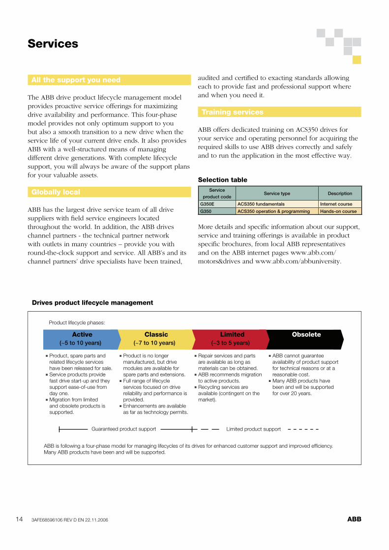
Drives product lifecycle management
Active Classic Limited Obsolete
n Product, spare parts and
related lifecycle services
have been released for sale.n Service products provide
fast drive start-up and they
support ease-of-use from
day one.n Migration from limited
and obsolete products is
supported.
n Product is no longer
manufactured, but drive
modules are available for
spare parts and extensions.n Full range of lifecycle
services focused on drive
reliability and performance is
provided.n Enhancements are available
as far as technology permits.
n Repair services and parts
are available as long as
materials can be obtained.n ABB recommends migration
to active products.n Recycling services are
available (contingent on the
market).
n ABB cannot guarantee
availability of product support
for technical reasons or at a
reasonable cost.n Many ABB products have
been and will be supported
for over 20 years.
Product lifecycle phases:
Guaranteed product support Limited product support
(~5 to 10 years) (~7 to 10 years) (~3 to 5 years)
ABB is following a four-phase model for managing lifecycles of its drives for enhanced customer support and improved effi ciency.
Many ABB products have been and will be supported.
Selection table
All the support you need
The ABB drive product lifecycle management model
provides proactive service offerings for maximizing
drive availability and performance. This four-phase
model provides not only optimum support to you
but also a smooth transition to a new drive when the
service life of your current drive ends. It also provides
ABB with a well-structured means of managing
different drive generations. With complete lifecycle
support, you will always be aware of the support plans
for your valuable assets.
Globally local
ABB has the largest drive service team of all drive
suppliers with fi eld service engineers located
throughout the world. In addition, the ABB drives
channel partners - the technical partner network
with outlets in many countries – provide you with
round-the-clock support and service. All ABB’s and its
channel partners’ drive specialists have been trained,
audited and certifi ed to exacting standards allowing
each to provide fast and professional support where
and when you need it.
Training services
ABB offers dedicated training on ACS350 drives for
your service and operating personnel for acquiring the
required skills to use ABB drives correctly and safely
and to run the application in the most effective way.
More details and specifi c information about our support,
service and training offerings is available in product
specifi c brochures, from local ABB representatives
and on the ABB internet pages www.abb.com/
motors&drives and www.abb.com/abbuniversity.
Services
Service
product codeService type Description
G350E ACS350 fundamentals Internet course
G350 ACS350 operation & programming Hands-on course