
Ab Initio Thermodynamic Study of the CO Capture Properties ... · Ab Initio Thermodynamic Study of...
10
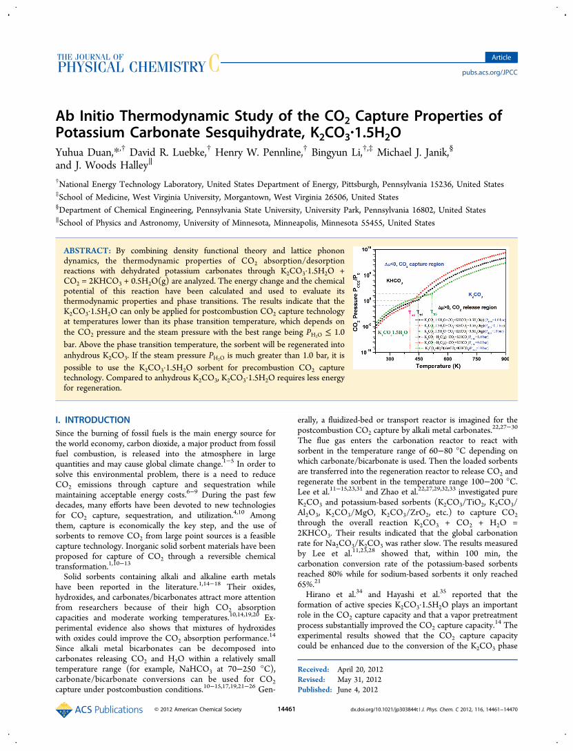
Ab Initio Thermodynamic Study of the CO 2 Capture Properties of Potassium Carbonate Sesquihydrate, K 2 CO 3 ·1.5H 2 O Yuhua Duan,* ,† David R. Luebke, † Henry W. Pennline, † Bingyun Li, †,‡ Michael J. Janik, § and J. Woods Halley ∥ † National Energy Technology Laboratory, United States Department of Energy, Pittsburgh, Pennsylvania 15236, United States ‡ School of Medicine, West Virginia University, Morgantown, West Virginia 26506, United States § Department of Chemical Engineering, Pennsylvania State University, University Park, Pennsylvania 16802, United States ∥ School of Physics and Astronomy, University of Minnesota, Minneapolis, Minnesota 55455, United States ABSTRACT: By combining density functional theory and lattice phonon dynamics, the thermodynamic properties of CO 2 absorption/desorption reactions with dehydrated potassium carbonates through K 2 CO 3 ·1.5H 2 O+ CO 2 = 2KHCO 3 + 0.5H 2 O(g) are analyzed. The energy change and the chemical potential of this reaction have been calculated and used to evaluate its thermodynamic properties and phase transitions. The results indicate that the K 2 CO 3 ·1.5H 2 O can only be applied for postcombustion CO 2 capture technology at temperatures lower than its phase transition temperature, which depends on the CO 2 pressure and the steam pressure with the best range being P H 2 O ≤ 1.0 bar. Above the phase transition temperature, the sorbent will be regenerated into anhydrous K 2 CO 3 . If the steam pressure P H 2 O is much greater than 1.0 bar, it is possible to use the K 2 CO 3 ·1.5H 2 O sorbent for precombustion CO 2 capture technology. Compared to anhydrous K 2 CO 3 ,K 2 CO 3 ·1.5H 2 O requires less energy for regeneration. I. INTRODUCTION Since the burning of fossil fuels is the main energy source for the world economy, carbon dioxide, a major product from fossil fuel combustion, is released into the atmosphere in large quantities and may cause global climate change. 1−5 In order to solve this environmental problem, there is a need to reduce CO 2 emissions through capture and sequestration while maintaining acceptable energy costs. 6−9 During the past few decades, many efforts have been devoted to new technologies for CO 2 capture, sequestration, and utilization. 4,10 Among them, capture is economically the key step, and the use of sorbents to remove CO 2 from large point sources is a feasible capture technology. Inorganic solid sorbent materials have been proposed for capture of CO 2 through a reversible chemical transformation. 1,10−13 Solid sorbents containing alkali and alkaline earth metals have been reported in the literature. 1,14−18 Their oxides, hydroxides, and carbonates/bicarbonates attract more attention from researchers because of their high CO 2 absorption capacities and moderate working temperatures. 10,14,19,20 Ex- perimental evidence also shows that mixtures of hydroxides with oxides could improve the CO 2 absorption performance. 14 Since alkali metal bicarbonates can be decomposed into carbonates releasing CO 2 and H 2 O within a relatively small temperature range (for example, NaHCO 3 at 70−250 °C), carbonate/bicarbonate conversions can be used for CO 2 capture under postcombustion conditions. 10−15,17,19,21−26 Gen- erally, a fluidized-bed or transport reactor is imagined for the postcombustion CO 2 capture by alkali metal carbonates. 22,27−30 The flue gas enters the carbonation reactor to react with sorbent in the temperature range of 60−80 °C depending on which carbonate/bicarbonate is used. Then the loaded sorbents are transferred into the regeneration reactor to release CO 2 and regenerate the sorbent in the temperature range 100−200 °C. Lee et al. 11−15,23,31 and Zhao et al. 22,27,29,32,33 investigated pure K 2 CO 3 and potassium-based sorbents (K 2 CO 3 /TiO 2 ,K 2 CO 3 / Al 2 O 3 ,K 2 CO 3 /MgO, K 2 CO 3 /ZrO 2 , etc.) to capture CO 2 through the overall reaction K 2 CO 3 + CO 2 + H 2 O = 2KHCO 3 . Their results indicated that the global carbonation rate for Na 2 CO 3 /K 2 CO 3 was rather slow. The results measured by Lee et al. 11,23,28 showed that, within 100 min, the carbonation conversion rate of the potassium-based sorbents reached 80% while for sodium-based sorbents it only reached 65%. 21 Hirano et al. 34 and Hayashi et al. 35 reported that the formation of active species K 2 CO 3 ·1.5H 2 O plays an important role in the CO 2 capture capacity and that a vapor pretreatment process substantially improved the CO 2 capture capacity. 14 The experimental results showed that the CO 2 capture capacity could be enhanced due to the conversion of the K 2 CO 3 phase Received: April 20, 2012 Revised: May 31, 2012 Published: June 4, 2012 Article pubs.acs.org/JPCC © 2012 American Chemical Society 14461 dx.doi.org/10.1021/jp303844t | J. Phys. Chem. C 2012, 116, 14461−14470
Transcript of Ab Initio Thermodynamic Study of the CO Capture Properties ... · Ab Initio Thermodynamic Study of...
Ab Initio Thermodynamic Study of the CO2 Capture Properties ofPotassium Carbonate Sesquihydrate, K2CO3·1.5H2OYuhua Duan,*,† David R. Luebke,† Henry W. Pennline,† Bingyun Li,†,‡ Michael J. Janik,§
and J. Woods Halley∥
†National Energy Technology Laboratory, United States Department of Energy, Pittsburgh, Pennsylvania 15236, United States‡School of Medicine, West Virginia University, Morgantown, West Virginia 26506, United States§Department of Chemical Engineering, Pennsylvania State University, University Park, Pennsylvania 16802, United States∥School of Physics and Astronomy, University of Minnesota, Minneapolis, Minnesota 55455, United States
ABSTRACT: By combining density functional theory and lattice phonondynamics, the thermodynamic properties of CO2 absorption/desorptionreactions with dehydrated potassium carbonates through K2CO3·1.5H2O +CO2 = 2KHCO3 + 0.5H2O(g) are analyzed. The energy change and the chemicalpotential of this reaction have been calculated and used to evaluate itsthermodynamic properties and phase transitions. The results indicate that theK2CO3·1.5H2O can only be applied for postcombustion CO2 capture technologyat temperatures lower than its phase transition temperature, which depends onthe CO2 pressure and the steam pressure with the best range being PH2O ≤ 1.0bar. Above the phase transition temperature, the sorbent will be regenerated intoanhydrous K2CO3. If the steam pressure PH2O is much greater than 1.0 bar, it ispossible to use the K2CO3·1.5H2O sorbent for precombustion CO2 capturetechnology. Compared to anhydrous K2CO3, K2CO3·1.5H2O requires less energyfor regeneration.
I. INTRODUCTIONSince the burning of fossil fuels is the main energy source forthe world economy, carbon dioxide, a major product from fossilfuel combustion, is released into the atmosphere in largequantities and may cause global climate change.1−5 In order tosolve this environmental problem, there is a need to reduceCO2 emissions through capture and sequestration whilemaintaining acceptable energy costs.6−9 During the past fewdecades, many efforts have been devoted to new technologiesfor CO2 capture, sequestration, and utilization.4,10 Amongthem, capture is economically the key step, and the use ofsorbents to remove CO2 from large point sources is a feasiblecapture technology. Inorganic solid sorbent materials have beenproposed for capture of CO2 through a reversible chemicaltransformation.1,10−13
Solid sorbents containing alkali and alkaline earth metalshave been reported in the literature.1,14−18 Their oxides,hydroxides, and carbonates/bicarbonates attract more attentionfrom researchers because of their high CO2 absorptioncapacities and moderate working temperatures.10,14,19,20 Ex-perimental evidence also shows that mixtures of hydroxideswith oxides could improve the CO2 absorption performance.14
Since alkali metal bicarbonates can be decomposed intocarbonates releasing CO2 and H2O within a relatively smalltemperature range (for example, NaHCO3 at 70−250 °C),carbonate/bicarbonate conversions can be used for CO2capture under postcombustion conditions.10−15,17,19,21−26 Gen-
erally, a fluidized-bed or transport reactor is imagined for thepostcombustion CO2 capture by alkali metal carbonates.
22,27−30
The flue gas enters the carbonation reactor to react withsorbent in the temperature range of 60−80 °C depending onwhich carbonate/bicarbonate is used. Then the loaded sorbentsare transferred into the regeneration reactor to release CO2 andregenerate the sorbent in the temperature range 100−200 °C.Lee et al.11−15,23,31 and Zhao et al.22,27,29,32,33 investigated pureK2CO3 and potassium-based sorbents (K2CO3/TiO2, K2CO3/Al2O3, K2CO3/MgO, K2CO3/ZrO2, etc.) to capture CO2through the overall reaction K2CO3 + CO2 + H2O =2KHCO3. Their results indicated that the global carbonationrate for Na2CO3/K2CO3 was rather slow. The results measuredby Lee et al.11,23,28 showed that, within 100 min, thecarbonation conversion rate of the potassium-based sorbentsreached 80% while for sodium-based sorbents it only reached65%.21
Hirano et al.34 and Hayashi et al.35 reported that theformation of active species K2CO3·1.5H2O plays an importantrole in the CO2 capture capacity and that a vapor pretreatmentprocess substantially improved the CO2 capture capacity.
14 Theexperimental results showed that the CO2 capture capacitycould be enhanced due to the conversion of the K2CO3 phase
Received: April 20, 2012Revised: May 31, 2012Published: June 4, 2012
Article
pubs.acs.org/JPCC
© 2012 American Chemical Society 14461 dx.doi.org/10.1021/jp303844t | J. Phys. Chem. C 2012, 116, 14461−14470

to the K2CO3·1.5H2O phase through the K4H2(CO3)3·1.5H2Ophase during pretreatment with sufficient water vapor.14
Shigemoto and Yanagihara25 proposed potassium carbonatesupported on an activated carbon as an efficient sorbent torecover CO2 from moist flue gas through the reactionK2CO3·1.5H2O + CO2 = 2KHCO3 + 0.5H2O. However, byusing thermogravimetric analysis (TGA) and X-ray diffraction(XRD) measurements to obtain the characteristics ofpotassium-based sorbents for CO2 capture, Zhao et al.22
found that the carbonation reactivity of K2CO3·1.5H2O andK2CO3 (in monoclinic structure and dehydrated fromK2CO3·1.5H2O) was weak, but K2CO3 (in hexagonal structure)calcined from KHCO3 showed excellent carbonation capacityand reproducibility.Although the thermodynamic properties of K2CO3 are well-
known either from databases36,37 or from our first-principlescalculations,17,18,38 in the literature, there is a lack ofthermodynamic data for K2CO3·1.5H2O. In order to evaluatethe CO2 capture performance of K2CO3·1.5H2O and tocompare with the corresponding anhydrous K2CO3, in thisstudy we apply our previous approach16,39,40 to explore theelectronic and lattice dynamic properties of K2CO3·1.5H2Ocrystal. Then, based on the calculated energetic properties, wewill calculate the thermodynamic properties of CO2 capturereactions by K2CO3·1.5H2O and K2CO3 to find the optimalworking conditions for achieving maximum capture capacity.The rest of this paper is organized as follows: section II
briefly describes the theoretical method employed. Section IIIpresents the results of the electronic structural and phononproperties of K2CO3·1.5H2O compared with the correspondinganhydrous K2CO3. Based on those properties, the thermody-namic properties of reactions of these carbonates in capturingCO2 are evaluated and their corresponding working conditionsare fully analyzed. Section IV contains a brief summary andconclusions.
II. THEORETICAL METHODSThe complete description of our computational methodologycan be found in our previous studies.16−18,38−42 Here, we limitourselves to provide only the main aspects relevant for thecurrent study. When applying hydrated and dehydratedpotassium carbonates as solid CO2 absorbents, we have thefollowing reactions:
· + ←→ +K CO 1.5H O CO 2KHCO 0.5H O(g)T P
2 3 2 2,
3 2(R1)
and
+ + ←→K CO H O(g) CO 2KHCOT P
2 3 2 2,
3 (R2)
Assuming the difference between the chemical potentials ofsolid phases (K2CO3, KCO3·1.5H2O, and KHCO3) can beapproximated by the differences in their electronic energies(ΔEDFT) and their entropies (ΔSPH) and harmonic freeenergies (ΔFPH), we can obtain the temperature- andpressure-dependent chemical potential (Δμ) for the abovereactions:16−18,38−42
μ μΔ = Δ −⎛⎝⎜⎜
⎛⎝⎜
⎞⎠⎟
⎞⎠⎟⎟T P T RT
P
P
P
P( , ) ( ) ln
n0 CO
0
H O
0
2 20
(1)
with
μΔ = Δ + Δ + Δ −
−
T E E F T G T
n G T
( ) ( ) ( )
( )
0DFT ZP PH CO
0 H O
2
2 (2)
where ΔEZP is the zero-point-energy difference between thereactants and products and can be obtained directly fromphonon calculations. P0 is the standard state reference pressureof 1 bar. For reaction R1, the n0 in eqs 1 and 2 is −0.5, whereasfor reaction R2 it is n0 = 1. The enthalpy change for reactionR1, ΔHcal(T), can be derived from eqs 1 and 2 as
μΔ = Δ + Δ −
−
H T T T S T S T
n S T
( ) ( ) ( ( ) ( )
( ))
cal 0PH CO
0 H O
2
2 (3)
As described in our previous study,16,38−41 the zero-pointenergies, the free energies, and the entropies of the gas phasesof CO2 (Ezp_CO2
, GCO2(T), SCO2
(T)) and H2O(g) (Ezp_H2O,
GH2O(T), SH2O(T)) can be obtained by standard statisticalmechanics and accurately evaluated using the Shomateequation.37 In eq 2, ΔEDFT is the total energy change of thereactants and products calculated by density functional theory(DFT). In this work, the Vienna Ab initio Simulation Package(VASP)43,44 was employed to calculate the electronic structuresof the solid materials involved in this study. All calculationshave been done using the projector augmented wave (PAW)pseudopotentials and the PW91 exchange-correlation func-tional.45 This computational level was shown to provide anaccurate description of oxide systems.16,17,40,46 Plane wave basissets were used with a cutoff energy of 500 eV and a kineticenergy cutoff for augmentation charges of 605.4 eV. The k-point sampling grids of n1 × n2 × n3, obtained using theMonkhorst−Pack method,47 were used for these bulkcalculations, where n1, n2, and n3 were determined consistentto a spacing of about 0.028 Å−1 along the axes of the reciprocalunit cells. The corresponding k-points set that we used in ourcalculations is 4 × 3 × 6 for K2CO3·1.5H2O. The valenceelectrons contain the outer s and p orbitals of H, C, and Oatoms, and the outer s, p, and d orbitals of K. During thecalculations, all atoms in the cell as well as the latticedimensions and angles were relaxed to the equilibriumconfigurations. For band structure and phonon dispersioncalculations, the symbols and coordinates of the high symmetrypoints in the first Brillouin zone of the crystals are taken fromBradley and Cracknell’s definitions.48
In eqs 2 and 3, the zero-point energies (EZP), entropies(SPH), and harmonic free energies (FPH, excluding the zero-point energy which was already counted in the term ΔEZP) ofsolids were calculated by the PHONON software package,49 inwhich the direct method is applied following the formuladerived by Parlinski et al.50 to combine ab initio DFT withlattice phonon dynamics calculations. In the phononcalculations, a 1 × 1 × 2 supercell is created forK2CO3·1.5H2O from its optimized unit cell that is calculatedthrough DFT. Based on the partition function carried out withthe phonon dispersions and phonon densities of states, theirthermodynamic properties, such as internal energy, free energy,entropy, and heat capacity, can be evaluated under differenttemperature and pressure conditions that are used in eq 1 tocalculate the chemical potentials for reactions R1 and R2, whichare further used to evaluate its CO2 capture properties aspresented in section III.C.
The Journal of Physical Chemistry C Article
dx.doi.org/10.1021/jp303844t | J. Phys. Chem. C 2012, 116, 14461−1447014462
III. RESULTS AND DISCUSSION
III.A. Electronic Structural Properties of K2CO3·1.5H2O.The original synthesis and crystal structure of potassiumcarbonate sesquihydrate, K2CO3·1.5H2O, was first reported byHunter and Jeffrey51 and further redetermined by Skakle et al.52
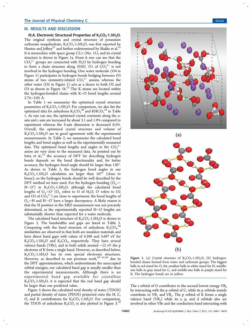
It is monoclinic with space group C2/c (No. 15), and its crystalstructure is shown in Figure 1a. From it one can see that theCO3
2− groups are connected with H2O by hydrogen bondingto form a chain structure along (010). O1 of CO3
2− is notinvolved in the hydrogen bonding. One water molecule (O4 inFigure 1) participates in hydrogen bonds bridging between O3atoms of two symmetry-related CO3
2− anions, whereas theother water (O5 in Figure 1) acts as a donor to both O2 andO3 as shown in Figure 1b.52 The K atoms are located withinthe hydrogen-bonded chains with K−O bond lengths around2.74−3.05 Å.In Table 1 we summarize the optimized crystal structure
parameters of K2CO3·1.5H2O. For comparison, we also list theoptimized data for anhydrous K2CO3
38 and KHCO318 in Table
1. As one can see, the optimized crystal constants along the a-axis and c-axis are increased by about 3.1 and 1.9% compared toexperiment whereas the b-axis dimension is decreased 0.5%.Overall, the optimized crystal structure and volume ofK2CO3·1.5H2O are in good agreement with the experimentalmeasurements. In Table 2, we summarize the calculated bondlengths and bond angles as well as the experimentally measureddata. The optimized bond lengths and angles in the CO3
2−
anion are very close to the measured data. As pointed out byIreta et al.,53 the accuracy of DFT for describing hydrogenbonds depends on the bond directionality and, for betteraccuracy, the hydrogen bond angle should be larger than 130°.As shown in Table 2, the hydrogen bond angles in ourK2CO3·1.5H2O calculation are larger than 167° (close tolinear), so the hydrogen bonds should be well described by theDFT method we have used. For the hydrogen bonding (OwH···O′) in K2CO3·1.5H2O, although the calculated bondlengths of Ow−O′ (Ow refers to O of H2O, O′ refers to O2and O3 of CO3
2−) are close to experiment, the bond lengths ofOw−H and H···O′ have a larger discrepancy. A likely reason isthat the H position in the XRD measurement was not preciselydetermined, as the experimentally reported H−O lengths aresubstantially shorter than expected for a water molecule.The calculated band structure of K2CO3·1.5H2O is shown in
Figure 2. The bandwidths and gaps are listed in Table 3.Comparing with the band structure of anhydrous K2CO3,
38
similarities are observed in that both are insulator materials andhave direct band gaps with values of 4.298 and 3.697 eV forK2CO3·1.5H2O and K2CO3, respectively. They have severalvalence bands (VBs), and in both solids around −12 eV the pelectrons of K form a single band. However, as described below,K2CO3·1.5H2O has its own special electronic structures.However, as described in our previous work,39−41,46 due tothe DFT approximations, which underestimate the unoccupiedorbital energies, our calculated band gap is usually smaller thanthe experimental measurements. Although there is noexper imenta l band gap ava i lab le for crys ta l l ineK2CO3·1.5H2O, it is expected that the real band gap shouldbe larger than our predicted value.Figure 3 shows the calculated total density of states (TDOS)
and partial density of states (PDOS) projected onto the H, C,O, and K contributions for K2CO3·1.5H2O. For comparison,the TDOS of anhydrous K2CO3 is also plotted in Figure 3.38
The s orbital of O contributes to the second lowest energy VB6by interacting with the p orbital of C, while its p orbitals mainlycontribute to VB1 and VB2. The p orbital of K forms a singlevalence band (VB5) while its s, p, and d orbitals also areinvolved in other VBs and the conduction band interacting with
Figure 1. (a) Crystal structure of K2CO3·1.5H2O; (b) hydrogen-bonded chains formed from water and carbonate groups. The biggestballs in red stand for O, the smallest balls in white stand for H, middle-size balls in gray stand for C, and middle-size balls in purple stand forK. The hydrogen bonds are in yellow.
The Journal of Physical Chemistry C Article
dx.doi.org/10.1021/jp303844t | J. Phys. Chem. C 2012, 116, 14461−1447014463
Table
1.Experim
entalandOptim
ized
Crystal
Structural
Param
etersof
K2CO
3·1.5H
2O,KHCO
3,andK2CO
3
experim
entalstructure
optim
ized
structure
crystal
spacegroup
andref
Zlatticeconst(Å)
atom
icfractio
nalcoord
latticeconstanddeviations
(%)
atom
icfractio
nalcoord
K2CO
3·1.5H
2OC12/c1
(No.
15)51,52
8a=11.8175
b=13.7466
c=7.1093
β=120.769°
K:(0.00000,0
.38193,0.25000)
(0.00000,0
.68676,0
.25000)
(0.35595,0
.349980,
0.45736)
C:(0.1929,
0.17350,
0.15183)
O:(0.10641,0
.22728,0.15315)
(0.29732,0
.15119,0
.33357)
(0.17704,0
.14186,−
0.03042)
Ow:(0.00000,−
0.00112,0.25000)
(0.14810,0
.45886,0
.0838)
H:(−
0.057,−0.0344,0.172)
(0.174,0
.5148,
0.133)
(0.189,0
.445,0
.046)
a=12.17844
(3.05)
b=13.67275
(−0.54)
c=7.243752
(1.89)
β=120.5247°(−
0.2)
K:(0.00000,0
.38210,0.25000)
(0.00000,0
.68668,0.25000)
(0.35775,0
.35627,0.46494)
C:(0.19381,0
.170529,
0.15174)
O:(0.10307,0
.22130,0
.14661)
(0.29710,0
.15112,0.33471)
(0.18347,0
.13803,−
0.02683)
Ow:(0.00000,−
0.00860,
0.25000)
(0.14759,0
.45805,0.08582)
H:(−
0.06974,
−0.05520,
0.15616)
(0.17381,0
.52755,0.12836)
(0.20930,0
.42802,0.04821)
KHCO
3aP12 1/a1
(No.
14)
4a=15.1725
b=5.6283
c=3.7110
β=104.631°
K:(0.16533,0
.02177,0.29533)
C:(0.11967,0.5150,
−0.14363)
O:(0.19329,0
.52915,0.09482)
(0.08221,0
.31998,−
0.27353)
(0.07761,0
.72772,−
0.27448)
H:(0.011,0
.682,−
0.465)
a=15.45481
(1.86)
b=5.71536(1.52)
c=3.76864(1.55)
β=105.878°
(1.19)
K:(0.16530,0
.02299,0.28726)
C:(0.11977,0
.51149,−
0.15485)
O:(0.19443,0
.52683,0
.08663)
(0.08126,0
.31928,−
0.28688)
(0.07793,0
.71698,−
0.28240)
H:(0.01434,0
.68811,−
0.45795)
K2CO
3bP12 1/c1
(No.
14)
4a=5.63961
b=9.8312
c=6.83407
β=98.703°
K:(0.2418,
0.0831,0.2148)
(0.7391,
0.2602,0
.9720)
C:(0.2455,
0.4174,0
.2489)
O:(0.7368,
0.0430,0.2014)
(0.0631,
0.3488,0
.2770)
(0.4147,
0.3609,0
.1718)
a=5.76055(2.14)
b=9.90478(0.75)
c=7.18110(5.08)
β=97.295°(−
1.42)
K:(0.24109,0
.08186,0.19586)
(0.74091,0
.26717,0.97455)
C:(0.25038,0
.41609,0.25502)
O:(0.73769,0
.04267,0
.19452)
(0.06328,0
.34645,0.27685)
(0.42479,0
.35953,0.18659)
aTaken
from
ref38.bTaken
from
refs17
and18.
The Journal of Physical Chemistry C Article
dx.doi.org/10.1021/jp303844t | J. Phys. Chem. C 2012, 116, 14461−1447014464

the s and p orbitals of C and O. From Figure 3, it can be seenthat the O of H2O (denoted as Ow in Figure 1 and Tables 1 and2) is different from the O of CO3
2−: the s orbital of Owinteracting with s and p orbitals of H forms the band VB7 inFigure 2 with lowest energy, while its p orbitals interact withorbitals of H, C, and O to form other valence bands (VB2−VB4). The s orbital of H also interacts with the p orbitals of Oof CO3
2− to form hydrogen bonds.III.B. Dynamic Phonon Properties. As shown in Table 1,
for K2CO3·1.5H2O there are eight formula units (f.u.) in its unitcell, but its primitive cell has only 4 f.u. with a total of 42 atoms.Therefore, there are 126 phonon modes in K2CO3·1.5H2O.The calculated phonon dispersion of K2CO3·1.5H2O is shownin Figure 4a. Along the wave vector L−A there is one soft modethat corresponds to the displacements of one type of O inCO3
2−.The calculated phonon densities of states of K2CO3·1.5H2O,
K2CO3,38 and KHCO3
18 are shown in Figure 4b. Compared toanhydrous K2CO3, K2CO3·1.5H2O has several extra peakswhich corresponds to H (88−95 THz) and O (45−55 THz) ofH2O-related vibrations. In KHCO3, the HCO3
− moieties form
hydrogen-bound dimers (HCO3−)2 which are separated by K+
ions.18 As shown in Figure 1, for K2CO3·1.5H2O, through thehydrogen bonding, CO3
2− anions are linked into the chainstructure with a H2O linker. Obviously, from Figure 4b, thehydrogen bonding in K2CO3·1.5H2O is weaker than that in
Table 2. Calculated Bond Lengths and Hydrogen-Bonding Geometrya
R(C−O1) R(C−O2) R(C−O3) ∠(O1−C−O2) ∠(O1−C−O3) ∠(O2−C−O3)
1.289 (1.266b) 1.310 (1.288b) 1.312 (1.296b) 120.5 (120.5b) 119.4 (119.7b) 120.1 (119.8b)OwH···O′ R(Ow−H) R(H···O′) R(Ow···O′) ∠(OwH···O′)
O4H4A···O3 1.008 (0.77c) 1.658 (1.93c) 2.652 (2.686c) 167.90O5H5A···O2 1.00 (0.83c) 1.719 (1.90c) 2.713 (2.7135c) 171.97O5H5B···O3 1.001 (0.69c) 1.662 (2.03c) 2.659 (2.6709c) 173.27
aBond lengths are in angstroms (Å) and bond angles are in degrees. bTaken from ref 51. cTaken from ref 52.
Figure 2. Calculated electronic band structure of K2CO3·1.5H2O. TheFermi level is set as relative zero.
Table 3. DFT Calculated Energies (EDFT), Band Gap, Zero-Point Energy (EZP), and Entropy (S) Calculated from Phonon andAvailable Experimental Data
S (J/mol·K)
compound space group EDFT (eV/f.u.) band gap (eV) EZP (eV/f.u.) phonon (T = 300 K) expta (T = 298.15 K)
K2CO3·1.5H2O C12/c1 (No. 15) −59.494 83 4.298 (direct) 1.492 22 217.386KHCO3
b P121/a1 (No. 14) −37.886 04 4.967 (direct) 0.760 68 122.406 115.499K2CO3
c P121/c1 (No. 14) −36.904 80 3.697 (direct) 0.457 33 160.121 155.500CO2 molecule P1 −22.994 09 0.315 98 213.388H2O molecule P1 −14.272 67 0.558 41 188.832
aTaken from HSC Chemistry Package.36 bTaken from refs 18 and 38. cTaken from refs 17 and 38.
Figure 3. Calculated total density of states (TDOS) and projectedpartial density of states (PDOS) of K2CO3·1.5H2O. For comparison,the TDOS of K2CO3 (No. 14)
17,38 is also plotted in the TDOS figure.
The Journal of Physical Chemistry C Article
dx.doi.org/10.1021/jp303844t | J. Phys. Chem. C 2012, 116, 14461−1447014465
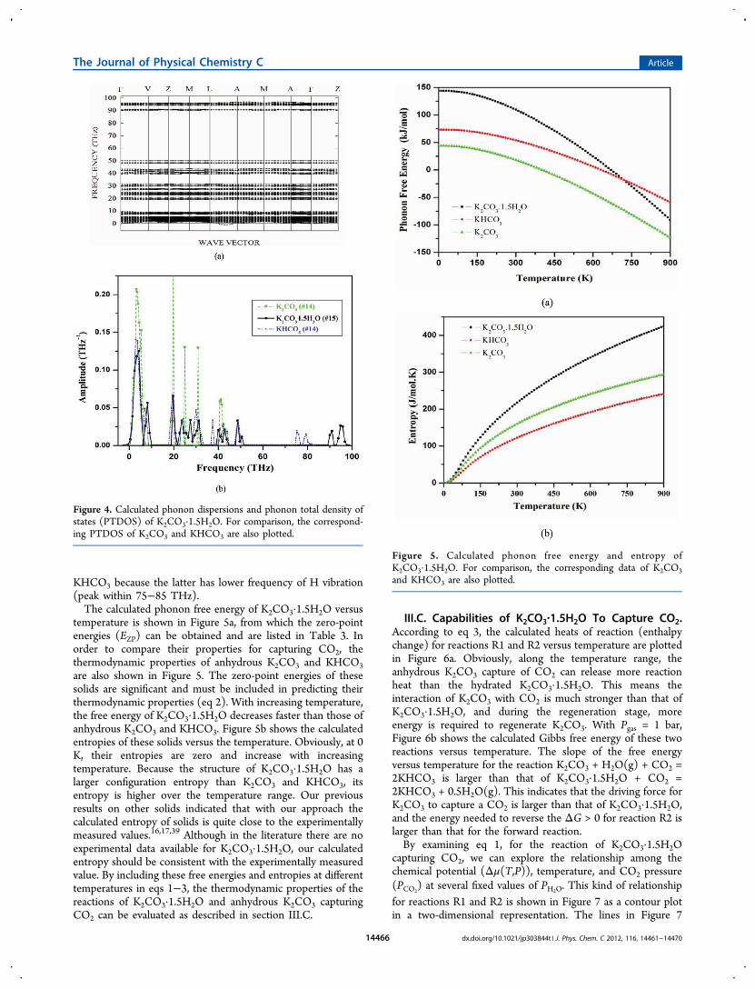
KHCO3 because the latter has lower frequency of H vibration(peak within 75−85 THz).The calculated phonon free energy of K2CO3·1.5H2O versus
temperature is shown in Figure 5a, from which the zero-pointenergies (EZP) can be obtained and are listed in Table 3. Inorder to compare their properties for capturing CO2, thethermodynamic properties of anhydrous K2CO3 and KHCO3are also shown in Figure 5. The zero-point energies of thesesolids are significant and must be included in predicting theirthermodynamic properties (eq 2). With increasing temperature,the free energy of K2CO3·1.5H2O decreases faster than those ofanhydrous K2CO3 and KHCO3. Figure 5b shows the calculatedentropies of these solids versus the temperature. Obviously, at 0K, their entropies are zero and increase with increasingtemperature. Because the structure of K2CO3·1.5H2O has alarger configuration entropy than K2CO3 and KHCO3, itsentropy is higher over the temperature range. Our previousresults on other solids indicated that with our approach thecalculated entropy of solids is quite close to the experimentallymeasured values.16,17,39 Although in the literature there are noexperimental data available for K2CO3·1.5H2O, our calculatedentropy should be consistent with the experimentally measuredvalue. By including these free energies and entropies at differenttemperatures in eqs 1−3, the thermodynamic properties of thereactions of K2CO3·1.5H2O and anhydrous K2CO3 capturingCO2 can be evaluated as described in section III.C.
III.C. Capabilities of K2CO3·1.5H2O To Capture CO2.According to eq 3, the calculated heats of reaction (enthalpychange) for reactions R1 and R2 versus temperature are plottedin Figure 6a. Obviously, along the temperature range, theanhydrous K2CO3 capture of CO2 can release more reactionheat than the hydrated K2CO3·1.5H2O. This means theinteraction of K2CO3 with CO2 is much stronger than that ofK2CO3·1.5H2O, and during the regeneration stage, moreenergy is required to regenerate K2CO3. With Pgas = 1 bar,Figure 6b shows the calculated Gibbs free energy of these tworeactions versus temperature. The slope of the free energyversus temperature for the reaction K2CO3 + H2O(g) + CO2 =2KHCO3 is larger than that of K2CO3·1.5H2O + CO2 =2KHCO3 + 0.5H2O(g). This indicates that the driving force forK2CO3 to capture a CO2 is larger than that of K2CO3·1.5H2O,and the energy needed to reverse the ΔG > 0 for reaction R2 islarger than that for the forward reaction.By examining eq 1, for the reaction of K2CO3·1.5H2O
capturing CO2, we can explore the relationship among thechemical potential (Δμ(T,P)), temperature, and CO2 pressure(PCO2
) at several fixed values of PH2O. This kind of relationshipfor reactions R1 and R2 is shown in Figure 7 as a contour plotin a two-dimensional representation. The lines in Figure 7
Figure 4. Calculated phonon dispersions and phonon total density ofstates (PTDOS) of K2CO3·1.5H2O. For comparison, the correspond-ing PTDOS of K2CO3 and KHCO3 are also plotted.
Figure 5. Calculated phonon free energy and entropy ofK2CO3·1.5H2O. For comparison, the corresponding data of K2CO3and KHCO3 are also plotted.
The Journal of Physical Chemistry C Article
dx.doi.org/10.1021/jp303844t | J. Phys. Chem. C 2012, 116, 14461−1447014466

indicate conditions at which Δμ(T,P) = 0. Near these lines is agood region for energy-efficient absorption and desorptionbecause of the minimal energy costs at the given temperatureand pressure. Above these lines in Figure 7 (Δμ(T,P) < 0), thesolids K2CO3·1.5H2O and K2CO3 are respectively favored toabsorb CO2 and to form KHCO3, while below these lines(Δμ(T,P) < 0) KHCO3 is favored to release CO2, regeneratingthe solid sorbent.From Figure 7 one can see that at each fixed PH2O these two
lines of the reactions for K2CO3·1.5H2O and K2CO3·1.5H2Ocapturing CO2 cross at a transition temperature (Ttr), whichmeans that at this temperature there is a phase transitionK2CO3·1.5H2O ↔ K2CO3 + 1.5H2O happening. Obviously, ateach fixed PH2O, the Ttr is fixed and does not depend on PCO2
asshown with vertical lines in Figure 7. Therefore, in Figure 7 thephase diagram has three regions corresponding to three solidphases: the region below Ttr and under the line isK2CO3·1.5H2O, the region above Ttr and under the line isK2CO3, while the rest of the region above the lines is theKHCO3 phase. In other words, below Ttr only reaction R1 canhappen and only K2CO3·1.5H2O could be regenerated, whileabove Ttr reaction R2 can happen and anhydrous K2CO3 couldbe regenerated.
As shown in Figure 7 and eq 1, Δμ(T,P) is dependent notonly on temperature but also on gas pressure (Pgas). Forreaction R1 Pgas= PCO2
/(PH2OP0)1/2, while for reaction R2 Pgas =
PCO2PH2O/P0
2, where P0 = 1 bar is the reference pressure. Even
with the same PCO2, PH2O plays a different role in reactions R1
and R2. The behavior can be discussed in more detail by settingPH2O at several values giving different scenarios as shown inFigure 7.(i) The first scenario is PH2O = 1.0 bar, which corresponds to
the saturation pressure of water vapor at 100 °C. In this case,the Pgas values for reactions R1 and R2 are the same and equalPCO2
. From Figure 7, these two lines cross at Ttr1 = 445 K (172°C), which means above this temperature (Ttr1) the hydratedK2CO3·1.5H2O will be dehydrated to K2CO3 through the phasetransition reaction of K2CO3·1.5H2O ↔ K2CO3 + 1.5H2O,which agrees with the experimental findings that hydrates ofK2CO3·1.5H2O can be stable up to 153 °C at ambientatmosphere condition.51 As one can see from Figure 7, both ofthese reactions are thermodynamically favorable over a widerange of temperature and PCO2
, which means that under thistemperature range the absorption of CO2 is thermodynamicallyfavored by K2CO3 and K2CO3·1.5H2O.However, as a CO2 solid sorbent, it should not only be easy
to absorb CO2 in the capture cycle but also be easy to releasethe CO2 during the regeneration cycle. The operatingconditions for absorption/desorption processes depend ontheir use in a pre- or a postcombustion application. The U.S.Department of Energy (DOE) programmatic goal forpostcombustion and oxy-combustion CO2 capture is to captureat least 90% of the CO2 produced by a plant with the cost inelectricity increasing no more than 35%, whereas the goal in thecase of precombustion CO2 capture is to capture at least 90% ofthe CO2 produced with the cost in electricity increasing nomore than 10%.54−56 Under precombustion conditions, afterthe water gas shift reactor, the gas stream mainly contains CO2,H2O, and H2. The partial CO2 pressure could be as high as 20−
Figure 6. Calculated thermodynamic properties of K2CO3·1.5H2O andK2CO3 reacting with CO2. (a) Heat of reaction versus temperature;(b) Gibbs free energy versus temperature.
Figure 7. Contour plots of calculated chemical potentials (Δμ) versustemperatures and CO2 pressures at several fixed H2O pressures andtemperatures for K2CO3·1.5H2O and K2CO3
17,18,38 capturing CO2.The y-axis is given in logarithmic scale. Only Δμ = 0 curves withdifferent fixed PH2O values are shown explicitly. For each reaction,
above the Δμ = 0 curve, the carbonates absorb CO2 and the reactiongoes forward (Δμ < 0 region) to form bicarbonate, whereas below theΔμ = 0 curve, the bicarbonate releases CO2 and the reaction goesbackward to regenerate the carbonates (Δμ > 0 region).
The Journal of Physical Chemistry C Article
dx.doi.org/10.1021/jp303844t | J. Phys. Chem. C 2012, 116, 14461−1447014467

30 bar, and the temperature is around 313−573 K. Tominimize the energy consumption, the ideal sorbents shouldwork in these pressure and temperature ranges to separate CO2from H2. The temperature denoted T1 and listed in Table 4 isthe temperature above which the sorbent solids cannot absorbCO2 and will start to release CO2. This indicates that, duringthe capture cycle, the operating temperature should be lowerthan T1, whereas the temperature may be higher than T1(depending on the desired CO2 pressure) during theregeneration cycle. Under postcombustion conditions, the gasstream mainly contains CO2 and N2, the partial pressure ofCO2 is in the range 0.1−0.2 bar, and the temperature range(T2) is quite different. Currently, in postcombustion CO2capture technology, the amine-based solvents and carbon-and zeolite-based solid sorbents (including metal organicframework) capture CO2 within a lower temperature range(<200 °C),4 while oxides (CaO, Na2O, etc.) and salts (Li4SiO4,Li2ZrO3, etc.) capture CO2 usually within a higher temperaturerange (>400 °C).4,16,17,39−41
The turnover temperatures (denoted as T1 and T2) for pre-and postcombustion capture by K2CO3·1.5H2O and K2CO3, aswell as their phase transition temperatures (Ttr), are listed inTable 4. For K2CO3·1.5H2O, T1 and T2 are 580 and 370 K,respectively. As discussed above and shown in Figure 6,K2CO3·1.5H2O can only be stable below Ttr1 = 445 K. Since itsT1 > Ttr1, K2CO3·1.5H2O cannot be used for precombustionCO2 capture technology, but can be applied to postcombustionCO2 capture technology because its T2 < Ttr1. As shown inFigure 7, K2CO3 could be used for both post- andprecombustion CO2 capture technologies. However, if theoperating temperature for the regeneration step is lower thanTtr1, KHCO3 will be first regenerated into K2CO3·1.5H2O, notK2CO3. When the operating temperature is higher than Ttr1,KHCO3 will be first regenerated into K2CO3, notK2CO3·1.5H2O, regardless of whether the initial solid sorbentis K2CO3·1.5H2O or K2CO3.(ii) The second scenario for showing the role of PH2O in
reactions R1 and R2 is when PH2O < 1.0 bar, which correspondsto the saturation pressure of water vapor below 100 °C. Herewe only discuss one example with PH2O = 0.1 bar, whichcorresponds to the saturation pressure of water vapor at around47 °C. In this case, the gas pressure (Pgas) is different forreactions R1 and R2: Pgas
R1 = PCO2
R1 /(PH2OP0)1/2 and Pgas
R2 =
PCO2
R2 PH2O/P02. From this one can see that, with decreasing PH2O,
PCO2
R1 < PCO2
R2 under the same Pgas. Therefore, compared with casei, with black lines in Figure 7, in this case (red lines) the Δμ = 0curve of reaction R1 for K2CO3·1.5H2O capturing CO2 shifted
down while the Δμ = 0 curve of reaction R2 for K2CO3capturing CO2 moved up. Hence, it can be expected that thephase transition temperature (Ttr2) of K2CO3·1.5H2O intoK2CO3 could be lower when PH2O is decreased. Indeed, fromFigure 7, the calculated Ttr2 is 395 K, which is lower than Ttr1 =445 K. At Ttr2 = 395 K, the corresponding CO2 pressure isabout 0.1 bar, which matches the postcombustion CO2 pressurecondition. Therefore, although it is not suitable forprecombustion CO2 capture since its T1 = 665 K > Ttr2 =395 K, compared to case i, K2CO3·1.5H2O may still be used forpostcombustion CO2 capture technology with lower operatingtemperature (≤395 K, when PH2O ≤ 0.1 bar) as its T2 = 395 K
≈ Ttr2. By increasing PH2O from 0.1 to 1 bar (Figure 7), Ttr2
could reach Ttr1. Again, similar to case i shown in Figure 7, ifthe regeneration operating temperature is higher than Ttr2, onlyanhydrous K2CO3 can be obtained. As shown in Table 4, thecorresponding T1 and T2 for K2CO3 are 455 and 395 K,respectively. This means that under this steam pressure K2CO3is only suitable for precombustion CO2 capture whileK2CO3·1.5H2O could be used for postcombustion CO2 capturetechnology. If one expects to regenerate K2CO3·1.5H2O, theoperating regeneration temperature must be lower than Ttr2. Inother words, case ii serves as the low end for the steampressure, which means that, in order to use K2CO3·1.5H2O asCO2 sorbent, the steam pressure should be higher than 0.1 bar.(iii) The last scenario is when PH2O > 1.0 bar, which
corresponds to the saturation pressure of water vapor above100 °C. Here we also discuss one example of PH2O = 10 bar. Inthis case, Pgas is also different for reactions R1 and R2: Pgas
R1 =PCO2
/(PH2OP0)1/2 and Pgas
R2 = PCO2PH2O/P0
2. With increasing
PH2O, PCO2
R1 is greater than PCO2
R2 under the same Pgas. Comparedwith cases i and ii, it can be expected that the phase transitiontemperature of K2CO3·1.5H2O into K2CO3 could be higherwhen PH2O was increased, because the Δμ = 0 curve of reactionR1 for K2CO3·1.5H2O capturing CO2 moved up while the Δμ= 0 curve of reaction R2 for K2CO3 capturing CO2 shifteddown as shown by the green lines in Figure 7. Indeed, Ttr3 =515 K is greater than Ttr1 = 445 K. Compared to case i, whenK2CO3·1.5H2O is used for postcombustion CO2 capturetechnology, its highest absorption temperature is around T2 =335 K and its regenerating temperature range is 335−515 K.Above Ttr3 = 515 K, the regenerated solid is anhydrous K2CO3,not K2CO3·1.5H2O. When K2CO3·1.5H2O is used as sorbentfor precombustion CO2 capture technology, its highestabsorption temperature is around T1 = 510 K and itsregenerating temperature range is very narrow with 510−515
Table 4. Calculated Thermodynamic Properties of Reactions of CO2 Captured by Hydrated and Dehydrated PotassiumCarbonates (in kJ/mol); Highest Temperature for Carbonates Capturing CO2 at Precombustion (T1) (PCO2
= 20 bar) and
Postcombustion (T2) (PCO2= 0.1 bar) Conditions and Phase Transition Temperature (Ttr) of K2CO3·1.5H2O into K2CO3
reaction CO2 (wt %) ΔEDFT ΔEZP ΔH(T = 300 K) ΔG(T = 300 K) T1 (K) T2 (K) Ttr (K)
· + = +K CO 1.5H O CO 2KHCO 0.5H O(g)2 3 2 2 3 2 26.88 −40.474 −0.737 −40.678 −12.820 580b 370b 445b
665c 395c 395c
510d 335d 515d
+ + =K CO CO H O(g) 2KHCO2 3 2 2 3 31.84 −154.429 18.293 −141.728 −46.281 490b 420b
−142.854a −44.716a 455c 395c
515d 445d
aCalculated by HSC Chemistry package.36 bWhen PH2O = 1 bar. cWhen PH2O = 0.1 bar. dWhen PH2O = 10 bar.
The Journal of Physical Chemistry C Article
dx.doi.org/10.1021/jp303844t | J. Phys. Chem. C 2012, 116, 14461−1447014468
K if we want to obtain a high pressure of CO2 (≈20 bar asbefore the capture). Above Ttr3 = 515 K, instead of regeneratingK2CO3·1.5H2O, anhydrous K2CO3 will be obtained. Below Ttr3= 515 K, regenerating K2CO3·1.5H2O is possible, but with lowreleased CO2 pressure. In conclusion, at high steam pressure (atleast >1.0 bar), K2CO3·1.5H2O could be used as CO2 sorbentfor both post- and precombustion CO2 capture technologies.Overall, from Figure 7 one can see that decreasing PH2O will
enhance the ability of K2CO3·1.5H2O to capture CO2 andmove its turnover temperature higher because, as shown inreaction R1, H2O is on the product side. For the case ofanhydrous K2CO3, decreasing PH2O will weaken its capacity forCO2 capture and move its turnover temperature lower as listedin Table 4 because, as shown in reaction R2, H2O is on thereactant side. The phase transition temperature ofK2CO3·1.5H2O into K2CO3 increases with increase of thesteam pressure PH2O. In order to use K2CO3·1.5H2O as anefficient CO2 sorbent in postcombustion capture technology,the best steam pressure range should be less than 1.0 bar, whilein precombustion CO2 capture technology, the best steampressure range should be greater than 1.0 bar.
IV. CONCLUSIONS
By combining density functional theory and phonon latticedynamics, the electronic structural and phonon properties ofK2CO3·1.5H2O were investigated. The optimized structure ofthis solid is in good agreement with experimental measure-ments. K2CO3·1.5H2O has a direct band gap of 4.298 eV.Similar to K2CO3, the p orbital of K forms a single valenceband. Different from the O of CO3
2−, the s orbital of Ow inH2O interacts with s and p orbitals of H to form a band withthe lowest energy, while its p orbitals interact with orbitals of H,C, and O to form other valence bands. The hydrogen bond inK2CO3·1.5H2O is formed by interacting the s orbital of H withp orbitals of O of CO3
2−.The phonon dispersions and phonon density of states for
K2CO3·1.5H2O were calculated by the direct method. Amongits 126 phonon modes, one soft mode along the wave vectorL−A was found and corresponded to one type of Odisplacement.From the calculated thermodynamic properties of
K2CO3·1.5H2O and K2CO3 reacting with CO2 throughreactions K2CO3·1.5H2O + CO2 = 2KHCO3 + 0.5H2O(g)and K2CO3 + H2O(g) + CO2 = 2KHCO3, it was found that theK2CO3·1.5H2O is better applied for postcombustion CO2capture technology at a temperature lower than its phasetransition temperature which depends on the CO2 pressure andthe steam pressure (PH2O ≤ 1.0 bar). When PH2O > 1.0 bar, it ispossible to use K2CO3·1.5H2O sorbent for precombustion CO2capture. Above the phase transition temperature, the sorbentwill be regenerated into anhydrous K2CO3. Compared toK2CO3, K2CO3·1.5H2O requires less energy for regeneration.
■ AUTHOR INFORMATION
Corresponding Author*Tel.: (412) 386-5771. Fax: (412) 386-5920. E-mail: [email protected].
NotesThe authors declare no competing financial interest.
■ ACKNOWLEDGMENTS
Y.D. expresses his gratitude to D. C. Sorescu for fruitfuldiscussions.
■ REFERENCES(1) Aaron, D.; Tsouris, C. Sep. Sci. Technol. 2005, 40, 321.(2) White, C. M.; Strazisar, B. R.; Granite, E. J.; Hoffman, J. S.;Pennline, H. W. J. Air Waste Manage. Assoc. 2003, 53, 645.(3) Pires, J. C. M.; Martins, F. G.; Alvim-Ferraz, M. C. M.; Simoes,M. Chem. Eng. Res. Des. 2011, 89, 1446.(4) Wang, Q.; Luo, J.; Zhong, Z.; Borgna, A. Energy Environ. Sci.2011, 4, 42.(5) Wang, S. P.; Yan, S. L.; Ma, X. B.; Gong, J. L. Energy Environ. Sci.2011, 4, 3805.(6) Pennline, H. W.; Luebke, D. R.; Jones, K. L.; Myers, C. R.; Morsi,B. I.; Heintz, Y. J.; Ilconich, J. B. Fuel Process. Technol. 2008, 89, 897.(7) Ochoa-Fernandez, E.; Rusten, H. K.; Jakobsen, H. A.; Ronning,M.; Holmen, A.; Chen, D. Catal. Today 2005, 106, 41.(8) Haszeldine, R. S. Science 2009, 325, 1647.(9) Allen, M. R.; Frame, D. J.; Huntingford, C.; Jones, C. D.; Lowe, J.A.; Meinshausen, M.; Meinshausen, N. Nature 2009, 458, 1163.(10) Hoffman, J. S.; Pennline, H. W. Investigation of CO2 CaptureUsing Regenerable Sorbents. In Proceedings of the 17th AnnualInternational Pittsburgh Coal Conference, Pittsburgh, PA, 2000; p P3_7.(11) Lee, S. C.; Chae, H. J.; Lee, S. J.; Choi, B. Y.; Yi, C. K.; Lee, J. B.;Ryu, C. K.; Kim, J. C. Environ. Sci. Technol. 2008, 42, 2736.(12) Lee, S. C.; Choi, B. Y.; Lee, S. J.; Jung, S. Y.; Ryu, C. K.; Kim, J.C. Stud. Surf. Sci. Catal. 2004, 153, 527.(13) Lee, S. C.; Choi, B. Y.; Lee, T. J.; Ryu, C. K.; Soo, Y. S.; Kim, J.C. Catal. Today 2006, 111, 385.(14) Lee, S. C.; Kim, J. C. Catal. Surv. Asia 2007, 11, 171.(15) Lee, S. C.; Chae, H. J.; Lee, S. J.; Park, Y. H.; Ryu, C. K.; Yi, C.K.; Kim, J. C. J. Mol. Catal. B: Enzym. 2009, 56, 179.(16) Duan, Y.; Sorescu, D. C. J. Chem. Phys. 2010, 133, 074508.(17) Duan, Y.; Zhang, B.; Sorescu, D. C.; Johnson, J. K. J. Solid StateChem. 2011, 184, 304.(18) Duan, Y.; Zhang, B.; Sorescu, D. C.; Johnson, J. K.; Majzoub, E.H.; Luebke, D. Density functional theory studies on the electronic,structural, phonon dynamical and thermo-stability properties ofbicarbonates MHCO3, M = Li, Na, K. J. Phys.: Condens. Matter 2012.(19) Dutcher, B.; Fan, M.; Leonard, B.; Dyar, M. D.; Tang, J.;Speicher, E. A.; Liu, P.; Zhang, Y. J. Phys. Chem. C 2011, 115, 15532.(20) Dutcher, B.; Fan, M. H.; Leonard, B. Sep. Purif. Technol. 2011,80, 364.(21) Liang, Y.; Harrison, D. P.; Gupta, R. P.; Green, D. A.;McMichael, W. J. Energy Fuels 2004, 18, 569.(22) Zhao, C. W.; Chen, X. P.; Zhao, C. S.; Liu, Y. K. Energy Fuels2009, 23, 1766.(23) Lee, J. B.; Ryu, C. K.; Baek, J. I.; Lee, J. H.; Eom, T. H.; Kim, S.H. Ind. Eng. Chem. Res. 2008, 47, 4465.(24) Park, Y. C.; Jo, S. H.; Ryu, C. K.; Yi, C. K. Energy Procedia 2009,1, 1235.(25) Shigemoto, N.; Yanagihara, T.; Sugiyama, S.; Hayashi, H. EnergyFuels 2006, 20, 721.(26) Chi, Z. Y.; O’Fallon, J. V.; Chen, S. L. Trends Biotechnol. 2011,29, 537.(27) Zhao, C. W.; Chen, X. P.; Zhao, C. S. Energy Fuels 2009, 23,4683.(28) Zhao, C. W.; Chen, X. P.; Zhao, C. S. Int. J. Greenhouse GasControl 2010, 4, 655.(29) Zhao, C. W.; Chen, X. P.; Zhao, C. S. Ind. Eng. Chem. Res. 2010,49, 12212.(30) Zhao, C. W.; Chen, X. P.; Zhao, C. S. Ind. Eng. Chem. Res. 2011,50, 4464.(31) Lee, S. C.; Chae, H. J.; Kwon, Y. M.; Lee, W. S.; Nam, H. S.;Jung, S. Y.; Lee, J. B.; Ryu, C. K.; Kim, J. C. J. Nanoelectron.Optoelectron. 2010, 5, 212.
The Journal of Physical Chemistry C Article
dx.doi.org/10.1021/jp303844t | J. Phys. Chem. C 2012, 116, 14461−1447014469

(32) Li, L.; Li, Y.; Wen, X.; Wang, F.; Zhao, N.; Xiao, F. K.; Wei, W.;Sun, Y. H. Energy Fuels 2011, 25, 3835.(33) Zhao, C. W.; Chen, X. P.; Zhao, C. S. Energy Fuels 2012, 26,1401.(34) Hirano, S.; Shigemoto, N.; Yamada, S.; Hayashi, H. Bull. Chem.Soc. Jpn. 1995, 68, 1030.(35) Hayashi, H.; Taniuchi, J.; Furuyashiki, N.; Sugiyama, S.; Hirano,S.; Shigemoto, N.; Nonaka, T. Ind. Eng. Chem. Res. 1998, 37, 185.(36) HSC Chemistry software 6.1; Outotec Research Oy, Pori,Finland; www.outotec.com/hsc, 2006.(37) Chase, M. W. J. J. Phys. Chem. Ref. Data, Monogr. 1998, 9, 1.(38) Duan, Y. J. Renewable Sustainable Energy 2012, 4, 013109.(39) Duan, Y.; Parlinski, K. Phys. Rev. B 2011, 84, 104113.(40) Duan, Y.; Sorescu, D. C. Phys. Rev. B 2009, 79, 014301.(41) Duan, Y. J. Renewable Sustainable Energy 2011, 3, 013102.(42) Zhang, B.; Duan, Y.; Johnson, J. K. J. Chem. Phys. 2012, 136,064516.(43) Kresse, G.; Hafner, J. Phys. Rev. B 1993, 47, 558.(44) Kresse, G.; Furthmuller, J. Phys. Rev. B 1996, 54, 11169.(45) Perdew, J. P.; Wang, Y. Phys. Rev. B 1992, 45, 13244.(46) Duan, Y. Phys. Rev. B 2008, 77, 045332.(47) Monkhorst, H. J.; Pack, J. D. Phys. Rev. B 1976, 13, 5188.(48) Bradley, C. J.; Cracknell, A. P. The Mathematical Theory ofSymmetry in Solids; Clarendon Press: Oxford, U.K., 1972.(49) Parlinski, K. Software PHONON, 2010.(50) Parlinski, K.; Li, Z. Q.; Kawazoe, Y. Phys. Rev. Lett. 1997, 78,4063.(51) Hunter, F. D.; Jeffrey, G. A. J. Chem. Phys. 1967, 47, 3297.(52) Skakle, J. M. S.; Wilson, M.; Feldmann, J. Acta Crystallogr., Sect.E 2001, 57, I94.(53) Ireta, J.; Neugebauer, J.; Scheffler, M. J. Phys. Chem. A 2004,108, 5692.(54) DOE-NETL. Cost and Performance Baseline for Fossil EnergyPlants, Vol. 1: Bituminous Coal and Natural Gas to Electricity FinalReport; http://www.netl.doe.gov/energy-analyses/baseline_studies.html, 2007.(55) Figueroa, J. D.; Fout, T.; Plasynski, S.; McIlvried, H.; Srivastava,R. D. Int. J. Greenhouse Gas Control 2008, 2, 9.(56) DOE/NETL. Carbon Dioxide Capture and Storage RD&DRoadmap; http://www.netl.doe.gov/technologies/carbon_seq/refshelf/CCSRoadmap.pdf, 2010.
The Journal of Physical Chemistry C Article
dx.doi.org/10.1021/jp303844t | J. Phys. Chem. C 2012, 116, 14461−1447014470