1756-rm085_-Converting PLC-5 or SLC 500 Logic to Logix-Based Logicen-p
Upload
ravindra-angalCategory
view
34download
3description
Installation Instructions
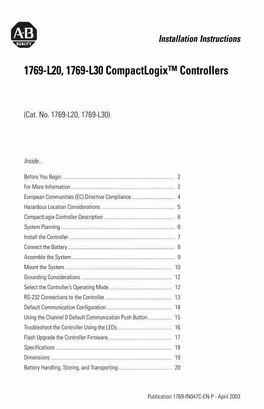
1769-L20, 1769-L30 CompactLogix™ Controllers
(Cat. No. 1769-L20, 1769-L30)
Inside...
Before You Begin .................................................................................... 2
For More Information.............................................................................. 2
European Communities (EC) Directive Compliance ................................ 4
Hazardous Location Considerations ....................................................... 5
CompactLogix Controller Description ..................................................... 6
System Planning ..................................................................................... 6
Install the Controller ............................................................................... 7
Connect the Battery ................................................................................ 8
Assemble the System ............................................................................. 9
Mount the System ................................................................................ 10
Grounding Considerations .................................................................... 12
Select the Controller’s Operating Mode ............................................... 12
RS-232 Connections to the Controller .................................................. 13
Default Communication Configuration ................................................. 14
Using the Channel 0 Default Communication Push Button .................. 15
Troubleshoot the Controller Using the LEDs......................................... 16
Flash Upgrade the Controller Firmware................................................ 17
Specifications ....................................................................................... 18
Dimensions ........................................................................................... 19
Battery Handling, Storing, and Transporting ........................................ 20
Publication 1769-IN047C-EN-P - April 2003
2 1769-L20, 1769-L30 CompactLogix™ Controllers
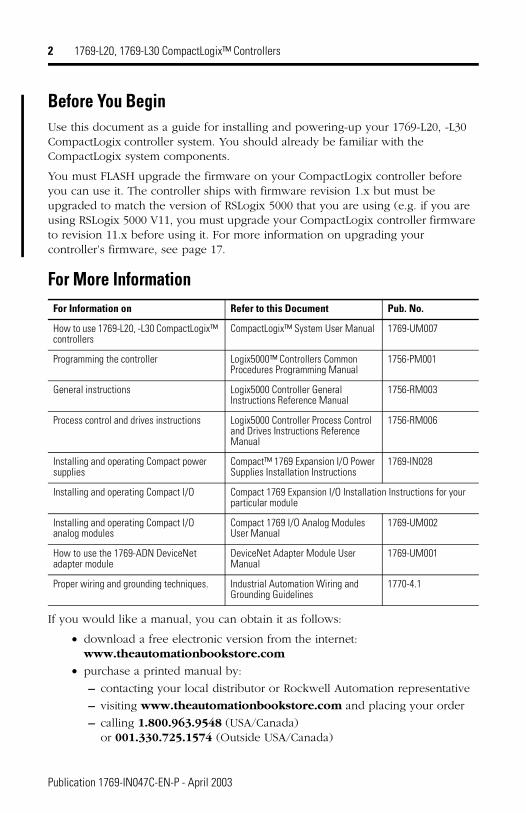
Before You BeginUse this document as a guide for installing and powering-up your 1769-L20, -L30 CompactLogix controller system. You should already be familiar with the CompactLogix system components.
You must FLASH upgrade the firmware on your CompactLogix controller before you can use it. The controller ships with firmware revision 1.x but must be upgraded to match the version of RSLogix 5000 that you are using (e.g. if you are using RSLogix 5000 V11, you must upgrade your CompactLogix controller firmware to revision 11.x before using it. For more information on upgrading your controller’s firmware, see page 17.
For More Information
If you would like a manual, you can obtain it as follows:
� download a free electronic version from the internet: �www.theautomationbookstore.com
� purchase a printed manual by:
– contacting your local distributor or Rockwell Automation representative
– visiting www.theautomationbookstore.com and placing your order
– calling 1.800.963.9548 (USA/Canada) �or 001.330.725.1574 (Outside USA/Canada)
For Information on Refer to this Document Pub. No.
How to use 1769-L20, -L30 CompactLogix™ controllers
CompactLogix™ System User Manual 1769-UM007
Programming the controller Logix5000™ Controllers Common Procedures Programming Manual
1756-PM001
General instructions Logix5000 Controller General Instructions Reference Manual
1756-RM003
Process control and drives instructions Logix5000 Controller Process Control and Drives Instructions Reference Manual
1756-RM006
Installing and operating Compact power supplies
Compact™ 1769 Expansion I/O Power Supplies Installation Instructions
1769-IN028
Installing and operating Compact I/O Compact 1769 Expansion I/O Installation Instructions for your particular module
Installing and operating Compact I/O analog modules
Compact 1769 I/O Analog Modules User Manual
1769-UM002
How to use the 1769-ADN DeviceNet adapter module
DeviceNet Adapter Module User Manual
1769-UM001
Proper wiring and grounding techniques. Industrial Automation Wiring and Grounding Guidelines
1770-4.1
Publication 1769-IN047C-EN-P - April 2003
1769-L20, 1769-L30 CompactLogix™ Controllers 3
Important User Information
Because of the variety of uses for the products described in this publication, those responsible for the application and use of these products must satisfy themselves that all necessary steps have been taken to assure that each application and use meets all performance and safety requirements, including any applicable laws, regulations, codes and standards. In no event will Rockwell Automation be responsible or liable for indirect or consequential damage resulting from the use or application of these products.
Any illustrations, charts, sample programs, and layout examples shown in this publication are intended solely for purposes of example. Since there are many variables and requirements associated with any particular installation, Rockwell Automation does not assume responsibility or liability (to include intellectual property liability) for actual use based upon the examples shown in this publication.
Allen-Bradley publication SGI-1.1, Safety Guidelines for the Application, Installation and Maintenance of Solid-State Control (available from your local Rockwell Automation office), describes some important differences between solid-state equipment and electromechanical devices that should be taken into consideration when applying products such as those described in this publication.
Reproduction of the contents of this copyrighted publication, in whole or part, without written permission of Rockwell Automation, is prohibited.
Throughout this publication, notes may be used to make you aware of safety considerations. The following annotations and their accompanying statements help you to identify a potential hazard, avoid a potential hazard, and recognize the consequences of a potential hazard:
!WARNING
Identifies information about practices or circumstances that can cause an explosion in a hazardous environment, which may lead to personal injury or death, property damage, or economic loss.
ATTENTION
!Identifies information about practices or circumstances that can lead to personal injury or death, property damage, or economic loss.
IMPORTANT Identifies information that is critical for successful application and understanding of the product.
Publication 1769-IN047C-EN-P - April 2003
4 1769-L20, 1769-L30 CompactLogix™ Controllers
European Communities (EC) Directive ComplianceIf this product has the CE mark it is approved for installation within the European Union and EEA regions. It has been designed and tested to meet the following directives.
EMC DirectiveThis product is tested to meet the Council Directive 89/336/EC Electromagnetic Compatibility (EMC) by applying the following standards, in whole or in part, documented in a technical construction file:
� EN 50081-2 EMC — Generic Emission Standard, Part 2 — Industrial Environment
� EN 50082-2 EMC — Generic Immunity Standard, Part 2 — Industrial Environment
This product is intended for use in an industrial environment.
Low Voltage DirectiveThis product is tested to meet Council Directive 73/23/EEC Low Voltage, by applying the safety requirements of EN 61131-2 Programmable Controllers, Part 2 - Equipment Requirements and Tests. For specific information required by �EN 61131-2, see the appropriate sections in this publication, as well as the Allen-Bradley publication Industrial Automation Wiring and Grounding Guidelines For Noise Immunity, publication 1770-4.1. and the Automation Systems Catalog, publication B111.
This equipment is classified as open equipment and must be mounted in an enclosure during operation to provide safety protection.
Publication 1769-IN047C-EN-P - April 2003
1769-L20, 1769-L30 CompactLogix™ Controllers 5
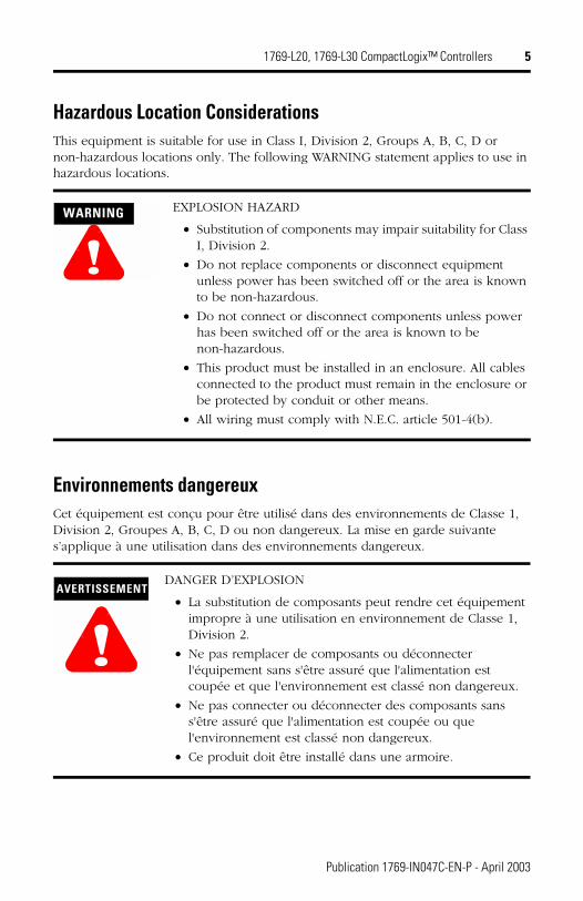
Hazardous Location ConsiderationsThis equipment is suitable for use in Class I, Division 2, Groups A, B, C, D or non-hazardous locations only. The following WARNING statement applies to use in hazardous locations.
Environnements dangereuxCet équipement est conçu pour être utilisé dans des environnements de Classe 1, Division 2, Groupes A, B, C, D ou non dangereux. La mise en garde suivante s’applique à une utilisation dans des environnements dangereux.
!WARNING EXPLOSION HAZARD
� Substitution of components may impair suitability for Class I, Division 2.
� Do not replace components or disconnect equipment unless power has been switched off or the area is known to be non-hazardous.
� Do not connect or disconnect components unless power has been switched off or the area is known to be non-hazardous.
� This product must be installed in an enclosure. All cables connected to the product must remain in the enclosure or be protected by conduit or other means.
� All wiring must comply with N.E.C. article 501-4(b).
AVERTISSEMENT
!DANGER D’EXPLOSION
� La substitution de composants peut rendre cet équipement impropre à une utilisation en environnement de Classe 1, Division 2.
� Ne pas remplacer de composants ou déconnecter l'équipement sans s'être assuré que l'alimentation est coupée et que l'environnement est classé non dangereux.
� Ne pas connecter ou déconnecter des composants sans s'être assuré que l'alimentation est coupée ou que l'environnement est classé non dangereux.
� Ce produit doit être installé dans une armoire.
Publication 1769-IN047C-EN-P - April 2003
6 1769-L20, 1769-L30 CompactLogix™ Controllers
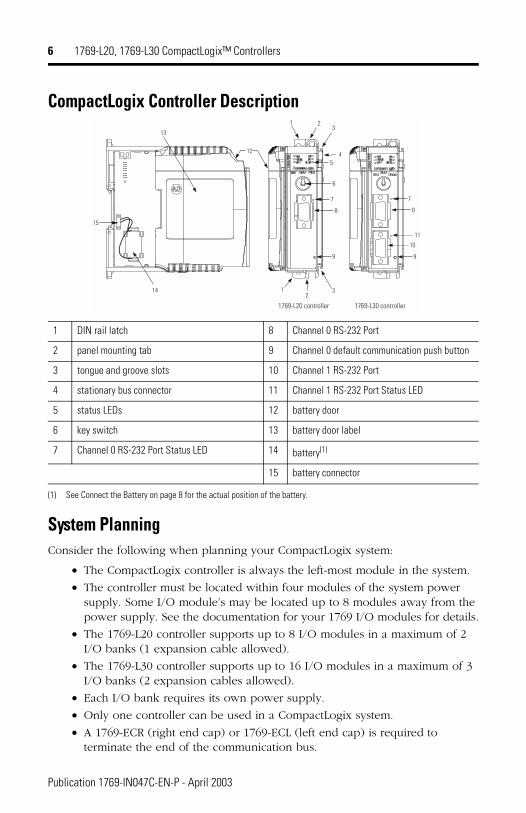
CompactLogix Controller Description
System PlanningConsider the following when planning your CompactLogix system:
� The CompactLogix controller is always the left-most module in the system.
� The controller must be located within four modules of the system power supply. Some I/O module’s may be located up to 8 modules away from the power supply. See the documentation for your 1769 I/O modules for details.
� The 1769-L20 controller supports up to 8 I/O modules in a maximum of 2 I/O banks (1 expansion cable allowed).
� The 1769-L30 controller supports up to 16 I/O modules in a maximum of 3 I/O banks (2 expansion cables allowed).
� Each I/O bank requires its own power supply.
� Only one controller can be used in a CompactLogix system.
� A 1769-ECR (right end cap) or 1769-ECL (left end cap) is required to terminate the end of the communication bus.
1 DIN rail latch 8 Channel 0 RS-232 Port
2 panel mounting tab 9 Channel 0 default communication push button
3 tongue and groove slots 10 Channel 1 RS-232 Port
4 stationary bus connector 11 Channel 1 RS-232 Port Status LED
5 status LEDs 12 battery door
6 key switch 13 battery door label
7 Channel 0 RS-232 Port Status LED 14 battery(1)
(1) See Connect the Battery on page 8 for the actual position of the battery.
15 battery connector
1
1 2
23
3
45
6
7
8
7
8
9 9
10
14
15
12
13
11
1769-L20 controller 1769-L30 controller
Publication 1769-IN047C-EN-P - April 2003
1769-L20, 1769-L30 CompactLogix™ Controllers 7
Install the ControllerThe 1769-L20 and 1769-L30 controllers are suitable for use in an industrial environment when installed in accordance with these instructions. Specifically, this
equipment is intended for use in clean, dry environments (Pollution Degree 2(1))
and with circuits not exceeding Over Voltage Category II(2) (IEC 60664-1).(3)
Prevent Electrostatic Discharge
Remove Power
(1) Pollution Degree 2 is an environment where, normally, only non-conductive pollution occurs except that occasionally a temporary conductivity caused by condensation shall be expected.
(2) Over Voltage Category II is the load level section of the electrical distribution system. At this level transient voltages are controlled and do not exceed the impulse voltage capability of the product’s insulation.
(3) Pollution Degree 2 and Over Voltage Category II are International Electrotechnical Commission (IEC) designations.
ATTENTION
!Electrostatic discharge can damage integrated circuits or semiconductors if you touch bus connector pins. Follow these guidelines when you handle the module:
� Touch a grounded object to discharge static potential.
� Wear an approved wrist-strap grounding device.
� Do not touch the bus connector or connector pins.
� Do not touch circuit components inside the module.
� If available, use a static-safe work station.
� When not in use, keep the module in its static-shield bag.
ATTENTION
!Remove power before removing or inserting this module. When you remove or insert a module with power applied, an electrical arc may occur. An electrical arc can cause personal injury or property damage by:
� sending an erroneous signal to your system’s field devices, causing unintended machine motion
� causing an explosion in a hazardous environment
Electrical arcing causes excessive wear to contacts on both the module and its mating connector. Worn contacts may create electrical resistance.
Publication 1769-IN047C-EN-P - April 2003
8 1769-L20, 1769-L30 CompactLogix™ Controllers
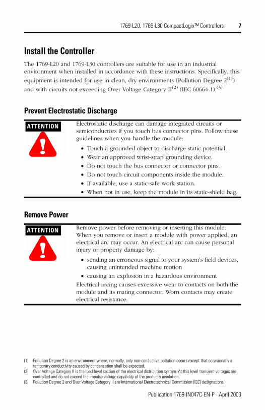
Connect the Battery
The controller is shipped with the battery packed separately. To connect the battery, follow the procedure shown below.
1. Slide the battery door (a) forward.
2. Insert the battery (b) into the battery holder. Insert the battery connector into the connector port (c). The connector is keyed to engage only in the correct polarity.
3. Slide the battery door (a) back until it clicks into position.
For information on battery handling, see page 20.
ATTENTION
!Do not connect or disconnect the battery unless the environment is known to be non-hazardous.
IMPORTANT Do not remove the plastic insulation covering the battery. The insulation is necessary to protect the battery contacts.
b
ac
b
a
c
1769-L20 controller 1769-L30 controller
Publication 1769-IN047C-EN-P - April 2003
1769-L20, 1769-L30 CompactLogix™ Controllers 9
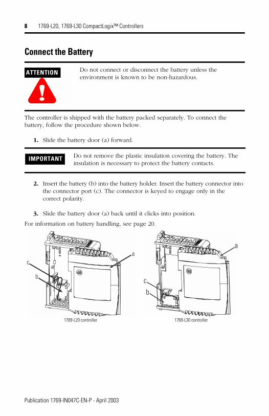
Assemble the SystemThe controller can be attached to an adjacent I/O module or power supply before or after mounting. For mounting instructions, see “Panel Mounting” on page 10, or “DIN Rail Mounting” on page 11.
1. Disconnect line power.
2. Check that the lever of the adjacent module (A) is in the unlocked (fully right) position.
3. Use the upper and lower tongue-and-groove slots (B) to secure the modules together.
4. Move the module back along the tongue-and-groove slots until the bus connectors line up with each other.
5. Use your fingers or a small screwdriver to push the module’s bus lever back slightly to clear the positioning tab (C).
6. Move the module’s bus lever fully to the left (D) until it clicks. Ensure it is locked firmly in place.
7. Attach an end cap terminator (E) to the last module in the system by using the tongue-and-groove slots as before.
8. Lock the end cap bus terminator (F).
ATTENTION
!When attaching the controller, power supply, and I/O modules, it is very important that the bus connectors are securely locked together to ensure proper electrical connection.
FE
D
C
B
B
A
Publication 1769-IN047C-EN-P - April 2003
10 1769-L20, 1769-L30 CompactLogix™ Controllers
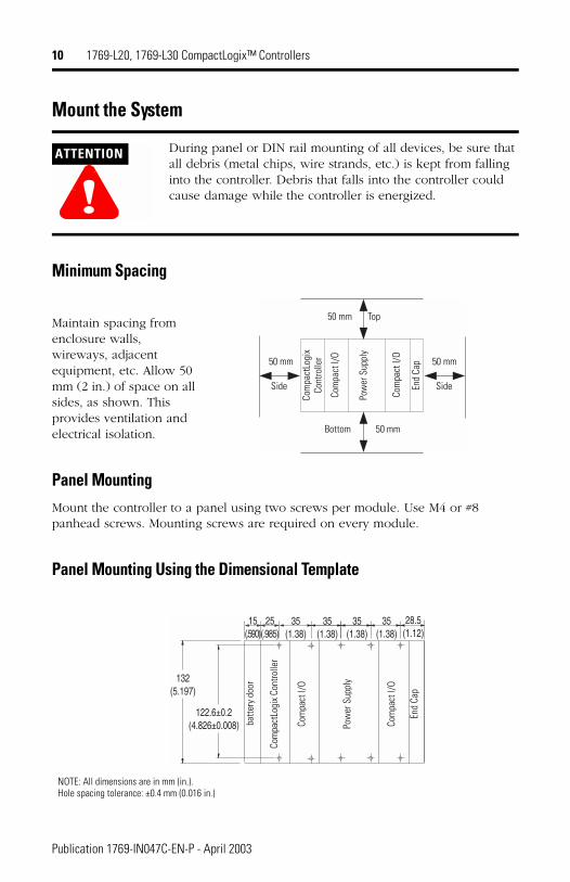
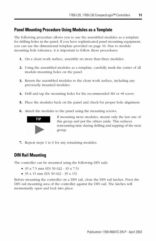
Mount the System
Minimum Spacing
Maintain spacing from enclosure walls, wireways, adjacent equipment, etc. Allow 50 mm (2 in.) of space on all sides, as shown. This provides ventilation and electrical isolation.
Panel MountingMount the controller to a panel using two screws per module. Use M4 or #8 panhead screws. Mounting screws are required on every module.
Panel Mounting Using the Dimensional Template
ATTENTION
!During panel or DIN rail mounting of all devices, be sure that all debris (metal chips, wire strands, etc.) is kept from falling into the controller. Debris that falls into the controller could cause damage while the controller is energized.
Bottom
Side Side
TopCo
mpa
ctLo
gix
Cont
rolle
r
Pow
er S
uppl
y
Com
pact
I/O
Com
pact
I/O
End
Cap
50 mm
50 mm
50 mm
50 mm
35(1.38)
35(1.38)
132(5.197)
122.6±0.2(4.826±0.008)
35(1.38)
28.5(1.12)
25(.985)
15(.590)
35(1.38)
Com
pact
Logi
x Co
ntro
ller
Pow
er S
uppl
y
Com
pact
I/O
Com
pact
I/O
End
Cap
NOTE: All dimensions are in mm (in.).�Hole spacing tolerance: ±0.4 mm (0.016 in.)
batte
ry d
oor
Publication 1769-IN047C-EN-P - April 2003
1769-L20, 1769-L30 CompactLogix™ Controllers 11
Panel Mounting Procedure Using Modules as a TemplateThe following procedure allows you to use the assembled modules as a template for drilling holes in the panel. If you have sophisticated panel mounting equipment, you can use the dimensional template provided on page 10. Due to module mounting hole tolerance, it is important to follow these procedures:
1. On a clean work surface, assemble no more than three modules.
2. Using the assembled modules as a template, carefully mark the center of all module-mounting holes on the panel.
3. Return the assembled modules to the clean work surface, including any previously mounted modules.
4. Drill and tap the mounting holes for the recommended M4 or #8 screw.
5. Place the modules back on the panel and check for proper hole alignment.
6. Attach the modules to the panel using the mounting screws.
7. Repeat steps 1 to 6 for any remaining modules.
DIN Rail MountingThe controller can be mounted using the following DIN rails:
� 35 x 7.5 mm (EN 50 022 - 35 x 7.5)
� 35 x 15 mm (EN 50 022 - 35 x 15)
Before mounting the controller on a DIN rail, close the DIN rail latches. Press the DIN rail mounting area of the controller against the DIN rail. The latches will momentarily open and lock into place.
TIPIf mounting more modules, mount only the last one of this group and put the others aside. This reduces remounting time during drilling and tapping of the next group.
Publication 1769-IN047C-EN-P - April 2003
12 1769-L20, 1769-L30 CompactLogix™ Controllers
Grounding ConsiderationsThis product is intended to be mounted to a well-grounded mounting surface such as a metal panel. Additional grounding connections from the controller’s mounting tabs or DIN rail (if used), are not required unless the mounting surface cannot be grounded. Refer to Industrial Automation Wiring and Grounding Guidelines, Allen-Bradley publication 1770-4.1, for additional information.
Select the Controller’s Operating ModeUse the keyswitch on the front panel of the controller to determine the controller’s operating mode.
Keyswitch Position
Description
RUN � Run the program and enable outputs.� You cannot create or delete tasks, programs, or routines. You cannot create or delete tags
or edit online while the keyswitch is in the RUN position.� You cannot change the mode using the programming software while the keyswitch is in
the RUN position.
PROG � Disable outputs.� Upload projects.� Create, modify, and delete tasks, programs, or routines.� The controller does not execute (scan) tasks while the keyswitch is in the PROG position.� You cannot change the mode through the programming software while the keyswitch is in
the PROG position.
REM Change between Remote Program, Remote Test, and Remote Run modes through the programming software.
Remote Run � The controller executes (scans) tasks.� Enable outputs.� Edit online.
Remote Program � Disable outputs.� Create, modify, and delete tasks, programs or routines.� Download projects.� Edit online.� The controller does not execute (scan) tasks.
Remote Test � Execute tasks with outputs disabled.� Edit online.
Publication 1769-IN047C-EN-P - April 2003
1769-L20, 1769-L30 CompactLogix™ Controllers 13
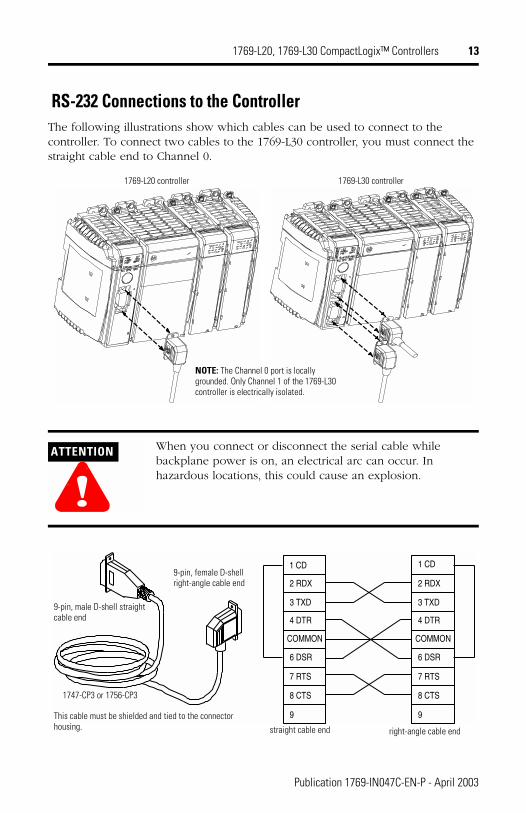
RS-232 Connections to the ControllerThe following illustrations show which cables can be used to connect to the controller. To connect two cables to the 1769-L30 controller, you must connect the straight cable end to Channel 0.
ATTENTION
!When you connect or disconnect the serial cable while backplane power is on, an electrical arc can occur. In hazardous locations, this could cause an explosion.
NOTE: The Channel 0 port is locally grounded. Only Channel 1 of the 1769-L30 controller is electrically isolated.
1769-L20 controller 1769-L30 controller
2 RDX
3 TXD
4 DTR
COMMON
6 DSR
7 RTS
8 CTS
9
1 CD
2 RDX
3 TXD
4 DTR
COMMON
6 DSR
7 RTS
8 CTS
9
1 CD
1747-CP3 or 1756-CP3
9-pin, male D-shell straight cable end
9-pin, female D-shell right-angle cable end
straight cable end right-angle cable end
This cable must be shielded and tied to the connector housing.
Publication 1769-IN047C-EN-P - April 2003
14 1769-L20, 1769-L30 CompactLogix™ Controllers
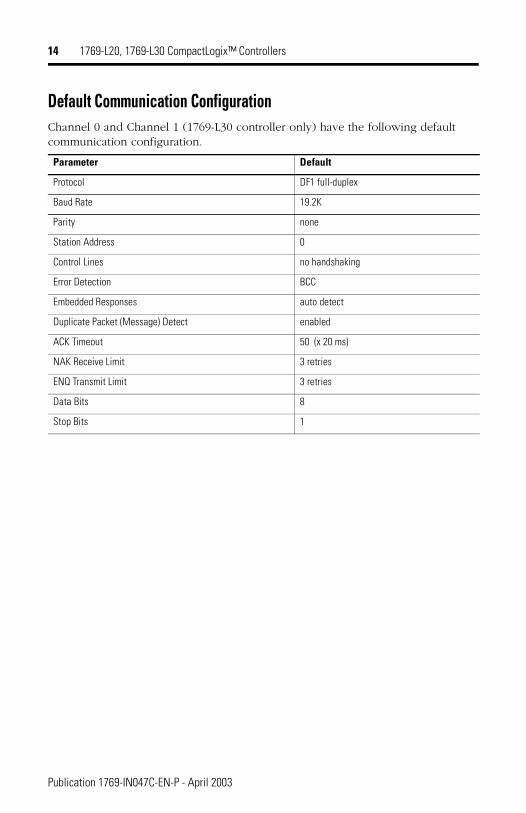
Default Communication ConfigurationChannel 0 and Channel 1 (1769-L30 controller only) have the following default communication configuration.
Parameter Default
Protocol DF1 full-duplex
Baud Rate 19.2K
Parity none
Station Address 0
Control Lines no handshaking
Error Detection BCC
Embedded Responses auto detect
Duplicate Packet (Message) Detect enabled
ACK Timeout 50 (x 20 ms)
NAK Receive Limit 3 retries
ENQ Transmit Limit 3 retries
Data Bits 8
Stop Bits 1
Publication 1769-IN047C-EN-P - April 2003
1769-L20, 1769-L30 CompactLogix™ Controllers 15
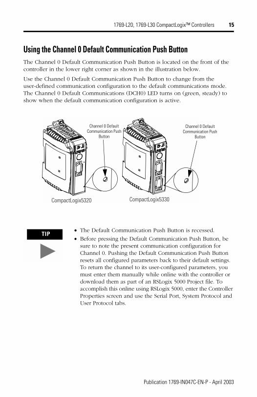
Using the Channel 0 Default Communication Push ButtonThe Channel 0 Default Communication Push Button is located on the front of the controller in the lower right corner as shown in the illustration below.
Use the Channel 0 Default Communication Push Button to change from the user-defined communication configuration to the default communications mode. The Channel 0 Default Communications (DCH0) LED turns on (green, steady) to show when the default communication configuration is active.
TIP� The Default Communication Push Button is recessed.
� Before pressing the Default Communication Push Button, be sure to note the present communication configuration for Channel 0. Pushing the Default Communication Push Button resets all configured parameters back to their default settings. To return the channel to its user-configured parameters, you must enter them manually while online with the controller or download them as part of an RSLogix 5000 Project file. To accomplish this online using RSLogix 5000, enter the Controller Properties screen and use the Serial Port, System Protocol and User Protocol tabs.
CompactLogix5320 CompactLogix5330
Channel 0 Default Communication Push
Button
Channel 0 Default Communication Push
Button
Publication 1769-IN047C-EN-P - April 2003
16 1769-L20, 1769-L30 CompactLogix™ Controllers
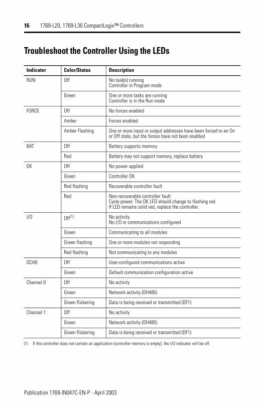
Troubleshoot the Controller Using the LEDs
Indicator Color/Status Description
RUN Off No task(s) running�Controller in Program mode
Green One or more tasks are running�Controller is in the Run mode
FORCE Off No forces enabled
Amber Forces enabled
Amber Flashing One or more input or output addresses have been forced to an On or Off state, but the forces have not been enabled
BAT Off Battery supports memory
Red Battery may not support memory, replace battery
OK Off No power applied
Green Controller OK
Red flashing Recoverable controller fault
Red Non-recoverable controller fault:Cycle power. The OK LED should change to flashing red.�If LED remains solid red, replace the controller.
I/O Off(1)
(1) If the controller does not contain an application (controller memory is empty), the I/O indicator will be off.
No activity�No I/O or communications configured
Green Communicating to all modules
Green flashing One or more modules not responding
Red flashing Not communicating to any modules
DCH0 Off User-configured communications active
Green Default communication configuration active
Channel 0 Off No activity
Green Network activity (DH485)
Green flickering Data is being received or transmitted (DF1)
Channel 1 Off No activity
Green Network activity (DH485)
Green flickering Data is being received or transmitted (DF1)
Publication 1769-IN047C-EN-P - April 2003
1769-L20, 1769-L30 CompactLogix™ Controllers 17
Flash Upgrade the Controller FirmwareTo update the firmware of a controller, first install a firmware upgrade kit.
� An upgrade kit ships on a supplemental CD along with RSLogix 5000 software.
� To download an upgrade kit, go to www.ab.com. Choose Product Support. Choose Firmware Updates.
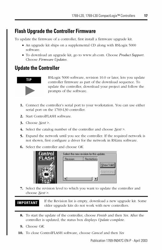
Update the Controller
1. Connect the controller’s serial port to your workstation. You can use either serial port on the 1769-L30 controller.
2. Start ControlFLASH software.
3. Choose Next >.
4. Select the catalog number of the controller and choose Next >.
5. Expand the network until you see the controller. If the required network is not shown, first configure a driver for the network in RSLinx software.
6. Select the controller and choose OK.
7. Select the revision level to which you want to update the controller and choose Next >.
8. To start the update of the controller, choose Finish and then Yes. After the controller is updated, the status box displays Update complete.
9. Choose OK.
10. To close ControlFLASH software, choose Cancel and then Yes
TIPRSLogix 5000 software, revision 10.0 or later, lets you update controller firmware as part of the download sequence. To update the controller, download your project and follow the prompts of the software.
IMPORTANT If the Revision list is empty, download a new upgrade kit. Some older upgrade kits do not work with new controllers.
Publication 1769-IN047C-EN-P - April 2003
18 1769-L20, 1769-L30 CompactLogix™ Controllers
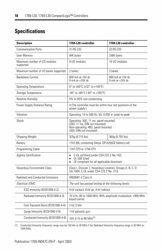
Specifications
Description 1769-L20 controller 1769-L30 controller
Communication Ports (1) RS-232 (2) RS-232
User Memory 64K bytes 256K bytes
Maximum number of I/O modules supported
8 I/O modules 16 I/O modules
Maximum number of I/O banks supported 2 banks 3 banks
Backplane Current 600 mA at +5V dc�0 mA at +24V dc
800 mA at +5V dc�0 mA at +24V dc
Operating Temperature 0° to +60°C (+32° to +140°F)
Storage Temperature -40° to +85°C (-40° to +185°F)
Relative Humidity 5% to 95% non-condensing
Power Supply Distance Rating 4 (The controller must be within four slot positions of the power supply.)
Vibration Operating: 10 to 500 Hz, 5G, 0.030 in. peak-to-peak
Shock Operating: 30G, 11 ms, panel mounted �(20G, 11 ms, DIN rail mounted)Non-operating: 40G, panel mounted�(30G, DIN rail mounted)
Shipping Weight 325g (0.715 lbs) 360g (0.792 lbs)
Battery 1747-BA; containing Sanyo CR14250SE battery cell
Programming Cable 1747-CP3 or 1756-CP3
Agency Certification � C-UL certified (under CSA C22.2 No.142)� UL 508 listed� CE compliant for all applicable directives
Hazardous Environment Class Class I, Division 2, Hazardous Location, Groups A, B, C, D(UL 1604, C-UL under CSA C22.2 No. 213)
Radiated and Conducted Emissions EN50081-2 Class A
Electrical /EMC: The unit has passed testing at the following levels:
ESD Immunity (IEC61000-4-2) 4 kV contact, 8 kV air, 4 kV indirect
Radiated Immunity (IEC61000-4-3) 10 V/m, 80 to 1000 MHz, 80% amplitude modulation, +900 MHz keyed carrier
Fast Transient Burst (IEC61000-4-4) 2 kV, 5 kHz
Surge Immunity (IEC61000-4-5) 1 kV galvanic gun
Conducted Immunity (IEC61000-4-6) 10V, 0.15 to 80 MHz(1)
(1) Conducted Immunity frequency range may be 150 kHz to 30 MHz if the Radiated Immunity frequency range is 30 MHz to 1000 MHz.
Publication 1769-IN047C-EN-P - April 2003
1769-L20, 1769-L30 CompactLogix™ Controllers 19
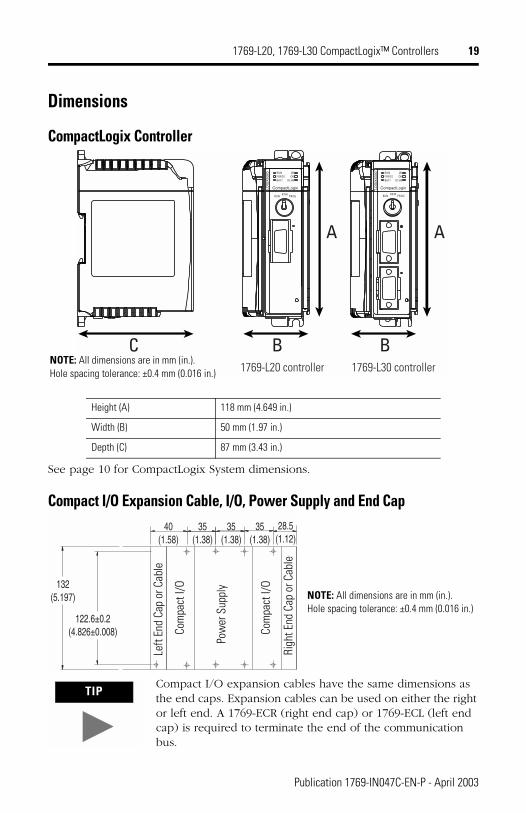
Dimensions
CompactLogix Controller
See page 10 for CompactLogix System dimensions.
Compact I/O Expansion Cable, I/O, Power Supply and End Cap
Height (A) 118 mm (4.649 in.)
Width (B) 50 mm (1.97 in.)
Depth (C) 87 mm (3.43 in.)
TIPCompact I/O expansion cables have the same dimensions as the end caps. Expansion cables can be used on either the right or left end. A 1769-ECR (right end cap) or 1769-ECL (left end cap) is required to terminate the end of the communication bus.
RUNFORCEBATT
I/OOK
DCH0
RUNFORCEBATT
I/OOK
DCH0
REMPROGRUN
CompactLogix CompactLogixLOG
IX53
20
LOG
IX53
30
A
B
A
BC1769-L20 controller 1769-L30 controller
REMPROGRUN
NOTE: All dimensions are in mm (in.).�Hole spacing tolerance: ±0.4 mm (0.016 in.)
35(1.38)
40(1.58)
132(5.197)
122.6±0.2(4.826±0.008)
35(1.38)
28.5(1.12)
35(1.38)
Pow
er S
uppl
y
Righ
t End
Cap
or C
able
Com
pact
I/O
Com
pact
I/O
Left
End
Cap
or C
able
NOTE: All dimensions are in mm (in.).�Hole spacing tolerance: ±0.4 mm (0.016 in.)
Publication 1769-IN047C-EN-P - April 2003
20 1769-L20, 1769-L30 CompactLogix™ Controllers
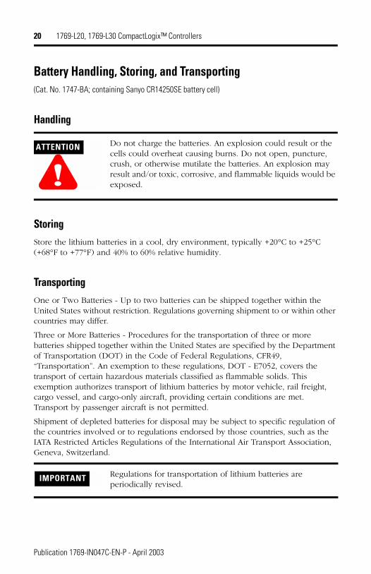
Battery Handling, Storing, and Transporting (Cat. No. 1747-BA; containing Sanyo CR14250SE battery cell)
Handling
StoringStore the lithium batteries in a cool, dry environment, typically +20°C to +25°C (+68°F to +77°F) and 40% to 60% relative humidity.
TransportingOne or Two Batteries - Up to two batteries can be shipped together within the United States without restriction. Regulations governing shipment to or within other countries may differ.
Three or More Batteries - Procedures for the transportation of three or more batteries shipped together within the United States are specified by the Department of Transportation (DOT) in the Code of Federal Regulations, CFR49, “Transportation”. An exemption to these regulations, DOT - E7052, covers the transport of certain hazardous materials classified as flammable solids. This exemption authorizes transport of lithium batteries by motor vehicle, rail freight, cargo vessel, and cargo-only aircraft, providing certain conditions are met. Transport by passenger aircraft is not permitted.
Shipment of depleted batteries for disposal may be subject to specific regulation of the countries involved or to regulations endorsed by those countries, such as the IATA Restricted Articles Regulations of the International Air Transport Association, Geneva, Switzerland.
ATTENTION
!Do not charge the batteries. An explosion could result or the cells could overheat causing burns. Do not open, puncture, crush, or otherwise mutilate the batteries. An explosion may result and/or toxic, corrosive, and flammable liquids would be exposed.
IMPORTANT Regulations for transportation of lithium batteries are periodically revised.
Publication 1769-IN047C-EN-P - April 2003
1769-L20, 1769-L30 CompactLogix™ Controllers 21
For disposal, batteries must be packaged and shipped in accordance with transportation regulations, to a proper disposal site. The U.S. Department of Transportation authorizes shipment of “Lithium batteries for disposal” by motor vehicle only in regulation 173.1015 of CFR 49 (effective January 5, 1983). For additional information contact:
U.S. Department of Transportation�Research and Special Programs Administration�400 Seventh Street, S.W.�Washington, D.C. 20590
Although the Environmental Protection Agency at this time has no regulations specific to lithium batteries, the material contained may be considered toxic, reactive, or corrosive. The person disposing of the material is responsible for any hazard created in doing so. State and local regulations may exist regarding the disposal of these materials.
For a lithium battery material safety data sheet, contact the manufacturer:
Sanyo Energy Corporation�600 Supreme Drive�Bensenville, IL 60106
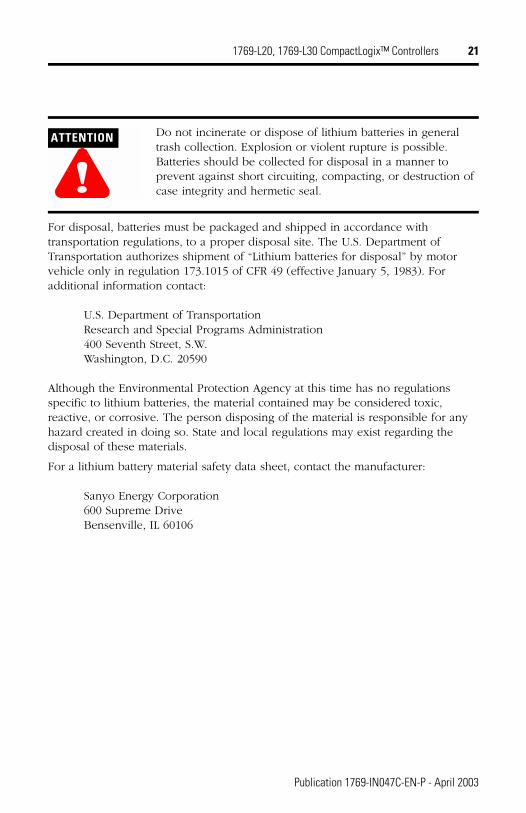
ATTENTION
!Do not incinerate or dispose of lithium batteries in general trash collection. Explosion or violent rupture is possible. Batteries should be collected for disposal in a manner to prevent against short circuiting, compacting, or destruction of case integrity and hermetic seal.
Publication 1769-IN047C-EN-P - April 2003
22 1769-L20, 1769-L30 CompactLogix™ Controllers
Notes:
Publication 1769-IN047C-EN-P - April 2003
1769-L20, 1769-L30 CompactLogix™ Controllers 23
Notes:
Publication 1769-IN047C-EN-P - April 2003
Notes:
CompactLogix and RSLogix 5000 are trademarks of Rockwell Automation.
Publication 1769-IN047C-EN-P - April 2003 PN 957782-12Supersedes Publication 1769-IN047B-EN-P - June 2001 © 2003 Rockwell International Corporation. Printed in the U.S.A.