IntelliDrive SM Update AASHTO SCOHTS Annual Meeting May 1, 2009.
Upload
mark-javierCategory
view
115download
6
Standard Specificationsfor Structural Supports
for Highway Signs,Luminaires, and
Traffic Signals
Fifth Edition 2009

© 2009 by the American Association of State Highway and Transportation Officials. All rights reserved.
Duplication is a violation of applicable law.
ISBN: 978-1-56051-399-5 Publication Code: LTS-5
American Association of State Highway and Transportation Officials
444 North Capitol Street, NW Suite 249 Washington, DC 20001
202-624-5800 phone/202-624-5806 fax www.transportation.org
© 2009 by the American Association of State Highway and Transportation Officials. All rights reserved. Duplication is a violation of applicable law.
© 2009 by the American Association of State Highway and Transportation Officials. All rights reserved.Duplication is a violation of applicable law.

iii
EXECUTIVE COMMITTEE 2007–2008
Voting Members Officers:
President: Allen D. Biehler, Pennsylvania Vice President: Larry L. “Butch” Brown, Mississippi Secretary-Treasurer: Carlos Braceras, Utah
Regional Representatives:
REGION I: Carolann Wicks, Delaware, One-Year Term Joseph Marie, Connecticut, Two-Year Term REGION II: Larry L. “Butch” Brown, Mississippi, One-Year Term Dan Flowers, Arkansas, Two-Year Term REGION III: Kirk T. Steudle Michigan, One-Year Term Nancy J. Richardson, Iowa, Two-Year Term REGION IV: Rhonda G. Faught, New Mexico, One-Year Term Will Kempton, California, Two-Year Term
Nonvoting Members Immediate Past President: Pete K. Rahn, Missouri AASHTO Executive Director: John Horsley, Washington, DC
© 2009 by the American Association of State Highway and Transportation Officials. All rights reserved.Duplication is a violation of applicable law.

iv
HIGHWAYS SUBCOMMITTEE ON BRIDGES AND STRUCTURES, 2008
MALCOLM T. KERLEY, Chair KEVIN THOMPSON, Vice Chair
M. MYINT LWIN, Federal Highway Administration, Secretary FIRAS I. SHEIKH IBRAHIM, Federal Highway Administration, Assistant Secretary
ALABAMA, John F. Black, William F. Conway, George
H. Conner ALASKA, Richard A. Pratt ARIZONA, Jean A. Nehme ARKANSAS, Phil Brand CALIFORNIA, Kevin Thompson, Susan Hida, Barton J.
Newton COLORADO, Mark A. Leonard, Michael G. Salamon CONNECTICUT, Gary J. Abramowicz, Julie F. Georges DELAWARE, Jiten K. Soneji, Barry A. Benton DISTRICT OF COLUMBIA, Nicolas Glados, L. Donald Cooney, Konjit “Connie” Eskender FLORIDA, Robert V. Robertson, Jr., Marcus Ansley, Andre
Pavlov GEORGIA, Paul V. Liles, Jr., Brian Summers HAWAII, Paul T. Santo IDAHO, Matthew M. Farrar ILLINOIS, Ralph E. Anderson, Thomas J. Domagalski INDIANA, Anne M. Rearick IOWA, Norman L. McDonald KANSAS, Kenneth F. Hurst, James J. Brennan, Loren R.
Risch KENTUCKY, Allen Frank LOUISIANA, Hossein Ghara, Arthur D’Andrea, Paul
Fossier MAINE, David Sherlock, Jeffrey S. Folsom MARYLAND, Earle S. Freedman, Robert J. Healy MASSACHUSETTS, Alexander K. Bardow MICHIGAN, Steven P. Beck, David Juntunen MINNESOTA, Daniel L. Dorgan, Kevin Western MISSISSIPPI, Mitchell K. Carr, B. Keith Carr MISSOURI, Dennis Heckman, Michael Harms MONTANA, Kent M. Barnes NEBRASKA, Lyman D. Freemon, Mark Ahlman,
Hussam “Sam” Fallaha NEVADA, Mark P. Elicegui, Marc Grunert, Todd
Stefonowicz NEW HAMPSHIRE, Mark W. Richardson, David L. Scott NEW JERSEY, Richard W. Dunne NEW MEXICO, Jimmy D. Camp NEW YORK, George A. Christian, Donald F. Dwyer,
Arthur P. Yannotti
NORTH CAROLINA, Greg R. Perfetti NORTH DAKOTA, Terrence R. Udland OHIO, Timothy J. Keller, Jawdat Siddiqi OKLAHOMA, Robert J. Rusch, Gregory D. Allen OREGON, Bruce V. Johnson, Hormoz Seradj PENNSYLVANIA, Thomas P. Macioce, Harold C.
“Hal” Rogers, Jr., Lou Ruzzi PUERTO RICO, Jaime Cabré RHODE ISLAND, David Fish SOUTH CAROLINA, Barry W. Bowers, Jeff Sizemore SOUTH DAKOTA, Kevin Goeden TENNESSEE, Edward P. Wasserman TEXAS, William R. Cox, David P. Hohmann U.S. DOT, M. Myint Lwin, Firas I. Sheikh Ibrahim, Hala
Elgaaly UTAH, Richard Miller VERMONT, William Michael Hedges VIRGINIA, Malcolm T. Kerley, Kendal Walus, Prasad
L. Nallapaneni, Julius F. J. Volgyi, Jr. WASHINGTON, Jugesh Kapur, Tony M. Allen, Bijan
Khaleghi WEST VIRGINIA, Gregory Bailey WISCONSIN, Scot Becker, Beth A. Cannestra, Finn
Hubbard WYOMING, Gregg C. Fredrick, Keith R. Fulton ALBERTA, Tom Loo NEW BRUNSWICK, Doug Noble NOVA SCOTIA, Mark Pertus ONTARIO, Bala Tharmabala SASKATCHEWAN, Howard Yea GOLDEN GATE BRIDGE, Kary H. Witt N.J. TURNPIKE AUTHORITY, Richard J. Raczynski N.Y. STATE BRIDGE AUTHORITY, William J. Moreau PENN. TURNPIKE COMMISSION, Gary L. Graham SURFACE DEPLOYMENT AND DISTRIBUTION
COMMAND TRANSPORTATION ENGINEERING AGENCY, Robert D. Franz
U.S. ARMY CORPS OF ENGINEERS—DEPARTMENT OF THE ARMY, Paul C. T. Tan
U.S. COAST GUARD, Nick E. Mpras, Jacob Patnaik U.S. DEPARTMENT OF AGRICULTURE—
FOREST SERVICE, John R. Kattell
© 2009 by the American Association of State Highway and Transportation Officials. All rights reserved.
Duplication is a violation of applicable law.

v
FOREWORD
The fifth edition of the Standard Specifications for Structural Supports for Highway Signs, Luminaires, and Traffic Signals incorporates recent work performed under the National Cooperative Highway Research Program (NCHRP) and state-sponsored research activities. NCHRP 20-07 Task 209 reviewed past research and recommended updates to the Specifications. Changes are primarily a result of NCHRP Report 469: Fatigue-Resistant Design of Cantilevered Signal, Sign, and Light Supports, and NCHRP Report 494: Structural Supports for Highway Signs, Luminaires and Traffic Signals.
Section 3, “Loads,” includes a metric conversion of the wind map presented in ASCE/SEI 7-05. The basic wind speed
map is updated based on a new analysis of hurricane wind speeds and more detailed maps are included for hurricane-prone regions. Drag coefficients for multisided shapes are included which utilize a linear transition from a round to a multisided cross section.
Design guidelines for bending about the diagonal axis for rectangular steel sections are included in Section 5, “Steel
Design.” The width-to-thickness ratios and the non-compact limit for stems of tees are also specified. Guidance is provided on the selection of base plate thickness because thicker base plates can dramatically increase fatigue life of the pole to base plate connection. Section 5 also includes updates to the anchor bolt material specifications used in traffic signal support structures; the design loads of double-nut and single-nut anchor bolt connections; allowable stresses in anchor bolts; specifications to proportion anchor bolt holes in the base plate; and guidance on anchor bolt tightening.
The scope of Section 11, “Fatigue Design,” is expanded to include non-cantilevered support structures and the
associated fatigue importance factors. Vortex shedding response has been observed in tapered lighting poles often exciting second or third mode vibrations. Tapered poles are now required to be investigated for vortex shedding. Drag coefficients to be used in the calculation of vortex shedding, natural wind gusts, and truck induced wind gusts have been clarified, and additional guidance is provided as commentary for the selection of the fatigue importance category. Finally, the influence of unequal leg fillet welds on the fatigue performance has been included.
The Specifications are based on the allowable stress design methodology and are intended to address the usual
structural supports. Requirements more stringent than those in the Specifications may be appropriate for atypical structural supports. The commentary is intended to provide background on some of the considerations contained in the Specifications; however it does not provide a complete historical background nor detailed discussions of the associated research studies. The Specifications and accompanying commentary do not replace sound engineering knowledge and judgment.
AASHTO Highways Subcommittee on Bridges and Structures
© 2009 by the American Association of State Highway and Transportation Officials. All rights reserved.Duplication is a violation of applicable law.

vi
PREFACE
The fifth edition of Standard Specifications for Structural Supports for Highway Signs, Luminaires, and Traffic Signals supersedes the fourth edition and its 2002, 2003, and 2006 interims. It includes changes approved by the Highways Subcommittee on Bridges and Structures in 2007 and 2008.
An abbreviated table of contents follows this preface. Detailed tables of contents precede each Section and each
Appendix. For the first time, Standard Specifications for Structural Supports for Highway Signs, Luminaires, and Traffic Signals
includes a CD-ROM with many helpful search features that will be familiar to users of the AASHTO LRFD Bridge Design Specifications CD-ROM. Examples include:
• Bookmarks to all articles;
• Links within the text to cited articles, figures, tables, and equations;
• Links for current titles in reference lists to AASHTO’s Bookstore; and
• The Acrobat search function.
AASHTO Publications Staff
© 2009 by the American Association of State Highway and Transportation Officials. All rights reserved.Duplication is a violation of applicable law.

vii
ABBREVIATED TABLE OF CONTENTS
SECTION 1: INTRODUCTION..........................................................................................................................................1-i
SECTION 2: GENERAL FEATURES OF DESIGN ..........................................................................................................2-i
SECTION 3: LOADS ..........................................................................................................................................................3-i
SECTION 4: ANALYSIS AND DESIGN—GENERAL CONSIDERATIONS.................................................................4-i
SECTION 5: STEEL DESIGN ............................................................................................................................................5-i
SECTION 6: ALUMINUM DESIGN..................................................................................................................................6-i
SECTION 7: PRESTRESSED CONCRETE DESIGN .......................................................................................................7-i
SECTION 8: FIBER-REINFORCED COMPOSITES DESIGN.........................................................................................8-i
SECTION 9: WOOD DESIGN............................................................................................................................................9-i
SECTION 10: SERVICEABILITY REQUIREMENTS....................................................................................................10-i
SECTION 11: FATIGUE DESIGN ...................................................................................................................................11-i
SECTION 12: BREAKAWAY SUPPORTS .....................................................................................................................12-i
SECTION 13: FOUNDATION DESIGN..........................................................................................................................13-i
APPENDIX A: ANALYSIS OF SPAN-WIRE STRUCTURES ........................................................................................A-i
APPENDIX B: DESIGN AIDS ..........................................................................................................................................B-i
APPENDIX C: ALTERNATE METHOD FOR WIND PRESSURES ..............................................................................C-i
© 2009 by the American Association of State Highway and Transportation Officials. All rights reserved.Duplication is a violation of applicable law.

1-i
SECTION 1: INTRODUCTION
TABLE OF CONTENTS 1 1 1.1—SCOPE..........................................................................................................................................................................1-1
1.2—DEFINITIONS .............................................................................................................................................................1-2
1.3—APPLICABLE SPECIFICATIONS ............................................................................................................................1-2
1.4—TYPES OF STRUCTURAL SUPPORTS...................................................................................................................1-3 1.4.1—Sign.....................................................................................................................................................................1-3 1.4.2—Luminaire ...........................................................................................................................................................1-3 1.4.3—Traffic Signal......................................................................................................................................................1-6 1.4.4—Combination Structures .....................................................................................................................................1-6
1.5—REFERENCES.............................................................................................................................................................1-8
© 2009 by the American Association of State Highway and Transportation Officials. All rights reserved.Duplication is a violation of applicable law.

1-1
SECTION 1: INTRODUCTION
1.1—SCOPE
C1.1
The provisions of these Standard Specifications for Structural Supports for Highway Signs, Luminaires, andTraffic Signals, hereinafter referred to as the Specifications,are applicable to the structural design of supports forhighway signs, luminaires, and traffic signals. The types ofsupports covered in these Specifications are discussed in Article 1.4. The Specifications are intended to serve as astandard and guide for the design, fabrication, and erection ofthese types of supports.
These Specifications are the result of National Cooperative Highway Research Program (NCHRP) Project 17-10 and the corresponding NCHRP Report 411. At the discretion of the Owner, proprietary solutions may be considered. These solutions may address both new structures and the repair or rehabilitation of existing structures. Testing of proprietary solutions shall model actual conditions as closely as possible, and the test methods and results shall be published. These Specifications are intended to replace the previous edition, Standard Specifications for Structural Supports for Highway Signs, Luminaires, and Traffic Signals (2001).
These Specifications are not intended to supplant
proper training or the exercise of judgment by the designer,and they include only the minimum requirements necessaryto provide for public safety. The Owner or the designer mayrequire the design and quality of materials and constructionto be higher than the minimum requirements.
The commentary directs attention to other documentsthat provide suggestions for carrying out the requirementsand intent of these Specifications. However, those documentsand the commentary are not intended to be a part of theSpecifications.
The commentary discusses some provisions of the Specifications with emphasis given to the explanation of new or revised provisions that may be unfamiliar to users of the Specifications. The commentary is not intended to provide a complete historical background concerning the development of this and previous Specifications, nor is it intended to provide a detailed summary of the studies and research data reviewed in formulating the provisions of the Specifications. However, references to some of the research data are provided for those who wish to study the background material in depth.
© 2009 by the American Association of State Highway and Transportation Officials. All rights reserved.Duplication is a violation of applicable law.

1-2 STANDARD SPECIFICATIONS FOR STRUCTURAL SUPPORTS FOR HIGHWAY SIGNS, LUMINAIRES, AND TRAFFIC SIGNALS
1.2—DEFINITIONS
Arm—A cantilevered support, either horizontal or sloped.
Bridge Support—Also known as span-type support; a horizontal or sloped member or truss supported by at least two verticalsupports.
Cantilever—A support, either horizontal or vertical, supported at one end only.
Designer—The person responsible for design of the structural support.
High-Level Lighting—Also known as high-mast lighting; lighting provided at heights greater than about 17 m (55 ft), typically using four to twelve luminaires.
Luminaire—A complete lighting unit consisting of a lamp or lamps together with the parts designed to distribute the light, toposition and protect the lamps, and to connect the lamps to the electric power supply.
Mast Arm—A supporting arm designed to hold a sign, signal head, or luminaire in an approximately horizontal position.
Monotube—A support that is composed of a single tube.
Overhead Sign—A sign suspended above the roadway.
Owner—The person or agency having jurisdiction for the design, construction, and maintenance of the structural support.
Pole—A vertical support that is long, relatively slender, and generally rounded or multisided.
Pole Top—A descriptive term indicating that an attachment is mounted at the top of a structural support, usually pertaining to one luminaire or traffic signal mounted at the top of a pole.
Roadside Sign—A sign mounted beside the roadway on a single support or multiple supports.
Sign—A device conveying a specific message by means of words or symbols, erected for the purpose of regulating, warning,or guiding traffic.
Span Wire—A steel cable or strand extended between two poles, commonly used as a horizontal support for small signs andtraffic signals.
Structural Support—Support designed to carry the loads induced by attached signs, luminaires, and traffic signals.
Traffic Signal—An electrically operated traffic control device by which traffic is regulated, warned, or directed to take specific actions.
Truss—A structural support, usually vertical or horizontal, composed of framework that is often arranged in triangles.
1.3—APPLICABLE SPECIFICATIONS
The following specification documents may bereferenced for additional information on design, materials,fabrication, and construction:
• Standard Specifications for Highway Bridges,
• AASHTO LRFD Bridge Design Specifications,
• Standard Specifications for Transportation Materialsand Methods of Sampling and Testing, and
• Book of ASTM Standards.
© 2009 by the American Association of State Highway and Transportation Officials. All rights reserved.Duplication is a violation of applicable law.

SECTION 1: INTRODUCTION 1-3
1.4—TYPES OF STRUCTURAL SUPPORTS
Structural supports are categorized as follows:
• Sign support structures,
• Luminaire support structures,
• Traffic signal support structures, and
• A combination of these structures.
1.4.1—Sign
C1.4.1
Structural supports for signs include both overhead and roadside sign structures that are intended to support highwaytraffic signs and markers.
Typical overhead and roadside sign supports are shown in Figure 1-1. Overhead sign structures are generally of the bridge or cantilever type. It is also common to support signs on existing grade separation structures that span the traffic lanes.
1.4.2—Luminaire
C1.4.2
Structural supports for luminaires include typicallighting poles, pole top-mounted luminaire poles, and high-level poles.
The lighting of modern freeways includes the use of typical lighting poles, generally tubular pole shafts that support one to two luminaires and range in height from about 9 m (30 ft) to 17 m (55 ft). High-level lighting poles are normally in heights from about 17 m (55 ft) to 46 m (150 ft) or more, usually supporting 4 to 12 luminaires; they are used to illuminate large areas. Typical luminaire supports and high-level supports are shown in Figure 1-2.
© 2009 by the American Association of State Highway and Transportation Officials. All rights reserved.Duplication is a violation of applicable law.

1-4 STANDARD SPECIFICATIONS FOR STRUCTURAL SUPPORTS FOR HIGHWAY SIGNS, LUMINAIRES, AND TRAFFIC SIGNALS
Figure 1-1—Sign Supports
© 2009 by the American Association of State Highway and Transportation Officials. All rights reserved.Duplication is a violation of applicable law.

SECTION 1: INTRODUCTION 1-5
Figure 1-2—Luminaire Structural Supports
© 2009 by the American Association of State Highway and Transportation Officials. All rights reserved.Duplication is a violation of applicable law.

1-6 STANDARD SPECIFICATIONS FOR STRUCTURAL SUPPORTS FOR HIGHWAY SIGNS, LUMINAIRES, AND TRAFFIC SIGNALS
1.4.3—Traffic Signal
C1.4.3
Structural supports for mounting traffic signals includepole top, cantilevered arms, bridge, and span wires.
Typical traffic signal supports are shown in Figure 1-3.
1.4.4—Combination Structures
C1.4.4
Combination structures include structural supports thatcombine any of the functions described in Articles 1.4.1,1.4.2, and 1.4.3.
Generally, combination structures are composed of a luminaire support and a traffic signal support. Other structures may combine traffic signal or luminaire supports with those for utility lines.
© 2009 by the American Association of State Highway and Transportation Officials. All rights reserved.Duplication is a violation of applicable law.

SECTION 1: INTRODUCTION 1-7
Figure 1-3—Traffic Signal Structural Supports
© 2009 by the American Association of State Highway and Transportation Officials. All rights reserved.Duplication is a violation of applicable law.

1-8 STANDARD SPECIFICATIONS FOR STRUCTURAL SUPPORTS FOR HIGHWAY SIGNS, LUMINAIRES, AND TRAFFIC SIGNALS
1.5—REFERENCES
AASHTO. 1968. AASHTO Highway Definitions. American Association of State Highway and Transportation Officials,Washington, DC.
AASHTO. 2001. Standard Specifications for Structural Supports for Highway Signs, Luminaires and Traffic Signals, Fourth Edition, LTS-4. American Association of State Highway and Transportation Officials. Washington, DC.
AASHTO. 2002. AASHTO Standard Specifications for Highway Bridges, 17th Edition, HB-17. American Association of State Highway and Transportation Officials, Washington, DC.
AASHTO. 2007. AASHTO LRFD Bridge Design Specifications, Fourth Edition, LRFDUS-4-M and LRFDSI-4. American Association of State Highway and Transportation Officials, Washington, DC.
AASHTO. 2008. Standard Specifications for Transportation Materials and Methods of Sampling and Testing. 28th Edition, HM-28. American Association of State Highway and Transportation Officials, Washington, DC.
ASTM. 2001. Book of ASTM Standards. American Society for Testing and Materials, West Conshohocken, PA.
Fouad, F. H., E. A. Calvert, and E. Nunez. 1998. Structural Supports for Highway Signs, Luminaires, and Traffic Signals, NCHRP Report 411. Transportation Research Board, National Research Council, Washington, DC.
© 2009 by the American Association of State Highway and Transportation Officials. All rights reserved.Duplication is a violation of applicable law.

2-i
SECTION 2: GENERAL FEATURES OF DESIGN
TABLE OF CONTENTS
2 2.1—SCOPE.............................................................................................................................................................................. 2-1
2.2—DEFINITIONS ................................................................................................................................................................. 2-1
2.3—AESTHETICS .................................................................................................................................................................. 2-2
2.4—FUNCTIONAL REQUIREMENTS................................................................................................................................ 2-2 2.4.1—Lighting Systems.................................................................................................................................................... 2-2
2.4.1.1—Vertical Heights for Luminaire Supports.................................................................................................... 2-2 2.4.1.2—Illumination of the Roadway....................................................................................................................... 2-3
2.4.2—Structural Supports for Signs and Traffic Signals................................................................................................. 2-3 2.4.2.1—Vertical Clearances...................................................................................................................................... 2-3 2.4.2.2—Size, Height, and Location of Signs............................................................................................................ 2-5 2.4.2.3—Illumination and Reflectorization of Signs................................................................................................. 2-5 2.4.2.4—Variable Message Signs .............................................................................................................................. 2-5
2.5—ROADSIDE REQUIREMENTS FOR STRUCTURAL SUPPORTS .......................................................................... 2-5 2.5.1—Clear Zone Distance............................................................................................................................................... 2-6 2.5.2—Breakaway Supports .............................................................................................................................................. 2-6
2.5.2.1—Foundations ................................................................................................................................................. 2-6 2.5.2.2—Impact Height .............................................................................................................................................. 2-6
2.5.3—Guardrails and Other Barriers................................................................................................................................ 2-7 2.5.4—Roadside Sign and Luminaire Supports ................................................................................................................ 2-7 2.5.5—Overhead Sign Supports and High-Level Lighting Supports ............................................................................... 2-7 2.5.6—Traffic Signal Supports .......................................................................................................................................... 2-7 2.5.7—Gores....................................................................................................................................................................... 2-7 2.5.8—Urban Areas............................................................................................................................................................ 2-8 2.5.9—Joint-Use Supports ................................................................................................................................................. 2-8
2.6—CORRELATION OF STRUCTURAL SUPPORT DESIGN WITH ROADWAY AND BRIDGE DESIGN........... 2-8 2.6.1—Signs ....................................................................................................................................................................... 2-8 2.6.2—Luminaires.............................................................................................................................................................. 2-8
2.7—MAINTENANCE............................................................................................................................................................. 2-8
2.8—REFERENCES................................................................................................................................................................. 2-9
© 2009 by the American Association of State Highway and Transportation Officials. All rights reserved.Duplication is a violation of applicable law.

2-1
SECTION 2:
GENERAL FEATURES OF DESIGN
2.1—SCOPE
C2.1
Minimum requirements are provided or referenced for aesthetics, clearances, constructibility, inspectability, andmaintainability of structural supports. Guidelines fordetermining vertical and lateral clearances, use of breakawaysupports, use of guardrails, illumination of the roadway, sizesof signs, illumination and reflectorization of signs, andmaintenance are found in the following references:
• A Policy on Geometric Design of Highways and Streets,
• Manual on Uniform Traffic Control Devices,
• Roadside Design Guide,
• AASHTO Maintenance Manual for Roadways andBridges, and
• Roadway Lighting Design Guide.
This Section is intended to provide the Designer with information and references to determine the configuration, overall dimensions, and location of structural supports for highway signs, luminaires, and traffic signals. The material in this Section is broad in nature. No attempt has been made to establish rigid criteria in such areas as vertical heights of traffic signal and luminaire supports and levels of illumination. This Section provides references and considerations for the different aspects of design that should be considered in the preliminary stages of a project. In addition to the requirements provided within this Section, many Owners have their own requirements.
2.2—DEFINITIONS
Barrier—A longitudinal traffic barrier, usually rigid, used to shield roadside obstacles or nontraversable terrain features. It may occasionally be used to protect pedestrians from vehicle traffic.
Breakaway—A design feature that allows a sign, luminaire, or pole top–mounted traffic signal support to yield, fracture, or separate near ground level on impact.
Clear Zone—The total roadside border area, starting at the edge of the traveled way, available for unobstructed use by errant vehicles.
Clearance—Horizontal or vertical dimension to an obstruction.
Curb—A vertical or sloping surface, generally along and defining the edge of a roadway or roadway shoulder.
Gore—The center area immediately past the point where two roadways divide at an acute angle, usually where a ramp leaves aroadway.
Guardrail—A type of longitudinal traffic barrier, usually flexible.
Mounting Height—Minimum vertical distance to the bottom of a sign or traffic signal, or to the center of gravity of a luminaire, relative to the pavement surface.
Pedestal Pole—A relatively short pole supporting a traffic signal head attached directly to the pole.
Roadside—The area between the shoulder edge and the right-of-way limits, or the area between roadways of a divided highway.
© 2009 by the American Association of State Highway and Transportation Officials. All rights reserved.Duplication is a violation of applicable law.

2-2 STANDARD SPECIFICATIONS FOR STRUCTURAL SUPPORTS FOR HIGHWAY SIGNS, LUMINAIRES, AND TRAFFIC SIGNALS
2.3—AESTHETICS
C2.3
The structural support should complement itssurroundings, be graceful yet functional in form, and presentan appearance of adequate strength. The support should have apleasing appearance that is consistent with the aesthetic effectof the highway’s other physical features. Supports should haveclean, simple lines, which will present minimum hazard tomotorists.
Structural supports should be designed and located so asnot to distract the motorist’s attention or obstruct the view ofthe highway. Supports should be placed so they do notobstruct the view of other signs or important roadway features. The effect that signing or lighting installations have on thesurrounding environment should be evaluated.
The appearance of ordinary structural supports should consider aesthetics and function. Combination poles, which serve multiple functions for lighting, traffic control, and electrical power, should be taken under consideration to reduce the number of different poles along the highway.
2.4—FUNCTIONAL REQUIREMENTS
2.4.1—Lighting Systems
C2.4.1
General guidelines concerning lighting systems for highways may be found in An Informational Guide forRoadway Lighting.
The Designer should select the light source, luminaire distribution, mounting height, and luminaire overhang based on such factors as geometry and character of the roadway, environment, proposed maintenance, economics, aesthetics, and overall lighting objectives. Some communities limit the amount of surrounding glare from illumination systems, and shielding may be required. The same average level of lighting can usually be obtained by more than one installation arrangement. An Informational Guide for Roadway Lightingprovides information on level and uniformity of illuminance and luminance, quality of light, location of poles, use of breakaway devices, high-mast poles, and maintenance. Additional information may also be found in A Study of Roadway Lighting. Additional information on breakaway devices for lighting poles may be found in the Roadside Design Guide.
2.4.1.1—Vertical Heights for Luminaire Supports
C2.4.1.1
The height of the luminaire support should be determinedby the Designer to fit the particular need and situation.
Some items that should be considered by the Designer in determining the height of a luminaire support are as follows:
• Glare characteristics of the highway,
• Desired level of illumination and distribution of light over the roadway area,
• Photometric characteristics of a selected lamp and luminaire,
• Available space for placing the supports, and
• Maintenance capability (maximum attainable servicing height).
Height restrictions may be imposed by various government agencies, such as the Federal Highway Administration (FHWA) with respect to breakaway devices and the Federal Aviation Administration for aircraft considerations.
© 2009 by the American Association of State Highway and Transportation Officials. All rights reserved.Duplication is a violation of applicable law.

SECTION 2: GENERAL FEATURES OF DESIGN 2-3
2.4.1.2—Illumination of the Roadway
C2.4.1.2
The Designer should consider the quality of light and thelevel of illumination for a roadway lighting system.
Highway illumination is provided to improve driver nighttime visibility and to promote safer and more efficient use of special roadway facilities located at ramps, intersections, and potentially hazardous areas.
The amount of illumination that should be provided over a roadway depends on the interaction among visibility, visual comfort, light distribution, and the geometry of the lighting system. Disability and discomfort glare, pavement glare, road location, and obstructions to visibility and traffic patterns are other factors that influence the level of illumination to beprovided by a lighting system.
A luminaire installation should provide a visual environment that is conducive to safe and comfortable night driving. Where pedestrian safety is not involved, there is no indication that the lighting of bridges and overpasses should be any different from elsewhere on the highway.
2.4.2—Structural Supports for Signs and Traffic Signals
2.4.2.1—Vertical Clearances
C2.4.2.1
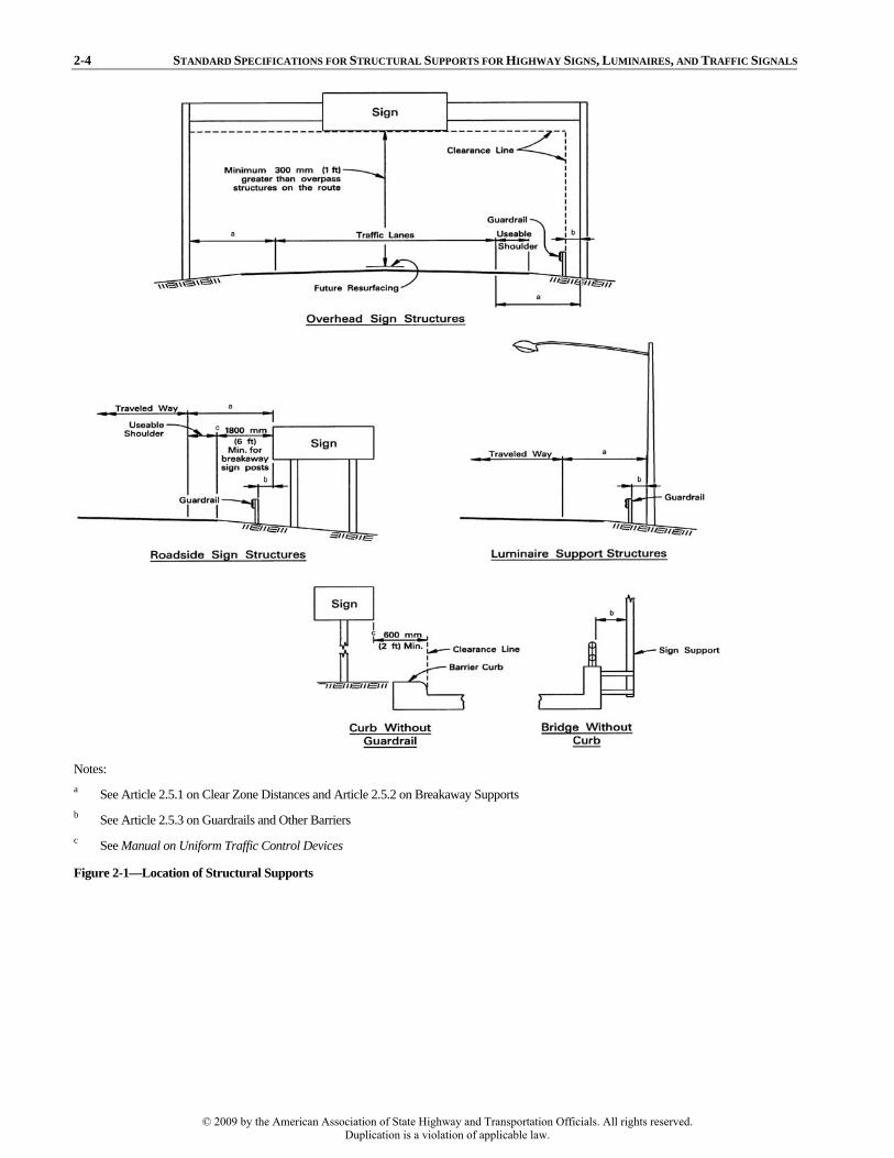
Overhead sign and overhead traffic signal structures shallprovide a vertical clearance over the entire width of thepavement and shoulders of 300 mm (1 ft) greater than therequired minimum vertical clearance of overpass structures onthe route. The vertical clearance shall be either in conformancewith A Policy on Geometric Design of Highways and Streetsfor the functional classification of the highway, or exceptionsthereto shall be justified. Possible reduction of verticalclearance should be investigated. Additional guidance onvertical clearances may be found in the Manual on UniformTraffic Control Devices.
The minimum clearance should include an allowance for possible future overlays.
The additional 300-mm (1-ft) vertical clearance is required so that high vehicles will strike the stronger overpass structures first, thereby lessening the chance of major collision damage to the structurally weaker overhead sign support or traffic signal support structures. A depiction of this clearance limit is illustrated in Figure 2-1.
© 2009 by the American Association of State Highway and Transportation Officials. All rights reserved.Duplication is a violation of applicable law.
2-4 STANDARD SPECIFICATIONS FOR STRUCTURAL SUPPORTS FOR HIGHWAY SIGNS, LUMINAIRES, AND TRAFFIC SIGNALS
Notes: a See Article 2.5.1 on Clear Zone Distances and Article 2.5.2 on Breakaway Supports b See Article 2.5.3 on Guardrails and Other Barriers c See Manual on Uniform Traffic Control Devices
Figure 2-1—Location of Structural Supports
© 2009 by the American Association of State Highway and Transportation Officials. All rights reserved.Duplication is a violation of applicable law.
SECTION 2: GENERAL FEATURES OF DESIGN 2-5
2.4.2.2—Size, Height, and Location of Signs
C2.4.2.2
The Manual on Uniform Traffic Control Devices should be consulted for the sizes, heights, and placement of signs forany installation.
The Manual on Uniform Traffic Control Devices includes information on signs for sizes, illumination and reflectorization, location, height, and lateral clearance.
2.4.2.3—Illumination and Reflectorization of Signs
C2.4.2.3
Illumination and reflectorization of signs should conformwith the provisions of the Manual on Uniform Traffic ControlDevices.
An Informational Guide for Roadway Lighting provides some information for luminance and illuminance of signs.
Except where reflectorization is deemed adequate, alloverhead sign installations should normally be illuminated.The lighting equipment should produce uniform illuminationfor the sign surface and the position of the lighting fixtures should not impair normal viewing of the sign or obstruct viewof the roadway. Where internal illumination is used inconjunction with translucent materials, the colors of the signshould appear essentially the same by night and day.
High-intensity reflectorized sheeting can be used to eliminate the need for sign illumination and maintenance walkways.
2.4.2.4—Variable Message Signs
C2.4.2.4
Cantilevered support structures for variable message signs(VMS) shall be designed for fatigue in accordance with Section 11, “Fatigue Design.”
The design of VMS support structures, enclosures, and connections to the support structure will normally requireadditional considerations that are beyond the scope of theseSpecifications.
VMS are composed of lamps or luminous elements that may be visible during the day as well as at night. The lamps and electronics are contained within an enclosure, which weighs significantly more than most sign panels.
NCHRP Report 411 provides some information regarding the design of VMS support structures. Additional design considerations that are not provided in the report may still be required.
2.5—ROADSIDE REQUIREMENTS FOR STRUCTURAL SUPPORTS
C2.5
Consideration shall be given to safe passage of vehiclesadjacent to or under a structural support. The hazard to errantvehicles within the clear zone distance, defined in Article2.5.1, should be minimized by locating obstacles a safedistance away from the travel lanes. Roadside requirementsand location of structural supports for highway signs,luminaires, and traffic signals should generally adhere to theprinciples given in Articles 2.5.1 through 2.5.9.
Where possible, a single support should be used for dual purposes (e.g., signals and lighting). Consideration should also be given to locating luminaire supports to minimize the necessity of encroaching on the traveled way during routine maintenance.
© 2009 by the American Association of State Highway and Transportation Officials. All rights reserved.Duplication is a violation of applicable law.

2-6 STANDARD SPECIFICATIONS FOR STRUCTURAL SUPPORTS FOR HIGHWAY SIGNS, LUMINAIRES, AND TRAFFIC SIGNALS
2.5.1—Clear Zone Distance
C2.5.1
Structural supports should be located in conformance withthe clear zone concept as contained in Chapter 3, “RoadsideTopography and Drainage Features,” of the Roadside DesignGuide, or other clear zone policy accepted by the FHWA.Where the practical limits of structure costs, type of structures,volume and design speed of through-traffic, and structurearrangement make conformance with the Roadside Design Guide impractical, the structural support should be providedwith a breakaway device or protected by the use of a guardrailor other barrier.
The clear zone, illustrated in Figure 2-1, is the roadside border area beyond the traveled way, available for safe use by errant vehicles. This area may consist of a shoulder, a recoverable slope, a nonrecoverable slope, and/or a clear run-out area. The desired width is dependent on the traffic volumes and speeds and on the roadside geometry.
Suggested minimum clear zone distances are provided in the Roadside Design Guide and are dependent on average daily traffic, slope of roadside, and design vehicle speed. Additional discussions of clear zone distances and lateral placement of structural support may be found in the Manual on Uniform Traffic Control Devices and A Policy on Geometric Design of Highways and Streets.
2.5.2—Breakaway Supports
C2.5.2
Breakaway supports should be used for luminaire and roadside sign supports when they cannot be placed outside theroadside clear zone or behind a guardrail. The requirements ofSection 12, “Breakaway Supports,” shall be satisfied. Therequirements of Articles 2.5.2.1 and 2.5.2.2 should be met forthe proper performance of the breakaway support.
Breakaway supports housing electrical components shallhave the use of electrical disconnects considered for all newinstallations and for existing installations that experiencefrequent knockdown.
Generally, breakaway supports should be provided whenever the support is exposed to traffic. Breakaway supports cannot usually be incorporated with overhead sign bridges, cantilever overhead signs, or high-level lighting supports. These structure types can often be placed outside the clear zone; however, if they are located within the clear zone, barrier protection is required.
Article 12.5.3 contains information on electrical disconnects.
2.5.2.1—Foundations
C2.5.2.1
The top of foundations and projections of any rigidlyattached anchor bolts or anchor supports should not extendabove the ground level enough to increase the hazard or tointerfere with the operation of a breakaway support.
Foundations for breakaway supports located on slopes are likely to require special details to avoid creating a notch in the slope that could impede movement of the support when broken away or a projection of the foundation that could snag the undercarriage of an impacting vehicle. Foundations should be designed considering the breakaway stub height limitations of Article 12.5.3.
2.5.2.2—Impact Height
C2.5.2.2
Breakaway supports should be located such that thelocation of impact of an errant vehicle’s bumper is consistentwith the maximum bumper height used in breakaway qualification tests.
The breakaway performance of most, if not all, breakaway supports degrades with an increase in impact height. Typically, the bumper center height in breakaway qualification tests is about 450 mm (18 in.). Research suggests that a breakaway support should not be located where the trajectory of an errant vehicle is likely to result in the bumper of the vehicle striking the support more than 700 mm (28 in.) above the ground line at the support. This criterion will be met where a foreslope is no greater than 1 to 6 or the face of the support is not more than 600 mm (24 in.) outside the intersection of a shoulder slope and a 1 to 4 foreslope.
© 2009 by the American Association of State Highway and Transportation Officials. All rights reserved.Duplication is a violation of applicable law.

SECTION 2: GENERAL FEATURES OF DESIGN 2-7
2.5.3—Guardrails and Other Barriers
C2.5.3
The location of roadside sign and luminaire supports behind a guardrail should provide clearance between the backof the rail and the face of the support to ensure that the rail willdeflect properly when struck by a vehicle. Continuity of therailing on rigid highway structures should not be interrupted by sign or luminaire supports.
Guardrails, as illustrated in Figure 2-1, are provided to shield motorists from fixed objects and to protect fixed objects, such as overhead sign supports. The Roadside Design Guideprovides guidelines for the provision of roadside barriers for fixed objects.
The clearance between the edge of a sign panel, whichcould present a hazard if struck, and the back of a barriershould also take into consideration the deflection of the rail.The edge of a sign shall not extend inside the face of therailing.
The clearance between the back of the barrier and the face of the support may vary, depending on type of barrier system used. The Roadside Design Guide may be used to determine the proper clearance.
2.5.4—Roadside Sign and Luminaire Supports
C2.5.4
Roadside sign and typical luminaire supports, within theclear zone distance specified in Article 2.5.1, should bedesigned with a breakaway feature acceptable under NCHRPReport 350, or protected with a guardrail or other barrier. Where viewing conditions are favorable, roadside sign andtypical luminaire supports may be placed outside the clearzone distance.
Where there is a probability of being struck by errant vehicles, even supports outside this suggested clear zone should preferably be breakaway.
2.5.5—Overhead Sign Supports and High-Level Lighting Supports
C2.5.5
Overhead sign and high-level lighting structural supports should be placed outside the clear zone distance; otherwise,they should be protected with a proper guardrail or otherbarrier.
Overhead sign and high-level lighting supports are considered fixed-base support systems that do not yield or break away on impact. The large mass of these support systems and the potential safety consequences of the systems falling to the ground necessitate a fixed-base design. Fixed-base systems are rigid obstacles and should not be used in the clear zone area unless shielded by a barrier. In some cases, it may be cost effective to place overhead sign supports outside the clear zone with no barrier protection when the added cost of the greater span structure is compared with the long-term costs of guardrail and vegetation maintenance. Some structures can sometimes be located in combination with traffic barriers protecting other hazards, such as culverts, bridge ends, and embankments.
2.5.6—Traffic Signal Supports
C2.5.6
Traffic signal supports that are installed on high-speed facilities should be placed as far away from the roadway aspractical. Shielding these supports should be considered if theyare within the clear zone for that particular roadway.
Traffic signal structural supports with mast arms or span wires normally are not provided with a breakaway device. However, pedestal pole traffic signal supports are appropriately designed to be breakaway. Pedestal poles should, if possible, be placed on breakaway supports because they are usually in close proximity to traffic lanes.
2.5.7—Gores
Where obstruction in the gore is unavoidable within theclear zone, protection should be provided by an adequate crashcushion or the structure should be provided with a breakawaydevice.
© 2009 by the American Association of State Highway and Transportation Officials. All rights reserved.Duplication is a violation of applicable law.

2-8 STANDARD SPECIFICATIONS FOR STRUCTURAL SUPPORTS FOR HIGHWAY SIGNS, LUMINAIRES, AND TRAFFIC SIGNALS
2.7—MAINTENANCE
C2.7
A regular maintenance program should be established that includes periodic inspection, maintenance, and repair of structural supports.
The AASHTO Maintenance Manual includes information for scheduling, inspecting, and maintaining structures.
All structural supports should be inspected for the effects of corrosion and fatigue. Some connections, such as the slip base breakaway connection on some roadside sign and luminaire supports, may require periodic maintenance to maintain the specified torque requirements of the bolts for the connection to function properly. Steel poles and brackets that are not galvanized should be painted as frequently as required by local conditions.
2.5.8—Urban Areas
C2.5.8
For sign, luminaire, and traffic signal structures located inworking urban areas, the minimum lateral clearance from abarrier curb to the support is 500 mm (20 in.). Where no curbexists, the horizontal clearance to the support should be asmuch as reasonably possible.
The 500-mm (20-in.) offset is not an urban clear zone,rather it was established to avoid interference with truck mirrors, open doors, and so forth. The preferred location of support structures is on the house side of the sidewalk.
2.5.9—Joint-Use Supports
C2.5.9
Where possible, consideration should be given to the jointusage of supports in urban areas.
Advantage should be taken of joint usage to reduce the number of supports in urban areas. For example, a traffic sign and signal support can be combined with a lighting pole.
2.6—CORRELATION OF STRUCTURAL SUPPORT DESIGN WITH ROADWAY AND BRIDGE DESIGN
2.6.1—Signs
C2.6.1
Sign panels may be supported on existing or proposedgrade separation structures. In these cases, the minimumvertical clearance requirements for overhead signs do notapply. A specifically designed frame shall be required to attachthe sign panel to the existing structure. The overhead sign should be located as near to the most advantageous positionfor traffic operation as possible, but where structurallyadequate support details can be provided.
Sign installation on grade separation structures is generally acceptable aesthetically when the sign panels do not extend below the girders or above the railing. The sign panel should be placed slightly above the minimum vertical clearance specified for the grade separation structure. Close liaison between bridge and traffic engineers is essential for signs mounted on grade separation structures.
The placement of overhead signs must be considered in the preliminary design stages to avoid possibly restricting the driver’s view of sign messages by other signs or structures. Signing is an integral part of the highway environment and must be developed along with the roadway and bridge designs.
2.6.2—Luminaires
C2.6.2
The location of luminaire supports should be coordinatedwith the function and location of other structures.
The location of the luminaire supports should be coordinated with the location of the sign structures so that the driver’s view of sign legends is not hampered. Attention should be given to correlate interchange and structure lighting with the lighting provided on the other sections of the roadway. Where practical, high-level lighting may be used to reduce the number of supports required, present fewer roadside obstacles, and improve safety for maintenance personnel.
© 2009 by the American Association of State Highway and Transportation Officials. All rights reserved.Duplication is a violation of applicable law.

SECTION 2: GENERAL FEATURES OF DESIGN 2-9
Provisions to perform maintenance and inspection of structural supports should include the following:
• Inspection ladders, walkways, and covered access holes,
if necessary, where other means of inspection are notpractical;
• The means to perform inspection, maintenance, and repairof overhead sign and traffic signal structural supports,without obstructing the traveled way on all except low-volume highways; and
Maintenance and repair of overhead sign structural supports may be done either by special maintenance equipment operated from the shoulder or by construction of a maintenance walkway on the sign structural support.
• The means to perform maintenance and repair ofstructural supports for roadway lighting systems causedby such factors as lamp outages, destruction resultingfrom vehicle impact, vandalism, accumulation of dirt onluminaries, and corrosion.
Maintenance and servicing of luminaires and lighting for signs should be considered when designing lighting systems. Most high-level lighting systems use methods and equipment that lower the luminaire assembly by means of cables and winches to ground level for servicing. Truck-mounted units are also available that allow servicing of supports up to about 30 m (98 ft) in height.
High-level lighting poles have been outfitted to accept movable video equipment for the inspection of the pole.
2.8—REFERENCES
AASHTO. 1980. A Guide to Standardized Highway Lighting Pole Hardware, ARTBA Technical Bulletin No. 270, LPH-1. American Association of State Highway and Transportation Officials, Washington, DC.
AASHTO. 2002. Roadside Design Guide, Third Edition, with 2006 Chapter 6 update, RSDG-3-M. American Association of State Highway and Transportation Officials, Washington, DC.
AASHTO. 2004. A Policy on Geometric Design of Highways and Streets, Fifth Edition, GDHS-5. American Association of State Highway and Transportation Officials, Washington, DC.
AASHTO. 2005. Roadway Lighting Design Guide, Sixth Edition, GL-6. American Association of State Highway and Transportation Officials, Washington, DC.
AASHTO. 2007. AASHTO Maintenance Manual for Roadways and Bridges, Fourth Edition, MM-4. American Association of State Highway and Transportation Officials, Washington, DC.
FHWA. 1993. Manual on Uniform Traffic Control Devices, 1988 Edition of MUTCD, Revision 3. Federal Highway Administration, U.S. Department of Transportation, Washington, DC.
Fouad, F. H., E. A. Calvert, and E. Nunez. 1998. Structural Supports for Highway Signs, Luminaires, and Traffic Signals, NCHRP Report 411. Transportation Research Board, National Research Council, Washington, DC.
Funnell, J. E., and D. K. Curtice. A Study of Roadway Lighting. San Antonio, Texas: Southwest Research Institute, September 1968.
Ross, H. E., D. L. Sicking, R. A. Zimmer, and J. D. Michie. 1993. Recommended Procedures for the Safety Performance Evaluation of Highway Features, NCHRP Report 350. Transportation Research Board, National Research Council, Washington, DC.
© 2009 by the American Association of State Highway and Transportation Officials. All rights reserved.Duplication is a violation of applicable law.

3-i
SECTION 3: LOADS
TABLE OF CONTENTS 3 3.1—SCOPE..................................................................................................................................................................................3-1
3.2—DEFINITIONS .....................................................................................................................................................................3-1
3.3—NOTATION..........................................................................................................................................................................3-2
3.4—GROUP LOAD COMBINATIONS....................................................................................................................................3-3
3.5—DEAD LOAD.......................................................................................................................................................................3-3
3.6—LIVE LOAD.........................................................................................................................................................................3-4
3.7—ICE LOAD............................................................................................................................................................................3-4
3.8—WIND LOAD .......................................................................................................................................................................3-53.8.1—Wind Pressure Equation.............................................................................................................................................3-53.8.2—Basic Wind Speed ......................................................................................................................................................3-5
3.8.2.1—Elevated Locations ..........................................................................................................................................3-63.8.2.2—Special Wind Regions .....................................................................................................................................3-6
3.8.3—Wind Importance Factor Ir .........................................................................................................................................3-63.8.4—Height and Exposure Factor Kz................................................................................................................................3-113.8.5—Gust Effect Factor G ................................................................................................................................................3-123.8.6—Drag Coefficients Cd ................................................................................................................................................3-14
3.9—DESIGN WIND LOADS ON STRUCTURES.................................................................................................................3-203.9.1—Load Application......................................................................................................................................................3-203.9.2—Design Loads for Horizontal Supports ....................................................................................................................3-203.9.3—Design Loads for Vertical Supports ........................................................................................................................3-203.9.4—Unsymmetrical Wind Loading.................................................................................................................................3-21
3.9.4.1—Overhead Cantilevered Supports...................................................................................................................3-213.9.4.2—Concentrically Mounted Supports.................................................................................................................3-21
3.10—REFERENCES.................................................................................................................................................................3-25
© 2009 by the American Association of State Highway and Transportation Officials. All rights reserved.Duplication is a violation of applicable law.

3-1
SECTION 3:
LOADS
3.1—SCOPE
C3.1
This Section specifies minimum requirements for loads and forces, the limits of their application, and loadcombinations that are used for the design or structuralevaluation of supports for highway signs, luminaires, andtraffic signals.
Where different mean recurrence intervals may be usedin specifying the loads, the selection of the proper mean recurrence interval is the responsibility of the Owner.
Fatigue-sensitive supports are addressed in Section 11.
This Section includes specifications for the dead load, live load, ice load, and wind load.
The Specification defines wind loads in terms of 3-s gust wind speeds instead of the formerly used fastest-mile wind speeds. Use of the 3-s gust wind speed map may result in significant increases or decreases (relative to the fastest-mile) in the calculated wind loads depending on the location of the structure.
3.2—DEFINITIONS Basic Wind Speed, V—The 3-s gust wind speed at 10 m (33 ft) above the ground associated with a 50-yr mean recurrence interval.
Design Wind Pressure, Pz—The pressure exerted on a member or attachment by wind. The pressure is calculated using appropriate design values for all variables in the wind pressure equation.
Drag Coefficient, Cd—A dimensionless coefficient that adjusts the effective velocity pressure, vpz, for the effects of the geometry of the element and the Reynolds number.
Effective Velocity Pressure, vpz—The pressure exerted by the effects of the wind assuming that the importance factor, Ir, and the drag coefficient, Cd, are both equal to 1.0.
Fastest-Mile Wind Speed—The peak wind speed averaged over 1.6 km (1 mi) of wind passing a point.
Gust Effect Factor, G—A dimensionless coefficient that adjusts the wind pressure to account for the dynamic interaction of the wind and the structure.
Height and Exposure Factor, Kz—A dimensionless coefficient that corrects the magnitude of wind pressure referenced to a height above the ground of 10 m (33 ft) for the variation of wind speed with height.
Importance Factor, Ir—A factor that converts wind pressures associated with a 50-yr mean recurrence interval to wind pressures associated with other mean recurrence intervals.
Mean Recurrence Interval, r—The inverse of the probability of occurrence of a specific event in a 1-yr period. (If an event has a 0.02 probability of occurrence in 1 yr, it has a mean recurrence interval of 50 yr = 1/0.02.)
Service Life—Time that the structure is expected to be in operation.
Solidity—The solid elevation area divided by the total enclosed elevation area for a truss.
Special Wind Region—A region where the magnitude of the local wind speeds is dramatically affected by local conditions. Wind speeds in these areas should be determined by consulting the authority having local jurisdiction or through the analysisof local meteorological conditions.
Three-Second Gust Wind Speed—The average wind speed measured over an interval of 3 s.
Velocity Conversion Factor, Cv—A factor that converts 3-s gust wind speeds associated with a 50-yr mean recurrence interval to 3-s gust wind speeds associated with other mean recurrence intervals. The square of the velocity conversion factor equalsthe corresponding importance factor.
© 2009 by the American Association of State Highway and Transportation Officials. All rights reserved.Duplication is a violation of applicable law.

3-2 STANDARD SPECIFICATIONS FOR STRUCTURAL SUPPORTS FOR HIGHWAY SIGNS, LUMINAIRES, AND TRAFFIC SIGNALS
3.3—NOTATION
b = overall width (m, ft) BL = basic load Cd = drag coefficient CdD = drag coefficient for round cylinder of diameter D Cdd = drag coefficient for round cylinder of diameter do
Cdm = drag coefficient for multisided section Cdr = drag coefficient for round section Cv = velocity conversion factor for the selected mean recurrence interval d = depth (diameter) of member (m, ft) D = major diameter of ellipse (m, ft) DL = dead load (N, lb) do = minor diameter of ellipse (m, ft) G = gust effect factor Ice = ice load (N, lb) Ir = importance factor based upon the rth mean recurrence interval Kz = height and exposure factor Lsign = longer dimension of the attached sign (m, ft) nc = normal component of wind force (N, lb) Pz = design wind pressure (Pa, psf) r = mean recurrence interval expressed in years for importance factor, Ir rc = ratio of corner radius to radius of inscribed circle rm = ratio of corner radius to radius of inscribed circle where multisided section is considered multisided rr = ratio of corner radius to radius of inscribed circle where multisided section is considered round rs = ratio of corner radius to depth of square member tc = transverse component of wind force (N, lb) V = basic wind speed, expressed as a 3-s gust wind speed, at 10 m (33 ft) above the ground in open terrain associated
with a 50-yr mean recurrence interval (m/s, mph) vpz = effective velocity pressure at a height z above ground (Pa, psf) W = wind load (N, lb) Wh = wind load on exposed horizontal support (N, lb) Wl = wind load on luminaires (N, lb) Wp = wind load on sign panel or traffic signal (N, lb) Wsign = shorter dimension of the attached sign (m, ft) Wv = wind load on exposed vertical supports (N, lb) z = height at which wind pressure is calculated (m, ft) zg = constant for calculating the exposure factor and is a function of terrain α = constant for calculating the exposure factor and is a function of terrain
© 2009 by the American Association of State Highway and Transportation Officials. All rights reserved.Duplication is a violation of applicable law.

SECTION 3: LOADS 3-3
3.4—GROUP LOAD COMBINATIONS
C3.4
The loads described in Articles 3.5 through 3.8 shall becombined into appropriate group load combinations asstipulated in Table 3-1. Each part of the structure shall beproportioned for the combination producing the maximum load effect, using allowable stresses increased as indicatedfor the group load.
The loads for Group IV, fatigue, shall be computed inaccordance with Articles 11.6 and 11.7.
Table 3-1 has been modified from the 1994 edition of the Specifications. The percentage increase for group load combinations II and III has changed from 40 percent to 33 percent. The primary reason for the change is to ensure consistency with major specifications in the United States.
An additional load combination for fatigue has been added based on NCHRP Report 412.
The intent of the Specifications is to provide an adequate margin of safety against failure. For example, the minimum safety factors for bending for a steel tubular section are approximately 1.92 for Group I loading and 1.45 for Group II and Group III loadings. The safety factor may vary depending on the material and cross-section used; however, consideration has been given to ensure the equity in safety factors among different materials addressed by these Specifications. Some materials and structural shapes maywarrant a higher safety factor because of inherent variability in the material or the manufacturing process.
3.5—DEAD LOAD
C3.5
The dead load shall consist of the weight of thestructural support, signs, luminaires, traffic signals, loweringdevices, and any other appurtenances permanently attachedto and supported by the structure. Temporary loads duringmaintenance shall also be considered as part of the deadloads. The points of application of the weights of theindividual items shall be their respective centers of gravity.
Dead load is to include all permanently attached fixtures, including hoisting devices and walkways provided for servicing of luminaires or signs.
Table 3-1—Group Load Combinations
Group Load Load Combination Percentage of Allowable
Stressa I DL 100 II DL + W 133 III DL + Ice + 1/2 (W) b 133 IV Fatigue c
Notes: a Percentages of allowable stress are applicable for the allowable stress design method. No load
reduction factors shall be applied in conjunction with these increased allowable stresses. b W shall be computed based on the wind pressure. A minimum value of 1200 Pa (25 psf) shall
be used for W in Group III. c See Section 11 for fatigue loads and stress range limits. d See Article 3.6 regarding application of live load.
© 2009 by the American Association of State Highway and Transportation Officials. All rights reserved.Duplication is a violation of applicable law.

3-4 STANDARD SPECIFICATIONS FOR STRUCTURAL SUPPORTS FOR HIGHWAY SIGNS, LUMINAIRES, AND TRAFFIC SIGNALS
3.6—LIVE LOAD
C3.6
A live load consisting of a single load of 2200 N(500 lb) distributed over 0.6 m (2.0 ft) transversely to themember shall be used for designing members for walkwaysand service platforms. The load need not be applied to thestructural support.
The specified live load represents the weight of a person and equipment during servicing of the structure. Only the members of walkways and service platforms are designed for the live load. Any structural member designed for the group loadings in Article 3.4 will be adequately proportioned for live load application. For OSHA-compliant agencies, additional requirements may apply.
3.7—ICE LOAD
C3.7
Ice load shall be a load of 145 Pa (3.0 psf) appliedaround the surfaces of the structural supports, traffic signals,horizontal supports, and luminaires; but it shall be consideredonly on one face of sign panels.
Figure 3-1 shows the locations within the contiguous United States where an ice load should be considered.
Ice loads different from the 145 Pa (3.0 psf) may beused provided historical ice accretion data are available forthe region of interest.
The ice loading is applicable to those areas shown in Figure 3-1. It is based on a 15 mm (0.60 in.) radial thickness of ice at a unit weight of 960 kg/m3 (60 pcf) applied uniformly over the exposed surface.
Figure 3-1—Ice Load Map
© 2009 by the American Association of State Highway and Transportation Officials. All rights reserved.Duplication is a violation of applicable law.

SECTION 3: LOADS 3-5
3.8—WIND LOAD
C3.8
Wind load shall be the pressure of the wind actinghorizontally on the supports, signs, luminaires, traffic signals,and other attachments computed in accordance withArticles 3.8.1 through 3.8.6, Eq. 3-1 corresponding to theappropriate 50-yr mean recurrence interval basic wind speedas shown in Figure 3-2, and the appropriate importancefactor selected from Table 3-2.
Design wind pressures computed in accordance with Appendix C may be used in lieu of those given above, asspecified by the Owner.
The alternative method for the determination of the design wind pressure is the same method contained in the 1994 edition of the Specifications.
3.8.1—Wind Pressure Equation
C3.8.1
The design wind pressure shall be computed using thefollowing equation:
20.613z z r dP K GV I C= (Pa) (3-1)
20.00256z z r dP K GV I C= (psf)
The wind pressure equation is based on fundamental fluid-flow theory and formulations presented in ANSI/ASCE 7-95. More recent ASCE/SEI 7 publications are available; however, this specification largely uses ASCE 7-95 and research on which it is based.
For recurrence intervals of 10 or 25 yr, the design wind pressure for hurricane wind velocities greater than 45 m/s (100 mph) should not be less than the design wind pressure calculated for V equal to 45 m/s (100 mph) and the corresponding nonhurricane Ir value (Table 3-2).
3.8.2—Basic Wind Speed
C3.8.2
The basic wind speed V used in the determination of the design wind pressure shall be as given in Figure 3-2. For areas that lie between isotachs in Figure 3-2, the basic windspeed shall be determined either by interpolation or by usingthe higher adjacent isotach.
Previous versions of the Specifications incorporated individual wind speed maps for 10-, 25-, and 50-yr mean recurrence intervals. These wind speed maps were developed by Thom (1968) and correspond to fastest-mile wind speeds.
The basic wind speeds in this Section are based on the 3-s gust wind speed map presented in Figure 3-2. This map is a metric conversion of the wind speed map published in ASCE/SEI 7. More recent ANSI/ASCE 7 maps may be used at the discretion of the Owner. The map is based on peak gust data collected at 485 weather stations (Peterka, 1992; Peterka and Shahid, 1993) and from predictions of hurricane speeds on the United States Gulf and Atlantic Coasts (Batts et al., 1980; Georgiou et al., 1983; Vickery and Twisdale, 1993). The map presents the variation of 3-s gust wind speeds associated with a height of 10 m (33 ft) for open terrain. In addition, the 3-s gust wind speeds presented in Figure 3-2 are associated with a 50-yr mean recurrence interval (annual probability of two percent that the wind speeds will be met or exceeded). The change to 3-s gust wind speeds represents a major change from the fastest-mile basis. It is necessary because most national weather service stations currently record and archive peak gust wind speeds and not fastest-mile wind speeds.
© 2009 by the American Association of State Highway and Transportation Officials. All rights reserved.Duplication is a violation of applicable law.
3-6 STANDARD SPECIFICATIONS FOR STRUCTURAL SUPPORTS FOR HIGHWAY SIGNS, LUMINAIRES, AND TRAFFIC SIGNALS
In Figure 3-2, the bold line that separates Washington, Oregon, and California from Idaho, Nevada, and Arizona divides the 38 m/s (85 mph) and 40 m/s (90 mph) wind regions, and should not be considered an isotach. As indicated in ASCE/SEI 7, the division between the 38 m/s (85 mph) and 40 m/s (90 mph) regions, which follow state lines, was sufficiently close to the 38 m/s (85 mph) contour line that there was no statistical basis for placing the division off state boundaries.
3.8.2.1—Elevated Locations
C3.8.2.1
For site conditions elevated considerably above the surrounding terrain, where the influence of ground on thewind is reduced, consideration must be given to using higherpressures at levels above 10 m (33 ft).
It may be necessary in some cases to increase the design wind speed to account for the effects of terrain. Although most situations will not require such an increase in wind speeds, ASCE/SEI 7 presents a rational procedure to increase the design wind speed when a structure is located on a hill or escarpment.
3.8.2.2—Special Wind Regions
C3.8.2.2
The wind speed map presented in Figure 3-2 shows several special wind regions. If the site is located in a specialwind region, or if special local conditions exist inmountainous terrain and gorges, the selection of the basicwind speed should consider localized effects. Where recordsor experience indicate that wind speeds are higher than thosereflected in Figure 3-2, the basic wind speed should beincreased using information provided by the authority havinglocal jurisdiction. Such increases in wind speed should bebased on judgment and the analysis of regional meteorological data. In no case shall the basic wind speed bereduced below that presented in Figure 3-2.
If the wind speed is to be determined through the use of local meteorological data, ASCE/SEI 7 presents procedures for analyzing local meteorological data.
3.8.3—Wind Importance Factor Ir
C3.8.3
A wind importance factor Ir shall be selected fromTable 3-2 corresponding to the specified design life of thestructure. Table 3-3 provides the recommended minimumdesign life for various structure types. Some roadside signsthat are considered to have a relatively short life expectancy may be designed with a wind importance factor, l10, based on a recommended minimum 10-yr mean recurrence interval.The Owner may specify a design life for a structure otherthan that shown in Table 3-3 and the corresponding wind importance factor shall be used.
The importance factors allow the wind pressures associated with the 50-yr mean recurrence interval (3-s gust wind speeds) to be adjusted to represent wind pressures associated with 10-, 25-, or 100-yr mean recurrence intervals. The importance factors in Table 3-2 account for the different return periods associated with nonhurricane winds, hurricane winds, and winds in Alaska. The commentary of ASCE/SEI 7 contains provisions for the determination of a separate set of importance factors for each of these categories of wind. A major reason for the incorporation of these provisions was the significant difference in design pressures between nonhurricane and hurricane winds for structures designed with an assumed design life of 10 yr, such as some roadside signs. The values for the importance factors in Table 3-2 are equal to the square of the velocity conversion factors in the ASCE/SEI 7 commentary and Table 3-4.
© 2009 by the American Association of State Highway and Transportation Officials. All rights reserved.Duplication is a violation of applicable law.

SECTION 3: LOADS 3-7
Although Table 3-3 provides recommended minimum design lives for structural supports, the Owner should use discretion in specifying the design life for a particular structure and location.
In critical locations, it may be appropriate to determine wind pressures based on a 100-yr mean recurrence interval.
Luminaire support structures less than 15 m (50 ft) in height and traffic signal structures may be designed for a 25-yr design life, where locations and safety considerationspermit and when approved by the Owner.
© 2009 by the American Association of State Highway and Transportation Officials. All rights reserved.Duplication is a violation of applicable law.

3-8 STANDARD SPECIFICATIONS FOR STRUCTURAL SUPPORTS FOR HIGHWAY SIGNS, LUMINAIRES, AND TRAFFIC SIGNALS
Figure 3-2—Basic Wind Speed, m/s (mph) (ANSI/ASCE 7-95)
© 2009 by the American Association of State Highway and Transportation Officials. All rights reserved.Duplication is a violation of applicable law.

SECTION 3: LOADS 3-9
Figure 3-2—Basic Wind Speed, m/s (mph) (ANSI/ASCE 7-95) (continued)
© 2009 by the American Association of State Highway and Transportation Officials. All rights reserved.Duplication is a violation of applicable law.

3-10 STANDARD SPECIFICATIONS FOR STRUCTURAL SUPPORTS FOR HIGHWAY SIGNS, LUMINAIRES, AND TRAFFIC SIGNALS
Table 3-2—Wind Importance Factors, Ir
Recurrence Interval Years Basic Wind Speed in
Nonhurricane Regions
Basic Wind Speed in Hurricane Regions with V > 45 m/s (100 mph) Alaska
100 1.15 1.15 1.13 50 1.00 1.00 1.00 25 0.87 0.77a 0.89 10 0.71 0.54a 0.76
a The design wind pressure for hurricane wind velocities greater than 45 m/s (100 mph) should not be less than the design wind pressure using V = 45 m/s (100 mph) with the corresponding nonhurricane Ir value.
Table 3-3—Recommended Minimum Design Life
Design Life Structure Type 50 yr Overhead sign structures
Luminaire support structuresa Traffic signal structuresa
10 yr Roadside sign structures a Luminaire support structures less than 15 m (50 ft) in height and traffic signal structures may be designed for a
25-yr design life, where locations and safety considerations permit and when approved by the Owner.
Table 3-4—Velocity Conversion Factors, Cv
Recurrence Interval Years Basic Wind Speed in
Nonhurricane Regions
Basic Wind Speed in Hurricane Regions with
V > 45 m/s (100 mph) Alaska
100 1.07 1.07 1.06 50 1.00 1.00 1.00 25 0.93 0.88 0.94 10 0.84 0.74 0.87
© 2009 by the American Association of State Highway and Transportation Officials. All rights reserved.Duplication is a violation of applicable law.

SECTION 3: LOADS 3-11
3.8.4—Height and Exposure Factor Kz
C3.8.4
The height and exposure factor Kz shall be determinedeither from Table 3-5 or calculated using Eq. C3-1 in the commentary.
Kz is a height and exposure factor that varies with height above the ground depending on the local exposure conditions and may be conservatively set to 1.0 for heights less than 10 m (33 ft). The variation is caused by the frictional drag offered by various types of terrain. ASCE/SEI 7 defines acceptable wind design procedures using different terrainexposure conditions. For a specified set of conditions, the wind pressures associated with the different exposures increase as the exposure conditions progress from B to D, with exposure B resulting in the least pressure and exposure D resulting in the greatest pressure. Exposure C has been adopted for use in these Specifications as it should provide an accurate or conservative approach for the design of structural supports. It represents open terrain with scattered obstructions.
Once the terrain exposure conditions are established, the height and exposure factor, Kz, is calculated using the following relationship that is presented in ASCE/SEI 7:
2α
2.01zg
zKz
⎛ ⎞= ⎜ ⎟
⎝ ⎠ (C3-1)
where z is height above the ground at which the pressure is calculated or 5 m (16 ft), whichever is greater, and zg and αare constants that vary with the exposure condition. Based on information presented in ASCE/SEI 7, α should be taken to be 9.5 and zg should be taken to be 274.3 m (900 ft) for exposure C. These values are for 3-s gust wind speeds and are different from similar constants that have been used for fastest-mile wind speeds. Table 3-5 presents the variation of the height and exposure factor, Kz, as a function of height based on the above relation.
© 2009 by the American Association of State Highway and Transportation Officials. All rights reserved.Duplication is a violation of applicable law.

3-12 STANDARD SPECIFICATIONS FOR STRUCTURAL SUPPORTS FOR HIGHWAY SIGNS, LUMINAIRES, AND TRAFFIC SIGNALS
Table 3-5—Height and Exposure Factors, Kza
Height, m (ft) Kza
5.0 (16.4) or less 0.87 7.5 (24.6) 0.94 10.0 (32.8) 1.00 12.5 (41.0) 1.05 15.0 (49.2) 1.09 17.5 (57.4) 1.13 20.0 (65.6) 1.16 22.5 (73.8) 1.19 25.0 (82.0) 1.21 27.5 (90.2) 1.24 30.0 (98.4) 1.26 35.0 (114.8) 1.30 40.0 (131.2) 1.34 45.0 (147.6) 1.37 50.0 (164.0) 1.40 55.0 (180.5) 1.43 60.0 (196.9) 1.46 70.0 (229.7) 1.51 80.0 (262.5) 1.55 90.0 (295.3) 1.59 100.0 (328.1) 1.63
a See Eq. C3-1 for calculation of Kz.
3.8.5—Gust Effect Factor G
C3.8.5
The gust effect factor, G, shall be taken as a minimum of 1.14.
G is the gust effect factor and it adjusts the effective velocity pressure for the dynamic interaction of the structure with the gustiness of the wind. The gust effect factor, G, should not be confused with the gust coefficient that was incorporated in earlier versions of these Specifications. Although the two factors accomplish essentially the same purpose, the gust effect factor, G, is multiplied by the pressure, whereas the gust coefficient is multiplied by the wind speed. Hence, the gust effect factor, G, is the square of the gust coefficient. The procedure to calculate either the gust effect factor, G, or the gust coefficient depends on its wind sensitivity.
© 2009 by the American Association of State Highway and Transportation Officials. All rights reserved.Duplication is a violation of applicable law.

SECTION 3: LOADS 3-13
Information presented in ASCE/SEI 7 states that if the fundamental frequency of a structure is less than 1 Hz or if the ratio of the height to least horizontal dimension is greater than 4, the structure should be designed as a wind-sensitive structure. Thus, virtually all structures addressed by these Specifications should be classified as wind-sensitive structures based on the height to least horizontal dimension ratio. It is not appropriate to use a nonwind-sensitive gust effect factor, G, for the design of sign, luminaire, and traffic signal structures. Special procedures are presented in the commentary of ASCE/SEI 7 for the calculation of the gust effect factor for wind-sensitive structures. The ASCE/SEI 7calculation procedure requires reasonable estimates of critical factors such as the damping ratio and fundamental frequency of the structure. These factors are site and structure dependent. Relatively small errors in the estimation of these factors result in significant variations in the calculated gust effect factor. Therefore, even though sign, luminaire, and traffic signal support structures are wind sensitive, the benefits of using the ASCE/SEI 7 gust effect factor calculation procedure do not outweigh the complexities introduced by its use.
Previous versions of these AASHTO Specifications addressed wind sensitivity by incorporating an increased gust coefficient of 1.3. This gust coefficient corresponds to a gust effect factor of 1.69 = (1.3)(1.3) for use with fastest-mile basic wind speeds. The 1.3 gust coefficient has been used within these Specifications since around 1961. It was intended to reflect the wind sensitivity of the types of structures addressed by these Specifications. Its origin traces to a paper by Sherlock (1947) and subsequent wind engineering literature through the 1950s and 1960s. Use of this factor results in higher wind loads than would be expected for structures that are not wind sensitive. As discussed above, it is clear that most structures supporting signs, signals, and luminaires are wind sensitive. Thus, the types of structures addressed by these Specifications should be designed for wind loads that are higher than those used to design typical buildings, per ASCE/SEI 7. Finally, use of the traditional gust coefficient of 1.3 has resulted in successful designs. Therefore, the 3-s gust effect factor, G, derived from the traditional fastest-mile gust coefficient of 1.3 is the basis for this Specification.
The fastest-mile gust coefficient of 1.3 is converted to a 3-s gust coefficient by multiplying the gust coefficient of 1.3 by the ratio of the fastest-mile wind speed to the 3-s gust wind speed. This ratio is approximately equal to 0.82 based on ASCE/SEI 7. The equivalent 3-s gust coefficient is equal to 1.07 = (1.3)(0.82). The corresponding gust effect factor, G, is then found to be approximately equal to 1.14 by squaring the 3-s gust coefficient. Therefore, a gust effect factor, G, of 1.14 is recommended for the design of structural supports for signs, signals, and luminaires. Supports that have been designed with this past philosophy have performed well. Therefore, use of this philosophy is continued.
© 2009 by the American Association of State Highway and Transportation Officials. All rights reserved.Duplication is a violation of applicable law.

3-14 STANDARD SPECIFICATIONS FOR STRUCTURAL SUPPORTS FOR HIGHWAY SIGNS, LUMINAIRES, AND TRAFFIC SIGNALS
The following illustrates the relationship between the gust effect factor, G, and the fastest-mile gust coefficient. Neglecting the effects from height above ground, exposure, and drag, the use of the gust effect factor of 1.14 with an assumed 3-s gust speed results in essentially the same wind pressure as was determined by the 1994 edition of these Specifications using the 1.3 gust coefficient and the equivalent fastest-mile wind speed. The equivalent fastest-mile wind speed is 82 percent of the 3-s gust wind speed.
If the Designer wishes to perform a more rigorous gust effect analysis, the procedures presented in ASCE/SEI 7 may be used.
3.8.6—Drag Coefficients Cd
C3.8.6
The wind drag coefficient, Cd, shall be determined fromTable 3-6.
The validity of the drag coefficients presented in Table 3-6 have been the subject of recent research (McDonald et al., 1995). Based on this work coupled with independent examinations of the information presented inTable 3-6, the drag coefficients were changed to account only for the use of metric units and 3-s gust wind speeds, except for square and diamond shapes. The fundamental philosophy and procedures remain unchanged.
A conversion factor, Cv, is used in Table 3-6 to convert the 3-s gust wind speed for a 50-yr mean recurrence interval, V, to the 3-s gust wind speed corresponding to the selected design life of the structure. The use of this conversion factor provides a proper representation of the wind flow characteristics around a multisided or round tube and a proper determination of the resulting drag coefficient for the maximum likely velocity during the selected design life of the structure.
Research concerning Cd values for dodecagonal shapes has been conducted at Iowa State University (James, 1971). The highest coefficients for the dodecagonal cylinder were measured for wind normal to a flat side. A circular cylinder was included in the testing program to allow a check on the test equipment, and boundary corrections were applied to the raw test data. All measured values for the dodecagonal cylinder with zero angle of incidence were higher than those measured for the circular cylinder. Lower shape coefficients might be justified for some velocities; however, this would require additional data for the dodecagons at lower Reynolds numbers and review of the factors specified for round cylinders.
The equation for the Cd value for an elliptical member with the narrow side facing the wind was empirically derived to fit wind tunnel test data.
The drag coefficients for hexdecagons include the effects that varying ratios of corner radius to cylinder radius have on the drag coefficient. The Cd values for CvVd greater than 10.66 m/s-m (78 mph-ft) were selected from information from wind tunnel tests on a number of hexdecagons with different ratios of corner radius to radius of inscribed circle (James, 1985).
© 2009 by the American Association of State Highway and Transportation Officials. All rights reserved.Duplication is a violation of applicable law.

SECTION 3: LOADS 3-15
These minimum Cd values vary linearly from 0.83 for a ratio of zero, to a value of 0.55 for ratios equal to or over 0.26. For consistency between maximum Cd values for cylinders and hexdecagons, the maximum Cd value for hexdecagons was selected to be the maximum value given for a cylinder. For a given ratio, values of Cd for CvVd values between 5.33 (39) and 10.66 (78) vary linearly from 1.10 forCvVd equal to 5.33 (39) to the minimum value at CvVd equal to 10.66 (78). The wind force resulting from use of these Cdvalues represents the total static force acting on the member, which would be the vector sum of the actual drag force and lift or side force.
Values of Cd for octagonal shapes vary with wind velocity and orientation according to tests, but a value of 1.20 shows to be conservative over a wide range. Values of Cd for square tubing, with the wind direction perpendicular to the side of the tube, have been revised to reflect the influence from the ratio of the corner radius to depth of member (James and Vogel, 1996).
A transition in the values of Cd for multisided cross-sections (hexdecagonal, dodecagonal, and octagonal) that approach round was developed in NCHRP 494, Structural Supports for Highway Signs, Luminaires, and Traffic Signals(Fouad et al., 2003) and incorporated as note c to Table 3-6. The method uses a linear equation to interpolate between the drag coefficient for round poles, Cdr, and the drag coefficient for multisided poles, Cdm, with respect to the variable rc. If rcis unknown, the section can conservatively be treated as multisided using the lowest reasonable value of rc for the section.
Values of Cd for square tubing, with the wind direction perpendicular to the diagonal axis (diamond configuration), are based on wind tunnel tests (James and Vogel, 1996).
When three members are used to form a triangular truss, the wind load shall be applied to all of the members. Even though all of the members are not in the same plane of reference, they may be seen in a normal elevation.
As provided in note b to Table 3-6, consideration may be given to modifying the forces applied to free-swinging traffic signals. Traffic signals are a combination of aerodynamic and nonaerodynamic shapes and open spaces; because of these factors, it is difficult to predict traffic signal wind loading, especially when the signal head is free to swing. At this time, it appears that the only practical means of predicting wind loading on free-swinging traffic signals is through wind-loading tests. More research in the area of traffic signal aerodynamics is needed.
© 2009 by the American Association of State Highway and Transportation Officials. All rights reserved.Duplication is a violation of applicable law.

3-16 STANDARD SPECIFICATIONS FOR STRUCTURAL SUPPORTS FOR HIGHWAY SIGNS, LUMINAIRES, AND TRAFFIC SIGNALS
If traffic signals or signs on span-wire pole structures are restrained from swinging in the wind, their full wind load must be applied. When agreed on between Owner and Designer, reduced forces may be used for free-swinging traffic signals when substantiated by research (Marchman, 1971; Marchman and Harrison, 1971). Wind loads on signs that are not restrained from swinging in the wind may be reduced with the consent of the Owner. Wind tunnel test results (Marchman and Harrison, 1971) indicate instability problems with traffic signals with certain hood configurations when not restrained from swinging. These instability problems should be considered when designing span-wire support structures.
Table 3-6—Wind Drag Coefficients, Cd a
Sign Panel Lsign/Wsign = 1.0 2.0 5.0 10.0 15.0
1.12 1.19 1.20 1.23 1.30
Traffic Signalsb 1.2 Luminaires (with generally rounded surfaces) 0.5 Luminaires (with rectangular flat side shapes) 1.2 Elliptical Member (D/do ≤ 2)
Broadside Facing Wind
1.7 1 2dDo o
D DCd d
⎛ ⎞ ⎛ ⎞− + −⎜ ⎟ ⎜ ⎟⎝ ⎠ ⎝ ⎠
Narrow Side Facing Wind
14
1 0.7 1ddo
DCd
⎡ ⎤⎛ ⎞⎢ ⎥− −⎜ ⎟⎢ ⎥⎝ ⎠⎢ ⎥⎣ ⎦
Two Members or Trusses (one in front of other) (for widely separated trusses or trusses having small solidity ratios see note c)
1.20 (cylindrical) 2.00 (flat)
Variable Message Signs (VMS)g 1.70 Attachments Drag coefficients for many attachments (cameras, luminaires,
traffic signals, etc.) are often available from the manufacturer, and are typically provided in terms of effective projected area (EPA), which is the drag coefficient times the projected area. If the EPA is provided, the drag coefficient shall be taken as 1.0.
Continued on next page
© 2009 by the American Association of State Highway and Transportation Officials. All rights reserved.Duplication is a violation of applicable law.

SECTION 3: LOADS 3-17
Table 3-6—Wind Drag Coefficients, Cd a—Continued
Single Member or Truss Member
CvVd ≤ 5.33 m2/s (39 mph-ft)
5.33 m2/s (39 mph-ft) < CvVd < 10.66 m2/s (78 mph-ft)
CvVd ≥ 10.66 m2/s
(78 mph-ft) Cylindrical 1.10
( )1.39.69
vC Vd (SI)
( )1.3129
vC Vd (U.S. Customary)
0.45
Flatd 1.70 1.70 1.70 Hexdecagonal: 0 < rc < 0.26
1.10 1.37 1.08
19.8 4.94v v c
cC Vd C Vdr
r+ − − (SI)
1.37 1.08145 36
v v cc
C Vd C Vdrr+ − −
(U.S. Customary)
0.83 – 1.08rc
Hexdecagonal: rc ≥ 0.26e
1.10 ( )10.660.55
9.67vC Vd−
+ (SI)
( )78.2
0.5571
vC Vd−+ (U.S. Customary)
0.55
Dodecagonale 1.20
( )0.63.28
vC Vd (SI)
( )0.610.8
vC Vd (U.S. Customary)
0.79
Octagonale 1.20 1.20 1.20 Square
2.0 – 6rs [for rs < 0.125]
1.25 [for rs ≥ 0.125]
Diamondf
1.70 [for d = 0.102 & 0.127 (0.33 & 0.42)]
1.90 [for d ≥ 0.152(0.50)]
Notes: a Wind drag coefficients for members, sign panels, and other shapes not included in this table shall be established by wind tunnel tests
(over an appropriate range of Reynolds numbers), in which comparative tests are made on similar shapes included in this table. b Wind loads on free-swinging traffic signals may be modified, as agreed by the Owner of the structure, based on experimental data
(Marchman, 1971). c Current data show that the drag coefficients for a truss with a very small solidity ratio are merely the sum of the drags on the individual
members, which are essentially independent of one another. When two elements are placed in a line with the wind, the total drag depends on the spacing of the elements. If the spacing is zero or very small, the drag is the same as on a single element; however, if thespacing is infinite, the total force would be twice as much as on a single member. When considering pairs of trusses, the solidity ratio is of importance because the distance downstream in which shielding is effective depends on the size of the individual members. Theeffect of shielding dies out in smaller spacings as the solidity decreases. Further documentation may be found in Transactions (ASCE,1961).
© 2009 by the American Association of State Highway and Transportation Officials. All rights reserved.Duplication is a violation of applicable law.

3-18 STANDARD SPECIFICATIONS FOR STRUCTURAL SUPPORTS FOR HIGHWAY SIGNS, LUMINAIRES, AND TRAFFIC SIGNALS
d Flat members are those shapes that are essentially flat in elevation, including plates and angles. e Valid for members having a ratio of corner radius to distance between parallel faces equal to or greater than 0.125. For multisided cross-
sections with a large corner radius, a transition value for Cd can be taken as:
If rc ≤ rm, then Cd = Cdm
If rm < rc < rr, then Cd = Cdr + (Cdm – Cdr)[(rr – rc)/(rr – rm)]
If rc ≥ rr, then Cd = Cdr
where:
rc = ratio of corner radius to radius of inscribed circle,
Cdm = drag coefficient for multisided section,
Cdr = drag coefficient for round section,
rm = maximum ratio of corner radius to inscribed circle where the multisided section’s drag coefficient is unchanged (table below), and
rr = ratio of corner radius to radius of inscribed circle where multisided section is considered round (table below).
Shape rm rr 16-Sided, Hexdecagonal 0.26 0.63 12-Sided, Dodecagonal 0.50 0.75 8-Sided, Octagonal 0.75 1.00
f The drag coefficient applies to the diamond’s maximum projected area measured perpendicular to the indicated direction of wind. g A value of 1.7 is suggested for Variable Message Signs (VMS) until research efforts can provide precise drag coefficients.
© 2009 by the American Association of State Highway and Transportation Officials. All rights reserved.Duplication is a violation of applicable law.

SECTION 3: LOADS 3-19
Table 3-7—Effective Velocity Pressures, vpz , Pa (psf) for Indicated Wind Velocity, m/s (mph) a
Height, m (ft) 38 (85) 40 (90) 45 (100) 49 (110) 54 (120) 58 (130) 63 (140) 67 (150)
5.0 (16.4) or less
873 (18.2) 967 (20.4) 1224 (25.2) 1451 (30.5) 1763 (36.4) 2034 (42.7) 2399 (49.5) 2714 (56.8)
7.5 (24.6) 951 (19.9) 1053 (22.3) 1333 (27.5) 1581 (33.3) 1920 (39.6) 2215 (46.5) 2613 (53.9) 2955 (61.9)
10.0 (32.8) 1010 (21.1) 1119 (23.7) 1416 (29.2) 1679 (35.3) 2040 (42.1) 2353 (49.4) 2776 (57.3) 3140 (65.7)
12.5 (41.0) 1059 (22.1) 1173 (24.8) 1485 (30.6) 1760 (37.0) 2138 (44.1) 2466 (51.7) 2910 (60.0) 3291 (68.9)
15.0 (49.2) 1100 (23.0) 1219 (25.8) 1543 (31.8) 1829 (38.5) 2221 (45.8) 2563 (53.8) 3024 (62.4) 3420 (71.6)
17.5 (57.4) 1136 (23.7) 1259 (26.6) 1594 (32.9) 1889 (39.8) 2295 (47.3) 2647 (55.5) 3123 (64.4) 3533 (73.9)
20.0 (65.6) 1169 (24.4) 1295 (27.4) 1639 (33.8) 1943 (40.9) 2360 (48.7) 2723 (57.1) 3212 (66.2) 3633 (76.1)
22.5 (73.8) 1198 (25.0) 1327 (28.1) 1680 (34.6) 1992 (41.9) 2419 (49.9) 2791 (58.6) 3293 (67.9) 3724 (78.0)
25.0 (82.0) 1225 (25.6) 1357 (28.7) 1718 (35.4) 2037 (42.9) 2474 (51.0) 2854 (59.9) 3367 (69.4) 3808 (79.7)
27.5 (90.2) 1250 (26.1) 1385 (29.3) 1753 (36.1) 2078 (43.7) 2524 (52.0) 2912 (61.1) 3435 (70.8) 3885 (81.3)
30.0 (98.4) 1273 (26.6) 1410 (29.8) 1785 (36.8) 2116 (44.5) 2570 (53.0) 2965 (62.2) 3499 (72.2) 3957 (82.8)
35.0 (114.8) 1315 (27.5) 1457 (30.8) 1844 (38.0) 2186 (46.0) 2655 (54.8) 3063 (64.3) 3614 (74.5) 4088 (85.6)
40.0 (131.2) 1352 (28.3) 1498 (31.7) 1896 (39.1) 2249 (47.3) 2731 (56.3) 3150 (66.1) 3717 (76.7) 4204 (88.0)
45.0 (147.6) 1386 (29.0) 1536 (32.5) 1944 (40.1) 2305 (48.5) 2799 (57.7) 3230 (67.8) 3810 (78.6) 4310 (90.2)
50.0 (164.0) 1417 (29.6) 1571 (33.2) 1988 (41.0) 2357 (49.6) 2862 (59.0) 3302 (69.3) 3896 (80.3) 4406 (92.2)
55.0 (180.5) 1446 (30.2) 1602 (33.9) 2028 (41.8) 2405 (50.6) 2920 (60.2) 3369 (70.7) 3975 (82.0) 4496 (94.1)
60.0 (196.9) 1473 (30.8) 1632 (34.5) 2065 (42.6) 2449 (51.5) 2974 (61.3) 3431 (72.0) 4048 (83.5) 4579 (95.8)
70.0 (229.7) 1521 (31.8) 1686 (35.6) 2134 (44.0) 2530 (53.2) 3072 (63.4) 3544 (74.4) 4182 (86.2) 4730 (99.0)
80.0 (262.5) 1565 (32.7) 1734 (36.7) 2194 (45.3) 2602 (54.8) 3160 (65.2) 3645 (76.5) 4301 (88.7) 4865 (101.8)
90.0 (295.3) 1604 (33.5) 1777 (37.6) 2250 (46.4) 2667 (56.1) 3239 (66.8) 3737 (78.4) 4409 (90.9) 4987 (104.4)
100.0 (328.1) 1640 (34.3) 1817 (38.4) 2300 (47.4) 2727 (57.4) 3312 (68.3) 3821 (80.2) 4508 (93.0) 5099 (106.7)
Notes: a vpz = 0.613 Kz G V 2 Ir Cd (vpz = 0.00256 Kz G V 2 Ir Cd) for Ir and Cd equal to 1.0, and G = 1.14 b Effective velocity pressures may be linearly interpolated.
© 2009 by the American Association of State Highway and Transportation Officials. All rights reserved.Duplication is a violation of applicable law.

3-20 STANDARD SPECIFICATIONS FOR STRUCTURAL SUPPORTS FOR HIGHWAY SIGNS, LUMINAIRES, AND TRAFFIC SIGNALS
3.9—DESIGN WIND LOADS ON STRUCTURES
Figures 3-3 through 3-5 depict application of loads onvarious types of structural supports.
3.9.1—Load Application
C3.9.1
The wind loads acting horizontally on a structure shallbe determined by the areas of the supports, signs, luminaires,signals, and other attachments and shall be applied to thesurface area as viewed in normal elevation.
The effective projected area (EPA) is the actual areamultiplied by the appropriate drag coefficient. If the EPA isprovided for the luminaire or attachment, the design windpressure (Article 3.8.1) shall be computed withoutincorporating the drag coefficient Cd.
Confirm with the component supplier literature and so forth regarding the incorporation of Cd in the reported EPA.
3.9.2—Design Loads for Horizontal Supports
Horizontal supports of luminaire support structures and all connecting hardware shall be designed for wind loads, Wland Wh, applied at the centers of pressure of the respectiveareas.
Horizontal supports of sign structures (cantilevered or bridge type) and traffic signal structures shall be designed forwind loads, Wh and Wp, applied normal to the support at thecenters of pressure of the respective areas.
Horizontal supports for span-wire pole structures shall be designed for wind loads, Wh and Wp, where Wh may be applied as a series of concentrated loads along the span wire.
3.9.3—Design Loads for Vertical Supports
C3.9.3
The vertical supports for luminaire structures, trafficsignal structures (excluding pole top mounted traffic signalsand post top luminaire structures), and sign support structures shall be designed for the effects of wind from any direction. An acceptable method to design for the effects of wind fromany direction is by applying the following two load cases ofnormal and transverse wind loads acting simultaneously. Thismethod is applicable where all signs are approximately inone plane and is not applicable for structures with arms intwo or more planes.
The Specifications provide a simplified means to account for the effects of wind from any direction. Other more rigorous methods that appropriately account for the effects of wind from any direction may also be used.
Load Case
Normal Component (nc)
Transverse Component (tc)
1 1.0 (BL) 0.2 (BL) 2 0.6 (BL) 0.3 (BL)
© 2009 by the American Association of State Highway and Transportation Officials. All rights reserved.Duplication is a violation of applicable law.

SECTION 3: LOADS 3-21
The basic load (BL) for the structures with rigidhorizontal supports shall be the effects from the wind loads,Wv, Wl, Wp, and Wh, applied at the centers of pressure of therespective areas of the structures and normal to the signfaces. Nonsymmetrical single roadside sign supports shall bedesigned for normal and transverse components (nc, tc).
The transverse components may be distributed in proportion to the relative lateral stiffness and restraint conditions of the supports.
Vertical supports for span-wire pole structures (provided only a single span wire is attached to each support)may be designed for the full wind loads, Wv, Wp, and Wh, applied normal to the span wire, without the application ofthe transverse components (tc).
The transverse components (tc) may be neglected for the design of typical span-wire structures (provided only a single wire is attached to each support), because the wind direction resulting in the maximum tension in the span wire should be normal to the span.
A possible exception would be if the combined projected areas of the sides of the attachments are significantly greater than their combined projected areas parallel to the span.
3.9.4—Unsymmetrical Wind Loading
To allow for unsymmetrical wind loading, the loadingconditions stipulated in Articles 3.9.4.1 through 3.9.4.3 shall be used in conjunction with those of Articles 3.9.2 and 3.9.3 to compute the design torsional load effects. The resultingtorsional stresses shall be included with the wind loadstresses for the fully loaded structure.
3.9.4.1—Overhead Cantilevered Supports
For vertical supports with balanced double cantilevers(i.e., equal torsional load effects from each arm), the normalwind load shall be applied to one arm only, neglecting theforce on the other arm. For unbalanced double cantilevers, the normal wind loads shall be applied only to the arm thatresults in the largest torsional load effect.
When vertical supports have more than two arms, andthe arms are mounted opposite or at diverging angles fromone another, the wind load shall be applied to one arm whenbalanced or only to the arm that results in the largest torsionalload effect when unbalanced.
3.9.4.2—Concentrically Mounted Supports
C3.9.4.2
For high-level (pole or truss type) lighting structures,pole top mounted luminaire supports, pole top mountedtraffic signals, or roadside signs with single supports, the torsional load effect for concentrically mounted attachmentsshall be calculated as the wind loads, Wp, Wl, and Wh, multiplied by 0.15 b, where b is the width measured between the out-to-out extremities of the attachments.
For nonconcentrically mounted attachments, thetorsional load effect shall be calculated using the net torque.
A minimum 15 percent eccentricity is required for concentrically loaded support structures.
© 2009 by the American Association of State Highway and Transportation Officials. All rights reserved.Duplication is a violation of applicable law.

3-22 STANDARD SPECIFICATIONS FOR STRUCTURAL SUPPORTS FOR HIGHWAY SIGNS, LUMINAIRES, AND TRAFFIC SIGNALS
Figure 3-3—Loads on Sign Support Structures
© 2009 by the American Association of State Highway and Transportation Officials. All rights reserved.Duplication is a violation of applicable law.

SECTION 3: LOADS 3-23
Figure 3-4—Loads on Luminaire Support Structures
© 2009 by the American Association of State Highway and Transportation Officials. All rights reserved.Duplication is a violation of applicable law.

3-24 STANDARD SPECIFICATIONS FOR STRUCTURAL SUPPORTS FOR HIGHWAY SIGNS, LUMINAIRES, AND TRAFFIC SIGNALS
Figure 3-5—Loads on Traffic Signal Support Structures
© 2009 by the American Association of State Highway and Transportation Officials. All rights reserved.Duplication is a violation of applicable law.

SECTION 3: LOADS 3-25
3.10—REFERENCES
ANSI. 1982. Minimum Design Loads for Buildings and Other Structures, Report No. ANSI A58.1-1982. American National Standards Institute, New York, NY.
ASCE. 1961. “Wind Forces on Structures,” Transactions 126, American Society of Civil Engineers, New York, NY, Part II, pp. 1124–1198.
ASCE. 1990. Standard Minimum Design Loads for Buildings and Other Structures, Report No. ANSI/ASCE 7-88. American Society of Civil Engineers, New York, NY.
ASCE. 1994. Standard Minimum Design Loads for Buildings and Other Structures, Report No. ANSI/ASCE 7-93. American Society of Civil Engineers, New York, NY.
ASCE. 1996. Standard Minimum Design Loads for Buildings and Other Structures, Report No. ANSI/ASCE 7-95. American Society of Civil Engineers, New York, NY.
ASCE. 2006. Minimum Design Loads for Buildings and Other Structures, Report no. ASCE/SEI 7-05. American Society of Civil Engineers, Reston, VA.
Batts, M. E., M. R. Cordes, L. R. Russell, J. R. Shaver, and E. Simiu. 1980. Hurricane Wind Speeds in the United States, NBS Building Science Series 124. National Bureau of Standards, Washington, DC.
Brockenbrough, R. L. 1970. “Suggested Structural Design Criteria for Steel Lighting Standards,” US Steel Report 6, Project No. 57–019–450, January 1970.
Davenport, A. G. 1967. “Gust Loading Factors,” ASCE Journal of the Structural Division. American Society of Civil Engineers, New York, NY, Vol. 93, No. ST3, June 1967.
Delany, N. K., and N. E. Sorensen. 1953. Low-Speed Drag of Cylinders of Various Shapes, Report No. NACA-TN-3038. National Advisory Committee for Aeronautics (now National Aeronautics and Space Administration), Ames Research Center, Moffett Field, CA.
Durst, C. S. 1960. “Wind Speeds over Short Periods of Time,” Meteorology Magazine. Vol. 89, pp. 181–187.
Fouad, F., Initials Author, and Initials Author. 2003. Structural Supports for Highway Signs, Luminaires, and Traffic Signals, NCHRP Report 494. Transportation Research Board, National Research Council, Washington DC.
Georgiou, P. N., A. G. Davenport, and B. J. Vickery. 1983. “Design Wind Speeds in Regions Dominated by Tropical Cyclones,” Journal of Wind Engineering and Industrial Aerodynamics. Elsevier, Amsterdam, The Netherlands, Vol. 13, pp. 139–152.
Jackson, P. S., and J. C. R. Hunt. 1975. “Turbulent Wind Flow over a Low Hill,” Quarterly Journal of the Royal Meteorological Society. Reading, New England, Vol. 101.
James, W. D. 1985. Effects of Reynolds Number and Corner Radius on Two-Dimensional Flow Around Hexdecagonal Cylinders, AIAA-83-1705. In Proc., AIAA Sixth Computational Fluid Dynamics Conference, Danvers, MA, American Institute of Aeronautics and Astronautics, Reston, VA.
James, W. D. 1971, Wind Tunnel Tests of a Two-Dimensional Round-Cornered Dodecagonal Cylinder. Meyer Manufacturing, Red Wing, MN.
James, W. D., and J. M. Vogel. 1996. Variation of Section Drag Coefficient with Variation in Reynolds Number for Square Cylinders with Various Corner Radii. Valmont Industries, Valley, NE.
Krayer, W. R., and R. D. Marshall. 1992. “Gust Factors Applied to Hurricane Winds,” Bulletin of the American Meteorological Society. American Meteorology Society, Washington, DC, Vol. 73, pp. 613–617.
Lemelin, D. R., D. Surry, and A. G. Davenport. 1988. “Simple Approximations for Wind Speed-Up over Hills,” Journal of Wind Engineering and Industrial Aerodynamics. Elsevier, Amsterdam, The Netherlands, Vol. 28.
© 2009 by the American Association of State Highway and Transportation Officials. All rights reserved.Duplication is a violation of applicable law.

3-26 STANDARD SPECIFICATIONS FOR STRUCTURAL SUPPORTS FOR HIGHWAY SIGNS, LUMINAIRES, AND TRAFFIC SIGNALS
Liu, H. 1990. Wind Engineering: A Handbook for Structural Engineers. Prentice Hall, Englewood Cliffs, NJ.
Marchman, III, J. 1971. “Wind Loading on Free-Swinging Traffic Signals,” Transportation Engineering Journal. American Society of Civil Engineers, New York, NY, Vol. 97, No., TE2, pp. 237–246. (May 1971)
Marchman III, J. F., and W. P. Harrison, Jr. 1971. Wind Loading on Traffic Signals, Report to Hapco Company, Abingdon, VA. Virginia Polytechnic Institute, Blacksburg, VA.
McDonald, J. R., K. C. Mehta, W. W. Oler, and N. Pulipaka. 1995. Wind Load Effects on Signs, Luminaires, and Traffic Signals Structures, Report No. 1303-F. Wind Engineering Research Center, Texas Tech University, Lubbock, TX.
Minor, R. C. 1972. Wind Tunnel Tests of Elliptical and Round Tubes. Hapco Company, Abingdon, VA.
Peterka, J. A. 1992. “Improved Extreme Wind Prediction for the United States,” Journal of Wind Engineering and Industrial Aerodynamics. Elsevier, Amsterdam, The Netherlands, Vol. 41, pp. 533–541.
Peterka, J. A., and S. Shahid. 1993. “Extreme Gust Wind Speeds in the U.S.,” Proceedings, 7th U.S. National Conference on Wind Engineering 2. University of California, Los Angeles, Los Angeles, CA, pp. 503–512.
Sherlock, R. H. 1947. “Gust Factors in the Design of Buildings,” International Association for Bridge and Structural Engineering. IABSE, Zurich, Switzerland, Vol. 8, pp. 207–236.
Simiu, E. and R. H. Scanlan. 1986. Wind Effects on Structures, Second Edition. John Wiley & Sons, New York, NY.
Simiu, E., M. J. Changery, and J. J. Filliben. 1979. “Extreme Wind Speeds at 129 Stations in the Contiguous United States,” Building Science Series, Report 118. National Bureau of Standards, Washington, DC.
Texas Transportation Institute. 1967. Wind Loads on Roadside Signs on Highway Sign Support Structures, Vol. 2. Texas A&M University, College Station, TX.
Thom, H. C. S. 1968. “New Distribution of Extreme Winds in the United States,” Proceedings of the American Society of Civil Engineers 94, No. ST7. American Society of Civil Engineers, New York, NY.
Vickery, B. J., and L. A. Twisdale. 1993. “Prediction of Hurricane Wind Speeds in the U.S,” Proceedings, 7th NationaI Conference on Wind Engineering 2. University of California, Los Angeles, Los Angeles, CA.
© 2009 by the American Association of State Highway and Transportation Officials. All rights reserved.Duplication is a violation of applicable law.
4-i
SECTION 4: ANALYSIS AND DESIGN—GENERAL CONSIDERATIONS
TABLE OF CONTENTS 4
4 4.1—SCOPE..................................................................................................................................................................................4-1
4.2—DEFINITIONS .....................................................................................................................................................................4-1
4.3—NOTATION..........................................................................................................................................................................4-1
4.4—DESIGN METHOD .............................................................................................................................................................4-2
4.5—STRUCTURAL ANALYSIS...............................................................................................................................................4-2
4.6—DESIGN OF STRUCTURAL SUPPORTS ........................................................................................................................4-2 4.6.1—Vertical Cantilever Supports (Pole-Type) .................................................................................................................4-2 4.6.2—Horizontal Supports (Single-Member or Truss)........................................................................................................4-3 4.6.3—Horizontal Supports (Span Wire and Connections) ..................................................................................................4-3
4.7—ANALYSIS OF SPAN-WIRE STRUCTURES..................................................................................................................4-3
4.8—SECOND-ORDER EFFECTS .............................................................................................................................................4-3 4.8.1—Simplified Method .....................................................................................................................................................4-4 4.8.2—Detailed Method.........................................................................................................................................................4-5
4.9—REFERENCES.....................................................................................................................................................................4-6
© 2009 by the American Association of State Highway and Transportation Officials. All rights reserved.Duplication is a violation of applicable law.
4-1
SECTION 4:
ANALYSIS AND DESIGN—GENERAL CONSIDERATIONS 4.1—SCOPE
C4.1
This Section describes methods of analysis for the design of structural supports for highway signs, luminaires, and traffic signals. Other methods of analysis that are based on documented material characteristics and satisfy equilibrium and compatibility may also be used.
The overall design philosophy for structural supportsis stated in this Section. Additionally, approximatemethods of analyses and simplified equations to assist theDesigner are provided in appendices referenced in thisSection. Procedures for second-order analysis andcalculating forces in span-wire structures are provided.
4.2—DEFINITIONS
Equilibrium—A state where the sums of forces and moments about any point in space are equal to zero.
Secondary Bending Moment—An increase in the bending moment resulting from axial load and the structure’s lateral displacement under load.
4.3—NOTATION
CA = coefficient for amplification of bending stresses
DP = weight of the pole (N, k)
E = modulus of elasticity (MPa, ksi)
Fa = allowable compressive stress (MPa, ksi)
Fy = specified minimum yield stress (MPa, ksi)
fb = bending stress in steel or aluminum (MPa, ksi)
IB = moment of inertia for the cross-section at the base of the pole (mm4, in.4)
IT = moment of inertia for the cross-section at the top of the pole (mm4, in.4)
k = slenderness factor
Kp = shape factor, ratio of plastic moment to yield moment
L = length of the pole (mm, in.)
PT = vertical concentrated load at the top of the pole (N, k)
r = radius of gyration (mm, in.)
© 2009 by the American Association of State Highway and Transportation Officials. All rights reserved.Duplication is a violation of applicable law.

4-2 STANDARD SPECIFICATIONS FOR STRUCTURAL SUPPORTS FOR HIGHWAY SIGNS, LUMINAIRES, AND TRAFFIC SIGNALS
4.4—DESIGN METHOD
C4.4
These Specifications follow an allowable stress design(ASD) approach for the design of steel, aluminum, wood, and fiber-reinforced composite structural supports. Theprestressed concrete design section follows a combination ofallowable stress and ultimate strength design approaches.
NCHRP Report 411 retained the allowable stress design approach, due to the lack of vital information necessary to establish a rational load and resistance factor design (LRFD) approach. A significant amount of time would have been required to perform probability-based studies for the various types of support structures. Total reliance on existing LRFD codes and specifications was not possible to obtain the needed information. Information and literature were lacking in the areas of fiberglass design, wood design, and tapered tubular members.
The ASD approach is based on elastic stresscalculations. In this design philosophy, the nominal strength of the member divided by a factor of safety provides the basis to compute the allowable stresses. All loads are assumed to have the same variability, and stresses induced by the most critical combination of the loads should not exceed the corresponding allowable stresses of the material.
In the ASD approach, a structural member is designed such that the stress resulting from the action of all applicable loads and computed by the elastic straight-line theory (for flexure) does not exceed allowable stresses of the material. The required group load combinations are provided in Section 3, “Loads.” Stresses calculated under the action of loads are limited to values well within the elastic range of thematerials so that the straight-line relationship between stress and strain is applicable. The factor of safety used to determine the allowable stress is generally dependent on the mechanical properties of the material under consideration and the type of action or forces induced by the applied loads.
4.5—STRUCTURAL ANALYSIS
C4.5
The theory of elastic structural analysis shall be used fordetermining the maximum load effects (axial, shear, bending, and torsion) for which the members shall be designed.
Analysis and design of structural supports shall conformto generally accepted engineering practices.
Methods of analysis that satisfy the requirements of equilibrium and compatibility of the structure and use the linear stress–strain relationship for the material may be used.
4.6—DESIGN OF STRUCTURAL SUPPORTS
4.6.1—Vertical Cantilever Supports (Pole-Type)
Second-order effects in accordance with Article 4.8 shall be considered in the design of vertical pole-type cantileversupports.
© 2009 by the American Association of State Highway and Transportation Officials. All rights reserved.Duplication is a violation of applicable law.

SECTION 4: ANALYSIS AND DESIGN—GENERAL CONSIDERATIONS 4-3
4.6.2—Horizontal Supports (Single-Member or Truss)
Horizontal supports (single-member or truss) shall be proportioned using the combined stress equations given in these Specifications.
4.6.3—Horizontal Supports (Span Wire and Connections)
The wire and its connection in span-wire structures shall be designed for the maximum tension force encountered along the support times a minimum safety factor specified in Article 5.13.
4.7—ANALYSIS OF SPAN-WIRE STRUCTURES
C4.7
The analysis of span-wire structures shall be performed using methods based on commonly accepted principles of mechanics. Tensions and deflections of span wires shall satisfy equilibrium and compatibility. Loads applied to span-wire structures shall be computed according to Section 3, “Loads.” Gravity and wind loads induced by attachments (i.e., signs, signals, and accessories) may be applied as equivalent point loads. Gravity and wind loads induced by the span wire may be applied as a series of concentrated loads.
Refined analytical methods based on large deflection theory or finite element formulations should be considered in the analysis of complex span-wire configurations, because the behavior of these structures may not be adequately explained using small deflection theory.
Because of the nonlinear relationship between geometry and forces in span wires, superposition principles should not be applied to combine the effects of different loads. Therefore, the analysis should be performed considering a single load case with all loads acting simultaneously. Appendix A provides two methods to compute tensions on span wires. The simplified method, outlined in Appendix A, is intended to consider the case of rigid vertical supports. The detailed method outlined in the same appendix is intended to consider the case of flexible vertical supports.
4.8—SECOND-ORDER EFFECTS
C4.8
For vertical cantilever support structures (pole-type), the secondary bending moment caused by the axial load shall be accounted for by provisions of Article 4.8.1, unless a more detailed calculation is made in accordance with Article 4.8.2.
When a member is subjected to axial compressive stresses acting simultaneously with bending stresses, a second-order moment equal to the product of the resulting eccentricity times the applied axial load is generated. To account for this effect on vertical pole-type members, two methods of evaluating bending stresses are presented: the simplified method outlined in Article 4.8.1, and the detailed method outlined in Article 4.8.2.
The simplified method is intended primarily for hand computations, whereas the detailed method is intended for situations where a refined analysis is desired and a computer is available. The simplified method is conservative with respect to the detailed method.
© 2009 by the American Association of State Highway and Transportation Officials. All rights reserved.Duplication is a violation of applicable law.

4-4 STANDARD SPECIFICATIONS FOR STRUCTURAL SUPPORTS FOR HIGHWAY SIGNS, LUMINAIRES, AND TRAFFIC SIGNALS
4.8.1—Simplified Method
C4.8.1
In the combined stress ratio equations for steel andaluminum (Eq. 5-16 in Article 5.12.1 and Eq. 6-30 in Article 6.7.1), the bending stress fb shall be divided by thecoefficient for amplification CA to account for the secondarymoment. The coefficient for amplification CA shall be takenas:
3
2
0.381 1.0
2.46
BT P
TA
B
I P DI
CEI
L
⎡ ⎤+⎢ ⎥
⎢ ⎥= − ≤⎢ ⎥⎢ ⎥⎢ ⎥⎣ ⎦
(4-1)
Eq. 4-1 is only valid when:
22π
y
E kLF r
≤
The coefficient for amplification CA was included in the Specifications to be used mainly for vertical cantilever supports over 15 m (49.2 ft) in height or where other conditions are such that secondary P-delta effects are significant. It is derived based on linear structural analysis.
Previous editions of the Specifications included the following equation to compute the coefficient CA:
3
2
0.3811 1.02.460.52
BT P
TA
B
IP DI
C EIL
⎡ ⎤+⎢ ⎥
⎢ ⎥= − ≤⎢ ⎥⎢ ⎥⎢ ⎥⎣ ⎦
(C4-1)
This equation provided an overestimation of the P-delta
effect for certain combinations of lateral and vertical loads. Eq. 4-1 presents a revised equation to compute the
coefficient of amplification CA where the term 1/0.52 was eliminated (Fouad et al., 1998). The revised equation improves the accuracy of the coefficient of amplification CAto estimate the second-order effects on steel and aluminum vertical cantilever supports.
Eq. 4-1 is limited to values of kL/r greater than or equal to:
22π
y
EF
to ensure that the maximum allowable axial stress Fa is limited to 0.26Fy, where Fy is the specified minimum yield strength. This requirement is intended to keep the axial stresses sufficiently low such that effects of residual stresses on the buckling behavior of the pole can be ignored. The radius of gyration r may be calculated at a distance of 0.50Lfor a tapered column.
© 2009 by the American Association of State Highway and Transportation Officials. All rights reserved.Duplication is a violation of applicable law.

SECTION 4: ANALYSIS AND DESIGN—GENERAL CONSIDERATIONS 4-5
4.8.2—Detailed Method
C4.8.2
In lieu of the approximate procedure of Article 4.8.1, a detailed second-order elastic analysis that is applicable to allmaterials covered by the Specifications may be performedconsidering the final deflected position of the verticalsupport. In using that approach, the following procedureshall be used: Multiply the applied loads of a specific groupload combination by 1.45.
Perform a second-order structural analysis using theseloads. This analysis will provide amplified bendingmoments, and hence bending stresses, that account for thecombined effects of axial loads and deflected shape of thestructure. For the case of prestressed concrete structures, theeffects of cracking and reinforcement on the member stiffness shall be taken into consideration.
The magnified forces resulting from analysis (i.e.,bending moment, axial force, torsional moment, and shearforce) shall be divided by 1.45 for use with the combinedstress ratio equations of the Specifications.
As an alternative procedure, a more exact method of analysis is presented, whereby the member is analyzed considering the actual deflected shape of the structure. With this method, the coefficient of amplification CA is taken as 1.0 because the secondary moment is already considered in the analysis. This method implies a nonlinear relationship between the applied loads and the resulting deflections. Therefore, no superposition of results should be performed; all dead, wind, and ice loads from a group loading should be considered as being applied simultaneously in a single load case.
Because the second-order analysis is nonlinear in nature, loads computed according to Section 3, “Loads,” are increased by 1.45 to provide the same safety factor as that of the linear elastic analysis. The nonlinear analysis is then performed with the magnified loads. Forces and moments resulting from the analysis are divided by 1.45 to bring the forces into the working load range for computing the actual stresses in the vertical support.
The 1.45 is the inherent safety factor for the case of Group II or III loads. It is calculated as the ratio of the ultimate flexural strength of the cross-section divided by the allowable moment, after being multiplied by the allowedstress increase of 1.33. The safety factor may, therefore, be derived as follows:
1.925 1.45
1.33 1.331.33
1.925
y p y p
p yb
F K S F K SK FF S
S= = = (C4-2)
where 1.925 is the safety factor against failure that is used to determine the allowable stress for the case of dead loads only (i.e., Group I loads).
The member is analyzed in its final (stable) deflected position considering all axial and lateral loads. The analysis is nonlinear because of the nonlinear relationship that results from the combined effects of the loads and resulting deflections on the final deflected position. The final secondary moment is the product of the axial loads and their eccentricities, and the eccentricities are dependent on the horizontal deflections produced by the wind loads and the eccentric axial loads. Because these interactions result in a nonlinear analysis, the loads have to be factored, and the iterative analysis performed to achieve stable equilibrium under these loads, to ensure that the prescribed safety factor has been furnished for all axial loads and lateral loads. The analysis should be performed with all axial loads (including pole weight) and the wind loads increased by 1.45 for Group II and III load combinations. Results from the analysis may then be divided by 1.45 to obtain the working forces and stresses to be used in the combined stress ratio equations.
© 2009 by the American Association of State Highway and Transportation Officials. All rights reserved.Duplication is a violation of applicable law.

4-6 STANDARD SPECIFICATIONS FOR STRUCTURAL SUPPORTS FOR HIGHWAY SIGNS, LUMINAIRES, AND TRAFFIC SIGNALS
4.9—REFERENCES
Fouad, F. H., E. A. Calvert, and E. Nunez. 1998. Structural Supports for Highway Signs, Luminaires, and Traffic Signals, NCHRP Report 411. Transportation Research Board, National Research Council, Washington, DC.
United States Steel Corp. 1973. Axial Buckling Loads of Steel Lighting Standards. Applied Research Laboratory, United States Steel Corporation. Pittsburgh, PA, February 16, 1973. Bulletin.
© 2009 by the American Association of State Highway and Transportation Officials. All rights reserved.Duplication is a violation of applicable law.

5-i
SECTION 5: STEEL DESIGN
TABLE OF CONTENTS
5 Chapter 5
5.1—SCOPE .........................................................................................................................................................................5-1
5.2—DEFINITIONS.............................................................................................................................................................5-1
5.3—NOTATION.................................................................................................................................................................5-1
5.4—MATERIAL—STRUCTURAL STEEL ......................................................................................................................5-3
5.5—LOCAL BUCKLING...................................................................................................................................................5-3 5.5.1—Classification of Steel Sections..........................................................................................................................5-3 5.5.2—Width–Thickness Ratios for Round and Multisided Tubular Sections ..............................................................5-4 5.5.3—Width–Thickness Ratios for Compression Plate Elements ................................................................................5-5 5.5.4—Slender Element Sections...................................................................................................................................5-5
5.6—ALLOWABLE BENDING STRESS FOR ROUND AND MULTISIDED TUBULAR MEMBERS ........................5-6
5.7—ALLOWABLE BENDING STRESS FOR FLANGED I-SHAPED MEMBERS AND CHANNELS .......................5-8 5.7.1—Strong Axis Bending..........................................................................................................................................5-8
5.7.1.1—Members with Compact and Noncompact Sections and Adequate Lateral Support................................5-8 5.7.1.2—Members with Compact or Noncompact Sections and with Inadequate Lateral Support........................5-8
5.7.2—Weak Axis Bending ...........................................................................................................................................5-9 5.7.2.1—Members with Compact Sections ............................................................................................................5-9 5.7.2.2—Members with Noncompact Sections ....................................................................................................5-10
5.8—ALLOWABLE BENDING STRESS FOR SOLID BARS AND RECTANGULAR PLATES BENT ABOUT THEIR MINOR (WEAK) AXIS ..........................................................................................................................5-10
5.9—ALLOWABLE TENSION STRESS..........................................................................................................................5-10 5.9.1—Determination of the Area A ............................................................................................................................5-11
5.9.1.1—Tension Load Transmitted Only by Bolts..............................................................................................5-11 5.9.1.2—Tension Load Transmitted Only by Longitudinal Welds to Other than a Plate Member or by Longitudinal Welds in Combination with Transverse Welds ...............................................................................5-11 5.9.1.3—Tension Load Transmitted Only by Transverse Welds..........................................................................5-11 5.9.1.4—Tension Load Transmitted to a Plate by Longitudinal Welds along Both Edges at the End of the Plate for Lw ≥ w...........................................................................................................................................5-11
5.9.2—Slenderness Limit.............................................................................................................................................5-11
5.10—ALLOWABLE COMPRESSION STRESS.............................................................................................................5-12 5.10.1—Slenderness Limit...........................................................................................................................................5-12
5.11—ALLOWABLE SHEAR STRESS............................................................................................................................5-12 5.11.1—Round Tubular Members ...............................................................................................................................5-13 5.11.2—Multisided Tubular Members.........................................................................................................................5-14 5.11.3—Other Shapes ..................................................................................................................................................5-15
5.12—COMBINED STRESSES.........................................................................................................................................5-15
© 2009 by the American Association of State Highway and Transportation Officials. All rights reserved.Duplication is a violation of applicable law.

5-ii STANDARD SPECIFICATIONS FOR STRUCTURAL SUPPORTS FOR HIGHWAY SIGNS, LUMINAIRES, AND TRAFFIC SIGNALS
5.12.1—Vertical Cantilever Pole-Type Supports.........................................................................................................5-16 5.12.2—Other Members ..............................................................................................................................................5-16
5.12.2.1—Axial Compression, Bending, and Shear .............................................................................................5-16 5.12.2.2—Axial Tension, Bending, and Shear......................................................................................................5-17 5.12.2.3—Bending of Square and Rectangular Tubes ..........................................................................................5-17
5.13—CABLES AND CONNECTIONS............................................................................................................................5-18
5.14—DETAILS OF DESIGN ...........................................................................................................................................5-18 5.14.1—Minimum Thickness of Material....................................................................................................................5-18 5.14.2—Base Plate Thickness......................................................................................................................................5-18 5.14.3—Dimensional Tolerances.................................................................................................................................5-19 5.14.4—Slip Type Field Splice....................................................................................................................................5-19
5.15—WELDED CONNECTIONS....................................................................................................................................5-19 5.15.1—Circumferential Welded Splices.....................................................................................................................5-19 5.15.2—Longitudinal Seam Welds ..............................................................................................................................5-20 5.15.3—Base Connection Welds .................................................................................................................................5-20
5.16—BOLTED CONNECTIONS.....................................................................................................................................5-20
5.17—ANCHOR BOLT CONNECTIONS.........................................................................................................................5-21 5.17.1—Anchor Bolt Types .........................................................................................................................................5-21 5.17.2—Anchor Bolt Materials....................................................................................................................................5-21 5.17.3—Design Basis...................................................................................................................................................5-22
5.17.3.1—Double-Nut Anchor Bolt Connections.................................................................................................5-23 5.17.3.2—Single-Nut Anchor Bolt Connections ..................................................................................................5-23 5.17.3.3—Use of Grout.........................................................................................................................................5-24 5.17.3.4—Wind-Induced Cyclic Loads ................................................................................................................5-24
5.17.4—Anchor Bolt Design........................................................................................................................................5-24 5.17.4.1—Distribution of Anchor Bolt Forces......................................................................................................5-24 5.17.4.2—Allowable Stresses for Anchor Bolts ...................................................................................................5-25 5.17.4.3—Bending Stress in Anchor Bolts ...........................................................................................................5-26 5.17.4.4—Anchor Bolt Holes in Base Plate..........................................................................................................5-26
5.17.5—Anchor Bolt Installation.................................................................................................................................5-27 5.17.5.1—Anchorage Requirements .....................................................................................................................5-27 5.17.5.2—Anchor Bolt Pretensioning...................................................................................................................5-27 5.17.5.3—Plumbness of Anchor Bolts..................................................................................................................5-29
5.18—MINIMUM PROTECTION FOR STRUCTURAL STEEL ....................................................................................5-30 5.18.1—General ...........................................................................................................................................................5-30 5.18.2—Painted Structures ..........................................................................................................................................5-30 5.18.3—Galvanized Structures ....................................................................................................................................5-30
5.19—REFERENCES.........................................................................................................................................................5-30
© 2009 by the American Association of State Highway and Transportation Officials. All rights reserved.Duplication is a violation of applicable law.

5-1
SECTION 5
STEEL DESIGN
5.1—SCOPE
C5.1
This Section specifies design provisions for structuralsupports made of steel. Fatigue-sensitive steel supportstructures are further addressed in Section 11. Additionaldesign provisions not addressed in this Section shall beobtained from the Standard Specifications for HighwayBridges.
Design provisions are provided for round andmultisided tubular shapes, I-shaped sections, channels, andanchor bolts.
Laminated structures may be used when the fabrication process is such that adequate shear transfer can be achieved. Their use will be subject to the approval of the Engineer and Owner.
5.2—DEFINITIONS Anchor Bolt—A bolt, stud, or threaded rod used to transmit loads from the attachment into the concrete support or foundation. The end cast in concrete shall be provided with a positive anchorage device, such as forged head, nut, hookedend, or attachment to an anchor plate to resist forces on the anchor bolt.
Anchorage—The process of attaching a structural member or support to the concrete structure by means of an embedment,taking into consideration those factors that determine the load capacity of the anchorage system.
Attachment—The structural support external to the surfaces of the embedment that transmits loads to the embedment.
Compact Section—A section capable of developing a moment capacity exceeding its yield moment, but not in excess of itsplastic moment.
Ductile Anchor Connection—A connection whose design strength is controlled by the strength of the steel anchorage rather than the strength of the concrete.
Ductile Anchor Failure—A ductile failure occurs when the anchor bolts are sufficiently embedded so that failure occurs by yielding of the steel anchor bolts.
Embedment—The portion of a steel component embedded in the concrete used to transmit applied loads from theattachment to the concrete support or foundation.
Headed Anchor—A headed bolt, a headed stud, or a threaded rod with an end nut.
Noncompact Section—A section in which the moment capacity is not permitted to exceed its yield moment.
Retrofit Anchor Bolt—An anchor that is installed into hardened concrete.
Slender Section—A section in which the moment capacity is governed by buckling prior to reaching its yield moment.
5.3—NOTATION A = area (mm2, in.2) A = area of the bolt group (Article 5.17.4.1) (mm2, in.2) Ae = effective net area (mm2, in.2) Af = area of compression flange (mm2, in.2) Ag = gross area (mm2, in.2) An = net area (mm2, in.2) b = effective width (mm, in.)
© 2009 by the American Association of State Highway and Transportation Officials. All rights reserved.Duplication is a violation of applicable law.

5-2 STANDARD SPECIFICATIONS FOR STRUCTURAL SUPPORTS FOR HIGHWAY SIGNS, LUMINAIRES, AND TRAFFIC SIGNALS bf = flange width of rolled beam (mm, in.) c = distance from the centroid of the bolt group to the centroid of the outermost bolt (mm, in.) CA = coefficient of amplification, as defined in Article 4.8.1 Cb = moment gradient coefficient Cc = column slenderness ratio separating elastic and inelastic buckling d = depth of beam (mm, in.) D = nominal diameter of bolt (Article 5.17.3 and 5.17.4) (mm, in.) D = outside diameter of round cross-section (Articles 5.5.2, 5.6, and 5.11.1; and Tables 5-1 and 5-3) (mm, in.) D = outside distance from flat side to flat side of multisided tubes (Article 5.5.2) (mm, in.) E = modulus of elasticity of steel, 200,000 MPa (29,000 ksi) F′e = Euler stress divided by a factor of safety, calculated in the plane of bending (MPa, ksi) Fa = allowable axial compressive stress (MPa, ksi) fa = computed axial stress (MPa, ksi) Fb = allowable bending stress (MPa, ksi) fb = computed bending stress (MPa, ksi) Fbx = allowable bending stress about the x axis (MPa, ksi) fbx = computed bending stress about the x axis (MPa, ksi) Fby = allowable bending stress about the y axis (MPa, ksi) fby = computed bending stress about the y axis (MPa, ksi) Fc = allowable axial compressive stress (MPa, ksi) fc = computed axial compressive stress (MPa, ksi) Ft = allowable axial tensile stress (MPa, ksi) ft = computed axial tensile stress (MPa, ksi) Fu = specified minimum tensile strength of the type of steel or fastener being used (MPa, ksi) Fv = allowable shear stress (MPa, ksi) fv = computed shear stress (MPa, ksi) Fy = specified minimum yield stress (MPa, ksi) h = clear distance between flanges of a beam (mm, in.) I = moment of inertia of the bolt group (mm4, in.4) k = effective length factor L = distance between cross-sections braced against twist or lateral displacement of the compression flange
(mm, in.). For cantilevers braced against twist only at the support, L may conservatively be taken as the actual length (Article 5.7.1.2)
L = length of connection in the direction of loading (Article 5.9) (mm, in.) L = unbraced length of column or member (Articles 5.9.1, 5.10, 5.10.1, and 5.12.2.1) (mm, in.) Lw = length of weld (mm, in.) M = applied moment (N-mm, k-in.) M1 = smaller end moment in unbraced segment of beam M2 = larger end moment in unbraced segment of beam N = axial compressive load (Article 5.17.4.1) (N, k) N = factor of safety (Articles 5.8 and 5.11) n = number of sides for multisided tube (Article 5.5.2) n = number of threads per in. (Article 5.17.4) P = thread pitch (mm) r = governing radius of gyration (mm, in.) rb = inside bend radius of a plate (mm, in.)
© 2009 by the American Association of State Highway and Transportation Officials. All rights reserved.Duplication is a violation of applicable law.

SECTION 5: STEEL DESIGN 5-3
rt = radius of gyration of a section comprising the compression flange plus 1/3 of the compression web area, taken about an axis in the plane of the web (mm, in.)
t = wall thickness or thickness of element (mm, in.) tf = thickness of flange (mm, in.) tw = thickness of web (mm, in.) w = width of plate (distance between welds) (mm, in.) = connection eccentricity (mm, in.) U = reduction coefficient τcr = critical stress (MPa, ksi) υ = Poisson’s ratio λ = width–thickness ratio λmax = maximum width–thickness ratio λp = width–thickness ratio at the compact limit λr = width–thickness ratio at the noncompact limit
5.4—MATERIAL—STRUCTURAL STEEL
C5.4
Grades of steel listed in the Standard Specifications for Highway Bridges are applicable for welded structuralsupports for highway signs, luminaires, and traffic signals.
For steels not generally covered by the Standard Specifications for Highway Bridges, but having a specified yield strength acceptable to the user, the allowable unit stressshall be derived by applying the general equations given inthe Standard Specifications for Highway Bridges under “Allowable Stresses,” except as indicated by this Section.
All steels greater than 13 mm (0.5 in.) in thickness,used for structural supports for highway signs, luminaires,and traffic signals, that are main load carrying tension members shall meet the current Charpy V-Notch impact requirements in the Standard Specifications for HighwayBridges.
Although the structural supports addressed by these Specifications are not subjected to high-impact loadings, steel members greater than 13 mm (0.5 in.) in thickness should meet a general notch toughness requirement to avoid brittle fracture.
5.5—LOCAL BUCKLING
5.5.1—Classification of Steel Sections
Steel sections are classified as compact, noncompact,and slender element sections. For a section to qualify as compact or noncompact, the width–thickness ratios ofcompression elements must not exceed the applicablecorresponding limiting values given in Tables 5-1 and 5-2. If the width–thickness ratios of any compression element section exceed the noncompact limiting value, λr, the section is classified as a slender element section.
x
© 2009 by the American Association of State Highway and Transportation Officials. All rights reserved.Duplication is a violation of applicable law.

5-4 STANDARD SPECIFICATIONS FOR STRUCTURAL SUPPORTS FOR HIGHWAY SIGNS, LUMINAIRES, AND TRAFFIC SIGNALS
5.5.2—Width–Thickness Ratios for Round and Multisided Tubular Sections
C5.5.2
The limiting diameter–thickness D/t ratios for roundsections and width–thickness b/t ratios for multisidedtubular sections are given in Table 5-1.
For multisided tubular sections, the effective width b is the inside distance between intersection points of the flatsides less
180tan
n⎛ ⎞⎜ ⎟⎝ ⎠
times the minimum of the inside bend radius or 4t, on each side. If the bend radius is not known, the effective width bmay be calculated as the inside width between intersectionpoints of the flat sides less
( ) 1803 tantn
⎛ ⎞⎜ ⎟⎝ ⎠
The equation for the effective width may be calculated as:
( )[ ]180tan 2 minimum 2 , 8bb D t r t
n= − −⎛ ⎞
⎜ ⎟⎝ ⎠ (C5-1)
where D is the outside distance from flat side to flat side of multisided tubes and 180/n is in degrees.
Table 5-1—Width–Thickness Ratios for Round and Multisided Tubular Sections
Description of Section
Width–Thickness Ratio λ
Compact Limit λp
Noncompact Limit λr
Maximum Limit λmax
Round Tube Dt
0.13y
EF
0.26y
EF
0.45y
EF
Hexdecagonal Tube bt
1.12y
EF
1.26y
EF
2.14y
EF
Dodecagonal Tube bt
1.12y
EF
1.41y
EF
2.14y
EF
Octagonal Tube bt
1.12y
EF
1.53y
EF
2.14y
EF
Square or Rectangular Tube bt
1.12y
EF
1.53y
EF
2.14y
EF
© 2009 by the American Association of State Highway and Transportation Officials. All rights reserved.Duplication is a violation of applicable law.

SECTION 5: STEEL DESIGN 5-5
5.5.3—Width–Thickness Ratios for Compression Plate Elements
C5.5.3
Limiting width–thickness ratios for nontubular shapes are given in Table 5-2.
Plate elements are considered unstiffened or stiffened,depending on whether the element is supported along oneor two edges, parallel to the direction of the compressionforce, respectively.
For unstiffened elements, which are supported along one edge parallel to the direction of the compression force,the width shall be taken as follows:
• b is half the full nominal width for flanges of I-shaped
members and tees.
• b is the full nominal dimension for legs of angles andflanges of channel and zees.
• d is the full nominal depth for stems of tees.
For stiffened elements, which are supported along twoedges parallel to the direction of the compression force, thewidth shall be taken as follows:
• h is the clear distance between flanges for webs of
rolled or formed sections.
• d is the full nominal depth for webs of rolled or formedsections.
Compression elements considered stiffened are those having lateral support along both edges that are parallel to the direction of the compression stress. The unsupported width of such elements shall be taken as the distance between the nearest lines of fasteners or welds, or between the roots of the flanges in the case of rolled sections, or as otherwise specified in this Article.
Compression elements considered not stiffened are those having one free edge parallel to the direction of compression stress. The unsupported width of legs of angles, channels and zee flanges, and stems of tees shall be taken as the full nominal dimension; the width of flanges of beams and tees shall be taken as one-half the full nominal width. The thickness of a sloping flange shall be measured halfway between the free edge and the face of the web.
5.5.4—Slender Element Sections
Except as allowed for round and multisided tubular sections, compression plate elements that exceed thenoncompact limit specified in Table 5-2 shall not bepermitted.
© 2009 by the American Association of State Highway and Transportation Officials. All rights reserved.Duplication is a violation of applicable law.

5-6 STANDARD SPECIFICATIONS FOR STRUCTURAL SUPPORTS FOR HIGHWAY SIGNS, LUMINAIRES, AND TRAFFIC SIGNALS
Table 5-2—Width–Thickness Ratios for Nontubular Sections
Description of Section Width–Thickness
Ratio λ Compact Limit
λp Noncompact
Limit λr Flanges of I-shaped Beams and Channels in Flexure
bt
0.38y
EF
0.56y
EF
Unstiffened Elements (i.e., simply supported along one edge)
bt
N/A
0.45y
EF
Stems of Tees dt
N/A
0.75
y
EF
bt
All Other Uniformly Compressed Stiffened Elements (i.e., supported along two edges)
w
ht
N/A 1.49
y
EF
dt
3.76y
EF
N/A
Webs in Flexural Compression
w
ht
N/A
4.46y
EF
w
dt
0.16, 3.76 1 3.74
0.16, 1.51
a a
y y y
a
y y
f fEforF F F
f EforF F
⎛ ⎞≤ −⎜ ⎟
⎝ ⎠
>
N/A
Webs in Combined Flexural and Axial Compression
w
ht
N/A 4.46y
EF
5.6—ALLOWABLE BENDING STRESS FOR ROUND AND MULTISIDED TUBULAR MEMBERS
C5.6
For round and multisided tubular members that havecompact, noncompact, and slender element sections asdefined in Table 5-2, the allowable bending stress shall becomputed according to Table 5-3.
The allowable bending stresses for polygonal tubes shall not exceed the allowable stresses for round tubes ofequivalent diameter. The equivalent diameter for amultisided tube shall be the outside distance betweenparallel sides.
The basis for the allowable bending stress equations for round tubular shapes is found in papers by Plantema (1946) and Schilling (1965). Experimental work by Schilling indicated that D/t ≤ 0.125(E/Fy) would allow round tubes to reach their plastic moment.
Research on multisided tubular sections was performed by the Transmission Line Mechanical Research Center (Cannon and LeMaster, 1987). They tested the local buckling strength in bending of 8-, 12-, and 16-sided tubular steel sections. Their results were included in Design of Transmission Pole Structures (ASCE, 1990).
The allowable stresses for multisided tubular sections may exceed those of the equivalent round sections. The equations for round and multisided sections were developed from different research studies. No research justification is available to support higher allowable stresses for multisided tubes; therefore, further research is required.
© 2009 by the American Association of State Highway and Transportation Officials. All rights reserved.Duplication is a violation of applicable law.

SECTION 5: STEEL DESIGN 5-7
NCHRP Report 494 established strength and failure criteria for bending about the diagonal axis of square and rectangular tubes. The design criteria have been converted to an allowable stress format in Article 5.12.2.3.
Table 5-3—Allowable Bending Stress, Fb, for Tubular Members
Compact Section λ λ p≤
Noncompact Section λ λ λp r< ≤
Slender Section maxλ λ λr < ≤
Round Tube 0.66 yF
0.09
0.39 1 yb y
EF
F FDt
⎛ ⎞⎛ ⎞⎜ ⎟⎜ ⎟
⎝ ⎠⎜ ⎟= +⎜ ⎟⎛ ⎞⎜ ⎟⎜ ⎟⎝ ⎠⎜ ⎟⎝ ⎠
0.09
0.39 1 yb y
EF
F FDt
⎛ ⎞⎛ ⎞⎜ ⎟⎜ ⎟
⎝ ⎠⎜ ⎟= +⎜ ⎟⎛ ⎞⎜ ⎟⎜ ⎟⎝ ⎠⎜ ⎟⎝ ⎠
Hexdecagonal Tube 0.66 yF
0.551.71 1b y
y
bF FtE
F
⎛ ⎞⎜ ⎟⎜ ⎟= −⎜ ⎟⎜ ⎟⎝ ⎠
0.230.74 1b y
y
bF FtE
F
⎛ ⎞⎜ ⎟⎜ ⎟= −⎜ ⎟⎜ ⎟⎝ ⎠
Dodecagonal Tube 0.65 yF
0.391.15 1b y
y
bF FtE
F
⎛ ⎞⎜ ⎟⎜ ⎟= −⎜ ⎟⎜ ⎟⎝ ⎠
0.220.75 1b y
y
bF FtE
F
⎛ ⎞⎜ ⎟⎜ ⎟= −⎜ ⎟⎜ ⎟⎝ ⎠
Octagonal Tube 0.64 yF
0.300.96 1b y
y
bF FtE
F
⎛ ⎞⎜ ⎟⎜ ⎟= −⎜ ⎟⎜ ⎟⎝ ⎠
0.190.73 1b y
y
bF FtE
F
⎛ ⎞⎜ ⎟⎜ ⎟= −⎜ ⎟⎜ ⎟⎝ ⎠
Square or Rectangular Tube 0.60 yF
0.240.82 1b y
y
bF FtE
F
⎛ ⎞⎜ ⎟⎜ ⎟= −⎜ ⎟⎜ ⎟⎝ ⎠
0.190.74 1b y
y
bF FtE
F
⎛ ⎞⎜ ⎟⎜ ⎟= −⎜ ⎟⎜ ⎟⎝ ⎠
© 2009 by the American Association of State Highway and Transportation Officials. All rights reserved.Duplication is a violation of applicable law.

5-8 STANDARD SPECIFICATIONS FOR STRUCTURAL SUPPORTS FOR HIGHWAY SIGNS, LUMINAIRES, AND TRAFFIC SIGNALS
5.7—ALLOWABLE BENDING STRESS FOR FLANGED I-SHAPED MEMBERS AND CHANNELS
This Article applies to singly or doubly symmetric beams loaded in the plane of symmetry. It also applies to channels loaded in a plane passing through the shear center parallel to the web or restrained against twisting at load points and points of support.
5.7.1—Strong Axis Bending
5.7.1.1—Members with Compact and Noncompact Sections and Adequate Lateral Support
For I-shaped members with compact sections, and for channels with compact or noncompact sections as defined in Table 5-2, and loaded through the shear center and braced laterally in the region of compression stress at intervals not exceeding:
0.45 fy
EbF
where bf is the width of the compression flange, the allowable stress is
Fb = 0.60Fy (5–1)
5.7.1.2—Members with Compact or Noncompact Sections and with Inadequate Lateral Support
C5.7.1.2
For I-shaped members and channels with compact or noncompact sections as defined in Table 5-2, the allowable bending stress in tension is: Fb = 0.60Fy (5-2)
For I-shaped members, symmetrical about and loaded in the plane of their minor axis, the allowable bending stress in compression Fb shall be determined as the larger value from Eqs. 5-3, 5-4, and 5-5, but not more than 0.6Fy. For channels bent about their major axis, the allowable stress is determined by Eq. 5-5 only, but shall not be greater than 0.6Fy. Eq. 5-5 is valid when the compression flange is solid and approximately rectangular in cross-section and its area is not less than that of the tension flange.
2
0.030.67 1 t
b y
by
Lr
F FECF
⎡ ⎤⎛ ⎞⎢ ⎥⎜ ⎟⎝ ⎠⎢ ⎥
= −⎢ ⎥⎢ ⎥⎢ ⎥⎣ ⎦
(5-3)
Members bent about their major axis and having an axis of symmetry in the plane of loading may be adequately braced laterally at greater intervals if the maximum bending stress is reduced sufficiently to prevent premature buckling of the compression flange. Eqs. 5-3 and 5-4 are based on the assumption that only the lateral bending stiffness of the compression flange will prevent the lateral displacement of the flange between bracing points. Eq. 5-5 is an approximation that assumes the presence of both lateral bending resistance and St. Venant torsional resistance. For some sections having a compression area distinctly smaller than the tension flange area, Eq. 5-5 may be unconservative; therefore, its use is limited to sections whose compression flange is at least as great as the tension flange.
© 2009 by the American Association of State Highway and Transportation Officials. All rights reserved.Duplication is a violation of applicable law.

SECTION 5: STEEL DESIGN 5-9
for 3.52 17.59b by t y
E L EC CF r F
≤ ≤ :
25.86 b
b
t
CF E
Lr
=⎛ ⎞⎜ ⎟⎝ ⎠
for 17.59 bt y
L ECr F
≥ (5-4)
0.41 b
b
f
CF ELd
A
= (5-5)
L is the distance between cross-sections braced against
twist or lateral displacement of the compression flange (mm, in.). For cantilevers braced against twist only at the support, L may conservatively be taken as the actual length. rt is the radius of gyration of a section comprising the compression flange plus 1/3 of the compression web area, taken about an axis in the plane of the web (mm, in.). Af is the area of compression flange (mm2, in.2), and Cb is the moment gradient coefficient given by:
21 1
2 21.75 1.05 0.3 2.3b
M MCM M
⎛ ⎞ ⎛ ⎞= + + ≤⎜ ⎟ ⎜ ⎟
⎝ ⎠ ⎝ ⎠
where M1 is the smaller and M2 is the larger end moment in the unbraced segment of the beam; M1/M2 is positive when the moments cause reverse curvature and negative when bent in single curvature. Cb equals 1.0 for members where the moment within a significant portion of the unbraced segment is greater than or equal to the larger of the segment end moments.
Cb is permitted to be conservatively taken as 1.0 for all cases. For cantilevers or overhangs where the free end is unbraced, Cb = 1.0.
5.7.2—Weak Axis Bending
Lateral bracing is not required for members loaded through the shear center about their weak axis nor for members of equal strength about both axes.
5.7.2.1—Members with Compact Sections
C5.7.2.1
For doubly symmetrical I-shaped members with compact flanges, as defined in Table 5-2, continuously connected to the web and bent about their weak axes (except members with yield points greater than 450 MPa [65 ksi]), the allowable bending stress is:
Fb = 0.75Fy (5-6)
The 450 MPa (65 ksi) limitation on yield strength is required to ensure ductility of the material and the ability to develop the plastic moment of the cross-section.
© 2009 by the American Association of State Highway and Transportation Officials. All rights reserved.Duplication is a violation of applicable law.

5-10 STANDARD SPECIFICATIONS FOR STRUCTURAL SUPPORTS FOR HIGHWAY SIGNS, LUMINAIRES, AND TRAFFIC SIGNALS
5.7.2.2—Members with Noncompact Sections
C5.7.2.2
For noncompact sections, as defined in Table 5-2, and bent about their minor axis, and for compact or noncompact channels bent about their minor axis, the allowable stress is:
Fb = 0.60Fy (5-7)
Doubly symmetrical I-shaped members bent about their weak axes (except members with yield points greater than 450 MPa [65 ksi]) with noncompact flanges, defined in Article 5.5.3, continuously connected to the web may be designed on the basis of an allowable stress of:
1.07 1 0.792
f yb y
f
b FF F
t E
⎡ ⎤⎛ ⎞⎢ ⎥= − ⎜ ⎟⎢ ⎥⎝ ⎠⎣ ⎦
(C5-2)
5.8—ALLOWABLE BENDING STRESS FOR SOLID BARS AND RECTANGULAR PLATES BENT ABOUT THEIR MINOR (WEAK) AXIS
C5.8
For solid round and square bars and solid rectangular
sections bent about their weaker axis, the allowable bending stress is:
Fb = 0.75Fy (5-8)
Because the shape factor for solid rectangular sections is 1.5, a higher allowable stress may be justified. The factor of safety can be computed as:
2.00.751.5p y y
b y
K F FN
F F= = = (C5-3)
This safety factor is comparable to the 1.925 that is
used for tubular sections for the case of dead loads only (Group I loads).
5.9—ALLOWABLE TENSION STRESS
C5.9
The allowable axial tensile stress shall not exceed 0.6Fy on the gross area Ag nor 0.5Fu on the effective net area Ae. The effective net area Ae shall be taken equal to the net area An, where the load is transmitted directly to each of the cross-sectional elements by bolts.
The net area An shall be calculated as the sum of the individual net areas along a potential critical section. When calculating An, the width deducted for the bolt hole shall be taken as 1.5 mm (1/16 in.) greater than the nominal dimension of the hole.
The limits on the effective net area are based on the AISC Manual of Steel Construction—Allowable Stress Design (1989).
The net area An shall be determined for each chain of holes extending across the member along any transverse, diagonal, or zigzag line.
When the load is transmitted through some but not all of the cross-sectional elements, shear lag shall be considered. The effective net area shall be computed as:
Ae = UA
where:
A = area as defined in Article 5.9.1 (mm2, in.2)
U = reduction coefficient
1 0.9xUL
⎛ ⎞= − ≤⎜ ⎟⎝ ⎠
,
or as defined in Articles 5.9.1.3 or 5.9.1.4.
In lieu of the calculated value for U, the following values may be used for bolted connections:
U = 0.85 (for three or more bolts per line in the
direction of load)
U = 0.75 (for two bolts per line in the direction of load)
© 2009 by the American Association of State Highway and Transportation Officials. All rights reserved.Duplication is a violation of applicable law.

SECTION 5: STEEL DESIGN 5-11
x = connection eccentricity, defined as the distance from the connection plane, or face of the member,to the centroid of the section resisting theconnection force (mm, in.)
L = length of connection in the direction of loading(mm, in.)
Larger values of U are permitted to be used whenjustified by tests or other rational criteria.
The effective net area Ae shall not be taken greater than85 percent of the gross area Ag for the design of connectingelements such as splice plates, gusset plates, and connectingplates.
5.9.1—Determination of the Area A
The area A shall be determined as described inArticles 5.9.1.1 through 5.9.1.4.
5.9.1.1—Tension Load Transmitted Only by Bolts
A = An, net area of member (mm2, in.2)
5.9.1.2—Tension Load Transmitted Only by Longitudinal Welds to Other than a Plate Member or by Longitudinal Welds in Combination with Transverse Welds
A = Ag, gross area of member (mm2, in.2)
5.9.1.3—Tension Load Transmitted Only by Transverse Welds
A = area of directly connected elements (mm2, in.2)
U = 1.0
5.9.1.4—Tension Load Transmitted to a Plate by Longitudinal Welds along Both Edges at the End of the Plate for Lw ≥ w
A = area of plate (mm2, in.2)
for Lw ≥ 2w, U = 1.00
for 2w > Lw ≥ 1.5w, then U = 0.87
for 1.5w > Lw ≥ w, then U = 0.75
where:
Lw = length of weld (mm, in.)
w = plate width (distance between welds) (mm, in.)
5.9.2—Slenderness Limit
For trusses, L/r shall not exceed 240 for members intension.
© 2009 by the American Association of State Highway and Transportation Officials. All rights reserved.Duplication is a violation of applicable law.

5-12 STANDARD SPECIFICATIONS FOR STRUCTURAL SUPPORTS FOR HIGHWAY SIGNS, LUMINAIRES, AND TRAFFIC SIGNALS 5.10—ALLOWABLE COMPRESSION STRESS
C5.10
The allowable axial compression stress Fa shall be calculated as follows:
When :ckL Cr
<
2
2
3
3
12
353 8 8
yc
a
c c
kLr FC
FkL kLr r
C C
⎡ ⎤⎛ ⎞⎢ ⎥⎜ ⎟⎝ ⎠⎢ ⎥−⎢ ⎥⎢ ⎥⎣ ⎦=
⎛ ⎞ ⎛ ⎞⎜ ⎟ ⎜ ⎟⎝ ⎠ ⎝ ⎠
+ −
(5-9)
When :ckL Cr
≥
2
212π
23a
EFkLr
=⎛ ⎞⎜ ⎟⎝ ⎠
(5-10)
where kL/r is the largest effective slenderness ratio of anyunbraced segment and:
22π
cy
ECF
=
The radius of gyration r may be calculated at a distance of 0.50L for a tapered column. This value is conservative for all tapered light poles.
For a cantilever column, the effective length factor kmay be taken as 2.1.
Eqs. 5-9 and 5-10 are consistent with equations in the AISC Manual of Steel Construction—Allowable Stress Design (1989).
Eq. 5-10 is the Euler equation for long columns subject to elastic buckling. To develop a companion equation, short columns (members) subject to inelastic buckling, a parabola was assumed from the transition point given for the long column equation to the point where kL/r = 0. Fa is equal to 0.6Fy where kL/r = 0 and Fa is equal to 0.26Fywhere kL/r = CC. Eq. 5-9 is the transition curve between these two points.
5.10.1—Slenderness Limit
For trusses, kL/r shall not exceed 140 for members incompression.
5.11—ALLOWABLE SHEAR STRESS
C5.11
The allowable shear stress due to shear and torsionshall be specified in accordance with this Article.
For sections not subject to local buckling in shear, the maximum allowable shear stress of 0.33Fy is used in the absence of wind load. For wind loadings, this stress is increased by 33 percent. For Group II and III load combinations, the safety factor, N, against failure in shear is the ratio of the yield point in shear to the maximum allowable shear stress, thus:
( ) ( )3 1.32
0.33 1.33
y
y
F
NF
= = (C5-4)
© 2009 by the American Association of State Highway and Transportation Officials. All rights reserved.Duplication is a violation of applicable law.

SECTION 5: STEEL DESIGN 5-13
The yield point in shear was found to be about 0.57Fyfrom results of many torsion tests on ductile materials. The more familiar form is:
3yF
found in many specifications and texts based on Von Mises yield criteria. This safety factor is considered to be adequate for luminaire and traffic signal supports, as well as sign supports, because the shear present in any section is not great and many other factors, such as local buckling criteria, may govern the selection of the sections.
5.11.1—Round Tubular Members
C5.11.1
The allowable shear stress equation for round tubular shapes shall be:
0.33v yF F= for
23
1.16y
D Et F
⎛ ⎞≤ ⎜ ⎟
⎝ ⎠ (5-11)
32
0.41v
EFDt
=⎛ ⎞⎜ ⎟⎝ ⎠
for
23
1.16y
D Et F
⎛ ⎞> ⎜ ⎟
⎝ ⎠ (5-12)
Little information is available regarding shear stresses in round tubes. The allowable shear stress equations for round tubular sections are based on elastic torsional buckling of long cylindrical tubes developed in Theory of Elastic Stability by Timoshenko and Gere (1961). The elastic buckling equation of a long tubular cylinder in torsion is:
( )
32
32 4
2
3 2 1- υ
τcrE t
D⎛ ⎞= ⎜ ⎟⎝ ⎠
(C5-5)
By setting the critical stress τcr equal to the yield stress
of steel under pure shear of:
3yF
and Poisson’s ratio υ equal to 0.3, the cylinder buckles elastically in torsion before yielding when:
23
1.16y
D Et F
⎛ ⎞> ⎜ ⎟
⎝ ⎠ (C5-6)
For:
23
1.16y
D Et F
⎛ ⎞< ⎜ ⎟
⎝ ⎠ (C5-7)
the limiting stress is equal to the yield stress of steel under pure shear of:
3yF
divided by a safety factor of 1.75.
© 2009 by the American Association of State Highway and Transportation Officials. All rights reserved.Duplication is a violation of applicable law.

5-14 STANDARD SPECIFICATIONS FOR STRUCTURAL SUPPORTS FOR HIGHWAY SIGNS, LUMINAIRES, AND TRAFFIC SIGNALS For:
23
1.16y
D Et F
⎛ ⎞> ⎜ ⎟
⎝ ⎠ (C5-8)
the torsional buckling equation with a safety factor of 1.75 and Poisson’s ratio of 0.3 results in the following:
32
0.41v
EFDt
=⎛ ⎞⎜ ⎟⎝ ⎠
(C5-9)
The previous equations apply to round tubes subjected
to torsional shear, but can be used conservatively for tubes subjected to transverse shear.
5.11.2—Multisided Tubular Members
C5.11.2
The allowable shear stress for multisided tubular shapes shall be:
0.33v yF F= for 2.23y
b Et F
≤ (5-13)
21.64
vEF
bt
=⎛ ⎞⎜ ⎟⎝ ⎠
for 2.23y
b Et F
≤ (5-14)
The allowable shear stress for multisided tubular sections is developed from the theory of elastic buckling under pure shear. The elastic buckling equation for simply supported long plates is
( )
2
22
π (5.34)
12 1- υτcr
Ebt
=⎛ ⎞⎜ ⎟⎝ ⎠
(C5-10)
By setting the critical stress τcr equal to the yield stress of steel under pure shear:
3yF
and Poisson’s ratio to 0.3, the plate buckles elastically under pure shear when
2.89y
b Et F
> (C5-11)
Because the limiting b/t ratio for multisided tubes in
bending will be less than or equal to:
2.14y
EF
multisided tubes will not exceed the width–thickness ratio to buckle in shear.
© 2009 by the American Association of State Highway and Transportation Officials. All rights reserved.Duplication is a violation of applicable law.

SECTION 5: STEEL DESIGN 5-15
Therefore, for multisided tubular sections with:
2.14y
b Et F≤ (C5-12)
the limiting shear stress is equal to the yield stress of steel under pure shear of:
3yF
divided by a safety factor of 1.75.
5.11.3—Other Shapes
C5.11.3
For I-shaped sections and channels, the allowable shearstress shall be:
0.33v yF F= for 2.23w y
h Et F
≤ (5-15)
The allowable shear stress shall be applied over an
effective area consisting of the full member depth times theweb thickness.
The allowable shear stress provided by the Specifications for different shapes other than tubular shapes is 0.33Fy. This is the same value adopted by the Standard Specifications for Highway Bridges.
5.12—COMBINED STRESSES
C5.12
Members subjected to combined bending, axialcompression or tension, shear, and torsion shall beproportioned to meet the limitations of Article 5.12.1 or5.12.2, as applicable. Calculations of Fa, Fb, Fbx, Fby, F′e, Ft,Fv, and 0.6Fy in Eqs. 5-16 through 5-20a may be increasedby 1/3 for Groups II and III, as allowed in Section 3,“Loads.”
The equation for combined stress is derived from the maximum Principal Stress Theory under “Theories of Failure” contained in a number of textbooks on mechanics of materials. Seely and Smith’s text (1967) covers this theory. In terms of allowable stress, the following general equation, which considers axial, bending, and shear stresses, can be developed:
2
1.0a b v
a b v
f f fF F F
⎛ ⎞+ + ≤⎜ ⎟⎝ ⎠
(C5-13)
The combined stress equations contained in other
specifications and literature, such as the Standard Specifications for Highway Bridges and the Manual of Steel Construction—Allowable Stress Design, addressed only the case of stresses resulting from combined axial force and bending. Because shear stresses resulting from torsional moment represent a dominant factor in the support structures, no changes to the combined stress equations are proposed.
© 2009 by the American Association of State Highway and Transportation Officials. All rights reserved.Duplication is a violation of applicable law.

5-16 STANDARD SPECIFICATIONS FOR STRUCTURAL SUPPORTS FOR HIGHWAY SIGNS, LUMINAIRES, AND TRAFFIC SIGNALS
5.12.1—Vertical Cantilever Pole-Type Supports
C5.12.1
Vertical cantilever pole-type supports, subjected to axial compression, bending moment, shear, and torsion,shall be proportioned to satisfy the following requirement:
2
1.00.6
a b v
y A b v
f f fF C F F
⎛ ⎞+ + ≤⎜ ⎟⎝ ⎠
(5-16)
CA shall be calculated in accordance with Article 4.8.1
to estimate the second-order effects. If the more detailedprocedure of Article 4.8.2 is used to calculate second-order effects, fb is the bending stress based on the second-order moment and CA is taken as 1.0.
Eq. 5-16 applies specifically to single vertical cantilever pole-type supports, where the term 1/CA is an amplification coefficient to estimate second-order moments due to the P-delta effect. Determination of CA is discussed in Article 4.8.1.
When vertical cantilever supports are considered, the term Fa is then replaced by a reduced value of the allowable bending stress that is commonly expressed as 0.6Fy. This value establishes a more accurate relationship between the axial stress present in a pole with this type of loading and the stress that causes local buckling. It is more indicative of what happens when a lighting standard is loaded in service; because the axial stress is so small, this term is always of negligible magnitude.
The final equation is then presented in Eq. 5-16. The term CA is an amplification coefficient that approximates the additional bending stresses resulting from eccentricity of the axial load, which is not reflected in the computed stress fb.
5.12.2—Other Members
5.12.2.1—Axial Compression, Bending, and Shear
C5.12.2.1
All members that are subjected to axial compression,bending moment, shear, and torsion, except verticalcantilever pole-type supports, shall meet the following:
2
1.00.6
a b v
y b v
f f fF F F
⎛ ⎞+ + ≤⎜ ⎟⎝ ⎠
(5-17)
2
1.01
a b v
a vab
e
f f fF Ff F
F
⎛ ⎞+ + ≤⎜ ⎟⎛ ⎞ ⎝ ⎠
−⎜ ⎟′⎝ ⎠
(5-18)
where:
2
212π
23e
EFkLr
=′⎛ ⎞⎜ ⎟⎝ ⎠
which is calculated in the plane of bending.
The following equation is permitted, in lieu ofEqs. 5-17 and 5-18, when:
0.15a
a
fF
≤
2
1.0a b v
a b v
f f fF F F
⎛ ⎞+ + ≤⎜ ⎟⎝ ⎠
(5-19)
This Section generally applies to sign support members, high-level lighting supports (truss type), and miscellaneous structural members subjected to axial compression combined with bending, shear, and torsion. The term:
1
1 a
e
fF
⎛ ⎞−⎜ ⎟′⎝ ⎠
in Eq. 5-18 is a factor that accounts for secondary bending caused by the axial load when member deflects laterally. This factor may be ignored when fa/Fa ≤ 0.15.
Eqs. 5-17 and 5-18 are provided to check combined bending and compression stresses. Eq. 5-18 considers the second-order moments that appear as a result of the P-delta effect. The equation is intended for intermediate unbraced locations where the member is susceptible to lateral displacements. Eq. 5-17 is intended for locations at the end of the member where lateral displacement is restrained. In some cases, the combined stresses at some locations exceed stresses at the intermediate points.
© 2009 by the American Association of State Highway and Transportation Officials. All rights reserved.Duplication is a violation of applicable law.

SECTION 5: STEEL DESIGN 5-17
For biaxial bending, except for round and polygonal tubular sections, the second term of Eq. 5-18 can be substituted by:
1 1
bybx
a abx by
ex ey
fff fF FF F
+⎛ ⎞ ⎛ ⎞
− −⎜ ⎟ ⎜ ⎟′⎝ ⎠ ′⎝ ⎠
(C5-14)
and the second term fb/Fb of Eqs. 5-16, 5-17, 5-19, and 5-20 can be substituted by:
bybx
bx by
ffF F
+ (C5-15)
5.12.2.2—Axial Tension, Bending, and Shear
C5.12.2.2
All members that are subjected to axial tension, bending moment, shear, and torsion shall meet thefollowing:
2
1.0a b v
t b v
f f fF F F
⎛ ⎞+ + ≤⎜ ⎟⎝ ⎠
(5-20)
Eq. 5-20 will typically apply to truss members in tension and cantilevered horizontal supports. For members having no axial load and members in axial tension combined with bending, shear, and torsion, the bending amplification factors of 1/CA for Eq. 5-16 and:
1 a
e
fF
−′
(C5-16)
for Eq. 5-18 do not apply.
5.12.2.3—Bending of Square and Rectangular Tubes
C5.12.2.3
Square and rectangular tubes shall meet the design requirements of Article 5.12 for bending about thegeometric axes. In addition, this Section applies to tubesbent about a skewed (diagonal) axis. The followinginteraction equation shall be satisfied:
αα
1.0bybx
bx by
ffF F
⎛ ⎞⎛ ⎞+ ≤⎜ ⎟⎜ ⎟⎝ ⎠ ⎝ ⎠
(5-20a)
fbx = bending stress about x axis
fby = bending stress about y axis
NCHRP Report 494, Supports for Highway Signs,Luminaries, and Traffic Signals (Fouad et al., 2003)compared theoretical diagonal bending to experimental tests. The interaction increase in allowable stress is justified for tubes bent about the diagonal for sections with limited width–thickness ratios. Although the diagonal strength properties are significantly less than the primary axis properties, tests show additional strength compared with current strength predictions. For compact sections, the reserve strength is 33 percent higher for bending about a diagonal axis (Zx /Sx = 1.5) than about the principal axes (Zx /Sx = 1.13), where Zx and Sx are the plastic and elastic section moduli, respectively.
For tubes with λ ≤ λr (defined in Table 5-1):
α = 1.60
Fbx = 0.60Fy
Fby = 0.60Fy
© 2009 by the American Association of State Highway and Transportation Officials. All rights reserved.Duplication is a violation of applicable law.
5-18 STANDARD SPECIFICATIONS FOR STRUCTURAL SUPPORTS FOR HIGHWAY SIGNS, LUMINAIRES, AND TRAFFIC SIGNALS
For tubes with λr ≤ λ ≤ λmax (defined in Table 5-1):
α = 1.00
Fbx = Fb in Table 5-3
Fby = Fb in Table 5-3
5.13—CABLES AND CONNECTIONS
C5.13
For horizontal supports (wire and connections) of span-wire pole structures, the maximum tension forceencountered along the support times a minimum safetyfactor of three shall be less than the breaking strength of thecable or connection.
The safety factor may be reduced to a value of 2.25 for Group II and III load combinations. The reduced factor of 2.25 accounts for the increase in allowable stress that is allowed for steel, when using the allowable stress method. The 2.25 safety factor was determined as 3/1.33 = 2.25.
5.14—DETAILS OF DESIGN
5.14.1—Minimum Thickness of Material
C5.14.1
The minimum thickness of material for mainsupporting members of steel truss-type supports shall be4.76 mm (0.1875 in.). For secondary members, such asbracing and truss webs, the minimum thickness shall be 3.17 mm (0.125 in.). The minimum thickness of materialfor all members of pole-type supports and truss-type luminaire arms shall be 3.17 mm (0.125 in.). These limitsmay be reduced no more than ten percent for material designated by gage numbers.
Main members are those that are strictly necessary to ensure integrity of a structural system. Secondary members are those that are provided for redundancy and stability of a structural system. Minimum thickness requirements are based on considerations such as corrosion resistance and importance of the member for the structural system.
Steel supports for small roadside signs may be lessthan 3.17 mm (0.125 in.) in thickness.
Supports without an external breakaway mechanism that have thicknesses less than 3.17 mm (0.125 in.) have shown good safety characteristics in that they readily fail under vehicle impact, with little damage to the vehicle or injury to the occupants. These thinner supports should be used on those installations considered to have a relatively short life expectancy, such as small roadside signs.
5.14.2—Base Plate Thickness
C5.14.2
The base plate thickness shall be considered in thedesign. The thickness of unstiffened base plates shall beequal to or greater than the nominal diameter of theconnection bolt.
Base plate flexibility in tube-to-base plate connections has been shown to have a major impact on stress amplification in the tube wall adjacent to the weld toe.
Experiments to determine the relationship between column forces and anchor bolt stresses show that inadequate column base plate thicknesses can increase bolt stresses. As a rule-of-thumb, a base plate thickness equal to or greater than the bolt diameter will provide adequate stiffness.
© 2009 by the American Association of State Highway and Transportation Officials. All rights reserved.Duplication is a violation of applicable law.
SECTION 5: STEEL DESIGN 5-19
Koenigs et al. (2003) found that test specimens with the 50 mm (2 in.) thick base plate exhibited a significant improvement in the fatigue life compared to a socket connection detail with a 37.5-mm (1.5-in.) thick base plate. Studies (Hall, 2005; Warpinski, 2006) on base plate flexibility have shown that stresses adjacent to the base plate to tube weld are decreased as the base plate becomes thicker. Thin base plates are flexible and introduce additional local bending stresses, which tend to amplify the local stresses at the weld toe on the tube wall. Based on these studies, base plates on the order of 75 mm (3 in.) thick generally appear to reduce the magnitude of the local bending stresses in the tube wall to acceptable levels for typical signal and high-mast lighting towers.
5.14.3—Dimensional Tolerances
C5.14.3
Welded and seamless steel pipe members shall complywith the dimensional tolerances specified in ASTM A 53. Welded and seamless steel structural tubing members shallcomply with the dimensional tolerances specified in ASTM A 500, A 501, or A 595. Plates and other shapesshall comply with the dimensional tolerances specified inASTM A 6.
ASTM A 53, A 500, A 501, and A 595, which are currently listed in the Specifications, establish dimensional tolerances for steel pipe and round, tapered steel tubing members. ASTM A 6 establishes only rolling tolerances forsteel plates and shapes prior to fabrication.
The diameter of round tapered steel tubing members orthe dimension across the flat of square, rectangular,octagonal, dodecagonal, and hexdecagonal straight ortapered steel tubing members shall not vary more thantwo percent from specified dimension.
This Article provides dimensional tolerances for straight or tapered steel tube members fabricated from plates.
5.14.4—Slip Type Field Splice
The minimum length of any telescopic (i.e., slip type)field splices for all structures shall be 1.5 times the insidediameter of the exposed end of the female section.
5.15—WELDED CONNECTIONS
C5.15
Welding design and fabrication shall be in accordancewith the latest edition of the AWS Structural Welding CodeD1.1—Steel.
Recommendations for proper detailing of fatigue critical welded connections are included in Section 11, “Fatigue Design,” in Table 11-2 and Figure 11-1.
5.15.1—Circumferential Welded Splices
C5.15.1
Full-penetration (i.e., complete-penetration) groovewelds shall be used for pole and arm sections joined bycircumferential welds, and all welds shall be inspected.Only one-time repair of circumferential welds is allowedwithout written permission of the Owner.
These circumferential welds are critical welds and should have proper inspection and controlled repair work. Inspection may be performed by nondestructive methods of radiography or ultrasonics or by destructive testsacceptable to the Owner. It is not intended that the inspection requirements be mandatory for small arms, such as luminaire arms, unless specified by the Owner.
© 2009 by the American Association of State Highway and Transportation Officials. All rights reserved.Duplication is a violation of applicable law.

5-20 STANDARD SPECIFICATIONS FOR STRUCTURAL SUPPORTS FOR HIGHWAY SIGNS, LUMINAIRES, AND TRAFFIC SIGNALS
5.15.2—Longitudinal Seam Welds
C5.15.2
Longitudinal seam welds for pole and arm sectionsshall have 60 percent minimum penetration, except for thefollowing areas:
• longitudinal seam welds within 150 mm (6 in.) of
circumferential welds, which are full-penetration groove welds at butt joints of high-level lighting (i.e., pole-type) supports, shall be full-penetration groovewelds; and
• longitudinal seam welds, on the female section of telescopic (i.e., slip type) field splices of high-level lighting (i.e., pole-type) supports, shall be full-penetration groove welds for a length equal to theminimum splice length (Article 5.14) plus 150 mm (6 in.).
One hundred percent of full-penetration groove weldsand a random 25 percent of partial-penetration groovewelds of longitudinal seams shall be inspected.
Full-penetration groove weld inspection may be performed by nondestructive methods of radiography or ultrasonics. In addition, partial-penetration groove welds may be inspected by magnetic particle. Both types of weld may be tested by destructive methods acceptable to the Owner. It is not intended that the inspection requirements be mandatory for small arms, such as luminaire arms, unless specified by the Owner.
5.15.3—Base Connection Welds
C5.15.3
A random 25 percent of all base connection welds shallbe inspected. Only one-time repair of base connectionwelds is allowed without written permission of the Owner.
Welded support-to-base plate connections for high-level pole-type luminaire supports, overhead cantilever signsupports, overhead bridge sign supports with single-column end supports, common luminaire supports, and trafficsignal supports shall be one of the following:
• full-penetration groove welds, or
• socket-type joint with two fillet welds.
This Article applies to poles and arms. Full-penetration groove weld inspection may be performed by nondestructive methods of radiography or ultrasonics. Fillet welds may be inspected by magnetic particle. Both types of welds may be tested by destructive methods acceptable to the Owner.
The provisions of this Article are not intended to be mandatory for small arms, such as luminaire arms, unless specified by the Owner.
When full-penetration groove welds are used, additional fillet welds may be used when deemed necessary by the Designer or Owner.
Laminated structures have been used; however, fatigue testing of the laminated pole-to-base plate has not been accomplished. Full-penetration groove welds should be used on laminated sections.
5.16—BOLTED CONNECTIONS
Design of bolted connections shall be in accordance with the current Standard Specifications for HighwayBridges, except as provided for anchor bolts in Article 5.17.
© 2009 by the American Association of State Highway and Transportation Officials. All rights reserved.Duplication is a violation of applicable law.

SECTION 5: STEEL DESIGN 5-21
5.17—ANCHOR BOLT CONNECTIONS
C5.17
This Article provides the minimum requirements for design of steel anchor bolts used to transmit loads from attachments into concrete supports or foundations by meansof tension, bearing, and shear.
Figure 5-1 shows a typical steel-to-concrete double-nut connection. Figure 5-2 shows a typical single-nut connection.
Figure 5-1. Typical Double-Nut Connection
Figure 5-2. Typical Single-Nut Connection
5.17.1—Anchor Bolt Types
C5.17.1
Cast-in-place anchor bolts shall be used in newconstruction.
The following requirements shall apply:
• Anchor bolts may be headed through the use of apreformed bolt head or by other means, such as a nut,flat washer, or plate;
• Hooked anchor bolts with a yield strength notexceeding 380 MPa (55 ksi) may be used; and
• Deformed reinforcing bars may be used as anchorbolts.
Research (Jirsa et al., 1984) has shown that headed cast-in-place anchor bolts perform significantly better than hooked anchor bolts, regarding possible pull-out prior to development of full tensile strength. Caution should be exercised when using deformed reinforcing bars as anchor bolts, because no fatigue test data are available on threaded reinforcing bar. The ductility of deformed reinforcing bars, as measured by elongation, can be significantly less than most other anchor bolts.
5.17.2—Anchor Bolt Materials
C5.17.2
Anchor bolt material, not otherwise specified, shallconform to the requirements of ASTM F 1554, Standard Specification for Anchor Bolts, Steel, 36, 55 and 105-ksi Yield Strength.
For hooked smooth bars, the yield strength shall notexceed 380 MPa (55 ksi).
Steel with yield strengths greater than 830 MPa (120 ksi) have been found to be susceptible to stress corrosion in most anchorage environments (ACI 349–90 1995). Galvanized steel with tensile strengths greater than 1100 MPa (160 psi) are more susceptible to hydrogen embrittlement.
© 2009 by the American Association of State Highway and Transportation Officials. All rights reserved.Duplication is a violation of applicable law.

5-22 STANDARD SPECIFICATIONS FOR STRUCTURAL SUPPORTS FOR HIGHWAY SIGNS, LUMINAIRES, AND TRAFFIC SIGNALS
Reinforcing bar material used for anchor bolts shallconform to ASTM A 615 or ASTM A 706. The yieldstrength shall not exceed 550 MPa (80 ksi).
Typical anchor bolt design material properties areprovided in Table 5-4.
Threaded reinforcing bars (ASTM A 706, Standard Specification for Low-Alloy Steel Deformed and Plain Bars for Concrete Reinforcement) may be used for anchor bolts. Reinforcing bars conforming to ASTM A 615, Standard Specification for Deformed and Plain Billet Steel Bars for Concrete Reinforcement have been used in the past. However, because of possible low toughness, ASTM A 615 reinforcing bars should not be used for nonredundant, fatigue susceptible support structures such as cantilevers and high-mast luminaries. Anchor bolts conforming to ASTM F 1554 usually have satisfactory fracture toughness. Charpy V-Notch impact testing is not required for anchor bolt material.
Table 5-4—Typical Anchor Bolt Material
Material Specification Yield Strength
MPa (ksi) Minimum Tensile Strength
MPa (ksi) ASTM F 1554 Rods 250 (36) 400 (58) ASTM F 1554 Rods 380 (55) 520 (75) ASTM F 1554 Rods 725 (105) 860 (125) ASTM A 706 Bars 415 (60) 550 (80)
Note: ASTM A 615 bars are not recommended for anchor bolts when subject to fatigue.
5.17.3—Design Basis
C5.17.3
The anchor bolts and their anchorage shall be designedto transmit loads from the attachment into the concretesupport or foundation by means of tension, bearing, andshear, or any combination thereof.
Anchor bolts are susceptible to corrosion and fatigue, which have been identified as a mode of failure in several supports for highway signs, luminaires and traffic signals. For a design life of 50 yr, a minimum of six anchor bolts should be considered at the base plate connection of cantilever structures, and a minimum of four anchor bolts should be considered at each foundation of overhead noncantilevered bridge structures. The minimum number of anchor bolts does not apply to structures founded on breakaway supports.
The design of the anchor bolt and its anchorage shallensure transfer of load from anchor to concrete. Theanchorage system shall be proportioned such that the loadin the steel portion of the anchorage will reach its minimumtensile strength prior to failure of the concrete.
A ductile connection to concrete fails by yielding of the steel anchor. A nonductile failure will occur by a brittle fracture of the concrete in tension or by the anchor slipping in the concrete without the steel yielding. All anchor bolts should be designed for a ductile steel failure prior to any sudden loss of capacity of the anchorages resulting from a brittle failure of the concrete.
The following modes of failure shall be considered in the anchorage design:
• bolt failure,
• load transfer from the anchor to the concrete,
• tensile strength of concrete,
• lateral bursting of concrete, and
• base plate failure.
NCHRP Report 469 presents Recommended Specification for Steel-to-Concrete Joints Using ASTM F 1554 Grades 36, 55 and 105 Smooth Anchor Rods; and ASTM A 615 and A 706 Grade 60 Deformed Bars. There is also a complete commentary available for the above specification in NCHRP Report 469. The NCHRP Report 469 specification is in a Load and Resistance Factor Design format.
© 2009 by the American Association of State Highway and Transportation Officials. All rights reserved.Duplication is a violation of applicable law.

SECTION 5: STEEL DESIGN 5-23
The design strength of an anchor bolt connection shall be equal to or greater than the effect of the design loads onthe connection. The design strength of an anchor boltconnection shall be calculated from equilibrium anddeformation compatibility.
The design of anchor bolt connections should considerpossible lateral loads during erection.
This Article of the Specification includes design provisions from NCHRP Report 469, converted to an Allowable Stress Design format where necessary. However, this information is not intended to provide comprehensive coverage of the design of anchor bolt connections. Other design considerations of importance to the satisfactory performance of the connected material, such as block shear rupture, shear lag, prying action, and base plate stiffness and its effect on the performance of the structure, are beyond the scope of this Specification and commentary and shall be designed in accordance with an appropriate specification.
The axial force in anchor bolts that are subject to tension, or combined shear and tension, shall be calculatedwith consideration of the effects of the externally appliedtensile force and any additional tension resulting fromprying action produced by deformation of the base plate.
Prying effects of the base plate should be taken into consideration in the design strength of anchor boltconnections. However, research (NCHRP Report 412) has shown that if the base plate thickness is equal to the anchor bolt diameter, these prying effects may be neglected.
5.17.3.1—Double-Nut Anchor Bolt Connections C5.17.3.1 The design stresses on anchor bolts shall be determined
in accordance with Article 5.17.4.1. In determining thecompression effects, bearing of the base plate on concreteor grout shall be neglected. The allowable stresses for theanchor bolts shall be as determined in Article 5.17.4.2.Anchor bolts in double-nut connections should bepretensioned according to Article 5.17.5.
If the clear distance between the bottom of the bottomleveling nut and the top of concrete is less than the nominalanchor bolt diameter, bending of the anchor bolt from shearforces or torsion may be ignored. If the clear distanceexceeds one bolt diameter, bending in the anchor shall beconsidered according to Article 5.17.4.3.
In double-nut-moment connections, the portion of an anchor bolt between the concrete surface and the bottom of the leveling nut may be subject to local bending. Therefore, it is desirable to maintain the clear distance between the concrete surface and the bottom of the leveling nut equal to or less than one anchor bolt diameter. Research (NCHRP Report 412) has shown that for this clear distance the bending effects may be neglected.
5.17.3.2—Single-Nut Anchor Bolt Connections
C5.17.3.2
For anchor bolt connections in tension or flexure, thedesign tensile stress on contributing anchor bolts shall bedetermined in accordance with Article 5.17.4.1. The bearing strength of the base plate on the concrete shall begreater than the total compression effects, including axialload and flexure. The allowable stresses for the anchor boltsshall be as determined in Article 5.17.4.2. Anchor bolts in single-nut connections can be either pretensioned or snug-tightened according to Article 5.17.5, althoughpretensioned bolts have shown better service performance.
Pretension of the anchor bolt in single-nut connections will allow part of the uplift axial load to be transferred through partial unloading of the concrete or grout within the range of service loads. However, at ultimate uplift load, the base plate may separate from the concrete or grout; therefore, the anchor bolts must be designed for the entire factored uplift load. At this point, the stress from the pretension has vanished because the concrete is no longer reacting against this pretension. Therefore, the effect of pretension is ignored in all design calculations, and it is also neglected in the fatigue design, even though it is clearly beneficial in reducing the actual load range in theanchor bolts at service load levels.
© 2009 by the American Association of State Highway and Transportation Officials. All rights reserved.Duplication is a violation of applicable law.

5-24 STANDARD SPECIFICATIONS FOR STRUCTURAL SUPPORTS FOR HIGHWAY SIGNS, LUMINAIRES, AND TRAFFIC SIGNALS
The contributions to the connection strength frombearing and shear friction of the base plate on the concreteor grout shall be calculated in accordance with the Standard Specifications for Highway Bridges. Shear friction strengthshould be calculated using the load combination that givesminimum possible compression from dead load along withthe maximum uplift that is consistent with the lateral loadthat is being evaluated. The effect of wind load should notbe included when calculating the shear friction strengthunless the wind load causes the lateral load or uplift.
The connection shear strength or torsional strengthmay be taken as the larger of:
• The friction strength between the base plate and the
concrete surface; or
• The smaller of the sum of the steel shear strengths ofthe contributing individual anchor bolts or the concreteshear strength of the anchor group.
The combination of the friction strength and the shearstrength of the anchor bolts is not permitted.
The compression force over the concrete may develop shear friction. The contribution of the shear friction for single-nut connections shall be based on the most unfavorable arrangement of loads that is also consistent with the lateral force that is being evaluated.
Single-nut connections may resist the shear force through shear friction, and consequently anchor bolts in those connections need not be designed to contribute to the shear strength. If the shear friction strength is smaller than the shear force in the connection, anchor bolts shall be designed to transmit all the shear force (i.e., it is not permitted to combine the strength from the friction and from the anchor bolts because these two peak load resistances may occur at different slip or deformation levels and therefore may not be simultaneously active).
5.17.3.3—Use of Grout Grout, when specified under base plates in a load-
carrying application, shall be nonshrink. Grout shall notcontain any chlorides or other harmful additives that couldcause corrosion of the anchor bolts. Grout shall not beconsidered as a load-carrying element in double-nut connections.
C5.17.3.3 Compressive load from the base plate in double-nut
connections should be supported directly by the anchor bolt–leveling nuts. Fuchs et al. (1995) indicates that, in practice, many base plates are placed on a grout bed. For this type of installation, a grout failure may occur before any other type of failure.
Experience has indicated that anchor bolts may experience corrosion if cracking occurs in the grout packed beneath the base plate or if adequate drainage is not provided.
5.17.3.4—Wind-Induced Cyclic Loads For the structure types specified in Section 11,
“Fatigue Design,” anchor bolts shall be designed for wind-induced cyclic loads, in accordance with the provisions ofSection 11.
5.17.4—Anchor Bolt Design
5.17.4.1—Distribution of Anchor Bolt Forces
C5.17.4.1
For checking allowable tension and compression, axial stresses in anchor bolts included in an anchor bolt group may be calculated assuming an elastic distribution of forcesand moments. Double-nut connection distribution shall bebased on the moment of inertia of the bolt group. The design tensile stress on contributing anchor bolts in single-nut connections shall be determined in accordance withequilibrium and deformation compatibility.
In double-nut connections, the bolt axial stress may be calculated using the equation N/A ± Mc/I, where N is the axial compressive load, A is the area of the bolt group, M is the applied moment, c is the distance from the centroid of the bolt group to the centroid of the outermost bolt, and I is the moment of inertia of the bolt group about the axis of bending. Experimental work (Kaczinski et al., 1998) indicated that this procedure is valid provided the clear distance between the bottom of the leveling nut and top of the foundation is less than one bolt diameter.
© 2009 by the American Association of State Highway and Transportation Officials. All rights reserved.Duplication is a violation of applicable law.

SECTION 5: STEEL DESIGN 5-25
For checking allowable shear, shear stresses in anchorbolts included in an anchor bolt group may be calculatedassuming an elastic distribution of forces and torsion, which is based on the polar moment of inertia of the bolt group.
The bolt shear force from torsion may be calculated using the equation Tr/J, where T is the applied torsion, r is the radial distance from the centroid of the bolt group to the outermost bolt, and J is the polar moment of inertia of the bolt group about the bolt group centroid. The shear stresses in the anchor bolts from torsion should be combined to the shear stresses from direct shear forces.
5.17.4.2—Allowable Stresses for Anchor Bolts
C5.17.4.2
The allowable tension stress on the tensile stress areashall be:
0.50t yF F= (5-21a)
The allowable compression stress on the tensile stress area shall be:
0.60c yF F= (5-21b) for anchor bolts with a clear distance between the bottom ofthe lower nut to the concrete surface equal to or less thanfour anchor bolt diameters. If this clear distance exceeds four bolt diameters, buckling of the anchor bolt shall be considered using column design criteria of Article 5.10.
The allowable shear stress on the tensile stress area shall be:
0.30v yF F= (5-22)
The tensile stress area of a threaded part shall becalculated as:
( ) ( )2 2π 0.9382 mm4
A D P= − (5-23)
( )2
2π 0.9743 in4
A Dn
⎛ ⎞= −⎜ ⎟⎝ ⎠
where D is the nominal diameter of the bolt, P is the thread pitch in mm, and n is the number of threads per in.
For a single anchor bolt subjected to combined tension and shear, the following equation shall be satisfied:
2 2
1.0v t
v t
f fF F
⎛ ⎞ ⎛ ⎞+ ≤⎜ ⎟ ⎜ ⎟⎝ ⎠ ⎝ ⎠
(5-24)
Eqs. 5-24 and 5-25 are interaction equations that provide a check so that the upper limit for combined shear and tension, or shear and compressions, is not exceeded.
For a single anchor bolt subjected to combined compression and shear, the following equation shall be satisfied:
2 2
1.0v c
v c
f fF F
⎛ ⎞ ⎛ ⎞+ ≤⎜ ⎟ ⎜ ⎟⎝ ⎠ ⎝ ⎠
(5-25)
© 2009 by the American Association of State Highway and Transportation Officials. All rights reserved.Duplication is a violation of applicable law.

5-26 STANDARD SPECIFICATIONS FOR STRUCTURAL SUPPORTS FOR HIGHWAY SIGNS, LUMINAIRES, AND TRAFFIC SIGNALS
Fv, Fc, and Ft may be increased by 1/3 for Group II and III loads, as allowed in Section 3, “Loads.”
5.17.4.3—Bending Stress in Anchor Bolts
C5.17.4.3
When the clearance between the bottom of the levelingnuts and the top of the concrete foundation exceeds one boltdiameter, bending stresses in the anchor bolts should beconsidered.
The combined tension and shear and compression and shear requirements of Article 5.17.4.2 shall be used toaccount for the combination of bending, tension,compression and shear. Eqs. 5-24 and 5-25 shall be metwith the value of ft equal to the summation of the axialtensile stress and the maximum tensile bending stress or fcequal to the summation of the axial compressive stress andthe maximum tensile bending stress.
Bending stresses in individual bolts can be ignored if the standoff distance between the top of the foundation and bottom of the leveling nut is less than one bolt diameter. For larger standoff distances, the following beam model should be used.
The bending moments in the anchor bolt can be determined using a beam model fixed at the top of the concrete foundation and free to displace laterally but not rotate at the bottom of the leveling nut. The acting shear force on the anchor bolt is applied at the top of the beam (bottom of the leveling nut). The anchor bolt’s section modulus shall account for the presence of threads.
5.17.4.4—Anchor Bolt Holes in Base Plate
C5.17.4.4
If anchor bolts are required to resist shear or torsion,the:
• hole in the base plate must be a shear hole as defined in
Table 5-5,
• design shear stress on contributing anchor bolts shallbe determined in accordance with Article 5.17.4.1, and
• anchor bolt shear force is limited to the design-bearing strength of the base plate anchor bolt holes. In terms ofanchor bolt shear stress, the limit is
4π
uv
tFf
D≤ (5-26)
The hole-bearing strength for the base plate is from the AISC Allowable Stress Design hole-bearing capacity where the capacity is 1.0Fu on the projected area (Dt) of the bolt.
where:
D = nominal diameter of anchor bolt,
t = thickness of base plate, and
Fu = base plate design tensile strength (MPa, ksi)
© 2009 by the American Association of State Highway and Transportation Officials. All rights reserved.Duplication is a violation of applicable law.

SECTION 5: STEEL DESIGN 5-27
Table 5-5—Maximum Nominal Anchor Hole Dimensions
Maximum Permitted Nominal Anchor Bolt Hole
Dimensionsa,b, mm (in.) Anchor Bolt Diameter db,
mm (in.) Shear Holes (diameter)
Normal Holes (diameter)
13 (1/2) 16 (5/8) 27 (11/16) 16 (5/8) 21 (13/16) 30 (13/16) 19 (3/4) 24 (15
/16) 33 (15/16) 22 (7/8) 27 (11/16) 40 (19/16) 25 (1) 32 (11/4) 46 (113/16)
32 (11/4) 40 (19/16) 52 (21/16) 38 (11/2) 46 (113/16) 59 (25/16) 44 (13/4) 52 (21/16) 70 (23/4) 51 (2) 8 (5/16) + db 32 (11/4) + db
a The upper tolerance on the tabulated nominal dimensionsshall not exceed 2 mm (1/16 in.).
b The slightly conical hole that naturally results from punchingoperations with properly matched punches and dies isacceptable.
5.17.5—Anchor Bolt Installation
5.17.5.1—Anchorage Requirements
Anchorage design of cast-in-place anchor bolts shall bebased on accepted engineering practices or by full-scale testing. Anchor bolts shall be embedded in concrete withsufficient cover, length, and anchorage to ensure that theanchor bolts reach their minimum tensile strength prior tofailure of the concrete.
When concrete strength alone is not sufficient for the anchor bolts to reach their minimum tensile strength,foundation reinforcement shall be positioned so that theminimum tensile strength of the anchor bolts will beattained prior to failure of the concrete.
5.17.5.2—Anchor Bolt Pretensioning
C5.17.5.2
All anchor bolts shall be adequately tightened to prevent loosening of nuts and to reduce the susceptibility tofatigue damage. Anchor bolts in double-nut connections shall be pretensioned. Anchor bolts in single-nut connections shall be tightened to at least one-half of the pretensioned condition.
Anchor preload shall not be considered in design.
The fatigue strength of anchor bolt connections is directly influenced by several installation conditions. Most important, all anchor bolt nuts shall be adequately tightened to eliminate the possibility of nuts becoming loose under service load conditions. When nuts become loose, the anchor bolts are more susceptible to fatigue damage. The most common method of pretensioning anchor bolts is the turn-of-the-nut method. For single-nut connections, one-half of pretensioned condition may be estimated as 50 percent of the values for the turn-of-the-nut method.
© 2009 by the American Association of State Highway and Transportation Officials. All rights reserved.Duplication is a violation of applicable law.

5-28 STANDARD SPECIFICATIONS FOR STRUCTURAL SUPPORTS FOR HIGHWAY SIGNS, LUMINAIRES, AND TRAFFIC SIGNALS
Anchor bolt preload does not affect the ultimate strength of a connection, but it does improve connection performance at working load levels. Fuchs et al. (1995) state that anchor bolt preload will affect the behavior of the anchor bolt at service loads and has practically no influence at failure load levels.
The testing described in NCHRP Report 412 shows that the Constant Amplitude Fatigue Limit (CAFL) for anchor bolts is nearly the same for both snug and pretensioned installations. Therefore, strength and fatigue of snug-tightened and pretensioned anchor bolts are designed in the same manner.
Whenever practical, however, anchor bolts should be pretensioned. Although no benefit is considered when designing pretensioned anchor bolts for infinite life, it should be noted that the pretensioned condition reduces the possibility of anchor bolt nuts becoming loose under service-load conditions. As a result, the pretensioned condition is inherently better with respect to the performance of anchor bolts.
The research report Tightening Procedure for Large-Diameter Anchor Bolts (James et al., 1997) provides recommendations for tightening 44-mm (1.75-in.) and larger anchor bolts for the pretensioned condition. This report recommends top nuts be tightened to one-sixth turn beyond snug-tight. Snug-tight was defined as the condition where the nut is in full contact with the base plate, and it was assumed that the full effort of a person on a 300-mm (12-in.) wrench results in a snug-tight condition. The research report contains additional recommendations regarding tightening procedures.
NCHRP Report 469 presents the following (Table 5-6) as a guideline for turn-of-the-nut tightening procedures for anchor bolts with UNC threads.
Table 5-6—Nut Rotation for Turn-of-the-Nut Pretensioning of
UNC Threads
Nut Rotation beyond Snug-Tighta,b,c
Anchor Bolt Diameter, mm (in.)
F 1554 Grade 36
F 1554 Grades 55 and 105 A 615 and A 706 Grade 60
≤38 (≤11/2) 1/6 turn 1/3 turn
>38 (>11/2) 1/12 turn 1/6 turn a Nut rotation is relative to anchor bolt. The tolerance is
plus 20°. b Applicable only to UNC threads.
c Refer to NCHRP Report 469 for method to determine torque values for snug-tight condition of top nuts.
© 2009 by the American Association of State Highway and Transportation Officials. All rights reserved.Duplication is a violation of applicable law.

SECTION 5: STEEL DESIGN 5-29
Pretensioning of 75-mm (3-in.) diameter anchor bolts was addressed in research performed by Johns and Dexter (1998). The minimum amount of pretension tensile stress that should be in a high-strength structural bolt (i.e., ASTM A 325 bolts) is 70 percent of the ultimate strength; however, many anchor bolts are a lower strength than ASTM A 325 bolts. Using 70 percent of the ultimate strength for mild steel would result in stresses above the yield point; therefore, NCHRP Report 469 recommends a minimum pretensioning tensile stresses of 50 percent to 60 percent of ultimate for anchor bolts in pretensioned connections. A method is available to estimate the torque required to achieve this pretension (NCHRP Report 469).
Michigan DOT (Till and Lefke, 1994) has performed pretensioned turn-of-the-nut research on UNC and UN threaded anchor bolts. Snug-tight conditions for 38-mm (1 1/2-in.), 50-mm (2-in.), and 64-mm (2 1/2-in.) anchor bolts were obtained using the full effort of a person on an 865-mm (34-in.) wrench. Their recommendation is to specify 1/3 turn past snug-tight for 25-mm (1-in.) to 64-mm (2 1/2-in.) UN anchor bolts and 25-mm (1-in.) to 32-mm (1 1/4-in.) UNC bolts. Specify 1/6 turn past snug-tight for 38-mm (1 1/2-in.) to 64-mm (2 1/2-in.) UNC anchor bolts. All material tested was greater than ASTM F 1554 Grade 36.
Lubrication of the threaded and bearing surfaces is typically performed prior to tightening. In double-nut connections, lower nuts/washers should be in full contact with the base plate prior to snug tightening the top nuts. After top nuts are snug-tight, the lower nuts should be retightened to assure that full contact has been maintained.
5.17.5.3—Plumbness of Anchor Bolts
C5.17.5.3
Anchor bolts shall be installed with misalignments of less than 1:40 from vertical. After installation, firm contactshall exist between the anchor bolt nuts, washers, and baseplate on any anchor bolt installed in a misaligned position.
Vertical misalignment is a common installation condition that can influence the fatigue strength of anchor bolts. However, research (Kaczinski, et al. 1998) has determined that bending stresses resulting from misalignments up to 1:40 do not need to be considered in stress calculations when designing anchor bolts provided that firm contact exists between the anchor bolt nuts, washers, and base plate. Where appropriate, a beveled washer may be utilized. NCHRP Report 412 verified the alignment limit.
© 2009 by the American Association of State Highway and Transportation Officials. All rights reserved.Duplication is a violation of applicable law.

5-30 STANDARD SPECIFICATIONS FOR STRUCTURAL SUPPORTS FOR HIGHWAY SIGNS, LUMINAIRES, AND TRAFFIC SIGNALS
5.18—MINIMUM PROTECTION FOR STRUCTURAL STEEL
5.18.1—General
Steel structures shall be protected from the effects of corrosion by means such as galvanizing, metalizing, painting, or other methods approved by the Designer or Owner. Corrosion likely to occur as a result of entrapped moisture or other factors shall be eliminated or minimized by appropriate design and detailing. Positive means to drain moisture and condensation shall be provided unless the member is completely sealed. Corrosion protection is not required for the surfaces of enclosed spaces that are permanently sealed from any external source of oxygen.
5.18.2—Painted Structures
For painted structures, the materials and methods shall conform to the Standard Specifications for Highway Bridges. Parts inaccessible after erection, except the inside of tubing or pipe, shall be given three shop coats of paint.
5.18.3—Galvanized Structures
C5.18.3
Hot-dip galvanizing after fabrication shall conform to the requirements of AASHTO M 111 (ASTM A 123). Tubular steel pole shafts to be galvanized preferably shall have a silicon content equal to or less than 0.06 percent. Other components, such as base plates, should have siliconcontent controlled as required to prevent detrimentalgalvanizing effects. The placement of drainage and ventholes shall not adversely affect the strength requirementsof a galvanized member. Damage to the coating shall berepaired subsequent to erection by a method approved by the Owner.
Drainage and vent holes result in a reduction of a member’s net section and cause stress risers, thereby reducing fatigue resistance. Holes shall be placed at noncritical locations where these reductions will not result in the member’s strength being less than the required strength for maximum design loadings or fatigue.
For structural bolts and other steel hardware, hot-dip galvanizing shall conform to the requirements of AASHTOM 232 (ASTM A 153). Exposed parts of anchor bolts shallbe zinc coated or otherwise suitably protected. The zinccoating should extend a minimum of 100 mm (4 in.) into the concrete. Steel anchorages located below grade and notencased in concrete shall require further corrosion protection in addition to galvanizing.
5.19—REFERENCES
AASHTO. 1990. Standard Specification for Steel Anchor Bolts, M 314. American Association of State Highway and Transportation Officials, Washington, DC. Available individually in downloadable form; also in Standard Specifications for Transportation Materials and Methods of Sampling and Testing, 28th Edition, HM-28.
AASHTO. 2004. Standard Specification for Zinc (Hot-Dip Galvanized) Coatings on Iron and Steel Products, M 111M/M 111. American Association of State Highway and Transportation Officials, Washington, DC. Availableindividually in downloadable form; also in Standard Specifications for Transportation Materials and Methods of Sampling and Testing, 28th Edition, HM-28.
© 2009 by the American Association of State Highway and Transportation Officials. All rights reserved.Duplication is a violation of applicable law.

SECTION 5: STEEL DESIGN 5-31
AASHTO. 2006. Zinc Coating (Hot-Dip) on Iron and Steel Hardware, M 232M/M 232. American Association of StateHighway and Transportation Officials, Washington, DC. Available individually in downloadable form; also in Standard Specifications for Transportation Materials and Methods of Sampling and Testing, 28th Edition, HM-28.
AASHTO. 2002. Standard Specifications for Highway Bridges, 17th Edition, HB-17. American Association of State Highway and Transportation Officials, Washington, DC.
ACI. 1991. State-of-the-Art Report on Anchorage to Concrete, ACI 355.1R-91. American Concrete Institute, Farmington Hills, MI.
ACI. 1995. Building Code Requirements for Structural Concrete, ACI 318-95. American Concrete Institute, Farmington Hills, MI.
ACI. 1995. “Code Requirements for Nuclear Safety Related Concrete Structures,” Appendix B, "Steel Embedments,"ACI 349-90. American Concrete Institute, Farmington Hills, MI.
AISC. 1989. Manual of Steel Construction—Allowable Stress Design, Ninth Edition. American Institute of SteelConstruction, Chicago, IL.
AISC. 1994. Manual of Steel Construction—Load and Resistance Factor Design, Second Edition. American Institute of Steel Construction, Chicago, IL.
ASCE. 1990. Design of Steel Transmission Pole Structures, Second Edition. Manuals and Reports on Engineering Practice No. 72. American Society of Civil Engineers, New York, NY.
ASTM. 1998. “Standard Specification for Anchor Bolts, Steel, 36, 55, and 105-ksi Yield Strength,” ASTM F 1554-94, Annual Book of ASTM Standards. American Society for Testing Materials, West Conshohocken, PA.
AWS. 1996. Structural Welding Code—Steel, ANSI/AWS D1.1-96. American Welding Society, Miami, FL.
Cannon, D. D., and R. A. LeMaster. 1987. Local Buckling Strength of Polygonal Tubular Poles. Transmission Line Mechanical Research Center, Electric Power Research Institute, Haslet, TX.
Cook, R. A., G. T. Doerr, and R. E. Klingner. 1989. Design Guide for Steel-to-Concrete Connections, Report No. FHWA/TX-89+1126–4F. Center for Transportation Research, Texas State Department of Highways and PublicTransportation, Austin, TX.
Cook, R. A., D. S. Ellifritt, S. E. Schmid, A. Adediran, and W. Beese. 1995. Design Procedure for Annular Base Plates, Final Project Report No. FL/DOT/RMC/0697-8804, Structures and Materials Research Report No. 95-4. Florida Department of Transportation, Tallahassee, FL.
Currence, W. C. 1974. “Local Buckling Stability of Polygonal Cross-Sections in Bending.” Paper presented at the American Society of Civil Engineers National Water Resources Meeting, Los Angeles, CA.
Dexter, R., and M. Ricker. 2002. Fatigue-Resistant Design of Cantilever Signal, Sign, and Light Supports, NCHRP Report 469. Transportation Research Board, National Research Council, Washington, DC.
Fiss, R. A. 1971. “Local Buckling of Tubular Steel Poles in Bending.” Paper presented at the American Society of CivilEngineers Annual and National Environmental Engineering Meeting, St. Louis, MO.
Fouad, F., et al. 2003. Structural Supports for Highway Signs, Luminaries, and Traffic Signals, NCHRP Report 494. Transportation Research Board, National Research Council, Washington, DC.
Fuchs, W., R. Eligenhausen, and J. E. Breen. 1995. “Concrete Capacity Design Approach for Fastening to Concrete,” ACIStructural Journal 92, American Concrete Institute, Farmington Hills, MI, No. 1 (January–February 1995).
© 2009 by the American Association of State Highway and Transportation Officials. All rights reserved.Duplication is a violation of applicable law.

5-32 STANDARD SPECIFICATIONS FOR STRUCTURAL SUPPORTS FOR HIGHWAY SIGNS, LUMINAIRES, AND TRAFFIC SIGNALS
Hall, J. H. 2005. “The Effect of Baseplate Flexibility on the Fatigue Performance of Welded Socket Connections inCantilevered Sign Structures.” Master’s thesis, Graduate School of Engineering, Lehigh University, Bethlehem, PA.
James, R. W., P. B. Keating, R. W. Bolton, F. C. Benson, D. E. Bray, R. C. Abraham, and J. B. Hodge. Tightening Procedures for Large-Diameter Anchor Bolts. Report No. FHWA/TX-98/1472-IF. Austin, Texas: Texas Transportation Institute, Texas Department of Transportation, June 1997.
Jirsa, J. O., et al. 1984. Strength and Behavior of Bolt Installations Anchored in Concrete Piers, Report No. FHWA/TX-85/51+305–1F. Texas State Department of Highways and Public Transportation, Austin, TX.
Johns, K. W., and R. J. Dexter. 1988. Fatigue Related Wind Loads on Highway Support Structures, Final ATLSS Report No. 98-03. Lehigh University, Bethlehem, PA. Prepared for New Jersey Department of Transportation.
Kaczinski, M. R., R. J. Dexter, and J. P. Van Dien. 1998. Fatigue-Resistant Design of Cantilevered Signal, Sign and Light Supports, NCHRP Report 412. Transportation Research Board, National Research Council, Washington, DC.
Koenigs, M. T., T. A. Botros, D. Freytag, and K. H. Frank. 2003. Fatigue Strength of Signal Mast Arm Connections, Research Report 4178-2. Texas Department of Transportation, Austin, TX.
Plantema, F. J. 1946. Collapsing Stresses of Circular Cylinders and Round Tubes. Report No. S. 280. Nat. Luchtvaartlabatiorium, Amsterdam, The Netherlands.
Schilling, C. G. 1965. “Buckling Strength of Circular Tubes,” Journal of the Structural Division 19, No. ST5 (October 1965). American Society of Civil Engineers, New York, NY, pp. 325–348.
Seely, F. B., and J. O. Smith. 1967. Advanced Mechanics of Materials. John Wiley & Sons, New York, NY.
Till, R. D., and N. A. Lefke. 1994. The Relationship Between Torque, Tension, and Nut Rotation of Large Diameter Anchor Bolts, Research Report No. R-1330. Michigan Department of Transportation, Lansing, MI.
Timoshenko, S. P., and J. M. Gere. 1961. Theory of Elastic Stability McGraw–Hill, New York, NY.
Warpinski, M. K. 2006. The Effect of Base Connection Geometry on the Fatigue Performance of Welded SocketConnections in Multi-Sided High-Mast Lighting Towers. Master’s thesis, Graduate School of Engineering, LehighUniversity, Bethlehem, PA.
© 2009 by the American Association of State Highway and Transportation Officials. All rights reserved.Duplication is a violation of applicable law.

6-i
SECTION 6: ALUMINUM DESIGN
TABLE OF CONTENTS 6 6.1—SCOPE.......................................................................................................................................................................................6-1
6.2—NOTATION ..............................................................................................................................................................................6-1
6.3—MATERIAL—ALUMINUM ALLOY....................................................................................................................................6-3
6.4—NONWELDED MEMBERS....................................................................................................................................................6-3 6.4.1—Local Buckling Stress...................................................................................................................................................6-11 6.4.2—Allowable Bending Stress ............................................................................................................................................6-12
6.4.2.1—Effect of Local Buckling on Beam Strength.....................................................................................................6-13 6.4.3—Allowable Tension Stress.............................................................................................................................................6-13
6.4.3.1—Slenderness Limit...............................................................................................................................................6-13 6.4.4—Allowable Compression Stress ....................................................................................................................................6-13
6.4.4.1—Effect of Local Buckling on Column Strength .................................................................................................6-14 6.4.4.2—Slenderness Limit...............................................................................................................................................6-14
6.4.5—Allowable Shear Stress.................................................................................................................................................6-14 6.4.5.1—Torsion and Shear in Tubes...............................................................................................................................6-14
6.4.6—Bearing ..........................................................................................................................................................................6-14
6.5—WELDED MEMBERS...........................................................................................................................................................6-15 6.5.1—Filler Wire .....................................................................................................................................................................6-15 6.5.2—Members with Longitudinal Welds .............................................................................................................................6-16 6.5.3—Members with Transverse Welds.................................................................................................................................6-17
6.6—CASTING ALLOYS ..............................................................................................................................................................6-17
6.7—COMBINED STRESSES.......................................................................................................................................................6-18 6.7.1—Vertical Cantilever Pole-Type Supports ......................................................................................................................6-19 6.7.2—Other Members .............................................................................................................................................................6-19
6.7.2.1—Axial Compression, Bending, and Shear ..........................................................................................................6-19 6.7.2.2—Axial Tension, Bending, and Shear...................................................................................................................6-20
6.8—DETAILS OF DESIGN..........................................................................................................................................................6-20 6.8.1—Minimum Thickness of Material..................................................................................................................................6-20 6.8.2—Dimensional Tolerances ...............................................................................................................................................6-20
6.9—WELDED CONNECTIONS..................................................................................................................................................6-20
6.10—BOLTED CONNECTIONS AND ANCHOR BOLTS......................................................................................................6-20
6.11—PROTECTION......................................................................................................................................................................6-21 6.11.1—Galvanic Corrosion (Contact with Dissimilar Materials)..........................................................................................6-21 6.11.2—Overall Painting ..........................................................................................................................................................6-22 6.11.3—Cleaning and Treatment of Metal Surfaces ...............................................................................................................6-22 6.11.4—Anodizing....................................................................................................................................................................6-22
6.12—REFERENCES......................................................................................................................................................................6-23
© 2009 by the American Association of State Highway and Transportation Officials. All rights reserved.Duplication is a violation of applicable law.

6-1
SECTION 6:
ALUMINUM DESIGN
6.1—SCOPE
This Section specifies design provisions for structuralsupports made of aluminum alloys. Additional designprovisions and information not covered in this Section shall be obtained from the Aluminum Design Manual,“Specifications for Aluminum Structures—Allowable StressDesign.”
6.2—NOTATION
A = net area of cross-section of a tension member or tension flange of a beam, or gross area of cross-section of a compression member or compression flange of a beam (mm2, in.2)
Aw = the portion of area of cross-section A lying within 25 mm (1 in.) of a weld (mm2, in.2) b = effective width. For flat plate elements supported along one edge, the effective width is the distance from the
unsupported edge of element to toe of the fillet or bend. For flat plate elements supported along two edges, theeffective width is the distance between the toe of the fillets or bends. For bent plates, if the inside corner radiusexceeds 4 times the thickness, then the inside radius shall be assumed equal to 4 times the thickness in calculating b(mm, in.)
B = buckling constant (MPa, ksi), with following subscript: c—compression in columns p—compression in flat plates t—compression in round tubes tb—bending in round tubes br—bending in rectangular bars s—shear in flat plates C = buckling constant with following subscript: c—compression in columns p—compression in flat plates t—compression in round tubes tb—bending in round tubes br—bending in rectangular bars s—shear in flat plates c = distance from the neutral axis to the extreme fiber (mm, in.) CA = amplification factor to estimate additional moments due to P-delta effects, as defined in Article 4.8.1 Cb = coefficient that depends on moment gradient d = depth of section or beam (mm, in.) D = buckling constant (MPa, ksi), with following subscript: c—compression in columns p—compression in flat plates t—compression in round tubes tb—bending in round tubes br—bending in rectangular bars s—shear in flat plates E = modulus of elasticity in compression (MPa, ksi) F6061 = corresponding allowable stress for alloy 6061-T6 (MPa, ksi)
© 2009 by the American Association of State Highway and Transportation Officials. All rights reserved.Duplication is a violation of applicable law.

6-2 STANDARD SPECIFICATIONS FOR STRUCTURAL SUPPORTS FOR HIGHWAY SIGNS, LUMINAIRES, AND TRAFFIC SIGNALS
Fa = allowable compressive stress for a member considered as an axially loaded column (MPa, ksi) fa = average compressive or tensile stress on cross-section produced by an axial load (MPa, ksi) Fa0 = allowable compressive stress of an axially loaded member considered as a short column (MPa, ksi) Fb = allowable stress for members subjected to bending only (MPa, ksi) fb = maximum bending stress produced by transverse loads or bending moments (MPa, ksi) Fbu = bearing ultimate strength (MPa, ksi) Fbuw = bearing ultimate strength within 25 mm (1 in.) of a weld (MPa, ksi) fbx = bending stress about the major axis (MPa, ksi) Fbx = allowable bending stress about the major axis (MPa, ksi) fby = bending stress about the minor axis (MPa, ksi) Fby = allowable bending stress about the minor axis (Article 6.7.2.1) (MPa, ksi) Fby = bearing yield strength (Tables 6-1 and 6-3) (MPa, ksi) Fbyw = bearing yield strength within 25 mm (1 in.) of a weld (MPa, ksi) Fc = allowable compressive stress (MPa, ksi) Fcast = allowable compressive or shear stress on slender element for casting (MPa, ksi) (Fcast)tc = allowable tensile or compressive stress for casting from Table 6-9 (MPa, ksi) Fcr = local buckling stress for element (MPa, ksi) Fcy = compressive yield strength (MPa, ksi) Fcyw = compressive yield strength across a butt weld (0.2 percent offset in 250 mm (10 in.) gage length) (MPa, ksi) Fe = elastic buckling stress divided by nu (MPa, ksi) Fec = for columns, elastic critical stress (Article 6.4.4.1) (MPa, ksi) Fec = for beams, allowable elastic lateral buckling stress of beam calculated assuming that the elements are not buckled
(Article 6.4.2.1) (MPa, ksi) Fn = allowable stress for cross-section 25 mm (1 in.) or more from a weld (MPa, ksi) Fpw = allowable stress on cross-section, part of whose area lies within 25 mm (1 in.) of a weld (MPa, ksi) Frb = allowable stress for beam with buckled element (MPa, ksi) Frc = allowable stress for column with buckled element (MPa, ksi) fs = shear stress on cross-section caused by torsion or transverse shear loads (MPa, ksi) Fs = allowable shear stress for members subjected only to shear or torsion (MPa, ksi) Fsu = shear ultimate strength (MPa, ksi) Fsuw = shear ultimate strength within 25 mm (1 in.) of a weld (MPa, ksi) Fsy = shear yield strength (MPa, ksi) Fsyw = shear yield strength within 25 mm (1 in.) of a weld (MPa, ksi) Ft = allowable tensile stress for axial load only (MPa, ksi) Ftu = tensile ultimate strength (MPa, ksi) Ftuw = tensile ultimate strength across a butt weld (MPa, ksi) Fty = tensile yield strength (MPa, ksi) Ftyw = tensile yield strength across a butt weld (0.2 percent offset in 250 mm (10 in.) gage length) (MPa, ksi) Fw = allowable stress on cross-section if entire area were to lie within 25 mm (1 in.) of weld (MPa, ksi) Fy = either Fty or Fcy, whichever is smaller (MPa, ksi) h = clear height of shear web (mm, in.) Iy = moment of inertia of a beam about axis parallel to web (mm4, in.4) J = torsion constant (mm4, in.4) k = effective length factor by rational analysis. k shall be taken larger than or equal to unity unless rational analysis
justifies a smaller value k1 = coefficient for determining slenderness limit S2 for sections for which the allowable compressive stress is based on
ultimate strength
© 2009 by the American Association of State Highway and Transportation Officials. All rights reserved.Duplication is a violation of applicable law.

SECTION 6: ALUMINUM DESIGN 6-3
k2 = coefficient for determining allowable compressive stress in sections with slenderness ratio above S2 for which the allowable compressive stress is based on ultimate strength
kc = coefficient for compression members kt = coefficient for tension members L = unsupported length in plane of bending. Bracing points are the points at which the compression flange is restrained
against lateral movement or twisting (mm, in.) Lb = length of the beam between bracing points or between a brace point and the free end of a cantilever beam (mm, in.) Lt = length of tube between circumferential stiffeners (mm, in.) na = factor of safety on appearance of buckling nu = factor of safety on ultimate strength ny = factor of safety on yield strength R = mid-thickness radius of round tubular column or maximum mid-thickness radius of oval tubular column (mm, in.) r = radius of gyration of the column about the axis of buckling (mm, in.) Rb = mid-thickness radius of curvature of curved plate and tubular beam element (mm, in.) Ro = for torsion and shear, outside radius of round tube or maximum outside radius of oval tube (mm, in.) ry = radius of gyration about axis parallel to web (mm, in.) S = slenderness ratio of section S1, S2 = slenderness limits Sc = section modulus of a beam, compression side (mm3, in.3) t = thickness (mm, in.)
6.3—MATERIAL—ALUMINUM ALLOY
C6.3
For principal materials used for structural members,minimum mechanical properties for nonwelded aluminumalloys shall be as given in Table 6-1, and for weldedaluminum alloys in Table 6-2. Applicable ASTMspecifications are Designations B 209, B 210, B 211, B 221, B 241, B 247, B 308, and B 429.
For aluminum alloys not found in Tables 6-1 and 6-2, reference should be made to the Aluminum Design Manual, “Specifications for Aluminum Structures—Allowable Stress Design.”
6.4—NONWELDED MEMBERS
C6.4
Allowable stresses for nonwelded aluminum alloymembers shall be determined in accordance with the formulasshown in Table 6-3, except as indicated in Articles 6.4.1, 6.4.2.1, and 6.4.4.1. When more than one formula is given,the smallest of the resulting stresses shall be used.
Allowable stresses for commonly used alloys are tabulated in Appendix B in accordance with the formulas of Table 6-3. Tabulated allowable stresses for additional alloys are provided in the Aluminum Design Manual, “Design Aids.”
The safety factors for the basic allowable stresses shallfollow those specified for building-type structures. The safetyfactors nu, ny, and na shall be taken as follows:
nu = 1.95
ny = 1.65
na = 1.20
Equations for buckling constants B, C, and D and values of k1 and k2 shall be as given in Tables 6-4 and 6-5. Values of coefficients kt and kc shall be as given in Table 6-6.
Tabulated values of buckling constants for aluminum alloys are provided in the Aluminum Design Manual, “Design Aids.”
© 2009 by the American Association of State Highway and Transportation Officials. All rights reserved.Duplication is a violation of applicable law.

SECTION 6: ALUMINUM DESIGN 6-4
Table 6-1—Minimum Mechanical Properties for Selected Aluminum Alloys
Tension Compr. Shear Bearing
Compr. Modulus of Elasticityc
Alloy and Temper Producta Thickness Range,
mm (in.)a Ftu
b
MPa (ksi)Fty
b
MPa (ksi)Fcy
MPa (ksi) Fsu
MPa (ksi)Fsy
MPa (ksi)Fbu
MPa (ksi)Fby
MPa (ksi)E
MPa (ksi) 5083-H111 5083-H111 5083-H116, -H321 5083-H116, -H321
Extrusions Extrusions
Sheet and Plate Plate
up thru 12.7 (0.500) 12.71 (0.501) and over
4.78 (0.188)–38.1 (1.500) 38.11 (1.501)–76.2 (3.00)
276 (40) 276 (40) 303 (44) 283 (41)
165 (24) 165 (24) 214 (31) 200 (29)
145 (21) 145 (21) 179 (26) 165 (24)
165 (24) 159 (23) 179 (26) 165 (24)
96.5 (14)96.5 (14)124 (18) 117 (17)
538 (78) 538 (78) 579 (84) 538 (78)
283 (41) 262 (38) 365 (53) 338 (49)
71 710 (10 400) 71 710 (10 400) 71 710 (10 400) 71 710 (10 400)
5086-H34 Sheet and Plate Drawn Tube
All 303 (44) 234 (34) 221 (32) 179 (26) 138 (20) 579 (84) 400 (58) 71 710 (10 400)
5456-H111 5456-H111 5456-H112 5456-H116, H321 5456-H116, H321 5456-H116, H321
Extrusions Extrusions Extrusions
Sheet and Plate Plate Plate
up thru 12.7 (0.500) 12.71 (0.501) and over
up thru 127 (5.00) 4.78 (0.188)–31.75 (1.25) 31.77 (1.251)–38.1 (1.50) 38.11 (1.501)–76.2 (3.00)
290 (42) 290 (42) 283 (41) 317 (46) 303 (44) 283 (41)
179 (26) 179 (26) 131 (19) 228 (33) 214 (31) 200 (29)
152 (22) 152 (22) 138 (20) 186 (27) 172 (25) 172 (25)
172 (25) 165 (24) 165 (24) 186 (27) 172 (25) 172 (25)
103 (15) 103 (15) 75.8 (11)131 (19) 124 (18) 117 (17)
565 (82) 565 (82) 565 (82) 600 (87) 579 (84) 565 (82)
303 (44) 290 (42) 262 (38) 386 (56) 365 (53) 338 (49)
71 710 (10 400) 71 710 (10 400) 71 710 (10 400) 71 710 (10 400) 71 710 (10 400) 71 710 (10 400)
6005-T5 Extrusions up thru 25 (1.00) 262 (38) 241 (35) 241 (35) 165 (24) 138 (20) 552 (80) 386 (56) 69 640 (10 100) 6061-T6, T651 6061-T6, T6510, T6511 6061-T6, T651 6061-T6 6061-T6
Sheet and Plate Extrusions
Cold Fin. Rod and Bar
Drawn Tube Pipe
0.254 (0.01)–101.6 (4.00) up thru 25.4 (1.00) up thru 203 (8.00)
0.635 (0.025)–12.7 (0.500)
All
290 (42) 262 (38) 290 (42)
290 (42) 262 (38)
241 (35) 241 (35) 241 (35)
241 (35) 241 (35)
241 (35) 241 (35) 241 (35)
241 (35) 241 (35)
186 (27) 165 (24) 172 (25)
186 (27) 165 (24)
138 (20) 138 (20) 138 (20)
138 (20) 138 (20)
607 (88) 552 (80) 607 (88)
607 (88) 552 (80)
400 (58) 386 (56) 386 (56)
386 (56) 386 (56)
69 640 (10 100) 69 640 (10 100) 69 640 (10 100)
69 640 (10 100) 69 640 (10 100)
6063-T5 6063-T5 6063-T6
Extrusions Extrusions
Extrusions and Pipe
up thru 12.7 (0.500) 12.71 (0.501) and over
All
152 (22) 145 (21) 207 (30)
110 (16) 103 (15) 172 (25)
110 (16) 103 (15) 172 (25)
89.6 (13)82.7 (12)131 (19)
62.1 (9) 58.6 (8.5)96.5 (14)
317 (46) 303 (44) 434 (63)
179 (26) 165 (24) 276 (40)
69 640 (10 100) 69 640 (10 100) 69 640 (10 100)
6105-T5 Extrusions up thru 12.7 (0.500) 262 (38) 241 (35) 241 (35) 165 (24) 138 (20) 552 (80) 386 (56) 69 640 (10 100) 6351-T5 Extrusions up thru 25.4 (1.00) 262 (38) 241 (35) 241 (35) 165 (24) 138 (20) 552 (80) 386 (56) 69 640 (10 100)
Notes: a Most product and thickness ranges are taken from the Aluminum Association 1997 edition of Aluminum Standards and Data. b Ftu and Fty are minimum specified values. Other strength properties are corresponding minimum expected values. c Typical values. For deflection calculations, an average modulus of elasticity is used; numerically this is 690 MPa (100 ksi) lower than values in this column.
© 2009 by the American Association of State Highway and Transportation Officials. All rights reserved.Duplication is a violation of applicable law.

SECTION 6: ALUMINUM DESIGN 6-5
Table 6-2—Minimum Mechanical Properties for Selected Welded Aluminum Alloys
Tension Compr. Shear Bearing
Alloy and Temper Product Thickness Range, mm (in.) Ftuw
a,e MPa (ksi)
Ftywb
MPa (ksi) Fcyw
b MPa (ksi)
Fsuw MPa (ksi)
Fsyw MPa (ksi)
Fbuw MPa (ksi)
Fbyw MPa (ksi)
5083-H111 5083-H116, H321 5083-H116, H321
Extrusions Sheet and Plate
Plate
All 4.78 (0.188)–38.1 (1.500) 38.11 (1.501)–76.2 (3.00)
269 (39) 276 (40) 269 (39)
145 (21) 165 (24) 159 (23)
138 (20) 165 (24) 159 (23)
159 (23) 165 (24) 165 (24)
82.7 (12) 96.5 (14) 89.6 (13)
538 (78) 552 (80) 538 (78)
221 (32) 248 (36) 234 (34)
5086-H34 Sheet and Plate All 241 (35) 131 (19) 131 (19) 145 (21) 75.8 (11) 483 (70) 193 (28) 5456-H111 5456-H112 5456-H116, H321 5456-H116, H321
Extrusions Extrusions
Sheet and Plate Plate
All All
4.78 (0.188)–38.1 (1.500) 38.11 (1.501)–76.2 (3.00)
283 (41) 283 (41) 290 (42) 283 (41)
165 (24) 131 (19) 179 (26) 165 (24)
152 (22) 131 (19) 165 (24) 159 (23)
165 (24) 165 (24) 172 (25) 172 (25)
96.5 (14) 75.8 (11) 103 (15) 96.5 (14)
565 (82) 565 (82) 579 (84) 565 (82)
262 (38) 262 (38) 262 (38) 262 (38)
6005-T5 Extrusions up to 6.35 (0.25) 165 (24) 117 (17) 117 (17) 103 (15) 69.0 (10) 345 (50) 207 (30) 6061-T6, T651, T6510, T6511 6061-T6, T651, T6510, T6511
All
All
c
Over 9.5 (0.375)d
165 (24)
165 (24)
138 (20)
103 (15)
138 (20)
103 (15)
103 (15)
103 (15)
82.7 (12)
62.1 (9)
345 (50)
345 (50)
207 (30)
207 (30)
6063-T5, -T6 All All 117 (17) 75.8 (11) 75.8 (11) 75.8 (11) 44.8 (6.5) 234 (34) 152 (22) 6351-T5 6351-T5
Extrusions Extrusions
c
Over 9.5 (0.375)d 165 (24) 165 (24)
138 (20) 103 (15)
138 (20) 103 (15)
103 (15) 103 (15)
82.7 (12) 62.1 (9)
345 (50) 345 (50)
207 (30) 207 (30)
Notes: a Filler wires are recommended in Table 7.2-1 of the Aluminum Design Manual, “Specifications for Aluminum Structures—Allowable Stress Design.” Values of Ftuw are ASME weld qualification
values. b 0.2 percent of offset in 250-mm (10-in.) gage length across a butt weld. c Values when welded with 5183, 5356, or 5556 alloy filler wire, regardless of thickness. Values also apply to thicknesses less than or equal to 9.5 mm (0.375 in.) When welded with 4043 alloy filler
wire. d Values when welded with 4043 alloy filler wire. e When formulas from Table 6-3 in the specification section are applied to welded structures, the tensile ultimate strength Ftu shall be 90 percent of the Ftuw values given in the above table, which are
ASME weld qualification test values of ultimate strength.
© 2009 by the American Association of State Highway and Transportation Officials. All rights reserved.Duplication is a violation of applicable law.

6-6 STANDARD SPECIFICATIONS FOR STRUCTURAL SUPPORTS FOR HIGHWAY SIGNS, LUMINAIRES, AND TRAFFIC SIGNALS
Table 6-3—Allowable Stress Formulas
Type of Stress Type of Member or Componenta Eq. Set
Allowable Stress (Use the smaller of the two values:)
Tension, axial, net section
Any tension member Eq. 6-1 ty
y
Fn
or ( )tu
t u
Fk n
Tension in Beams, extreme fiber, net section
Rectangular tubes, structural shapes bent around strong axis
Eq. 6-2 ty
y
Fn
or ( )tu
t u
Fk n
Round or oval tubes Eq. 6-3 1.17
y
tyF
n or ( )
1.24 tu
t u
Fk n
Shapes bent about weak axis, bars, plates
Eq. 6-4 1.30 ty
y
Fn
or ( )1.42 tu
t u
Fk n
Bearing On bolts Eq. 6-5 by
y
Fn
or 1.2
bu
u
Fn
On flat surfaces and on bolts in slotted holes
Eq. 6-6 1.5
by
y
Fn
or 1.8
bu
u
Fn
Notes: a See Appendix B for details of members and components, and for
allowable stress tables of commonly used alloys. b See Article 6.4.4.1. c See Article 6.4.1. d For tubes with circumferential welds, R/t and Rb/t, as applicable,
shall be less than or equal to 20, except when the design meets the details and post-weld heat treatment requirements of Article 6.5.
e See Article 6.4.2.1.
Type of Stress Type of Member or Component Eq. Set
(a) Allowable StressSlenderness ≤ S1
(b) Slenderness Limit S1
(c) Allowable Stress Slenderness Between
S1 and S2
(d) Slenderness
Limit S2 (e) Allowable Stress
Slenderness ≥ S2 Compression in Columns, axial, gross section
All columnsb Eq. 6-7 cy
c y
Fk n
u cyc
c y
c
n FB
k nkLr D
−=
1 – c cu
kLB Dn r
⎛ ⎞⎜ ⎟⎝ ⎠
cCkLr=
2
2π
u
EkLnr
⎛ ⎞⎜ ⎟⎝ ⎠
Flat plates supported along one edge—columns buckling about a symmetry axisc
Eq. 6-8 cy
c y
Fk n
5.1
u cyp
c y
p
n FB
k nbt D
−=
1 – 5.1p pu
bB Dn t
⎛ ⎞⎜ ⎟⎝ ⎠
1
5.1p
p
k Bbt D= 2
5.1
p
u
k B E
bnt
⎛ ⎞⎜ ⎟⎝ ⎠
Compression in Components of Columns, gross section
Flat plates supported along one edge—columns not buckling about a symmetry axis
Eq. 6-9 cy
c y
Fk n
5.1
u cyp
c y
p
n FB
k nbt D
−=
1 – 5.1p pu
bB Dn t
⎛ ⎞⎜ ⎟⎝ ⎠
5.1
pCbt=
2
2π
5.1u
Ebnt
⎛ ⎞⎜ ⎟⎝ ⎠
Continued on next page
© 2009 by the American Association of State Highway and Transportation Officials. All rights reserved.Duplication is a violation of applicable law.

SECTION 6: ALUMINUM DESIGN 6-7
Table 6-3—Allowable Stress Formulas—Continued
Type of Stress Type of Member or Component Eq. Set
(a) Allowable Stress
Slenderness ≤ S1
(b) Slenderness Limit S1
(c) Allowable Stress Slenderness Between
S1 and S2 (d) Slenderness Limit
S2 (e) Allowable Stress
Slenderness ≥ S2 Flat plates with both edges supportedc
Eq. 6-10 cy
c y
Fk n
1.6
u cyp
c y
p
n FB
k nbt D
−=
1 – 1.6p pu
bB Dn t
⎛ ⎞⎜ ⎟⎝ ⎠
1
1.6p
p
k Bbt D= 2
1.6
p
u
k B E
bnt
⎛ ⎞⎜ ⎟⎝ ⎠
Compression in Components of Columns, gross section
Curved plates supported on both edges, walls of round or oval tubesd
Eq. 6-11 cy
c y
Fk n
2u cy
tc y
t
n FB
k nRt D
⎛ ⎞−⎜ ⎟
⎜ ⎟= ⎜ ⎟⎜ ⎟⎜ ⎟⎝ ⎠
1 – tu
RBt Dn t
⎛ ⎞⎜ ⎟⎜ ⎟⎝ ⎠
tR Ct=
2
2π
16 135u
E
RR tnt
⎛ ⎞⎜ ⎟⎛ ⎞ +⎜ ⎟⎜ ⎟⎝ ⎠ ⎜ ⎟⎜ ⎟⎝ ⎠
Single web beams bent about strong axise
Eq. 6-12
cy
y
Fn
( )1.2 c cyb
y c
B FLr D
−=
1 – 1.2
c bc
y y
D LB
n r⎛ ⎞⎜ ⎟⎜ ⎟⎝ ⎠
1.2bc
y
LC
r=
2
2π
1.2b
yy
E
Ln
r⎛ ⎞⎜ ⎟⎝ ⎠
Round or oval tubesd
Eq. 6-13 1.17 cy
y
Fn
21.17tb cyb
tb
B FRt D
−⎛ ⎞= ⎜ ⎟⎝ ⎠
1 – b
tb tby
RB D
n t⎛ ⎞⎜ ⎟⎝ ⎠
2
utb t
yb
utb t
y
nB B
nRnt D Dn
⎡ ⎤⎛ ⎞−⎢ ⎥⎜ ⎟
⎝ ⎠⎢ ⎥= ⎢ ⎥⎢ ⎥−⎢ ⎥⎣ ⎦
Same as Eq. 6-11 (a), (c), or (e), as applicable,
for R = Rb
Solid rectangular and round section beams
Eq. 6-14 1.3 cy
y
Fn
1.32.3
br cyb
br
B FLdt d D
−=
1 – 2.3 bbr br
y
LdB Dn t d
⎛ ⎞⎜ ⎟⎝ ⎠
2.3
b brL Cdt d
=
2
2π
5.29 by
ELdn
t d⎛ ⎞⎛ ⎞
⎜ ⎟ ⎜ ⎟⎝ ⎠ ⎝ ⎠
Compression in Beams, extreme fiber, gross section
Rectangular tubes and box sectionse
Eq. 6-15
cy
y
Fn
2
1.60.5c cyb c
cy
B FL SDI J
−⎛ ⎞= ⎜ ⎟⎝ ⎠
1 – 1.6
0.5b c
c cy y
L SB D
n I J
⎛ ⎞⎜ ⎟⎜ ⎟⎝ ⎠
2
1.60.5b c c
y
L S CI J
⎛ ⎞= ⎜ ⎟⎝ ⎠
2π
2.560.5
b cy
y
E
L SnI J
⎛ ⎞⎜ ⎟⎜ ⎟⎝ ⎠
Continued on next page
© 2009 by the American Association of State Highway and Transportation Officials. All rights reserved.Duplication is a violation of applicable law.

6-8 STANDARD SPECIFICATIONS FOR STRUCTURAL SUPPORTS FOR HIGHWAY SIGNS, LUMINAIRES, AND TRAFFIC SIGNALS
Table 6-3—Allowable Stress Formulas—Continued
Type of Stress Type of Member or Component Eq. Set
(a) Allowable Stress
Slenderness ≤ S1
(b) Slenderness Limit S1
(c) Allowable Stress Slenderness Between
S1 and S2 (d) Slenderness
Limit S2 (e) Allowable Stress
Slenderness ≥ S2 Flat plates supported on one edgec Eq. 6-16
cy
y
Fn
5.1p cy
p
B Fbt D
−= 1 5.1p p
y
bB Dn t
⎡ ⎤⎛ ⎞− ⎜ ⎟⎢ ⎥⎝ ⎠⎣ ⎦
1
5.1p
p
k Bbt D= 2
5.1
p
y
k B Ebnt
⎛ ⎞⎜ ⎟⎝ ⎠
Compression in Components of Beams, component under uniform compression, gross section Flat plates with
both edges supportedc Eq. 6-17
cy
y
F
n
1.6p cy
p
B Fbt D
−=
1 1.6p py
bB Dn t
⎡ ⎤⎛ ⎞− ⎜ ⎟⎢ ⎥⎝ ⎠⎣ ⎦
1
1.6p
p
k Bbt D=
2
1.6
p
y
k B E
bnt
⎛ ⎞⎜ ⎟⎝ ⎠
Curved plates supported on both edgesd
Eq. 6-18
1.17 cy
y
Fn
21.17t cyb
t
B FRt D
−⎛ ⎞= ⎜ ⎟⎝ ⎠
1 bt t
y
RB D
n t⎛ ⎞
−⎜ ⎟⎝ ⎠
bt
RC
t=
2
2π
16 135
b
by
E
RR tnt
⎛ ⎞⎜ ⎟⎛ ⎞ +⎜ ⎟⎜ ⎟⎝ ⎠ ⎜ ⎟⎜ ⎟⎝ ⎠
Flat plates with compression edge free, tension edge supported
Eq. 6-19
1.3 cy
y
Fn
1.33.5
br cy
br
B Fbt D
−=
1 3.5br bry
bB Dn t
⎡ ⎤⎛ ⎞− ⎜ ⎟⎢ ⎥⎝ ⎠⎣ ⎦
3.5brCb
t=
2
2π
3.5y
Ebnt
⎛ ⎞⎜ ⎟⎝ ⎠
Compression in Components of Beams, component under bending in own plane, gross section
Flat plate with both edges supportedc
Eq. 6-20
1.3 cy
y
Fn
1.30.67br cy
br
B Fht D
−=
1 0.67br bry
hB Dn t
⎡ ⎤⎛ ⎞− ⎜ ⎟⎢ ⎥⎝ ⎠⎣ ⎦
1
0.67br
br
k Bht D=
2
0.67
br
y
k B Ehnt
⎛ ⎞⎜ ⎟⎝ ⎠
Shear in Webs, gross section
Unstiffened flat webs
Eq. 6-21
sy
y
Fn
1.25
s sy
s
B Fht D
−=
1 1.25s sy
hB Dn t
⎡ ⎤⎛ ⎞− ⎜ ⎟⎢ ⎥⎝ ⎠⎣ ⎦
1.25sCh
t=
2
2π
1.25y
Ehnt
⎛ ⎞⎜ ⎟⎝ ⎠
© 2009 by the American Association of State Highway and Transportation Officials. All rights reserved.Duplication is a violation of applicable law.

SECTION 6: ALUMINUM DESIGN 6-9
Table 6-4—Formulas for Buckling Constants for Products Whose Temper Designation Begins with -O, -H, -T1, -T2, -T3, or -T4
Type of Member and Stress Intercept (ksi) Intercept (MPa) Slope (MPa, ksi) Intersection
Compression in Columns and Beam Flanges 12
11000
cyc cy
FB F
⎡ ⎤⎛ ⎞⎢ ⎥= + ⎜ ⎟⎢ ⎥⎝ ⎠⎢ ⎥⎣ ⎦
12
16900
cyc cy
FB F
⎡ ⎤⎢ ⎥⎛ ⎞⎢ ⎥= + ⎜ ⎟⎢ ⎥⎝ ⎠⎢ ⎥⎣ ⎦
12
620
c cc
B BD
E⎛ ⎞= ⎜ ⎟⎝ ⎠
23
cc
c
BC
D=
Compression in Flat Plates
( )13
17.6
cyp cy
FB F
⎡ ⎤⎢ ⎥⎢ ⎥= +⎢ ⎥⎢ ⎥⎢ ⎥⎣ ⎦
( )
13
114.5
cyp cy
FB F
⎡ ⎤⎢ ⎥⎢ ⎥= +⎢ ⎥⎢ ⎥⎢ ⎥⎣ ⎦
12
620
p pp
B BD
E⎛ ⎞
= ⎜ ⎟⎝ ⎠
23
pp
p
BC
D=
Compression in Round Tubes Under Axial End Load ( )
15
15.8
cyt cy
FB F
⎡ ⎤⎢ ⎥⎢ ⎥= +⎢ ⎥⎢ ⎥⎢ ⎥⎣ ⎦
( )
15
18.5
cyt cy
FB F
⎡ ⎤⎢ ⎥
= +⎢ ⎥⎢ ⎥⎢ ⎥⎣ ⎦
13
3.7t t
tB B
DE
⎛ ⎞= ⎜ ⎟⎝ ⎠
tC a
Compressive Bending Stress in Solid Rectangular Bars ( )
13
1.3 17cy
br cy
FB F
⎡ ⎤⎢ ⎥
= +⎢ ⎥⎢ ⎥⎢ ⎥⎣ ⎦
( )
13
1.3 113.3
cybr cy
FB F
⎡ ⎤⎢ ⎥
= +⎢ ⎥⎢ ⎥⎢ ⎥⎣ ⎦
126
20br br
brB B
DE
⎛ ⎞= ⎜ ⎟⎝ ⎠
23
brbr
br
BC
D=
Compressive Bending Stress in Round Tubes ( )
15
1.5 15.8
ytb y
FB F
⎡ ⎤⎢ ⎥
= +⎢ ⎥⎢ ⎥⎢ ⎥⎣ ⎦
( )
15
1.5 18.5
ytb y
FB F
⎡ ⎤⎢ ⎥
= +⎢ ⎥⎢ ⎥⎢ ⎥⎣ ⎦
13
2.7tb tb
tbB B
DE
⎛ ⎞= ⎜ ⎟⎝ ⎠
2tb t
tbtb t
B BC
D D⎛ ⎞−
= ⎜ ⎟−⎝ ⎠
Shear Stress in Flat Plates ( )
13
16.2
sys s y
FB F
⎡ ⎤⎢ ⎥
= +⎢ ⎥⎢ ⎥⎢ ⎥⎣ ⎦
( )
13
111.8
sys s y
FB F
⎡ ⎤⎢ ⎥
= +⎢ ⎥⎢ ⎥⎢ ⎥⎣ ⎦
126
20s s
sB B
DE
⎛ ⎞= ⎜ ⎟⎝ ⎠
23
ss
s
BC
D=
Ultimate Strength of Flat Plates in Compression or Bending
1 0.50k = , 2 2.04k =
Note: a Ct can be found from a plot of curves of allowable stress based on elastic and inelastic buckling or by trial-and-error solution.
© 2009 by the American Association of State Highway and Transportation Officials. All rights reserved.Duplication is a violation of applicable law.

6-10 STANDARD SPECIFICATIONS FOR STRUCTURAL SUPPORTS FOR HIGHWAY SIGNS, LUMINAIRES, AND TRAFFIC SIGNALS
Table 6-5—Formulas for Buckling Constants for Products Whose Temper Designation Begins with -T5, -T6, -T7, -T8, or -T9
Type of Member and Stress Intercept (ksi) Intercept (MPa) Slope (MPa, ksi) Intersection Compression in Columns and Beam Flanges 1
21
2250cy
c cyF
B F⎡ ⎤
⎛ ⎞⎢ ⎥= + ⎜ ⎟⎢ ⎥⎝ ⎠⎢ ⎥⎣ ⎦
12
115510
cyc cy
FB F
⎡ ⎤⎛ ⎞⎢ ⎥= + ⎜ ⎟⎢ ⎥⎝ ⎠⎢ ⎥⎣ ⎦
12
10c c
cB B
DE
⎛ ⎞= ⎜ ⎟⎝ ⎠
0.41 c
cc
BC
D=
Compression in Flat Plates 13
111.4
cyp cy
FB F
⎡ ⎤⎛ ⎞⎢ ⎥= + ⎜ ⎟⎢ ⎥⎝ ⎠⎢ ⎥⎣ ⎦
( )13
121.7
cyp cy
FB F
⎡ ⎤⎢ ⎥
= +⎢ ⎥⎢ ⎥⎢ ⎥⎣ ⎦
12
10p p
pB B
DE
⎛ ⎞= ⎜ ⎟⎝ ⎠
0.41 p
pp
BC
D=
Compression in Round Tubes Under Axial End Load
15
18.7
cyt cy
FB F
⎡ ⎤⎛ ⎞⎢ ⎥= + ⎜ ⎟⎢ ⎥⎝ ⎠⎢ ⎥⎣ ⎦
( )15
112.8
cyt cy
FB F
⎡ ⎤⎢ ⎥
= +⎢ ⎥⎢ ⎥⎢ ⎥⎣ ⎦
13
4.5t t
tB B
DE
⎛ ⎞= ⎜ ⎟⎝ ⎠
tC a
Compressive Bending Stress in Solid Rectangular Bars ( )
13
1.3 17cy
br cy
FB F
⎡ ⎤⎢ ⎥
= +⎢ ⎥⎢ ⎥⎢ ⎥⎣ ⎦
( )
13
1.3 113.3
cybr cy
FB F
⎡ ⎤⎢ ⎥
= +⎢ ⎥⎢ ⎥⎢ ⎥⎣ ⎦
126
20br br
brB B
DE
⎛ ⎞= ⎜ ⎟⎝ ⎠
23
brbr
br
BC
D=
Compressive Bending Stress in Round Tubes ( )
15
1.5 18.7
ytb y
FB F
⎡ ⎤⎢ ⎥
= +⎢ ⎥⎢ ⎥⎢ ⎥⎣ ⎦
( )
15
1.5 112.8
ytb y
FB F
⎡ ⎤⎢ ⎥
= +⎢ ⎥⎢ ⎥⎢ ⎥⎣ ⎦
13
2.7tb tb
tbB B
DE
⎛ ⎞= ⎜ ⎟⎝ ⎠
2tb t
tbtb t
B BC
D D⎛ ⎞−
= ⎜ ⎟−⎝ ⎠
Shear Stress in Flat Plates ( )
13
19.3
sys s y
FB F
⎡ ⎤⎢ ⎥
= +⎢ ⎥⎢ ⎥⎢ ⎥⎣ ⎦
( )
13
117.7
sys sy
FB F
⎡ ⎤⎢ ⎥
= +⎢ ⎥⎢ ⎥⎢ ⎥⎣ ⎦
12
10s s
sB B
DE
⎛ ⎞= ⎜ ⎟⎝ ⎠
0.41 ss
s
BC
D=
Ultimate Strength of Flat Plates in Compression 1 0.35k = , 2 2.27k =
Ultimate Strength of Flat Plates in Bending 1 0.50k = , 2 2.04k =
Note: a Ct can be found from a plot of curves of allowable stress based on elastic and inelastic buckling or by trial-and-error solution.
© 2009 by the American Association of State Highway and Transportation Officials. All rights reserved.Duplication is a violation of applicable law.

SECTION 6: ALUMINUM DESIGN 6-11
Table 6-6—Values of Coefficients kt and kc a
Nonwelded or Regions Farther than 25 mm (1 in.) from a Weld
Regions Within 25 mm (1 in.) of a Weld
Alloy and Temper kt kc kt kc b
6005-T5; 6061-T6, -T651c; 6063-T5, -T6, -T83; 6105-T5; 6351-T5
1.0 1.12 1.0 1.0
All Others Listed in Table 6-1 1.0 1.10 1.0 1.0
Notes: a These coefficients are used in the formulas in Table 6-3. b If the weld compressive yield strength exceeds 0.9 times the parent material compressive yield strength, the
allowable compressive stress within 25 mm (1 in.) of a weld should be taken equal to the allowable stress for nonwelded material.
c Values also apply to -T6510 and -T6511 extrusion tempers.
6.4.1—Local Buckling Stress
C6.4.1
Where local buckling stress values are required to be calculated, the critical stresses Fcr , given in Table 6-7, shall be used. For cases of b/t>S2 for Eqs. 6-8(e), 6-10(e), 6-16(e), 6-17(e), and 6-20(e), allowable stresses in thin sections shouldnot exceed the value of Fcr/na , as provided in Table 6-7. For cases not covered in Table 6-7, the value of Fcr shall be determined using the expression for Fc in the appropriateselection of Table 6-3 for the case of b/t>S2 with nu or ny taken as 1.0.
For cases of b/t>S2, it should be noted that the local buckling stresses Fcr calculated from Eqs. 6-8(e), 6-10(e), 6-16(e), 6-17(e), and 6-20(e) of Table 6-3 are based on post buckling strength, which can be significantly higher than the local buckling strength. Local buckling may need to be checked for certain circumstances. For cases where post buckling strength is used, the allowable compressive stresses given may result in visible local buckling, even though an adequate margin of safety is provided against ultimate failure.
Table 6-7—Local Buckling Stress
Equations of Table 6-3 Local Buckling Stress, Fcr
Limiting stress for Eq. 6-8(e) and Eq. 6-16(e)
2
2π
5.1cr
EFb
t
=⎛ ⎞⎜ ⎟⎝ ⎠
Eq. 6-22
Limiting stress for Eq. 6-10(e) and Eq. 6-17(e)
2
2π
1.6cr
EFb
t
=⎛ ⎞⎜ ⎟⎝ ⎠
Eq. 6-23
Limiting stress for Eq. 6-20(e) 2
2π
0.67cr
EFh
t
=⎛ ⎞⎜ ⎟⎝ ⎠
Eq. 6-24
© 2009 by the American Association of State Highway and Transportation Officials. All rights reserved.Duplication is a violation of applicable law.

6-12 STANDARD SPECIFICATIONS FOR STRUCTURAL SUPPORTS FOR HIGHWAY SIGNS, LUMINAIRES, AND TRAFFIC SIGNALS
6.4.2—Allowable Bending Stress
C6.4.2
The allowable tension stress in the extreme fiber on thenet section due to bending shall be based on:
• Eq. 6-2 in Table 6-3 for rectangular tubes and structural
shapes bent around their strong axis,
• Eq. 6-3 in Table 6-3 for round or oval tubes, and
• Eq. 6-4 in Table 6-3 for shapes bent about their weakaxis, bars, and plates.
The allowable compression stress in the extreme fiber onthe gross section due to bending shall be based on:
• Eq. 6-12 in Table 6-3 for single-web beams bent about
the strong axis,
• Eq. 6-13 in Table 6-3 for round or oval tubes. For tubeswith circumferential welds, Rb/t shall be less than orequal to 20, except when the design meets the details andpost-weld heat treatment requirements of Article 6.5,
• Eq. 6-14 in Table 6-3 for solid rectangular beams andEq. 6-14(a) for round section beams, and
• Eq. 6-15 in Table 6-3 for rectangular tubes and boxsections.
The allowable compression stress in components under uniform compression on the gross section due to bending shallbe based on:
• Eq. 6-16 in Table 6-3 for flat plates supported on one
edge,
• Eq. 6-17 in Table 6-3 for flat plates with both edgessupported, and
• Eq. 6-18 in Table 6-3 for curved plates supported on bothedges. For tubes with circumferential welds, Rb/t shall be less than or equal to 20, except when the design meets thedetails and post-weld heat treatment requirements ofArticle 6.5.
For single-web beams, rectangular tubes, and box sections bent about the strong axis, the effect of the variation of the moment in the span can be accounted for by replacingLb by:
b
b
LC
in the equations and limits in Eq. 6-12 and by replacing Lb byLb / Cb in the equations and limits in Eqs. 6-14 and 6-15 in Table 6-3. Cb may conservatively be taken as 1.0, or may be determined by Article 4.9.4, “Lateral Buckling Coefficients” in Aluminum Design Manual, “Specifications for Aluminum Structures—Allowable Stress Design.” Solid round section beams are not subject to lateral torsional buckling; therefore, only Eq. 6-14(a) would apply to them.
NCHRP Project 17-10(2) will establish strength and failure criteria for bending about the diagonal axis of square and rectangular tubes. The information given in Table 6-3 for square or rectangular tubes bent about their principal axis should provide equal or lesser allowable stresses than actually occurring for bending about the diagonal axis.
The allowable compression stress in a component in itsown plane on the gross section due to bending shall be basedon:
• Eq. 6-19 in Table 6-3 for flat plates with compression
edge free and with the tension edge supported, and
• Eq. 6-20 in Table 6-3 for flat plate with both edgessupported.
© 2009 by the American Association of State Highway and Transportation Officials. All rights reserved.Duplication is a violation of applicable law.

SECTION 6: ALUMINUM DESIGN 6-13
6.4.2.1—Effect of Local Buckling on Beam Strength
The allowable compressive bending stress shall bereduced for single-web beams whose flanges consist of thin,flat elements supported on one edge and in which localbuckling of the cross-section occurs at a stress that is less than the lateral buckling stress of the beam, calculated assuming that the elements are not buckled. The allowable stress shallnot exceed the value given by:
( ) ( )1 23 3
, for <crrb c
y y
ec crF F FF Fn n= (6-25)
where Fec is calculated using Eq. 6-12(e) and Fcr is calculated based on Article 6.4.1. The allowable stress also shall notexceed the allowable stress for the section as given inEqs. 6-12 and 6-15 in Table 6-3.
6.4.3—Allowable Tension Stress
The allowable tension stress on the net section for axially loaded member shall be calculated based on Eq. 6-1 in Table 6-3.
6.4.3.1—Slenderness Limit
For truss members in tension, L/r should not exceed 200.
6.4.4—Allowable Compression Stress
C6.4.4
The allowable compressive stress based on an axial loadon the gross section shall be calculated based on Eq. 6-7 in Table 6-3.
The allowable compressive stress in components based
on an axial load on the gross section shall be calculated basedon:
• Eq. 6-8 in Table 6-3 for flat plates supported along one
edge and the column buckling about a symmetry axis,
• Eq. 6-9 in Table 6-3 for flat plates supported along oneedge and the column not buckling about a symmetry axis,
• Eq. 6-10 in Table 6-3 for flat plates with both edgessupported, and
• Eq. 6-11 in Table 6-3 for curved plates supported on bothedges and for walls of round or oval tubes. For tubes withcircumferential welds, R/t shall be less than or equal to20, except when the design meets the details and post-weld heat treatment requirements of Article 6.5.
Singly symmetric and unsymmetric columns, such as angles or tee-shaped columns, and doubly symmetric columns, such as cruciform columns, may require consideration of flexural–torsional buckling. Additionalinformation on torsional or torsional–flexural buckling is provided in Articles 3.4.7.2 and 3.4.7.3 of the Aluminum Design Manual, “Specifications for Aluminum Structures—Allowable Stress Design.”
The buckling strength of circumferentially welded tubes has been shown to be given accurately by the same equations as those for unwelded tubes for cases in which R/t ≤ 20 (approximately). For circumferentially welded cylinders with much higher R/t values, studies have shown that the provision of Eq. 6-11 may be very unconservative. This same limitation for circumferentially welded tubes applies to Eq. 6-13 and Eq. 6-18.
© 2009 by the American Association of State Highway and Transportation Officials. All rights reserved.Duplication is a violation of applicable law.

6-14 STANDARD SPECIFICATIONS FOR STRUCTURAL SUPPORTS FOR HIGHWAY SIGNS, LUMINAIRES, AND TRAFFIC SIGNALS
6.4.4.1—Effect of Local Buckling on Column Strength
An additional limitation shall be placed on the allowablestress for columns in which local buckling of the cross-section occurs at a stress that is less than the calculated flexuralbuckling stress of the column, assuming that the elements arenot buckled. The allowable stress shall not exceed the valuegiven by:
( ) ( )1 23 3
, for crrc c
y u
ec crF F FF Fn n= < (6-26)
where:
2
2π
ecEF
kLr
=⎛ ⎞⎜ ⎟⎝ ⎠
(6-27)
and Fc is calculated based on Eq. 6-7 and Fcr is calculatedbased on Article 6.4.1. The allowable stress also shall notexceed the allowable stress for the section as given in Eq. 6-7 in Table 6-3.
6.4.4.2—Slenderness Limit
For truss members in compression, kL/r should notexceed 120.
6.4.5—Allowable Shear Stress
The allowable shear stress on the gross section for unstiffened flat webs shall be calculated based on Eq. 6-21 in Table 6-3.
6.4.5.1—Torsion and Shear in Tubes
Allowable shear stresses in round or oval tubes due totorsion or transverse shear loads shall be determined fromEq. 6-21 in Table 6-3 with the ratio h/t replaced by theequivalent h/t given by the following:
Equivalent
5 18 42.9 o t
o
Rh Lt t R
⎛ ⎞ ⎛ ⎞= ⎜ ⎟ ⎜ ⎟⎝ ⎠ ⎝ ⎠ (6-28)
6.4.6—Bearing
The allowable stress for bearing on bolts shall not exceedEq. 6-5 in Table 6-3. This value shall be used for a ratio ofedge distance to fastener diameter of 2 or greater. For smaller ratios, this allowable stress shall be multiplied by the ratio:(edge distance)/(2 × fastener diameter). Edge distance is thedistance from the center of the fastener to the edge of thematerial in the direction of the applied load and shall not beless than 1.5 times the fastener diameter to extruded, sheared,sawed, rolled, or planed edges.
© 2009 by the American Association of State Highway and Transportation Officials. All rights reserved.Duplication is a violation of applicable law.

SECTION 6: ALUMINUM DESIGN 6-15
The allowable stress for bearing on flat surfaces and on bolts in slotted holes shall not exceed Eq. 6-6 in Table 6-3.
6.5—WELDED MEMBERS
C6.5
Allowable stresses for welded members shall bedetermined from the same formulas that are used fornonwelded members. The buckling formulas for nonweldedmembers apply to welded members only to those cases inwhich welds are at the supports of beams and columns and atthe edge of plates. These formulas are given in Table 6-3. In applying these formulas to welded structures, the maximumstrengths are limited to those given in Table 6-2. An exception is the case of welded tubes (Eqs. 6-11, 6-13, and 6-18), for which the buckling coefficients are determined from theformulas in Tables 6-4 and 6-5, using the 250-mm (10-in.) gage length compressive strength, Fcyw, from Table 6-2.
Allowable stresses for commonly used alloys are tabulated in Appendix B. The tabulated values for locations within 25 mm (1 in.) of a weld apply only to members supported at both ends with transverse welds at the ends only (not farther than 0.05L from the supports). See Article 6.5.3 for members with transverse welds not meeting these conditions.
Most structural aluminum alloys attain their strength by heat treatment or strain hardening. Welding causes local annealing, which produces a zone of lower strength along both sides of the weld bead. This Article gives provisions for the decrease in strength in welded members.
For luminaires and traffic support assemblies ofaluminum alloy 6063 up through 9.5 mm (0.375 in.) thick, which are welded in the -T4 temper with filler alloy 4043 andprecipitation heat treated (artificially aged) to the -T6 temper, by an approved method after welding, the allowable stresseswithin 25 mm (1 in.) of the weld shall be 85 percent of the values for nonwelded alloy 6063-T6.
For luminaires and traffic support assemblies ofaluminum alloy 6005, up through 6.5 mm (0.25 in.) thick, which are welded in the -T1 temper with filler alloy 4043 andprecipitation heat treated (artificially aged) to the -T5 temper, by an approved method after welding, the allowable stresseswithin 25 mm (1 in.) of the weld shall be 85 percent of the values for nonwelded alloy 6005-T5.
6.5.1—Filler Wire
C6.5.1
Allowable shear stresses in fillet welds shall be thoselisted in Table 6-8. For filler wires not shown, the Aluminum Design Manual, “Specifications for Aluminum Structures—Allowable Stress Design” shall be referenced.
Information on recommended aluminum alloy filler metals for structural welding various base-to-base aluminum alloys is provided in the Aluminum Design Manual, “Specifications for Aluminum Structures—Allowable Stress Design.”
© 2009 by the American Association of State Highway and Transportation Officials. All rights reserved.Duplication is a violation of applicable law.

6-16 STANDARD SPECIFICATIONS FOR STRUCTURAL SUPPORTS FOR HIGHWAY SIGNS, LUMINAIRES, AND TRAFFIC SIGNALS
Table 6-8—Allowable Shear Stresses in Fillet Welds, MPa (ksi) (Shear stress is considered to be equal to the load divided by the throat area.)
Filler Alloya 4043 5183 5356, 5554 5556
Parent Alloy
5083 — 55.2 (8) 48.3 (7) 58.6 (8.5)
5086 — 55.2 (8) 48.3 (7) 58.6 (8.5)
5456 — 55.2 (8) 48.3 (7) 58.6 (8.5)
6005, 6061, 6351 34.5 (5) 55.2 (8) 48.3 (7) 58.6 (8.5)
6063 34.5 (5)b 44.8 (6.5) c 44.8 (6.5) c 44.8 (6.5) c
Notes: a Minimum expected shear strengths of filler alloys are:
Alloy 4043 79.3 MPa (11.5 ksi) 5183 128 MPa (18.5 ksi) 5356 117 MPa (17 ksi) 5554 117 MPa (17 ksi) 5556 138 MPa (20 ksi)
b 55.2 MPa (8 ksi) for welds joining round or oval members subject to bending and loaded transversely in socket-type base assemblies for alloy 6063 lighting poles through 9.5 mm (0.375 in.) wall thickness, when welded in T4 temper and artificially aged to T6 temper following welding. 40.7 MPa (5.9 ksi) for lighting pole 6063 tubular joints other than socket type.
c Values controlled by shear strength of the parent metal.
6.5.2—Members with Longitudinal Welds
If less than 15 percent of the area of a given member cross-section or beam flange lies within 25 mm (1 in.) of a weld, regardless of material thickness, the effect of weldingmay be neglected and allowable stresses should be calculatedas outlined in Article 6.4. If Aw is equal to or greater than15 percent of A, the allowable stress shall be calculated from:
( )wpw n n w
AF F F F
A= − − (6-29)
A beam flange is considered to consist of that portion of the member farther than 2c/3 from the neutral axis, where c is the distance from the neutral axis to the extreme fiber. Incalculating Fw, the strength across a groove weld shall be asgiven in Table 6-2. For yield strength (Ftyw, Fcyw), the allowable stress is based on a calculated yield strength equalto 0.75 times the as-welded strength given in Table 6-2. The column-buckling formulas for the reduced strength material are calculated using the buckling coefficients given inTable 6-4, regardless of alloy and temper.
© 2009 by the American Association of State Highway and Transportation Officials. All rights reserved.Duplication is a violation of applicable law.

SECTION 6: ALUMINUM DESIGN 6-17
6.5.3—Members with Transverse Welds
C6.5.3
The allowable stresses in Article 6.4 apply to memberssupported at both ends with welds at the ends only (not fartherthan 0.05L from the supports).
For columns and beams with transverse welds at locations other than the supports, and/or cantilever columnsand cantilever beams with transverse welds at or near thesupported end, the strength shall be calculated assumingthat the entire column or beam has a yield strength, Fcyw, as given in Table 6-2. The buckling coefficients given inTables 6-4 and 6-5 shall be used to develop the bucklingformulas.
If a column is simply supported at both ends, welds at the ends have little effect on the buckling strength, except in the range of slenderness ratios where the allowable stress iscontrolled by the welded yield strength. However, if a weld is in a location where it can materially affect the bending strength of the column as it buckles (for example, at the center of a column supported on both ends or at the fixed end of a cantilever column), it may have an appreciable effect on the buckling strength. For these cases, the strength is calculated as though the entire column has the welded strength as given by the compressive yield strength.
6.6—CASTING ALLOYS
C6.6
The allowable stresses for casting alloys shall be as givenin Table 6-9.
The Aluminum Design Manual provides allowable stresses for bridge-type structures only. Table 6-9 provides allowable stresses for building-type structures. Theallowable stresses for building-type structures are obtained by multiplying the allowable stresses for bridge-type structures by 1.12, which is the ratio of the bridge to building safety factors.
© 2009 by the American Association of State Highway and Transportation Officials. All rights reserved.Duplication is a violation of applicable law.

6-18 STANDARD SPECIFICATIONS FOR STRUCTURAL SUPPORTS FOR HIGHWAY SIGNS, LUMINAIRES, AND TRAFFIC SIGNALS
Table 6-9—Allowable Stresses for Casting Alloys
Product Location Permanent Mold Castings Sand Castings
Alloy and Temper a
A444.0-T4 356.0-T6 356.0-T7 A356.0-T61 356.0-T6 356.0-T7
Type of Stress Allowable Stress, MPa (ksi)
Nonweldedc 46.3 (6.72) 61.8 (8.96) 54.1 (7.84) 69.5 (10.1) 46.3 (6.72) 46.3 (6.72) Tension or compression, either axial loading or bendingb
Welded d 38.6 (5.6) 38.6 (5.6) 38.6 (5.6) 38.6 (5.6) 38.6 (5.6) 38.6 (5.6)
Nonweldedd 30.9 (4.48) 38.6 (5.6) 34.8 (5.04) 46.3 (6.72) 30.9 (4.48) 30.9 (4.48) Shear b
Welded d 23.2 (3.36) 23.2 (3.36) 23.2 (3.36) 23.2 (3.36) 23.2 (3.36) 23.2 (3.36)
Nonweldedd 81.1 (11.8) 108 (15.7) 96.5 (14.0) 124 (17.9) 81.1 (11.8) 81.1 (11.8) Bearing on Bolts
Weldedd 61.8 (8.96) 61.8 (8.96) 61.8 (8.96) 61.8 (8.96) 61.8 (8.96) 61.8 (8.96)
Nonweldedd 54.1 (7.84) 73.3 (10.6) 61.8 (8.96) 81.1 (11.8) 54.1 (7.84) 54.1 (7.84) Bearing on Flat Surfaces Weldedd 42.5 (6.16) 42.5 (6.16) 42.5 (6.16) 42.5 (6.16) 42.5 (6.16) 42.5 (6.16)
Notes: a For welding castings, use 4043 filler metal for the alloys in Table 6-9. For some applications, 4047 filler metal may be used. b Values given for compression and shear apply to parts that are sufficiently thick so that the slenderness S is less than the slenderness limit S1
for alloy 6061-T6. Allowable compressive and shear stresses for parts with S > S1 may be determined from the allowable stresses for highway structures of alloy 6061-T6 by means of the following formula:
( )( )
6061 117.2cast tc
castF
F F= in MPa
or:
( )( )
6061 17cast tc
castF
F F= in ksi
where:
Fcast = allowable compressive or shear stress on slender element for casting,
F6061 = corresponding allowable stress for alloy 6061-T6, and
(Fcast)tc = allowable tensile or compressive stress for casting from above table. c Apply to nonwelded members and to welded members at locations farther than 25 mm (1 in.) from a weld. d Apply to locations within 25 mm (1 in.) of a weld.
6.7—COMBINED STRESSES
Members subjected to combined bending, axial compression or tension, shear, and torsion shall beproportioned to meet the limitations of Article 6.7.1 or 6.7.2,as applicable. Calculations of Fa, Fa0, Fb, Fe, Fs, and Ft, in Eqs. 6-30 through 6-34 may be increased by 1/3 for Group II and Group III load combinations, as allowed in Section 3,“Loads.”
© 2009 by the American Association of State Highway and Transportation Officials. All rights reserved.Duplication is a violation of applicable law.

SECTION 6: ALUMINUM DESIGN 6-19
6.7.1—Vertical Cantilever Pole-Type Supports
C6.7.1
Vertical cantilever pole-type supports, subjected to axial compression, bending moment, shear, and torsion, shall beproportioned to satisfy the following requirement:
2
01.0a b s
a b sA
f f fCF F F
⎛ ⎞+ + ≤⎜ ⎟
⎝ ⎠ (6-30)
CA shall be calculated in accordance with Article 4.8.1 to
estimate the second-order effects. If the more detailedprocedure of Article 4.8.2 is used to calculate second-order effects, fb is the bending stress based on the second-order moment and CA is taken as 1.0.
Eq. 6-30 applies specifically to single vertical cantilever pole-type supports where the term 1/CA is an amplification coefficient to estimate additional moments due to the P-delta effect. Determination of CA is discussed in Article 4.8.1.
Fa0 is the allowable compressive stress of an axially loaded member considered as a short column with consideration for yielding and local buckling of the section. This term establishes a more accurate relationship between the axial stress present in a pole with this type of loading and the stress that will cause failure by yielding or local buckling. A short column is considered to have a slenderness value less than S1. The termFa0 is used when the axial stress is small and the term fb/Fb is usually of negligible magnitude. Flexural buckling will typically not govern in cantilever pole-type supports because of the very low axial loads; hence the use of Fa0 instead of Fa in Eq. 6-30.
6.7.2—Other Members
6.7.2.1—Axial Compression, Bending, and Shear
C6.7.2.1
All members that are subjected to axial compression, bending moment, shear, and torsion, except vertical cantileverpole-type supports, shall meet the following criteria:
2
01.0a b s
a sA b
f f fFCF F
⎛ ⎞+ + ≤⎜ ⎟
⎝ ⎠ (6-31)
2
1.01
a b s
a sab
e
f f fF FfF
F
⎛ ⎞+ + ≤⎜ ⎟
⎛ ⎞ ⎝ ⎠−⎜ ⎟⎝ ⎠
(6-32)
where:
2
2π
e
u
EFkL
n r⎛ ⎞⎜ ⎟⎝ ⎠
which is calculated in the plane of bending.
This Article generally applies to sign support members and miscellaneous structural members subjected to axial compression combined with bending, shear, and torsion. The term:
1
1 a
e
f
F
⎛ ⎞−⎜ ⎟
⎝ ⎠
in Eq. 6-32 is a factor that accounts for secondary bending caused by the axial load when member deflects laterally. This factor may be ignored when fa /Fa ≤ 0.15.
For biaxial bending, except for round and polygonal tubular sections, the second term of Eq. 6-32 can be substituted by:
11ey
bybx
aabybx
ex
ff
ffFF
FF
+
−−⎛ ⎞ ⎛ ⎞
⎜ ⎟⎜ ⎟ ⎝ ⎠⎝ ⎠
and the second term fb /Fa of Eqs. 6-30, 6-31, 6-33, and 6-34 can be substituted by:
bybx
bx by
ff
F F+
The following equation is permitted in lieu of Eq. 6-31 and Eq. 6-32 when:
0.15a
a
f
F≤
© 2009 by the American Association of State Highway and Transportation Officials. All rights reserved.Duplication is a violation of applicable law.

6-20 STANDARD SPECIFICATIONS FOR STRUCTURAL SUPPORTS FOR HIGHWAY SIGNS, LUMINAIRES, AND TRAFFIC SIGNALS
2
1.0a b s
a b s
f f fF F F
⎛ ⎞+ + ≤⎜ ⎟
⎝ ⎠ (6-33)
6.7.2.2—Axial Tension, Bending, and Shear
C6.7.2.2
All members that are subjected to axial tension, bendingmoment, shear, and torsion shall meet the following criteria:
2
1.0a b s
t b s
f f fF F F
⎛ ⎞+ + ≤⎜ ⎟
⎝ ⎠ (6-34)
Eq. 6-34 will typically apply to truss members in tension and cantilevered horizontal supports. The bending amplification factors of 1/CA in Eq. 6-30 and 1 – fa /Fe in Eq. 6-32 do not apply for members having no axial load and members in axial tension combined with bending, shear, and torsion.
6.8—DETAILS OF DESIGN
6.8.1—Minimum Thickness of Material
C6.8.1
The minimum thickness of the material shall be 3.17 mm (0.125 in.). Aluminum supports for small roadside signs may beless than 3.17 mm (0.125 in.) in thickness. Abrasion blastingshall not be used on aluminum less than or equal to 3.17 mm (0.125 in.) thick.
The minimum recommended thickness for welded aluminum is 3.17 mm (0.125 in.).
6.8.2—Dimensional Tolerances
C6.8.2
The diameter of round tapered aluminum tubing membersor the dimension across the flat of square, rectangular,octagonal, dodecagonal, and hexdecagonal straight or taperedaluminum tubing members shall not vary more thantwo percent from the specified dimension.
This Article provides dimensional tolerances for straight or tapered aluminum tube members fabricated from plates.
6.9—WELDED CONNECTIONS
C6.9
Welding shall conform to the latest edition ofANSI/AWS D1.2, Structural Welding Code—Aluminum. Workmanship requirement of class I structures shall bespecified for tubular support structures. Class II workmanshiprequirements may be specified where more rigid controls aredesired.
The Structural Welding Code—Aluminum provides specifications for welding aluminum. It contains additional requirements for tubular structures, which include sign, luminaire, and traffic signal supports that are to be classified as class I workmanship. Because of configuration and loading, certain types of structures may require the more stringent class II workmanship.
Recommendations for proper detailing of fatigue-critical welded connections are included in Section 11, “Fatigue Design,” in Table 11-2 and Figure 11-1.
6.10—BOLTED CONNECTIONS AND ANCHOR BOLTS
Design of bolted connections shall conform to theAluminum Design Manual, “Specifications for AluminumStructures—Allowable Stress Design.”
Design and installation of steel anchor bolts for aluminumstructures shall be in accordance with Article 5.17.
© 2009 by the American Association of State Highway and Transportation Officials. All rights reserved.Duplication is a violation of applicable law.

SECTION 6: ALUMINUM DESIGN 6-21
6.11—PROTECTION
C6.11
Structures of the aluminum alloys covered by theseSpecifications are not ordinarily painted. Surfaces shall bepainted where: • The aluminum alloy parts are in contact with, or are
fastened to, steel members or other dissimilar materials,
• The structures are to be exposed to extremely corrosiveconditions, or
• The Owner has requested it be done for reason ofappearance.
The reason that most aluminum structures are not painted is that all aluminum surfaces develop a thin, tough oxide film that protects the surface against further oxidation. If the surface is scraped so that the oxide film is removed, a new film is formed immediately unless oxygen is kept from the surface. The alloying ingredients that give aluminum particular properties, such as extra-high strength, affect resistance tocorrosion. Painting is not needed for the medium-strength alloys in general structural use in atmospheric exposure.
Preparation, cleaning, and painting are covered in the following Articles. Treatment and painting of the structure inaccordance with United States Military SpecificationMIL-T-704 is also acceptable.
6.11.1—Galvanic Corrosion (Contact with Dissimilar Materials)
C6.11.1
Where the aluminum alloy parts are in contact with, orare fastened to, steel members or other dissimilar materials,the aluminum shall be kept from direct contact with the steelor other dissimilar material by painting as follows.
Steel surfaces to be placed in contact with aluminum shallbe painted with good-quality, nonlead-containing primingpaint, such as zinc molybdate alkyd-type primer in accordance with Federal Specification TT-P-645B, followed by two coatsof paint consisting of 0.24 kg (2 lb) of aluminum pastepigment (ASTM D 962-88, Type 2, Class B) per liter (gallon)of varnish meeting Federal Specification TT-V-81, Type II, or equivalent. Where severe corrosion conditions are expected, additional protection can be obtained by applying a suitable sealant to the faying surfaces, capable of excluding moisturefrom the joint during prolonged service, in addition to the zincmolybdate alkyd-type primer. Aluminized, hot-dip galvanized, or electro-galvanized steel placed in contact with aluminum need not be painted. Stainless steel (300 series) placed incontact with aluminum need not be painted, except in high-chloride–containing environments.
Galvanic corrosion can occur when another metal, such as steel, is coupled to aluminum in the presence of an electrolyte. An aluminum part bolted to a steel structure with moisture allowed in the faying surface or an aluminum part in concrete and coupled to the steel reinforcement are examples. The aluminum parts may act as an anode and be sacrificed intime. The attack can be prevented by isolating the two materials from each other.
Materials such as elastomeric spacers have also been used to keep aluminum alloy parts from direct contact with steel or other dissimilar materials.
Aluminum shall not be placed in direct contact with porous materials that may absorb water and cause corrosion.When such contacts cannot be avoided, an insulating barrier between the aluminum and the porous material shall beinstalled. Before installation, the aluminum surfaces shall be given a heavy coat of alkali-resistant bituminous paint or othercoating having equivalent protection to provide this insulatingbarrier. Aluminum in contact with concrete or masonry shall be similarly protected in cases where moisture is present and corrodents will be entrapped between the surfaces.
© 2009 by the American Association of State Highway and Transportation Officials. All rights reserved.Duplication is a violation of applicable law.

6-22 STANDARD SPECIFICATIONS FOR STRUCTURAL SUPPORTS FOR HIGHWAY SIGNS, LUMINAIRES, AND TRAFFIC SIGNALS
Aluminum surfaces to be embedded in concreteordinarily need not be painted, unless corrosive componentsare added to the concrete or unless the assembly is subjectedfor extended periods to extremely corrosive conditions. Insuch cases, aluminum surfaces shall be given one coat ofsuitable quality paint, such as zinc molybdate primerconforming to Federal Specification No. TT-P-645B or equivalent, or a heavy coating of alkali-resistant bituminouspaint, or shall be wrapped with a suitable plastic tape appliedin such a manner as to provide adequate protection at theoverlaps. Aluminum shall not be embedded in concrete towhich corrosive components such as chlorides have beenadded, if the aluminum will be electrically connected to steel.
Water that comes in contact with aluminum, after firstrunning over a heavy metal, such as copper, may contain tracequantities of the dissimilar metal or its corrosion product,which will cause corrosion of the aluminum. Protection shall be obtained by painting or plastic coating the dissimilar metalor by designing the structure so that the drainage from thedissimilar metal is diverted away from the aluminum.
Prepainted aluminum generally does not need additionalpainting, even in contact with other materials such as wood,concrete, or steel. Under extremely corrosive conditions, additional protection shall be provided as described in thepreceding paragraphs.
6.11.2—Overall Painting
Structures of the alloys covered by these Specificationseither are not ordinarily painted for surface protection or aremade of prepainted aluminum components. There may beapplications where the structures are to be exposed toextremely corrosive conditions. In these cases, overall painting shall be specified.
6.11.3—Cleaning and Treatment of Metal Surfaces
Prior to field painting of structures, all surfaces to bepainted shall be cleaned immediately before painting by amethod that will remove all dirt, oil, grease, chips, and otherforeign substances.
Exposed metal surfaces shall be cleaned with a suitablechemical cleaner, such as a solution of phosphoric acid andorganic solvents meeting United States Military SpecificationMIL-M-10578. Abrasion-blasting shall not be used on aluminum less than or equal to 3.17 mm (0.125 in.) thick.
6.11.4—Anodizing
C6.11.4
An anodized finish may be provided, if specified by the Owner.
Anodizing is an electro-chemical process that results in a colored aluminum oxide layer on the pole surface. The Owner should be aware that anodized finishes may result in color variations between extrusions, coatings, and weldments.
© 2009 by the American Association of State Highway and Transportation Officials. All rights reserved.Duplication is a violation of applicable law.

SECTION 6: ALUMINUM DESIGN 6-23
6.12—REFERENCES
Aluminum Association. 1994. Aluminum Design Manual. Aluminum Association, Washington, DC.
Aluminum Association. 1997. Aluminum Standards and Data. Aluminum Association, Washington, DC.
Aluminum Association. 2002. Welding Aluminum: Theory and Practice. Aluminum Association, Washington, DC.
AWS. 2008. Structural Welding Code—Aluminum. ANSI/AWS D1.2/D1.2M:2008. American Welding Society, Miami, FL.
Davis, J. R. 1993. Aluminum and Aluminum Alloys. ASM International, Materials Park, OH.
Kissell, J. R., and R. L. Ferry. 1995. Aluminum Structures: A Guide to Their Specifications and Design. John Wiley and Sons, New York, NY.
Mazzolani, F. M. 1985. Aluminum Alloy Structures. Pitman Publishing, Southport, UK.
Sharp, M. L. 1993. Behavior and Design of Aluminum Structures. McGraw–Hill, New York, NY.
© 2009 by the American Association of State Highway and Transportation Officials. All rights reserved.Duplication is a violation of applicable law.

7-i
SECTION 7: PRESTRESSED CONCRETE DESIGN
TABLE OF CONTENTS 7 7.1—SCOPE..................................................................................................................................................................................7-1
7.2—DEFINITIONS .....................................................................................................................................................................7-1
7.3—NOTATION..........................................................................................................................................................................7-1
7.4—MATERIALS .......................................................................................................................................................................7-2
7.5—DESIGN................................................................................................................................................................................7-3 7.5.1—Method of Design.......................................................................................................................................................7-3 7.5.2—Concrete Strength.......................................................................................................................................................7-3
7.6—ALLOWABLE STRESSES.................................................................................................................................................7-3 7.6.1—Concrete......................................................................................................................................................................7-3 7.6.2—Prestressing Tendons..................................................................................................................................................7-3
7.7—LOSS OF PRESTRESS .......................................................................................................................................................7-4
7.8—STRENGTH REQUIREMENTS.........................................................................................................................................7-4 7.8.1—Design Flexural Strength ...........................................................................................................................................7-4 7.8.2—Design Shear Strength................................................................................................................................................7-5 7.8.3—Design Torsional Strength .........................................................................................................................................7-6 7.8.4—Combined Shear and Torsion ....................................................................................................................................7-7
7.9—DEVELOPMENT OF PRESTRESSING STRAND ..........................................................................................................7-7 7.9.1—Development Length..................................................................................................................................................7-7 7.9.2—Transfer Length..........................................................................................................................................................7-7
7.10—DURABILITY....................................................................................................................................................................7-8 7.10.1—General .....................................................................................................................................................................7-8 7.10.2—Concrete Cover.........................................................................................................................................................7-8
7.11—MANUFACTURING TOLERANCES.............................................................................................................................7-8
7.12—INSPECTION.....................................................................................................................................................................7-9
7.13—REFERENCES...................................................................................................................................................................7-9
© 2009 by the American Association of State Highway and Transportation Officials. All rights reserved.Duplication is a violation of applicable law.

7-1
SECTION 7: PRESTRESSED CONCRETE DESIGN
7.1—SCOPE
This Section specifies design provisions for prestressedconcrete members. Additional required design provisions,such as those noted in the commentary of this Section, shall be obtained from the AASHTO LRFD Bridge DesignSpecifications.
7.2—DEFINITIONS
Cracking Moment—A bending moment that produces a tensile stress greater than the sum of induced compression plus the tensile strength of the concrete resulting in tensile cracks on the tension face of the pole.
Development Length—Length of embedded tendon required to develop the design strength of prestressing tendons at a critical section.
Effective Prestress—Stress remaining in prestressing tendons after all losses have occurred, excluding effects of dead load andsuperimposed load.
Post-Tensioning—Method of prestressing in which tendons are tensioned after concrete has hardened.
Precast Concrete—Structural concrete element cast elsewhere than its final position in the structure.
Prestressed Concrete—Structural concrete in which internal stresses have been introduced to reduce potential tensile stressesin concrete resulting from loads.
Pretensioning—Method of prestressing in which tendons are tensioned before concrete is placed.
Reinforcement—Steel material, including reinforcing bar and excluding prestressing tendons.
Spiral Reinforcement—Continuously wound reinforcement in the form of a cylindrical helix.
Strength, Design—Nominal strength multiplied by a strength reduction factor.
Strength, Nominal—Strength of a member or cross-section before application of any strength reduction factors.
Strength, Required—Strength of a member or cross-section required to resist factored loads.
Tendon—Steel element, such as wire, bar, or strand, or a bundle of such elements, used to impart a prestress to concrete.
Transfer—Act of transferring stress in prestressing tendons from jacks or pretensioning bed to concrete member.
7.3—NOTATION Av = area of the shear reinforcement (mm2, in.2) b = width of compression face of the member (mm, in.) bw = width of the web (mm, in.) d = the distance from the extreme compression fiber to the centroid of longitudinal tension reinforcement (mm, in.) db = nominal diameter of pretensioning strand (mm, in.) f ′ c = specified 28-day design compressive strength of concrete (MPa, psi) f ′ ci = c ompressive strength of concrete at time of initial prestress (MPa, psi)
© 2009 by the American Association of State Highway and Transportation Officials. All rights reserved.Duplication is a violation of applicable law.

7-2 STANDARD SPECIFICATIONS FOR STRUCTURAL SUPPORTS FOR HIGHWAY SIGNS, LUMINAIRES, AND TRAFFIC SIGNALS
cf ′ = square root of specified compressive strength of concrete (MPa, psi)
cif ′ = square root of compressive strength of concrete at time of initial prestress (MPa, psi)
fpc = effective compressive stress in concrete due to prestress (MPa, psi) fps = stress in prestressed reinforcement at nominal strength (MPa, psi) fpu = specified tensile strength of prestressing tendon (MPa, psi) fpy = specified yield strength of prestressing tendon (MPa, psi) fse = effective stress in prestressed reinforcement (after allowance for all prestress losses) (MPa, psi) Ft = tensile strength of concrete (MPa, psi) fy = specified yield strength of nonprestressed reinforcement (MPa, psi) I = moment of inertia of the cross-section (mm4, in.4) J = polar moment of inertia (mm4, in.4) Ld = development length of prestressing strand (mm, in.) M = moment due to load (N-mm, lb-in.) M′ = moment due to handling loads (N-mm, lb-in.) Mn = nominal moment strength of a section (N-mm, lb-in.) Mu = factored moment at section (N-mm, lb-in.) Q = moment of area above the centroid (mm3, in.3) ro = outside radius of section (mm, in.) s = spacing between shear reinforcement (mm, in.) t = wall thickness (mm, in.) T = torsional load (N-mm, lb-in.) Tn = nominal torsional strength at a section (N-mm, lb-in.) Tu = factored torsional moment (N-mm, lb-in.) V = shear load (N, lb) Vc = nominal shear strength provided by the concrete (N, lb) Vn = nominal shear strength (N, lb) Vs = nominal shear strength provided by reinforcement (N, lb) Vu = factored shear force (N, lb) x = shorter overall dimension of rectangular part of cross-section (mm, in.) y = longer overall dimension of rectangular part of cross-section (mm, in.) η = factor, as defined in Article 7.8.3
φ = strength reduction factor
7.4—MATERIALS
All materials and testing shall conform to thecurrent editions of the appropriate standards included in theStandard Specifications for Transportation Materials andMethods of Sampling and Testing and/or from the AmericanSociety for Testing and Materials.
© 2009 by the American Association of State Highway and Transportation Officials. All rights reserved.Duplication is a violation of applicable law.

SECTION 7: PRESTRESSED CONCRETE DESIGN 7-3
7.5—DESIGN 7.5.1—Method of Design
C7.5.1
Design of prestressed concrete members shall be basedon the allowable stresses and ultimate strength requirementsof this Section.
Working stresses resulting from prestress forces and Group I load combination (dead load) are investigated using an allowable stress design approach. Extreme loadings of Group II and Group III load combinations, which include wind and ice, are based on ultimate strength design.
7.5.2—Concrete Strength
The minimum 28-day compressive strength f'c shall be
35 MPa (5000 psi).
7.6—ALLOWABLE STRESSES 7.6.1—Concrete
Allowable stresses in concrete shall be in accordance
with Table 7-1.
Table 7-1—Allowable Stresses in Concrete
Load Condition Allowable Compressive Stress
(MPa, psi)
Allowable Tensile Stress
(MPa, psi)
Pretensioned members at prestress transfer (before time-dependent prestress losses) 0.60f ′ci
0 25 cif ′. (MPa)
3 cif ′ (psi)
Post-tensioned members at prestress transfer (before time-dependent prestress losses) 0.55f ′ci
0 25 cif ′. (MPa)
3 cif ′ (psi)
Dead load—Group I load combination (after allowance for all prestress losses) 0.45f ′c 0
7.6.2—Prestressing Tendons
C7.6.2
Tensile stress in prestressing tendons shall not exceed the following:
• Due to tendon jacking force: 0.94fpy, but not greater than
the lesser of 0.80fpu and the maximum valuerecommended by the manufacturer of prestressingtendons or anchorages;
• Immediately after prestress transfer: 0.82fpy,but not greater than 0.74fpu; and
• Post-tensioning tendons, at anchorages and couplers,immediately after tendon anchorage: 0.70fpu.
The allowable stresses for prestressing tendons are in accordance with the Building Code Requirements for Structural Concrete for use with low-relaxation wire and strands, ordinary tendons (i.e., wire, strands, and bars), and bar tendons. Specifications for prestressing strand and wire are given in ASTM A 416 and A 421, respectively. Low-relaxation wire and strand tendons meeting the requirements of ASTM A 416 and A 421 are commonly used forprestressed concrete poles. Low-relaxation tendons are recognized for their higher yield strength and reduced prestress losses.
© 2009 by the American Association of State Highway and Transportation Officials. All rights reserved.Duplication is a violation of applicable law.

7-4 STANDARD SPECIFICATIONS FOR STRUCTURAL SUPPORTS FOR HIGHWAY SIGNS, LUMINAIRES, AND TRAFFIC SIGNALS
7.7—LOSS OF PRESTRESS
C7.7
Loss of prestress shall be considered in the design ofpretensioned and post-tensioned members.
A detailed analysis of losses is not necessary except for unusual situations where deflections could become critical. Lump sum estimate of losses may be used if supported by research data. Depending on the materials used, total prestress loss is usually between 15 percent and 25 percent. Reasonably accurate methods for calculation of prestress loss, such as that prescribed in the AASHTO LRFD Bridge Design Specifications, Article 5.9.5, “Loss of Prestress,” can be used for a better estimate of losses in lieu of using lump sum estimates.
To determine the effective prestress fse losses due to anchorage seating, elastic shortening, creep of concrete, shrinkage of concrete, and relaxation of steel should be considered. Losses due to anchorage seating and elastic shortening are instantaneous, whereas losses due to creep, shrinkage, and relaxation are time-dependent. It should be recognized that the time-dependent losses resulting from creep and relaxation are also interdependent. This renders the exact calculation of prestress losses very difficult. However, undue refinement is seldom warranted or even possible at the design stage, because many of the component factors are either unknown or beyond the control of the Designer.
Actual losses, greater or smaller than the computed values, have little effect on the design strength of the member, but they could affect service load behavior (i.e., deflections, camber, cracking load).
7.8—STRENGTH REQUIREMENTS
7.8.1—Design Flexural Strength
C7.8.1
The flexural design of the section shall be based on:
Mu ≤ φMn (7-1)
where:
φ = 0.9 (7-2)
and:
1.3uM M= (7-3) and M is the moment due to Group II or Group III load combination.
For handling loads,
φMn ≤ 1.5M ′ (7-4)
where M ′ is the maximum moment expected during handlingand erection of the member under its own weight and anyattachments.
Equations for the nominal flexural resistance, Mn, are given in the AASHTO LRFD Bridge Design Specificationsfor rectangular prestressed or partially prestressed members. For other cross-sections, Mn may be determined by strain compatibility analysis based on the assumptions specified in Article 5.7.2 of the AASHTO LRFD Bridge Design Specifications. Where the applicability of analysis methods is uncertain, ultimate strength may be determined by approved tests on full-scale sections.
© 2009 by the American Association of State Highway and Transportation Officials. All rights reserved.Duplication is a violation of applicable law.

SECTION 7: PRESTRESSED CONCRETE DESIGN 7-5
7.8.2—Design Shear Strength
C7.8.2
The following shear strength requirement shall besatisfied:
Vu ≤ φVn (7-5)
where:
φ = 0.85 (7-6) 1.3uV V= (7-7)
n c sV V V= + (7-8)
and V is applied shear due to Group II or Group III load combination.
For square and rectangular prestressed concretemembers with effective prestress force not less than40 percent of the tensile strength of the flexuralreinforcement, Vc may be computed as:
0.05 4.8 uc c w
u
V dV f b d
M⎛ ⎞⎛ ⎞
= +′⎜ ⎟⎜ ⎟⎝ ⎠⎝ ⎠ (N) (7-9)
0.6 700 uc c w
u
V dV f b d
M⎛ ⎞⎛ ⎞
= +′⎜ ⎟⎜ ⎟⎝ ⎠⎝ ⎠ (lb)
However, Vc need not be less than:
0.17 c wf b d′ (N)
2 c wf b d′ (lb)
nor shall it be greater than:
0.42 c wf b d′ (N)
5 c wf b d′ (lb)
The quantity Vu d/Mu shall not be greater than 1.0 where Mu is the factored moment occurring simultaneously with Vu at the section considered. The quantity d in the term Vu d/Mu shall be the distance from the extreme compression fiber to thecentroid of prestressed reinforcement.
© 2009 by the American Association of State Highway and Transportation Officials. All rights reserved.Duplication is a violation of applicable law.

7-6 STANDARD SPECIFICATIONS FOR STRUCTURAL SUPPORTS FOR HIGHWAY SIGNS, LUMINAIRES, AND TRAFFIC SIGNALS
For hollow circular prestressed members, Vc may be computed as:
2
2
t t pcc
F F fV
QIt
+=
(7-10) where:
0.33t cF f= ′ (MPa) (7-11)
4t cF f= ′ (psi)
The nominal shear strength of concrete is calculated based on elastic analysis and the assumption that cracking will occur when the principal stress reaches: 0.33 cf ′ (MPa) 4 cf ′ (psi)
The shear force Vs contributed by the steel may becomputed as:
v y
sA f d
Vs
= (7-12)
Design yield strength of shear reinforcement shall notexceed 415 MPa (60 000 psi).
7.8.3—Design Torsional Strength
The following torsional strength requirement shall besatisfied:
φu nT T≤ (7-13)
where:
φ 0.85= (7-14)
and:
1.3uT T= (7-15)
and T is the applied torsional moment due to Group II or Group III load combination.
The value of Tn for a square or rectangular cross-section may be calculated using the following equation:
2100.5 1 ηpc
n cc
fT f x y
f= +′ ∑
′ (N-mm) (7-16)
2106 1 ηpc
n cc
fT f x y
f= +′ ∑
′ (lb-in.)
where:
0.35η0.75 b
d
=+
(7-17)
© 2009 by the American Association of State Highway and Transportation Officials. All rights reserved.Duplication is a violation of applicable law.

SECTION 7: PRESTRESSED CONCRETE DESIGN 7-7
For circular cross-sections:
2n t t pc
o
JT F F fr
= + (7-18)
where:
0.33t cF f= ′ (MPa) (7-19)
4t cF f= ′ (psi)
7.8.4—Combined Shear and Torsion
For members subjected to flexural shear and torsion, thefollowing interaction equation may be used to represent thestrength of the member:
2 2
1.0φ φ
u u
n n
V TV T
⎛ ⎞ ⎛ ⎞+ ≤⎜ ⎟ ⎜ ⎟⎝ ⎠ ⎝ ⎠
(7-20)
7.9—DEVELOPMENT OF PRESTRESSING STRAND
7.9.1—Development Length
C7.9.1
Three- and seven-wire pretensioning strand shall bebonded beyond the critical section for a development length,Ld, of not less than:
23 6.9
bd ps se
dL f f⎛ ⎞= −⎜ ⎟⎝ ⎠
(mm) (7-21)
23 1000
bd ps se
dL f f⎛ ⎞= −⎜ ⎟⎝ ⎠
(in.)
The expression for the development length, Ld, may be rewritten as:
( )20.7 6.9se b
d b ps sef d
L d f f= + − (mm) (C7-1)
( )3000 1000se b
d b ps sef d
L d f f= + − (in.)
The first term represents the transfer length of the strand
(i.e., the distance over which the strand must be bonded to the concrete to develop the prestress fse in the strand). The second term represents the additional length over which the strand must be bonded so that a stress fps may develop in the strand at nominal strength of the member (ACI 318-95).
7.9.2—Transfer Length
The transfer length of the prestressing tendons shall be
considered at ends of members. The prestress force shall be assumed to vary linearly from zero at end of tendon to amaximum at a distance from end of tendon equal to thetransfer length, assumed to be 50 diameters for strand and100 diameters for single wire.
© 2009 by the American Association of State Highway and Transportation Officials. All rights reserved.Duplication is a violation of applicable law.

7-8 STANDARD SPECIFICATIONS FOR STRUCTURAL SUPPORTS FOR HIGHWAY SIGNS, LUMINAIRES, AND TRAFFIC SIGNALS
7.10—DURABILITY 7.10.1—General
Concrete structures shall be designed to provide
protection of the prestressing tendons and reinforcing steelagainst corrosion throughout the life of the structure.Aggregates from sources known to have experienced alkali–silica reactions shall be prohibited. Portland cement with lowalkali content, less than 0.6 percent, should be specified toensure long-term durability. Additional requirements may bespecified for structures in highly corrosive environments.Such requirements may include the use of special concrete additives, coatings, epoxy-coated strand, or increase inconcrete cover.
7.10.2—Concrete Cover
C7.10.2
The minimum clear concrete cover for prestressed andnonprestressed reinforcement shall be as follows: • 19 mm (3/4 in.) for centrifugally cast poles, and
• 25 mm (1 in.) for static cast poles.
Cover may be reduced to 13 mm (1/2 in.) for streetlighting poles. For prestressed concrete structures exposed tosevere corrosive environments, the minimum cover shall beincreased by 50 percent.
Severe corrosive environments include exposure to deicing salt, water or airborne sea salt, and airborne chemicals in heavy industrial areas.
The centrifugal casting process results in a highly consolidated concrete that is denser than normal concrete, and hence the reduction in cover requirements for centrifugally cast (spun) poles.
7.11—MANUFACTURING TOLERANCES
The following manufacturing tolerances shall apply:
• Length shall vary by no more than 50 mm (2 in.), or
25 mm plus 20 mm per 10 m (1 in. plus 1/4 in. per 10 ft) in length, whichever is greater.
• Outside diameter shall vary by no more than 6 mm (1/4 in.) for spun poles. For static cast poles, toleranceshall not vary in cross-section dimensions for less than600 mm (24 in.), ±10 mm (±3/8 in.); 600 mm (24 in.) to 900 mm (36 in.), ±13 mm (±1/2 in.); over 900 mm (36 in.), ±16 mm (±5/8 in.).
• Wall thickness shall be not less than minus 12 percent of the design thickness or 6 mm (1/4 in.), whichever isgreater.
• Deviation from longitudinal axis shall vary no more than20 mm per 10 m (1/4 in. per 10 ft) of length, applicablefor the entire length or any segment thereof.
• Mass shall vary no more than 10 percent of the designmass.
• End squareness shall vary no more than 0.042 mm/mm (1/2 in. per 1 ft) of diameter. For poles with base plates,more stringent requirements shall be specified.
© 2009 by the American Association of State Highway and Transportation Officials. All rights reserved.Duplication is a violation of applicable law.

SECTION 7: PRESTRESSED CONCRETE DESIGN 7-9 • Longitudinal reinforcement shall vary no more than
6 mm (1/4 in.) for individual elements, and no more than3 mm (1/8 in.) for the centroid of a group.
• Circumferential wire spacing shall be a maximum of100 mm (4 in.), except at the ends (measured from eitherthe top or bottom to a distance of 300 mm [1 ft]), where the maximum spacing shall be 25 mm (1 in.). Circumferential wire shall be within 40 mm (1 1/2 in.) of its specified location, except at the ends (measured fromeither top or bottom to a distance of 300 mm [1 ft]) where the spacing location shall be within ±6 mm (±1/4 in.). The number of spirals of cold-drawn circumferential wire along any 1.5 m (5 ft) of lengthshall not be less than required by design.
7.12—INSPECTION
The quality of materials, the process of manufacture, and
the finished poles shall be subjected to inspection andapproval by the Owner, the Designer, or both. Inspectionrecords shall include quality and proportions of concretematerials and strength of concrete; placement ofreinforcement, mixing, placing, and curing of concrete; andtensioning prestressing tendons.
7.13—REFERENCES
AASHTO. 2002. Standard Specifications for Highway Bridges, 17th Edition, HB-17. American Association of State Highway and Transportation Officials, Washington, DC.
AASHTO. 2007. AASHTO LRFD Bridge Design Specifications, Fourth Edition, LRFDUS-4-M and LRFDSI-4. American Association of State Highway and Transportation Officials, Washington, DC.
AASHTO. 2008. Standard Specifications for Transportation Materials and Methods of Sampling and Testing, 28th Edition, HM-28. American Association of State Highway and Transportation Officials, Washington, DC.
ACI. 1995. Building Code Requirements for Structural Concrete, ACI 318-95. American Concrete Institute, Farmington Hills, MI.
ASTM. 1998. “Standard Specification for General Requirements for Prestressed Concrete Poles Statically Cast,” ASTMC 935-95. In Annual Book of ASTM Standards. American Society for Testing and Materials, West Conshohocken, PA.
ASTM. 1998. “Standard Specification for Spun Cast Prestressed Concrete Poles,” ASTM C 1089-98. In Annual Book of ASTM Standards. American Society for Testing and Materials, West Conshohocken, PA.
ASCE/PCI Joint Committee on Concrete Poles. 1997. “Guide for the Design of Prestressed Concrete Poles—Final Draft,” PCIJournal. American Society of Civil Engineers and Precast/Prestressed Concrete Institute, Chicago, IL, November/December 1997.
PCI. 1992. PCI Design Handbook—Precast and Prestressed Concrete, Fourth Edition. Precast/Prestressed Concrete Institute, Chicago, IL.
© 2009 by the American Association of State Highway and Transportation Officials. All rights reserved.Duplication is a violation of applicable law.

8-i
SECTION 8: FIBER-REINFORCED COMPOSITES DESIGN
TABLE OF CONTENTS 8 8.1—SCOPE .................................................................................................................................................................................. 8-1
8.2—DEFINITIONS ..................................................................................................................................................................... 8-1
8.3—NOTATION .......................................................................................................................................................................... 8-1
8.4—MATERIAL—FIBERGLASS-REINFORCED POLYESTER .......................................................................................... 8-3 8.4.1—Polyester Resins ......................................................................................................................................................... 8-3 8.4.2—Glass Fiber Reinforcement......................................................................................................................................... 8-3
8.5—MANUFACTURING METHODS ...................................................................................................................................... 8-3
8.6—METHOD OF DESIGN ....................................................................................................................................................... 8-5 8.6.1—Design Assumptions .................................................................................................................................................. 8-5
8.7—TESTING .............................................................................................................................................................................. 8-6 8.7.1—Bending Strength of FRP Poles ................................................................................................................................. 8-6 8.7.2—Other Tests ................................................................................................................................................................. 8-6
8.8—ALLOWABLE STRESSES ................................................................................................................................................. 8-7 8.8.1—Determination of Mechanical Properties of FRP ...................................................................................................... 8-7 8.8.2—Allowable Bending Stress for Tubular Sections ....................................................................................................... 8-7 8.8.3—Allowable Bending Stress for W and I Sections ....................................................................................................... 8-8 8.8.4—Allowable Compression Stress—Flexural Buckling .................................................................................................... 8-9 8.8.5—Allowable Compression Stress—Local Buckling ..................................................................................................... 8-9 8.8.6—Allowable Tension Stress ........................................................................................................................................ 8-10 8.8.7—Allowable Shear Stress ............................................................................................................................................ 8-10
8.9—COMBINED STRESSES ................................................................................................................................................... 8-10 8.9.1—Bending and Compression ....................................................................................................................................... 8-10 8.9.2—Bending and Tension ............................................................................................................................................... 8-11
8.10—MINIMUM PROTECTION FOR FRP MEMBERS ...................................................................................................... 8-11
8.11—REFERENCES ................................................................................................................................................................. 8-11
© 2009 by the American Association of State Highway and Transportation Officials. All rights reserved.Duplication is a violation of applicable law.

8-1
SECTION 8:
FIBER-REINFORCED COMPOSITES DESIGN
8.1—SCOPE
C8.1
This Section specifies design and testing provisions for fiber-reinforced composite (FRC) structural supports forluminaires and signs. The provisions of this Section applyonly to fiberglass-reinforced polyester (FRP) composites.Other structural composites may be used if approved by theOwner.
Applications of FRCs are expanding as the experience in using these materials increases. Although reinforced plastic composites have been successfully employed in major structural applications, the use of the material is relatively new and there is lack of information on its behavior and design. This Section provides guidelines for the design of structural supports manufactured from FRP. This Section may be expanded in the future to include other composite materials.
8.2—DEFINITIONS
Fiber-Reinforced Composite (FRC)—A composite material in which the plastic resin matrix is reinforced with high-strength fibers, most commonly glass.
Fiberglass-Reinforced Polyester (FRP)—A composite material in which the polyester resin matrix is reinforced with glass fibers.
Surface Veil—A surfacing mat used in the outer surrounding layer of an FRP pole to produce a smooth surface and to protectthe underlying material from weathering degradation.
Weathering Resistance—A property of the FRP material that resists degradation caused by environmental factors such asoutdoor sunlight and wind-borne particulates. Degradation is evidenced by exposed fibers, cracks, crazes, or checks in the polesurface.
8.3—NOTATION
b = effective width of the side of a polygonal section (mm, in.) bf = width of the flange of an I or W shape (mm, in.) C1 = lateral buckling constant D = outer diameter (mm, in.) d = depth of bending member (mm, in.) Eb = modulus of elasticity (MPa, psi) in bending Ec = modulus of elasticity (MPa, psi) in compression Et = modulus of elasticity (MPa, psi) in tension E1 = modulus of elasticity in bending in the longitudinal direction of the member (MPa, psi) E2 = modulus of elasticity in bending in the transverse direction of the member (MPa, psi) Fa = allowable compression stress (MPa, psi) Fau = ultimate compression stress (MPa, psi) Fb = allowable bending stress (MPa, psi) Fbu = ultimate bending stress (MPa, psi) Fbx = allowable bending stress about the major axis (MPa, psi) Fby = allowable bending stress about the minor axis (MPa, psi) F ′e = Euler stress divided by the safety factor in compression n (Table 8-2) (MPa, psi) F ′ex = Euler stress divided by the safety factor in compression n (Table 8-2), in the x-direction (MPa, psi) F ′ey = Euler stress divided by the safety factor in compression n (Table 8-2), in the y-direction (MPa, psi)
© 2009 by the American Association of State Highway and Transportation Officials. All rights reserved.Duplication is a violation of applicable law.

8-2 STANDARD SPECIFICATIONS FOR STRUCTURAL SUPPORTS FOR HIGHWAY SIGNS, LUMINAIRES, AND TRAFFIC SIGNALS
Ft = allowable tension stress (MPa, psi) Ftu = ultimate tension stress (MPa, psi) Fv = allowable shear stress (MPa, psi) Fvu = ultimate shear stress (MPa, psi) fa = computed compressive stress (MPa, psi) fb = computed bending stress (MPa, psi) fbx = computed bending stress about the major axis (MPa, psi) fby = computed bending stress about the minor axis (MPa, psi) ft = computed tension stress (MPa, psi) fv = computed shear stress (MPa, psi) G = in-plane shear modulus (MPa, psi) h = pole height above ground (m, ft) I2 = moment of inertia about the centroidal weak axis (mm4, in.4) J = torsional constant (mm4, in.4) K1 = orthotropy factor k = effective buckling length factor kb = effective buckling length factor in the plane of bending L = unbraced length of member (mm, in.) Mmax = maximum bending moment induced by the wind on the arm and luminaire computed according to Section 3,
“Loads,” for Group II and Group III load combinations (N-m, lb-ft) Mxc = lateral torsional strength (N-mm, lb-in.) n = safety factor (Table 8-2) Pe = load to produce a moment at ground line equal to the design moment resultant (N, lb) Pe2 = Euler load to produce buckling in the weak direction of the member (N, lb) R1 = distance from center to external face for round tubular sections or radius of circle inscribed through apexes for
polygonal sections (mm, in.) r = radius of gyration (mm, in.) rb = radius of gyration in the plane of bending (mm, in.) S1 = section modulus about the strong axis (mm3, in.3) t = wall thickness (mm, in.) tf = flange thickness of W- and I-shape beams (mm, in.) μ = constant relating Poisson’s ratio of an orthotropic material υ12 = Poisson’s ratio in the longitudinal direction of the member
© 2009 by the American Association of State Highway and Transportation Officials. All rights reserved.Duplication is a violation of applicable law.

SECTION 8: FIBER-REINFORCED COMPOSITES DESIGN 8-3
8.4—MATERIAL—FIBERGLASS-REINFORCED POLYESTER
C8.4
FRP shall be composed of two principal constituents: polyester resin and glass fiber reinforcement.
The Specifications cover primarily FRP composites, which are the most widely used composites for civil engineering applications requiring structural reliability.
FRP is composed of two principal constituents, namely polyester resin and glass fiber reinforcement. The FRP composite possesses superior properties not available to each constituent alone. The glass fiber reinforcement, which is significantly higher in strength than the polyester resin, constitutes the main load-carrying element of the composite. The polyester resin undergoes large deformations while the load is being transmitted to the glass fibers. From a practical standpoint, FRP may be considered an elastic material, which exhibits a stress–strain behavior that is fairly linear up to failure. The material does not yield or exhibit a permanent set due to transient overloads.
8.4.1—Polyester Resins
C8.4.1
Unsaturated polyester shall be used as the principalmatrix resin
The unsaturated polyester resin is a cross-linked thermosetting plastic that is hard and brittle and fractures on impact. However, when reinforced with high-strength fibers (usually but not limited to glass fibers), it develops reliable structural qualities.
8.4.2—Glass Fiber Reinforcement
C8.4.2
Reinforcement for FRP composites shall be E-, C-, or S-glass. Glass fiber may take any of the following forms:
• Continuous strands (i.e., rovings and yarns),
• Mats,
• Chopped strands,
• Milled fibers, or
• Fabrics.
The high-strength glass fibers reinforce the polyester resin and provide the strength and stiffness required for structural purposes. Three types of glass are commonly used as fiber reinforcement: E-, C-, and S-glass. E-glass, or electrical grade, is for general purpose structural uses, as well as for good heat resistance and high electrical properties. C-glass, or chemical grade, is best for resistance to chemical corrosion. S-glass, or high silica, is a special glass for high heat resistance and also has enhanced structural properties. Of the three types, E-glass is the most common in engineering applications.
8.5—MANUFACTURING METHODS
C8.5
FRP members shall be manufactured by generallyaccepted methods that ensure high quality, goodperformance, and reliable mechanical properties of themembers produced. (See Table 8-1.)
Various processes are employed for the manufacturing of FRP. Manufacturing processes that are commonly used for structural supports include filament winding, pultrusion, and centrifugal casting.
© 2009 by the American Association of State Highway and Transportation Officials. All rights reserved.Duplication is a violation of applicable law.

8-4 STANDARD SPECIFICATIONS FOR STRUCTURAL SUPPORTS FOR HIGHWAY SIGNS, LUMINAIRES, AND TRAFFIC SIGNALS
From a structural standpoint, the manufacturing process can markedly influence the structural properties of the material. Other factors that affect the properties of the FRP laminate are the orientation of the glass fibers and the fiber content. Aligning fibers in a single direction provides high stiffness and strength parallel to the fibers, but properties in the perpendicular direction approach those of the plastic matrix. Typically in pole structures, the glass reinforcement is primarily oriented in the longitudinal direction with minimum reinforcement in the transverse direction. The glass-to-resin ratio (by weight) is usually used as a measure of the fiber content. The strength and stiffness properties of FRP generally increase with increasing the glass-to-resin ratio. Typical mechanical properties of FRP laminates are shown in Table 8-1.
Three manufacturing processes that are commonly used for structural supports are filament winding, pultrusion, and centrifugal casting. Filament winding is the oldest and most common method of producing FRP poles. A filament winding machine is used where glass fiber strands are impregnated with polyester resin and continuously wound onto a tapered mandrel. The number of windings and the angle at which the glass fiber strands are wound on the mandrel are controlled and set according to design. The laminate is then cured, sometimes with the assistance of an external heat source, and on completion the mandrel is removed.
Pultrusion is a continuous molding process where selected reinforcements are fed continuously in predetermined amounts and preplanned layering from multiple creels through a resin bath. The resin-impregnated reinforcements are pulled through a die that determines the sectional geometry of the product and controls reinforcement and resin content. Resin cure is initiated in the heated section of the die. The product is drawn through the die by a puller mechanism and is cut to the desired length. Pultrusion is appropriate for any shape that may be extruded, but it is limited to prismatic members.
Centrifugal casting is a method most suited for cylindrical shapes such as pipes, poles, and tubing. In this process, glass fabric in a predetermined amount and configuration is placed in a hollow steel mold. The mold is rotated (spun) at high speeds during which resin is injected and distributed uniformly throughout the reinforcement. Centrifugal forces distribute and compact the resin and reinforcement against the wall of the rotating mold. Curing of the product is accelerated through the application of an external heat source.
© 2009 by the American Association of State Highway and Transportation Officials. All rights reserved.Duplication is a violation of applicable law.

SECTION 8: FIBER-REINFORCED COMPOSITES DESIGN 8-5
Table 8-1—Typical Ranges for Mechanical Properties of FRP Laminates
Process
Percent of Glass Fiber by Weight
Tensile Strength
MPa (ksi)
Tensile Modulus 103 MPa (103 ksi)
Flexural Strength
MPa (ksi)
Compressive Strength
MPa (ksi)
Filament Winding (glass-polyester)
40–60 241–344 (35–50)
17 237–24 822 (2500–3600)
207–345 (30–50)
207–310 (30–45)
Pultrusion (glass mat-polyester)
40–80 414–1034 (60–150)
27 579–41 369 (4000–6000)
689–1034 (100–150)
207–483 (30–70)
Pultrusion (glass mat and roving polyester)
30–55 48–241 (7–35)
5516–17 237 (800–2500)
69–207 (10–30)
103–270 (15–40)
Centrifugal Casting 40–45 207–276 (30–40)
15 168–17 237 (2200–2500)
207–276 (30–40)
172–241 (25–35)
Note: These values are provided for information only and should not be used for design.
Source: Values for filament winding and pultrusion are from the Structural Plastics Design Manual (ASCE, 1985).
8.6—METHOD OF DESIGN
The design of FRP members shall be based on theallowable stress design approach.
The structural design of FRP members shall beperformed either by full-scale testing as specified in Article 8.7 or by calculation using the allowable stressesspecified in Article 8.8. If testing is not performed, the designcalculations provided shall be verified by documented testresults on similar structures.
8.6.1—Design Assumptions
C8.6.1
Design of FRP members shall be based on conventionallinear elastic theory.
FRP materials are generally anisotropic in character with varying directional properties. The mechanical properties vary according to the fiber content, orientation of the fibers, and the mechanical characteristics of the fibers and the resin. Depending on the particular placement of the fibers, the material may be considered orthotropic or isotropic.
Theories are available in the literature to predict the overall behavior of FRP based on the properties of its constituents (i.e., resin and glass). For practical design, however, the behavior of resin and glass is viewed at a gross scale and smeared to provide overall properties of the cross-section.
Although FRP qualifies as a viscoelastic material, which is temperature- and time-dependent, its behavior can beconsidered as linearly elastic that obeys Hooke’s law. A basic assumption is that “plane sections remain plane after bending.” This is primarily because of the fairly linear stress–strain behavior up to failure.
© 2009 by the American Association of State Highway and Transportation Officials. All rights reserved.Duplication is a violation of applicable law.

8-6 STANDARD SPECIFICATIONS FOR STRUCTURAL SUPPORTS FOR HIGHWAY SIGNS, LUMINAIRES, AND TRAFFIC SIGNALS
8.7—TESTING
C8.7
Full-scale structural testing shall be used to verify thestrength and deflection of FRP members.
The bending test criteria for FRP poles is summarized in Article 8.7.1. Other tests that may be required are given inArticle 8.7.2.
Because FRP poles are usually round tubular tapered members whose performance is dependent upon the composition of the material and the manufacturing procedure, testing is required to determine the bending and torsional strength, as well as the weathering resistance of FRP poles.
Cracking and early failure can occur at handholes during bending of poles, and early pole attachment failures can occur at cast shoe bases (i.e., pole-to-tube junction). These items can also be checked through testing.
8.7.1—Bending Strength of FRP Poles C8.7.1
The bending strength of FRP poles shall be determined
in accordance to ASTM D 4923 procedure, except for thefollowing requirements:
• The pole shall be capable of sustaining an equivalent
point load Pe applied 0.3 m (1 ft) from the top with amaximum deflection at the top no greater than15 percent of the pole height above ground. Theequivalent point load shall be computed as:
( )max
0.30eM
Ph
=−
(N) (8-1)
( )max
1.0eM
Ph
=−
(lb)
• The pole shall be capable of sustaining a maximum point
load of 2.0Pe applied 0.3 m (1 ft) from the top beforefailure.
• For poles with mast arms, the slope at the top of the poleresulting from the dead load moment of the arm andluminaire shall not exceed 30 mm/m (0.35 in./ft).
A safety factor of 2.0 against failure in bending is specified for the test. The safety factor is greater than the 1.5 value specified by the ASTM standard in order to account for the variability in mechanical properties of FRP.
8.7.2—Other Tests
The following additional tests shall be performed if
required by the Owner:
a. Torsional strength per ASTM D 4923,
b. Fatigue strength per ASTM D 4923,
c. Weathering resistance per ASTM G 53,
d. Adhesion of coatings,
e. Color change from UV exposure, and
f. Fatigue strength of connections.
© 2009 by the American Association of State Highway and Transportation Officials. All rights reserved.Duplication is a violation of applicable law.

SECTION 8: FIBER-REINFORCED COMPOSITES DESIGN 8-7
8.8—ALLOWABLE STRESSES
C8.8
Allowable stresses may be computed by provisions ofArticles 8.8.2 through 8.8.7 if the design calculationsprovided are verified by documented test results on similarstructures.
Allowable stress equations presented in Article 8.8 are intended for normal loading conditions and are obtained from various sources (Johnson, 1985; British Standards Institute, 1994). If the applied load is long term or cyclic, or if elevated temperatures and exposure to aggressive environments are expected, reductions in the allowable stress should be considered.
Allowable stress equations may also be obtained from the Manufacturer provided that adequate supporting documentation including test data is made available.
8.8.1—Determination of Mechanical Properties of FRP
C8.8.1
The strength of FRP laminates shall be determined by testing using flat sheet samples in accordance with theASTM standards listed in Table 8-2. Samples shall bemanufactured in the same manner as that proposed for thestructural member.
For structural members where the fiber orientation changes along the member, sheet samples shall be taken atlocations of critical stresses.
Because the mechanical properties of the FRP material could vary significantly depending on the particular composition and the manufacturing process, the test samples must be representative of the actual conditions in the final product.
The proposed safety factors shown in Table 8-2 are minimum values based on common industry practice. Other values may be used when agreed on by the Owner and the Manufacturer.
Table 8-2—Standard Tests for Determining the Mechanical Properties of FRP
Property
Standard Test
Minimum Safety Factor, n
Bending Strength, Fbu (MPa, psi) ASTM D 790 2.5 Modulus of Elasticity in Bending, Eb (MPa, psi) ASTM D 790 — Tensile Strength, Ftu (MPa, psi) ASTM D 638 2.0 Modulus of Elasticity in Tension, Et (MPa, psi) ASTM D 638 — Compressive Strength, Fau (MPa, psi) ASTM D 695 3.0 Modulus of Elasticity in Compression, Ec (MPa, psi) ASTM D 695 — Shear Strength, Fvu (MPa, psi) ASTM D 732 3.0 Poisson’s ratio in the longitudinal direction, υ12 ASTM D 3039 —
8.8.2—Allowable Bending Stress for Tubular Sections
C8.8.2
The allowable bending stress for tubular sections may be calculated as follows:
• For round tubular sections:
1112
0.75
μ
bub
FE KFD nnt
= ≤⎛ ⎞⎜ ⎟⎝ ⎠
(8-2)
where:
11 1 22 22 2
1 121 1 1
1.414 1 υ E E GKE E E
⎡ ⎤⎛ ⎞⎛ ⎞ ⎛ ⎞ ⎛ ⎞⎢ ⎥⎜ ⎟= + ⎜ ⎟ ⎜ ⎟ ⎜ ⎟⎢ ⎥⎜ ⎟⎝ ⎠ ⎝ ⎠ ⎝ ⎠⎜ ⎟⎢ ⎥⎝ ⎠⎣ ⎦
For thin-walled FRP sections, local buckling is a major parameter that controls the strength of the member in bending. The allowable bending stress is defined as a function of the critical buckling stress of the section. Equations to obtain the critical buckling stress are based on the plate theory for orthotropic elements, and they are expressed in terms of the aspect ratio b/t of the plate or the aspect ratio D/t of the cylinder. For polygonal sections, thecritical buckling stress is determined for a long plate with simply supported long edges. Because there is some edge restraint at the intersection between sides of the polygon, the assumption of simply supported long edges leads to conservative values for the critical buckling stress.
© 2009 by the American Association of State Highway and Transportation Officials. All rights reserved.Duplication is a violation of applicable law.

8-8 STANDARD SPECIFICATIONS FOR STRUCTURAL SUPPORTS FOR HIGHWAY SIGNS, LUMINAIRES, AND TRAFFIC SIGNALS
• For polygonal sections (hexdecagonal, dodecagonal, octagonal, and square tubular sections):
112
3.27
μ
bub b
E FKF n
nt
= ≤⎛ ⎞⎜ ⎟⎝ ⎠
(8-3)
where:
122 2
1 121 1 1
2 μ0.5 υE E GKE E E
⎡ ⎤⎛ ⎞ ⎛ ⎞ ⎛ ⎞⎢ ⎥= + +⎜ ⎟ ⎜ ⎟ ⎜ ⎟⎢ ⎥⎝ ⎠ ⎝ ⎠ ⎝ ⎠⎢ ⎥⎣ ⎦
for 2 212
1μ 1 υ
EE
⎛ ⎞= − ⎜ ⎟
⎝ ⎠
According to Johnson (1985), it has been shown that the critical compressive stress caused by bending is 30 percenthigher than the critical compressive stress caused by axial compressive loads for round tubular sections. Therefore, the critical buckling stress for a round tubular member under bending Eq. 8-2 is taken as 1.3 times the critical buckling stress for a round tubular member under axial compression Eq. 8-8.
Eqs. 8-2 and 8-3 may be used for planar isotropic materials by setting E1 = E2 in the equations for K1 and μ.
8.8.3—Allowable Bending Stress for W and I Sections
C8.8.3
The allowable bending stress for W and I sections maybe calculated as follows:
• For laterally supported W and I shapes:
20.40 b bu
bf
f
E FF
nbn
t
= ≤⎛ ⎞⎜ ⎟⎝ ⎠
(8-4)
• For unsupported W and I shapes:
22 21
1
2
e bub xc
d P FCF M
nS n⎛ ⎞= + ≤⎜ ⎟⎝ ⎠
(8-5)
where:
2π
xc bM E I GJkL
=
( )
22
2 2π b
eE I
PkL
=
For cantilever members, C1 = 1.0, and k = 2.1.
Allowable bending stresses for W and I shapes are provided for isotropic materials. For thin-walled FRP sections, local buckling is the parameter controlling the strength of the member in bending; therefore, the critical bending stress is defined as the critical buckling stress of the section. The equations to obtain the critical buckling stress are based on the plate theory for isotropic elements, and they are expressed in terms of the aspect ratio (b/t) of the plate.
Barbero and Raftoyiannis (1993) has proposed a general equation for the allowable bending stress of pultruded W and I beams based on the equations developed for the allowable bending stresses of wood members. A main assumption in those equations is that pultruded W and I shapes are members with unidirectional fibers similar to wood. Because only a very limited number of tests have been performed to validate those equations, they have not been included in these Specifications.
© 2009 by the American Association of State Highway and Transportation Officials. All rights reserved.Duplication is a violation of applicable law.

SECTION 8: FIBER-REINFORCED COMPOSITES DESIGN 8-9
8.8.4—Allowable Compression Stress—Flexural Buckling
C8.8.4
The allowable compression stress considering flexural buckling may be calculated as follows:
• For:
22π c
au
EkLr F<
32
2π 2 2πau au
ac
F F kLFrn E
⎛ ⎞= − ⎜ ⎟⎝ ⎠
(8-6)
• For:
22π c
au
EkLr F≥
2
2π c
aE
FkLnr
=⎛ ⎞⎜ ⎟⎝ ⎠
(8-7)
Compression design of FRP members is generally controlled by buckling. Flexural buckling and local buckling should be considered. Equations for the allowable compression stress for flexural buckling are taken from the Structural Plastics Design Manual, and they are applicable to isotropic and orthotropic materials.
8.8.5—Allowable Compression Stress—Local Buckling
C8.8.5
The allowable compressive stress considering local buckling may be calculated as follows:
• For round tubular sections:
1 1
12
0.57
μ
aua
FE KF
nDnt
= ≤⎛ ⎞⎜ ⎟⎝ ⎠
(8-8)
• For polygonal sections (hexdecagonal, dodecagonal,
octagonal, and square tubular sections):
1 12
3.27
μ
aua
FE KF
nbnt
= ≤⎛ ⎞⎜ ⎟⎝ ⎠
(8-9)
where K1 and μ are determined according to Article 8.8.2.
Compression design of FRP hollow tubes is usually controlled by local buckling of the wall, except for unusual combinations of very long members with large axial loads. Equations provided for the allowable compressive stress forshort-column action are developed for orthotropic materials, but they may be used for planar isotropic materials by setting E1 = E2 in the equations for K1 and μ.
In practice, the critical buckling stress of round tubular sections is about 50 percent of the theoretical critical buckling stress as a result of geometrical and material imperfections. To account for this difference between the theoretical and the actual buckling stress, the theoretical buckling stress in Eq. 8-8 has been multiplied by a factor of 0.50.
© 2009 by the American Association of State Highway and Transportation Officials. All rights reserved.Duplication is a violation of applicable law.

8-10 STANDARD SPECIFICATIONS FOR STRUCTURAL SUPPORTS FOR HIGHWAY SIGNS, LUMINAIRES, AND TRAFFIC SIGNALS
8.8.6—Allowable Tension Stress
C8.8.6
The allowable tension stress on the net cross-sectional area may be calculated as follows:
tu
tF
Fn
= (8-10)
The net cross-sectional area shall be calculated as the
remaining area after discounting holes or otherdiscontinuities in the member.
Bolt holes and handholes produce abrupt reductions in the cross-sectional area of the member that generate stress concentrations. The Designer should account for the stress concentrations that may reduce the capacity of the member under tension. Information for computing the reduction in capacity due to stress concentrations at discontinuities in tension members is given in the Structural Plastics Design Manual.
8.8.7—Allowable Shear Stress
C8.8.7
The allowable shear stress for tubular members undertransverse loads or torsion may be calculated as follows:
( )3212
1
0.533 1 υ1μ
tu vuv
vu
F FG tFn F R n
+⎡ ⎤ ⎛ ⎞⎛ ⎞= ≤⎜ ⎟⎜ ⎟⎢ ⎥
⎝ ⎠⎝ ⎠⎣ ⎦ (8-11)
where μ is determined according to Article 8.8.2.
The allowable shear stress equation is provided for orthotropic materials, but may be used for planar isotropic materials by setting E1 = E2 in the equation for μ. Equations to compute maximum shear stresses due to transverse loads and torsion are provided in Appendix B “Design Aids,” to determine the computed shear stress, fv.
8.9—COMBINED STRESSES
Members subjected to combined bending, axialcompression, or tension may be proportioned to meet thelimitations of Article 8.9.1 or Article 8.9.2, as applicable.Calculations of Fa, Fb, and Ft, per Article 8.8 may beincreased by 1/3 for Group II and Group III load combinations, as allowed in Section 3, “Loads.”
8.9.1—Bending and Compression
C8.9.1
Members subjected to bending and compression maysatisfy the following equations:
1.01
a b
a ab
e
f fF f
FF
+ ≤⎛ ⎞−⎜ ⎟′⎝ ⎠
(8-12)
where:
2
2π c
eb
b
EF
k Ln
r
=′⎛ ⎞⎜ ⎟⎝ ⎠
and:
1.0a b
a b
f fF F
+ ≤ (8-13)
where Fa in Eq. 8-13 is the allowable compression stress dueto local buckling.
For practical design, simplified combined stress ratio (CSR) equations similar to those used for metal structures have been adopted for FRP (ASCE 1985). Although composite materials do not fail according to principal stress criteria, the simplified CSR equations should give conservative approximations. Research is needed in this area to develop CSR equations based on the failure criteria of FRP.
Two equations are presented to check combined bending and compression stresses. Eq. 8-12 includes the term:
1 a
e
fF
−′
which accounts for the second-order moments that occur as a result of the P-delta effect. The equation is intended for intermediate unbraced locations where the member is susceptible to lateral displacement. Eq. 8-13 is intended for locations at the end of the member where lateral displacement is restrained. The combined stresses at such locations may, in some cases, exceed those at the intermediate points.
© 2009 by the American Association of State Highway and Transportation Officials. All rights reserved.Duplication is a violation of applicable law.

SECTION 8: FIBER-REINFORCED COMPOSITES DESIGN 8-11
For biaxial bending, except for round and polygonal tubular sections, the second term of Eq. 8-12 can be substituted by:
1 1
bybx
a abx by
ex ey
ff
f fF FF F
+
− −′ ′
⎛ ⎞ ⎛ ⎞⎜ ⎟ ⎜ ⎟⎝ ⎠ ⎝ ⎠
and the second term fb/Fb of Eq. 8-13 can be substituted by fbx/Fbx + fby/Fby.
8.9.2—Bending and Tension
C8.9.2
Members subjected to bending and tension may satisfythe following equation:
1.0t b
t b
f fF F
+ ≤ (8-14)
With the exception of round tubular sections and polygonal sections, the term fb/Fb can be substituted byfbx/Fbx + fby/Fby in Eq. 8-14.
8.10—MINIMUM PROTECTION FOR FRP MEMBERS
C8.10
FRP members shall be protected from UV radiation to minimize degradation of the structural properties of themember. FRP members as fabricated shall not show evidenceof exposed fibers, cracks, crazes, or checks on the membersurface.
UV protection of FRP members shall be provided by using one or more of the following methods: • Surface veil,
• Urethane coating, or
• UV stabilizers.
Other UV protection methods may be used if proveneffective and agreed on by the Owner and Manufacturer.
Ultraviolet rays and heat from solar radiation degrade the natural molecular structure of FRP. Other weathering elements, such as industrial pollutants or salt spray, can accelerate the degradation due to UV radiation. The results of exposing FRP to any of these conditions can be discoloration, loss of mechanical strength, embrittlement, and loss of electrical insulation and resistance properties. Chemical stabilizers, fillers, and weather-resistant paints or coatings should be used to provide the necessary protection. The service life of coatings is dependent on the coating’s quality, adhesion, and thickness.
8.11—REFERENCES
ASTM. 1997. “Standard Practice for Operating Light and Water Exposure Apparatus (Fluorescent UV-Condensation Type) for Exposure of Non-Metallic Materials,” ASTM G 53-93. In Annual Book of ASTM Standards. American Society for Testing and Materials, West Conshohocken, PA.
ASTM. 1997. “Standard Specification for Reinforced Thermosetting Plastic Poles,” ASTM D 4923-92. In Annual Book of ASTM Standards. American Society for Testing and Materials, West Conshohocken, PA.
ASTM. 1997. “Standard Test Method for Compressive Properties of Rigid Plastics,” ASTM D 695-91. In Annual Book of ASTM Standards. American Society for Testing and Materials, West Conshohocken, PA.
ASTM. 1997. “Standard Test Method for Flexural Properties of Unreinforced and Reinforced Plastics and Electrical InsulatingMaterials,” ASTM D 790-92. In Annual Book of ASTM Standards. American Society for Testing and Materials, West Conshohocken, PA.
ASTM. 1997. “Standard Test Method for Shear Strength of Plastics by Punch Tool,” ASTM D 732-93. In Annual Book of ASTM Standards. American Society for Testing and Materials, West Conshohocken, PA.
© 2009 by the American Association of State Highway and Transportation Officials. All rights reserved.Duplication is a violation of applicable law.

8-12 STANDARD SPECIFICATIONS FOR STRUCTURAL SUPPORTS FOR HIGHWAY SIGNS, LUMINAIRES, AND TRAFFIC SIGNALS
ASTM. 1997. “Standard Test Method for Tensile Properties of Plastics," ASTM D 638-94b. In Annual Book of ASTM Standards. American Society for Testing and Materials, West Conshohocken, PA.
ASTM. 1997. “Standard Test Method for Tensile Properties of Polymer Matrix Composite Materials,” ASTM D 3039-95. In Annual Book of ASTM Standards. American Society for Testing and Materials, West Conshohocken, PA.
ASCE. 1985. Structural Plastics Design Manual, ASCE Manuals and Reports on Engineering Practice No. 63. American Society of Civil Engineers, New York, NY.
ASM International. 1995. Engineered Materials Handbook. ASM International, Materials Park, OH.
Bank, L. C. 1990. “Shear Properties of Pultruded Glass FRP Materials,” Journal of Materials in Civil Engineering. American Society of Civil Engineers, New York, NY, Vol. 2, No. 2 (May 1990).
Bank, L. C., M. Nadipelli, and T. R. Gentry. 1994. “Local Buckling and Failure of Pultruded Fiber-Reinforced Plastic Beams,” Journal of Engineering Materials and Technology. American Society of Mechanical Engineers, New York, NY, Vol. 116 (April 1994).
Barbero, E. J., and R. A. Ritchey. 1993. “A Universal Design Equation for FRP Columns.” Paper presented at the 48th AnnualConference, Composites Institute, Cincinnati, OH, February 8–11, 1993. The Society of the Plastics Industry, Inc., Washington, DC.
Barbero, E. J., and I. G. Raftoyiannis. 1993. “Local Buckling of FRP Beams and Columns,” Journal of Materials in CivilEngineering. American Society of Civil Engineers, New York, NY, Vol. 5, No. 3 (August 1993).
Benjamin, B. S. 1982. Structural Design with Plastics, Second Edition. Van Nostrand Reinhold, New York, NY.
British Standards Institute. 1994. Design of Lighting Columns, British Standard BD 26/94. British Standards Institute, London, UK.
Caltrans. 1995. Evaluation of Deflection and Bending Characteristics of Fiber-Reinforced Plastic Lighting Standards, Study No. F92TL12. California Department of Transportation, Sacramento, CA.
Composites Fabricators Association Architectural Committee. 1992. Guidelines and Recommended Practices for Fiberglass Reinforced Plastic Architectural Products. Composites Fabricators Association, Arlington, VA.
Hackett, R. M., and K. T. Slattery. 1992. “Modeling Stiffness Degradation in Filamentary Composite Materials,” Journal ofMaterials in Civil Engineering. American Society of Civil Engineers, New York, NY, Vol. 4, No. 2 (May 1992).
Jang, B. Z. 1994. Advanced Polymer Composites. ASM International, Materials Park, OH.
Johnson, A. F. 1985. “Design of RP Cylinders under Buckling Loads.” Paper presented at the 40th Annual Conference, Reinforced Plastics/Composites Institute, Atlanta, GA, January 28–February 1, 1985, The Society of the Plastics Industry, Inc., Washington, DC.
Lankford, J. 1995. “Compressive Failure of Fiber-Reinforced Composites: Buckling, Kinking, and the Role of the Interphase,”Journal of Materials Science. Thomson Reuters, New York, NY, Vol. 30.
Mottram, J. T. 1994. “Compression Strength of Pultruded Flat Sheet Material,” Journal of Materials in Civil Engineering.American Society of Civil Engineers, New York, NY, Vol. 6, No. 2 (May 1994).
Rosner, C. N., and S. H. Rizkalla. 1995. “Bolted Connections for Fiber-Reinforced Composite Structural Members: Experimental Program,” Journal of Materials in Civil Engineering. American Society of Civil Engineers, New York, NY,Vol. 7, No. 4 (November 1995).
Rosner, C. N., and S. H. Rizkalla. 1995. “Bolted Connections for Fiber-Reinforced Composite Structural Members: Analytical Model and Design Recommendations,” Journal of Materials in Civil Engineering. American Society of Civil Engineers, New York, NY, Vol. 7, No. 4 (November 1995).
Sims, G. D., A. F. Johnson, and R. D. Hill. 1987. “Mechanical and Structural Properties of a GRP Pultruded Section,” Composite Structures. Elsevier, Amsterdam, The Netherlands, Vol. 8.
Slaughter, W. S., N. A. Fleck, and B. Budiansky. 1993. “Compressive Failure of Fiber Composites: The Roles of MultiaxialLoading and Creep,” Journal of Engineering Materials and Technology. American Society of Mechanical Engineers, New York, NY, Vol. 115 (July 1993).
© 2009 by the American Association of State Highway and Transportation Officials. All rights reserved.Duplication is a violation of applicable law.

9-i
SECTION 9: WOOD DESIGN
TABLE OF CONTENTS 9 9.1—SCOPE..................................................................................................................................................................................9-1
9.2—DEFINITIONS .....................................................................................................................................................................9-1
9.3—NOTATION..........................................................................................................................................................................9-2
9.4—MATERIAL..........................................................................................................................................................................9-3 9.4.1—Wood Products ...........................................................................................................................................................9-3
9.5—DESIGN—GENERAL CONSIDERATIONS....................................................................................................................9-3 9.5.1—Design Dimensions of Posts ......................................................................................................................................9-3 9.5.2—Design Dimensions of Poles ......................................................................................................................................9-3 9.5.3—Net Section .................................................................................................................................................................9-5
9.6—BASIC DESIGN VALUES FOR WOOD MEMBERS......................................................................................................9-5
9.7—ALLOWABLE STRESSES FOR WOOD MEMBERS.....................................................................................................9-8
9.8—ADJUSTMENT FACTORS ................................................................................................................................................9-8 9.8.1—Wet Service Factor for Posts CM................................................................................................................................9-8 9.8.2—Wet Service Use for Poles .........................................................................................................................................9-9 9.8.3—Untreated Factor for Poles Cu ....................................................................................................................................9-9
9.9—TAPERED COMPRESSION MEMBERS..........................................................................................................................9-9
9.10—STRESS CALCULATIONS............................................................................................................................................9-10 9.10.1—Shear Stress ............................................................................................................................................................9-10
9.11—COMBINED STRESSES.................................................................................................................................................9-10 9.11.1—Combined Bending and Axial Compression.........................................................................................................9-11
9.12—CONNECTIONS..............................................................................................................................................................9-11
9.13—MINIMUM PROTECTION FOR WOOD PRODUCTS ...............................................................................................9-12 9.13.1—Preservative Treatment for Posts ...........................................................................................................................9-12 9.13.2—Preservative Treatment for Poles...........................................................................................................................9-12
9.14—REFERENCES.................................................................................................................................................................9-13
© 2009 by the American Association of State Highway and Transportation Officials. All rights reserved.Duplication is a violation of applicable law.

9-1
SECTION 9: WOOD DESIGN
9.1—SCOPE
C9.1
This Section specifies design provisions for woodstructural supports for highway signs, luminaires, and trafficsignals. The provisions of this Section apply only tocantilevered wood posts and poles. The design provisions forwood posts and poles are generally based on the National Design Specification for Wood Construction (NDS, 1997), including the Design Values for Wood Construction (NDS Supplement, 1997), except as modified herein.
The design provisions of this Section are applicable to common post and pole usages given in Article 9.5.1. Additional design provisions given in the NDS may be required for other member types or usages.
9.2—DEFINITIONS
Class—Group of poles that have approximately the same load-carrying capacity regardless of species.
Dry Condition—Condition of having relatively low moisture content, i.e., not more than 19 percent for sawn lumber.
Effective Modulus of Elasticity—Modulus of elasticity multiplied by applicable adjustment factors listed in Table 9-6.
Grade—Designation of the material quality of a manufactured piece of wood.
Grain—Direction, size, arrangement, appearance, or quality of the fibers in wood or lumber.
Green Condition—Condition of having relatively high moisture content, i.e., more than 19 percent for sawn lumber.
NDS—National Design Specification for Wood Construction by the American Forest and Paper Association.
NELMA—Northeastern Lumber Manufacturers Association, a grading agency.
Nominal Size—As applied to timber or lumber, the size by which it is specified and sold; often differs from the actual size.
Normal Load Duration—Condition of fully stressing a member to its allowable design stress by the application of the full design load for a cumulative period of approximately 10 yr, and/or the application of 90 percent of the full design loadcontinuously throughout the remainder of the life of the structure.
NSLB—Northern Softwood Lumber Bureau, a grading agency.
Pole—Solid wood member, round in cross-section, of any size or length, usually used with the larger end in the ground.
Post—Solid wood member with a square or nearly square cross-section, with the width not more than 50 mm (2 in.) greater than the thickness.
Preservative—Any substance that is effective in preventing the development and action of wood-decaying fungi, borers of various kinds, and harmful insects.
Size Adjustment Factors—Factors that adjust basic design values listed in Table 9-3 for effects of member size.
SPIB—Southern Pine Inspection Bureau, a grading agency.
Structural Lumber—Lumber that is intended for use where predictable material properties are required.
Visually Graded Lumber—Structural lumber graded solely by visual examination.
WCLIB—West Coast Lumber Inspection Bureau, a grading agency.
Wet-Use—Use conditions where the moisture content of the wood in service exceeds the dry condition.
WWPA—Western Wood Products Association, a grading agency.
© 2009 by the American Association of State Highway and Transportation Officials. All rights reserved.Duplication is a violation of applicable law.

9-2 STANDARD SPECIFICATIONS FOR STRUCTURAL SUPPORTS FOR HIGHWAY SIGNS, LUMINAIRES, AND TRAFFIC SIGNALS
9.3—NOTATION
a = support condition parameter (0.7 for cantilever members) b = width of rectangular bending member (mm, in.) CM = wet service factor Cu = untreated factor for timber poles D = diameter of round section (mm, in.) Db = diameter at groundline section of the member (mm, in.) Dt = diameter at top of the member (mm, in.) d = depth of rectangular bending member (mm, in.) db = dimension of one side of the rectangular section at groundline section of the member (mm, in.) dt = dimension of one side of the rectangular section at top of the member (mm, in.) E = basic modulus of elasticity (MPa, psi) E′ = effective modulus of elasticity (MPa, psi) Fb = basic bending design value (MPa, psi) F′b = allowable bending stress (MPa, psi) F′bx = allowable bending stress about x axis (strong axis) (MPa, psi) F′by = allowable bending stress about y axis (weak axis) (MPa, psi) Fc = basic compression design value parallel to grain (MPa, psi) F′c = allowable compression stress parallel to grain (MPa, psi) FcE = critical buckling stress for compression members (MPa, psi) FcEx = critical buckling stress for compression members in the x direction (MPa, psi) FcEy = critical buckling stress for compression members in the y direction (MPa, psi) Fcp = basic compression design value perpendicular to grain (MPa, psi) F′cp = allowable compression stress perpendicular to grain (MPa, psi) Ft = basic tension design value parallel to grain (MPa, psi) F′t = allowable tension stress parallel to grain (MPa, psi) Fv = basic shear design value parallel to grain (horizontal shear) (MPa, psi) F′v = allowable shear stress parallel to grain (horizontal shear) (MPa, psi) fb = computed bending stress (MPa, psi) fbx = computed bending stress about x axis (strong axis) (MPa, psi) fby = computed bending stress about y axis (weak axis) (MPa, psi) fc = computed compression stress parallel to grain (MPa, psi) fv = computed shear stress parallel to grain (MPa, psi) I = moment of inertia of cross-section about centroidal axis (mm4, in.4) KcE = Euler buckling coefficient for columns Le = effective length of a bending or compression member (mm, in.) Lu = unsupported length of bending member (mm, in.) Q = static moment of area about the neutral axis (mm3, in.3) V = shear force (N, lb)
© 2009 by the American Association of State Highway and Transportation Officials. All rights reserved.Duplication is a violation of applicable law.

SECTION 9: WOOD DESIGN 9-3
9.4—MATERIAL
9.4.1—Wood Products
C9.4.1
This Section covers the following wood products:
• Wood posts and
• Round timber poles.
Posts and poles are the most commonly used wood products for structural supports for highway signs, luminaires, and traffic signals. This Section is limited to thecoverage of wood posts from visually graded lumber and round timber poles.
Visually graded lumber is a type of structural lumber graded by visual examination based on certain rules established by the grading agency.
In general, posts are used to support small structures such as roadside signs. Round timber poles are used as vertical supports for street lighting or strain poles for temporary span-wire configurations.
Engineered wood products such as laminated veneer lumber may be used for structural supports such as posts. Design of these products, however, should be based on technical information provided by the manufacturer and approved by the Owner, because the basic design values could vary for products from different manufacturers.
9.5—DESIGN—GENERAL CONSIDERATIONS
9.5.1—Design Dimensions of Posts
C9.5.1
Stresses in posts shall be computed on the basis of thenet dimension of the cross-section. For 100-mm (4-in.) (nominal) wide posts, the net dry dressed dimensions shall beused in stress checks regardless of the moisture content at thetime of manufacture or use. For 125-mm (5-in.) (nominal) and wider posts, the net green dressed dimensions shall beused in stress checks regardless of the moisture content at thetime of manufacture or use.
For all standard dressed posts 100 mm (4 in.) (nominal) and wider, the dressed dimensions used in stress checks are equal to 13 mm (0.5 in.) less than the nominal dimensions.
9.5.2—Design Dimensions of Poles
C9.5.2
Design dimensions of poles shall conform to applicableprovisions of Specifications and Dimensions for Wood Poles.
Wood poles are grouped by class according to their required minimum circumference at 1.83 m (6 ft) from the butt of the pole. Tables 9-1 and 9-2 provide typical dimensions for wood poles. For other species not presented in the tables, reference should be made to Specifications and Dimensions for Wood Poles.
Poles of a given class and length have approximately the same load-carrying capacity regardless of species. Therefore, poles can be specified by class number and length without reference to species.
© 2009 by the American Association of State Highway and Transportation Officials. All rights reserved.Duplication is a violation of applicable law.

9-4 STANDARD SPECIFICATIONS FOR STRUCTURAL SUPPORTS FOR HIGHWAY SIGNS, LUMINAIRES, AND TRAFFIC SIGNALS
Table 9-1—Dimensions of Red Pine Poles
Class 1 2 3 4 5
Minimum circumference at top mm (in.)
686 (27)
635 (25)
584 (23)
533 (21)
483 (19)
Length of pole m (ft) Minimum circumference at 1.83 m (6 ft) from butt mm (in.)
6.08 (20) 826 (32.5) 775 (30.5) 724 (28.5) 673 (26.5) 622 (24.5)
7.62 (25) 914 (36.0) 851 (33.5) 787 (31.0) 736 (29.0) 686 (27.0)
9.14 (30) 991 (39.0) 927 (36.5) 864 (34.0) 800 (31.5) 737 (29.0)
10.67 (35) 1054 (41.5) 978 (38.5) 914 (36.0) 851 (33.5) 787 (31.0)
12.19 (40) 1118 (44.0) 1041 (41.0) 965 (38.0) 902 (35.5) 838 (33.0)
13.72 (45) 1168 (46.0) 1092 (43.0) 1016 (40.0) 940 (37.0) 876 (34.5)
15.24 (50) 1219 (48.0) 1143 (45.0) 1067 (42.0) 991 (39.0) 914 (36.0)
16.76 (55) 1257 (49.5) 1181 (46.5) 1105 (43.5) 1029 (40.5) —
18.29 (60) 1308 (51.5) 1219 (48.0) 1143 (45.0) 1067 (42.0) —
Notes: a Dimensions for other species are given in Specifications and Dimensions for Wood Poles. b Classes and lengths for which circumferences at 1.83 m (6 ft) from the butt, listed in bold-face type, are the preferred standard sizes.
Those shown in light type are included for engineering purposes only.
Table 9-2—Dimensions of Douglas Fir and Southern Pine Poles
Class 1 2 3 4 5
Minimum circumference at top mm (in.)
686 (27)
635 (25)
584 (23)
533 (21)
483 (19)
Length of pole m (ft) Minimum circumference at 1.83 m (6 ft) from butt mm (in.)
6.08 (20) 787 (31.0) 734 (29.0) 686 (27.0) 635 (25.0) 584 (23.0)
7.62 (25) 851 (33.5) 800 (31.5) 749 (29.5) 699 (27.5) 648 (25.5)
9.14 (30) 927 (36.5) 864 (34.0) 813 (32.0) 749 (29.5) 699 (27.5)
10.67 (35) 991 (39.0) 927 (36.5) 864 (34.0) 800 (31.5) 737 (29.0)
12.19 (40) 1041 (41.0) 978 (38.5) 914 (36.0) 851 (33.5) 787 (31.0)
13.72 (45) 1092 (43.0) 1029 (40.5) 953 (37.5) 889 (35.0) 826 (32.5)
15.24 (50) 1143 (45.0) 1067 (42.0) 991 (39.0) 927 (36.5) 864 (34.0)
16.76 (55) 1181 (46.5) 1105 (43.5) 1029 (40.5) 965 (38.0) —
18.29 (60) 1219 (48.0) 1143 (45.0) 1067 (42.0) 991 (39.0) —
Notes: a Dimensions for other species are given in Specifications and Dimensions for Wood Poles. b Classes and lengths for which circumferences at 1.83 m (6 ft) from the butt, listed in bold-face type, are the preferred standard sizes.
Those shown in light type are included for engineering purposes only.
© 2009 by the American Association of State Highway and Transportation Officials. All rights reserved.Duplication is a violation of applicable law.

SECTION 9: WOOD DESIGN 9-5 9.5.3—Net Section
In calculating stresses for wood members (e.g., postsand poles), the net section of the member shall be used. Thenet section shall be determined by deducting from the grosssection the projected area of all material removed by boring,grooving, dapping, notching, or other means.
9.6—BASIC DESIGN VALUES FOR WOOD MEMBERS
C9.6
Basic design values for posts are given in Tables 9-3 and 9-4.
Basic design values for round timber poles are given inTable 9-5.
Basic design values listed in Tables 9-3 and 9-4 are given for some common species and grades of lumber for posts. For other species or grades not listed in these tables, the NDS should be used.
ASTM D 3200 provides a test method for determining the basic design values of round timber poles.
The NDS does not contain basic design values for poles; however, the Timber Construction Manual suggests using the basic design values for poles included in the NDS, based on single-member use. Table 9-5 lists basic design values using this recommendation for three species of poles. Designs preformed for each of these species will require the same class or approximately the same class of pole for a given loading and length of pole. For poles specified by class and length only, designs based on the Southern Pine species will result in the average class requirement for these species.
Basic design values from Tables 9-3, 9-4, and 9-5 apply to normal load duration. Normal load duration is defined as the condition of fully stressing a member to its allowable stress by the application of the full design load for a cumulative period of approximately 10 yr, and/or the application of 90 percent of the full design load continuously throughout the remainder of the life of the structure.
When the design load is applied for a cumulative period of more than 10 yr, basic design values except the modulus of elasticity, E, and the compression perpendicular to grain,Fcp, are reduced by ten percent to account for the possibility of creep and other long-term effects. This conditioncorresponds to Group I load combination, which considers only dead load.
© 2009 by the American Association of State Highway and Transportation Officials. All rights reserved.Duplication is a violation of applicable law.
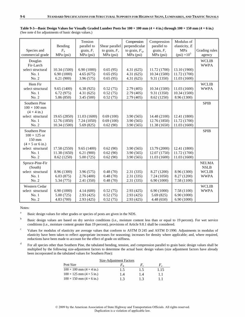
9-6 STANDARD SPECIFICATIONS FOR STRUCTURAL SUPPORTS FOR HIGHWAY SIGNS, LUMINAIRES, AND TRAFFIC SIGNALS
Table 9-3—Basic Design Values for Visually Graded Lumber Posts for 100 × 100 mm (4 × 4 in.) through 100 × 150 mm (4 × 6 in.) (See note d for adjustments of basic design values.)
Species and commercial grade
Bending Fb
MPa (psi)
Tension parallel to grain, Ft
MPa (psi)
Shear parallel to grain, Fv MPa (psi)
Compression perpendicular to grain, Fcp MPa (psi)
Compression parallel to grain, Fc
MPa (psi)
Modulus of elasticity, E
MPa (psi) ×103
Grading rules agency
Douglas Fir-Larch
select structural No. 1 No. 2
10.34 (1500) 6.90 (1000) 6.21 (900)
6.90 (1000) 4.65 (675) 3.96 (575)
0.65 (95) 0.65 (95) 0.65 (95)
4.31 (625) 4.31 (625) 4.31 (625)
11.72 (1700) 10.34 (1500) 9.31 (1350)
13.10 (1900) 11.72 (1700) 11.03 (1600)
WCLIB WWPA
Hem Fir select structural
No. 1 No. 2
9.65 (1400) 6.72 (975) 5.86 (850)
6.38 (925) 4.31 (625) 3.45 (500)
0.52 (75) 0.52 (75) 0.52 (75)
2.79 (405) 2.79 (405) 2.79 (405)
10.34 (1500) 9.31 (1350) 8.62 (1250)
11.03 (1600) 10.34 (1500) 8.96 (1300)
WCLIB WWPA
Southern Pine 100 × 100 mm
(4 × 4 in.) select structural
No. 1 No. 2
19.65 (2850) 12.76 (1850) 10.34 (1500)
11.03 (1600) 7.24 (1050) 5.69 (825)
0.69 (100) 0.69 (100) 0.62 (90)
3.90 (565) 3.90 (565) 3.90 (565)
14.48 (2100) 12.76 (1850) 11.38 (1650)
12.41 (1800) 11.72 (1700) 11.03 (1600)
SPIB
Southern Pine 100 × 125 or
150 mm (4 × 5 or 6 in.)
select structural No. 1 No. 2
17.58 (2550) 11.38 (1650) 8.62 (1250)
9.65 (1400) 6.21 (900) 5.00 (725)
0.62 (90) 0.62 (90) 0.62 (90)
3.90 (565) 3.90 (565) 3.90 (565)
13.79 (2000) 12.07 (1750) 11.03 (1600)
12.41 (1800) 11.72 (1700) 11.03 (1600)
SPIB
Spruce-Pine-Fir (South)
select structural No. 1 No. 2
8.96 (1300) 6.03 (875) 5.34 (775)
3.96 (575) 2.76 (400) 2.41 (350)
0.48 (70) 0.48 (70) 0.48 (70)
2.31 (335) 2.31 (335) 2.31 (335)
8.27 (1200) 7.24 (1050) 6.90 (1000)
8.96 (1300) 8.27 (1200) 7.58 (1100)
NELMA NSLB
WCLIB WWPA
Western Cedar select structural
No. 1 No. 2
6.90 (1000) 5.00 (725) 4.83 (700)
4.14 (600) 2.93 (425) 2.93 (425)
0.52 (75) 0.52 (75) 0.52 (75)
2.93 (425) 2.93 (425) 2.93 (425)
6.90 (1000) 5.69 (825) 4.48 (650)
7.58 (1100) 6.90 (1000) 6.90 (1000)
WCLIB WWPA
Notes: a Basic design values for other grades or species of posts are given in the NDS. b Basic design values are based on dry service conditions (i.e., moisture content less than or equal to 19 percent). For wet service
conditions (i.e., moisture content greater than 19 percent), provisions of Article 9.8.1 shall be considered. c Values for modulus of elasticity are average values that conform to ASTM D 245 and ASTM D 1990. Adjustments in modulus of
elasticity have been taken to reflect appropriate increases for seasoning; increases for density where applicable; and, where required, reductions have been made to account for the effect of grade on stiffness.
d For all species other than Southern Pine, the tabulated bending, tension, and compression parallel to grain basic design values shall be multiplied by the following size-adjustment factors to determine the actual basic design values (size adjustment factors have already been incorporated in the tabulated values for Southern Pine):
Size-Adjustment Factors Post Size Fb Ft Fc 100 × 100 mm (4 × 4 in.) 1.5 1.5 1.15 100 × 125 mm (4 × 5 in.) 1.4 1.4 1.1 100 × 150 mm (4 × 6 in.) 1.3 1.3 1.1
© 2009 by the American Association of State Highway and Transportation Officials. All rights reserved.Duplication is a violation of applicable law.

SECTION 9: WOOD DESIGN 9-7
Table 9-4—Basic Design Values for Visually Graded Lumber Posts 125 × 125 mm (5 × 5 in.) and Larger
Species and commercial grade
Bending Fb
MPa (psi)
Tension parallel to grain, Ft
MPa (psi)
Shear parallel to grain, Fv
MPa (psi)
Compression perpendicular to grain, Fcp MPa (psi)
Compression parallel to grain, Fc
MPa (psi)
Modulus of elasticity, E MPa (psi)
× 103 Grading rules
agency Douglas Fir-Larch select structural
No. 1 No. 2
10.34 (1500) 8.27 (1200) 5.17 (750)
6.90 (1000) 5.69 (825) 3.27 (475)
0.59 (85) 0.59 (85) 0.59 (85)
4.31 (625) 4.31 (625) 4.31 (625)
7.93 (1150) 6.90 (1000) 4.83 (700)
11.03 (1600) 11.03 (1600) 8.96 (1300)
WCLIB
Douglas Fir-Larch select structural
No. 1 No. 2
10.34 (1500) 8.27 (1200) 4.83 (700)
6.90 (1000) 5.69 (825) 3.27 (475)
0.59 (85) 0.59 (85) 0.59 (85)
4.31 (625) 4.31 (625) 4.31 (625)
7.93 (1150) 6.90 (1000) 3.27 (475)
11.03 (1600) 11.03 (1600) 8.96 (1300)
WWPA
Hem Fir select structural
No. 1 No. 2
8.27 (1200) 6.72 (975) 3.96 (575)
5.52 (800) 4.50 (650) 2.59 (375)
0.48 (70) 0.48 (70) 0.48 (70)
2.79 (405) 2.79 (405) 2.79 (405)
6.72 (975) 5.86 (850) 3.96 (575)
8.96 (1300) 8.96 (1300) 7.58 (1100)
WCLIB
Hem Fir select structural
No. 1 No. 2
8.27 (1200) 6.55 (950) 3.62 (525)
5.52 (800) 4.50 (650) 2.41 (350)
0.48 (70) 0.48 (70) 0.48 (70)
2.79 (405) 2.79 (405) 2.79 (405)
6.72 (975) 5.86 (850) 2.59 (375)
8.96 (1300) 8.96 (1300) 7.58 (1100)
WWPA
Southern Pine select structural
No. 1 No. 2
10.34 (1500) 9.31 (1350) 5.86 (850)
6.90 (1000) 6.21 (900) 3.79 (550)
0.76 (110) 0.76 (110) 0.69 (100)
2.59 (375) 2.59 (375) 2.59 (375)
6.55 (950) 5.69 (825) 3.62 (525)
10.34 (1500) 10.34 (1500) 8.27 (1200)
SPIB
Spruce-Pine-Fir (South) select structural
No. 1 No. 2
6.90 (1000) 5.52 (800) 3.27 (475)
4.65 (675) 3.79 (550) 2.24 (325)
0.45 (65) 0.45 (65) 0.45 (65)
2.31 (335) 2.31 (335) 2.31 (335)
4.83 (700) 4.31 (625) 2.93 (425)
8.27 (1200) 8.27 (1200) 6.90 (1000)
NELMA NSLB
WWPA
Western Cedar select structural
No. 1 No. 2
7.58 (1100) 6.03 (875) 3.79 (550)
5.00 (725) 4.14 (600) 2.41 (350)
0.48 (70) 0.48 (70) 0.48 (70)
2.93 (425) 2.93 (425) 2.93 (425)
6.38 (925) 5.52 (800) 3.80 (550)
6.90 (1000) 6.90 (1000) 5.52 (800)
WCLIB
Western Cedar select structural
No. 1 No. 2
7.58 (1100) 6.03 (875) 3.45 (500)
5.00 (725) 4.14 (600) 2.41 (350)
0.48 (70) 0.48 (70) 0.48 (70)
2.93 (425) 2.93 (425) 2.93 (425)
6.38 (925) 5.52 (800) 2.59 (375)
6.90 (1000) 6.90 (1000) 5.52 (800)
WWPA
Notes: a Basic design values for other grades or species of posts are given in the NDS. b Basic design values are based on dry service conditions (i.e., moisture content less than or equal to 19 percent), except for Southern
Pine. For wet service conditions (i.e., moisture content greater than 19 percent), provisions of Article 9.8.1 shall be considered. Basic design values for Southern Pine are based on wet service conditions, and they may be used for dry service conditions.
c Values for modulus of elasticity are average values that conform to ASTM D 245 and ASTM D 1990. Adjustments in modulus of elasticity have been taken to reflect appropriate increases for seasoning; increases for density where applicable; and, where required, reductions have been made to account for the effect of grade on stiffness.
Table 9-5—Basic Design Values for Treated Round Timber Poles
Species
Bending Fb
MPa (psi)
Tension parallel to grain, Ft
MPa (psi)
Shear parallel to grain, Fv MPa (psi)
Compression perpendicular to grain, Fcp MPa (psi)
Compression parallel to grain, Fc
MPa (psi)
Modulus of elasticity, E MPa (psi)
× 103 Standard Douglas Fir 13.10 (1900) — 0.79 (115) 1.59 (230) 6.90 (1000) 10.34 (1500) ASTM D 2899Red Pine 10.00 (1450) — 0.59 (85) 1.07 (155) 5.00 (725) 8.83 (1280) ASTM D 2899Southern Pine 12.76 (1850) — 0.76 (110) 1.72 (250) 6.55 (950) 10.34 (1500) ASTM D 2899
Note: a Basic design values are based on wet service conditions (i.e., moisture content greater than 19 percent), and they may be used for dry
service conditions (i.e., moisture content less than or equal to 19 percent).
© 2009 by the American Association of State Highway and Transportation Officials. All rights reserved.Duplication is a violation of applicable law.

9-8 STANDARD SPECIFICATIONS FOR STRUCTURAL SUPPORTS FOR HIGHWAY SIGNS, LUMINAIRES, AND TRAFFIC SIGNALS 9.7—ALLOWABLE STRESSES FOR WOOD MEMBERS
C9.7
Basic design values from Tables 9-3, 9-4, and 9-5 shall be multiplied by all applicable adjustment factors as shownin Table 9-6 to determine the allowable stresses and theeffective modulus of elasticity of wood members.
Round or square cross-sections are not susceptible to lateral torsional buckling. However, lateral torsional buckling should be considered in the case of rectangular sections bent about their major axis. A beam stability factor is provided by the NDS to modify the allowable stresses in cases of bending of rectangular members. The modification of the allowable bending stress for rectangular sign posts may be neglected when the post depth does not exceed the post thickness by more than 50 mm (2 in.).
Cantilever members such as those covered by this Section (i.e., posts and poles) are usually subjected to small axial compressive loads. Therefore, a reduction in the compressive stress to account for the slenderness of the member is not considered. Slenderness should be considered for members subjected to appreciable axial compressive loads. As conservative criteria, slenderness effects should be considered when fc/Fc is greater than 0.02. A column stability factor is provided by the NDS to modify the allowable compressive stresses for the effects of member slenderness.
Table 9-6—Allowable Stresses and Effective Modulus of Elasticity
Posts Poles Allowable bending stress F ′b = (CM)Fb F ′b = (Cu)Fb Allowable tension stress (parallel to grain) F ′t = (CM)Ft — Allowable compression stress (perpendicular to grain ) F ′cp = (CM)Fcp F ′cp = (Cu)Fcp Allowable compression stress (parallel to grain) F ′c = (CM)Fc F ′c = (Cu)Fc Allowable shear stress (parallel to grain) F ′v = (CM)Fv F ′v = (Cu)Fv Effective modulus of elasticity E ′= (CM)E E ′= (1.0)E
Notes: a CM is the wet service factor defined in Article 9.8.1 for posts. See Article 9.8.2 for poles. b Cu is the untreated factor defined in Article 9.8.3. c The Fb , Ft , and Fc values for posts shall include applicable adjustments from the size-adjustment factors given in Table 9-3. 9.8—ADJUSTMENT FACTORS 9.8.1—Wet Service Factor for Posts CM
Basic design values from Tables 9-3 and 9-4 shall be used for the design of posts under dry service conditions,where the moisture content in use will be a maximum of19 percent. If the moisture content of the post is expected toexceed 19 percent, the basic design values shall be multiplied by the wet service factor, CM, specified in Table 9-7.
© 2009 by the American Association of State Highway and Transportation Officials. All rights reserved.Duplication is a violation of applicable law.

SECTION 9: WOOD DESIGN 9-9
Table 9-7—Wet Service Factor, CM
Post Size Fb Ft Fv Fcp Fc E Posts 100 × 100 mm (4 × 4 in.) through 100 × 150 mm (4 × 6 in.)
0.85 1.00 0.97 0.67 0.80 0.90
Posts 125 × 125 mm (5 × 5 in.) and larger 1.00 1.00 1.00 0.67 0.91 1.00
Notes: a When Fb ≤ 7.93 MPa (1150 psi), CM = 1.0 for posts 100 × 100 mm (4 × 4 in.) through 100 × 150 mm (4 × 6 in.). b When Fc ≤ 5.17 MPa (750 psi), CM = 1.0 for Fc of posts 100 × 100 mm (4 × 4 in.) through 100 × 150 mm (4 × 6 in.). c For Southern Pine posts 125 × 125 mm (5 × 5 in.) and larger, CM = 1.0 for all basic design values. 9.8.2—Wet Service Use for Poles
Basic design values in Table 9-5 shall be used for thedesign of poles under wet service conditions, and their use isconservative for dry service conditions.
9.8.3—Untreated Factor for Poles Cu
C9.8.3
When poles are air dried or kiln dried only prior topressure treatment, Cu shall be taken as follows:
• Cu shall be taken as 1.18, for Southern Pine and
• Cu shall be taken as 1.11, for other species.
Basic design values listed in Table 9-5 are provided for treated poles, and they include an adjustment to compensate for strength reductions due to steam conditioning or boultonizing prior to treatment. When poles are air dried or kiln dried only prior to treatment, the untreated factor can be used.
Poles are often ordered by class number only; therefore, the exact seasoning or conditioning process of the supplied poles may not be known. The Specifications and Dimensions for Wood Poles provides general information on seasoning and conditioning processes for various species of poles.
9.9—TAPERED COMPRESSION MEMBERS
C9.9
For the calculations of compression stresses andbuckling loads of tapered compression members withrectangular cross-section, the representative dimension, d, for each face of the member shall be derived as follows:
( ) 0.15 1 tt b t
b
dad d d dd
⎡ ⎤⎛ ⎞= + − − −⎢ ⎥⎜ ⎟⎝ ⎠⎣ ⎦
(9-1)
For the design of tapered members with round cross-
section, the representative diameter D shall be derived usingEq. 9-1 by replacing db by Db, and dt by Dt.
Calculations of the computed compression stress parallel to grain, fc, shall be based on the representative dimensionsof d, for rectangular members, or the representative diameter,D, for round members. In addition, fc at any cross-section of the tapered member shall not exceed the basic compressiondesign value parallel to grain from Tables 9-3, 9-4, or 9-5 multiplied by all applicable adjustment factors specified in Table 9-6.
Eq. 9-1 provides the cross-section dimensions of rectangular or round members at the critical section for compression. The support condition parameter a in Eq. 9-1 accounts for the particular support conditions at the ends of the tapered member. The value a = 0.70 is valid only for tapered cantilever posts and poles.
The values of db and Db are at the groundline section ofthe member. The taper of a pole may be approximated from the tabulated values for minimum circumference at top of pole and at 1.83 m (6 ft) from the butt.
© 2009 by the American Association of State Highway and Transportation Officials. All rights reserved.Duplication is a violation of applicable law.

9-10 STANDARD SPECIFICATIONS FOR STRUCTURAL SUPPORTS FOR HIGHWAY SIGNS, LUMINAIRES, AND TRAFFIC SIGNALS 9.10—STRESS CALCULATIONS
Axial, shear, and bending stresses shall be computed
based on the linear elastic theory.
9.10.1—Shear Stress
C9.10.1
For shear stresses, the maximum induced shear stressparallel to the grain shall be used.
Calculations of F′v in Table 9-6 may be increased by 1/3for Group II and Group III load combinations, as allowed inSection 3, “Loads.” Calculations of F′v in Table 9-6 shall be decreased by ten percent for Group I load combination toaccount for creep and other long-term effects.
Members subjected to shear stress shall be proportioned so that:
1.0v
v
fF
≤′
(9-2)
For shear stress calculations, the maximum shear stress parallel to grain should be used. The general expression to compute the maximum shear stress parallel to grain is:
vVQfIb
= (MPa, psi) (C9-1)
The average shear stress should not be used for wood
beams because the shear strength parallel to the grain (i.e., usually parallel to the longitudinal axis of the member) is much less than the shear strength across the grain (Breyer, 1993).
For a rectangular bending member of width b, and depth d, Eq. C9-1 may be expressed as:
32v
Vfbd
= (MPa, psi) (C9-2)
and, for a solid round bending member of diameter D, Eq. C9-1 may be expressed as:
2163πv
VfD
= (MPa, psi) (C9-3)
9.11—COMBINED STRESSES
Members subjected to combined bending and
compression shall be proportioned to meet the limitations ofArticle 9.11.1. Calculations of F′c and F′b in Table 9-6 may be increased by 1/3 for Group II and Group III load combinations, as allowed in Section 3, “Loads.” Calculationsof F′c and F′b in Table 9-6 shall be decreased by ten percent for Group I load combinations to account for creep and other long-term effects.
© 2009 by the American Association of State Highway and Transportation Officials. All rights reserved.Duplication is a violation of applicable law.

SECTION 9: WOOD DESIGN 9-11
9.11.1—Combined Bending and Axial Compression
C9.11.1
Members subjected to a combination of bending andaxial compression shall be proportioned so that:
2
1.01
c b
c cb
cE
f fF f
FF
⎛ ⎞+ ≤⎜ ⎟′ ⎛ ⎞⎝ ⎠
−′⎜ ⎟⎝ ⎠
(9-3)
where:
20.75 cE
cEe
K EF
LD
′=
⎛ ⎞⎜ ⎟⎝ ⎠
(9-4)
for round members, and:
2cE
cEe
K EF
Ld
′=⎛ ⎞⎜ ⎟⎝ ⎠
(9-5)
calculated in the plane of bending for rectangular members. KcE shall be 0.3 for posts and timber poles.
The effective column length Le may be taken as 2.1Lu for cantilever members.
The term:
1
1 c
cE
fF
−
is a factor that accounts for secondary bending moments that occur as a result of the P-delta effects.
For biaxial bending in rectangular members, the second term of Eq. 9-3 can be substituted by:
1 1
bybx
c cbx by
cEx cEy
fff fF FF F
+⎛ ⎞ ⎛ ⎞−′ −′⎜ ⎟ ⎜ ⎟⎝ ⎠ ⎝ ⎠
The term:
1
1 c
cE
fF
−
is included to be used for conditions where secondary bending effects are significant. Secondary bending effectscan normally be neglected for posts of roadside signs.
9.12—CONNECTIONS
C9.12
Mechanical connections and their installation shallconform to the requirements of the NDS.
Components at mechanical connections, including the wood members, connecting elements, and fasteners, should be proportioned so that the design strength equals or exceeds the required strength for the loads acting on the structure. The strength of the connected wood components should be evaluated considering the net section, eccentricity, shear, tension perpendicular to grain, and other factors that may reduce component strength.
For Group II and Group III load combinations, the nominal design strengths of mechanical connections may be increased by 1/3. For Group I load combination, the nominaldesign strengths of mechanical connections shall be decreased by ten percent. Load duration factors given in the NDS shall not be used.
© 2009 by the American Association of State Highway and Transportation Officials. All rights reserved.Duplication is a violation of applicable law.

9-12 STANDARD SPECIFICATIONS FOR STRUCTURAL SUPPORTS FOR HIGHWAY SIGNS, LUMINAIRES, AND TRAFFIC SIGNALS
9.13—MINIMUM PROTECTION FOR WOOD PRODUCTS
C9.13
Wood products shall be protected from biological attackof wood-destroying organisms, such as decay, fungi, insects, and marine borers. Minimum accepted preservativetreatments for wood posts and poles shall be in accordance toArticles 9.13.1 and 9.13.2, respectively.
Preservative treatments are those that guard wood against decay, insects, and marine borers. The three basic types of pressure preservatives are: • Creosote and creosote solutions,
• Oilborne treatments (e.g., pentachlorophenol and others dissolved in hydrocarbon solvents), and
• Waterborne oxides.
There are a number of variations on each of these categories. The choice of the preservative treatment and the required retention are specified by the standards from the American Wood Preservers’ Association (AWPA).
The use and disposal of some wood preservatives may be controlled or restricted by various local, state, or governmental agencies.
9.13.1—Preservative Treatment for Posts
C9.13.1
Posts shall be pressure treated in accordance with thestandards C2 and C14 in the Book of Standards.
The following are some of the preservatives for protection of wood posts: • Creosote, creosote–coal tar, or creosote petroleum,
• Pentachlorophenol (PA),
• Ammonical copper arsenate (ACA),
• Aammonical copper zinc arsenate (ACZA), and
• Chromated copper arsenate (CCA).
AWPA standards C2 and C14 cover preservative treatments and specify minimum retention for the listed preservatives for different species of wood posts.
9.13.2—Preservative Treatment for Poles C9.13.2
Round poles shall be pressure treated in accordance with
standards C4 and C14 in the Book of Standards. The following are some of the preservatives for
protection of round timber poles: • Creosote,
• Pentachlorophenol (PA),
• Ammonical copper arsenate (ACA),
• Aammonical copper zinc arsenate (ACZA), and
• Chromated copper arsenate (CCA).
Creosote–coal tar and creosote petroleum are not recommended for round timber poles. AWPA standards C4 and C14 cover preservative treatments and specify minimum retention for the listed preservatives for different species of round timber poles.
© 2009 by the American Association of State Highway and Transportation Officials. All rights reserved.Duplication is a violation of applicable law.

SECTION 9: WOOD DESIGN 9-13
9.14—REFERENCES
AF&PA. 1997. Design Values for Wood Construction, Supplement to the 1997 Edition—National Design Specification. American Forest and Paper Association, Washington, DC.
AF&PA. 1997. National Design Specification for Wood Construction, ANSI/AF&PA NDS-1997. American Forest and Paper Association, Washington, DC.
American Institute of Timber Construction. 1994. Timber Construction Manual, Fourth Edition. John Wiley and Sons, New York, NY.
ANSI. 1992. Specifications and Dimensions for Wood Poles, ANSI O5.1-1992. American National Standard Institute, New York, NY.
ASTM. 1997. “Standard Methods for Establishing Design Stresses for Round Timber Piles,” ASTM D 2899-86. In Annual Book of ASTM Standards. American Society for Testing and Materials, West Conshohocken, PA.
ASTM. 1997. “Standard Practice for Establishing Allowable Properties for Visually Graded Dimension Lumber from In-Grade Test of Full-Size Specimens,” ASTM D 1990-91. In Annual Book of ASTM Standards. American Society for Testingand Materials, West Conshohocken, PA.
ASTM. 1997. “Standard Practice for Establishing Structural Grades and Related Allowable Properties for Visually GradedLumber,” ASTM D 245-93. In Annual Book of ASTM Standards. American Society for Testing and Materials, West Conshohocken, PA.
ASTM. 1997. “Standard Specification and Test Method for Establishing Recommended Design Stresses for Round TimberConstruction Poles,” ASTM D 3200-74 (Reapproved 1994). In Annual Book of ASTM Standards. American Society forTesting and Materials, West Conshohocken, PA.
ASTM. 1997. “Standard Specifications for Round Timber Piles," ASTM D 25-91. In Annual Book of ASTM Standards. American Society for Testing and Materials, West Conshohocken, PA.
ASTM. 1997. “Standard Test Methods for Establishing Clear Wood Strength Values,” ASTM D 2555-88. In Annual Book of ASTM Standards. American Society for Testing and Materials, West Conshohocken, PA.
AWPA. 1996. Book of Standards 1996. American Wood Protection Association (formerly the American Wood Preservers’Association), Birmingham, AL.
Breyer, Donald E. 1993. Design of Wood Structures. McGraw–Hill, New York, NY.
© 2009 by the American Association of State Highway and Transportation Officials. All rights reserved.Duplication is a violation of applicable law.

10-i
SECTION 10: SERVICEABILITY REQUIREMENTS
TABLE OF CONTENTS 10 10.1—SCOPE..............................................................................................................................................................................10-1
10.2—DEFINITIONS .................................................................................................................................................................10-1
10.3—NOTATION......................................................................................................................................................................10-1
10.4—DEFLECTION .................................................................................................................................................................10-1 10.4.1—Overhead Bridge Supports for Signs and Traffic Signals.....................................................................................10-2 10.4.2—Cantilevered Supports for Signs, Luminaires, and Traffic Signals ......................................................................10-2
10.4.2.1—Vertical Supports .........................................................................................................................................10-2 10.4.2.2—Horizontal Supports.....................................................................................................................................10-3
10.4.3—Vibration.................................................................................................................................................................10-3 10.4.3.1—Requirements for Individual Truss Members .............................................................................................10-4
10.5—CAMBER .........................................................................................................................................................................10-4
10.6—REFERENCES.................................................................................................................................................................10-6
© 2009 by the American Association of State Highway and Transportation Officials. All rights reserved.Duplication is a violation of applicable law.

10-1
SECTION 10:
SERVICEABILITY REQUIREMENTS 10.1—SCOPE
This Section provides serviceability requirements for support structures.
10.2—DEFINITIONS
Camber—The condition of the horizontal support being arched.
Quadri-Chord Truss—A horizontal member composed of four longitudinal chords connected by bracing.
Rake—To slant or incline from the vertical.
Tri-Chord Truss—A horizontal member composed of three longitudinal chords connected by bracing.
10.3—NOTATION
dDL = deflection at free end of horizontal support under dead load (mm, in.) dP = deflection at tip of vertical support under dead load from horizontal cantilevered support (mm, in.) dPDL = deflection at free end of horizontal support caused by slope at the tip of the vertical support (mm, in.) dTOTAL = total dead load deflection at free end of horizontal support (mm, in.) E = modulus of elasticity (MPa, psi) H = height of vertical support (mm, in.) I = moment of inertia of vertical support (mm4, in.4) L = distance between supports for an overhead bridge structure; distance from vertical support to free end for
horizontal cantilevered support (mm, in.) M = moment caused by dead loads applied to the vertical support at the connection of the horizontal support (N-mm,
lb-in.) r = radius of gyration (mm, in.) u = prefabricated camber (slope) in the horizontal cantilevered arm (mm/mm, in./in.)
10.4—DEFLECTION
C10.4
Highway support structures of all materials should bedesigned to have adequate structural stiffness that will resultin acceptable serviceability performance. Deflections forspecific structure types shall be limited as provided inArticles 10.4.1 and 10.4.2. Permanent camber for specificstructure types shall be provided per Article 10.5.
The deflection limits that are set by these Specifications are to serve two purposes. The first purpose is to provide an aesthetically pleasing structure under dead load conditions. The second purpose is to provide adequate structural stiffness that will result in acceptable serviceability performance under applied loads.
© 2009 by the American Association of State Highway and Transportation Officials. All rights reserved.Duplication is a violation of applicable law.

10-2 STANDARD SPECIFICATIONS FOR STRUCTURAL SUPPORTS FOR HIGHWAY SIGNS, LUMINAIRES, AND TRAFFIC SIGNALS
10.4.1—Overhead Bridge Supports for Signs and Traffic Signals
C10.4.1
For overhead bridge monotube and truss structuressupporting sign and traffic signals, the maximum verticaldeflection of the horizontal support resulting from Group I load combination with the addition of ice loads (i.e., deadload plus ice) shall be limited to L/150, where L is the span length. For those locations where ice loading is notapplicable, only deflection resulting from Group I load combination shall be used.
Research was sponsored by the Arizona Department of Transportation (Ehsani et al. 1984; Martin et al. 1985) to determine an appropriate deflection limitation for steel monotube bridge support structures. This research included field tests and analytical studies using computer modeling. The studies investigated the static and dynamic behavior of monotube bridge sign support structures. It determined a dead load deflection limit that should be specified for monotube bridge structures. The 1989 Interim Specification was revised to limit deflection to the span divided by 150 for dead and ice load applications based on this research, replacing the previous limit of d
2/400 in feet, where d was the depth of the sign panel in feet. A later study (Lundgren, 1989) indicated that because the deflection criterion was an aesthetic limitation, it could be increased to the span divided by 100; however, no additional work has been found to justify changing the deflection limit to a more liberal value. Although this study considered only steel members, the deflection limit has been generalized for other materials because aesthetics was the governing consideration.
Other types of overhead bridge sign supports (i.e., two-chord, tri-chord, and quadri-chord trusses) generally have higher stiffness than the monotube type. It is believed that this dead load deflection limit of the span divided by 150 (i.e., L/150) could be adopted as a conservative limit for those types of overhead bridge sign and traffic signal support structures made with two-chord, tri-chord, or quadri-chord trusses.
10.4.2—Cantilevered Supports for Signs, Luminaires,and Traffic Signals
10.4.2.1—Vertical Supports
C10.4.2.1
The horizontal deflection limits for vertical supports, such as street lighting poles, traffic signal structures, and signstructures, shall be as follows: • Under Group I load combination (dead load only), the
deflection at the top of vertical supports with transverseload applications shall be limited to 2.5 percent of thestructure height; and
• Under Group I load combination (dead load only), the slope at the top of vertical supports with moment load applications shall be limited to 30 mm/m (0.35 in./ft).
For luminaire support structures under Group II load combination (i.e., dead load and wind), deflection shall belimited to 15 percent of the structure height.
Deflections shall be computed by usual methods orequations for elastic deflections. For prestressed concretemembers, the effects of cracking and reinforcement onmember stiffness shall be considered.
The dead load deflection and slope limitations were developed based on aesthetic considerations. The 2.5 percent deflection limit was developed for transverse load applications, such as strain pole applications, where a dead load caused by span-wire tension could cause unsightly deflection. The horizontal linear displacement at the top of the structure is measured in relation to a tangentto the centerline at the structure’s base. The slope limitation of 30 mm/m (0.35 in./ft), which is equivalent to an angular rotation of 1º 40′, was initially developed for street lighting poles with a single mast arm, where the mast arm applied a concentrated dead load moment that could also cause unsightly deflections. It is measured by the angular rotation of the centerline at the top of the structure in relation to the centerline at its base. The concentrated moment loads result from the effect of eccentric loads of single or unbalanced multiple horizontally mounted arm members and their appurtenances.
© 2009 by the American Association of State Highway and Transportation Officials. All rights reserved.Duplication is a violation of applicable law.

SECTION 10: SERVICEABILITY REQUIREMENTS 10-3
The 15 percent deflection limitation for group II load combination is not a serviceability requirement, but it constitutes a safeguard against the design of highly flexible structures. It is intended mainly for high-level lighting poles. The deflections are calculated without the applied safetyfactor in Article 4.8.2, and second-order effects are normally considered in the analysis.
10.4.2.2—Horizontal Supports
C10.4.2.2
Adequate stiffness shall be provided for the horizontalsupports of cantilevered sign and traffic signal structures thatwill result in acceptable serviceability performance.
Galloping and truck gust-induced vibration deflectionsof cantilevered single-arm sign supports and traffic signalarms should not be excessive so as to result in a serviceability problem, as specified in Article 11.8.
No dead load deflection limit is prescribed for horizontal supports of cantilevered sign and traffic signal structures. Stiffness requirements are determined by the Designer. Structures are typically raked or the horizontal supports are cambered such that the deflection at the end of the arm is above a horizontal reference line for the unloaded configuration, which provides the appearance of a structure that is not overloaded. Camber requirements for cantilevered sign and traffic signal structures are provided in Article 10.5.
10.4.3—Vibration
C10.4.3
Structural supports that are susceptible to damagingvibrations and not designed for fatigue in accordance withSection 11 should be equipped with appropriate damping orenergy-absorbing devices. All aluminum overhead bridge sign and traffic signal support structures should be equippedwith appropriate damping or energy-absorbing devices toprevent significant wind-induced vibration in the structure, both before and after installation of sign panels or trafficsignals.
A mitigation device is not always mandatory if the structure is designed for fatigue in accordance with Section 11. Should the structure exhibit vibrations in the field, a mitigation device may be considered.
Section 11, “Fatigue Design,” contains provisions for designing various structural supports for fatigue using design loads that are a result of wind-induced vibrations and truck gust-induced vibrations.
Vibrations may be caused by wind-induced loads, such as galloping or vortex shedding. Moving traffic may induce gusts on nearby structures, such as a large truck passing under overhead sign structures. Vibrations may also be a result of support movement, such as those found on bridges and elevated roadways.
For street-lighting poles, reducing vibration that is caused by wind or traffic-induced vibration of elevatedroadways is important to reduce the potential for fatigue damage and to increase lamp life (Van Dusen, 1965 and 1968). Mitigation by using a Stockbridge-type damper is suggested by Burt and LeBlanc (1974) and by Dusel and Bon (1986). Vibrations caused by wind have been controlled in street lighting poles with the impact damper (Minor, 1973).
The Stockbridge-type vibration damper has been used to control vibration of aluminum overhead bridge sign structures (Lengel and Sharp 1969). For steel traffic signal structures with mast arms, research (McDonald et al., 1995) has suggested avoiding configurations that are susceptible to galloping, such as rigidly mounted traffic signals. Before these configurations (e.g., signals with an articulated connection to the arm) are used on a given structure, their acceptability from a traffic control perspective should be investigated. Permanent horizontal plane sign panels have been shown to reduce or eliminate galloping vibrations for some installations with rigidly mounted traffic signals, as discussed in Article 11.7.1.
© 2009 by the American Association of State Highway and Transportation Officials. All rights reserved.Duplication is a violation of applicable law.
10-4 STANDARD SPECIFICATIONS FOR STRUCTURAL SUPPORTS FOR HIGHWAY SIGNS, LUMINAIRES, AND TRAFFIC SIGNALS
Steel and aluminum overhead bridge sign and/or traffic signal support structures and cantilevered sign supports may be subject to damaging vibrations and oscillations when sign panels and/or traffic signals are not in place during erection or maintenance of the structure. To avoid these vibrations and oscillations, considerations should be given to providing temporary damping devices attached to the structure, such as blank sign panels.
10.4.3.1—Requirements for Individual Truss Members
C10.4.3.1
The Specifications’ limitations for L/r ratios should beadequate to prevent excessive vibration.
Vibration in truss structures can occur in individual members. Slender tension members and redundant diagonals are particularly susceptible to vibration. Resistance to local vibrations can be provided by increasing member stiffness, thereby reducing flexural deflection and raising vibration response frequencies.
10.5—CAMBER
C10.5
Permanent camber equal to L/1000, where L is the unsupported length of the horizontal support, shall beprovided in addition to dead load camber for overhead signand traffic signal structures.
The camber requirement applies to overhead bridge sign and traffic signal supports and to sign and traffic signal supports with a horizontal cantilevered support. The permanent camber can aid in compensating for deflections resulting from foundation rotation. The permanent camber is in addition to the dead load camber, which compensates for dead load deflection.
Camber is the condition of the horizontal support being arched. Permanent camber is the condition of the horizontal support being arched upward after application of the dead loads. The horizontal support should be arched upward such that the vertical distance from the attachment point(s) to location of maximum deflection for the horizontal support is equal to L/1000. The permanent camber provides the visual effect of a low-pitched arch, which is more appealing than a horizontal support that is deflected downward.
Permanent camber can be provided by raking the vertical support and/or cambering the horizontal support. Raking the vertical support involves installing the vertical support with an initial deflection. The vertical support is raked during construction by adjusting the leveling nuts at the base of the structure. Raking the vertical support may result in the anchor bolts not being perpendicular to the support’s base plate, and it can result in anchor bolt nuts not being properly tightened against the base plate. Cambering the horizontal support involves fabricating the support with an initial slope or curvature.
The following procedure may be used to calculate the camber required to compensate for dead load deflection in a cantilevered sign support structure with a monotube vertical support.
The cantilevered horizontal support should be cambered during fabrication, such that the permanent camber after application of dead load is a minimum of L/1000 above the horizontal plane, where L is the span of the horizontal support.
© 2009 by the American Association of State Highway and Transportation Officials. All rights reserved.Duplication is a violation of applicable law.

SECTION 10: SERVICEABILITY REQUIREMENTS 10-5
Figure 10-1—Camber of Cantilevered Sign Structure
The following procedure shown is for a nontapered
vertical support with a constant stiffness. Determine horizontal deflection at tip of vertical support
due to dead load (deflection of vertical support not shown in figure):
2
2PMHd
EI= (C10-1)
Determine deflection of horizontal support due to slope
at tip of vertical support:
2 PPDL
dd L
H= (C10-2)
Determine deflection of horizontal support due to dead
load acting on the horizontal support, dDL. Calculate total dead load deflection at the tip of the
cantilevered arm:
TOTAL DL PDLd d d= + (C10-3) Determine the slope u of the prefabricated camber in the
horizontal support, such that:
11000
DL PDLd du
L L= + + (C10-4)
This slope will result in a final deflection at the end of
the horizontal arm equal to L/1000 above the horizontal plane.
Provide fabrication details indicating the prefabricated camber (slope) u in horizontal support.
The above procedure does not consider the raking of the vertical support.
© 2009 by the American Association of State Highway and Transportation Officials. All rights reserved.Duplication is a violation of applicable law.

10-6 STANDARD SPECIFICATIONS FOR STRUCTURAL SUPPORTS FOR HIGHWAY SIGNS, LUMINAIRES, AND TRAFFIC SIGNALS
A slope for some cantilevered horizontal supports has been provided by tilting the arm by a small angle at its base connection.
When the total dead load deflection is very small, some vertical supports have been raked to compensate for the full deflection of the cantilevered horizontal support.
10.6—REFERENCES
Brockenbrough, R. L. 1970. Suggested Structural Design Criteria for Steel Lighting Standards, US Steel Report 6, Project No. 57-019-450(6), January 1970.
Burt, J. O., and E. J. LeBlanc. 1974. Luminaire Vibration Suppression Study, Report No. 75. Louisiana Department of Highways, Baton Rouge, LA; Federal Highway Administration, Washington, DC.
Dusel, J. P., and V. D. Bon. 1986. Effectiveness of Stockbridge-Type Vibration Dampers on Reducing Fatigue Failures of Luminaires and Mast Arms on Lighting Standards Installed on Bridges. California Department of Transportation, Sacramento, CA.
Ehsani, M. R., S. K. Chakrabarti, and R. Bjorhovde. 1984. Static and Dynamic Behavior of Monotube Span-Type Sign Structures, Report No. FHWA/AZ-84/194-I. Arizona Department of Transportation, Phoenix, AZ.
Lengel, J. S., and M. L. Sharp. 1969. “Vibration and Damping of Aluminum Overhead Sign Structures,” Highway Research Record, Transportation Research Board, National Research Council, Washington, DC, No. 259.
Lundgren, H. R. 1989. Evaluation of Monotube Sign Support Structure, Report No. FHWA-AZ89-829. Arizona Department of Transportation, Phoenix, AZ.
Martin, K. A., M. R. Ehsani, and R. Bjorhovde. 1985. Field Testing of Monotube Sign Support Structures, Report No. FHWA/AZ-86/237. Arizona Department of Transportation, Phoenix, AZ.
McDonald, J. R., K. C. Mehta, W. W. Oler, and N. Pulipaka. 1995. Wind Load Effects on Signs, Luminaires, and Traffic Signals Structures, Report No. 1303-F. Wind Engineering Research Center, Texas Department of Transportation, Lubbock, TX.
Minor, R. C. 1973. “Damp Destructive Pole Vibration,” Electric Light and Power. December 1973.
Van Dusen, H. A. 1968. “Street Lighting Luminaire Vibration,” Illuminating Engineering. February 1968.
Van Dusen, H. A. and D. Wandler. 1965. “Street Lighting Pole Vibration Research,” Illuminating Engineering. November 1965.
© 2009 by the American Association of State Highway and Transportation Officials. All rights reserved.Duplication is a violation of applicable law.

11-i
SECTION 11: FATIGUE DESIGN
TABLE OF CONTENTS 11 11.1—SCOPE..............................................................................................................................................................................11-1
11.2—DEFINITIONS .................................................................................................................................................................11-1
11.3—NOTATION......................................................................................................................................................................11-1
11.4—APPLICABLE STRUCTURE TYPES............................................................................................................................11-3
11.5—DESIGN CRITERIA........................................................................................................................................................11-3
11.6—FATIGUE IMPORTANCE FACTORS ..........................................................................................................................11-5
11.7—FATIGUE DESIGN LOADS...........................................................................................................................................11-6 11.7.1—Galloping................................................................................................................................................................11-7 11.7.2—Vortex Shedding ....................................................................................................................................................11-9 11.7.3—Natural Wind Gust ...............................................................................................................................................11-11 11.7.4—Truck-Induced Gust .............................................................................................................................................11-12
11.8—DEFLECTION ...............................................................................................................................................................11-13
11.9—FATIGUE RESISTANCE .............................................................................................................................................11-13
11.10—REFERENCES.............................................................................................................................................................11-23
© 2009 by the American Association of State Highway and Transportation Officials. All rights reserved.Duplication is a violation of applicable law.

11-1
SECTION 11:
FATIGUE DESIGN 11.1—SCOPE
C11.1
This Section contains provisions for the fatigue design of cantilevered and noncantilevered steel and aluminum structural supports for highway signs, luminaires, and traffic signals.
This Section focuses on fatigue, which is defined herein as the damage that may result in fracture after a sufficient number of stress fluctuations. It is based on NCHRP Report 412, Fatigue Resistant Design of Cantilevered Signal, Sign and Light Supports (Kaczinski et al., 1998), NCHRP Report 469, Fatigue-Resistant Design of Cantilever Signal, Sign, and Light Supports (Dexter and Ricker, 2002), and NCHRP Report 494, Structural Supports for Highway Signs, Luminaires, and Traffic Signals (Fouad et al., 2003).
11.2—DEFINITIONS
Constant-Amplitude Fatigue Limit (CAFL)—Nominal stress range below which a particular fatigue detail can withstand an infinite number of repetitions without fatigue failure.
Fatigue—Damage resulting in fracture caused by stress fluctuations.
In-Plane Bending—Bending in-plane for the main member (column). At the connection of an arm or arm’s built-up box to a vertical column, the in-plane bending stress range in the column is a result of galloping or truck-induced gust loads on the arm and/or arm’s attachments.
Limit State Wind Load Effect—A specifically defined load criteria.
Load-Bearing Attachment—Attachment to main member where there is a transverse load range in the attachment itself in addition to any primary stress range in the main member.
Nonload-Bearing Attachment—Attachment to main member where the only significant stress range is the primary stress in the main member.
Out-of-Plane Bending—Bending out-of-plane for the main member (column). At the connection of an arm or arm’s built-up box to a vertical column, the out-of-plane bending stress range in the column is a result of natural wind-gust loads on the arm and the arm’s attachments.
Pressure Range—Pressure due to a limit state wind load effect that produces a stress range.
Stress Range—The algebraic difference between extreme stresses used in fatigue design.
Yearly Mean Wind Velocity—Long-term average of the wind speed for a given area.
11.3—NOTATION
b = flat-to-flat width of a multisided section (m, ft) Cd = appropriate drag coefficient from Section 3, “Loads,” for given attachment or member d = diameter of a circular section (m, ft) D = inside diameter of exposed end of female section for slip-joint splice (mm, in.) E = modulus of elasticity (MPa, ksi) fn = first natural frequency of the structure (cps) fn1 = first modal frequency (cps) (F)n = fatigue strength (CAFL) (MPa, ksi) g = acceleration of gravity (9810 mm/s2, 386 in./s2) H = effective weld throat (mm, in.)
© 2009 by the American Association of State Highway and Transportation Officials. All rights reserved.Duplication is a violation of applicable law.

11-2 STANDARD SPECIFICATIONS FOR STRUCTURAL SUPPORTS FOR HIGHWAY SIGNS, LUMINAIRES, AND TRAFFIC SIGNALS I = moment of inertia (mm4, in.4) Iavg = average moment of inertia for a tapered pole (mm4, in.4) Itop = moment of inertia at top of tapered pole (mm4, in.4) Ibottom = moment of inertia at bottom of tapered pole (mm4, in.4) IF = importance factors applied to limit state wind load effects to adjust for the desired level of structural reliability L = length of the pole (Article 11.7.2) (mm, in.) L = slip-splice overlap length (example 1 of Figure 11-1) (mm, in.) L = length of reinforcement at handhole (example 13 of Figure 11-1) (mm, in.) L = length of longitudinal attachment (examples 12, 14, and 15 of Figure 11-1) (mm, in.) PG = galloping-induced vertical shear pressure range (Pa, psf) PNW = natural wind gust pressure range (Pa, psf) PTG = truck-induced gust pressure range (Pa, psf) PVS = vortex shedding-induced pressure range (Pa, psf) r = radius of chord or column (mm, in.) R = transition radius of longitudinal attachment (mm, in.) Sn = Strouhal number SR = nominal stress range of the main member or branching member (MPa, ksi) t = thickness (mm, in.) tb = wall thickness of branching member (mm, in.) tc = wall thickness of main member (column) (mm, in.) tp = plate thickness of attachment (mm, in.) Vc = critical wind velocity for vortex shedding (m/s, mph) Vmean = yearly mean wind velocity for a given area (m/s, mph) VT = truck speed for truck-induced wind gusts (m/s, mph) W = weight of the luminaire (N, k) w = weight of the pole per unit length (N/mm, k/in.) β = damping ratio α = angle of transition taper of longitudinal attachment (example 14 of Figure 11-1) (°) α = ovalizing parameter for bending in the main member (note b of Table 11-2) ΔF = constant amplitude fatigue limit stress range (MPa, ksi) Δσ = indication of stress range in member
© 2009 by the American Association of State Highway and Transportation Officials. All rights reserved.Duplication is a violation of applicable law.

SECTION 11: FATIGUE DESIGN 11-3
11.4—APPLICABLE STRUCTURE TYPES
C11.4
Design for fatigue shall be required for the following type structures:
a. overhead cantilevered sign structures,
b. overhead cantilevered traffic signal structures,
c. high-level, high-mast lighting structures,
d. overhead noncantilevered sign structures, and
e. overhead noncantilevered traffic signal structures.
NCHRP Report 412 is the basis for the fatigue design provisions for cantilevered structures. NCHRP Report 494 is the basis for the fatigue design provisions for noncantilevered support structures. The fatigue design procedures outlined in this Section may be applicable to steel and aluminum structures in general. However,only specific types of structures are identified for fatigue design in this Article. Common lighting poles and roadside signs are not included because they are smaller structures and normally have not exhibited fatigue problems. An exception would be square lighting poles, as they have exhibited poor fatigue performance. Square cross-sections have been much more prone to fatigue problems than round cross-sections. Caution should be exercised regarding the use of square lighting poles even when a fatigue design is performed. The provisions of this Section are not applicable for the design of span-wire (strain) poles.
11.5—DESIGN CRITERIA
C11.5
Cantilevered and noncantilevered support structures shall be designed for fatigue to resist each of the applicableequivalent static wind load effects specified in Article 11.7, and modified by the appropriate importance factors given in Article 11.6. Stresses due to these loads on all components, mechanical fasteners, and weld details shall be limited to satisfy the requirements of their respective detail categories within the constant-amplitude fatigue limits (CAFL) provided in Article 11.9.
Accurate load spectra and life prediction techniques for defining fatigue loadings are generally not available. The assessment of stress fluctuations and the corresponding number of cycles for all wind-induced events (lifetime loading histogram) is practically impossible. With this uncertainty, the design of sign, luminaire, and traffic signal supports for a finite fatigue life becomes impractical. Therefore, an infinite life fatigue design approach isrecommended and is considered sound practice. Fatigue stress limits are based on the CAFL. The CAFL values provided in Table 11-3 are approximately the same as those given in Table 10.3.1A of the Standard Specifications for Highway Bridges.
An infinite life fatigue approach was developed in an experimental study that considered several critical welded details (Fisher et al. 1993). The infinite life fatigue approach can be used when the number of wind load cycles expected during the lifetime of the structures is greater than the number of cycles at the CAFL. This is particularly the case for structural supports where the wind load cycles in 25 years or greater lifetimes are expected to exceed 100 million cycles, whereas typical weld details reach the CAFL at 10 to 20 million cycles.
© 2009 by the American Association of State Highway and Transportation Officials. All rights reserved.Duplication is a violation of applicable law.

11-4 STANDARD SPECIFICATIONS FOR STRUCTURAL SUPPORTS FOR HIGHWAY SIGNS, LUMINAIRES, AND TRAFFIC SIGNALS
Fatigue-critical details are designed with nominal stress ranges that are below the appropriate CAFL. To assist designers, typical support structure details based on AASHTO and American Welding Society (AWS) fatigue design categories are provided in Table 11-2 and Figure 11-1. The above-referenced details were produced based on a review of state departments of transportation standard drawings and manufacturers’ literature. This list should not be considered a complete set of all possible connection details, but rather it is intended to remove the uncertainty associated with applying the provisions of the Standard Specifications for Highway Bridges to the fatigue design of support structures. Choice of details improves the fatigue resistance of these structures, and it can eliminate or reduce increases in member size required for less fatigue-resistant details.
The notes for Table 11-2 specify the use of Stress Category K2. This stress category corresponds to the category for cyclic punching shear stress in tubular members specified by the AWS Structural Welding Code D1.1—Steel. Fatigue design for the column’s wall under this condition may require sizes of the built-up box connection or column wall thicknesses that are excessive for practical use. For this occurrence, an adequate fatigue-resistant connection other than the built-up box shown in Figure 11-1 should be considered.
Fatigue testing has shown the advantage of ring stiffeners that completely encircle a pole relative to a built-up box connection. For built-up box connections, it is recommended that the width of the box be the same as the diameter of the column (i.e., the sides of the box are tangent to the sides of the column).
Regarding full-penetration groove-welded tube-to-transverse plate connections, NCHRP Report 412 did not fully investigate the effects from the possible use of additional reinforcing fillet welds. Additional research and testing of these types of detail configurations are needed to support future updates of this Section.
Stress categories in Table 11-2 for weld terminations at the end of longitudinal stiffeners were based, in part, on assigned categories for attachments in the AASHTO Bridge Specifications. Fatigue testing of many fillet-welded tube-to-longitudinal stiffener connections indicates that the angle of intersection, the transitional radius to the pole wall, the length of the stiffener, and the ratio of the stiffener thickness to pole wall thickness, for example, all have effects on the fatigue life of the detail. Some tube-to-stiffener connections have a potential to develop high stress concentrations in the tube wall in the vicinity of the weld termination at the end oflongitudinal stiffeners. Testing on poles having wall thickness less than 6 mm (0.25 in.) indicates that longitudinal stiffeners yielded little or no improvement of the fatigue performance of the connection (Koenigs et al., 2003). Until further research can give reliable estimates of the effects of stiffeners, all welds terminating at the end of longitudinal stiffeners shall be classified as Stress Category E′.
© 2009 by the American Association of State Highway and Transportation Officials. All rights reserved.Duplication is a violation of applicable law.

SECTION 11: FATIGUE DESIGN 11-5
Equal leg welds in socket connections have been shown by fatigue testing to have a fatigue strength less than Stress Category E′. The fatigue strength of a socket-welded connection can be improved by using an unequal leg fillet weld.
11.6—FATIGUE IMPORTANCE FACTORS
C11.6
An importance factor, IF, that accounts for the risk of hazard to traffic and damage to property shall be applied to the limit state wind-load effects specified in Article 11.7. Importance factors for traffic signal, sign, and luminaire support structures exposed to the four wind load effects are presented in Table 11-1.
Importance factors are introduced into the Specifications to adjust the level of structural reliability of cantilevered and noncantilevered support structures. Importance factors should be determined by the Owner. For combined structures, where traffic signals and luminaires are joined, theuse of the more conservative importance factor is recommended.
The importance categories and importance factors (rounded to the nearest 0.05) are results from NCHRP Reports 469 and 494. Three categories of support structures are presented in Table 11-1. Structures classified as Category I present a high hazard in the event of failure and should be designed to resist rarely occurring wind loading and vibration phenomena. It is recommended that all structures without effective mitigation devices on roadways with a speed limit in excess of 60 km/hr (35 mph) and average daily traffic (ADT) exceeding 10 000 or average daily truck traffic (ADTT) exceeding 1000 should be classified as Category I structures. ADT and ADTT are forone direction regardless of the number of lanes.
Structures without mitigation devices may be classified
as Category I if any of the following apply:
1. Cantilevered sign structures with a span in excess of 16 m (50 ft) or high-mast towers in excess of 30 m (100 ft),
2. Large sign structures, both cantilevered and noncantilevered, including variable message signs, and
3. Structures located in an area that is known to have wind conditions that are conducive to vibration. Structures should be classified as Category III if they are
located on roads with speed limits of 60 km/hr (35 mph) or less. Structures that are located such that a failure will not affect traffic may be classified as Category III.
All structures not explicitly meeting the Category I or Category III criteria should be classified as Category II.
Maintenance and inspection programs should be considered integral to the selection of the fatigue importance category.
There are many factors that affect the selection of the fatigue category and engineering judgment is required.
© 2009 by the American Association of State Highway and Transportation Officials. All rights reserved.Duplication is a violation of applicable law.

11-6 STANDARD SPECIFICATIONS FOR STRUCTURAL SUPPORTS FOR HIGHWAY SIGNS, LUMINAIRES, AND TRAFFIC SIGNALS
Table 11–1—Fatigue Importance Factors, IF
Fatigue Category Importance Factor, IF Galloping Vortex Shedding Natural Wind Gusts Truck-Induced Gusts
I Sign Traffic Signal
Lighting
1.0 1.0 x
x* x* 1.0
1.0 1.0 1.0
1.0 1.0 x
II Sign Traffic Signal
Lighting
0.70 0.65
x
x* x*
0.65
0.85 0.80 0.75
0.90 0.85
x
Cant
ileve
red
III Sign Traffic Signal
Lighting
0.40 0.30
x
x* x*
0.30
0.70 0.55 0.50
0.80 0.70
x I Sign
Traffic Signal x x
x* x*
1.0 1.0
1.0 1.0
II Sign Traffic Signal
x x
x* x*
0.85 0.80
0.90 0.85
Non
cant
ileve
red
III Sign Traffic Signal
x x
x* x*
0.70 0.55
0.80 0.70
Notes:
x Structure is not susceptible to this type of loading.
* Overhead cantilevered and noncantilevered sign and traffic signal components are susceptible to vortex shedding prior to placement of the signs and traffic signal heads, i.e., during construction.
11.7—FATIGUE DESIGN LOADS
C11.7
To avoid large-amplitude vibrations and to preclude thedevelopment of fatigue cracks in various connection detailsand at other critical locations, cantilevered andnoncantilevered support structures shall be designed to resisteach of the following applicable limit state equivalent staticwind loads acting separately. These loads shall be used tocalculate nominal stress ranges near fatigue-sensitive connection details described in Article 11.5 and deflectionsfor service limits described in Article 11.8.
In lieu of using the equivalent static pressures providedin this Specification, a dynamic analysis of the structure maybe performed using appropriate dynamic load functionsderived from reliable data.
Cantilevered and noncantilevered support structures are exposed to several wind phenomena that can produce cyclic loads. Vibrations associated with these cyclic forces can become significant. NCHRP Report 412 identified galloping, vortex shedding, natural wind gusts, and truck-induced gusts as wind-loading mechanisms that can induce large-amplitude vibrations and/or fatigue damage in cantilevered traffic signal, sign, and light support structures. NCHRP Report 494 identified natural wind gusts and truck-induced gusts as wind-loading mechanisms that can induce large-amplitude vibrations and/or fatigue damage in noncantilevered traffic signal and sign support structures. The amplitude of vibration and resulting stress ranges are increased by the low levels of stiffness and damping possessed by many of these structures. In some cases, the vibration is only a serviceability problem because motorists cannot clearly see the mast arm attachments or are concerned about passing under the structures. In other cases, where deflections may or may not be considered excessive, the magnitudes of stress ranges induced in these structures have resulted in the developmentof fatigue cracks at various connection details including the anchor bolts.
© 2009 by the American Association of State Highway and Transportation Officials. All rights reserved.Duplication is a violation of applicable law.

SECTION 11: FATIGUE DESIGN 11-7
The wind-loading phenomena specified in this section possess the greatest potential for creating large-amplitude vibrations in cantilevered support structures. In particular, galloping and vortex shedding are aeroelastic instabilities that typically induce vibrations at the natural frequency of the structure (i.e., resonance). These conditions can lead to fatigue failures in a relatively short period of time.
Design pressures for four fatigue wind-loading mechanisms are presented as an equivalent static wind pressure range, or a shear stress range in the case of galloping. These pressure (or shear stress) ranges should be applied as prescribed by static analysis to determine stress ranges near fatigue-sensitive details. In lieu of designing for galloping or vortex-shedding limit state fatigue wind load effects, mitigation devices may be used as approved by the Owner. Mitigation devices are discussed in NCHRP Reports 412 and 469.
11.7.1—Galloping
C11.7.1
Overhead cantilevered sign and traffic signal supportstructures shall be designed for galloping-induced cyclic loads by applying an equivalent static shear pressurevertically to the surface area, as viewed in normal elevation of all sign panels and/or traffic signal heads and backplatesrigidly mounted to the cantilevered horizontal support. Thevertical shear pressure range shall be equal to the following:
1000G FP I= (Pa) (11-1)
21G FP I= (psf)
In lieu of designing to resist periodic galloping forces, cantilevered sign and traffic signal structures may be erectedwith effective vibration mitigation devices. Vibrationmitigation devices should be approved by the Owner, andthey should be based on historical or research verification of its vibration damping characteristics.
Alternatively, for traffic signal structures, the Ownermay choose to install approved vibration mitigation devicesif structures exhibit a galloping problem. The mitigation devices should be installed as quickly as possible after thegalloping problem appears.
The Owner may choose to exclude galloping loads forthe fatigue design of overhead cantilevered sign supportstructures with quadri-chord (i.e., four-chord) horizontal trusses.
Galloping, or Den Hartog instability, results in large-amplitude, resonant oscillations in a plane normal to the direction of wind flow. It is usually limited to structures with nonsymmetrical cross-sections, such as sign and traffic signal structures with attachments to the horizontal cantilevered arm. Structures without attachments to the cantilevered horizontal support are not susceptible to galloping-induced wind load effects.
The results of wind tunnel (Kaczinski et al., 1998) and water tank (McDonald et al., 1995) testing, as well as the oscillations observed on cantilevered support structures in the field, are consistent with the characteristics of the galloping phenomena. These characteristics include the sudden onset of large-amplitude, across-wind vibrations that increase with increases in wind velocity. Galloping is typically not caused by wind applied to the support structure, but rather applied to the attachments to the horizontal cantilevered arm, such as signs and traffic signals.
The geometry and orientation of these attachments, as well as the wind direction, directly influence the susceptibility of cantilevered support structures to galloping. Traffic signals are more susceptible to galloping when configured with a backplate. In particular, traffic signal attachments configured with or without a backplate are more susceptible to galloping when subject to flow from the rear. Galloping of sign attachments is independent of aspect ratio and is more prevalent with wind flows from the front of the structure.
© 2009 by the American Association of State Highway and Transportation Officials. All rights reserved.Duplication is a violation of applicable law.

11-8 STANDARD SPECIFICATIONS FOR STRUCTURAL SUPPORTS FOR HIGHWAY SIGNS, LUMINAIRES, AND TRAFFIC SIGNALS
By conducting wind tunnel tests and analytical calibrations to field data and wind tunnel test results, an equivalent static vertical shear of 1000 Pa (21 psf) was determined for the galloping phenomenon. This vertical shear range should be applied to the entire frontal area of each of the sign and traffic signal attachments in a static analysis to determine stress ranges at critical connection details. For example, if a 2.5 × 3.0 m (8 × 10 ft) sign panel is mounted to a horizontal mast arm, a static force of 7500 × IF, N (1680 × IF, lb) should be applied vertically at the area centroid of the sign panel. A study (Florea et al, 2007) has shown that the equivalent static force that an attachment experiences depends on the location along the arm where it is attached. Equivalent static pressures or vertical shear ranges applied to the frontal area of each sign or traffic signal attachment are greater towards the tip of the mast arm. The specification does not consider the effect of the attachment location when calculating the galloping force. Further testing is necessary to verify this and to suggest location-specific ranges.
A pole with multiple horizontal cantilevered arms may be designed for galloping loads applied separately to each individual arm, and need not consider galloping simultaneously occurring on multiple arms.
Overhead cantilevered sign support structures with quadri-chord horizontal trusses do not appear to be susceptible to galloping because of their inherent stiffness.
Two possible means exist to mitigate galloping-induced oscillations in cantilevered support structures. The dynamic properties of the structure or the aerodynamic properties of the attachments can be adequately altered to mitigate galloping. The installation of a device providing positive aerodynamic damping can be used to alter the structure’s response from the aerodynamic effects on the attachments.
A method of providing positive aerodynamic damping to a traffic signal structure involves installing a sign blank mounted horizontally and directly above the traffic signal attachment closest to the tip of the mast arm. This method has been shown to be effective in mitigating galloping-induced vibrations on traffic signal support structures with horizontally mounted traffic signal attachments (McDonald et al., 1995). For vertically mounted traffic signal attachments, a sign blank mounted horizontally near the tip of the mast arm has mitigated large-amplitude galloping vibrations occurring in traffic signal support structures. This sign blank is placed adjacent to a traffic signal attachment, and a separation exists between the sign blank and the top of the mast arm. In both cases, the sign blanks are required to provide a sufficient surface area for mitigation to occur. However, the installation of sign blanks may influence the design of structures for truck-induced wind gusts by increasing the projected area on a horizontal plane. NCHRP Reports 412 and 469 provide additional discussion on this possible mitigation device and on galloping susceptibility and mitigation.
© 2009 by the American Association of State Highway and Transportation Officials. All rights reserved.Duplication is a violation of applicable law.

SECTION 11: FATIGUE DESIGN 11-9
11.7.2—Vortex Shedding
C11.7.2
High-level, high-mast lighting structures shall bedesigned to resist vortex shedding-induced loads for criticalwind velocities less than approximately 20 m/s (45 mph).
The critical wind velocity, Vc (m/s, mph), at whichvortex shedding lock-in can occur may be calculated asfollows:
For circular sections:
n
cn
f dV
S= (m/s) (11-2)
0.68 nc
n
f dV
S= (mph)
For multisided sections:
nc
n
f bV
S= (m/s) (11-3)
0.68 nc
n
f bV
S= (mph)
where fn is a natural frequency of the structure (cps); d and bare the diameter and flat-to-flat width of the horizontal mastarm or pole shaft for circular and multisided sections (m, ft), respectively; and Sn is the Strouhal number. The Strouhal number shall be taken as 0.18 for circular sections, 0.15 for multisided sections, and 0.11 for square or rectangularsections. For a tapered pole, d and b are the average diameter and width.
The equivalent static pressure range to be used for thedesign of vortex shedding-induced loads shall be:
2 0.613
2βc d F
vsV C I
P = (Pa) (11-4)
2 0.00256
2βc d F
vsV C I
P = (psf)
where Vc is expressed in m/s (mph); Cd is the drag coefficientas specified in Section 3, “Loads,” which is based on thecritical wind velocity Vc; and β is the damping ratio, whichmay be estimated as 0.005.
The equivalent static pressure range PVS shall be appliedtransversely to poles (i.e., horizontal direction) andhorizontal mast arms (i.e., vertical direction).
In lieu of designing to resist periodic vortex-shedding forces, effective vibration mitigation devices may be used.
The shedding of vortices on alternate sides of a member may result in oscillations in a plane normal to the direction of wind flow. Typical natural frequencies and member dimensions preclude the possibility of most cantilevered sign and traffic signal support structures from being susceptible to vortex shedding-induced vibrations.
NCHRP Report 469 shows that poles with tapers exceeding 0.0117 m/m (0.14 in./ft) can also experience vortex shedding in lighting structures. Observations and studies indicate that tapered poles can experience vortex shedding in second or third mode vibrations and that those vibrations can lead to fatigue problems. Procedures to consider higher mode vortex shedding on tapered poles are demonstrated in NCHRP Report 469.
Structural elements exposed to steady, uniform wind flows shed vortices in the wake behind the element in a pattern commonly referred to as a von Karmen vortex street. When the frequency of vortex shedding approaches one of the natural frequencies of the structure, usually the first mode (or higher modes as demonstrated in NCHRP Report 469), significant amplitudes of vibration can be caused by a condition termed lock-in. The critical velocity at which lock-in occurs is defined by the Strouhal relationship:
nc
n
f dV
S= (C11-1)
For the first mode of vibration, a lower bound wind
speed can be established for traffic signal and sign structures. Although vortices are shed at low wind velocities for wind speeds less than 5 m/s (16 fps, 11 mph), the vortices do not impart sufficient energy to excite most structures. Typicalnatural frequencies and member diameters for sign and traffic signal support structures result in critical wind velocities well below the 5 m/s (16 fps, 11 mph) threshold for the occurrence of vortex shedding. Because of extremely low levels of damping, vortex shedding may significantly excite resonant vibration. At wind speeds greater than about 20 m/s (65 fps, 45 mph), enough natural turbulence is generated to disturb the formation of vortices. Because Vc is relatively low, the largest values of Cd for the support may be conservatively used.
Horizontal arms may be susceptible to vortex shedding before sign and signal heads are attached, i.e., during construction. Although possible, tests (Kaczinski et al., 1998; McDonald et al., 1995) have indicated that the occurrence of vortex shedding from attachments to cantilevered sign and traffic signal support structures is not critical. These attachments are more susceptible to galloping-induced vibrations.
© 2009 by the American Association of State Highway and Transportation Officials. All rights reserved.Duplication is a violation of applicable law.

11-10 STANDARD SPECIFICATIONS FOR STRUCTURAL SUPPORTS FOR HIGHWAY SIGNS, LUMINAIRES, AND TRAFFIC SIGNALS
Calculation of the first modal frequency for simple pole structures (i.e., without mast arms) can be computed using:
1 41.75πn
EIgfwL
= (C11-2)
(without luminaire mass)
1 3 41.732
2π 0.236nEIgf
WL wL+= (C11-3)
(with luminaire mass) where W is the weight of the luminaire (N, k), w is the weight of the pole per unit length (N/mm, k/in.), g is the acceleration of gravity (9810 mm/s2, 386 in./s2), L is the length of the pole (mm, in.), and I is the moment of inertia of the pole (mm4, in.4). For tapered poles, Iavg is substituted for I, where:
2top bottom
avgI I
I+
= (C11-4)
Itop is the moment of inertia at the tip of the pole and Ibottom is the moment of inertia at the bottom of the pole.
The first modal frequency for poles with mast arms, however, is best accomplished by a finite element-based modal analysis. The mass of the luminaire/mast arm attachments shall be included in the analysis to determine the first mode of vibration transverse to the wind direction. Poles that may not have the attachments installed immediately shall be designed for this worst-case condition. Because the natural frequency of a structure without an attached mass is typically higher than those with an attachment, the resulting critical wind speed and vortex shedding pressure range are also higher for this situation.
© 2009 by the American Association of State Highway and Transportation Officials. All rights reserved.Duplication is a violation of applicable law.

SECTION 11: FATIGUE DESIGN 11-11
11.7.3—Natural Wind Gust
C11.7.3
Cantilevered and noncantilevered overhead sign,overhead traffic signal, and high-level lighting supports shallbe designed to resist an equivalent static natural wind gustpressure range of:
250NW FdCP I= (Pa) (11-5)5.2NW FdCP I= (psf)
where Cd is the appropriate drag coefficient based on theyearly mean wind velocity of 5 m/s (11.2 mph) specified in Section 3, “Loads,” for the considered element to which thepressure range is to be applied. If Eq. C11-5 is used in placeof Eq. 11-5, Cd may be based on the location-specific yearly mean wind velocity Vmean. The natural wind gust pressurerange shall be applied in the horizontal direction to theexposed area of all support structure members, signs, trafficsignals, and/or miscellaneous attachments. Designs fornatural wind gusts shall consider the application of wind gusts for any direction of wind.
The design natural wind gust pressure range is based ona yearly mean wind speed of 5 m/s (11.2 mph). For locationswith more detailed wind records, particularly sites withhigher wind speeds, the natural wind gust pressure may bemodified at the discretion of the Owner.
Because of the inherent variability in the velocity and direction, natural wind gusts are the most basic wind phenomena that may induce vibrations in wind-loaded structures. The equivalent static natural wind gust pressure range specified for design was developed with data obtained from an analytical study of the response of cantilevered support structures subject to random gust loads (Kaczinski et al., 1998).
Because Vmean is relatively low, the largest values of Cdfor the support may be conservatively used.
This parametric study was based on the 0.01 percent exceedance for a yearly mean wind velocity of 5 m/s (11.2 mph), which is a reasonable upper bound of yearly mean wind velocities for most locations in the country. There are locations, however, where the yearly mean wind velocity is larger than 5 m/s (11.2 mph). For installation sites with more detailed information regarding yearly mean wind speeds (particularly sites with higher wind speeds), the following equivalent static natural wind gust pressure range shall be used for design:
2
2505 /
meanNW d F
VP C I
m s⎛ ⎞= ⎜ ⎟⎝ ⎠
(Pa) (C11-5)
2
5.211.2
meanNW d F
VP C I
mph⎛ ⎞
= ⎜ ⎟⎝ ⎠ (psf)
The largest natural wind gust loading for an arm or
pole with a single arm is from a wind gust direction perpendicular to the arm. For a pole with multiple arms, such as two perpendicular arms, the critical direction for the natural wind gust is usually not normal to either arm. The design natural wind gust pressure range shall be applied to the exposed surface areas seen in an elevation view orientated perpendicular to the assumed wind gust direction.
© 2009 by the American Association of State Highway and Transportation Officials. All rights reserved.Duplication is a violation of applicable law.

11-12 STANDARD SPECIFICATIONS FOR STRUCTURAL SUPPORTS FOR HIGHWAY SIGNS, LUMINAIRES, AND TRAFFIC SIGNALS 11.7.4—Truck-Induced Gust
C11.7.4
Cantilevered and noncantilevered overhead sign andtraffic signal support structures shall be designed to resist anequivalent static truck gust pressure range of
900TG d FP C I= (Pa) (11-6)18.8TG d FP C I= (psf)
where Cd is the drag coefficient based on the truck speed of30 m/s (65 mph) from Section 3, “Loads,” for the consideredelement to which the pressure range is to be applied. If Eq. C11-6 is used in place of Eq. 11-6, Cd should be based onthe considered truck speed VT. The pressure range shall beapplied in the vertical direction to the horizontal support aswell as the area of all signs, attachments, walkways, and/orlighting fixtures projected on a horizontal plane. Thispressure range shall be applied along any 3.7-m (12-ft) length to create the maximum stress range, excluding anyportion of the structure not located directly above a trafficlane. The equivalent static truck pressure range may bereduced for locations where vehicle speeds are less than30 m/s (65 mph).
The magnitude of applied pressure range may be varieddepending on the height of the horizontal support and theattachments above the traffic lane. Full pressure shall beapplied for heights up to and including 6 m (20 ft), and thenthe pressure may be linearly reduced for heights above 6 m (20 ft) to a value of zero at 10 m (33 ft).
The truck-induced gust loading shall be excluded unlessrequired by the Owner for the fatigue design of overheadtraffic signal support structures.
The passage of trucks beneath support structures may induce gust loads on the attachments mounted to the horizontal support of these structures. Although loads are applied in both horizontal and vertical directions, horizontal support vibrations caused by forces in the vertical direction are most critical. Therefore, truck gust pressures are applied only to the exposed horizontal surface of the attachment and horizontal support.
A pole with multiple horizontal cantilever arms may be designed for truck gust loads applied separately to each individual arm and need not consider truck gust loads applied simultaneously to multiple arms.
Recent vibration problems on sign structures with large projected areas in the horizontal plane, such as variable message sign (VMS) enclosures, have focused attention on vertical gust pressures created by the passage of trucks beneath the sign.
The design pressure calculated from Eq. 11-6 is based on a truck speed of 30 m/s (65 mph). For structures installed at locations where the posted speed limit is much less than 30 m/s (65 mph), the design pressure may be recalculated based on this lower truck speed. The following equation may be used:
2
900 30T
TG d FV
P C Ims
⎛ ⎞⎜ ⎟
= ⎜ ⎟⎜ ⎟⎝ ⎠
(Pa) (C11-6)
2
18.865
TTG d F
VP C I
mph⎛ ⎞
= ⎜ ⎟⎝ ⎠ (psf)
where VT is the truck speed in m/s (mph). The given truck-induced gust loading shall be excluded unless required by the Owner for the fatigue design of overhead traffic signal structures. Many traffic signal structures are installed on roadways with negligible truck traffic. In addition, the typical response of traffic signal structures from truck-induced gusts is significantly overestimated by the design pressures prescribed in this article (NCHRP Report 469). This has been confirmed in a recent study (Albert et al, 2007) involving full-scale field tests where strains were monitored on cantilevered traffic signal structures. Over 400 truck events were recorded covering a variety of truck types and vehicle speeds; only 18 trucks produced even a detectable effect on the cantilevered traffic signal structures and the strains were very small relative to those associated with the design pressures in this Article.
© 2009 by the American Association of State Highway and Transportation Officials. All rights reserved.Duplication is a violation of applicable law.

SECTION 11: FATIGUE DESIGN 11-13
11.8—DEFLECTION
C11.8
Galloping and truck- gust-induced vertical deflections ofcantilevered single-arm sign supports and traffic signal armsand noncantilevered supports should not be excessive so asto result in a serviceability problem, because motoristscannot clearly see the attachments or are concerned about passing under the structures.
Because of the low levels of stiffness and damping inherent in cantilevered single mast arm sign and traffic signal support structures, even structures that are adequately designed to resist fatigue damage may experience excessive vertical deflections at the free end of the horizontal mast arm. The primary objective of this provision is to minimize the number of motorist complaints.
NCHRP Report 412 recommends that the total deflection at the free end of single-arm sign supports and all traffic signal arms be limited to 200 mm (8 in.) vertically, when the equivalent static design wind effect from galloping and truck-induced gusts are applied to the structure. NCHRP Report 494 recommends applying the 200-mm (8-in.) vertical limit to noncantilevered support structures. Double-member or truss-type cantilevered horizontal sign supports were not required to have vertical deflections checked because of their inherent stiffness. There are no provisions for a displacement limitation in the horizontal direction.
11.9—FATIGUE RESISTANCE
C11.9
The allowable CAFLs are provided in Table 11-3. A summary of the typical fatigue-sensitive connection detailsare presented in Table 11-2 and illustrated in Figure 11-1. Wind loads of Article 11.7 shall be considered in computingthe fatigue stress range.
Unless noted in Table 11-2, the member cross-section adjacent to the weld toe shall be used to compute the nominalstress range.
The CAFLs were established based on fatigue testing and the resistances were computed based on elastic section analysis, i.e., nominal values in the cross-section. Therefore, it is assumed that these resistances include effects of residual stresses due to fabrication, out-of-plane distortions, etc. At this time, only stress range due to wind is used; therefore, dead load effects may be neglected.
Residual stresses and anchor bolt pretension are generally not considered in the computations.
Table 11-2—Fatigue Details of Cantilevered and Noncantilevered Support Structures
Construction Detail Stress
Category Application Example Plain Members 1. With rolled or cleaned surfaces. Flame-cut
edges with ANSI/AASHTO/AWS D5.1 (Article 3.2.2) smoothness of 1000 μ-in. or less.
A — —
2. Slip-joint splice where L is greater than or equal to 1.5 diameters.
B High-level lighting poles. 1
Mechanically Fastened Connections
3. Net section of fully tightened, high-strength (ASTM A 325, A 490) bolted connections.
B Bolted joints. 2
4. Net section of other mechanically fastened connections: a. Steel: b. Aluminum:
D E
— 3
5. Anchor bolts or other fasteners in tension; stress range based on the tensile stress area. Misalignments of less than 1:40 with firm contact existing between anchor bolt nuts, washers, and base plate.
D Anchor bolts. Bolted mast-arm-to-column connections.
8, 16
6. Connection of members or attachment of miscellaneous signs, traffic signals, etc. with clamps or U-bolts.
D — —
Holes and Cutouts 7. Net section of holes and cutouts. D Wire outlet holes. Drainage holes. Unreinforced handholes.
5
Continued on next page
© 2009 by the American Association of State Highway and Transportation Officials. All rights reserved.Duplication is a violation of applicable law.

11-14 STANDARD SPECIFICATIONS FOR STRUCTURAL SUPPORTS FOR HIGHWAY SIGNS, LUMINAIRES, AND TRAFFIC SIGNALS
Construction Detail Stress
Category Application Example Groove Welded Connections
8. Tubes with continuous full- or partial-penetration groove welds parallel to the direction of the applied stress.
B′ Longitudinal seam welds.
6
9. Full-penetration groove-welded splices with welds ground to provide a smooth transition between members (with or without backing ring removed).
D Column or mast arm butt-splices.
4
10. Full-penetration groove-welded splices with weld reinforcement not removed (with or without backing ring removed).
E Column or mast arm butt-splices.
4
11. Full-penetration groove-welded tube-to-transverse plate connections with the backing ring attached to the plate with a full-penetration weld, or with a continuous fillet weld around interior face of backing ring. The thickness of the backing ring shall not exceed 10 mm (0.375 in.) when a fillet weld attachment to plate is used. Full-penetration groove-welded tube-to-transverse plate connections welded from both sides with backgouging (without backing ring).
E Column-to-base-plate connections. Mast-arm-to-flange-plate connections.
5
12. Full-penetration groove-welded tube-to-transverse plate connections with the backing ring not attached to the plate with a continuous full-penetration weld, or with a continuous interior fillet weld.
E′ Column-to-base-plate connections. Mast-arm-to-flange-plate connections.
5
Fillet-Welded Connections
13. Fillet-welded lap splices. E Column or mast arm lap splices.
3
14. Members with axial and bending loads with fillet-welded end connections without notches perpendicular to the applied stress. Welds distributed around the axis of the member so as to balance weld stresses.
E Angle-to-gusset connections with welds terminated short of plate edge. Slotted tube-to-gusset connections with coped holes (see note e).
2, 6
15. Members with axial and bending loads with fillet-welded end connections with notches perpendicular to the applied stress. Welds distributed around the axis of the member so as to balance weld stresses.
E′ Angle-to-gusset connections. Slotted tube-to-gusset connections without coped holes.
2, 6
16. Fillet-welded tube-to-transverse plate connections (see note j).
E′ Column-to-base-plate or mast-arm-to-flange-plate socket connections.
7, 8, 16
17. Fillet-welded connections with one-sided welds normal to the direction of the applied stress.
E′
Built-up box mast-arm-to-column connections.
8, 16
18. Fillet-welded mast-arm-to-column pass-through connections.
E′ (See note f)
Mast-arm-to-column pass-through connections.
9
Continued on next page
© 2009 by the American Association of State Highway and Transportation Officials. All rights reserved.Duplication is a violation of applicable law.

SECTION 11: FATIGUE DESIGN 11-15
Construction Detail Stress
Category Application Example 19. Fillet-welded T-, Y-, and K-tube-to-tube,
angle-to-tube, or plate-to-tube connections. (See notes a and b)
Chord-to-vertical or chord-to-diagonal truss connections (see note a). Mast-arm directly welded to column (see note b). Built-up box connection (see note b).
8, 10, 11
25. Fillet-welded ring-stiffened box-to-tube connection.
(See note g) Ring-stiffened built-up box connections.
16
Attachments 20. Longitudinal attachments with partial- or full-penetration groove welds, or fillet welds, in which the main member is subjected to longitudinal loading:
L < 51 mm (2 in.):
51 mm (2 in.) ≤ L ≤ 12t and 102 mm (4 in.):
L > 12t or 102 mm (4 in.) when t ≤ 25 mm (1 in.):
C
D
E
Reinforcement at handholes.
13
21. Longitudinal attachments with partial- or full-penetration groove welds, or fillet welds in which the main member is subjected to longitudinal loading.
E′ Weld terminations at ends of longitudinal stiffeners (see notes h and i).
12, 14
22. Detail 22 has been intentionally removed. 23. Transverse load-bearing fillet-welded
attachments where t ≤ 13 mm (0.5 in.) and the main member is subjected to minimal axial and/or flexural loads. (When t > 13 mm [0.5 in.], see note d.)
C Longitudinal stiffeners welded to base plates.
12, 14
24. Transverse load-bearing longitudinal attachments with partial- or full-penetration groove welds or fillet welds, in which the nontubular main member is subjected to longitudinal loading and the weld termination embodies a transition radius that is ground smooth:
51 mm (2in.)
51 mm (2in.)
R
R
>
≤
D E
(See note c)
Gusset-plate-to-chord attachments.
15
Notes: a Stress Category ET with respect to stress in branching member provided that r/t ≤ 24 for the chord member. When r/t > 24, then the
fatigue strength equals:
( ) ( )
0.7
24ETn nF F r
t
⎛ ⎞⎜ ⎟
= Δ × ⎜ ⎟⎜ ⎟⎝ ⎠
where:
( )ETnFΔ
is the CAFL for Category ET. Stress Category E with respect to stress in chord.
b Stress Category ET with respect to stress in branching member. Stress Category K2 with respect to stress in main member (column) provided that: r/tc ≤ 24 for the main member.
© 2009 by the American Association of State Highway and Transportation Officials. All rights reserved.Duplication is a violation of applicable law.

11-16 STANDARD SPECIFICATIONS FOR STRUCTURAL SUPPORTS FOR HIGHWAY SIGNS, LUMINAIRES, AND TRAFFIC SIGNALS
When r/tc > 24, then the fatigue strength equals:
( ) ( )
0.7
2 24n
c
KF F n rt
⎛ ⎞⎜ ⎟
= Δ × ⎜ ⎟⎜ ⎟⎜ ⎟⎝ ⎠
where:
( ) 2KF nΔ
is the CAFL for Category K2. The nominal stress range in the main member equals (SR) main member = (SR) branching member (tb/tc) α where tb is the wall thickness of the branching member, tc is the wall thickness of the main member (column), and α is the ovalizing parameter for the main member equal to 0.67 for in-plane bending and equal to 1.5 for out-of-plane bending in the main member. (SR) branching member is the calculated nominal stress range in the branching member induced by fatigue design loads. (See commentary of Article 11.5.) The main member shall also be designed for Stress Category E using the elastic section of the main member and moment just below the connection of the branching member.
c First check with respect to the longitudinal stress range in the main member per the requirements for longitudinal attachments. The attachment must then be separately checked with respect to the transverse stress range in the attachment per the requirements for transverse load-bearing longitudinal attachments.
d When t > 13 mm (0.5 in.), the fatigue strength shall be the lesser of Category C or the following:
( ) ( ) ( )16
0.094 1.23MPac p
n
p
Ht
F Ft
⎛ ⎞+⎜ ⎟⎜ ⎟Δ = ×Δ⎜ ⎟⎜ ⎟⎝ ⎠
( ) ( ) ( )16
0.0055 0.72ksic p
n
p
Ht
F Ft
⎛ ⎞+⎜ ⎟⎜ ⎟Δ = Δ ×⎜ ⎟⎜ ⎟⎝ ⎠
where ( )cnFΔ
is the CAFL for Category C, H is the effective weld throat (mm, in.), and tp is the attachment plate thickness (mm, in.). e The diameter of coped holes shall be the greater of 25 mm (1 in.), twice the gusset plate thickness, or twice the tube thickness. f In addition to checking the branching member (mast arm), the main member (column) shall be designed for Stress Category E using
the elastic section of the main member and moment just below the connection of the branching member (mast arm). g Stress Category E′ with respect to stress in branching member (ring-stiffened built-up box connection). The main member shall be
designed for Stress Category E using the elastic section of the main member and moment just below the connection of the branching member.
h Only longitudinal stiffeners with lengths greater than 102 mm (4 in.) are applicable for Detail 21. On column-to-base-plate or mast-arm-to-flange plate socket connections having a wall thickness greater than 6 mm (0.25 in.) that have exhibited satisfactory field performance, the use of stiffeners having a transition radius or taper with the weld termination ground smooth may be designed at a higher stress category with the approval of the Owner. Under this exception, the Owner shall establish the stress category to which the detail shall be designed. See commentary for Article 11.5.
i Nondestructive weld inspection should be used in the vicinity of the weld termination of longitudinal stiffeners. Grinding of weld terminations to a smooth transition with the tube face is not allowed in areas with fillet welds or partial-penetration welds connecting the stiffener to the tube. Full-penetration welds shall be used in areas where grinding may occur. See commentary for Article 11.5.
j Fillet welds for socket connections (Detail 16) shall be unequal leg welds, with the long leg of the fillet weld along the column or mast arm. The termination of the longer weld leg should contact the shaft’s surface at approximately a 30º angle.
© 2009 by the American Association of State Highway and Transportation Officials. All rights reserved.Duplication is a violation of applicable law.

SECTION 11: FATIGUE DESIGN 11-17
Table 11-3—Constant-Amplitude Fatigue Limits
Detail Category Steel Aluminum MPa ksi MPa ksi
A 165 24 70 10.2 B 110 16 41 6.0 B′ 83 12 32 4.6 C 69 10 28 4.0 D 48 7 17 2.5 E 31 4.5 13 1.9 E′ 18 2.6 7 1.0 ET 8 1.2 3 0.44 K2 7 1.0 2.7 0.38
© 2009 by the American Association of State Highway and Transportation Officials. All rights reserved.Duplication is a violation of applicable law.

11-18 STANDARD SPECIFICATIONS FOR STRUCTURAL SUPPORTS FOR HIGHWAY SIGNS, LUMINAIRES, AND TRAFFIC SIGNALS
Continued on next page
Figure 11-1—Illustrative Examples
© 2009 by the American Association of State Highway and Transportation Officials. All rights reserved.Duplication is a violation of applicable law.

SECTION 11: FATIGUE DESIGN 11-19
Continued on next page
Figure 11-1—Illustrative Examples—Continued
© 2009 by the American Association of State Highway and Transportation Officials. All rights reserved.Duplication is a violation of applicable law.

11-20 STANDARD SPECIFICATIONS FOR STRUCTURAL SUPPORTS FOR HIGHWAY SIGNS, LUMINAIRES, AND TRAFFIC SIGNALS
Continued on next page
Figure 11-1—Illustrative Examples—Continued
© 2009 by the American Association of State Highway and Transportation Officials. All rights reserved.Duplication is a violation of applicable law.

SECTION 11: FATIGUE DESIGN 11-21
Full-Penetration, Partial-Penetrationor Fillet Weld (Detail 21)
Fillet Weld(Detail 23)
Stiffener thickness = tNote: Tube-to-transverse plate connections (Details 11, 12, and 16) checked using combined moment of inertia of tube and stiffeners
L > 102 mm (4 in)
Longitudinal Attachment Example 12
Δσ
Continued on next page
Figure 11-1—Illustrative Examples—Continued
© 2009 by the American Association of State Highway and Transportation Officials. All rights reserved.Duplication is a violation of applicable law.

11-22 STANDARD SPECIFICATIONS FOR STRUCTURAL SUPPORTS FOR HIGHWAY SIGNS, LUMINAIRES, AND TRAFFIC SIGNALS
Stiffener thickness = t
Full-Penetration, Partial-Penetrationor Fillet Weld (Detail 21)
R
Fillet Weld(Detail 23)
Note: Tube-to-transverse plate connections (Details 11, 12, and 16) checked using combined moment of inertia of tube and stiffeners
L > 102 mm (4 in)
Smooth Transition to Tube
Longitudinal AttachmentExample 14
Δσ
α
Figure 11-1—Illustrative Examples—Continued
© 2009 by the American Association of State Highway and Transportation Officials. All rights reserved.Duplication is a violation of applicable law.

SECTION 11: FATIGUE DESIGN 11-23
11.10—REFERENCES
AASHTO. 2002. AASHTO Standard Specifications for Highway Bridges, 17th Edition, HB-17. American Association of StateHighway and Transportation Officials, Washington, DC.
Albert M. N., L. Manuel, K. H. Frank, and S. L. Wood. 2007. Field Testing of Cantilevered Traffic Signal Structures under Truck-Induced Gust Loads, Report No. FHWA/TX-07/4586-2. Center for Transportation Research, Texas Department of Transportation, Austin, Texas.
Amir, G., and A. Whittaker. 2000. “Fatigue-Life Evaluation of Steel Post Structures II: Experimentation,” Journal of Structural Engineering. American Society of Civil Engineers, New York, NY. Vol. 126, No. 3, Vol. 2 (March 2000), pp. 331–340.
Cook, R. A., D. Bloomquist, A. M. Agosta, and K. F. Taylor. 1996. Wind Load Data for Variable Message Signs, Report No. FL/DOT/RMC/0728-9488. University of Florida, Gainesville, FL. Report prepared for Florida Department ofTransportation.
Creamer, B. M., K. G. Frank, and R. E. Klingner. 1979. Fatigue Loading of Cantilever Sign Structures from Truck WindGusts, Report No. FHWA/TX-79/10+209-1F. Center for Highway Research, Texas State Department of Highways and PublicTransportation, Austin, TX.
Dexter, R. J., and K. W. Johns. 1998. Fatigue-Related Wind Loads on Highway Support Structures: Advanced Technology for Large Structural Systems, Report No. 98-03. Lehigh University, Bethlehem, PA.
Dexter, R., and M. Ricker. 2002. Fatigue-Resistant Design of Cantilever Signal, Sign, and Light Supports, NCHRP Report 469. Transportation Research Board, National Research Council, Washington DC.
Fisher, J. W., A. Nussbaumer, P. B. Keating, and B. T. Yen. 1993. Resistance of Welded Details Under Variable Amplitude Long-Life Fatigue Loading, NCHRP Report 354. Transportation Research Board, National Research Council, Washington, DC.
Florea M. J., L. Manuel, K. H. Frank, and S. L. Wood. 2007. Field Tests and Analytical Studies of the Dynamic Behavior andthe Onset of Galloping in Traffic Signal Structures, Report No. FHWA/TX-07/4586-1. Center for Transportation Research, Texas Department of Transportation, Austin, Texas.
Fouad, F., et al. 2003. Structural Supports for Highway Signs, Luminaries, and Traffic Signals, NCHRP Report 494. Transportation Research Board, National Research Council, Washington, DC.
Kaczinski, M. R., R. J. Dexter, and J. P. Van Dien. 1998. Fatigue Resistant Design of Cantilevered Signal, Sign and LightSupports, NCHRP Report 412. Transportation Research Board, National Research Council, Washington, DC.
Koenigs, M. T., T. A. Botros, D. Freytag, and K. H. Frank. 2003. Fatigue Strength of Signal Mast Arm Connections, Report No. FHWA/TX-04/4178-2. Center for Transportation Research, Texas Department of Transportation, Austin, TX.
McDonald, J. R., et al. 1995. Wind Load Effects on Signals, Luminaires and Traffic Signal Structures, Report No. 1303-1F. Wind Engineering Research Center, Texas Tech University, Lubbock, TX.
© 2009 by the American Association of State Highway and Transportation Officials. All rights reserved.Duplication is a violation of applicable law.

12-i
SECTION 12: BREAKAWAY SUPPORTS
TABLE OF CONTENTS 12 12
12.1—SCOPE..............................................................................................................................................................................12-1
12.2—DEFINITIONS .................................................................................................................................................................12-1
12.3—DESIGN OF BREAKAWAY SUPPORTS.....................................................................................................................12-2
12.4—STRUCTURAL PERFORMANCE.................................................................................................................................12-2
12.5—BREAKAWAY DYNAMIC PERFORMANCE ............................................................................................................12-3 12.5.1—Impact Test Evaluation Criteria.............................................................................................................................12-3 12.5.2—Analytical Evaluation of Impact Tests ..................................................................................................................12-5 12.5.3—Additional Requirements .......................................................................................................................................12-5
12.6—DURABILITY REQUIREMENTS.................................................................................................................................12-7
12.7—BREAKAWAY MECHANISMS....................................................................................................................................12-7
12.8—REFERENCES.................................................................................................................................................................12-8
© 2009 by the American Association of State Highway and Transportation Officials. All rights reserved.Duplication is a violation of applicable law.

12-1
SECTION 12:
BREAKAWAY SUPPORTS
12.1—SCOPE
C12.1
Breakaway supports shall be provided based on theguidelines for use and location, as specified in Section 2, “General Features of Design.” Breakaway supports shall bedesigned to yield, fracture, or separate when struck by a vehicle, thereby minimizing injury to the occupants of thevehicle and damage to the vehicle.
This Section addresses the structural, breakaway, and durability requirements for structures required to yield,fracture, or separate when struck by an errant vehicle. Structure types addressed include roadside sign, luminaire,call box, and pole top mounted traffic signal supports.
Breakaway devices shall meet the requirements herein and of NCHRP Report 350 (Recommended Procedures forthe Safety Performance Evaluation of Highway Features). Additional guidelines for breakaway devices may be foundin the Roadside Design Guide.
The term "breakaway support" refers to all types of sign, luminaire, call box, and pole top mounted traffic signal supports that are safely displaced under vehicle impact. Breakaway requirements of mailboxes and utility poles may be found in the Roadside Design Guide.
12.2—DEFINITIONS
Breakaway—A design feature that allows a sign, luminaire, call box, or pole top mounted traffic signal support to yield, fracture, or separate near ground level on impact.
Call Box—Telephone device placed on a short post to allow emergency calls by stranded motorists.
Manufacturer—Company that makes a finished component.
Frangible—A component readily or easily broken on impact.
Fuse Plate—A plate that provides structural reinforcement to a support post hinge to resist wind loads, but it will release orfracture on impact of a vehicle with the post.
Hinge—The weakened section of a support post designed to allow the post to rotate when impacted by a vehicle.
Large Roadside Sign—Roadside sign with sign area greater than 5 m2 (54 ft2).
Occupant Impact Velocity—Velocity, relative to the vehicle in motion, at which a hypothetical point mass occupant impacts a surface of a hypothetical occupant compartment.
Ridedown Acceleration—Acceleration experienced by a hypothetical occupant compartment.
Service Level—Crash test response criteria, as defined in NCHRP Report 230 (Recommended Procedures for the Safety Performance Evaluation of Highway Appurtenances).
Slip Base—A structural component at or near the bottom of a post or pole, which will allow release of the post from its baseon impact while resisting wind loads.
Small Roadside Sign—Roadside sign with sign area less or equal to 5 m2 (54 ft2).
Test Level—Crash test response criteria, as defined in NCHRP Report 350.
Test Vehicle—A specific size of small- or full-sized vehicle selected to represent a range of actual vehicle sizes; used bytesting agencies as standard test vehicles when testing breakaway components.
© 2009 by the American Association of State Highway and Transportation Officials. All rights reserved.Duplication is a violation of applicable law.

12-2 STANDARD SPECIFICATIONS FOR STRUCTURAL SUPPORTS FOR HIGHWAY SIGNS, LUMINAIRES, AND TRAFFIC SIGNALS 12.3—DESIGN OF BREAKAWAY SUPPORTS
C12.3
Breakaway supports shall be designed to meet both thestructural and the dynamic performance requirements ofArticles 12.4 and 12.5.
Certification of both breakaway and structural adequacyshall be provided by the Manufacturer, if requested by theOwner. Design calculations or test data of productionsamples to support certification shall be provided, ifrequested by the Owner. The data shall indicate a constantability to produce a device that will meet both breakaway and structural requirements.
The Manufacturer is responsible for breakaway testing and for submitting test reports to FHWA for review and approval. Manufacturers of luminaire poles with associated breakaway base components will commonly provide copies of the FHWA testing approval to the Owners; however, this approval does not include any consideration of the structural adequacy of the component. Structural adequacy must be demonstrated to the Owner by the Manufacturer. In general, any breakaway support component should provide the same or greater structural strength than the support post or pole using the breakaway device.
12.4—STRUCTURAL PERFORMANCE
C12.4
Breakaway supports shall be designed to carry the loads,as provided in Section 3, “Loads,” using the appropriateallowable stresses for the material used, as stipulated in theseSpecifications.
Where the structural adequacy of the breakaway supportor components associated with the breakaway feature is in question, load tests shall be performed. The load tests shallbe performed and evaluated based on the following criteria:
Typically, static load tests are conducted to verify the structural capacity of the breakaway support. The structure is required to withstand the design loads with an appropriate safety factor. Further, because of the nature of the breakaway devices, additional tests such as fatigue and corrosion may be required by the Owner. In such cases, the Owner and Manufacturer should agree on the specific test requirements.
• Breakaway supports shall be tested to determine theirultimate strengths. The loading arrangement andstructure configuration shall be selected to maximize thedeflection and stresses in the critical regions of thestructure or breakaway component. More than one testload arrangement shall be used should a single arrangement not demonstrate the ultimate strength of thebreakaway support. The breakaway support shall betested in a manner that closely models field support conditions.
In general, breakaway devices should be tested to determine if they provide bending strengths compatible with the posts or poles they support. The structural support, including the breakaway device, may be tested for bending, shear, torsion, tension, or compression, to demonstrate the load-carrying capacity of the system. For testing, a length of pole or post suitable for application of the test load may be attached to the breakaway device. The pole or post test length should model the actual structure as to thicknesses, attachment bolts, and so forth; and be of a length to the point of application of the test load at least equal to five times the maximum major bending dimension of the pole or post. The upper hinge mechanisms on certain large breakaway sign supports should also be subjected to the structural performance considerations.
• The test load shall not be less than 1.5 times the loading
for Group II or Group III load combinations, whichevergoverns.
The load factor of 1.5 is 3.5 percent higher than the minimum safety factor for bending of 1.45 for Group II and Group III load combinations that is used for round tubular steel shapes. The slightly higher value of 1.5 could account for some material variability. For certain types of breakaway devices with high test variability, a higher safety factor should be used.
• Three samples for each test load arrangement shall be
tested to determine the ultimate load that the breakawaysupport assembly is capable of supporting in the weakestdirection.
© 2009 by the American Association of State Highway and Transportation Officials. All rights reserved.Duplication is a violation of applicable law.

SECTION 12: BREAKAWAY SUPPORTS 12-3
• If no individual ultimate load for the three samplesdiffers by more than ten percent from the mean, dividethe mean value by 1.5 to determine the allowable load.
• If one of the ultimate loads differs from the mean bymore than ten percent, three additional samples shall betested. Divide the average of the lowest three ultimateloads out of the six tests by 1.5 to determine theallowable load.
• The allowable load shall not be increased by 33 percentand shall be greater than or equal to the required loadsfor Group II and Group III load combinations, as provided in Section 3, “Loads.”
12.5—BREAKAWAY DYNAMIC PERFORMANCE
Breakaway supports shall meet the impact testevaluation criteria of Article 12.5.1, Article 12.5.2, or both.Additional provisions of Article 12.5.3 shall be considered.
12.5.1—Impact Test Evaluation Criteria
C12.5.1
Criteria for testing, documentation, and evaluation ofbreakaway supports shall be performed in accordance withthe guidelines of NCHRP Report 350. Satisfactory dynamicperformance for structural supports with breakaway devicesshall include the following criteria:
The major changes from NCHRP Report 230 to NCHRP Report 350 include:
• Changes to the test vehicles,
• Changes to the number and impact condition of the test matrices,
• Adoption of test levels as opposed to service levels,
• Changes to evaluation criteria, and
• Adoption of International System of Units (SI).
No major changes in design will occur when upgrading breakaway supports to reflect the requirements of NCHRP Report 350.
• The standard vehicle shall be the 820C vehicle, which
has a mass of 820 kg (1800 lb), or its equivalent. Based on NCHRP Report 350, the optional 700C
vehicle, which has a mass of 700 kg (1550 lb), may be used for stricter performance criteria for breakaway supports than the 820C vehicle. Most lighter weight cars currently available exceed the mass of the 820C vehicle; therefore, the stricter performance criteria of the 700C vehicle is not required.
• Structural supports shall meet the impact conditions oftest level 3 in NCHRP Report 350 for high-speed arterial highways. Test level 2 may be deemed acceptable forlocal and collector roads, provided approval is obtained from the Owner. The specified impact conditions are noted in Table 12-1.
© 2009 by the American Association of State Highway and Transportation Officials. All rights reserved.Duplication is a violation of applicable law.

12-4 STANDARD SPECIFICATIONS FOR STRUCTURAL SUPPORTS FOR HIGHWAY SIGNS, LUMINAIRES, AND TRAFFIC SIGNALS
Table 12-1—Impact Conditions (Ross et al., 1993)
Test Level Feature
Test Designation of NCHRP Report 350 Vehicle
Nominal Speed km/h (mph)
Nominal Angle (º)
2 Support Structures
2-60 S2-60 2-61
S2-61
820C 700C 820C 700C
35 (21.7) 35 (21.7) 70 (43.5) 70 (43.5)
0–20 0–20 0–20 0–20
3 Basic Level Support Structures
3-60 S3-60 3-61
S3-61
820C 700C 820C 700C
35 (21.7) 35 (21.7) 100 (62.1) 100 (62.1)
0–20 0–20 0–20 0–20
• The breakaway component of the support shall readily
activate in a predictable manner by breaking away,fracturing, or yielding, when struck head-on by the testvehicle.
• Detached elements, fragments, or other debris from thestructural support shall not penetrate or show potentialfor penetrating the occupant compartment, or present anundue hazard to other traffic, pedestrians, or personnelin a work zone. Deformation of, or intrusions into, theoccupant compartment that could cause serious injuriesshall not be permitted.
• The vehicle shall remain upright during and aftercollision, although moderate rolling, pitching, and yawing are acceptable.
Violent rolling, pitching, or spinouts of the vehicle reveal unstable and unpredictable dynamic interaction behavior that is unacceptable.
• The longitudinal component of occupant velocity at impact with the interior surface of the passengercompartment, due to a vehicle striking a breakawaysupport, shall not exceed 5 m/s (16.4 fps), and preferablyshould not exceed 3 m/s (9.84 fps), at vehicle impactspeeds of 35 to 100 km/h (21.7 to 62.1 mph) for testlevel 3 and from 35 to 70 km/h (21.7 to 43.5 mph) fortest level 2.
Two measures are used to evaluate the occupant risk: (1) the velocity at which a hypothetical occupant impacts a hypothetical interior surface, and (2) ridedown acceleration experienced by the occupant subsequent to contact with the interior surface.
The preferred limit for occupant velocity at impact with the interior surface of 3 m/s (9.84 fps) and the maximum limiting value of 5 m/s (16.4 fps) are approximately the same as those in the 1994 edition of the Specifications.
• The longitudinal and lateral component of occupant
ridedown acceleration shall be limited to a maximum of20g, with 15g preferred.
• After collision, the vehicle’s trajectory should notexcessively intrude into adjacent traffic lanes.
• Vehicle trajectory behind the support structure is acceptable.
© 2009 by the American Association of State Highway and Transportation Officials. All rights reserved.Duplication is a violation of applicable law.

SECTION 12: BREAKAWAY SUPPORTS 12-5
• For breakaway or frangible supports that may houseelectrical components or breakaway wiring devices,dynamic performance shall be established with amockup of the components or devices in place.
If there is a potential for a breakaway support to be used in conjunction with electrical components or breakawaywiring devices, the dynamic performance should be tested with a realistic mockup of these components or devices in place, as the potential exists for this to affect the results. Supports that have already been previously tested and approved without these components or devices should not need to be retested. Rather, it is the intent that supports on which dynamic performance is to be established should be tested in this fashion.
12.5.2—Analytical Evaluation of Impact Tests
Analytical evaluation of impact tests may be allowed inlieu of physical testing provided that an analytical model hasbeen proven to accurately and conservatively predict thedynamic performance of the structural breakaway support,and deformation of, or intrusion into the passenger compartment is not likely. Verification of the analytical model shall be supported by an adequate number of full-scale impact tests.
12.5.3—Additional Requirements
C12.5.3
The following provisions are to ensure predictable and safe displacement of the breakaway support.
Breakaway support mechanisms are designed to function properly when loaded primarily in shear. Most mechanisms are designed to be impacted at bumper height, typically 450 to 500 mm (18 to 20 in.) above the ground. If impacted at a significantly higher point, the bending moment in the breakaway base may be sufficient to bind the mechanism, resulting in nonactivation of the breakaway device. For this reason, it is critical that breakaway supports not be located near ditches or on steep slopes or at similar locations where a vehicle is likely to be partially airborne at the time of impact. The type of soil may also affect the activation mechanisms of some breakaway supports. Additional guidance on typical breakaway supports may be found in the Roadside Design Guide.
Substantial remains of breakaway supports shall not
project more than 100 mm (4 in.) above a line between thestraddling wheels of a vehicle on 1500-mm (60-in.) centers. The line connects any point on the ground surface on one side of the support to a point on the ground surface on theother side, and it is aligned radially or perpendicular to thecenterline of the roadway.
Breakaway supports, including those placed on roadside slopes, must not allow impacting vehicles to snag on either the foundation or any substantial remains of the support.Surrounding terrain may be required to be graded to permit vehicles to pass over any nonbreakaway portion of the installation that remains in the ground or rigidly attached to the foundation. The specified limit on the maximum stub height lessens the possibility of snagging the undercarriage of a vehicle after a support has broken away from its base, and minimizes vehicle instability if a wheel hits the stub. The necessity of this requirement is based on field observations. Application of the clearance requirement is illustrated in Figure C12-1.
© 2009 by the American Association of State Highway and Transportation Officials. All rights reserved.Duplication is a violation of applicable law.

12-6 STANDARD SPECIFICATIONS FOR STRUCTURAL SUPPORTS FOR HIGHWAY SIGNS, LUMINAIRES, AND TRAFFIC SIGNALS
Figure C12-1—Stub Height Requirements
The maximum mass of combined luminaire support and
fixtures attached to breakaway supports shall be limited to450 kg (992 lb). Any increases in these limits are to be basedon full-scale crash testing and an investigation of the range ofvehicle roof crush characteristics that go beyond therecommended testing procedures of NCHRP Report 350.
Efforts shall be made in all breakaway supports housingelectrical components to effectively reduce fire and electricalhazards posed after structure impact by an errant vehicle. Onknockdown, the support/structure shall electrically disconnect as close to the concrete foundation (pole base) aspossible.
This Article has been added to ensure that electrical risks are considered in the design of breakaway structures.
For multipost breakaway roadside sign supports, thefollowing shall be required to meet satisfactory breakawayperformance:
• The hinge shall be at least 2.1 m (7 ft) above the ground
so that no portion of the sign or upper section of thesupport is likely to penetrate the windshield of animpacting car or medium size truck.
• A single post, spaced with a clear distance of 2.1 m (7 ft) or more from another post, shall have a mass no greaterthan 65 kg/m (44 lb/ft). The total mass below the hinge,but above the shear plate of the breakaway base, shallnot exceed 270 kg (600 lb). For two posts spaced with less than 2.1-m (7-ft) clearance, each post shall have amass less than 25 kg/m (17 lb/ft).
• No supplementary signs shall be attached below thehinges if such placement is likely to interfere with thebreakaway action of the support post or if thesupplemental sign is likely to penetrate the windshield ofan impacting vehicle.
© 2009 by the American Association of State Highway and Transportation Officials. All rights reserved.Duplication is a violation of applicable law.

SECTION 12: BREAKAWAY SUPPORTS 12-7
All breakaway supports in multiple support signstructures are considered as acting together to cause theoccupant velocity at impact, unless the following items aremet: • Each support is designed to independently release from
the sign panel,
• The sign panel has sufficient torsional strength to ensurethis release, and
• The clear distance between supports is greater than 2.1 m (7 ft).
For multipost breakaway roadside sign supports, there shall be sufficient strength in the connections between the postand the sign to allow the hinge system to function on impact.
For multipost breakaway roadside sign supports, the posts shall have enough rigidity to properly activate the breakaway device.
Small posts used with slip bases or breakaway couplings have a tendency to bend or deform under impact, causing the mechanisms to bind or otherwise fail to activate as designed.
The slip base breakaway device shall be oriented in the
direction that ensures acceptable dynamic performance. Periodic maintenance should be continued after the
installation of slip base or fuse plate designs to maintain the specified torque requirements for the bolts. Perforated fuse plates, if used at the hinge, are not torque-sensitive. Orientation of slip base and fuse plate designs cannot be optimal for all potential vehicle impact trajectories; but it shall be as best suited for the site, usually for trajectories parallel to the adjacent traffic lane.
12.6—DURABILITY REQUIREMENTS
C12.6
Breakaway devices shall meet the durability requirementsfor the material that is used, as defined in the steel, aluminum,wood, and fiber-reinforced plastic design sections, asapplicable.
Structural bolts used in assembling breakaway devices should be galvanized or stainless steel. Bolts with electroplated zinc coatings should not be used because of their thin coating thickness.
Periodic inspection and maintenance is required after the installation of the breakaway device to monitor the corrosion level at the breakaway connection.
12.7—BREAKAWAY MECHANISMS
C12.7
Breakaway support mechanisms are designed to yield, fracture, or separate when struck by a vehicle. The releasemechanism may be a slip plane, plastic hinge, fracture element, or a combination thereof.
Detailed discussions and illustrations of various breakaway devices are given in the Roadside Design Guide. The most commonly used slip base and hinge devices for signs can be found in A Guide to Small Sign Support Hardware.
© 2009 by the American Association of State Highway and Transportation Officials. All rights reserved.Duplication is a violation of applicable law.

12-8 STANDARD SPECIFICATIONS FOR STRUCTURAL SUPPORTS FOR HIGHWAY SIGNS, LUMINAIRES, AND TRAFFIC SIGNALS 12.8—REFERENCES
AASHTO. 2002. Roadside Design Guide, Third Edition with Chapter 6 update, RSDG-3-M. American Association of State Highway and Transportation Officials, Washington, DC.
AASHTO-AGC-ARTBA Joint Committee. 1998. Guide to Small Sign Support Hardware, Task Force 13 Report, Subcommittee on New Highway Materials, GSSSH-1. American Association of State Highway and Transportation Officials,Association of General Contractor, and American Road and Transportation Builders Association joint committee, Washington, DC.
Bronstad, M. E., and J. D. Michie. 1974. Recommended Procedures for Vehicle Crash Testing of Highway Appurtenances,NCHRP Report 153. Transportation Research Board, National Research Council, Washington, DC.
Michie, J. D. 1981. Recommended Procedures for the Safety Performance Evaluation of Highway Appurtenances, NCHRP Report 230. Transportation Research Board, National Research Council, Washington, DC.
Ross, H. E. 1995. “Evolution of Roadside Safety.” In Transportation Research Circular 435: Roadside Safety Issues. Transportation Research Board, National Research Council, Washington, DC.
Ross, H. E. 1995. “Update to NCHRP Report 230.” In Transportation Research Circular 451: International Crash TestStandards for Roadside Safety Features. Washington, D.C.: Transportation Research Board, National Research Council.
Ross, H. E., D. L. Sicking, R. A. Zimmer, and J. D. Michie. 1993. Recommended Procedures for the Safety Performance Evaluation of Highway Features, NCHRP Report 350. Transportation Research Board, National Research Council, Washington, DC.
TRB. 1978. Transportation Research Circular 191: Recommended Procedures for Vehicle Crash Testing of HighwayAppurtenances. Transportation Research Board, National Research Council, Washington, DC.
© 2009 by the American Association of State Highway and Transportation Officials. All rights reserved.Duplication is a violation of applicable law.

13-i
SECTION 13: FOUNDATION DESIGN
TABLE OF CONTENTS 13 13.1—SCOPE..............................................................................................................................................................................13-1
13.2—DEFINITIONS .................................................................................................................................................................13-1
13.3—NOTATION......................................................................................................................................................................13-1
13.4—DETERMINATION OF SOIL PROPERTIES ...............................................................................................................13-2
13.5—FOUNDATION BEARING CAPACITY .......................................................................................................................13-2 13.5.1—Allowable Bearing Capacity..................................................................................................................................13-2
13.6—DRILLED SHAFTS.........................................................................................................................................................13-2 13.6.1—Geotechnical Design ..............................................................................................................................................13-3
13.6.1.1—Embedment..................................................................................................................................................13-3 13.6.1.2—Capacity .......................................................................................................................................................13-6
13.6.2—Structural Design....................................................................................................................................................13-6 13.6.2.1—Details ..........................................................................................................................................................13-6
13.7—SPREAD FOOTINGS......................................................................................................................................................13-6 13.7.1—Geotechnical Design ..............................................................................................................................................13-6 13.7.2—Structural Design....................................................................................................................................................13-7
13.8—PILES................................................................................................................................................................................13-7 13.8.1—Geotechnical Design ..............................................................................................................................................13-7 13.8.2—Structural Design....................................................................................................................................................13-7
13.9—SCREW-IN HELIX..........................................................................................................................................................13-7
13.10—EMBEDMENT OF LIGHTLY LOADED SMALL POLES AND POSTS ................................................................13-7
13.11—REFERENCES.............................................................................................................................................................13-10
© 2009 by the American Association of State Highway and Transportation Officials. All rights reserved.Duplication is a violation of applicable law.

13-1
SECTION 13:
FOUNDATION DESIGN
13.1—SCOPE
C13.1
Provisions of this Section specify design requirements for drilled shafts, spread footings, piles, and screw-in helixes for foundations of structural supports for signs, luminaires, andtraffic signals.
Design of foundations shall be based on the Standard Specifications for Highway Bridges for design requirementsnot addressed in this Section. Foundations shall be designed to resist the loads given in Section 3, “Loads,” and inducedreactions, in accordance with the general principles of this Section. Foundation settlement, rotation, and overall stability(i.e., sliding and overturning) should be controlled to alleviate the possibility of failure of the structure or its having anunsightly appearance. Selection of foundation type shall bebased on considerations such as the magnitude and directionof loading, depth to suitable bearing materials, frost depth, andease and cost of construction.
The material contained in this Section is general in nature and no attempt has been made to specify definite design criteria for foundations. Several references contain information and procedure for the design of footings with sustained thrust and moment.
13.2—DEFINITIONS
Drilled Shaft—Also referred to as drilled pier, cast-in-drilled-hole pile, drilled caisson, or large bored pile; a foundation, constructed by placing concrete in a drilled hole with or without steel reinforcement.
Pile—A long, relatively slender foundation, installed by driving, drilling, auguring, or jetting.
Screw-in Helix—Galvanized steel foundation installed by rotary equipment.
Spread footing—A generally rectangular or square prism of concrete that distributes the load of the vertical support to the subgrade.
13.3—NOTATION
c = shear strength of cohesive soil (cohesion) (N/m2, k/ft2) D = width or diameter of foundation (m, ft) F = lateral soil reaction at toe of drilled shaft in cohesionless soil (N, k) H = MF / VF (m, ft) Kp = passive earth pressure coefficient L = embedded length of foundation (Article 13.6.1.1) (m, ft) M = applied moment at groundline from loads computed according to Section 3, “Loads” (N-m, k-ft) MF = applied moment at groundline including an appropriate safety factor (N-m, k-ft) MFmax = maximum applied moment to the shaft including an appropriate safety factor (N-m, k-ft) q = coefficient (m, ft) V = applied shear load at groundline computed according to Section 3, “Loads” (N, k) VF = applied shear load at groundline including an appropriate safety factor (N, k) φ = angle of internal friction (°)
γ = effective unit weight of soil (N/m3, k/ft3)
© 2009 by the American Association of State Highway and Transportation Officials. All rights reserved.Duplication is a violation of applicable law.

13-2 STANDARD SPECIFICATIONS FOR STRUCTURAL SUPPORTS FOR HIGHWAY SIGNS, LUMINAIRES, AND TRAFFIC SIGNALS
13.4—DETERMINATION OF SOIL PROPERTIES
C13.4
A geotechnical study that may include subsurface explorations shall be performed for each substructureelement to provide the necessary information for the designand construction of foundations. The extent of explorationshall be based on subsurface conditions, structure type, andproject requirements.
Laboratory tests and in-situ tests shall be carried outconforming to the relevant AASHTO or ASTM standards, orOwner-supplied standards, to obtain soil parameters that arenecessary for the analysis or design of foundations.
As a minimum, the geotechnical study or subsurfaceexploration and testing should provide information on theallowable bearing pressure, groundwater elevation, unitweight of soils, angle of internal friction, cohesion strength,and/or other geotechnical features that could affect the designof the foundation for a particular site.
Subsurface explorations may be waived if the followingconditions are met:
• The structure type will pose an insignificant hazard if
the foundation fails, and
• A reasonable estimate is made for the subsurface condition.
Regardless of the type of foundation used, comprehensive soil information is valuable information for foundation designs. In-place strength tests, particularly standard penetration tests, are very beneficial and usually satisfactory for determining the soil strength data required for design.
13.5—FOUNDATION BEARING CAPACITY
The bearing capacity of the foundation may be estimated
using analytical procedures given in the Standard Specifications for Highway Bridges or other generallyaccepted theories, based on soil and rock parametersmeasured by in-situ and/or laboratory tests.
13.5.1—Allowable Bearing Capacity
The allowable values of soil-bearing pressure that may
be used in designing the foundation will depend on the typeof foundation used and the supporting soil. The allowablevalues of soil pressure may be increased by the percentage of allowable stress as enumerated in Section 3, “Loads,”provided that the initial allowable soil-bearing pressure givenhas an adequate factor of safety, as provided in the Standard Specifications for Highway Bridges.
13.6—DRILLED SHAFTS
C13.6
Drilled shafts shall be cast-in-place concrete and mayinclude deformed steel reinforcement, structural steelsections, and/or permanent steel casing as required by design.
Drilled shafts may be considered to resist high lateral or uplift loads when suitable soil conditions are present.
© 2009 by the American Association of State Highway and Transportation Officials. All rights reserved.Duplication is a violation of applicable law.

SECTION 13: FOUNDATION DESIGN 13-3
Drilled shafts shall be designed to support the designloads with adequate bearing, lateral resistance, and structuralcapacity, and with tolerable settlements and lateraldisplacements. Drilled shafts shall provide adequateresistance for applied torsional loads.
Common construction methods entail drilling a hole to the required foundation depth, and then filling it with reinforced or unreinforced concrete. The vertical support structure (e.g., pole) is usually anchored to the concrete shaft through anchor bolts.
It is also possible to directly embed a portion of a pole by making a cylindrical hole in the ground approximately 300 mm (12 in.) larger than the pole diameter and backfilling with well-graded crushed stone or unreinforced concrete. This is a commonly used foundation for prestressed concrete and fiber-reinforced composite poles.
13.6.1—Geotechnical Design
13.6.1.1—Embedment
C13.6.1.1
Shaft embedment shall be sufficient so as to providesuitable vertical and lateral load capacities and acceptabledisplacements. In lieu of more detailed procedures, Broms’approximate procedures for the estimation of embedment asoutlined in the commentary may be used.
Recommendations for design of drilled piers are given in these publications: Design and Construction of DrilledPiers, Drilled Shafts: Construction Procedures and Design Methods, and Handbook on Design of Piles and Drilled Shafts Under Lateral Load.
Preliminary design methods include Broms (1964, 1965), Hanson (1961), and Singh et al. (1971). Detailed design methods are provided in studies by GAI Consultants (1982), Poulos and Davis (1980), Borden and Gabr (1987), and Reese (1984). Broms’ procedures for embedment length in cohesive and cohesionless soils are summarized herein regarding the ultimate lateral soil resistance of the soils. Certain structures may warrant additional considerationsregarding limitations to the lateral displacement at the top of the shaft. Some structures or soil conditions may require a more detailed final design procedure than Broms’ procedures.
Broms studied laterally loaded piles in cohesive and cohesionless soils. Simplifying assumptions concerning the distribution of the soil reactions along the pile and statics were used to estimate the lateral resistance of the pile.
Because the Broms’ design method is based on ultimate strength, an appropriate safety factor shall be included in the shear load VF and the moment MF.
VF = V (Safety factor) (C13-1) MF = M (Safety factor) (C13-2)
© 2009 by the American Association of State Highway and Transportation Officials. All rights reserved.Duplication is a violation of applicable law.

13-4 STANDARD SPECIFICATIONS FOR STRUCTURAL SUPPORTS FOR HIGHWAY SIGNS, LUMINAIRES, AND TRAFFIC SIGNALS
The safety factor shall account for the possible undercapacity of the soil strength and overload factor for the loadings. In his paper Design of Laterally Loaded Piles, Broms suggested using an undercapacity factor of 0.7 and an overload factor of 2 to 3. The value for the safety factor is theselected overload factor divided by the undercapacity factor. Other safety factor values may be used as approved by the Owner. The reliability of the soil information should be considered in determining the safety factor.
Broms’ assumptions for the distribution of a cohesive soil’s reactions at ultimate load are shown in Figure C13-1. Broms’ solution for cohesive soils may be presented by the following equation from which the required embedment length L can be found:
( )4 61.5 1 2
H DL D q
q
⎡ ⎤+⎢ ⎥= + + +⎢ ⎥⎣ ⎦
(C13-3)
where: F
F
MH
V= (C13-4)
and:
9FV
qcD
= (C13-5)
For the required embedment length L, the maximum
moment in the shaft can be calculated as
( )max 1.5 0.5F FM V H D q= + + (C13-6)
and is located at (1.5D + q) below groundline.
Figure C13-1—Foundation in Cohesive Soil
© 2009 by the American Association of State Highway and Transportation Officials. All rights reserved.Duplication is a violation of applicable law.

SECTION 13: FOUNDATION DESIGN 13-5
Broms’ assumptions for the distribution of a cohesionless soil’s reactions at ultimate load are shown in Figure C13-2. For cohesionless soils, Broms’ procedure may be given by the following equations, from which the required embedment length L can be found by using trial and error:
3 2 2
0γ γF F
p p
V L ML
K D K D− − = (C13-7)
where:
2 φtan 45
2pK = +⎛ ⎞⎝ ⎠ (C13-8)
For the required embedment length L, the maximum
moment in the shaft can be calculated as:
max 0.54γ
FF F
p
VM V H
DK= +
⎛ ⎞⎜ ⎟⎝ ⎠
(C13-9)
and is located at:
0.82γ
F
p
V
DK
⎛ ⎞⎜ ⎟⎝ ⎠
below groundline.
Figure C13-2—Foundation in Cohesionless Soil
© 2009 by the American Association of State Highway and Transportation Officials. All rights reserved.Duplication is a violation of applicable law.

13-6 STANDARD SPECIFICATIONS FOR STRUCTURAL SUPPORTS FOR HIGHWAY SIGNS, LUMINAIRES, AND TRAFFIC SIGNALS
13.6.1.2—Capacity The axial capacity, lateral capacity, and movements of
the drilled shaft in various types of soils may be estimatedaccording to methods prescribed in the Standard Specifications for Highway Bridges.
13.6.2—Structural Design
The structural design of drilled shafts shall be in
accordance with the provisions for the design of reinforcedconcrete given in the Standard Specifications for HighwayBridges.
13.6.2.1—Details
C13.6.2.1
Drilled shaft diameters should be sized in 150-mm (6-in.) increments. A minimum concrete cover of 75 mm (3 in.) over steel reinforcement shall be required. Thereinforcing cage shall be adequately supported and securedagainst displacement before concrete is placed.
The minimum concrete cover is required for protection of reinforcement against corrosion. It is measured from the concrete surface to the outermost surface of the ties or spirals of the reinforcing cage. The cage must be adequately supported by bar chairs or other means to prevent its displacement by workers or concrete placement. Larger covers may need to be specified by the Designer in certain cases to ensure that the minimum cover required for protection is provided.
13.7—SPREAD FOOTINGS
Spread footing-type foundations may be used to
distribute the design loads to the supporting soil strata. Avertical shaft or stem may be constructed with the footing ofsuch a size to accommodate the anchor bolts and base platesrequired for the pole structure.
Spread footings shall be designed to support the designloads with adequate bearing and structural capacity and withtolerable settlements. The footing shall provide resistance tosliding and overturning.
13.7.1—Geotechnical Design C13.7.1
The bearing capacity and settlement of the spread
footing in various types of soils may be estimated accordingto methods prescribed in the Standard Specifications forHighway Bridges. Uplift due to the eccentricity of theloading shall be restricted to one corner of the footing, andthe tension area shall not exceed 25 percent of the total bearing area of the footing.
A portion of a spread footing may be subjected to uplift due to the eccentricity of applied loads. For a footing loaded eccentrically about only one axis, uplift occurs when the resultant pressure on the base of the footing is located at a distance from the footing’s centroid that exceeds 1/6 of the footing plan dimension.
In general, it is good practice to avoid such cases of large eccentricity where uplift occurs. In some limited applications under high wind loads, however, it may be reasonable to allow some uplift for more economical designs. The provisions of this Section provide limitations on the area of uplift. Restricting uplift to one corner implies biaxial bending; for uniaxial bending, uplift is not permitted.
© 2009 by the American Association of State Highway and Transportation Officials. All rights reserved.Duplication is a violation of applicable law.

SECTION 13: FOUNDATION DESIGN 13-7
13.7.2—Structural Design The structural design of spread footings shall be in
accordance with the provisions for the design of reinforcedconcrete given in the Standard Specifications for HighwayBridges.
For spread footings on piles, computations for moments and shears may be based on the assumption that the reactionfrom any pile is concentrated at each pile’s center.
13.8—PILES
Piling should be considered when adequate soil
conditions cannot be found within a reasonable depth. Pilingmay also be used where the potential for large unacceptable settlements exists.
13.8.1—Geotechnical Design
The axial capacity, lateral capacity, and settlement of
piles in various types of soils may be estimated according tomethods prescribed in the Standard Specifications forHighway Bridges.
13.8.2—Structural Design
The structural design of piling of different materials
shall be in accordance with the provisions given in theStandard Specifications for Highway Bridges.
13.9—SCREW-IN HELIX
C13.9
Screw-in helix foundations shall consist of a galvanizedround pipe or tube with a formed helix plate at the embeddedend and a connection plate at the top end. The foundation’slateral load capacity is a function of its length and diameter,and the properties of the soil.
Screw-in helix foundations are typically used for street lighting poles, pole top mounted traffic signal supports, and other small structures. These foundations can be installed by conventional rotary equipment in a very short amount of time, and they have the capability of being retrieved from the soil and reused at other locations.
13.10—EMBEDMENT OF LIGHTLY LOADED SMALL POLES AND POSTS
C13.10
Small poles or posts for lighting and roadside signs may be embedded directly in the earth. An approximate procedurefor calculating the required embedment depth, as outlined inthe commentary, may be used.
An approximate procedure, based on simplifying assumptions, is given in Figures C13-3 and C13-4 for calculating the embedment depth of pole-type structures. S1 is the allowable soil pressure. A detailed review of the procedure is presented in a paper by Ivey (1966). Appropriate safety factors should be applied to determine the allowable soil pressure. With the inclusion of appropriate safety factors in the determination of S1, S1 may be increased by the percentage of allowable stress enumerated in Section 3, “Loads.”
© 2009 by the American Association of State Highway and Transportation Officials. All rights reserved.Duplication is a violation of applicable law.

13-8 STANDARD SPECIFICATIONS FOR STRUCTURAL SUPPORTS FOR HIGHWAY SIGNS, LUMINAIRES, AND TRAFFIC SIGNALS
Figure C13-3—Embedment of Posts with Overturning Loads (SI Units)
b = WIDTH OF EMBEDDEDSECTION - m
S1 = SOIL PRESSURE
kPa
P = LOAD ON POST
kN
L = DEPTH COEFF.
C = POST STABILITY FACTOR
© 2009 by the American Association of State Highway and Transportation Officials. All rights reserved.Duplication is a violation of applicable law.

SECTION 13: FOUNDATION DESIGN 13-9
Figure C13-4—Embedment of Posts with Overturning Loads (U.S. Units)
b = WIDTH OF
EMBEDDED SECTION – FT.
S1 = SOIL PRESSURE
K.S.F.
L = DEPTH COEFF.
C = POST STABILITY FACTOR
P = LOAD ON POST
KIPS
© 2009 by the American Association of State Highway and Transportation Officials. All rights reserved.Duplication is a violation of applicable law.
13-10 STANDARD SPECIFICATIONS FOR STRUCTURAL SUPPORTS FOR HIGHWAY SIGNS, LUMINAIRES, AND TRAFFIC SIGNALS
13.11—REFERENCES
AASHTO. 2002. Standard Specifications for Highway Bridges, 17th Edition, HB-17. American Association of State Highway and Transportation Officials, Washington, DC.
ACI. 1995. “Design and Construction of Drilled Piers,” ACI 336.3R-93. In Manual of Concrete Practice. American Concrete Institute, Farmington Hills, MI.
ACI. 1995. “Suggested Analysis and Design Procedures for Combined Footings and Mats,” ACI 336.2R-88 (Reapproved 1993). In Manual of Concrete Practice. American Concrete Institute, Farmington Hills, MI.
Borden, R. H., and M. A. Gabr. 1987. Analysis of Compact Pole-Type Footing-LT Base: Computer Program for Laterally Loaded Pier Analysis Including Base and Slope Effect. Raleigh, N.C.: North Carolina Department of Transportation,
Bowles, J. E. Foundation Analysis and Design, 2d ed. New York, N.Y.: McGraw–Hill, 1977.
Broms, B. B. 1964. “Lateral Resistance of Piles in Cohesionless Soils,” Journal of the Soil Mechanics and Foundations Division. American Society of Civil Engineers, Washington, DC, Vol. 90, No. SM3 (May 1964).
Broms, B. B. 1964. “Lateral Resistance of Piles in Cohesive Soils,” Journal of the Soil Mechanics and Foundations Division.American Society of Civil Engineers, Washington, DC, Vol. 90, No. SM2 (March 1964).
Broms, B. B. 1965. “Design of Laterally Loaded Piles,” Journal of the Soil Mechanics and Foundations Division. American Society of Civil Engineers, Washington, DC, Vol. 91, No. SM3 (May 1965).
DiGioia, A. M., L. Rojas-Gonzalez, and F. B. Newman. 1989. “Statistical Analysis of Drilled Shaft and Embedded PoleModels.” In Foundation Engineering: Current Principles and Practices, Fred H. Kulhawy, ed. American Society of Civil Engineers, Washington, DC.
GAI Consultants, Inc. 1982. Laterally Loaded Drilled Pier Research, Volume 1: Design Methodology. Electric Power Research Institute, Palo Alto, CA.
Hansen, J. B. 1961. “The Ultimate Resistance of Rigid Piles Against Transversal Forces,” The Danish Geotechnical Institute Bulletin. Copenhagen, Vol. 12.
Ivey, D. L., and L. Hawkins. 1966. “Signboard Footings to Resist Wind Loads,” Civil Engineering. American Society of Civil Engineers, Washington, DC.
Liu, C., and J. Evett. 1981. Soils and Foundations, Sixth Edition. Prentice Hall, Englewood Cliffs, NJ.
Poulos, H. G., and E. H. Davis. 1980. Pile Foundation Analysis and Design. John Wiley and Sons, New York, NY.
Reese, L. C. 1984. Handbook on Design of Piles and Drilled Shafts under Lateral Load, Report No. FHWA-IP-84-11. Federal Highway Administration, U.S. Department of Transportation, Washington, DC.
Reese, L. C., and M. W. O’Neill. 1988. Drilled Shafts: Construction Procedures and Design Methods, Report No. FHWA-HI-88-042. Federal Highway Administration, U.S. Department of Transportation, Washington, DC.
Singh, A., R. E. W. Hu, and R. D. Consineau. 1971. “Lateral Load Capacity of Piles in Sand and Normally Consolidated Clay,” Civil Engineering. American Society of Civil Engineers, Washington, DC, August 1971.
Teng and Associates. 1969. Tapered Steel Poles Caisson Foundation Design, Publication No. ADUSS 88-4328-01. US Steel, Pittsburgh, PA.
Terzaghi, K. 1955. “Evaluation of Coefficients of Subgrade Reaction,” Geotechnique. Thomas Telford Publishing, London, UK, Vol. 5, No. 4.
© 2009 by the American Association of State Highway and Transportation Officials. All rights reserved.Duplication is a violation of applicable law.

A-i
APPENDIX A: ANALYSIS OF SPAN-WIRE STRUCTURES
TABLE OF CONTENTS A A1—SCOPE ........................................................................................................................................................................A-1
A2—DEFINITIONS............................................................................................................................................................A-1
A3—NOTATION................................................................................................................................................................A-1
A4—CONFIGURATIONS..................................................................................................................................................A-2
A5—SAG.............................................................................................................................................................................A-2
A6—LOADING ..................................................................................................................................................................A-3
A7—SIMPLIFIED METHOD.............................................................................................................................................A-3 A7.1—Group I Load Combination (Dead Load Only).................................................................................................A-3 A7.2—Group II and Group III Load Combinations (Dead, Ice, and Wind Loads).....................................................A-4
A8—DETAILED METHOD...............................................................................................................................................A-7 A8.1—Group I Load Combination (Dead Load Only).................................................................................................A-7 A8.2—Group II and Group III Load Combinations (Dead, Ice, and Wind Loads)....................................................A-7
A9—REFERENCES............................................................................................................................................................A-8
© 2009 by the American Association of State Highway and Transportation Officials. All rights reserved.Duplication is a violation of applicable law.

A-1
APPENDIX A:
ANALYSIS OF SPAN-WIRE STRUCTURES
A1—SCOPE Span-wire structures are typically used to support traffic signals and signs by spanning a steel cable between two
vertical supports, as shown in Figure A-1. The analysis of span-wire structures may be performed using a variety of methods from simple two-dimensional static approximations to highly refined three-dimensional nonlinear analysis. This Appendix describes two methods of analysis suitable for the design of span-wire structures supporting signs and traffic signals. Both approximate methods are based on the static equilibrium of three-dimensional wires and the assumption that the ends of the wire are at equal elevations. The simplified method is based on the assumption of rigid vertical supports,ignoring the lateral deflections of the vertical supports. The detailed method is an expansion of the simplified method and includes the effect of the lateral deflections of the vertical supports. Ignoring the lateral deflections of vertical supports from wind and ice loadings is conservative compared with using the detailed method of analysis. For vertical supports having significant lateral deflections, the difference in the calculated wire tension can be very large for the two analysis methods.
A2—DEFINITIONS
Sag—The greatest vertical distance from a horizontal line between the connections at the vertical supports to a point located on the wire.
Span—The horizontal distance between vertical supports. For hanging box configurations, the span is the horizontaldistance between the points of connection of the span wire with the supporting wires.
Span-Wire Structure—Structure in which the horizontal supports are tensioned wires attached to vertical rigid or semirigidsupports.
A3—NOTATION
Ax = horizontal longitudinal reaction parallel to the span at point A (N, lb) Ay = vertical reaction at point A (N, lb) Az = horizontal transverse reaction perpendicular to span at point A (N, lb) Bx = horizontal longitudinal reaction parallel to the span at point B (N, lb) By = vertical reaction at point B (N, lb) Bz = horizontal transverse reaction perpendicular to span at point B (N, lb) dDL = lateral deflection of the vertical support in the x-direction due to dead load only (m, ft) dDLA = lateral deflection of the vertical support at end A in the x-direction due to dead load only (m, ft) dDLB = lateral deflection of the vertical support at end B in the x-direction due to dead load only (m, ft) dj = lateral deflection of the vertical support in the x-direction due to wind and gravity loads (m, ft) djA = lateral deflection of the vertical support at end A in the x-direction due to wind and gravity loads (m, ft) djB = lateral deflection of the vertical support at end B in the x-direction due to wind and gravity loads (m, ft) Fxi = x-axis force component of wire tension at segment i (N, lb) Fyi = y-axis force component of wire tension at segment i (N, lb) Fzi = z-axis force component of wire tension at segment i (N, lb) G1...Gn–1 = gravity loads, which include the dead and ice loads (N, lb) i = segment number Lj = adjusted length of span wire to account for the deflection of the vertical supports (m, ft) Lo = total design length of the span wire between vertical supports based on an assumed sag under dead loads (m, ft) ℓi = wire length of a segment i (m, ft)
© 2009 by the American Association of State Highway and Transportation Officials. All rights reserved.Duplication is a violation of applicable law.

A-2 STANDARD SPECIFICATIONS FOR STRUCTURAL SUPPORTS FOR HIGHWAY SIGNS, LUMINAIRES, AND TRAFFIC SIGNALS
n = number of segments in the span for span-wire structures S = span or horizontal distance between vertical supports (m, ft) T = tension in the span wire (N, lb) TA = tension in the wire at end A (N, lb) TB = tension in the wire at end B (N, lb) W1...Wn–1 = wind loads (N, lb) xi = vector length component of wire segment in the direction of the span that is assumed constant for all group
loadings (m, ft)
A4—CONFIGURATIONS Span-wire structures, illustrated in Figure A-1, are grouped into four main categories: (1) single-span configurations,
(2) box configurations, (3) hanging box configurations, and (4) tethered wire configurations. Single-span configurations are composed of one span wire attached to two vertical supports. Box configurations are usually composed of four single span configurations in a rectangular plan, using four poles. Variations on this configuration include L-shaped plans and C-shaped plans. Hanging box configurations are box configurations in which the vertices of the box are supported by wiresattached to vertical supports. The tethered configurations are those in which additional wires, located below the span wire, are provided to stabilize the signs and signals under wind loads.
Figure A-1—Typical Span-Wire Configurations A5—SAG
Sag is the greatest vertical distance from a horizontal line between the connections at the vertical supports to a point
located on the wire. Sag is generally determined for dead loads only. The sag should be selected by the Designer. A common assumption for sag is five percent of the span. Actual sag less than the design sag can produce significantly higher wire tension than the design tension. Constructed sag greater than the design sag may conflict with the requiredminimum vertical clearances. For span-wire structures, the vertical clearance is dependent on the distance from the road to the lowest point of the signs or signals in a span-wire structure, the initial sag of the span wire, the height of pole, and thelocation of span-wire attachment.
© 2009 by the American Association of State Highway and Transportation Officials. All rights reserved.Duplication is a violation of applicable law.

APPENDIX A: ANALYSIS OF SPAN-WIRE STRUCTURES A-3 A6—LOADING
Span wires should be analyzed for the loads induced by signs, traffic signals, accessories, and the supporting wire.
Loads acting on span-wire structures shall be computed according to Section 3, “Loads,” for Group I, Group II, and Group III load combinations. For the tension computations in the span wires, only wind loads acting perpendicular to thespan normally need to be considered, in addition to dead loads and ice loads. Special consideration may be given to free-swinging traffic signals; and when agreed between Owner and Designer, reduced forces for free-swinging traffic signals may be used. The effect of wind acting on the vertical support need not be considered in the determination of the tensionforces of the span wire. When tethered wires are provided, the interaction between the tethered wire and the span wire should be considered.
A7—SIMPLIFIED METHOD
This simplified method for the analysis of span-wire structures is based on static equilibrium of three-dimensional
wires. This method is based on the assumption of rigid vertical supports, ignoring the lateral deflections of the verticalsupports. The simplified method for calculating tension in span wires is explained in Articles A7.1 and A7.2.
A7.1—Group I Load Combination (Dead Load Only)
A conceptual loading for a span-wire structure under Group I load combination is provided in Figure A-2. The
analysis is as follows:
a. Apply the distributed self-weight of the wire as a series of concentrated loads. A minimum of five equal concentratedloads is recommended to model the wire.
b. Apply the self-weight of the sign(s) and signal(s) as concentrated loads at their respective centers of gravity.
c. Select the sag. For two-dimensional loading, such as dead loads, sag is the distance from the horizontal reference line to a point on the wire where the shear load changes sign in a shear force diagram.
d. Determine the vertical reaction, Ay, and the horizontal longitudinal reaction, Ax, at the vertical support, by applying the equilibrium equations. Ay can be determined by taking moments about point B in Figure A-2; Ax can be determined by taking moments at the point where the sag of the wire is known for the free body between this point and point A. OnceAy is determined, By can be determined by the equilibrium equation in the vertical direction. The horizontal longitudinal reactions Ax and Bx are equal in magnitude.
Determine the total length Lo of the wire by the following equation:
1 22 2 2 2 2 21 2 1 2
1
... ...n nn ynyo x x y xi
xx xi
x x xL A F A F A F
A A A=
= + + + = + + + + + += ∑ (A-1)
where ℓi = wire length of ith segment.
1
1
nyi y i
iF A G
−
== − ∑ (A-2)
Fyi in Eq. A-2 can be further expanded into the following:
1y yF A= 2 1y y GF A= −
( )3 1 2y y G GF A= − + . . .
( )1 2 3 1...yi y iG G G GF A −= − + + + + . . .
( )1 2 3 1...yn y nG G G GF A −= − + + + +
© 2009 by the American Association of State Highway and Transportation Officials. All rights reserved.Duplication is a violation of applicable law.

A-4 STANDARD SPECIFICATIONS FOR STRUCTURAL SUPPORTS FOR HIGHWAY SIGNS, LUMINAIRES, AND TRAFFIC SIGNALS
The term Fyi may be either positive or negative depending on the magnitude of the applied gravity loads Gi and the end reaction Ay. The positive and negative signs relate to the shear force diagram; the direction of the force component Fyi is always opposite of the direction of the applied loads.
e. Determine the maximum tension T in the wire due to Group I load combination by the following equation:
( )max ,A BT TT = (A-3) where TA, the tension in the wire at end A, is given by:
2 2x yAT A A= + (A-4)
and TB, the tension in the wire at end B, is given by:
2 2x yBT B B= + (A-5)
Figure A-2—Gravity Loads (Dead Loads Only)
A7.2—Group II and Group III Load Combinations (Dead, Ice, and Wind Loads) A conceptual loading for a span-wire structure under wind load is shown in Figure A-3. A conceptual loading for a
span-wire structure under Group II and Group III load combinations is shown in Figure A-4. Steps a) and b) below, and the redetermination of Fyi values are only required for Group III load combination (i.e., dead, ice, and wind loads). For Group II load combination (i.e., dead and wind loads), the Fyi values previously determined for Group I load combination are used. The analysis for these load combinations is as follows:
a. Apply the distributed gravity loads (i.e., dead and ice loads) on the wire as a series of concentrated loads. Using a
minimum of five equal concentrated loads is recommended. These are vertical loads applied along the y axis.
b. Apply the gravity loads (i.e., dead and ice loads) on sign(s) and signal(s), as concentrated loads at their respective centers of gravity. Determine Ay and By.
c. Apply horizontal wind loads as a series of concentrated loads at the same location of the gravity-concentrated loads. Using a minimum of five equal concentrated loads is recommended to represent the wire.
d. Determine Az by taking moments about point B in Figure A-3.
© 2009 by the American Association of State Highway and Transportation Officials. All rights reserved.Duplication is a violation of applicable law.

APPENDIX A: ANALYSIS OF SPAN-WIRE STRUCTURES A-5
e. Because the tension forces throughout the wire can be represented by a series of vectors with the horizontal vector component in the direction of the span (Ax) of equal magnitude for each vector, the length of each vector may be expressed by the following equation:
2 2 2 ii xi yi yi
xi
xF F FF
= + + (A-6)
where:
ℓi = the wire length of ith segment
1 2 3 ... ...x x x xi xn xF F F F F A= = = = = = =
1
1
nyi y i
iGF A
−
== − ∑ (A-7)
1
1
nzi z i
iWF A
−
== − ∑ (A-8)
Fyi in Eq. A-7 can be further expanded into the following:
1y yF A=
2 1y y GF A= −
( )3 1 2y y G GF A= − + . . .
( )1 2 3 1...yi y iG G G GF A −= − + + + + . . .
( )1 2 3 1...yn y nG G G GF A −= − + + + + Fzi in Eq. A-8 can be further expanded into the following:
1z zF A= 2 1z z WF A= −
( )3 1 2z z W WF A= − + . . .
( )1 2 3 1...zi z iW W W WF A −= − + + + + . . .
( )1 2 3 1...zn z nW W W WF A −= − + + + +
© 2009 by the American Association of State Highway and Transportation Officials. All rights reserved.Duplication is a violation of applicable law.

A-6 STANDARD SPECIFICATIONS FOR STRUCTURAL SUPPORTS FOR HIGHWAY SIGNS, LUMINAIRES, AND TRAFFIC SIGNALS
The term Fyi may be either positive or negative depending on the magnitude of the gravity loads Gi and the end reaction Ay. Similarly, the term Fzi may be either positive or negative depending on the magnitude of the wind loads Wiand the end reaction Az. The positive and negative signs relate to the shear force diagram for each loading; while thedirection of the force components, Fyi and Fzi, are always opposite of the direction of the applied loads.
f. Determine Ax by equating the total length of the wire Lo with the sum of all segment lengths, as follows:
1 22 2 2 2 2 2 2 21 1 2 2
1
21
...n nx x yn zny z y z
x x xio x
x x xL A F F A F F A F FA A A=
= + + + + + + + + += ∑ (A-9)
Ax is the only unknown in Eq. A-9 (because Lo was determined in the dead load analysis) and can be obtained by trial and error.
g. The vertical structural support will be subjected to the force components Ax, Ay, and Az at the point of attachment of the wire. These components are due to the gravity and normal wind loads acting simultaneously on the span-wire structure.
h. Determine the maximum tension T in the wire due to Group II or Group III load combination by the following equation:
( )max ,A A BT T T= (A-10)
where TA, the tension in the wire at end A, is given by:
2 2 2x y zAT A A A= + + (A-11)
and TB, the tension in the wire at end B (with Bx = Ax) is given by:
2 2 2x y zBT B B B= + + (A-12)
Figure A-3—Wind Loads
© 2009 by the American Association of State Highway and Transportation Officials. All rights reserved.Duplication is a violation of applicable law.

APPENDIX A: ANALYSIS OF SPAN-WIRE STRUCTURES A-7
Figure A-4—Wind and Gravity Loads
A8—DETAILED METHOD The detailed method for the analysis of span-wire structures is based on static equilibrium of three-dimensional wires.
It is an expansion of the simplified method and includes the effect of the lateral deflections of the vertical supports. Aprocedure for calculating the tension in span wires using the detailed method is outlined in Articles A8.1 and A8.2.
A8.1—Group I Load Combination (Dead Load Only)
For Group I load combination, the values for wire tension are identical to the values determined with the simplified
method. For the detailed method under Group I load combination, the analysis is as follows:
a. Determine the total length Lo of the wire and tension in the wire for Group I load combination, based on the procedure in Article A7.1.
b. Determine the horizontal deflection dDL of each vertical support in the direction of the span due to dead loads only. This deflection is caused by the force component in the wire, equivalent in magnitude to Ax (or Bx), acting on the vertical support.
A8.2—Group II and Group III Load Combinations (Dead, Ice, and Wind Loads)
A conceptual loading for a span-wire structure under Group II and Group III load combinations (i.e., dead, ice, and
wind loads) is provided in Figure A-4. The analysis is as follows:
a. Determine initial Ax (assuming rigid supports) due to Group II or Group III load combinations, based on the procedure in Article A7.2.
b. Determine the horizontal deflection of the vertical support due to wind loads only for Group II, or wind and ice loads only for Group III. This can be done by subtracting the horizontal deflection dDL of the vertical support due to dead load only from the horizontal deflection dj of the vertical support due to the load combination’s assumed value of Ax for wind and gravity loads.
© 2009 by the American Association of State Highway and Transportation Officials. All rights reserved.Duplication is a violation of applicable law.

A-8 STANDARD SPECIFICATIONS FOR STRUCTURAL SUPPORTS FOR HIGHWAY SIGNS, LUMINAIRES, AND TRAFFIC SIGNALS
c. To account for the effects from the vertical supports deflection on the tension in the wire, adjust the length of the wire by adding the lateral inward deflection of the vertical supports due to wind loads only, or wind and ice loads only to Lo, the total length of the wire for Group I load combination.
( ) ( )j o jA DLA jB DLBd d d dL L= + − + − (A-13) When the vertical supports at both ends have the same flexural stiffness, Eq. A-13 takes the form:
( )2j o j DLd dL L= + − (A-14)
d. Determine the corrected horizontal reaction Ax by solving Eq. A-9 using the adjusted length Lj obtained from Eq. A-13 in place of the length Lo shown in Eq. A-9.
e. With each corrected value of Ax, repeat steps b) through d) until the adjusted length converges to a constant value for two consecutive cycles (a difference of less than two percent between cycles should be acceptable). Use the Ax value calculated in step d) to determine the new value of dj to be used in step b). The final value of Ax is equal to the corrected horizontal reaction Ax at convergence.
f. The vertical structural support will be subjected to the force components in the x-, y-, and z-directions at the point of attachment of the wire. These components are due to the gravity and normal wind loads acting simultaneously on the span-wire structure.
The analysis of span-wire structures using the simplified method is conservative as compared to using the detailed method of analysis. The detailed method requires the determination of the structural dimensions of the vertical support (i.e., wall thickness, top diameter, bottom diameter) prior to the analysis of the span wire. If those dimensions are notknown, tentative dimensions may be assumed, but the analysis must be repeated once the final structural dimensions of thevertical support are determined.
A9—REFERENCES
Costello, G. A. 1978. “Analytical Investigation of Wire Rope,” Applied Mechanics Reviews. American Society of Mechanical Engineers, New York, NY, Vol. 31, No. 7 (July 1978).
Florida DOT. 1992. Strain Pole Program Version 1.65. Florida Department of Transportation, Tallahassee, FL.
Fouad, F. H., E. A. Calvert, and E. Nunez. 1998. Structural Supports for Highway Signs, Luminaires, and Traffic Signals,NCHRP Report 411. Transportation Research Board, National Research Council, Washington, DC.
McDonald, B., and A. Peyrot. 1990. “Sag-Tension Calculations Valid for Any Line Geometry,” Journal of Structural Engineering. American Society of Civil Engineers, Washington, DC, Vol. 116, No. 9 (September 1990).
Otto, F., ed. 1979. Tensile Structures, First Edition. The MIT Press, Cambridge, MA.
Scalzi, J. B., and W. K. McGrath. “Mechanical Properties of Structural Cables,” Journal of the Structural Division. American Society of Civil Engineers, New York, NY, Vol. 97, No. ST12 (December 1971).
Steinman, D. B. 1929. A Practical Treatise on Suspension Bridges. John Wiley and Sons, New York, NY.
Structural Research and Analysis Corp. 1994. COSMOS/M, First Edition, Version 1.71. Structural Research and Analysis Corporation, Santa Monica, CA.
Tatum, V. K., G. S. Barfield, and E. H. Gratton. 1992. Evaluation of Program to Calculate Traffic Signal Layouts,Research Project 9111. Georgia Department of Transportation, Atlanta, GA.
Wang, C. M. 1984. “Optimal Shape of Cables,” Journal of Engineering Mechanics. American Society of Civil Engineers, New York, NY, Vol. 110, No. 11 (November 1984).
Wang, C. M., and D. Jin. 1989. “Basic Problem on Optimal Spatial Cable Layout,” Journal of Engineering Mechanics. American Society of Civil Engineers, New York, NY, Vol. 115, No. 5 (May 1989).
© 2009 by the American Association of State Highway and Transportation Officials. All rights reserved.Duplication is a violation of applicable law.

B-i
APPENDIX B: DESIGN AIDS
TABLE OF CONTENTS B
B1—SECTIONAL PROPERTIES FOR TUBULAR SHAPES .......................................................................................... B-1
B2—STRESSES FOR TUBULAR SECTIONS.................................................................................................................. B-2
B3—DEFLECTION EQUATIONS FOR TAPERED TUBULAR CANTILEVERED BEAMS ....................................... B-4
B4—DEFLECTION EQUATIONS FOR TAPERED CANTILEVERED BEAMS ........................................................... B-5
B5—EFFECTIVE LENGTH FACTORS FOR COLUMNS............................................................................................... B-6
B6—ALLOWABLE STRESSES FOR SELECTED ALUMINUM ALLOYS................................................................... B-7
B7—REFERENCES.......................................................................................................................................................... B-42
© 2009 by the American Association of State Highway and Transportation Officials. All rights reserved.Duplication is a violation of applicable law.

B-1
APPENDIX B
DESIGN AIDS B1—SECTIONAL PROPERTIES FOR TUBULAR SHAPES
Table B-1 provides approximate equations to compute sectional properties of tubular shapes.
Table B-1—Estimated Sectional Properties for Common Tubular Shapes
Property Round Tube Hexdecagonal Tube Dodecagonal Tube Octagonal Tube Square Tube Square Tube
(Axis on Diagonal) Moment of inertia, I 3.14R3t 3.22R3t 3.29R3t 3.50R3t 5.33R3t 5.33R3t Section modulus, S 3.14R2t 3.22R2t 3.29R2t 3.50R2t 5.33R2t 3.77R2t Area, A 6.28Rt 6.37Rt 6.43Rt 6.63Rt 8.00Rt 8.00Rt Shape factor, Kp 1.27 1.27 1.26 1.24 1.12 — Radius of gyration, r 0.707R 0.711R 0.715R 0.727R 0.816R 0.816R Cross-sectional constant, C 3.14 3.22 3.29 3.50 5.33 — Pictorial representation
Notation:
C = cross-sectional constant used in Table B-3
R = radius measured to the mid-thickness of the wall
t = wall thickness
© 2009 by the American Association of State Highway and Transportation Officials. All rights reserved.Duplication is a violation of applicable law.

B-2 STANDARD SPECIFICATIONS FOR STRUCTURAL SUPPORTS FOR HIGHWAY SIGNS, LUMINAIRES, AND TRAFFIC SIGNALS
B2—STRESSES FOR TUBULAR SECTIONS The following equations calculate stresses for round and multisided tubular shapes. If more than one equation is provided, then the greatest value should be used.
For round tubes in biaxial bending, the maximum bending stress occurs at the resulting moment. For multisided tubular shapes in biaxial bending, the maximum bending stress occurs at one of the corners. The maximum transverse shear stress for tubular shape occurs in the tube walls that are intersected by the neutral axis, which is normal to the resultantant shear force.
Table B-2—Formulas for Maximum Stresses in Common Tubular Shapes
Stress Round Tube Hexdecagonal Tube Dodecagonal Tube Octagonal Tube Square Tube Square Tube
(Axis on Diagonal) Maximum bending stress, fb 2 2
x yf f+ 0.199 +
or0.567 +0.848
or0.848 +0.567
or +0.199
x y
x y
x y
x y
f f
f f
f f
f f
0.732( + )
or+0.268
or0.268 +
x y
x y
x y
f f
f f
f f
+0.414
or0.414 +
x y
x y
f f
f f
+ x yf f fx
or
fy
Maximum shear stress due to transverse loads, fvb
2.0 sVA
2.02 sV
A
2.025 sVA
2.05 sV
A
2.25 sVA
2.12 sV
A
Maximum shear stress due to torsion, fvt 26.28
zMR t
26.37z tM kR t
26.43z tM kR t
26.63z tM kR t
28.00z tM k
sR t
28.00z tM kR t
Values of kt, stress concentration factor See Figure B-1 Pictorial Representation
Notation: A = area fvb = shear stress due to transverse loads fvt = shear stress due to torsion fx = stress due to bending about the x-axis
fy = stress due to bending about the y-axis kt = stress concentration factor for multisided tubular
shapes Mz = torsional moment
R = radius measured to the mid-thickness of the wall t = wall thickness Vs = applied shear
© 2009 by the American Association of State Highway and Transportation Officials. All rights reserved.Duplication is a violation of applicable law.

APPENDIX B: DESIGN AIDS B-3
Torsional shear stresses are present on a transverse cross-section due to torsional moments, Mz, and are uniform around the periphery of thin-walled tubular section, except for stress concentrations at the corners of polygonal tubes. The stress concentration factor for a polygonal tube is obtained from Timoshenko’s Strength of Materials. The stress concentration factor may be found by using Figure B-1 or by using the following equation:
1 1
12 1.0
1ln
t
R nt n tn t nk
nR Rn
′ +− + ′′ ′
= + ≥′ +
′
⎡ ⎛ ⎞ ⎤⎜ ⎟⎢ ⎥⎝ ⎠⎢ ⎥
⎛ ⎞⎢ ⎥⎜ ⎟⎣ ⎦⎝ ⎠
where:
kt = stress concentration factor
t = wall thickness
R = radius measured to the mid-thickness of the wall
n′ = ratio of the inside-corner radius to wall thickness
Figure B-1—Stress-Concentration Factors for Polygonal Tubes in Torsion (Source: Timoshenko, S. 1957. Strength of Materials—Part II. D. Van Nostrand Company, Princeton, NJ.)
© 2009 by the American Association of State Highway and Transportation Officials. All rights reserved.Duplication is a violation of applicable law.

B-4 STANDARD SPECIFICATIONS FOR STRUCTURAL SUPPORTS FOR HIGHWAY SIGNS, LUMINAIRES, AND TRAFFIC SIGNALS
B3—DEFLECTION EQUATIONS FOR TAPERED TUBULAR CANTILEVERED BEAMS
Equations to compute deflections of prismatic beams are not applicable for tapered beams. Table B-3 provides equations to compute deflection and slope at the tip of tubular cantilever tapered beams. Equations provided in Table B-3 are valid only when the wall thickness t is very small in comparison with the mean radius R of the cross-section. Table B-3—Estimated Maximum Deflection and Slope of Tapered Hollow Beams
Transverse Point Load at Tip of Beam
( )3
max 3 2ln 32
B B A A
A B BB A
WL R R R RyR R RECt R R
⎡ ⎤⎛ ⎞ ⎛ ⎞ ⎛ ⎞−= − −⎢ ⎥⎜ ⎟ ⎜ ⎟ ⎜ ⎟⎝ ⎠ ⎝ ⎠ ⎝ ⎠⎢ ⎥− ⎣ ⎦
2
max 2θ2 A B
WLECtR R
=
End Moment Applied at Tip of Beam
( )2
max 22 A B
MLyECt R R
=
( )
max 2 2θ2
A B
A B
ML R RECtR R
+=
Uniform Load
( )3 2
max 4 213 ln262
B A AA B
A B BB A
WL R R Ry R RR R RECt R R
⎡ ⎤⎛ ⎞⎛ ⎞= − − + + +⎢ ⎥⎜ ⎟⎜ ⎟⎝ ⎠⎝ ⎠⎢ ⎥− ⎣ ⎦
( )( )
2
max 3 23θ ln 4222
B AB A
A BB A
WL R R R RR RECt R R
⎡ ⎤⎛ ⎞= + − −⎢ ⎥⎜ ⎟⎝ ⎠⎢ ⎥− ⎣ ⎦
W wL= Triangular Load
( )3 2 3
2 2max 5 2
812 ln 86
B A AA A B B
A B BB A
WL R R Ry R R R RR R RECt R R
⎡ ⎤⎛ ⎞⎛ ⎞= + − − +⎢ ⎥⎜ ⎟⎜ ⎟⎝ ⎠ ⎝ ⎠⎢ ⎥− ⎣ ⎦
( )2 2
max 4 21θ ln2 36
B A A BA
A B BB A
WL R R R RRR R RECt R R
⎡ ⎤⎛ ⎞⎛ ⎞= − − + − +⎢ ⎥⎜ ⎟⎜ ⎟⎝ ⎠⎝ ⎠⎢ ⎥− ⎣ ⎦
2wLW =
Notation:
C = cross-sectional constant defined per Table B-1
E = modulus of elasticity
L = length of the beam (from ground line to tip)
M = applied moment
RA = radius measured to mid-thickness of wall at free end (see Table B-1)
RB = radius measured to mid-thickness of wall at fixed end (see Table B-1)
t = wall thickness
W = load
w = load per unit length
ymax = maximum horizontal deflection at free end of beam
θmax = maximum slope at free end of beam (rad)
Note: Equations are based on the small deflection theory; therefore tan θ = θ.
Adapted from: Hopkins, R. B. 1970. Design Analysis of Shafts and Beams. McGraw–Hill, New York, NY.
© 2009 by the American Association of State Highway and Transportation Officials. All rights reserved.Duplication is a violation of applicable law.

APPENDIX B: DESIGN AIDS B-5
B4—DEFLECTION EQUATIONS FOR TAPERED CANTILEVERED BEAMS Table B-4 provides equations to compute tip deflections and slope for solid round cantilevered beams, such as wood poles.
Table B-4—Maximum Deflection and Slope of Solid Round Tapered Beams
Slope Deflection Transverse Point Load at Free End
2
max 2.497θ
2.068 ba
a
PL
dEId
=⎛ ⎞⎜ ⎟⎝ ⎠
3
max 3
3 ba
a
PLydEId
=⎛ ⎞⎜ ⎟⎝ ⎠
End Moment Applied at Free End
max 1 587θ
1.075 ba
a
ML
dEId
=⎛ ⎞⎜ ⎟⎝ ⎠
. 2
max 2.497
2.068 ba
a
MLydEId
=⎛ ⎞⎜ ⎟⎝ ⎠
Uniform Load Applied Along Length
3
max 3θ
6 ba
a
wL
dEId
=⎛ ⎞⎜ ⎟⎝ ⎠
4
max 3.282
7.872 ba
a
wLydEId
=⎛ ⎞⎜ ⎟⎝ ⎠
Notation:
da = diameter at free end
db = diameter at fixed end
E = modulus of elasticity
Ia = moment of inertia of cross-section at free end of beam
L = length
M = moment applied at free end of beam
P = horizontal load applied at free end of beam
w = uniformly distributed load applied along the beam length
ymax = deflection at free end of beam
θmax = slope at free end of beam (rad)
Source: Author Unknown. 1985. “Graphs to Determine Structure Deflections,” Transmission and Distribution. July 1985.
© 2009 by the American Association of State Highway and Transportation Officials. All rights reserved.Duplication is a violation of applicable law.

B-6 STANDARD SPECIFICATIONS FOR STRUCTURAL SUPPORTS FOR HIGHWAY SIGNS, LUMINAIRES, AND TRAFFIC SIGNALS
B5—EFFECTIVE LENGTH FACTORS FOR COLUMNS Table B-5 provides effective length factors for centrally loaded columns with various end conditions.
Table B-5—Effective Length Factors for Centrally Loaded Columns
Buckled Shape of Column Shown by Dashed Line
Theoretical K Value 0.50 0.70 1.00 1.00 2.00 2.00 Recommended Design Values when Ideal Conditions are Approximated 0.65 0.80 1.00 1.20 2.10 2.00
Rotation fixed, Translation fixed
Rotation free, Translation fixed
Rotation fixed, Translation free
End Conditions Code
Rotation free, Translation free
© 2009 by the American Association of State Highway and Transportation Officials. All rights reserved.Duplication is a violation of applicable law.

APPENDIX B: DESIGN AIDS B-7
B6—ALLOWABLE STRESSES FOR SELECTED ALUMINUM ALLOYS Tables B-6 through B-11 provide allowable stresses for welded and nonwelded members for A6005-T5, A6061-T6, and A6063-T6.
Table B-6—Allowable Stresses for Aluminum 6005—T5 Alloy (MPa)
Type of Stress Type of Member or Component
Eq. Set Allowable Stress
Tension, axial, net section
Any tension member
6-1 131 72.4 6005—T5 Extrusions Thickness Up Through 25 mm
Rectangular tubes, structural shapes bent around strong axis
6-2 131 72.4 White bars apply to nonwelded members and to welded members at locations farther than 25 mm from a weld.
Round or oval tubes
6-3 165 82.7 Shaded bars apply to within 25 mm of a weld.
Tension in Beams, extreme fiber, net section
Shapes bent about weak axis, bars, plates
6-4 193 93.1
On bolts 6-5 234 124 Bearing On flat surfaces and on bolts in slotted holes
6-6 159 82.7
Notes: a See Articles 6.4.1, 6.4.2.1, and 6.4.4.1 for additional provisions regarding
allowable stresses. b For tubes with circumferential welds, R/t and Rb/t, as applicable, shall be ≤20,
except when the design meets the details and post-weld heat treatment requirements of Article 6.5.
c See Article 6.5 for additional provisions regarding allowable stresses in welded members.
d The article numbers and equations referenced in this table refer to Section 6, “Aluminum Design.”
Continued on next page
© 2009 by the American Association of State Highway and Transportation Officials. All rights reserved.Duplication is a violation of applicable law.
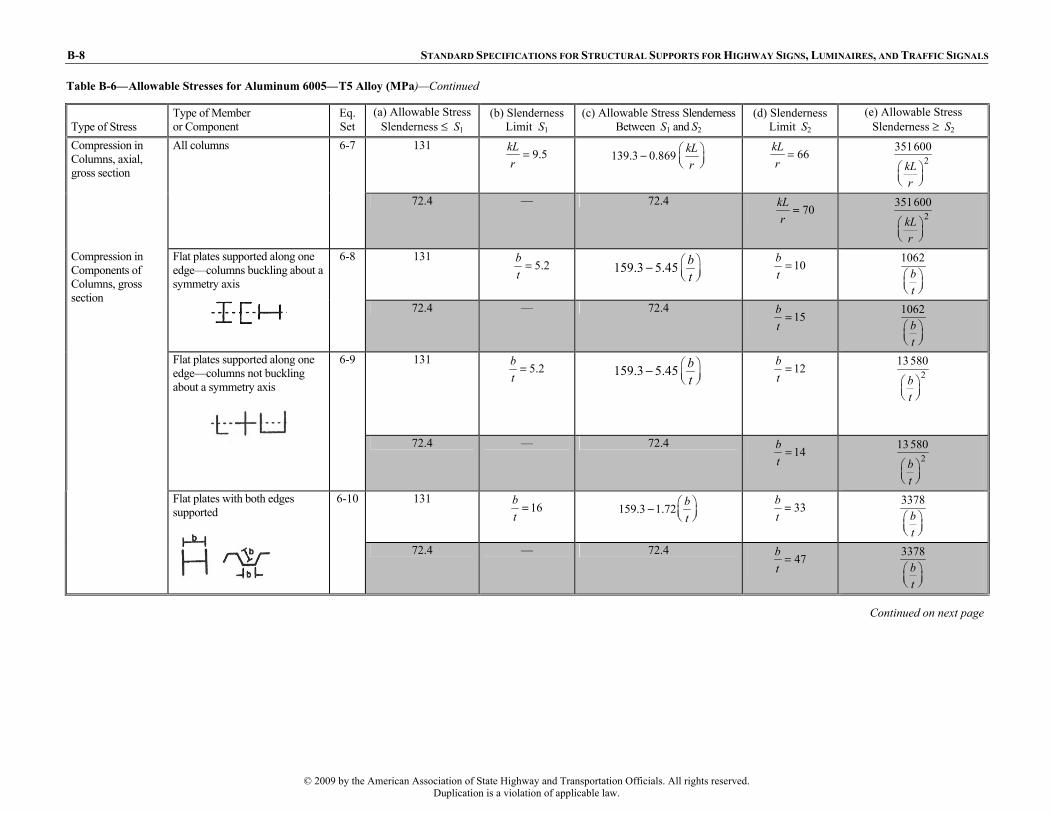
B-8 STANDARD SPECIFICATIONS FOR STRUCTURAL SUPPORTS FOR HIGHWAY SIGNS, LUMINAIRES, AND TRAFFIC SIGNALS
Table B-6—Allowable Stresses for Aluminum 6005—T5 Alloy (MPa)—Continued
Type of Stress Type of Member or Component
Eq. Set
(a) Allowable Stress Slenderness ≤ S1
(b) Slenderness Limit S1
(c) Allowable Stress Slenderness Between S1 and S2
(d) Slenderness Limit S2
(e) Allowable Stress Slenderness ≥ S2
131 9.5kL
r= 139.3 0.869 kL
r⎛ ⎞− ⎜ ⎟⎝ ⎠
66kLr
= 2351600
kLr
⎛ ⎞⎜ ⎟⎝ ⎠
Compression in Columns, axial, gross section
All columns
6-7
72.4 — 72.4 70kL
r= 2
351600
kLr
⎛ ⎞⎜ ⎟⎝ ⎠
131 5.2b
t= 159.3 5.45 b
t⎛ ⎞⎜ ⎟⎝ ⎠
− 10bt
= 1062bt
⎛ ⎞⎜ ⎟⎝ ⎠
Flat plates supported along one edge—columns buckling about a symmetry axis
6-8
72.4 — 72.4 15b
t= 1062
bt
⎛ ⎞⎜ ⎟⎝ ⎠
131 5.2b
t= 159.3 5.45 b
t⎛ ⎞⎜ ⎟⎝ ⎠
− 12bt
= 213 580
bt
⎛ ⎞⎜ ⎟⎝ ⎠
Compression in Components of Columns, gross section
Flat plates supported along one edge—columns not buckling about a symmetry axis
6-9
72.4 — 72.4 14b
t= 2
13 580
bt
⎛ ⎞⎜ ⎟⎝ ⎠
131 16b
t= 159.3 1.72 b
t⎛ ⎞− ⎜ ⎟⎝ ⎠
33bt
= 3378bt
⎛ ⎞⎜ ⎟⎝ ⎠
Flat plates with both edges supported
6-10
72.4 — 72.4 47b
t= 3378
bt
⎛ ⎞⎜ ⎟⎝ ⎠
Continued on next page
© 2009 by the American Association of State Highway and Transportation Officials. All rights reserved.Duplication is a violation of applicable law.

APPENDIX B: DESIGN AIDS B-9
ibn
Table B-6—Allowable Stresses for Aluminum 6005—T5 Alloy (MPa)—Continued
Continued on next page
Type of Stress Type of Member or Component
Eq. Set
(a) Allowable Stress Slenderness ≤ S1
(b) Slenderness Limit S1
(c) Allowable Stress Slenderness Between S1 and S2
(d) Slenderness Limit S2
(e) Allowable Stress Slenderness ≥ S2
131 16R
t= 153.1 5.52 R
t− 141R
t= 2
22 060
135
RR tt
⎛ ⎞⎜ ⎟⎛ ⎞ + ⎜ ⎟⎜ ⎟⎝ ⎠ ⎜ ⎟⎜ ⎟⎝ ⎠
Compression in Components of Columns, gross section (continued)
Curved plates supported on both edges, walls of round or oval tubesb
6-11
72.4 5.1R
t= 78.6 2.76 R
t− 340R
t= 2
22 060
135
RR tt
⎛ ⎞⎜ ⎟⎛ ⎞ + ⎜ ⎟⎜ ⎟⎝ ⎠ ⎜ ⎟⎜ ⎟⎝ ⎠
© 2009 by the American Association of State Highway and Transportation Officials. All rights reserved.Duplication is a violation of applicable law.

B-10 STANDARD SPECIFICATIONS FOR STRUCTURAL SUPPORTS FOR HIGHWAY SIGNS, LUMINAIRES, AND TRAFFIC SIGNALS
Table B-6—Allowable Stresses for Aluminum 6005—T5 Alloy (MPa)—Continued
Type of Stress Type of Member or Component
Eq. Set
(a) Allowable Stress Slenderness ≤ S1
(b) Slenderness Limit S1
(c) Allowable Stress Slenderness Between S1 and S2
(d) Slenderness Limit S2
(e) Allowable Stress Slenderness ≥ S2
145 23b
y
Lr
= 164.8 0.855 b
y
Lr
− 79b
y
Lr
= 2600 000
b
y
Lr
⎛ ⎞⎜ ⎟⎝ ⎠
Single web beams bent about strong axis
6-12
72.4 —
72.4 91b
y
Lr
= 2600 000
b
y
Lr
⎛ ⎞⎜ ⎟⎝ ⎠
172 28bR
t= 271.0 18.62 bR
t− 81bR
t=
same as Eq. 6-11 with R = Rb
Round or oval tubesb
6-13
82.7 53bR
t= 128.2 6.89 bR
t− 134bR
t=
same as Eq. 6-11 with R = Rb
193 13bLd
t d= 279.2 6.41 bLd
t d− 29bd L
t d= 2
78 600
bLdt d
⎛ ⎞⎛ ⎞⎜ ⎟ ⎜ ⎟⎝ ⎠ ⎝ ⎠
Solid rectangular and round section beams
6-14
93.1 — 93.1 29bd L
t d= 2
78 600
bLdt d
⎛ ⎞⎛ ⎞⎜ ⎟ ⎜ ⎟⎝ ⎠ ⎝ ⎠
145 146
0.5b c
y
L SI J
= 164.8 1.660.5
b c
y
L SI J
− 17000.5
b c
y
L SI J
= 165 500
0.5b c
y
L SI J
⎛ ⎞⎜ ⎟⎜ ⎟⎝ ⎠
Compression in Beams, extreme fiber, gross section
Rectangular tubes and box sections
6-15
72.4 — 72.4 2290
0.5b c
y
L SI J
= 165 500
0.5b c
y
L SI J
⎛ ⎞⎜ ⎟⎜ ⎟⎝ ⎠
Continued on next page
t
© 2009 by the American Association of State Highway and Transportation Officials. All rights reserved.Duplication is a violation of applicable law.

APPENDIX B: DESIGN AIDS B-11
Table B-6—Allowable Stresses for Aluminum 6005—T5 Alloy (MPa)—Continued
Type of Stress Type of Member or Component
Eq. Set
(a) Allowable Stress Slenderness
≤ S1 (b) Slenderness
Limit S1 (c) Allowable Stress Slenderness
Between S1 and S2 (d) Slenderness
Limit S2 (e) Allowable Stress
Slenderness ≥ S2 145
6.8bt
= 188.2 6.41bt
− 10bt
= 1262bt
⎛ ⎞⎜ ⎟⎝ ⎠
Flat plates supported on one edge
6-16
72.4 — 72.4 17b
t= 1262
bt
⎛ ⎞⎜ ⎟⎝ ⎠
145 22b
t= 188.2 2.0 b
t− 33b
t= 4000
bt
⎛ ⎞⎜ ⎟⎝ ⎠
Compression in Components of Beams, component under uniform compression, gross section
Flat plates with both edges supported
6-17
93.1 — 72.4 55b
t=
4000bt
⎛ ⎞⎜ ⎟⎝ ⎠
172 1.6bR
t= 180.6 6.48 bR
t− 141bR
t= 2
26 200
135
bb
RR tt
⎛ ⎞⎜ ⎟⎛ ⎞⎜ ⎟+⎜ ⎟⎜ ⎟⎝ ⎠⎜ ⎟⎝ ⎠
Curved plates supported on both edgesb
6-18
82.7 1.3bR
t= 85.5 2.41 bR
t− 340bR
t=
Same as nonwelded members
Continued on next page
© 2009 by the American Association of State Highway and Transportation Officials. All rights reserved.Duplication is a violation of applicable law.

B-12 STANDARD SPECIFICATIONS FOR STRUCTURAL SUPPORTS FOR HIGHWAY SIGNS, LUMINAIRES, AND TRAFFIC SIGNALS
Table B-6—Allowable Stresses for Aluminum 6005—T5 Alloy (MPa)—Continued
Type of Stress Type of Member or Component
Eq. Set
(a) Allowable Stress Slenderness
≤ S1 (b) Slenderness
Limit S1 (c) Allowable Stress Slenderness
Between S1 and S2 (d) Slenderness
Limit S2 (e) Allowable Stress
Slenderness ≥ S2 193
8.9bt
= 279.2 9.72 bt
− 19bt
= 233 780
bt
⎛ ⎞⎜ ⎟⎝ ⎠
Flat plates with compression edge free, tension edge supported
6-19
93.1 — 93.1 19b
t= 2
33 780
bt
⎛ ⎞⎜ ⎟⎝ ⎠
193 46h
t= 279.2 1.86 h
t− 75h
t= 10 480
ht
⎛ ⎞⎜ ⎟⎝ ⎠
Compression in Components of Beams, component under bending in own plane, gross section
Flat plate with both edges supported
6-20
93.1 — 93.1 113h
t= 10 480
ht
⎛ ⎞⎜ ⎟⎝ ⎠
83 36h
t= 107.6 0.683 h
t− 65h
t= 2
268 900
ht
⎛ ⎞⎜ ⎟⎝ ⎠
Shear in Webs, gross section
Unstiffened flat webs
6-21
41.4 — 41.4 81h
t= 2
268 900
ht
⎛ ⎞⎜ ⎟⎝ ⎠
© 2009 by the American Association of State Highway and Transportation Officials. All rights reserved.Duplication is a violation of applicable law.

APPENDIX B: DESIGN AIDS B-13
Table B-7—Allowable Stresses for Aluminum 6005—T5 Alloy (ksi)
Type of Stress Type of Member or Component
Eq. Set Allowable Stress
Tension, axial, net section
Any tension member
6-1 19 10.5 6005—T5 Extrusions Thickness ≤1.0 in.
Rectangular tubes, structural shapes bent around strong axis
6-2 19 10.5 White bars apply to nonwelded members and to welded members at locations farther than 1.0 in. from a weld.
Round or oval tubes
6-3 24 12 Shaded bars apply to within 1.0 in. of a weld.
Tension in Beams, extreme fiber, net section
Shapes bent about weak axis, bars, plates
6-4 28 13.5
On bolts
6-5 34 18 Bearing
On flat surfaces and on bolts in slotted holes
6-6 23 12
Notes: a See Articles 6.4.1, 6.4.2.1, and 6.4.4.1 for additional provisions regarding
allowable stresses. b For tubes with circumferential welds, R/t and Rb/t, as applicable, shall be ≤20,
except when the design meets the details and post-weld heat treatment requirements of Article 6.5.
c See Article 6.5 for additional provisions regarding allowable stresses in welded members.
d The article numbers and equations referenced in this table refer to Section 6, “Aluminum Design.”
Continued on next page
© 2009 by the American Association of State Highway and Transportation Officials. All rights reserved.Duplication is a violation of applicable law.

B-14 STANDARD SPECIFICATIONS FOR STRUCTURAL SUPPORTS FOR HIGHWAY SIGNS, LUMINAIRES, AND TRAFFIC SIGNALS
Table B-7—Allowable Stresses for Aluminum 6005—T5 Alloy (ksi)—Continued
Type of Stress Type of Member or Component
Eq. Set
(a) Allowable Stress
Slenderness ≤ S1 (b) Slenderness Limit S1
(c) Allowable Stress Slenderness Between
S1 and S2 (d) Slenderness Limit S2 (e) Allowable Stress
Slenderness ≥ S2 19
9.5kLr
= 20.2 0.126 kLr
⎛ ⎞− ⎜ ⎟⎝ ⎠ 66kL
r= 2
51000
kLr
⎛ ⎞⎜ ⎟⎝ ⎠
Compression in Columns, axial, gross section
All columns
6-7
10.5 — 10.5 70kL
r= 2
51000
kLr
⎛ ⎞⎜ ⎟⎝ ⎠
19 5.2b
t= 23.1 0.79 b
t⎛ ⎞− ⎜ ⎟⎝ ⎠
10bt
= 154bt
⎛ ⎞⎜ ⎟⎝ ⎠
Flat plates supported along one edge—columns buckling about a symmetry axis
6-8
10.5 — 10.5 15b
t= 154
bt
⎛ ⎞⎜ ⎟⎝ ⎠
19 5.2b
t= 23.1 0.79 b
t⎛ ⎞− ⎜ ⎟⎝ ⎠
12bt
= 21970
bt
⎛ ⎞⎜ ⎟⎝ ⎠
Flat plates supported along one edge—columns not buckling about a symmetry axis
6-9
10.5 — 10.5
14bt
= 21970
bt
⎛ ⎞⎜ ⎟⎝ ⎠
19 16b
t= 23.1 0.25 b
t⎛ ⎞− ⎜ ⎟⎝ ⎠
33bt
= 490bt
⎛ ⎞⎜ ⎟⎝ ⎠
Compression in Components of Columns, gross section
Flat plates with both edges supported
6-10
10.5 — 10.5 47b
t= 490
bt
⎛ ⎞⎜ ⎟⎝ ⎠
Continued on next page
© 2009 by the American Association of State Highway and Transportation Officials. All rights reserved.Duplication is a violation of applicable law.

APPENDIX B: DESIGN AIDS B-15
Table B-7—Allowable Stresses for Aluminum 6005—T5 Alloy (ksi)—Continued
Type of Stress Type of Member or Component
Eq. Set
(a) Allowable Stress
Slenderness ≤ S1 (b) Slenderness Limit S1
(c) Allowable Stress Slenderness Between
S1 and S2 (d) Slenderness Limit S2 (e) Allowable Stress
Slenderness ≥ S2 19
16Rt
= 22.2 0.80 Rt
− 141Rt
= 23200
135
RR tt
⎛ ⎞⎜ ⎟⎛ ⎞ +⎜ ⎟⎜ ⎟⎝ ⎠ ⎜ ⎟⎜ ⎟⎝ ⎠
Compression in Components of Columns, gross section
Curved plates supported on both edges, walls of round or oval tubesb
6-11
10.5 5.1R
t= 11.4 0.40 R
t− 340R
t= 2
3200
135
RR tt
⎛ ⎞⎜ ⎟⎛ ⎞ +⎜ ⎟⎜ ⎟⎝ ⎠ ⎜ ⎟⎜ ⎟⎝ ⎠
Continued on next page
© 2009 by the American Association of State Highway and Transportation Officials. All rights reserved.Duplication is a violation of applicable law.

B-16 STANDARD SPECIFICATIONS FOR STRUCTURAL SUPPORTS FOR HIGHWAY SIGNS, LUMINAIRES, AND TRAFFIC SIGNALS
Table B-7—Allowable Stresses for Aluminum 6005—T5 Alloy (ksi)—Continued
Type of Stress Type of Member or Component
Eq. Set
(a) Allowable Stress
Slenderness ≤ S1 (b) Slenderness Limit S1
(c) Allowable Stress Slenderness Between
S1 and S2 (d) Slenderness Limit S2
(e) Allowable Stress Slenderness ≥ S2
21 23b
y
Lr
= 23.9 0.124 b
y
Lr
− 79b
y
Lr
= 287 000
b
y
Lr
⎛ ⎞⎜ ⎟⎝ ⎠
Single web beams bent about strong axis
6-12
10.5 — 10.5 91b
y
Lr
= 287 000
b
y
Lr
⎛ ⎞⎜ ⎟⎝ ⎠
25 28bR
t= 39.3 2.70 bR
t− 81bR
t=
Same as Eq. 6-11 with R = Rb
Round or oval tubesb
6-13
12 53bR
t= 18.6 1.00 bR
t− 134bR
t=
Same as Eq. 6-11 with R = Rb
28 13bLd
t d= 40.5 0.93 bLd
t d− 29bLd
t d= 2
11400
bLdt d
⎛ ⎞⎛ ⎞⎜ ⎟ ⎜ ⎟⎝ ⎠ ⎝ ⎠
Solid rectangular and round section beams
6-14
13.5 — 13.5 29bLd
t d= 2
11400
bLdt d
⎛ ⎞⎛ ⎞⎜ ⎟ ⎜ ⎟⎝ ⎠ ⎝ ⎠
21 146
0.5b c
y
L SI J
= 23.9 0.240.5
b c
y
L SI J
− 17000.5
b c
y
L SI J
= 24 000
0.5b c
y
L SI J
⎛ ⎞⎜ ⎟⎜ ⎟⎝ ⎠
Compression in Beams, extreme fiber, gross section
Rectangular tubes and box sections
6-15
10.5 — 10.5 2290
0.5b c
y
L SI J
= 24 000
0.5b c
y
L SI J
⎛ ⎞⎜ ⎟⎜ ⎟⎝ ⎠
Continued on next page
t
© 2009 by the American Association of State Highway and Transportation Officials. All rights reserved.Duplication is a violation of applicable law.

APPENDIX B: DESIGN AIDS B-17
Table B-7—Allowable Stresses for Aluminum 6005—T5 Alloy (ksi)—Continued
Type of Stress Type of Member or Component
Eq. Set
(a) Allowable Stress
Slenderness ≤ S1 (b) Slenderness Limit S1
(c) Allowable Stress Slenderness Between S1 and
S2 (d) Slenderness Limit S2 (e) Allowable Stress
Slenderness ≥ S2 21
6.8bt
= 27.3 0.93bt
− 10bt
= 183bt
⎛ ⎞⎜ ⎟⎝ ⎠
Flat plates supported on one edge
6-16
10.5 — 10.5 17b
t= 183
bt
⎛ ⎞⎜ ⎟⎝ ⎠
21 22b
t= 27.3 0.29 b
t− 33b
t= 580
bt
⎛ ⎞⎜ ⎟⎝ ⎠
Flat plates with both edges supported
6-17
13.5 — 10.5 55b
t= 580
bt
⎛ ⎞⎜ ⎟⎝ ⎠
25 1.6bR
t= 26.2 0.94 bR
t− 141bR
t= 2
3800
135
bb
RR tt
⎛ ⎞⎜ ⎟⎛ ⎞ +⎜ ⎟⎜ ⎟⎝ ⎠ ⎜ ⎟⎜ ⎟⎝ ⎠
Compression in Components of Beams, component under uniform compression, gross section
Curved plates supported on both edgesb
6-18
12 1.3bR
t= 12.4 0.35 bR
t− 340bR
t=
Same as nonwelded members
Continued on next page
© 2009 by the American Association of State Highway and Transportation Officials. All rights reserved.Duplication is a violation of applicable law.

B-18 STANDARD SPECIFICATIONS FOR STRUCTURAL SUPPORTS FOR HIGHWAY SIGNS, LUMINAIRES, AND TRAFFIC SIGNALS
Table B-7—Allowable Stresses for Aluminum 6005—T5 Alloy (ksi)—Continued
Type of Stress Type of Member or Component
Eq. Set
(a) Allowable Stress
Slenderness ≤ S1 (b) Slenderness Limit S1
(c) Allowable Stress Slenderness Between
S1 and S2 (d) Slenderness Limit S2 (e) Allowable Stress
Slenderness ≥ S2 28
8.9bt
= 40.5 1.41bt
− 19bt
= 24900
bt
⎛ ⎞⎜ ⎟⎝ ⎠
Flat plates with compression edge free, tension edge supported
6-19
13.5 — 13.5 19b
t= 2
4900
bt
⎛ ⎞⎜ ⎟⎝ ⎠
28 46h
t= 40.5 0.27 h
t− 75h
t= 1520
ht
⎛ ⎞⎜ ⎟⎝ ⎠
Compression in Components of Beams, component under bending in own plane, gross section
Flat plate with both edges supported
6-20
13.5 — 13.5 113h
t= 1520
ht
⎛ ⎞⎜ ⎟⎝ ⎠
12 36h
t= 15.6 0.099 h
t− 65h
t= 2
39 000
ht
⎛ ⎞⎜ ⎟⎝ ⎠
Shear in Webs, gross section
Unstiffened flat webs
6-21
6 — 6 81h
t= 2
39 000
ht
⎛ ⎞⎜ ⎟⎝ ⎠
© 2009 by the American Association of State Highway and Transportation Officials. All rights reserved.Duplication is a violation of applicable law.

APPENDIX B: DESIGN AIDS B-19
Table B-8—Allowable Stresses for Aluminum 6061—T6 Alloy (MPa)
Type of Stress Type of Member or Component
Eq. Set Allowable Stress
Tension, axial, net section
Any tension member
6-1 131 75.8e 6061—T6 Extrusions Up Through 25 mm, Sheet and Plate, Standard Structural Shapes, Drawn Tube, Rolled Rod and Bar
Rectangular tubes, structural shapes bent around strong axis
6-2 131 75.8e White bars apply to nonwelded members and to welded members at locations farther than 25 mm from a weld
Round or oval tubes
6-3 165 93e Shaded bars apply to within 25 mm of a weld
Tension in Beams, extreme fiber, net section
Shapes bent about weak axis, bars, plates
6-4 193 110e
On bolts
6-5 234 124e Bearing
On flat surfaces and on bolts in slotted holes
6-6 159 82.7e
Notes: a See Articles 6.4.1, 6.4.2.1, and 6.4.4.1 for additional provisions regarding
allowable stresses. b For tubes with circumferential welds, R/t and Rb/t, as applicable, shall be ≤20,
except when the design meets the details and post-weld heat treatment requirements of Article 6.5
c See Article 6.5 for additional provision regarding allowable stresses in welded members.
d The article numbers and equations referenced in this table refer to Section 6, “Aluminum Design.”
e Values when welded with 5183, 5356, or 5556 alloy filler wire, regardless of thickness. Values also apply to thicknesses ≤9.5 mm when welded with 4043 alloy filler wire; for greater thicknesses multiply allowable tensile stresses by 0.8 and allowable compressive and shear stresses by 0.75.
f For all thicknesses with filler alloys 5183, 5356 or 5556; and for thicknesses ≤9.5 mm for 4043 filler alloy.
Continued on next page
© 2009 by the American Association of State Highway and Transportation Officials. All rights reserved.Duplication is a violation of applicable law.

B-20 STANDARD SPECIFICATIONS FOR STRUCTURAL SUPPORTS FOR HIGHWAY SIGNS, LUMINAIRES, AND TRAFFIC SIGNALS
Continued on next page
Table B-8—Allowable Stresses for Aluminum 6061—T6 Alloy (MPa)—Continued
Type of Stress Type of Member or Component
Eq. Set
(a) Allowable Stress
Slenderness ≤ S1 (b) Slenderness
Limit S1
(c) Allowable Stress Slenderness Between
S1 and S2 (d) Slenderness Limit
S2 (e) Allowable Stress
Slenderness ≥ S2 Compression in Columns, axial, gross section
All columns 6-7 131 9.5kL
r= 139.3 0.869 kL
r⎛ ⎞− ⎜ ⎟⎝ ⎠
66kLr
= 2351600
kLr
⎛ ⎞⎜ ⎟⎝ ⎠
82.7e — 82.7e 65kLr
= f 2
351600
kLr
⎛ ⎞⎜ ⎟⎝ ⎠
Compression in Components of Columns, gross section
Flat plates supported along one edge—columns buckling about a symmetry axis
6-8 131 5.2b
t= 159.3 5.45 b
t⎛ ⎞− ⎜ ⎟⎝ ⎠
10bt
= 1062bt
⎛ ⎞⎜ ⎟⎝ ⎠
82.7e — 82.7e 13bt
= f
1062bt
⎛ ⎞⎜ ⎟⎝ ⎠
Flat plates supported along one edge—columns not buckling about a symmetry axis
6-9 131 5.2b
t= 159.3 5.45 b
t⎛ ⎞− ⎜ ⎟⎝ ⎠
12bt
= 213580
bt
⎛ ⎞⎜ ⎟⎝ ⎠
82.7e — 82.7e 13bt
= f 2
13580
bt
⎛ ⎞⎜ ⎟⎝ ⎠
Flat plates with both edges supported
6-10 131 16b
t= 159.3 1.72 b
t⎛ ⎞− ⎜ ⎟⎝ ⎠
33bt
= 3378bt
⎛ ⎞⎜ ⎟⎝ ⎠
82.7e — 82.7e 41bt
= f
3378bt
⎛ ⎞⎜ ⎟⎝ ⎠
© 2009 by the American Association of State Highway and Transportation Officials. All rights reserved.Duplication is a violation of applicable law.

APPENDIX B: DESIGN AIDS B-21
Table B-8—Allowable Stresses for Aluminum 6061—T6 Alloy (MPa)—Continued
Type of Stress Type of Member or Component
Eq. Set
(a) Allowable Stress
Slenderness ≤ S1 (b) Slenderness
Limit S1
(c) Allowable Stress Slenderness Between
S1 and S2 (d) Slenderness Limit
S2 (e) Allowable Stress
Slenderness ≥ S2 131
16Rt
= 153.1 5.52 Rt
− 141Rt
= 222 060
135
RR tt
⎛ ⎞⎜ ⎟⎛ ⎞ +⎜ ⎟⎜ ⎟⎝ ⎠ ⎜ ⎟⎜ ⎟⎝ ⎠
Compression in Components of Columns, gross section (continued)
Curved plates supported on both edges, walls of round or oval tubesb
6-11
82.7e 9.0R
t= 93.1 3.45 R
t− 290R
t= 2
22 060
135
RR tt
⎛ ⎞⎜ ⎟⎛ ⎞ +⎜ ⎟⎜ ⎟⎝ ⎠ ⎜ ⎟⎜ ⎟⎝ ⎠
Continued on next page
© 2009 by the American Association of State Highway and Transportation Officials. All rights reserved.Duplication is a violation of applicable law.

B-22 STANDARD SPECIFICATIONS FOR STRUCTURAL SUPPORTS FOR HIGHWAY SIGNS, LUMINAIRES, AND TRAFFIC SIGNALS
Table B-8—Allowable Stresses for Aluminum 6061—T6 Alloy (MPa)—Continued
Type of Stress Type of Member or Component
Eq. Set
(a) Allowable Stress
Slenderness ≤ S1 (b) Slenderness
Limit S1
(c) Allowable Stress Slenderness Between
S1 and S2 (d) Slenderness Limit S2
(e) Allowable Stress Slenderness ≥ S2
6-12 145 23b
y
Lr
= 164.8 0.855 b
y
Lr
− 79b
y
Lr
= 2600 000
b
y
Lr
⎛ ⎞⎜ ⎟⎝ ⎠
Single web beams bent about strong axis
82.7e — 82.7e
85b
y
Lr
= f
2600 000
b
y
Lr
⎛ ⎞⎜ ⎟⎝ ⎠
6-13 172 28bR
t= 270.6 18.61 bR
t− 81bR
t=
Same as Eq. 6-11 with R = Rb
Round or oval tubesb
96.5e 51bR
t= 164.8 9.58 bR
t− 137bR
t=
Same as Eq. 6-11 with R = Rb
6-14 193 13bLd
t d= 279.2 6.41 bLd
t d− 29bLd
t d= 2
78 600
bLdt d
⎛ ⎞⎛ ⎞⎜ ⎟ ⎜ ⎟⎝ ⎠ ⎝ ⎠
Solid rectangular and round section beams
110e
26bLdt d
= 279.2 6.41 bLdt d
− 29bLdt d
= 278 600
bLdt d
⎛ ⎞⎛ ⎞⎜ ⎟ ⎜ ⎟⎝ ⎠ ⎝ ⎠
6-15 145 146
0.5b c
y
L SI J
= 164.8 1.660.5
b c
y
L SI J
− 17000.5
b c
y
L SI J
= 165 500
0.5b c
y
L SI J
⎛ ⎞⎜ ⎟⎜ ⎟⎝ ⎠
Compression in Beams, extreme fiber, gross section
Rectangular tubes and box sections
82.7e — 82.7e 20000.5
b c
y
L SI J
= f
165 500
0.5b c
y
L SI J
⎛ ⎞⎜ ⎟⎜ ⎟⎝ ⎠
Continued on next page
t
© 2009 by the American Association of State Highway and Transportation Officials. All rights reserved.Duplication is a violation of applicable law.

APPENDIX B: DESIGN AIDS B-23
Table B-8—Allowable Stresses for Aluminum 6061—T6 Alloy (MPa)—Continued
Type of Stress Type of Member or Component
Eq. Set
(a) Allowable Stress
Slenderness ≤ S1 (b) Slenderness
Limit S1
(c) Allowable Stress Slenderness Between
S1 and S2 (d) Slenderness Limit S2
(e) Allowable Stress Slenderness ≥ S2
6-16 145 6.8b
t= 188.2 6.41b
t− 10b
t=
1255bt
⎛ ⎞⎜ ⎟⎝ ⎠
Flat plates supported on one edge
82.7e — 82.7e
15bt
= f
1255bt
⎛ ⎞⎜ ⎟⎝ ⎠
6-17 145 22b
t= 188.2 2.0 b
t− 33b
t=
4000bt
⎛ ⎞⎜ ⎟⎝ ⎠
Flat plates with both edges supported
82.7e — 82.7e 48b
t= f
4000
bt
⎛ ⎞⎜ ⎟⎝ ⎠
6-18 172 1.6bR
t= 180.6 6.48 bR
t− 141bR
t= 2
26 200
135
bb
RR tt
⎛ ⎞⎜ ⎟⎛ ⎞ +⎜ ⎟⎜ ⎟⎝ ⎠ ⎜ ⎟⎜ ⎟⎝ ⎠
Compression in Components of Beams, component under uniform compression, gross section
Curved plates supported on both edgesb
96.5e 2.5bR
t= 101.4 3.03 bR
t− 290bR
t=
Same as nonwelded members
Continued on next page
© 2009 by the American Association of State Highway and Transportation Officials. All rights reserved.Duplication is a violation of applicable law.

B-24 STANDARD SPECIFICATIONS FOR STRUCTURAL SUPPORTS FOR HIGHWAY SIGNS, LUMINAIRES, AND TRAFFIC SIGNALS
Table B-8—Allowable Stresses for Aluminum 6061—T6 Alloy (MPa)—Continued
Type of Stress Type of Member or Component
Eq. Set
(a) Allowable Stress
Slenderness ≤ S1 (b) Slenderness
Limit S1
(c) Allowable Stress Slenderness Between
S1 and S2 (d) Slenderness Limit S2
(e) Allowable Stress Slenderness ≥ S2
6-19 193 8.9b
t= 279.2 9.72 b
t− 19b
t= 2
33 780
bt
⎛ ⎞⎜ ⎟⎝ ⎠
Flat plates with compression edge free, tension edge supported
110e
17bt
= 279.2 9.72 bt
− 19bt
= 233 780
bt
⎛ ⎞⎜ ⎟⎝ ⎠
6-20 193 46h
t= 279.2 1.86 b
t− 75h
t= 10 480
ht
⎛ ⎞⎜ ⎟⎝ ⎠
Compression in Components of Beams, component under bending in own plane, gross section
Flat plate with both edges supported
110e — 110e 95ht
= f
10 480ht
⎛ ⎞⎜ ⎟⎝ ⎠
6-21 83 36h
t= 107.6 0.683 h
t− 65h
t= 2
268 900
ht
⎛ ⎞⎜ ⎟⎝ ⎠
Shear in Webs, gross section
Unstiffened flat webs
51.7e — 51.7e 72h
t= f
2268 900
ht
⎛ ⎞⎜ ⎟⎝ ⎠
© 2009 by the American Association of State Highway and Transportation Officials. All rights reserved.Duplication is a violation of applicable law.

APPENDIX B: DESIGN AIDS B-25
Table B-9—Allowable Stresses for Aluminum 6061—T6 Alloy (ksi)
Type of Stress Type of Member or Component
Eq. Set Allowable Stress
Tension, axial, net section
Any tension member
6-1 19 11e
Rectangular tubes, structural shapes bent around strong axis
6-2 19 11e
Round or oval tubes
6-3 24 13.5e
6061—T6 Extrusions Up Through 1.0 in., Sheet and Plate, Standard Structural Shapes, Drawn Tube, Rolled Rod and Bar White bars apply to nonwelded members and to welded members at locations farther than 1.0 in. from a weld Shaded bars apply to within 1.0 in. of a weld
Tension in Beams, extreme fiber, net section
Shapes bent about weak axis, bars, plates
6-4 28 16e
On bolts
6-5 34 18e Bearing
On flat surfaces and on bolts in slotted holes
6-6 23 12e
Notes: a See Articles 6.4.1, 6.4.2.1, and 6.4.4.1 for additional provisions regarding
allowable stresses. b For tubes with circumferential welds, R/t and Rb/t, as applicable, shall be
≤20, except when the design meets the details and post-weld heat treatment requirements of Article 6.5.
c See Article 6.5 for additional provisions regarding allowable stresses in welded members.
d The article numbers and equations referenced in this table refer to Section 6, “Aluminum Design.”
e Values when welded with 5183, 5356, or 5556 alloy filler wire, regardless of thickness. Values also apply to thicknesses ≤0.375 in. when welded with 4043 alloy filler wire; for greater thicknesses multiply allowable tensile stresses by 0.8 and allowable compressive and shear stresses by 0.75.
f For all thicknesses with filler alloys 5183, 5356 or 5556 and for thicknesses ≤0.375 in. for 4043 filler alloy.
Continued on next page
© 2009 by the American Association of State Highway and Transportation Officials. All rights reserved.Duplication is a violation of applicable law.

B-26 STANDARD SPECIFICATIONS FOR STRUCTURAL SUPPORTS FOR HIGHWAY SIGNS, LUMINAIRES, AND TRAFFIC SIGNALS
Table B-9—Allowable Stresses for Aluminum 6061—T6 Alloy (ksi)—Continued
Type of Stress Type of Member or Component
Eq. Set
(a) Allowable Stress
Slenderness ≤ S1 (b) Slenderness Limit S1
(c) Allowable Stress Slenderness Between
S1 and S2 (d) Slenderness Limit S2 (e) Allowable Stress
Slenderness ≥ S2 19
9.5kLr
= 20.2 0.126 kLr
⎛ ⎞− ⎜ ⎟⎝ ⎠ 66kL
r= 2
51000
kLr
⎛ ⎞⎜ ⎟⎝ ⎠
Compression in Columns, axial, gross section
All columns
6-7
12e — 12e 65kLr
= f 2
51000
kLr
⎛ ⎞⎜ ⎟⎝ ⎠
19 5.2b
t= 23.1 0.79 b
t⎛ ⎞− ⎜ ⎟⎝ ⎠
10bt
= 154bt
⎛ ⎞⎜ ⎟⎝ ⎠
Flat plates supported along one edge—columns buckling about a symmetry axis
6-8
12e — 12e 13b
t= f
154
bt
⎛ ⎞⎜ ⎟⎝ ⎠
19 5.2b
t= 23.1 0.79 b
t⎛ ⎞− ⎜ ⎟⎝ ⎠
12bt
= 21970
bt
⎛ ⎞⎜ ⎟⎝ ⎠
Flat plates supported along one edge—columns not buckling about a symmetry axis
6-9
12e — 12e 13bt
= f 2
1970
bt
⎛ ⎞⎜ ⎟⎝ ⎠
19 16b
t= 23.1 0.25 b
t⎛ ⎞− ⎜ ⎟⎝ ⎠
33bt
= 490bt
⎛ ⎞⎜ ⎟⎝ ⎠
Compression in Components of Columns, gross section
Flat plates with both edges supported
6-10
12e — 12e 41bt
= f
490bt
⎛ ⎞⎜ ⎟⎝ ⎠
Continued on next page
© 2009 by the American Association of State Highway and Transportation Officials. All rights reserved.Duplication is a violation of applicable law.

APPENDIX B: DESIGN AIDS B-27
Table B-9—Allowable Stresses for Aluminum 6061—T6 Alloy (ksi)—Continued
Type of Stress Type of Member or Component
Eq. Set
(a) Allowable Stress
Slenderness ≤ S1 (b) Slenderness Limit S1
(c) Allowable Stress Slenderness Between
S1 and S2 (d) Slenderness Limit S2 (e) Allowable Stress
Slenderness ≥ S2 Compression in Components of Columns, gross section (continued)
Curved plates supported on both edges, walls of round or oval tubesb
6-11 19 16R
t= 22.2 0.80 R
t− 141R
t= 2
3200
135
RR tt
⎛ ⎞⎜ ⎟⎛ ⎞ +⎜ ⎟⎜ ⎟⎝ ⎠ ⎜ ⎟⎜ ⎟⎝ ⎠
12e 9.0R
t= 13.5 0.50 R
t− 290R
t= 2
3200
135
RR tt
⎛ ⎞⎜ ⎟⎛ ⎞ +⎜ ⎟⎜ ⎟⎝ ⎠ ⎜ ⎟⎜ ⎟⎝ ⎠
Continued on next page
© 2009 by the American Association of State Highway and Transportation Officials. All rights reserved.Duplication is a violation of applicable law.

B-28 STANDARD SPECIFICATIONS FOR STRUCTURAL SUPPORTS FOR HIGHWAY SIGNS, LUMINAIRES, AND TRAFFIC SIGNALS
Table B-9—Allowable Stresses for Aluminum 6061—T6 Alloy (ksi)—Continued
Type of Stress Type of Member or Component
Eq. Set
(a) Allowable Stress
Slenderness ≤ S1 (b) Slenderness Limit S1
(c) Allowable Stress Slenderness Between
S1 and S2 (d) Slenderness Limit S2 (e) Allowable Stress
Slenderness ≥ S2 Compression in Beams, extreme fiber, gross section
Single web beams bent about strong axis
6-12 21 23b
y
Lr
= 23.9 0.124 b
y
Lr
− 79b
y
Lr
= 287 000
b
y
Lr
⎛ ⎞⎜ ⎟⎝ ⎠
12e — 12e 85b
y
Lr
= f 2
87 000
b
y
Lr
⎛ ⎞⎜ ⎟⎝ ⎠
Round or oval tubesb
6-13 25 28bRt
= 39.3 2.70 bRt
− 81bRt
= Same as Eq. 6-11 with
R = Rb
14e 51bRt
= 23.9 1.39 bRt
− 137bRt
= Same as Eq. 6-11 with
R = Rb
Solid rectangular and round section beams
6-14 28 13bLdt d
= 40.5 0.93 bLdt d
− 29bLdt d
= 211400
bLdt d
⎛ ⎞⎛ ⎞⎜ ⎟ ⎜ ⎟⎝ ⎠ ⎝ ⎠
16e 26bLdt d
= 40.5 0.93 bLdt d
− 29bLdt d
= 211400
bLdt d
⎛ ⎞⎛ ⎞⎜ ⎟ ⎜ ⎟⎝ ⎠ ⎝ ⎠
Rectangular tubes and box sections
6-15 21 146
0.5b c
y
L SI J
= 23.9 0.240.5
b c
y
L SI J
− 17000.5
b c
y
L SI J
= 24 000
0.5b c
y
L SI J
⎛ ⎞⎜ ⎟⎜ ⎟⎝ ⎠
12e — 12e 20000.5
b c
y
L SI J
= f
24 000
0.5b c
y
L SI J
⎛ ⎞⎜ ⎟⎜ ⎟⎝ ⎠
Continued on next page
t
© 2009 by the American Association of State Highway and Transportation Officials. All rights reserved.Duplication is a violation of applicable law.

APPENDIX B: DESIGN AIDS B-29
Table B-9—Allowable Stresses for Aluminum 6061—T6 Alloy (ksi)—Continued
Type of Stress Type of Member or Component
Eq. Set
(a) Allowable Stress
Slenderness ≤S1 (b) Slenderness Limit S1
(c) Allowable Stress Slenderness Between
S1and S2 (d) Slenderness Limit S2
(e) Allowable Stress Slenderness ≥ S2
21 6.8b
t= 27.3 0.93b
t− 10b
t= 182
bt
⎛ ⎞⎜ ⎟⎝ ⎠
Flat plates supported on one edge
6-16
12e — 12e 15b
t=
f 182
bt
⎛ ⎞⎜ ⎟⎝ ⎠
21 22b
t= 27.3 0.29 b
t− 33b
t= 580
bt
⎛ ⎞⎜ ⎟⎝ ⎠
Flat plates with both edges supported
6-17
12e — 12e 48bt
= f
580bt
⎛ ⎞⎜ ⎟⎝ ⎠
25 1.6bR
t= 26.2 0.94 bR
t− 141bR
t= 2
3800
135
bb
RR tt
⎛ ⎞⎜ ⎟⎛ ⎞⎜ ⎟+⎜ ⎟⎜ ⎟⎝ ⎠⎜ ⎟⎝ ⎠
Compression in Components of Beams, component under uniform compression, gross section
Curved plates supported on both edgesb
6-18
14e 2.5bR
t= 1.47 0.44 bR
t− 290bR
t=
Same as nonwelded members
Continued on next page
© 2009 by the American Association of State Highway and Transportation Officials. All rights reserved.Duplication is a violation of applicable law.

B-30 STANDARD SPECIFICATIONS FOR STRUCTURAL SUPPORTS FOR HIGHWAY SIGNS, LUMINAIRES, AND TRAFFIC SIGNALS
Table B-9—Allowable Stresses for Aluminum 6061—T6 Alloy (ksi)—Continued
Type of Stress Type of Member or Component
Eq. Set
(a) Allowable Stress
Slenderness ≤S1 (b) Slenderness Limit S1
(c) Allowable Stress Slenderness Between
S1and S2 (d) Slenderness Limit S2
(e) Allowable Stress Slenderness ≥ S2
28 8.9bt
= 40.5 1.41bt
− 19bt
= 24900
bt
⎛ ⎞⎜ ⎟⎝ ⎠
Flat plates with compression edge free, tension edge supported
6-19
16e 17bt
= 40.5 1.41bt
− 19bt
= 24900
bt
⎛ ⎞⎜ ⎟⎝ ⎠
28 46h
t= 40.5 0.27 h
t− 75h
t= 1520
ht
⎛ ⎞⎜ ⎟⎝ ⎠
Compression in Components of Beams, component under bending in own plane, gross section
Flat plate with both edges supported
6-20
16e — 16e 95ht
=f
1520
ht
⎛ ⎞⎜ ⎟⎝ ⎠
12 36ht
= 15.6 0.099 ht
− 65ht
= 239 000
ht
⎛ ⎞⎜ ⎟⎝ ⎠
Shear in Webs, gross section
Unstiffened flat webs
6-21
7.5e — 7.5e 72ht
= f 2
39 000
ht
⎛ ⎞⎜ ⎟⎝ ⎠
© 2009 by the American Association of State Highway and Transportation Officials. All rights reserved.Duplication is a violation of applicable law.

APPENDIX B: DESIGN AIDS B-31
Table B-10—Allowable Stresses for Aluminum 6063—T6 Alloy (MPa)
Type of Stress Type of Member or Component
Eq. Set Allowable Stress
Tension, axial, net section
Any tension member
6-1 103 44.8 6063—T6 Extrusions, Pipe
Rectangular tubes, structural shapes bent around strong axis
6-2 103 44.8 White bars apply to nonwelded members and to welded members at locations farther than 25 mm from a weld
Round or oval tubes
6-3 124 55.2 Shaded bars apply to within 25 mm of a weld
Tension in Beams, extreme fiber, net section
Shapes bent about weak axis, bars, plates
6-4 138 58.6
Bearing On bolts 6-5 165 93.1 On flat surfaces and on bolts in
slotted holes
6-6 110 62.1
Notes: a See Articles 6.4.1, 6.4.2.1, and 6.4.4.1 for additional provisions regarding
allowable stresses. b For tubes with circumferential welds, R/t and Rb/t, as applicable, shall be
≤20, except when the design meets the details and post-weld heat treatment requirements of Article 6.5
c See Article 6.5 for additional provisions regarding allowable stresses in welded members.
d The article numbers and equations referenced in this table refer to Section 6, “Aluminum Design.”
Continued on next page
© 2009 by the American Association of State Highway and Transportation Officials. All rights reserved.Duplication is a violation of applicable law.

B-32 STANDARD SPECIFICATIONS FOR STRUCTURAL SUPPORTS FOR HIGHWAY SIGNS, LUMINAIRES, AND TRAFFIC SIGNALS
Table B-10—Allowable Stresses for Aluminum 6063—T6 Alloy (MPa)—Continued
Type of Stress Type of Member or Component
Eq. Set
(a) Allowable Stress
Slenderness ≤ S1
(b) Slenderness Limit S1
(c) Allowable Stress Slenderness Between
S1 and S2 (d) Slenderness Limit
S2 (e) Allowable Stress
Slenderness ≥ S2 93.1
9.5kLr
= 97.9 0.510 kLr
⎛ ⎞− ⎜ ⎟⎝ ⎠ 78kL
r= 2
351600
kLr
⎛ ⎞⎜ ⎟⎝ ⎠
Compression in Columns, axial, gross section
All columns
6-7
44.8 — 44.8 89kL
r= 2
351600
kLr
⎛ ⎞⎜ ⎟⎝ ⎠
93.1 5.7b
t= 111.0 3.17 b
t⎛ ⎞− ⎜ ⎟⎝ ⎠
12bt
= 889bt
⎛ ⎞⎜ ⎟⎝ ⎠
Flat plates supported along one edge—columns buckling about a symmetry axis
6-8
44.8 — 44.8 20b
t= 889
bt
⎛ ⎞⎜ ⎟⎝ ⎠
93.1 5.7b
t= 111.0 3.17 b
t⎛ ⎞− ⎜ ⎟⎝ ⎠
15bt
= 213580
bt
⎛ ⎞⎜ ⎟⎝ ⎠
Flat plates supported along one edge—columns not buckling about a symmetry axis
6-9
44.8 — 44.8 17b
t= 2
13580
bt
⎛ ⎞⎜ ⎟⎝ ⎠
6-10 93.1 18b
t= 111.0 1.0 b
t⎛ ⎞− ⎜ ⎟⎝ ⎠
39bt
= 2827bt
⎛ ⎞⎜ ⎟⎝ ⎠
Compression in Components of Columns, gross section
Flat plates with both edges supported
44.8 — 44.8 63b
t= 2827
bt
⎛ ⎞⎜ ⎟⎝ ⎠
Continued on next page
© 2009 by the American Association of State Highway and Transportation Officials. All rights reserved.Duplication is a violation of applicable law.

APPENDIX B: DESIGN AIDS B-33
Table B-10—Allowable Stresses for Aluminum 6063—T6 Alloy (MPa)—Continued
Type of Stress Type of Member or Component
Eq. Set
(a) Allowable Stress
Slenderness ≤ S1
(b) Slenderness Limit S1
(c) Allowable Stress Slenderness Between
S1 and S2 (d) Slenderness Limit
S2 (e) Allowable Stress
Slenderness ≥ S2 6-11 93.1
18Rt
= 107.6 3.45 Rt
− 188Rt
= 222 060
135
RR tt
⎛ ⎞⎜ ⎟⎛ ⎞ +⎜ ⎟⎜ ⎟⎝ ⎠ ⎜ ⎟⎜ ⎟⎝ ⎠
Compression in Components of Columns, gross section (continued)
Curved plates supported on both edges, walls of round or oval tubesb
44.8
10Rt
= 49.6 1.52 Rt
− 510Rt
= 222 060
135
RR tt
⎛ ⎞⎜ ⎟⎛ ⎞ +⎜ ⎟⎜ ⎟⎝ ⎠ ⎜ ⎟⎜ ⎟⎝ ⎠
Continued on next page
© 2009 by the American Association of State Highway and Transportation Officials. All rights reserved.Duplication is a violation of applicable law.

B-34 STANDARD SPECIFICATIONS FOR STRUCTURAL SUPPORTS FOR HIGHWAY SIGNS, LUMINAIRES, AND TRAFFIC SIGNALS
Table B-10—Allowable Stresses for Aluminum 6063—T6 Alloy (MPa)—Continued
Type of Stress Type of Member or Component
Eq. Set
(a) Allowable Stress
Slenderness ≤ S1 (b) Slenderness Limit S1
(c) Allowable Stress Slenderness Between
S1 and S2 (d) Slenderness Limit S2 (e) Allowable Stress
Slenderness ≥ S2 103
23b
y
Lr
= 151.1 0.503 b
y
Lr
− 94b
y
Lr
= 2600 000
b
y
Lr
⎛ ⎞⎜ ⎟⎝ ⎠
Single web beams bent about strong axis
6-12
44.8 — 44.8 116b
y
Lr
= 2600 000
b
y
Lr
⎛ ⎞⎜ ⎟⎝ ⎠
124 33bR
t= 191.0 11.72 bR
t− 102bR
t=
Same as Eq. 6-11 with R = Rb
Round or oval tubesb
6-13
55.2 62bR
t= 88.3 4.21 bR
t− 206bR
t=
Same as Eq. 6-11 with R = Rb
138 15bLd
t d= 192.4 3.65 bLd
t d− 35bLd
t d= 2
78 600
bLdt d
⎛ ⎞⎛ ⎞⎜ ⎟ ⎜ ⎟⎝ ⎠ ⎝ ⎠
Solid rectangular and round section beams
6-14
58.6 — 58.6 37bLd
t d= 2
78 600
bLdt d
⎛ ⎞⎛ ⎞⎜ ⎟ ⎜ ⎟⎝ ⎠ ⎝ ⎠
103 145
0.5b c
y
L SI J
= 115.1 0.9720.5
b c
y
SLJI
−
23800.5
b c
y
L SI J
= 165 500
0.5b c
y
L SI J
⎛ ⎞⎜ ⎟⎜ ⎟⎝ ⎠
Compression in Beams, extreme fiber, gross section
Rectangular tubes and box sections
6-15
44.8 — 44.8 3690
0.5b c
y
L SI J
= 165 500
0.5b c
y
L SI J
⎛ ⎞⎜ ⎟⎜ ⎟⎝ ⎠
Continued on next page
t
© 2009 by the American Association of State Highway and Transportation Officials. All rights reserved.Duplication is a violation of applicable law.

APPENDIX B: DESIGN AIDS B-35
Table B-10—Allowable Stresses for Aluminum 6063—T6 Alloy (MPa)—Continued
Type of Stress Type of Member or Component
Eq. Set
(a) Allowable Stress
Slenderness ≤ S1 (b) Slenderness Limit S1
(c) Allowable Stress Slenderness Between
S1 and S2 (d) Slenderness Limit S2 (e) Allowable Stress
Slenderness ≥ S2 103
7.4bt
= 131.0 3.72 bt
− 12bt
= 1048bt
⎛ ⎞⎜ ⎟⎝ ⎠
Flat plates supported on one edge
6-16
44.8 — 44.8 23b
t= 1048
bt
⎛ ⎞⎜ ⎟⎝ ⎠
103 24b
t= 131.0 1.172 b
t− 39b
t= 3309
bt
⎛ ⎞⎜ ⎟⎝ ⎠
Flat plates with both edges supported
6-17
44.8 — 44.8 74b
t= 3309
bt
⎛ ⎞⎜ ⎟⎝ ⎠
124 0.7bR
t= 127.6 4.07 bR
t− 188bR
t= 2
26 200
135
bb
RR tt
⎛ ⎞⎜ ⎟⎛ ⎞ +⎜ ⎟⎜ ⎟⎝ ⎠ ⎜ ⎟⎜ ⎟⎝ ⎠
Compression in Components of Beams, component under uniform compression, gross section
Curved plates supported on both edgesb
6-18
55.2 0.3bR
t= 5.45 1.31 bR
t− 510bR
t=
Same as nonwelded members
Continued on next page
© 2009 by the American Association of State Highway and Transportation Officials. All rights reserved.Duplication is a violation of applicable law.

B-36 STANDARD SPECIFICATIONS FOR STRUCTURAL SUPPORTS FOR HIGHWAY SIGNS, LUMINAIRES, AND TRAFFIC SIGNALS
Table B-10—Allowable Stresses for Aluminum 6063—T6 Alloy (MPa)—Continued
Type of Stress Type of Member or Component
Eq. Set
(a) Allowable Stress
Slenderness ≤ S1 (b) Slenderness Limit S1
(c) Allowable Stress Slenderness Between
S1 and S2 (d) Slenderness Limit S2 (e) Allowable Stress
Slenderness ≥ S2 138
9.8bt
= 192.4 5.59 bt
− 23bt
= 233 780
bt
⎛ ⎞⎜ ⎟⎝ ⎠
Flat plates with compression edge free, tension edge supported
6-19
58.6 — 58.6 24b
t= 2
33 780
bt
⎛ ⎞⎜ ⎟⎝ ⎠
138 51h
t= 192.4 1.07 h
t− 90h
t= 8687
ht
⎛ ⎞⎜ ⎟⎝ ⎠
Compression in Components of Beams, component under bending in own plane, gross section
Flat plate with both edges supported
6-20
58.6 — 58.6 148h
t= 8687
ht
⎛ ⎞⎜ ⎟⎝ ⎠
58.6 39h
t= 73.8 0.386 h
t− 78h
t= 2
268 900
ht
⎛ ⎞⎜ ⎟⎝ ⎠
Shear in Webs, gross section
Unstiffened flat webs
6-21
26.9 — 26.9 100h
t= 2
268 900
ht
⎛ ⎞⎜ ⎟⎝ ⎠
© 2009 by the American Association of State Highway and Transportation Officials. All rights reserved.Duplication is a violation of applicable law.

APPENDIX B: DESIGN AIDS B-37
Table B-11—Allowable Stresses for Aluminum 6063—T6 Alloy (ksi)
Type of Stress Type of Member or Component
Eq. Set Allowable Stress
Tension, axial, net section
Any tension member
6-1 15 6.5 6063—T6 Extrusions, Pipe
Rectangular tubes, structural shapes bent around strong axis
6-2 15 6.5 White bars apply to nonwelded members and to welded members at locations farther than 1.0 in. from a weld
Round or oval tubes
6-3 18 8.0 Shaded bars apply to within 1.0 in. of a weld
Tension in Beams, extreme fiber, net section
Shapes bent about weak axis, bars, plates
6-4 20 8.5
On bolts 6-5 24 13.5 Bearing On flat surfaces and on bolts in slotted holes
6-6 16 9
Notes: a See Articles 6.4.1, 6.4.2.1, and 6.4.4.1 for additional provisions regarding
allowable stresses. b For tubes with circumferential welds, R/t and Rb/t, as applicable, shall be
≤20, except when the design meets the details and post-weld heat treatment requirements of Article 6.5
c See Article 6.5 for additional provisions regarding allowable stresses in welded members.
d The article numbers and equations referenced in this table refer to Section 6, “Aluminum Design.”
Continued on next page
© 2009 by the American Association of State Highway and Transportation Officials. All rights reserved.Duplication is a violation of applicable law.

B-38 STANDARD SPECIFICATIONS FOR STRUCTURAL SUPPORTS FOR HIGHWAY SIGNS, LUMINAIRES, AND TRAFFIC SIGNALS
Table B-11—Allowable Stresses for Aluminum 6063—T6 Alloy (ksi)—Continued
Type of Stress Type of Member or Component
Eq. Set
(a) Allowable Stress
Slenderness ≤ S1 (b) Slenderness Limit S1
(c) Allowable Stress Slenderness Between
S1 and S2 (d) Slenderness Limit S2 (e) Allowable Stress
Slenderness ≥ S2 13.5
9.5kLr
= 14.2 0.074 kLr
⎛ ⎞− ⎜ ⎟⎝ ⎠ 78kL
r= 2
51000
kLr
⎛ ⎞⎜ ⎟⎝ ⎠
Compression in Columns, axial, gross section
All columns
6-7
6.5 — 6.5 89kL
r= 2
51000
kLr
⎛ ⎞⎜ ⎟⎝ ⎠
13.5 5.7b
t= 16.1 0.46 b
t⎛ ⎞− ⎜ ⎟⎝ ⎠
12bt
= 129bt
⎛ ⎞⎜ ⎟⎝ ⎠
Flat plates supported along one edge—columns buckling about a symmetry axis
6-8
6.5 — 6.5 20b
t= 129
bt
⎛ ⎞⎜ ⎟⎝ ⎠
13.5 5.7b
t= 16.1 0.46 b
t⎛ ⎞− ⎜ ⎟⎝ ⎠
15bt
= 21970
bt
⎛ ⎞⎜ ⎟⎝ ⎠
Flat plates supported along one edge—columns not buckling about a symmetry axis
6-9
6.5 — 6.5 17b
t= 2
1970
bt
⎛ ⎞⎜ ⎟⎝ ⎠
13.5 18b
t= 16.1 0.144 b
t⎛ ⎞− ⎜ ⎟⎝ ⎠
39bt
= 410bt
⎛ ⎞⎜ ⎟⎝ ⎠
Compression in Components of Columns, gross section
Flat plates with both edges supported
6-10
6.5 — 6.5 63b
t= 410
bt
⎛ ⎞⎜ ⎟⎝ ⎠
Continued on next page
© 2009 by the American Association of State Highway and Transportation Officials. All rights reserved.Duplication is a violation of applicable law.

APPENDIX B: DESIGN AIDS B-39
Table B-11—Allowable Stresses for Aluminum 6063—T6 Alloy (ksi)—Continued
Type of Stress Type of Member or Component
Eq. Set
(a) Allowable Stress
Slenderness ≤ S1 (b) Slenderness Limit S1
(c) Allowable Stress Slenderness Between
S1 and S2 (d) Slenderness Limit S2 (e) Allowable Stress
Slenderness ≥ S2 13.5
18Rt
= 15.6 0.50 Rt
− 188Rt
= 23200
135
RR tt
⎛ ⎞⎜ ⎟⎛ ⎞ +⎜ ⎟⎜ ⎟⎝ ⎠ ⎜ ⎟⎜ ⎟⎝ ⎠
Compression in Components of Columns, gross section (continued)
Curved plates supported on both edges, walls of round or oval tubesb
6-11
6.5 10R
t= 7.2 0.22 R
t− 510R
t= 2
3200
135
RR tt
⎛ ⎞⎜ ⎟⎛ ⎞ +⎜ ⎟⎜ ⎟⎝ ⎠ ⎜ ⎟⎜ ⎟⎝ ⎠
Continued on next page
© 2009 by the American Association of State Highway and Transportation Officials. All rights reserved.Duplication is a violation of applicable law.

B-40 STANDARD SPECIFICATIONS FOR STRUCTURAL SUPPORTS FOR HIGHWAY SIGNS, LUMINAIRES, AND TRAFFIC SIGNALS
Table B-11—Allowable Stresses for Aluminum 6063—T6 Alloy (ksi)—Continued
Type of Stress Type of Member or Component
Eq. Set
(a) Allowable Stress
Slenderness ≤ S1 (b) Slenderness Limit S1
(c) Allowable Stress Slenderness Between
S1 and S2 (d) Slenderness Limit S2
(e) Allowable Stress Slenderness ≥ S2
15 23b
y
Lr
= 16.7 0.073 b
y
Lr
− 94b
y
Lr
= 287 000
b
y
Lr
⎛ ⎞⎜ ⎟⎝ ⎠
Single web beams bent about strong axis
6-12
6.5 — 6.5 116b
y
Lr
= 287 000
b
y
Lr
⎛ ⎞⎜ ⎟⎝ ⎠
18 33bR
t= 27.7 1.70 bR
t− 102bR
t=
Same as Eq. 6-11 with R = Rb
Round or oval tubesb
6-13
8 62bR
t= 12.8 0.61 bR
t− 206bR
t=
Same as Eq. 6-11 with R = Rb
20 15bLd
t d= 27.9 0.53 bLd
t d− 35bLd
t d= 2
11400
bLdt d
⎛ ⎞⎛ ⎞⎜ ⎟ ⎜ ⎟⎝ ⎠ ⎝ ⎠
Solid rectangular and round section beams
6-14
8.5 — 8.5 37bLd
t d= 2
11400
bLdt d
⎛ ⎞⎛ ⎞⎜ ⎟ ⎜ ⎟⎝ ⎠ ⎝ ⎠
15 145
0.5b c
y
L SI J
= 16.7 0.1410.5
b c
y
L SI J
− 23800.5
b c
y
L SI J
= 24 000
0.5b c
y
L SI J
⎛ ⎞⎜ ⎟⎜ ⎟⎝ ⎠
Compression in Beams, extreme fiber, gross section
Rectangular tubes and box sections
6-15
6.5 — 6.5 3690
0.5b c
y
L SI J
= 24 000
0.5b c
y
L SI J
⎛ ⎞⎜ ⎟⎜ ⎟⎝ ⎠
Continued on next page
t
© 2009 by the American Association of State Highway and Transportation Officials. All rights reserved.Duplication is a violation of applicable law.

APPENDIX B: DESIGN AIDS B-41
Table B-11—Allowable Stresses for Aluminum 6063—T6 Alloy (ksi)—Continued
Type of Stress Type of Member or Component
Eq. Set
(a) Allowable Stress
Slenderness ≤ S1
(b) Slenderness Limit S1
(c) Allowable Stress Slenderness Between
S1 and S2 (d) Slenderness Limit
S2 (e) Allowable Stress
Slenderness ≥ S2 15
7.4bt
= 19.0 0.54 bt
− 12bt
= 152bt
⎛ ⎞⎜ ⎟⎝ ⎠
Flat plates supported on one edge
6-16
6.5 — 6.5 23b
t= 152
bt
⎛ ⎞⎜ ⎟⎝ ⎠
15 24b
t= 19.0 0.170 b
t− 39b
t= 480
bt
⎛ ⎞⎜ ⎟⎝ ⎠
Flat plates with both edges supported
6-17
6.5 — 6.5 74b
t= 480
bt
⎛ ⎞⎜ ⎟⎝ ⎠
18 0.7bR
t= 18.5 0.59 bR
t− 188bR
t= 2
3800
135
bb
RR tt
⎛ ⎞⎜ ⎟⎛ ⎞ +⎜ ⎟⎜ ⎟⎝ ⎠ ⎜ ⎟⎜ ⎟⎝ ⎠
Compression in Components of Beams, component under uniform compression, gross section
Curved plates supported on both edgesb
6-18
8 0.3bR
t= 7.9 0.19 bR
t− 510bR
t=
Same as nonwelded members
Continued on next page
© 2009 by the American Association of State Highway and Transportation Officials. All rights reserved.Duplication is a violation of applicable law.

B-42 STANDARD SPECIFICATIONS FOR STRUCTURAL SUPPORTS FOR HIGHWAY SIGNS, LUMINAIRES, AND TRAFFIC SIGNALS
Table B-11—Allowable Stresses for Aluminum 6063—T6 Alloy (ksi)—Continued
Type of Stress Type of Member or Component
Eq. Set
(a) Allowable Stress
Slenderness ≤ S1 (b) Slenderness Limit S1
(c) Allowable Stress Slenderness Between
S1 and S2 (d) Slenderness Limit S2
(e) Allowable Stress Slenderness ≥ S2
20 9.8b
t= 27.9 0.81b
t− 23b
t= 2
4900
bt
⎛ ⎞⎜ ⎟⎝ ⎠
Flat plates with compression edge free, tension edge supported
6-19
8.5 — 8.5 24b
t= 2
4900
bt
⎛ ⎞⎜ ⎟⎝ ⎠
20 51h
t= 27.9 0.155 h
t− 90h
t= 1260
ht
⎛ ⎞⎜ ⎟⎝ ⎠
Compression in Components of Beams, component under bending in own plane, gross section
Flat plate with both edges supported
6-20
8.5 — 8.5 148h
t= 1260
ht
⎛ ⎞⎜ ⎟⎝ ⎠
8.5 39h
t= 10.7 0.056 h
t− 78h
t= 2
39 000
ht
⎛ ⎞⎜ ⎟⎝ ⎠
Shear in Webs, gross section
Unstiffened flat webs
6-21
3.9 — 3.9 100h
t= 2
39 000
ht
⎛ ⎞⎜ ⎟⎝ ⎠
B7—REFERENCES
Author unknown. 1985. “Graphs to Determine Structure Deflections,” Transmission and Distribution. July 1985.
Timoshenko, S. 1957. Strength of Materials—Part II. D. Van Nostrand Company, Princeton, NJ.
© 2009 by the American Association of State Highway and Transportation Officials. All rights reserved.Duplication is a violation of applicable law.

C-i
APPENDIX C: ALTERNATE METHOD FOR WIND PRESSURES
TABLE OF CONTENTS C
C1—ALTERNATE METHOD ........................................................................................................................................... C-1
C2—WIND LOAD.............................................................................................................................................................. C-1
C3—WIND PRESSURE FORMULA................................................................................................................................. C-1
C4—REFERENCES............................................................................................................................................................ C-8
© 2009 by the American Association of State Highway and Transportation Officials. All rights reserved.Duplication is a violation of applicable law.

C-1
APPENDIX C:
ALTERNATE METHOD FOR WIND PRESSURES
C1—ALTERNATE METHOD
Section 3, “Loads,” provides a method for the determination of design wind pressures using the general design procedures and 3-sec gust speed map presented in ANSI/ASCE 7-95, Standard Minimum Design Loads for Buildings and other Structures. This Appendix provides an alternate method for the determination of design wind pressures. This alternate method is the same method contained in the 1994 edition and earlier editions of these Specifications. The alternate method shall be used to determine design wind pressures only when specified by the Owner.
The wind maps in Figures C-1, C-2, and C-3 indicate fastest-mile wind speeds. In comparison to the wind map in ANSI/ASCE 7-95, these three wind maps are based on a shorter history of wind speed records and have not incorporated the recent analysis available to predict hurricane wind speeds. Article 3.8.2 discusses the development of all of the wind speed maps. Article 3.8.5 provides additional discussion on both methods used to determine wind pressures.
Wind pressures determined from this alternate method can significantly vary above or below the wind pressures determined in accordance with Section 3, depending on a site’s location in the United States.
C2—WIND LOAD
Wind loads for the alternate method shall be the pressure of the wind acting horizontally on the supports, signs, luminaires, traffic signals, and other attachments computed in accordance with this Appendix. The design wind pressures shall be computed using the wind pressure formula, Eq. C-1, for the appropriate wind speed as shown in Figures C-1, C-2, or C-3. For areas that lie between isotachs, wind pressure shall be determined by the higher wind speed adjacent to the area.
Wind speeds based on a 50-yr mean recurrence interval shall be used for the design of luminaire support structures exceeding 15 m (49.2 ft) in height and for all overhead sign structures. Roadside sign structures that are considered to have a relatively short life expectancy may be designed using wind speeds based on a 10-yr mean recurrence interval. Luminaire support structures not exceeding 15 m (49.2 ft) in height and traffic signal support structures may be designed using a wind speed based on a 25-yr mean recurrence interval, where locations and safety considerations permit and when approved by the Owner.
For site conditions elevated considerably above the surrounding terrain, where the influence of ground on the wind is reduced, consideration must be given to using higher pressures at levels above 9.1 m (30 ft).
The isotach maps do not show isolated high-wind areas; therefore, sound judgment must be used in selecting wind speeds for the location in which the structure is to be installed.
The calculated design wind pressures shall be used to determine wind loads on structures in accordance with Article 3.9, “Design Wind Loads on Structures.”
C3—WIND PRESSURE FORMULA
Wind pressure may be computed using the following formula:
PZ = 0.0473(1.3Vfm)2CdCh (Pa) (C-1)
PZ = 0.00256(1.3Vfm)2CdCh (psf)
where:
PZ = Design wind pressure (Pa, psf)
Vfm = Fastest-mile wind speed from map, for the design mean recurrence interval, see Figures C-1, C-2, and C-3 (km/h, mph)
Note: To convert from mph to km/h, multiply by 1.61.
1.3Vfm = Fastest-mile gust speed, 30 percent increase for gust
Cd = Drag coefficient (from Table C-2)
Ch = Coefficient for height above ground measured to the centroid of the corresponding limits of the loaded area (from Table C-1)
© 2009 by the American Association of State Highway and Transportation Officials. All rights reserved.Duplication is a violation of applicable law.

C-2 STANDARD SPECIFICATIONS FOR STRUCTURAL SUPPORTS FOR HIGHWAY SIGNS, LUMINAIRES, AND TRAFFIC SIGNALS
Table C-1—Coefficient of Height, Ch
Height, m (ft) Ch
0 (0) < H < 4.3 (14) 0.80 4.3 (14) < H < 8.8 (29) 1.00
8.8 (29) < H < 14.9 (49) 1.10 14.9 (49) < H < 30.2 (99) 1.25
30.2 (99) < H < 45.4 (149) 1.40 45.4 (149) < H < 60.7 (199) 1.50 60.7 (199) < H < 91.1 (299) 1.60
Note:
H = Distance from ground surface to centroid of loaded area (m, ft)
Table C-2—Wind Drag Coefficients, Cd a
Sign Panel Lsign /Wsign = 1.0
2.0 5.0 10.0 15.0
1.12 1.19 1.20 1.23 1.30
Traffic Signalsb 1.2 Luminaires (with generally rounded
surfaces) 0.5
Luminaires (with rectangular flat side shapes)
1.2
Elliptical Member (D/do ≤ 2)
Broadside Facing Wind
1.7 1 2dDo o
D DCd d
⎛ ⎞ ⎛ ⎞− + −⎜ ⎟ ⎜ ⎟⎝ ⎠ ⎝ ⎠
Narrow Side Facing Wind
14
1 0.7 1ddo
DCd
⎡ ⎤⎛ ⎞⎢ ⎥− −⎜ ⎟⎢ ⎥⎝ ⎠⎢ ⎥⎣ ⎦
Two Members or Trusses (one in front of other)
(for widely separated trusses or trusses having small solidity ratios)c
1.20 (cylindrical) 2.00 (flat)
Variable Message Signs (VMS)g 1.70 Attachments Drag coefficients for many attachments (Cameras, Luminaires, Traffic
Signals, etc.) are often available from the manufacturer, and are typically provided in terms of effective projected area (EPA), which is the drag coefficient times the projected area. If the EPA is provided,
the drag coefficient shall be taken as 1.0.
© 2009 by the American Association of State Highway and Transportation Officials. All rights reserved.Duplication is a violation of applicable law.

APPENDIX C: ALTERNATE METHOD FOR WIND PRESSURES C-3 Table C-2—Wind Drag Coefficients, Cd
a—Continued
Single Member or Truss Member
Vfmd ≤ 16 km-m/h
(32 mph-ft)
16 km-m/h (32 mph-ft) < Vfmd < 32 km-m/h (64 mph-ft)
Vfmd ≥ 32 km-m/h
(64 mph-ft) Cylindrical 1.10
( )1.340.62
fmV d (SI)
( )1.3100
fmV d (U.S. Customary)
0.45
Flatd 1.70 1.70 1.70 Hexdecagonal: 0 < rc < 0.26
1.10 1.37 1.08
59.5 14.85fm fm c
cV d V dr
r+ − − (SI)
1.37 1.08119 29.7
fm fm cc
V d V drr+ − − (U.S. Customary)
0.83 – 1.08rc
Hexdecagonale: rc ≥ 0.26
1.10 ( )320.55
29.09fmV d−
+ (SI)
( )64.00.55
58.18fmV d−
+ (U.S. Customary)
0.55
Dodecagonale 1.20
( )0.66.35
fmV d (SI)
( )0.69.62
fmV d (U.S. Customary)
0.79
Octagonale 1.20 1.20 1.20
Square
2.0 – 6rs [for rs < 0.125]
1.25 [for rs ≥ 0.125]
Diamondf
1.70 [for d = 0.102 & 0.127 (0.33 & 0.42)] 1.90 [for d ≥ 0.152 (0.50)]
Notes: a Wind drag coefficients for members, sign panels, and other shapes not included in this table shall be established by
wind tunnel tests (over an appropriate range of Reynolds numbers), in which comparative tests are made on similar shapes included in this table.
b Wind loads on free-swinging traffic signals may be modified, as agreed by the Owner of the structure, based on experimental data (Marchman, 1971).
c Current data show that the drag coefficients for a truss with a very small solidity ratio are merely the sum of the dragson the individual members, which are essentially independent of one another. When two elements are placed in a linewith the wind, the total drag depends on the spacing of the elements. If the spacing is zero or very small, the drag is the same as on a single element; however, if the spacing is infinite, the total force would be twice as much as on a singlemember. When considering pairs of trusses, the solidity ratio is of importance because the distance downstream inwhich shielding is effective depends on the size of the individual members. The effect of shielding dies out in smallerspacings as the solidity decreases. Further documentation may be found in Transactions (ASCE, 1961).
© 2009 by the American Association of State Highway and Transportation Officials. All rights reserved.Duplication is a violation of applicable law.

C-4 STANDARD SPECIFICATIONS FOR STRUCTURAL SUPPORTS FOR HIGHWAY SIGNS, LUMINAIRES, AND TRAFFIC SIGNALS
d Flat members are those shapes that are essentially flat in elevation, including plates and angles.
e Valid for members having a ratio of corner radius to distance between parallel faces equal to or greater than 0.125. For multisided cross-sections with a large corner radius, a transition value for Cd can be taken as:
If rc ≤ rm, then Cd = Cdm
If rm < rc < rr, then Cd = Cdr + (Cdm – Cdr)[(rr – rc)/(rr – rm)]
If rc ≥ rr, then Cd = Cdr
where:
rc = ratio of corner radius to radius of inscribed circle
Cdm = drag coefficient for multi-sided section
Cdr = drag coefficient for round section
rm = maximum ratio of corner radius to inscribed circle where the multisided section’s drag coefficient is unchanged (table below)
rr = ratio of corner radius to radius of inscribed circle where multisided section is considered round (table below)
Shape rm rr
16-Sided Hexdecagonal 0.26 0.63
12-Sided Dodecagonal 0.50 0.75
8-Sided Octagonal 0.75 1.00 f The drag coefficient applies to the diamond’s maximum projected area measured perpendicular to the indicated
direction of wind. g A value of 1.7 is suggested for Variable Message Signs (VMS) until research efforts can provide precise drag
Nomenclature:
Vfm = Wind velocity (fastest-mile, nongust)
Vfmd = Wind velocity multiplied by depth (diameter) of member
d = Depth (diameter) of member (m, ft)
D/do = Ratio of major to minor diameter of ellipse (maximum of 2)
CdD = Drag coefficient of cylindrical shape, diameter D
Cdd = Drag coefficient of cylindrical shape, diameter do
rc = Ratio of corner radius to radius of inscribed circle
rs = Ratio of corner radius to depth d of a square member
Lsign = Longer dimension of the attached sign (m, ft)
Wsign = Shorter dimension of the attached sign (m, ft)
© 2009 by the American Association of State Highway and Transportation Officials. All rights reserved.Duplication is a violation of applicable law.

APPENDIX C: ALTERNATE METHOD FOR WIND PRESSURES C-5
Figure C-1—Isotach 0.10 Quantiles in mph: Annual Extreme-Mile 9.1 m (30 ft) Above Ground, 10-y Mean Recurrence Interval
© 2009 by the American Association of State Highway and Transportation Officials. All rights reserved.Duplication is a violation of applicable law.

C-6 STANDARD SPECIFICATIONS FOR STRUCTURAL SUPPORTS FOR HIGHWAY SIGNS, LUMINAIRES, AND TRAFFIC SIGNALS
Figure C-2—Isotach 0.04 Quantiles in mph: Annual Extreme-Mile 9.1 m (30 ft) Above Ground, 25-y Mean Recurrence Interval
© 2009 by the American Association of State Highway and Transportation Officials. All rights reserved.Duplication is a violation of applicable law.

APPENDIX C: ALTERNATE METHOD FOR WIND PRESSURES C-7
Figure C-3—Isotach 0.02 Quantiles in mph: Annual Extreme-Mile 9.1 m (30 ft) Above Ground, 50-y Mean Recurrence Interval; Wind Speed Based on a 50-y Mean Recurrence Interval Is 130 km/h (80 mph) for Hawaii and 150 km/h (95 mph) for Puerto Rico
© 2009 by the American Association of State Highway and Transportation Officials. All rights reserved.Duplication is a violation of applicable law.
C-8 STANDARD SPECIFICATIONS FOR STRUCTURAL SUPPORTS FOR HIGHWAY SIGNS, LUMINAIRES, AND TRAFFIC SIGNALS
C4—REFERENCES
ASCE. 1961. “Wind Forces on Structures,” Transactions of the American Society of Civil Engineers. American Society of Civil Engineers, Washington, DC, Vol. 126, Part II, pp. 1124–98.
Marchman III, J. 1971. “Wind Loading on Free-Swinging Traffic Signals,” Transportation Engineering Journal.American Society of Civil Engineers, Washington, DC, May 1971.
© 2009 by the American Association of State Highway and Transportation Officials. All rights reserved.Duplication is a violation of applicable law.