AALYSIS OF JAMES DREDGE’S VICTORIA BRIDGE, BATH · AALYSIS OF JAMES DREDGE’S VICTORIA BRIDGE,...
10
AALYSIS OF JAMES DREDGE’S VICTORIA BRIDGE, BATH R.A. Griffiths 1 1 University of Bath Abstract: This paper examines the design of the hybrid suspension / cable stayed Victoria Bridge crossing the River Avon in Bath, England. This paper will study the suitability of the bridge to withstand the current day loadings imposed upon pedestrian bridges, and also seeks to appraise the bridge on an aesthetic level. It will discuss the history, present condition and future development of the bridge and its surroundings. Keywords: James Dredge, Victoria Bridge, Bath, Suspension Bridge, Western Riverside Development 1 Introduction Victoria Bridge (Fig. 1), located near to the Royal Victoria Park in Bath, England, on first appearance looks like it could be a typical 19 th century wrought iron suspension bridge. However Victoria Bridge has some key features which optimized the structure and make it more efficient, reducing the quantity of iron required, and speeding up the construction time. The key principal of the bridge is the ‘Taper Principle’. Before the advent of steel in the late 19 th century, suspension bridges were made from wrought iron chain, which were made up of individual eye bar rods pinned together. These cables were very heavy, and very expensive due to the quantity of iron required. It was known that the tension in the cable reduces slightly towards the middle, however it was written “The differences of tension at the different points on the length of the chains, are, in fact, so trifling, that it is not worth while attempting to save weight and metal by nicety of proportion” [1]. A brewer from Bath, James Dredge, noticed how structures in nature taper as the load decreases [2]. He came upon the idea that if you considered a bridge to be made up of two opposing cantilevers (Fig. 2), then the force in the chain supporting the cantilever could vary linearly from a minimal force at the middle to the maximum force at the support, and thus the area of the chain could be optimized to match the load upon it. The removal of weight from a traditional suspension bridge could be considered detrimental, as it means there is less damping of lateral forces. By using inclined hangers, Dredge introduced compression into the deck, this had the effect of stabilizing the structure against lateral loads. 1.1 Reason for the Bridge Dredge was one of the shareholders in the Victoria Bridge Company, who had acquired the land to build a toll bridge over the River Avon to link Upper Bristol Road to Twerton [2]. The historical map of the area shows that Victoria Bridge was the only road crossing down river from Midlands Bridge. Twerton Suspension Bridge, was shown Proceedings of Bridge Engineering 2 Conference 2009 April 2009, University of Bath, Bath, UK Figure 1: Victoria Bridge viewed from towpath Figure 2: Sketch of half the main span of Victoria Bridge, each half is identical and acts as independent cantilever 1 Robin A Griffiths – [email protected]
Transcript of AALYSIS OF JAMES DREDGE’S VICTORIA BRIDGE, BATH · AALYSIS OF JAMES DREDGE’S VICTORIA BRIDGE,...
A�ALYSIS OF JAMES DREDGE’S VICTORIA BRIDGE, BATH
R.A. Griffiths1
1University of Bath
Abstract: This paper examines the design of the hybrid suspension / cable stayed Victoria Bridge crossing the
River Avon in Bath, England. This paper will study the suitability of the bridge to withstand the current day
loadings imposed upon pedestrian bridges, and also seeks to appraise the bridge on an aesthetic level. It will
discuss the history, present condition and future development of the bridge and its surroundings.
Keywords: James Dredge, Victoria Bridge, Bath, Suspension Bridge, Western Riverside Development
1 Introduction
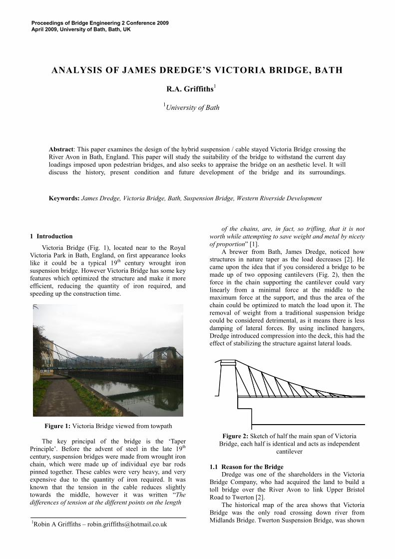
Victoria Bridge (Fig. 1), located near to the Royal
Victoria Park in Bath, England, on first appearance looks
like it could be a typical 19th
century wrought iron
suspension bridge. However Victoria Bridge has some key
features which optimized the structure and make it more
efficient, reducing the quantity of iron required, and
speeding up the construction time.
The key principal of the bridge is the ‘Taper
Principle’. Before the advent of steel in the late 19th
century, suspension bridges were made from wrought iron
chain, which were made up of individual eye bar rods
pinned together. These cables were very heavy, and very
expensive due to the quantity of iron required. It was
known that the tension in the cable reduces slightly
towards the middle, however it was written “The
differences of tension at the different points on the length
of the chains, are, in fact, so trifling, that it is not
worth while attempting to save weight and metal by nicety
of proportion” [1].
A brewer from Bath, James Dredge, noticed how
structures in nature taper as the load decreases [2]. He
came upon the idea that if you considered a bridge to be
made up of two opposing cantilevers (Fig. 2), then the
force in the chain supporting the cantilever could vary
linearly from a minimal force at the middle to the
maximum force at the support, and thus the area of the
chain could be optimized to match the load upon it. The
removal of weight from a traditional suspension bridge
could be considered detrimental, as it means there is less
damping of lateral forces. By using inclined hangers,
Dredge introduced compression into the deck, this had the
effect of stabilizing the structure against lateral loads.
1.1 Reason for the Bridge
Dredge was one of the shareholders in the Victoria
Bridge Company, who had acquired the land to build a
toll bridge over the River Avon to link Upper Bristol
Road to Twerton [2].
The historical map of the area shows that Victoria
Bridge was the only road crossing down river from
Midlands Bridge. Twerton Suspension Bridge, was shown
Proceedings of Bridge Engineering 2 Conference 2009
April 2009, University of Bath, Bath, UK
Figure 1: Victoria Bridge viewed from towpath
Figure 2: Sketch of half the main span of Victoria
Bridge, each half is identical and acts as independent
cantilever
1Robin A Griffiths – [email protected]

on the map, but was build after Victoria Bridge, by
Thomas Motley, who had entered a cable stayed rival to
Dredge’s Victoria Bridge design [2]. (Twerton Suspension
Bridge has since been replaced by Windsor Bridge).
On July 22 of 1836 Dredge patented his taper
principle bridge [3], around this time he started
construction of Victoria Bridge.
Victoria Bridge was opened by December of 1836
approximately 5 months after construction started. The
strength of the bridge had already been tested once when,
while partially constructed, a hurricane force storm hit
Bath and the bridge remained undamaged. [2]
Victoria Bridge would have become an important link
for traders wanting to get goods across the river without
using the ferries at lower Weston, including Dredge, who
no doubt used it to get his beer across the river from his
brewery on Upper Bristol Road.
1.2 History of Taper Principle
Dredge went on to build around 50 other bridges all
on the same patented taper principle. But he never
received much recognition for his improvement on the
traditional suspension principle [2].
When the Menai Bridge became damaged by winds
in 1839, Dredge even offered to undertake the repairs to
the bridge free of charge [4]. He was confident that the
scrap value of the iron he could remove from the structure
in converting it to his taper principle would pay for his
fee. His proposal was ignored even after one Lord
Western, who had visited Victoria Bridge and James
Dredge, wrote a letter to Lord Melbourne asking again for
Dredges proposal to be considered for the Menai Bridge
[4]. Lord Western was astonished that Dredges principle
had not been more widely accepted, stating in his letter
that Victoria Bridge had left “so strong an impression
upon my mind of the vast and immeasurable superiority
of the principle on which it is built, over anything that has
hitherto been attempted”[4]
Several reasons have been put forward for the demise
of the taper principle suspension bridge. The main one
being the invention of steel. Once suspension cables could
be manufactured out of strands of steel, the use of iron
chain stopped due to its cost and weight. Even Dredges
optimized iron cable could not compete with the long
spans possible with steel. No taper principle bridges were
built after 1869 [2].
1.3 Description of the Bridge
Some key dimensions of the bridge are given in Table
1 below. They are only approximate values, which will be
referred to in later calculations.
Table 1: Key Dimensions
Element Dimension (m)
Main span [2] 45.7
Deck width (Fig. 12) 5.8
Pier height from deck 6.4
Sag in chain [5] 6.6
1.3.1 Chains
Each of the two main span chains consists of 155
individual wrought iron links, arranged in 19 sections.
Each link is approximately 2.5m long and has a
rectangular cross section of 55mm*15mm. The end of
each link is circular with a shear pin running through it to
join it to the next link (Fig. 3). Two inclined hangers
come off the main chain at each joint to support the deck
The number of links used in each 2.5m stretch of chain
varies from the pier to the central point. At the top of the
pier the chain is made up from 12 links, which gradually
decreases to 5 links at the central point., this is the taper
principle.
The chains run over the top of the piers and down to
the ground. The length of chain behind the piers is made
up of 71 iron links, arranged in 8 sections. As in the main
span the number of links in each section of chain
decreases from 12 at the top of the pier to 7, where it is
anchored into the ground. At each pin 2 inclined hangers
come off the chain and are anchored into the ground, as a
result the end anchor block is relatively small (Fig. 4).
Figure 3: Bolted connection on the chain, note that the
number of links reduces from 8 to 7 at this node
Figure 4: Anchor blocks at the southern end of the chain

1.3.2 Piers
Each end of the bridge consists of two masonry
columns 2.2m wide (perpendicular to span) and 3.4m
deep. Each column tapers slightly towards the top, to
complement the principle of the bridge. Each pair of
columns is joined at the top by a masonry arch. The way
the chain runs over the top of the piers suggests that the
piers are not designed to take any considerable moment.
However there is undoubtedly some moment introduced
into the piers as the chain is not able to freely move over
the top of the pier, also the first hanger is built into the
side of the pier. (Fig. 5)
1.3.3 Hangers
At each node on the chain two inclined wrought iron
hangers come off the chain to either support the deck or,
beyond the piers, to dissipate the load into the ground.
The cross section of each hanger is the same as that of
each link in the chain 55mm*15mm. The angle of each
hanger varies, where the angle of the hanger to the
horizontal decreases towards the center so that “the
obliquity, as well as the stress upon the chains achieves its
minimum value.”[6] Each hanger connects to the edge
beam of the deck at approximately 1.1m centres (Fig. 6).
1.3.4 Deck
The deck consists of timber planks, which span in the
direction of the bridge. The roadway was originally stoned
[4], but at some later date, most possibly in the 1946
renovation it was replaced with asphalt. The timber planks
span in the direction of the bridges span, and are
supported by, and stapled down to, I beams at 0.5m
centres. These I beams span the entire width of the bridge
and connected inside the parallel flange channels (PFC’s),
to which the hangers attach (Fig. 6)
To provide stability to the deck the PFC’s are tied
together under the deck by a truss system at
approximately one every metre. Two fin plates run the
length of the bridge and the tensioned rods run from the
PFC under the fin plates and back up to the other PFC.
This has the effect of compressing the deck in the
transverse direction to prevent the I beams coming loose.
Table 2 below lists the elements of the deck as shown
in Figure 7.
Table 2: Elements of the bridge deck
�umber
(Fig. 7)
Description
1 Inclined hanger bar (55x15mm)
2 Box section supporting balustrade
3 Approx. 260x75x28 PFC edge beam
4 30mm dia. truss rod
5 Truss connector block
6 2 No. 20mm dia. Truss rods
7 Fin plate (130x15mm)
8 Hanger connection block
9 Balustrade post
10 Deck surfacing
11 Timber planking
12 175h 75w 12thk I beam
13 160x75 timber packing between I beams
Figure 5: View of the northern pier
Figure 6: Hanger connection detail
Figure 7: Cross section of the bridge deck
2 Aesthetic Appraisal
The famous bridge designer Fritz Leonhardt set out
10 areas of aesthetics. By analyzing how well Victoria
Bridge performs in some of the key areas a conclusion can
be drawn on its aesthetic.
2.1 Fulfillment of Function
With Victoria Bridge it is clear to see how the bridge
functions as a structure. The ‘chunky’ nature of
construction made out of iron and stone means that the
function of each element is obvious. With modern
materials it is possible to make structural elements ever
more slender, and thus the relationship between strength
and size can be distorted.
Most of the components and connections in the
bridge are on show, which helps show off how the bridge
is supported. This was crucial to Dredge as it was his first
bridge, and hence was a showcase, from which he could
adapt the design to future clients wishes.
The only detail on the bridge which looks out of place
is where the last hanger in the main span disappears into
the pier (Fig. 5). This is unlike all the other hangers which
clearly connect to the chain, and hence it looks out of
place.
2.2 Proportions
One element of the bridge which now looks out of
proportion is the balustrade. At 1.6m high it is quite high
for a pedestrian bridge. Also the fact that balustrade is the
same colour as the other ironwork on the bridge means
that in side profile it can clutter the view. It must be
remembered that when the bridge was built it was used as
a road for horse and cart. A higher balustrade would have
be preferable, as the driver of the cart would be higher up
off the deck.
When you approach the bridge on foot from the ends,
the density of bars in the balustrade obscures the view of
the bottom quarter of the chains. (Fig. 8) This disguises
the functional element of the bridge as discussed in 2.1.
Another element which looks quite out of proportion
are the anchor blocks (Fig. 4). In a traditional suspension
bridge they would be taking the load from half of a cable.
In Victoria Bridge, hangers into the ground reduce the
load in the cable as it approaches the anchor block. This
means a smaller anchor block is needed.
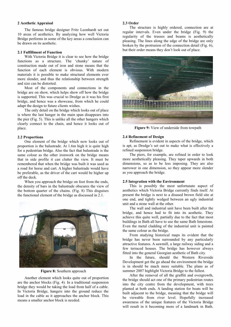
2.3 Order
The structure is highly ordered, connection are at
regular intervals. Even under the bridge (Fig. 9) the
regularity of the trusses and beams is aesthetically
pleasing. The lines along the edge of the bridge are only
broken by the protrusion of the connection detail (Fig. 6),
but their order means they don’t look out of place.
2.4 Refinement of Design
Refinement is evident in aspects of the bridge, which
is apt, as Dredge’s set out to make what is effectively a
refined suspension bridge.
The piers, for example, are refined in order to look
more aesthetically pleasing. They taper upwards in both
dimensions, so as to be less imposing. They are also
narrower in one dimension, so they appear more slender
as you approach the bridge.
2.5 Integration with the Environment
This is possibly the most unfortunate aspect of
aesthetics which Victoria Bridge currently finds itself. At
present the bridge is next to a disused brown field site at
one end, and tightly wedged between an ugly industrial
unit and a stone wall at the other.
The wall and industrial unit have been built after the
bridge, and hence had to fit into its aesthetic. They
achieve this quite well, partially due to the fact that most
buildings in Bath all have to use the same Bath limestone.
Even the metal cladding of the industrial unit is painted
the same colour as the bridge.
From studying historical maps its evident that the
bridge has never been surrounded by any particularly
attractive features. A sawmill, a large railway siding and a
few terraced houses. The bridge has however always
fitted into the general Georgian aesthetic of Bath city.
In the future, should the Western Riverside
Development get the go ahead the environment the bridge
is in should be much more suitable. The plans as of
summer 2007 highlight Victoria Bridge to the fullest.
After the removal of all the graffiti and overgrowth,
the bridge should act one of the primary pedestrian routes
into the city centre from the development, with trees
planted at both ends. A landing station for boats will be
built adjacent to the bridge, meaning that the bridge will
be viewable from river level. Hopefully increased
awareness of the unique features of the Victoria Bridge
will result in it becoming more of a landmark in Bath.
Figure 8: Southern approach
Figure 9: View of underside from towpath

The computer generated image below shows how the
bridge would fit into the surroundings. The image is taken
from the summer 2007 brochure. Unfortunately the
drawing of the bridge makes it appear unattractively
disproportionate, as the deck has been drawn much too
thick.
2.6 Texture and Colour
The texture and colour of the piers is attractive, and
fits into the textures found in Bath. All the ironwork on
the bridge has been painted green. This appears to be the
only colour that has been applied to the bridge, so may be
original, although it was no doubt repainted in the 1946
restoration. The colour fits well with the surroundings, the
river is a definite green colour as is visible in Figure 1.
The colour of the bridge does tend to cause it to blend it
into the background somewhat. Modern practice might
say to highlight the structural elements, to clearly display
the function by using colours such as red on the cables.
However this would not have been seen as attractive in
the 19th
century, and hence the colour fits with the design
of the bridge.
2.7 Aesthetics Conclusion
In its heyday Victoria Bridge was no doubt an
attractive bridge, but due to vandalism, as described in the
next section, it is not currently looking its best.
With Victoria Bridge the design certainly came before
giving any consideration to aesthetics. This bridge was
built to display Dredge’s new cost saving features in
suspension bridge construction and as a road link. It was
not until Dredge started building bridges in gardens of
stately homes and public parks that the aesthetic becomes
important. As a result the design changes, to look more
pleasing, but the overriding taper principle remains.
2.8 Vandalism
Victoria Bridge’s location, in a relatively quiet and
disused area of Bath, has led to a severe vandalism
problem. Newspaper clippings held at the Museum of
Bath at Work show that the bridge has had to undergo
several repairs due to vandalism attacks, including an
attack where a section of balustrade was ripped up,
resulting in the bridge being closed for a while.
Also, as is clearly evident in figures 1,5,6 and 8 there
is a lot of graffiti on the piers, and the edge of the deck. It
is worst above the towpath, as the bridge is within easy
reach. But even in less accessible areas graffiti is present,
as the chains are of a width that it is possible to walk up
and down them.
Not much can be done about this at present, other
than regular cleaning.. In the future, with the potential
Western Riverside Development the bridge will become a
lot busier and probably under CCTV monitoring. This
should result in the vandalism problem being almost
totally eliminated.
3 Construction
The total cost of the bridge was £1760, today this
would be equivalent to a £4.5m construction project. The
majority of the cost was spent on the masonry piers and
timber for the deck and falsework. The cost of the 21 tons
of iron work was only 25% of the total cost [4]. Not much
is known about the exact construction method employed
during the construction of Victoria Bridge. There has only
been one photograph discovered, of a Dredge bridge in
Northern Ireland during construction [7]. This is
discussed in Section 3.2.
3.1 Foundations and Ground Conditions
The ground conditions under the piers are likely to be
fluvial deposits from the river. These are generally soft
deposits, so it’s possible that some substantial foundation
system was required. If the loads were high and there was
a risk of slippage, then one possible foundation system
may have been timber piles. This would have involved
the driving of tree trunks into the ground and capping off
with timber planks or stone in order to provide a stable
platform for the piers. (Fig. 11a)
The modern day profile of the river is set by the sheet
pile edging, as visible in Figure 9. These would not have
been there in 1836 as they are most likely made of steel,
which hadn’t been invented. The historical map of the
area shows a more natural profile to the edge of the river.
If there was some kind of reinforcement to the edge
of the river, on the southern side in particular, then it
could be possible that shallow foundations were used
(Fig. 11b). This would have relied on the river wall
preventing slippage of the pier into the river. The wall
could have been either a stone wall, gabions or iron sheet
wall. In this case the foundations could be just crushed
stone and or timber planks. Whichever method Dredge
employed has worked, as no settlement cracks are visible
on the bridge.
3.2 Deck and Chain Construction
It is known that the construction of the chain began
onsite in November of 1836, just a month before the
opening of the bridge [4]. There have been suggestions
that Dredge had constructed his decks with a progressive
launching technique, common it modern day bridges.
However the photograph found in Northern Ireland and
Figure 10: Computer generated view of current
redevelopment plans
Figure 11: Two possible foundation systems under the
southern pier.
a b

the timeline of construction almost definitively points
towards the use of a timber falsework erected in the river.
The falsework would have been wider than the deck,
to allow access to down the sides. The ironwork frame of
the deck would have been constructed off the falsework.
The tensioning of the truss system would have stabilized
the I beams, resistance from lateral movement would be
provided by the timber. The timber is restrained by the
box sections supporting the balustrade.
The last stage of construction would have been to
construct and hang the chain, then attach the hangers to
the deck and remove the falsework. As mentioned
previously, this last stage took only 1 month to complete.
3.3 Durability and Repairs
The durability of Victoria Bridge is evident in that it
has survived for so long. Even later Dredge bridges have
not survived as well, with only a handful still standing. All
of the operational bridges have undergone some
restoration at some stage, varying from re-timbering of the
deck to total dismantling and reconstruction [7]. As this
was Dredges first bridge, he wanted to make sure it
definitely survived well, as he used it as his flagship
bridge which was mentioned in advertisements that he
sent out (Fig. 12).
Repairs to Victoria Bridge include the re-surfacing of
the deck, repainting of the ironwork and patch repairs to
damages ironwork caused either by corrosion, stress or
vandalism.
The ironwork in the underside of the deck has
suffered some considerable corrosion, and the surface of
the iron is rough and in some places flakey. The repainting
of the ironwork has helped in preventing further
corrosion, as evident in Figure 13, only the underside of
the box section supporting the balustrade (Fig. 7, Item 2)
is currently suffering severe corrosion from water ingress
down the side of the bridge surfacing. This is a
considerable design flaw in the bridge, in that it does not
feature a drainage channel anywhere on the deck. The
impermeability of the surfacing means all water runs to
the edge, but the upstanding box section at the edge
means water must flow down between the timber and the
box section. This allows a considerable flow of water to
trickle down the ends of the I beams, as visible in Figure
13.
The condition of the chain is generally good, some
paint has started to peel off, which has lead to the start of
light corrosion to some links. Mould growth and algae
growth on the underside of the chain is also evident on
most of the chain. The structural condition of the links
has also been checked at some stage, as there is a repair to
one of the links, as shown in Figure 14. The damaged link
has had two equally sized iron bars welded to either side
of the link. The fact that only one link has needed repair,
out of hundreds on the bridge is testament to its ongoing
durability.
4 Structural Analysis
This section will evaluate the structural capacity of
Victoria Bridge, and comment on its suitability to meet
modern day British Standards.
In some cases the bridge will have assumed to be
made of steel, as the British Standards do not refer to
wrought iron. The material properties of wrought iron are
slightly different to steel, values that have been assumed
are given in Table 3.
Table 3: Properties of Wrought (Pure) Iron
Property Value
Coefficient of thermal expansion [8] 12*10-6/oC
Young’s modulus [8] 190kN/mm2
Ultimate tensile strength [8] (see note 1) 340N/mm2
Yield stress [8] 210N/mm2
Figure 12: Dredge advertisement poster, discovered by J.
Popplewell of Paglesham, Essex, in a 19th
century writing
box, a family heirloom.
Figure 13: Corrosion to the underside of the deck above
towpath.
Figure 14: Algae, rust and repair to damaged link

NOTE 1: Dredge assumed an ultimate tensile strength of
403N/mm2 and individually load tested the chain rods to
140N/mm2, implying a factor of safety of about 3. [2]
4.1 Loadings
The loading will be calculated in accordance with BS
5400:2-2006. The design loads used by Dredge are also
known, they will be compared to modern specifications.
4.1.1 Dead Load
A dead load takedown of all the structural elements of
the bridge was carried out using the dimensions given in
Table 1&2. The load takedown was then calibrated by
ensuring that the total amount of iron employed in the
structure was approximately equal to the 21 Tons quoted
by Dredge. The average dead load in the main span was
averaged over the area of the bridge to give a final un-
factored value of 0.8kN/m2.
4.1.2 Superimposed Dead Load
The architectural ironwork (Balustrade), timber deck
and asphalt surfacing make up the superimposed dead
load. By assuming a 50mm timber deck, 25mm asphalt
surface and a balustrade of 0.5kN/m run. The
superimposed dead load averaged over the area of the
bridge was found to be 1kN/m2, un-factored.
4.1.3 Live/Primary Live Loads
When it was designed Victoria Bridge was to be a
road bridge. Loadings of the day, suggest that a value
between 6kN/m2 and 7kN/m
2 would have been used for
vehicular traffic and potential military use [2].
Now that the bridge is only a pedestrian bridge a
lower value is specified in BS 5400 Clause 6.5.1. The
loading is given as k x 5kN/m2, where k is given Eq. 1
below.
� = ���. �� �� �� �����ℎ � ������ ∗ 10� + 270
The nominal HA load for a bridge of 45.7m length is
26kN/m2, given from BS 5400 Clause 6.2.1. Therefore k
is equal to 0.824. Clause 6.5.1.1 allows for further
reduction in UDL for pedestrian bridges over 2m wide.
Resulting in a final UDL of 3.7kN/m2. This is just over
50% of the original design load.
4.1.4 Secondary Live and Accidental Loads
Secondary live loads caused by the dynamic
movement of vehicles, or accidental vehicular loading
need not be considered, as the bridge is adequately
protected by bollards. Proposals for nearby development
include the removal of the road leading to the bridge and
the use of the bridge for construction traffic would likely
not be permitted. From the river, the piers are protected by
the sheet walling. The height of the bridge above water
level is quite low compared to other bridges along the
river, but there would be other bridges on the river that
would prevent a tall boat reaching and hitting the deck of
Victoria Bridge.
Should floodwater ever reach the deck of the bridge it
would almost certainly cause the destruction of the bridge,
as happened with several other of Dredges bridges. In
later examples, Dredge adapted his designs with elaborate
cross bracing designs to protect from flood water. The
likelihood of the river flooding to such a height is
hopefully minute, as the river level is controlled by the
weir further downriver and it would probably also result
in considerable flooding of the city.
Figure 15 below shows what happened when a
overweight vehicle is driven onto a Dredge bridge. This
unfortunate accidental loading happened to the Ballievy
Bridge in Northern Ireland. It was functioning as a public
road bridge up to the 12th
of September 1988 when a 27t
lorry got lost and attempted to cross the bridge, despite
weight limit signs.
The damage was so extensive that the bridge could
not be repaired. The remains of the bridge are held in
storage. [7]
4.1.5 Wind Load
The maximum wind gust speed can be calculated
from BS 5400 Clause 5.3. The modification factors that
have to be considered for the bridges location include,
altitude factor, distance from the sea, the urbanization
factor and that Bath is in a valley, which could cause wind
tunneling. Taking all these into account gives a maximum
wind gust speed (Vd), of 38.8 m/s. From this the dynamic
pressure head (q) can be calculated to be 0.923 kN/m2.
The shape of the bridge means it fits well in the
categories given in BS 5400, which means that wind
tunnel testing would likely not be required. There are no
aerofoil effects, re-entrant angles or super elevation
effects to consider on the bridge.
The horizontal wind load (Pt) acting on the bridge is
calculated by multiplying q by the projected area of the
bridge, and a drag coefficient. The projected area of the
bridge is 29m, this takes into account the thickness of the
deck, and also the area of the hangers and chain, as they
are flat bars. When there is live load on the bridge the
projected area increases to 85.3m. The drag coefficient
for both cases is 2, the minimum that can be used for
(1)
Figure 15: Death of Ballievy Bridge (from Ref. 7)

pedestrian bridges. This gives a horizontal force of 54kN
or 157kN (with live), which is assumed to act at the centre
of the bridge.
The longitudinal wind force (PL) is a nominal force
acting on the bridge and puts the deck into compression
and tension, as there are no bearings at the ends of the
deck. The force on the live load, and the force on the
superstructure must be considered. They were calculated
to be 34kN and 14kN respectively. This gives a total force
of 48kN, acting at the centroid of the bridge.
The wind can also act vertically on the bridge,
causing uplift, or down force. As there are no aerofoil
effects it can be calculated easily by multiplying q by the
plan area and a lift coefficient. Assuming a lift coefficient
of 0.4, gives a vertical force (Pv) of ±96kN.
These different wind load cases should then be
considered in one of the 4 combinations given in Table 4.
Combination 2 is usually found to be dominant. Table 4: Wind load combinations CombinationCombinationCombinationCombination PPPPt t t t (kN)(kN)(kN)(kN) ±P±P±P±Pv v v v (kN)(kN)(kN)(kN) PPPPL L L L (kN)(kN)(kN)(kN) 1 Pt 157 0 0 2 Pt with ±Pv 157 96 0 3 PL 0 0 48
4 0.5Pt with PL and ±0.5Pv 78.5 48 48
4.1.6 Temperature Load
Variation in the effective temperature will cause the
iron elements to expand and contract. Two locations
where this may cause a problem are in the PFC’s running
the length of the bridge and in the transverse I beams.
Differential temperatures in the bridge deck are not
likely to cause much of a problem, as the timber deck and
iron structure are not structurally jointed together. Hence
there will be practically no stress at the interface.
The ends of the PFC are butted up close to the piers,
although not attached, there is little room to expand, and
hence stress could build up in the PFC. The maximum
stress in the member can be calculated using Equation 2.
7 = ∆9:; Where:
∆T = Change in temperature from datum (oC)
α = Coefficient of thermal expansion (*10-6
/oC)
E = Young’s modulus (N/mm2)
Assuming a potential temperature change of 25oC,
this gives a stress of 57N/mm2. Which, assuming the PFC
size from Table 2, gives an sectional area of 3510mm2,
hence a force of 200kN, assuming no expansion room at
the ends. This force could only be a compressive force
due to temperature increases in the PFC’s as they are free
to contract. This force could potentially cause the PFC’s
to buckle. The compressive strength of the PFC can be
calculated from BS 5950-1:2000 Clause 4.7, as it is not
steel it is required to reduce the capacity slightly for the
lower yield stress of wrought iron. The PFC is restrained
at approximately 0.5m centers by I beams or tension rods,
which will restrain buckling. The maximum permissible
compressive force in the PFC is calculated to be 737kN.
This is well above the potential maximum force in the
member due to temperature of 200kN. It is unlikely that a
full 200kN would be put into the PFC, as long as there is
some room at the ends.
< = ∆9:�
Where:
L = Length of member (mm)
Equation 3 gives the lengthening of the beam that
would be observed if it was free to expand. Assuming the
same values as in Equation 2 and the bridge length of
45700mm, gives an expansion of 13.7mm (6.85mm at
each end). As long as there is at least this amount of space
at the ends no stress would be put into the PFC’s.
If the I beams expand then they will apply a lateral
force to the PFC’s, this would increases the stresses in the
truss rods that ties the 2 PFC’s together. The level of
stress in the truss rods is hard to ascertain, as the level of
pre-stress is unknown. Also, the rods would be expanding
due to temperature as well, which means the stresses
could be lower, if the whole bridge expanded laterally.
4.2 Loading Combinations
BS 5400 states 5 loading combinations that must be
checked at service limit state (SLS) and ultimate limit
state (ULS). The load case for secondary live loads need
not be considered on Victoria Bridge as it is not subjected
to vehicular traffic. Also the load case which includes
friction at supports need not be considered here. The load
combinations must be multiplied by the relevant design
load factors (γfl) given in Table 5, and additional factor γf3
(1 at SLS and 1.1 at ULS.)
Table 5: Dead load factors, γfl
Load Combination
1 2 3
Dead ULS 1.05 1.05 1.05
SLS 1.00 1.00 1.00
Super-
imposed Dead
ULS 1.75 1.75 1.75
SLS 1.20 1.20 1.20
Primary Live ULS 1.50 1.25 1.25
SLS 1.00 1.00 1.00
Wind ULS 0.00 1.10 0.00
SLS 0.00 1.00 0.00
Temperature ULS 0.00 0.00 1.30
SLS 0.00 0.00 1.00
4.3 Element capacities
To perform a basic structural analysis the capacity of
a few key elements of the bridge can be checked against
the load combination in Table 5 that gives the worst effect
on that element. Some element that may prove critical are
the deck, hanger and chain. For a more complete
structural analysis a computer model of the bridge could
be produced using software such as STAAD Pro. This
would allow the more complex load combinations to be
considered more accurately, as well as being able to
model dynamic loadings.
4.3.1 Chain capacity
As the connections in the chain are all pinned, the
chain will not take lateral loads. The worst case load
combination is therefore when there is the highest vertical
force. The occurs in load combination 2, including
vertical wind loading.
(2)
(3)

The forces in the hangers, and hence the forces in the
chain can be determined by resolution at the joints.
With reference to Figure 16, it can be assumed that
the loading on the deck is transferred to the edges, and can
be assumed to act as a line load (W). For the worst case
loading condition described above, W is 22.2kN/m at
ULS. The force transferred into the hangers (Fh) varies
depending on the obliquity of the hanger (θ), the resulting
compression force in the deck (Fd) is also dependant on
the obliquity of the hanger.
The forces at the node of the chain consist of the two
hanger loads and the load of the preceding section of
chain, which are all taken by the succeeding section of
chain. The angle of the chain (θc) is assumed to be a
constant 17o, although in reality the angle of the chain
varies due to sag. Using a constant value of θc gives a
constant step up of the force in each section of chain (Fc).
By tabulating the calculation, the forces in each
section of the chain was found to vary from 234kN at the
central section, to 1570kN at the top of the pier, with an
increase of 167kN at each node in between. At the centre
there are 5 links in the chain, each link takes 1/5th
of the
load, which is 47kN. At the pier there are 12 links in the
chain, each link takes 1/12th
of the load, which is 131kN,
these links have the highest load. Given that the link cross
section is 55mm by 15mm, it can be deduced that the max
stress in the links is 131,000/(55*15)=159N/mm2. Taking
the modern value for ultimate yield stress of 340N/mm2
gives a factor of safety of 2.14 at ULS. Given that the
ironwork is old, has deteriorated slightly and will not have
been manufactured to modern standards, a factor of safety
of nearer 4 may be preferable.
4.3.2 Hanger capacity
As the hangers become more inclined towards the
middle the force will increase, as they all support the same
tributary area of the bridge deck. The hanger closest to the
centre is inclined at 6o from the horizontal. The worst case
loading is the same as for the chain. Therefore a simple
calculation for the tension in the hanger could be
T=(22.2*1.1)/sin 6=234kN. This relates to a stress of
234,000/(55*15)= 284N/mm2, which gives a factor of
safety of only 1.2. The stress may not be this high, as
some of this load is likely to be taken by the first chain
section, the first chain section consists of 5 links, whereas
the hanger is just 1.
With the tension in the hangers increasing with the
inclination it is perhaps an oversight that Dredge did not
apply the taper principle to the hangers also. The tensions
in the hangers appear to vary from 234kN to only 23kN.
This effect was explained by W. Turnbull in his paper
‘Dredge’s suspension bridge explained upon the principle
of a lever’ [6]. He explained “Another condition in the
system of calculation might be, to have the effects of all
the suspending [hanger] forces equal; we do not mean the
absolute magnitude of the forces, but the effects as
referred to their particular direction, when compared with
the state of equilibrium; this would manifestly give a
series of equal differences for the tensions on the chain”
4.3.3 Deck capacity
Dredge’s design was criticized for inducing
compression into the deck and not suitably allowing for
this force. Compression is induced by the inclination of
the hangers, which generates the reaction forces (Fd), as
shown in Figure 16. If you are considering the bridge to
be made of two entirely independent cantilevers, as
suggested by Dredge, these reactions add up resulting in a
large compression force at the pier, most of which is
carried by the PFC, as not much will be transferred by
shear into the rest of the deck. However the two
cantilevers are connected across the middle, this has the
effect of making the two compression forces act against
each other, creating a tension force in the PFC. The
tension capacity of the PFC’s are a lot higher than the
compression capacity. The maximum compression force
will be produced when there is a maximum load (dead,
super-dead, live and wind all at ULS) on one half of the
bridge, and a minimum force on the other half (dead, and
super-dead at SLS). The maximum compression load in
the PFC’s due to out of balance forces on the bridge is
calculated to be 560kN, in each PFC, for combination 1
loads (Table 5). This is below the ultimate compressive
capacity calculated in Section 4.1.6 of 737kN. However
the compression will be higher due to wind or
temperature forces in combination 2 and 3 loading.
In combination 2 lateral wind loads will also induce
compression and tension forces in the PFC’s. As there is
no diagonal bracing under the deck, lateral loads will
taken purely by the deck as if it were a beam on its side,
putting one PFC in tension and the other in compression.
The magnitude of these forces works out at approximately
±290kN tension or compression. This is added to the
compression due to out of balance loading, which due to
the reduced factors of safety in combination 2 and 3
works out as 480kN, so that the total compression in
combination 2 becomes 480kN+(290*1.1)kN = 799kN. In
combination 3 the temperature effect from Section 4.1.6
is added instead of wind to give 480kN+(200*1.3)kN =
740kN. Both of these are near too, but over, the ultimate
compression capacity of the PFC of 737kN.
In the British Standard the wind and temperature
loads are calculated using measured data of maximum
wind speeds and temperatures based on a 120 year return
period. As of now, Victoria Bridge is 173 years old,
meaning statistically it should have seen at some time
wind speeds and temperatures worse than used in the
British Standard. In conclusion, could it therefore be said
Figure 16: Forces in the bridge deck, hangers and chain

that the bridge had been ‘load tested’ against these
environmental loads, as it has stood the test of time, and
hence is adequate?
4.4 �atural Frequency Effects
BS 5400:2-2006 Annex B stipulates that the
fundamental natural frequency of pedestrian brides must
be greater than 5Hz vertically.
= = >?2@�? A;B�C
In order to evaluate the vertical natural frequency, the
serviceability loading is assumed to include the
superimposed dead load, but not the pedestrian live load.
This relates to a load per metre (M) of 11.2kN/m. The I
value for the bridge’s width at midspan is roughly equal to
6x10¹⁰
mm4 = 0.06m
4. This is put into Equation 4 gives a
natural frequency of 7.8Hz.
Vibration should therefore not be a problem for the
bridge deck, although the frequency is relatively low. This
has been noticed on the bridge, as the deck is quite
flexible, one person jumping on the deck can cause a
slight resonation. Also, when there is a group of people
walking across the bridge, some resonation begins in the
chains. It could therefore be suggested that the natural
frequency should be checked in other parts of the bridge,
this could be best done in computer modeling.
4.5 Serviceability
Serviceability checks for cracking or creep are not
required in this case as the bridge is not made of concrete.
For an iron structure such as this, suitable serviceability
checks would be deflection checks. Deflection of the I
beams would want to be minimized to prevent the deck
from bowing, which would be noticed as water would
pond in the middle of the deck. Assuming a uniform load
at serviceability of 6kN/m, the deflection can be found
simply, with Equation 5, which is based on the assumption
of a simply supported uniformly loaded beam.
< = 5D�E384;B
The I value for the beams is 15,420,601mm4. The
effective length of the beams is reduced, as they are
partially supported by the truss system at third points. The
effective length could be assumed to be 0.85 of the actual
length (5.8*0.85 = 4.93m). This in Equation 5 gives a
central deflection of 16mm. Modern day BS:5950 for
steel, would suggest a limiting deflection to be span/250,
which would be 23mm, hence the bridge passes this
serviceability check.
5 Conclusions
Dredge principle received much scrutiny by
mathematicians of the day, which resulted in heated
debate, and even ridicule [2]. From the structural analysis
carried out in this paper, it seems apparent that although
the forces in the chain have been reduced, to allow
tapering the cross section of the chain, this has come at
the cost of inducing potentially troublesome forces in the
hangers and deck. These forces would not be present in
traditional suspension bridges, although in Dredge’s
bridge they do help reduce the effect of the 4 pin
mechanism of a traditional suspension bridge, which
normally leads to lateral stability issues.
One area where the design could be improved is in
the angle of the hangers. The original document
explaining the principle of the bridge [6], states that there
is no conditional equation to set the position and angle of
the hangers, and that “successful application of the
principle to practice, must in a great measure depend
upon the sagacity and skill of the engineer by whom the
fabric is raised”. If the angle of the hangers is required to
vary then a further refinement would be to taper the size
of the hangers. Alternatively, the angle of the hangers
could be fixed, using the analysis method in Section
4.3.1, using a fixed angle for the hangers does not affect
the force in the chain.
Acknowledgements
The author wishes to thank S. Burroughs, director of
Museum of Bath at Work, for access to their archive. N.
Watson, for the loan of her camera. Also, J. Popplewell,
for finding Dredges advertisement.
References
[1] Drewry C.S., 1832. A Memoir on Suspension
Bridges, Longman, London, pp. 166-168
[2] McQuillan D., Feb 1994. From brewer to bridge
builder: reflection on the life and work of James
Dredge, Proceedings of the Institute of Civil
Engineer, Civil Engineering, Vol. 102, ICE, London,
pp. 34-42
[3] The Repertory of Patent Inventions, and other
Discoberies & Improvements in Arts, Manufacture
and Agriculture, Vol. VIII, 1838, Hodson, London,
pp. 316
[4] Letter from Lord Western to Lord Melbourne,
descriptive of a Suspension Bridge on a new
principle, built across the Avon at Bath, by Mr
Dredge, Mechanics’ Magazine, Vol. XXXII, 1840,
Robertson, London, pp. 706-708.
[5] Hague D., 1979. Victoria Bridge, Bath, Bristol
Industrial Archaeological Society Journal, Vol 12,
pp. 27-28.
[6] Turnbull W., 1841. Dredge’s suspension bridge
explained upon the principle of a lever, Weale,
London
[7] McQuillan D., April 1992. Dredge suspension
bridges in Northern Ireland: history and heritage, The
Structural Engineer, Vol. 70, No. 7, IStructE,
London, pp. 119-126
[8] Cobb F., 2004. Structural Engineer’s Pocket Book,
Elsevier, London, pp. 61.
(4)
(5)