Aalto University School of Engineering
33
MEC-E2004 Ship Dynamics (L) Lecture 9 Additional Seakeeping Topics Aalto University School of Engineering
Transcript of Aalto University School of Engineering

MEC-E2004 Ship Dynamics (L)
Lecture 9
Additional Seakeeping Topics
Aalto University
School of Engineering
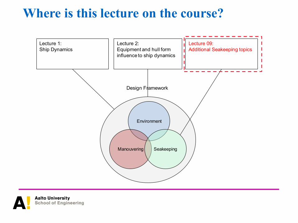
Where is this lecture on the course?
Environment
Manouvering Seakeeping
Lecture 09:
Additional Seakeeping topics
Lecture 1:
Ship Dynamics
Design Framework
Lecture 2:
Equipment and hull form
influence to ship dynamics

• Aim : Understand key issues related to local loads (e.g. slamming, green water on deck, sloshing
etc.) and how different criteria (e.g. motion sickness, voluntary speed loss) are set and assessed for
asset safety, people safety and operational performance. A brief overview of seakeeping model tests
is also provided. Examples of criteria looked at are motion sickness and voluntary speed loss.
• Literature:
1. Lloyd, A.R.J.M., “Seakeeping – Ship Behavior in Rough Weather”, Chapters 21-23
2. Razola, M., “New Perspectives on Analysis and Design of High- Speed Craft with Respect to
Slamming”, Doctoral Thesis, KTH, 2016
3. RED Bishop and WG Price, Hydroelasticity of Ships, Cambridge University press ISBN
9780080439211
4. Yong Bai, Chapter 2 - Wave Loads for Ship Design and Classification, In Marine Structural Design,
Elsevier Science, Oxford, 2003, Pages 19-37, ISBN 9780080439211
5. Lewis E.V., Principles of Naval Architecture Vol.3 ‘Motions in waves and controllability’
Contents

Motivation• Excessive ship motions, accelerations and loads may lead to
significant asset risks, can make onboard operations unsafe
or difficult and may be harmful for people’s health.
• Good example is the habitability of passenger ships. In the
cruise sector excessive motions can be harmful for people
and bad for business.
• When designing a ship the mission has large impact on the
criteria we can use for acceptable responses. For example,
war ship operability standards can be fairly different to
passenger ship or luxury yacht standards. In any case we
have to identify the responses early on in the design stage
and limit operations.

Assignment 5
• Grades 1-3:
✓ Select book-chapters related with (1) seakeeping design criteria (2)
added resistance (3) maneuvering and reflect to your ship
✓ Assess seakeeping criteria with some software and assess the
performance of the initial design with respect to those
✓ Discuss the simplifications made in added resistance/maneuvering modelling and analysis of your ship
✓ Select the maneuvering tests to be simulated and justify the selections
• Grades 4-5:
✓ Based on scientific literature, discuss the accuracy of the obtained
results
✓ Compute the part of added resistance in selected wave conditions in relation to still water resistance & discuss results
✓ Discuss what issues you can still improve for you ship in the follow-up
courses
• Report and discuss the work.

Local Loads• Local wave / fluid induced loads act usually over small area of the vessel. These loads are usually
absorbed by the local structure.
• Panting is an in/out motion of the plating in way of the bow of the ship caused by unequal water
pressure as the bow passes through successive waves. It is greater on fine bow ships. Fore peak
tanks are designed to resist it.

Local Loads – Pounding leading to bow slamming
• As a ship moves through the water fluid actions (i.e. hydrodynamic forces) push in and out in a cyclic
fashion in way of the waterline / bow area of the vessel. As the ship moves trough the water
especially in large head seas the bow tends to lift clear of the water. As it drops back to the sea the
vessel slams at the forefoot. The phenomenon in known as pounding or bow slamming.
• The phenomenon is linked up with heavy pitching assisted by heaving as the whole ship is lifted in a
seaway. Based on in service experience it is believed that that greatest effect is experienced in the
lightship condition. To compensate for this the bottom over 30% fwd of the ship strengthened for
ships exceeding 65m in length when min draft is less than 0.045L(OA) in any operating condition.
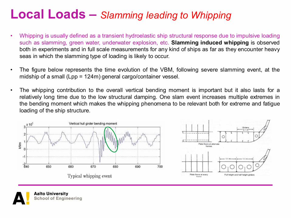
Local Loads – Slamming leading to Whipping
• Whipping is usually defined as a transient hydroelastic ship structural response due to impulsive loading
such as slamming, green water, underwater explosion, etc. Slamming induced whipping is observed
both in experiments and in full scale measurements for any kind of ships as far as they encounter heavy
seas in which the slamming type of loading is likely to occur.
• The figure below represents the time evolution of the VBM, following severe slamming event, at the
midship of a small (Lpp = 124m) general cargo/container vessel.
• The whipping contribution to the overall vertical bending moment is important but it also lasts for a
relatively long time due to the low structural damping. One slam event increases multiple extremes in
the bending moment which makes the whipping phenomena to be relevant both for extreme and fatigue
loading of the ship structure.

Whipping – Wave VBM + Impact response• Whipping is caused by impact type loading due to harsh
weather conditions
• The key issue is the relative motion and speed
between the ship and waves
• The impact load causes transient vibrations on the ship,
which is called whipping (compare to springing)
-2
-1,5
-1
-0,5
0
0,5
1
1,5
0 5 10 15 20 25 30
Time evolution of the stresses following
severe slamming event

Can we sperate springing from whipping?• If wave encounter frequency = frequency of hull girder
we experience springing. The phenomenon is more
evident in ships with low natural frequency (i.e. low
stiffness /mass ratio).
• Springing may also contribute to the extreme response
for some ships, but springing vibrations are generally
more important for fatigue, up to 50%.
• When a transient load causes hull girder vibrations the
phenomenon is whipping.
• In some wave conditions a ship may experience
slamming loads for almost every wave encounter and
then these two phenomena occur at the same time.
If the damping is low, this gives rise to continuous hull
girder vibrations. This illustrates that there is not
always a clear distinction between whipping and
springing.
-2
-1,5
-1
-0,5
0
0,5
1
1,5
0 12,5 25
2-nodes
Slamming causes impact load ;
due to this load vibrations occur

Whipping FFSI – a basic TD model
• Whipping is a hydroelastic phenomenon. It is idealised by 2D beam dynamics coupled with 2D (strip
theory) or 3D potential flow (FD or TD) hydrodynamics. Full 3D models studying the combined
influence of symmetric and antisymmetric distortions on ship dynamics do not exist. All hydroelastic
theories are symmetric.
• The numerical model we use is based on coupling between 3D diffraction / radiation Hydrodynamic
principles and Timoshenko beam dynamics. The modal approach presented in SD8 is followed and
the equation used in the time domain is :
Vector of modal amplitudes
Modal mass matrix
Infinite frequency added mass matrix
Damping matrix
Structural stiffness matrix
Hydrostatic restoring matrix
Matrix of hydro memory functions
Non impulsive wave loading
Vector of impulsive loads
Matrix size 6 motions + N symmetric distortions
1. RED Bishop and WG Price, Hydroelasticity of Ships,
Cambridge University press ISBN 9780080439211

Slamming FSI (rigid body)
• Slamming is the result of large relative motion between ship
and waves. It relates with displacement and speed. It may
cause local damages on bottom structures and vibrations
called whipping
• The relative motion is defined as difference between
➢ Ship vertical motion w(x,t)
➢ Wave height (x,t)
CGx
z
y
(x, t)
w(x, t)
F
T
( ) ( ) ( )txtxwtxz ,,, −=
• The notation
➢ z(x,t)>T, the bottom is in the air → possible slamming occurs
➢ z(x,t)<-F, the deck gets submerged → shipping of green water occurs
• For slamming to conditions need to be fulfilled
➢ The bow has to be in the air, z(x,t)>T
➢ The vertical speed of bow or stern has to exceed certain tresshold value

Slamming Assessment...(cont.)• Highly coupled, nonlinear problem
• Fast process
• The structure and flow solutions can be strongly coupled
(pressure distribution)
• The number of peaks must be assessed during ship
operations
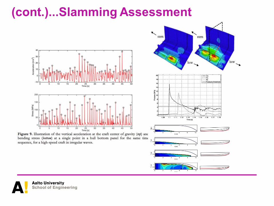
(cont.)...Slamming Assessment
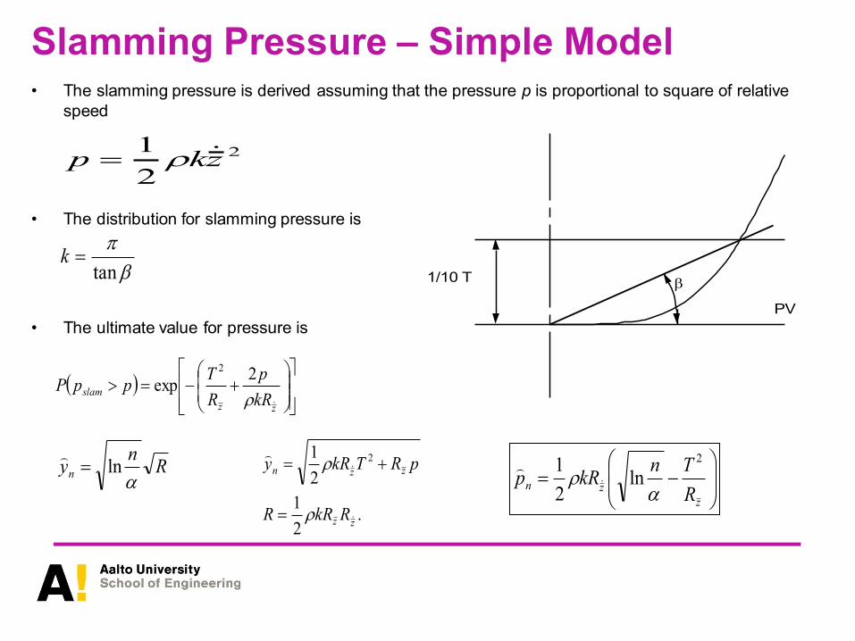
Slamming Pressure – Simple Model• The slamming pressure is derived assuming that the pressure p is proportional to square of relative
speed
• The distribution for slamming pressure is
• The ultimate value for pressure is
2
2
1zkp =
tan=k
1/10 T
PV
( )
+−=
zz
slamkR
p
R
TppP
2exp
2
−=
z
znR
TnkRp
2
ln2
1
Rn
yn
ln=
.2
1
2
1 2
zz
zzn
RkRR
pRTkRy
=
+=
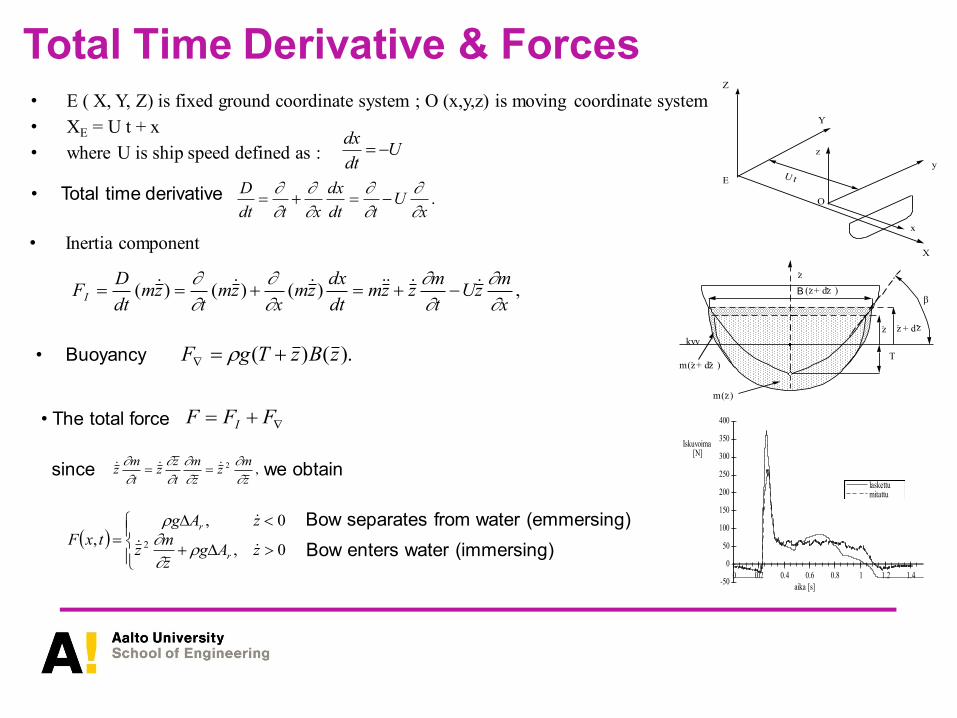
Total Time Derivative & Forces• E ( X, Y, Z) is fixed ground coordinate system ; O (x,y,z) is moving coordinate system
• XE = U t + x
• where U is ship speed defined as :
E
Z
Y
X
x
y
z
O
U t
• Total time derivative
dx
dt= −U
.x
Utdt
dx
xtdt
D
−=+=
• Inertia component
• Buoyancykvv
T
m( )
z
z
m( + d )z z
z + d z z
( + d )z zB
-50
0
50
100
150
200
250
300
350
400
0 0.2 0.4 0.6 0.8 1 1.2 1.4
laskettumitattu
Iskuvoima [N]
aika [s]
• The total force
,)()()(x
mzU
t
mzzm
dt
dxzm
xzm
tzm
dt
DFI
−+=+==
).()( zBzTgF +=
+= FFF I
since we obtain ,2
z
mz
z
m
t
zz
t
mz
==
( )
+
=0,
0,
, 2 zAgz
mz
zAg
txFr
r
Bow enters water (immersing)
Bow separates from water (emmersing)
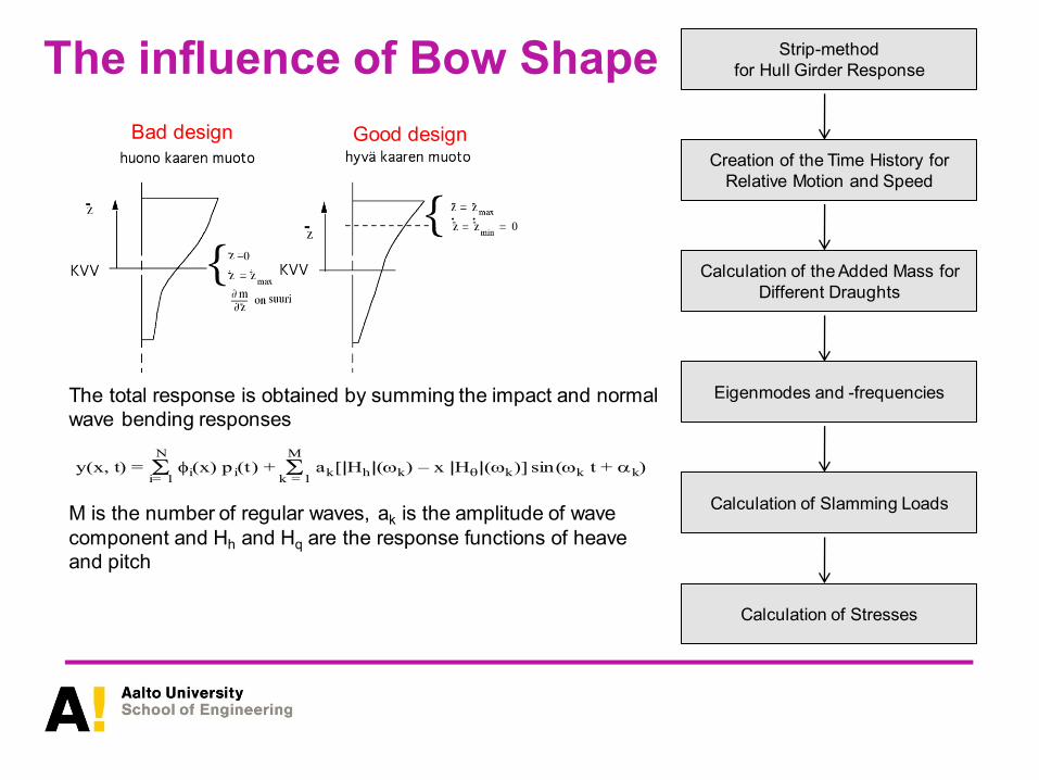
The influence of Bow Shape
Bad design Good design
The total response is obtained by summing the impact and normal
wave bending responses
M is the number of regular waves, ak is the amplitude of wave
component and Hh and Hq are the response functions of heave
and pitch
y(x, t) = i(x) p i(t)
i= 1
N
+ akk = 1
M
[ Hh (k) – x H (k)] sin(k t + k)
Strip-method
for Hull Girder Response
Creation of the Time History for
Relative Motion and Speed
Calculation of the Added Mass for
Different Draughts
Eigenmodes and -frequencies
Calculation of Slamming Loads
Calculation of Stresses

Example – The Rauma Class
• Usually beam model is sufficient for whipping calculations sincewe need only the hull girder bending modes (s1-level)
• In present case 3D-FEM was used since
➢ Significant influence of superstructure
➢ Discontinuities
➢ Bulkheads
• The mass of water was included (added mass) by FEM analysis(infinite and finite size)
• Only the most significant modes are presented
➢ The modes with large displacements at bow are importantsince then the force works (W=F*u)
➢ Two first modes are beam modes while the 5th modeincludes also the superstructure deformations
LOA= 48.0 m
B = 8.00 m
Displacement 215 tons
T = about 2 m
v = 30+ knots.

Whipping-Analysis
• Changes in bow halved the load
• Normal stress presented in the figure below
shows significant increase in the sagging
moment

Motion Sickness - Introduction • Balance organs are located in the inner ear and can
detect both magnitude and direction of gravity and
motion effects.
• Excessive stimulation of this organ may lead to motion
sickness
• The organ is linked to signals coming from the eye
➢ Motion sickness can be caused without
movement
➢ Blocking signal from eyes can cause motion
sickness
• Seeing the horizon helps to reduce motion sickness
as the “conflicting signals” will be in agreement (rigid
body motion)
• Anxiety, hunger, fatigue and smells can promote
motion sickness
• Motion sickness decreases in couple of days typically
(adaptivity)

Measures of Ship Performance - MSI
• Motion Sickness Incidence (MSI). Experience shows that the principal cause of sea sickness appears
to be a result of vertical accelerations. Experiments carried out in the 70s with 300 male volunteers in the
USA positioned in a cabin subject to sinusoidal vertical motion with amplitude up to 3.5 m. MSI has been
defined as the percentage of participants who vomited in the first 2 hrs of the experiment. The MSI was
expressed in the form
• Hypothesis is that the vertical acceleration causes the motion sickness
➢ Other motion components are typically very small in ships to cause this
➢ Location on ship affects this as the rotations will add to the vertical accelerations through rigid body
motions – worst place bow and stern
• The error function is expressed as
• The method assumes that ship accelerations are expressed as gaussian distributions. So the vertical
acceleration is where is the RMS value of vertical acceleration

Measures of Ship Performance - MSI

Measures of Ship Performance - SMSubjective Magnitude (SM). In mid 70s a number of pilots were subjected to an experiment of
sinusoidal vertical motions using a chair capable of amplitudes up to 1.5m. The objective of the
experiment was to quantify the influence of motions on their ability to work effectively. A reference
motion at 1 Hz with acceleration of 0.6g was assigned an SM (10).A motion judged to be twice as
severe was assigned SM (20), half as severe SM (5) etc. The data obtained were expressed in the
form
The acceleration amplitude can be taken
Practically speaking the acceleration amplitude can be taken as half of the significant acceleration
namely where is the mean square of the vertical acceleration. Using this assumption a
plot of SM against RMS acceleration can be generated and the subjective regions are :
• Moderate SM (5)
• Serious SM (10)
• Severe SM (15)
• Hazardous SM(20)
• Intolerable SM(30)

Measures of Ship Performance - MII
Motion Induced Interruption (MII). This is a reasonably adequate parameter for judging the severity of
motion for passengers derived form research carried out in 80s and 90s. However, it is not very
relevant to the ability of crew to function effectively. It is based on the frequency that a member of the
crew has to stop work and hold on to a suitable anchorage to prevent loss of balance due to sliding or
tipping *e.g. roughly SM(10). The no of MIIs per minute can be expressed as
where Tz is the average zero crossing period of the seaway and Mxx is the MS value of the total
acceleration including both lateral and vertical accelerations. The later are evaluated at the right or left
foot of the crew member depending on whether there is siding or tripping to port or starboard. The MIIs
to port and starboard are added together.
The afore mentioned equation is valid for either sliding where v is the friction coefficient between the
deck floor and the crew is the RMS value of the total acceleration. The equation is valid
for sliding or tripping and (h is the distance from deck floor to crew members COG and l is half
stance distance)

Seakeeping tests – Free models classification
• Seakeeping tests are carried out to reveal possible seakeeping problems with a new design, to
determine operational limits, optimise and validate the design, to validate R&D, measure design
loads , understand capsize and loading effect sequences, carry out safety studies or to develop
and test damping systems.
A free model is a model that is free to heave, pitch and
possibly surge. In some occasions we allow for the model to
have restricted horizontal motions. In other occasions the
model may be completely free

Seakeeping tests – Restricted Horizontal motions
Model suspended in a system of thin
wires and springs. Seakeeping tests at all
headings, with or without fwd speed in a
towing tank or seakeeping basin. We can
measure motions, loads accelerations
drift forces etc. etc.

Seakeeping tests – hydroelastic models
The model must be self
propelled with an active
rudder and steering system
And an autopilot. Battery
power may be used and
some cabling will be
necessary.

Seakeeping tests – Hydroelastic models (segmented)
Lee, Y., Nigel White, N., Wang, Z., Hirdaris, S.E. and Zhang, S. Comparison of
springing and whipping responses of model tests with predicted nonlinear hydroelastic
analyses. The International Journal of Offshore and Polar Engineering (IJOPE), 22(3),
pp. 1-8.

Seakeeping tests – slamming tests
Southall, N.R., Choi, S., Lee, Y., Hong, C., Hirdaris, S.E., White, N. Impact
analysis using CFD – A comparative study, Proceedings of the 25th
International Ocean and Polar Engineering Conference (ISOPE '15), 21-26
June 2015, Hawaii, USA.

Shipping operations – the relevance of seakeeping
• Motions can harm people’s operations at sea
➢ Instead of working people have to hang on
➢ Moving around can become almost impossible
➢ Sleeping gets difficult causing fatigue
• Normal operations may require better than normal hand-
eye-coordination
• Excessive motions may cause landing of helicopter or
airplane on the ship very challenging
➢ Relative velocity between helicopter and flight deck
might get too high
➢ Touch down can happen unequally between different
landing devices
• Green water on deck may cause pressure on the deck that
➢ Damages the structures and equipment (e.g. glass
in forepart)
➢ Cause deck to be extremely slippery making
operations very difficult

Criteria for Voluntary Speed Loss
• The reasons to reduce the speed of the ship in rough weather are propeller emergence,
slamming, ship motions, deck wetness
• Slamming and deck wetness can damage the bottom and side plating in case of slamming or
the forecastle and superstructures in case of deck wetness
• In some cases blackout can occur due to the propeller emergence

Operational Effectiveness
• Seakeeping is often relative issue
➢ Two similar ships might be very close in terms of
economics etc.
➢ Seakeeping characteristics might be also some what
similar
• However one is still better in terms of operations than the
other
➢ Less delays
➢ More passengers without motion sickness
• We need to know for this the operation conditions and
environment
• The operational effectiveness can be calculated analogously
to the long term load on a ship, i.e. by looking at the
successful missions over longer period

Summary
• Motion sickness and excessive motions that prevent normal operations on-board can be limitingfactors for ship design
• Slamming, deck wetness, whipping etc. are phenomena associated with local loading and shouldbe considered within the context of hydrodynamics for ship safety
• Model tests are necessary for design development, validation and R&D
• Limiting criteria for ship operations can be
➢ Deck wetness
➢ Propeller emergence
➢ Slamming
➢ Excessive motions that harm equipment or ship operations
• Often seakeeping is relative issue where we compare two similar designs – in operationaleffectiveness there is analogy to long term load analysis. Good design has less interruptions dueto exceeded criteria.