Aalborg Universitet Yield-Line Theory and Material Properties of ... · The yield-line theory is a...
12
Aalborg Universitet Yield-Line Theory and Material Properties of Laterally Loaded Masonry Walls Brincker, Rune Published in: Masonry International Publication date: 1984 Document Version Publisher's PDF, also known as Version of record Link to publication from Aalborg University Citation for published version (APA): Brincker, R. (1984). Yield-Line Theory and Material Properties of Laterally Loaded Masonry Walls. Masonry International, (1), 8-17. General rights Copyright and moral rights for the publications made accessible in the public portal are retained by the authors and/or other copyright owners and it is a condition of accessing publications that users recognise and abide by the legal requirements associated with these rights. ? Users may download and print one copy of any publication from the public portal for the purpose of private study or research. ? You may not further distribute the material or use it for any profit-making activity or commercial gain ? You may freely distribute the URL identifying the publication in the public portal ? Take down policy If you believe that this document breaches copyright please contact us at [email protected] providing details, and we will remove access to the work immediately and investigate your claim. Downloaded from vbn.aau.dk on: April 25, 2020
Transcript of Aalborg Universitet Yield-Line Theory and Material Properties of ... · The yield-line theory is a...
Aalborg Universitet
Yield-Line Theory and Material Properties of Laterally Loaded Masonry Walls
Brincker, Rune
Published in:Masonry International
Publication date:1984
Document VersionPublisher's PDF, also known as Version of record
Link to publication from Aalborg University
Citation for published version (APA):Brincker, R. (1984). Yield-Line Theory and Material Properties of Laterally Loaded Masonry Walls. MasonryInternational, (1), 8-17.
General rightsCopyright and moral rights for the publications made accessible in the public portal are retained by the authors and/or other copyright ownersand it is a condition of accessing publications that users recognise and abide by the legal requirements associated with these rights.
? Users may download and print one copy of any publication from the public portal for the purpose of private study or research. ? You may not further distribute the material or use it for any profit-making activity or commercial gain ? You may freely distribute the URL identifying the publication in the public portal ?
Take down policyIf you believe that this document breaches copyright please contact us at [email protected] providing details, and we will remove access tothe work immediately and investigate your claim.
Downloaded from vbn.aau.dk on: April 25, 2020
Aalborg Universitet
Yield-Line Theory and Material Properties of Laterally Loaded Masonry Walls
Brincker, Rune
Published in:Masonry International
Publication date:1984
Link to publication from Aalborg University
Citation for pulished version (APA):Brincker, R. (1984). Yield-Line Theory and Material Properties of Laterally Loaded Masonry Walls. MasonryInternational, (1), 8-17.
General rightsCopyright and moral rights for the publications made accessible in the public portal are retained by the authors and/or other copyright ownersand it is a condition of accessing publications that users recognise and abide by the legal requirements associated with these rights.
• Users may download and print one copy of any publication from the public portal for the purpose of private study or research. • You may not further distribute the material or use it for any profit-making activity or commercial gain • You may freely distribute the URL identifying the publication in the public portal ?
Take down policyIf you believe that this document breaches copyright please contact us at [email protected] providing details, and we will remove access tothe work immediately and investigate your claim.
Downloaded from vbn.aau.dk on: December 02, 2013
8
Yield-Line Theo ry and Material Properties o f La terall y Loaded Masonry W all s Rune Brincker Department af Structural Engineering, Technica/ University af Denmark, DK2800 Lyngby, Denmark
The behaviour of masonry walls subjected to lateral loads has b een studied by means of a large numb er of special tests. The fracture process has been studled in arder to find the answer to an important question: does masonry show any duetile properties that may justify the application of yield-line theory as a design method for laterally loaded ma sonry walls? From the results of the t e sts it is concluded that the answer must be in the affirmative. The masonry mat eria l shows distinctly duetile properties with respect to forces imposed by lateral loads, and stress-strain relation ships arewell deserib ed by an elastoplastic model. The fracture criteria, describing which cernbinations of moments and vertical in-plane forces give rise to failure, appears to be approximately fracture criteria of the Coulomb type. The test series and results reported in this paper are deseribed in detail in Brincker [12] .
I NTRODUCTI ON
The tests deseribed in the foliowing derive from the problem of desicninc laterally loaded masonry walls and, especially, the discussion regarding the application of yield-line theory to such walls. As our starting point let us consider a masonry wall as shown in Figure l . The wall is primarily subjected to lateral forces acting horizontally , but there may also be some vertical forces actinc in plane (dead load). The problems involved in designing such masonry walls have not yet been satisfactorily solved.
If the mernhers adjacent to the wall under consideration are sufficiently stiff or if in-plane ex tensions are in some way prevented, we can assume arch action, which provides great resis tance to latera l loads. It is usually easy to prove the necessary strength against lateral loads in such cases. However, in themanycases in which arch action eannot be assumed, serious design problems arise, a nd it is thes e we shall be dealing with in the following.
Design methods based on e lastic solutions have been proposed, see Falconer [1], Bradshaw and Entwisle [2], Francis [3], and Hallquist [5], but are generally not easy to handle, and the load determined on the basis of the theory of elasticity aften represents a gross underesti mation of the strength. Modified methods such as the strip method h ave been proposed, see Baker [6] and Hendry [8] . Here, too the results are aften too conservative, and it is generally difficult to take account of different support conditions and special configurations such as holes .
The yield- line theory has therefore been proposed by some authors, see Losberg and Johansson [4], Satti [7], Haseltine [9], Hendry and Kheir [10], Haseltine, West and Tutt [11 ], and Cajdert [13] . The yield-line theory is a flexible design method, especially when orthotropic and inhomogeneous properties, holes and specia l support conditions, have to be taken into account. According to the above references, the yield-line theory shows good agreement with experi mental results, but one problem is that there is at present no rational justification for its use.
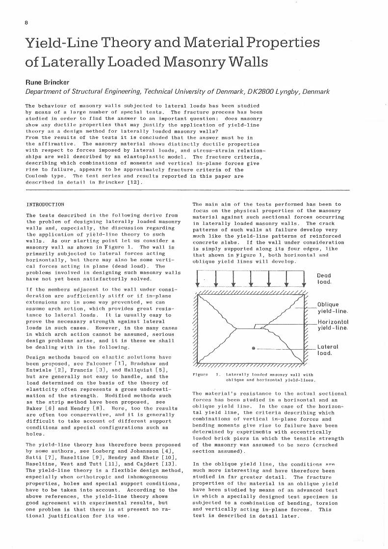
The main aim of the tests performed has been to focus on the physical properties of the masonry materlal against such sectional forces occurring in laterally loaded masonry walls. The crack patterns of such walls at failure develop very much like the yield-line patterns of reinforced concre te slabs . If the wall under consideration is simply supported along its four edges, like that shown in Figure l, both horizontal and oblique yi e ld lines will develop.
Figure
DL> ad load.
Oblique yield-line.
r---,..L------17--H o r i z o n t at r----''--'"'-.. yield - ti n e.
1. Lnternlly l on<lcd ma sonry wnll with o blique and h or i zontal yield-lines.
Lateral load.
The material's resistance to the actual sectional forces has been studled in a he rizental and an oblique yield line. In the case of the horizon~
tal yield line, the criteria describing which cernb inations of vertical in-plane forces and bending moments give rise to failure have been determined by experiments with eccentrically loaded brick piers in which the tensile strength of the masonry was assumed to be zero (cracked section assumed).
In the oblique yield line, the conditions ~rP.
much more interesting and have therefore been st udi ed in far greater detail. The fracture properties of the materi a l in an oblique yield have been studied by me ans of an advanced test in which a specially designed test speelmen is subjected to a cernbination of bending, torsion and vertically acting in-plane forces. This test is deseribed in detail later .
In the programme tests were performed on four combinations of materials, two qualitles of mortar and two types of brick. The bricks were Danish normal size 55x108x228 mm; one of them was solid , while the other had 55 holes distri buted in five rows parallel with the Iongest edge of the brick . The solid brick had a compression strength of 48 MPa, and the brick with holes a compression strength of 28 MPa . Thø two mortars werc both rclatively weak. One was a pure lime ~ortar with a l ime/sand ratio of 100/1200 (uy weight), and the other was a lime-cement mortar, with a lime/cement/sand ratio of 50/50/750. The compression strengthof the rnortars, determined by means of 40x80 cylindrical mortar specimens, was found to be 1 . 0-1 . 7 MPa for the lime mortar and 3.0-5.2 MPa for the lime-cement mortar. The four combinations of materiais have each been given a code as shown in Table l .
Solid Brick
brick witli holes !
. M<n:tar: Lime/sand: L-S L-H 100/1200 (by weight)
Mortar: Lime/cement/sand: L C-S LC-H 50/50/750 (by weight)
TABLE l - CODE NUMBERS AND COMBINATIONS OF MATERIALS USED IN THE TEST PROGRAMME
TESTS RELATED TO HORIZONTAL YIELD LINES
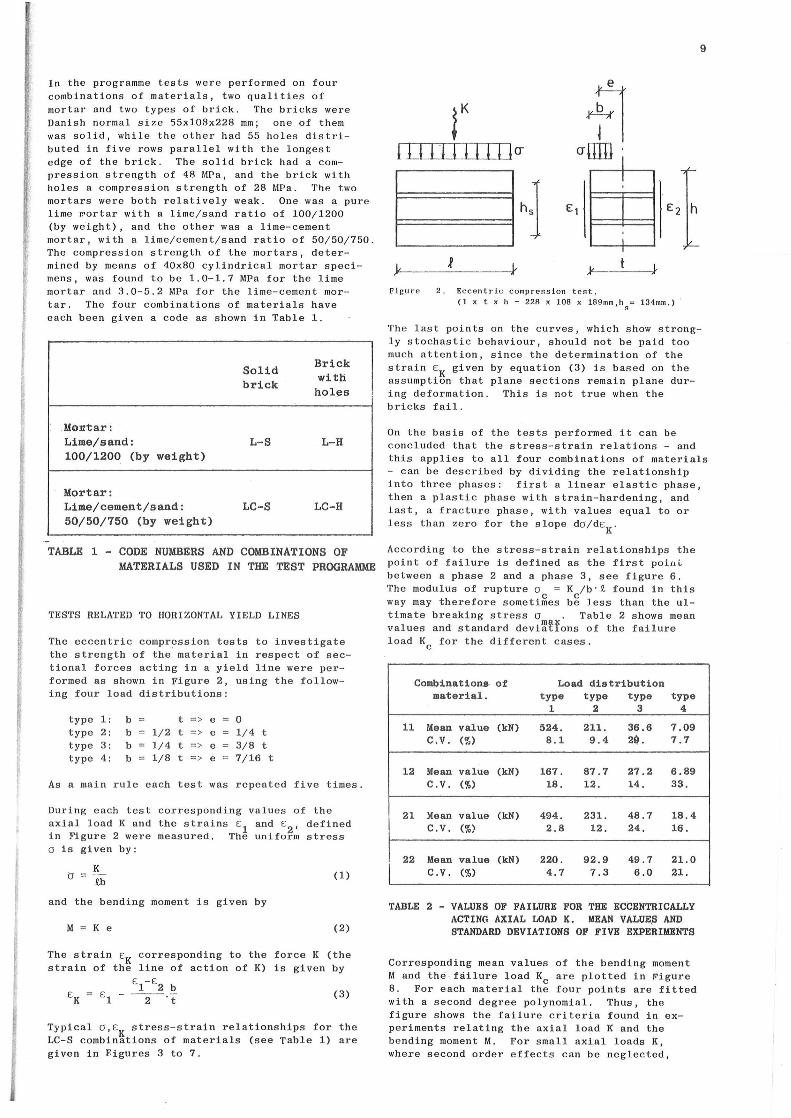
The eccentric compression tests to investigate the strength of the materla l in respect of sectional forces acting in a yield line were performed as shown in Figure 2, using t h e foliowing four load distributions:
type 1: b t => e o type 2: b 1/2 t => e = 1/4 t type 3: b 1/4 t => e = 3/8 t type 4: b 1/8 t => e = 7/16 t
As a main rul e each test w as repeated five times .
During each test corresponding values of the axial load K and the strains €
1 and E
2, defined
in Pigure 2 were measured. The unifo rm stress a is given by:
K a = .Q.b
a nd the bending moment is given by
M = K e
(l)
(2)
The strain €K corresponding to the force K (the strain of the line of action of K) is given by
El-€2 b €K = El - -2-'t (3 )
Typical O,€K stress-strain relationsbips for the LC-S combinations of materiais (see Table l) are given in F.igures 3 to 7.
J }-------
e
-Fl arrm ' l !
e: 1 l l
Flgure 2. Eccentric compression t es t. (l x t x h = 22R x 108 x 1R9mm,h
8= 134mm.) ·
9
The last points on the curves, which show strongly stochastic behaviour, should not be paid too much attention, since the determination of the strain EK given by equation (3) is based on the assumption that plane sections remain plane during deformation . This is not true when the bricks fail .
On the basis of the tests performed it can be concluded that the stress-strain relations - and this applies to all four combinations of materiais - can be deseribed by dividing the relationship into three phases: first a linear e lastic phase, then a plastic phase with strain-hardening, and last, a fracture phase, with values e qual to or l ess than zero for the slope do/d€K.
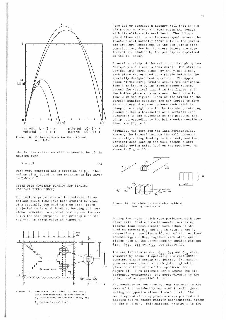
According to the stress-strain relationsbips the point of failure is defined as the first poinL between a phase 2 and a phase 3, see figure 6. Th e modulus of rupture oc = Kc/b • .Q. found in this way may therefore sametimes be less than the ul timate breaking stress om ~· Table 2 shows mean values and standard deviaf1ons of the failure load Kc for the different cases .
Combinatiana o f Load distribution material. type type type type
l 2 3 4
11 !.Iean value (kN) 524. 211. 36.6 7.09 c.v. (%) 8.1 9.4 21). 7.7
12 Mean va1ue (kN) 167. 87.7 27.2 6.89 c.v. (%) 18. 12. 14. 33.
21 Mean value (kN) 494. 231. 48.7 18.4 c.v. (%) 2.8 12. 24. 16.
l 22 Mean value (kN) 220. 92.9 49 . 7 21.0
c.v. (%) 4.7 7.3 6.0 21.
TABLE 2 - VALUES OF FAILURE FOR THE ECCENTRICALLY ACTING AXIAL LOAD K. MEAN VALUE,S AND STANDARD DEVIATIONS OF FIVE EXPERIMENTS
Corresponding mean values of the bending moment M and th~ fdilure load Kc are plotted in Figure 8. For each materlal the four points are fitted with a second degree polynomial . Thus, the figure shows the failure criteria found in experiments relating the axial load K and the bending moment M. For s mall axial loads K, where second order effects can be neglected,
10
25
er IMP a )
0
l l
L l
+ ,t
+ .t z
i/ l l ...---o
++i
,t : ff +" i
i
! .,.., !
-l' ''·, i l ~ l l .r
i ;, ,, l ;-
: l ! +
'.. l .,. l
l l l l
20
Figurø J. Matertal combination LC -S, ioad distribution type l.
_j 20~~~--~~--~~'~/
/ : J
/V er
IMPa)
/:
'( 0~--~--~---L--~--~--~
n IO Ei<1%a l
Figure 5. Materlal comhination LC-S load distribution type 2.
1 J
O" IMPa )
o
f L f
o
+......_ ........
-~
20
er IMPa
er c
)
25
l t:
t! 1 _[~ 1 O"
IM Pa ) y l A
F+ _t_ i
:t J o o
rr .JI. ff
/
J s
l
+ l +
++
i++ i
L IL
/ ~ c O
Figure 4. The load relieved three times.
i
++- '+ t-+-+ 1-+
#+ +f+-++
.,.,.,. l l l
/ 'l
o o IO
Figure 6. Materlal combination LC-S load distribution type 3.
l
i l
25 Figure 7 . Materlal cernbination LC-S load
distri bu tion type 4.
Figures 3 - 7 Stress relationship for eccentric compression tests.
l l
5
M l kNm)
mater ie l L materie l L
s H
+ materie l maler i al
LC - S LC - H
Figur·e R. Fnilure critcrla for the diffcrent mat0rtnls.
• '
the failure eriterion will be seen to be of the Coulomb type:
(4)
with zero cohesion and a frietion of ~ . The values of W found in the experiments ~re given in Table 8.
0
TESTS WITH COMBINED TORSION AND BENDING (OBLIQUE YIELD LINES)
The failure properties of the material in an oblique yield line have b een studled by means af a special ly designed test an small piers s ubjected to lateral loading, bending and torsianal moment s . A special testin g machine was built for this purpose. The principle af the test-bed is illustrated in Pigure 9.
9. The mec l1nnic.al principle for tests witl1 cernbined bending and torsion. K
2 corresponcts to the dead load 1 and
K1
to th e lateral land.
Here let us consider a masonry wall t h at is simply supported along all four edges and loaded wit h its ultimate lateral load. The oblique yield lines will be staircase-shaped because the fracture will normally occur only in the joints . The fracture conditions af the bed joints (the contributions due to the cross joints are neglected) are studled by the principles explained in the following.
A vertical strip of the wall, cut through by two oblique yield lines is considered . The strip is divided into three pieces by the yield lines, each piece represented by a single brick in the specially designed test specimen. The upper piece af the strip rotates araund the horizontal line l in Pigure 9, the middle piece rotates araund the vertical line 4 in the figure, and
11
the battom piece rotates araund the horizontal line 2 in the figure. Each of the bricks in the torsion-bending speelmen are now forced to mave in a corresponding way because each brick is clamped to a rigid arm in the test-bed, rotating araund either a horizontal ar a vertical line according to the movements af the piece of the strip corresponding to the brick under consideration, see Figure 9.
Actually, the test-bed was laid horizontally, whereby the lateral load an the wall became a vertically acting load K1 in the test, and the vertical dead load on the wall became a hori zontally acting axial load an the specimen, as shown i n Figure 10.
...!.'
[IJD
---""
Fi~LirP 10. Pz·incipJc for tests with cernbined bending a nd torsio ~.
l•·•oe i<
During the tests, which were performed with constant axial load and continuously increasing lateral load, measurements were taken af the bending moments M11 and M21 in joint l and 2, res pectively , see Figure 10, and af the torsional moments M1 2 and M22 , together with other quantities such as the corresponding angular strains
~ 11• ~21• ~ 12 and ~ 22 , see figure 10.
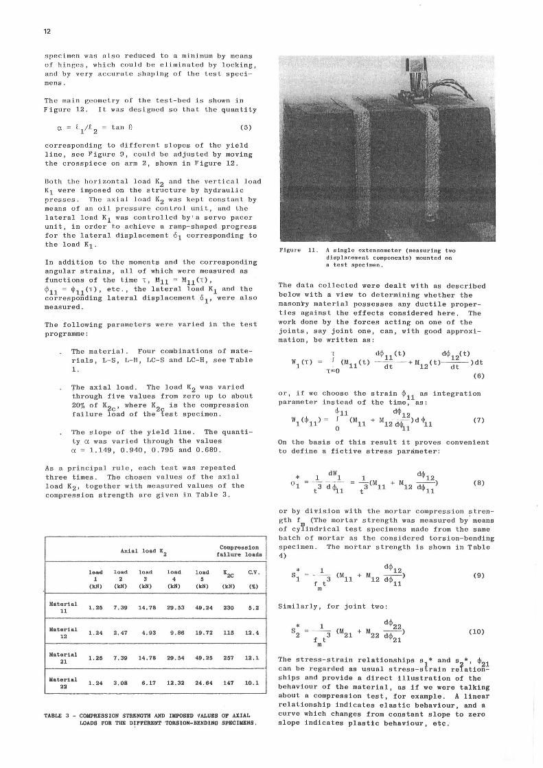
The angular strains ~ 11 , ~ 21 , ~ 21 and ~ 22 were measured by means of specially designed extensometers placed across the joints. Two extenso~eters were placed at each joint, glued in place an either side af the specimen, see Figure 11. Each extensometer measured two dis piacement components: ane perpendicular to the joint, and ane parallel to it.
The bending-torsion speelmen was fastened to the arms af the test - b e d by means af frietion jaws actinc an opposite sides af each brick. The mounting and starting ~rocedure was planned and carried out to ensure minimum unintentional stress in the specimen. Unintentional prestress in the
12
specimen was also reduced to a minimum by means of hinges, which could be eliminated by locking, and by very accurate shaping of the t es t specimens.
Th e main geometry of the test-bed is shown in Figure 12. It was designed so that the quantity
(5)
corresponding to different slopes of the yield line, see Figure 9, could be adjusted by moving the crosspiece on arm 2, s hown in Figure 12 .
Both the horizontal load K2 and the vertical load K1 were imposed on t he structure by hydrauli c presses. The axial load K2 was kept constant by means of an oil pressure control unit, and the lateral load K1 was controlled by ' a servo pacer unit, in arder to achieve a ramp-shaped progress for the lateral dispiacement ol corresponding to the load K1.
In addition to the moments and the corresponding angular strains, all of which were measured as functions of the time 1, M11 = M11 (1), ~ll = ~ 11 (1), etc., the lateral load K1 and the corresponding lateral dispiacement o 1 , were also measured .
The foliowing parameters were varied in the test programme:
The material . Four combinations of materiais, L-S, L-H, LC-S and LC- H, see T ab le l.
The axial load. The load K2 was varied through five values from zero up to about 20% of Kzc• where K2 is the compression failure load of the fest specimen.
The slope of the yield line . The quanti ty a was varied through the values a= 1.149, 0.940, 0 .795 and 0.689.
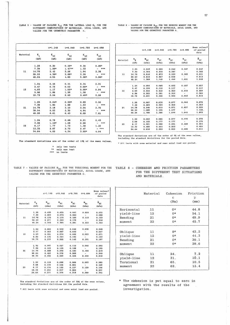
As a principal rule, each test was repeated three times . The chosen values of the axial load K2 , together with measured values of the compression strength are given in Table 3.
Axial load K2 Compression l
taUure loadø 1
load load load load load K2C c.v. l 2 3 4 5
(kN) (kN) (kN) (kN) (kN) (kN) (~)
Materi al 1.211 7.39 14.78 29.53 49.24 230 5.2 11
liatertal 1.24 2.47 4.93 9 . 86 19.72 115 12.4
12
Materi al l. 211 7.39 14 . 78 29.54 49.25 2117 12.1
21
liatertal l. 24 3 . 08 6.17 12.32 24 .. 64 147 10 . 1
22
TABLE 3 - COIIPRESSION STRENGTH AND IKPOSED VALUES OF AliAL LOADS FOR TUE DI!'FERENT TORSION-BENDING SPECIIIEHS.
Figure 11. A singl e extensometer (mea s uring two dispiacement components) mounted on a test speci men.
The data collected were dealt with as deseribed below with a view to determining whether the masonry material possesses any duetile properties against the effects considered here . The work done by the forces acting on one of the joints, say joint one, can, with good approximation, be written as:
or, if we choose the parameter instead of
<j,ll wl <~11> = 1 <M11
o
strain ~ll as integration the time, as:
d~l2 + Ml2~)d <j>11 (7)
11
On the basis of this result it proves convenient to define a fictive stress paråmeter :
(8)
or by di*i sion with the mortar compression strength f (The mortar strength was measured by ' means of cyTindrical test specimens made from the same batch of mortar as the considered torsion-bending specimen. The mortar strength is shown in Table 4)
(9)
Similarly, for joint two:
(lO)
The stress- strain relationsbips s * and s *, ~
can be regarded as usual stress-s~rain re~atio~! ships and provide a direct illustration of the behaviour of the material, as if we were talking about a compression test, for example. A linear relationship indicates elastic behaviour, and a curve which changes from constant slope to zero slope indicates plastic behaviour, etc ;

If we could impose on t h e stru cture precisely the dispiacement field wanted , we would have:
(l l)
whic h mean s t h at the relationship betwee n t h e torsianal and the beodine angular strain for both joi n ts s h ould be linear.
In practice, of course , t h e i mposed disp i acement field will always show a certain deviation from the intended field. In order to see how good agreement t h ere was betwee n t h e t h eoretical a n d the imposed dispiacement field, the measured bending a n gular strain was for both joints p l otted agai nst the measured torsional angu l ar strain, together with the i n tended relation s h ip indicated by a straight li ne. A typica l res u lt is s h own in
igure 13. As will be seen, the agreement between t h e theoretical and t h e i mposed dispiacements was best in the latter part of the test.
Th e stress-strain re l at i onsbips s1
* , ~ll and s~*, ~ 21 for t h e same test are shown in figure 14, oget her wit h the contributions 6s
1* and 6s 2 * due
to bending alone.
l --3 Mll f t
m
l --3 M21 f t
m
( 12)
As will be seen from the figure, the materlal showed distinctly plastic behaviour.
Finally, for the same test, Figure 15 shows the lateral load K1 , plotted against the corresponding di s placgment ol.
The results shown here can generally be considered as representative of all the tests, although there was a tendency for tests with lower values of the axial load K2 to result in mor e irregular curves (data showing greater deviations from the mean trend), and vice versa i n cases of higher values, where the curves are even more regular. However, the general t e ndency is clear enough: all stress-strain relationsbips show distinctly plastic behaviour, as illustrated by th e test shown in Figure 14 . With respect to the imposed deformations, these seem to be in agreement with the intended deformations only in the latter part of the test, when fracture had comp}etely developed, bec a~se the test specimens possessed considerable
r es istance to torsional strain in the early stages of fr ac ture. On the basis of the relationsbips obtain e d, fail u r e values for the la
teral load Klc and for t h e mo ments Mllc' M12 , ri d 11 together w i t h t h e failure benåina '2lc an ·' 22<;:' "' angu l ar stra1n ~c• were determined for all tests.
The failure strain ~c was determined as t h e mean value of the bending angular strai n s for the two joints, correspondin~ to the kink-point in the elastopløstic approxi mation of the measured stress-strain relationships . No dependeuc: t: on the geometrica l parameter a could be traced; therefore , all the failure strains corresponding to t h e same materlal and the same axial load have be e n pooled. T he results obtained are shown in Figure 16. Here, the failure strains are plotted against the stress level K2/K2c• where K2 is the actual axial l oad, and K2 c is
the compression failure load. It will be seen that with the data d epicted in this way , there seems to be no depen d ence on the c hoice of material , but- with good a p proximation-
13
l i neai dependence o n the axial load. However, the most important aspects of the tests reported here are t h e valuation of t h e meas u red fai l ure
o o M
800
r --·-~
arm Q}
IPE 120
RHS 120•60•5
t~ A X lAL . LOAD K,
l 1100
ALL MEASURES IN mm.
r,
Figll rc 12 . The mai n g e omctr·y of thc t es t bed.
10
'P• 2 (%o)
o o ~
d D-D-
JOINT l JOINT 2
/ / / . . ---
•
• -' /'
// / -· ·~ / _./
,L-
...---::: / ~ Q/
___ .v . ...-
Flgure 13. Torsional angular strai n plotted ngainst t l1 c bending angular strains for t l1e LC - ff combination of materiale witl1 K
2 = 12.32 kN, and n = 0. 9•;G ,
V:: m-' v
r---
--
10
20 ,----,----.- ·-- --=-- ,--·..,-----,----· ....__.,. _ _ "r-- ... --·- - ...
S; (% ) ....
f-- +----.A'---+---f---l·---r--- f-- ·--1-v/•
f-----+~-4--~~~=+~~--~~--·----rc--··-~~--t--=~~~~ v .. __. •-r-· r----f --J-"'---- 1-- -1---+-- ---.------ l-l J "./ ~x· _.;,( ->-~- x-- -~-- x r-:1.'-+ .. --r--;. "'.c-:~:l>o--L"-1_r-' ... =_"'f-~-_--.; !---+- .--::: .... .-===4·.-==-f-=-r..,l-'"''+-+ -~f!:=----... -t----t---+--·+- - -1--+----1-- --J . ., ..........
i ......
ti/ 11-+---+-l---lf-------- . ---+--+--t---1 lif---j---+----+--+----+--+----- :---··-·--r-·--·
- · o~-~-~-~--~-~--
0 <j) ,J(%o) 10
A • JOI Il T 2 + • JO l N l 2
Pigure 14. Stress - strain r e lationships sr rfl11
nn d S~, ~ 21 toget il e r wlt h t h e
contributtons from bending alone for the LC-H comb in ation of ma·terial wi th K
1 = 12.32 kN, and et= 0.910.

14
K 1(kN)
3
2
2
Tes~ stopped.
5, ------L--------L----
3 1. (mm)
Figure 15. SimultRneolJS plot of the lat e t·al load K
1 v. lat e ral dispiace ment 6
1 for
5
4>c (%o)
f
the test s hown in Figures 13 and 14,
Materiel L - S + Mater i ol L. - H x Materiel LC- S A
Materiel LC- H v
Figure 16. The depenrlenc e of the fa i lu re strain upon the s tre ss l e vel R2 ;K 2c .
+
value s for the lateral load and the bending and torsional moments, and their dependence upon the mat erial, the axial lo ad , a nd the geometrical parameter a representing the slope of oblique yield lines .
It is not difficult to see that the masonry material can b e ascribed two yield moments based on th e ideas and results given here c haracterising the ability of the material to resist lateral loading - a nd this is essential if we wi s h to apply th e yield lin e theory in the usual way - only if th e failure values for the bending and torsional moments measured by the tests can be assumed to be independent of the geometrical parameter a.
In faet, this seems to be the case. The tests show that if th ere is any dependence on a at
all for the values of a considered here, it is at any rate weak and of minor significance. It can be neglected, and we have therefo rA rnnled all data corresponding to the same material and the same axial loa d. Readers who are interested in further investigations regarding this assumption are referred to the test report Brincker [12] . The reasonableness of the assumption can be checked by applying the pooled failure values for the b e nding and torsional moments to obtain a plastic solution for the dependence of the lateral load K1 on the geometrical parameter a, and comparing this result with the measured failure values for the lateral load . All the data required can b e obtained from Tables 5, 6
Mater i ol L S Malerial L - H Materiet LC- S Materiel LC - H
x A
'
Figure 17. Fail ure criteria for dlff e rent mat e rlal s.
'
and 7, giving th e results of th e measured failure values for th e lateral load and th e moment s . This investiG a tion - which serves to s upport the assumption - is also performed in the repart Brinck e r r 12l .
In Pigures 17 and 18 th e failur e values fer the bending moments and the torsional moments are eac h plotted against th e axial load . The figures s how the failure criteria for the diffcrent materia l s for b e nding and torsion meas ured by the t es ts . These curves are one of themost important res ult s of the test programme .
The meas ured failure criteria for the b endi ng mome nt s can be d eseri bed in the foliowing way. For sma ll values of the axial load, K2 , th e criteria seem to be the same, independent of the choi ce of material, a nd the criteria are all of the Coulomb type with zero cohesion. For h igh er values of K2 (v a lues of K
2 greater
than, say, 10% of the compression strength), second order effects reduce the failure values for the bending moments compared with the extrapolated linear behaviour found for s mall values of K2 .
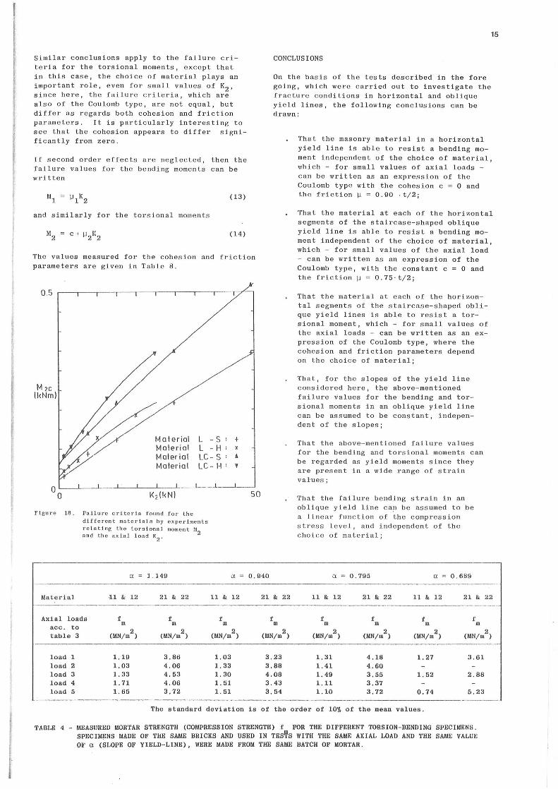
15
Similar conclusions apply to the failure criteria for the torstonal moments, except that in this case, the choice of materlal plays an important role, even for small values of K2 , sinc e here, the failure criteria, which are also of the Coulomb type, are not equal, but differ as regards both cohesion and frietion parameters. It is particularly interesting to see that the cohesion appears to differ significantly from zero.
I f second orde r effec t s a re neglected, t hen the Iailure values for the bending moments can be written
(13)
and similarly for the torsional moment s
(14)
The values measured for the cohesion and frietion parameters are given in Table 8.
os
Flgur e 18.
Materiel Materi al Materie l Materia l
L - S L - H LC - S LC - H
Fatlure crite ri a found for th e dif fe re nt mate ri a is by ex pe rim e nt s rel nting th e torstonal mo ment M
2 and th e axial load K2
.
+ x A
'
CONCLUSIONS
On the basis of the tests deseribed in t h e fore going, which were carried out to investigate the fracture conditions in herizental and oblique yield lines, the following conclusions can be drawn:
That the masonry materlal in a herizental yield line is able to resist a bending moment independant of the choice of material, which - for small values of axial loads -can be written as an expression of the Coulomb type with the cohesion c =O and thc frietion W = 0.90 ·t/2;
That the material at each of the herizental segments of the staircase-shaped oblique yield line is able to resist a bending moment independant of the choice of material, which - for small values of the axial load - can be written as an expression of the Coulomb type, wit h the constant c = O and the frietion ~ = 0.75 · t/2;
That the materlal at e ach of the horizantal segments of the staircase-shaped obli que yield lines is able to resist a torsianal moment, which - for small values of the axial loads - can be written as an expression af th e Coulomb type, where the cohesion and frietion parameters depend on th e choice of mat e rial;
That, for th e s lopes of the yi e ld line considere d here , the above-mentioned failur e values for the bending and torsianal moments in an oblique yield line can b e assumed to be c onstant, independent of the slopes;
That th e abov e -mentione d failur e values for the bending and torsional moments c a n be r e garded as yield moments since they are pre s ent in a wide range of strain val·u es ;
That the failure bending strain in an oblique yield line ca~ b e assum e d to be a line ar fun c tion of th e compre s s ion stre s s level, a nd inde p e ndent o f the choic e of mat e rial;
a l. 149 a 0.940 a 0.795 Cl. = 0.689
Material 11 & 12 21 & 22 11 & 12 21 & 22 11 & 12 21 & 22 11 & 12 21 & 22
Axial loads f f f f f f f f m m m m m m m m acc. to
(MN/m2
) (MN/m2
) (MN/m2
) (MN/m2
) (MN;m2
) (MN/m2
) (MN/m2
) (MN/ru2
) table 3
--
---·-----------
load l 1.19 3.86 1.03 3.23 1.31 4.18 l. 27 3.61 load 2 l. 03 4.06 l. 33 3.88 l. 41 4 . 60 load 3 l. 33 4.53 l. 30 4.08 l. 49 3.55 l. 52 2 . 88 load 4 1.71 4 . 06 l. 51 3.4:J 1 . 11 3.37 load 5 l. 65 3,72 l. 51 3,54 1.10 3.72 0 . 74 5.23
The standard deviation is of the orde r of 10% o f the mean values.
TABLE 4 - MEASilRED MORTAR STRENGTH (COMPRESSION STRENGTH) f FOR THE DIFFEI!ENT TORSION-BENDING SPECHIENS . SPECIMENS MADE OF THE SAME BRICKS AND USED IN TEs'l\s WITH THE SAME AXIAL LOAD AND THE SAME VALUE OF a (SLOPE OF YIELD-LINE), WERE MADE FROM THE SAME BATCH OF MORTAR.
16
That second order effects, which reduce the failure values for the moments in both horizontal and oblique yield lines, should be taken into account in cases of greater values of the axial loads.
All things considered, it can be concluded that the results of the investigation support the application of yield-line theory as a design method for laterally loaded masonry walls.
Nevertheless, it must be admitted that the inves tigation and its results aremore of a qualitative than a quantit~v& nature, and even though we have supported the assumption that masonry walls do possess some duetile properties against lateral loads that may justify the use of yield
REFERENCES
[l] B.H.Falconer (1962) . Engineering design in brickwork. Clay Produets Bulletin, New Zealand Pottery and Ceramics Research Association (PACRA), Publ. No. 22 .
[2] R.E . Bradshaw and F.D . Entwisle (1965) Wind forces on non-loadbearing brickwork panels. Clay Produets Technical Bureau, Techn . Note, l (6), London, 8pp.
[3 ] A. J . Francis (1964) The SAA Brickwork Code - The research background. The Civil Engineering Transaetions of the Institute of Civil Engineers, Australia, pp. 165- 176.
[4] A.Losberg and S . Johansson (1969) Sidewavs pressure on masonry walls of brickwork. CIB Symposium on Bearing Walls, War saw .
[5] A. Hallquist (1970) Lateral loads on masanry walls. Norwegian Building Research Institut e (NBI). Reprint No. 172 . Oslo .
[6] L . R . Baker (1972) Brickwork panels subjected to face wind loads . Thesis for degree of Master of Engineering Science, University of Melbourne, 20 4 pp .
[7] K. M. H. Satti (1972) Model brickwork pane ls under lateral loading . Ph . D. thesis, Edinburgh .
line theory, the results are limited by si~~li fying points of view, as for instance the faet that we ignore the contributions to the lateral strength due to the cross joints .
However, this does not weaken the main results of the investigation, which prove that laterally loaded masonry walls do have duetile properties, and prove that - and explain why - the oblique yield lines greatly increase the lateral strength of such walls, especially in cases of small values of the in-plane forces.
ACKNOWLEDGEMENTS
Financial support from the Danish Council for Scientific and Industrial Research is gratefully acknowledged.
[8] A.W . Hendry (1973) The lateral strength of unreinforced brickwork . The Structural Engineer, pp. 43-50.
[9] B. A. Haseltine (1974) Design of lateral1y loaded wall panels. Proc . Fifth Symposium on Loadbearing Brickwork, British Cer. Soc., London, pp. 115- 126.
[10] A. IV . Hendry and A. M.A. Kheir (1976) The lateral strengthof certain brickwork panels. Proc . Fourth Int . Drick Masonry Conf, Brug~e.
[11] B.A. Haseltine, H.W. West and J.N . Tutt (1977) Design of walls to resist lateral loads . The Structural Engineer, October 1977, 55 (10) pp . 422-430.
[12] R . Brincke r (1979) Th e lateral strength of masonry walls . An inve stigation of the physical properties of masonry . (In Danish) Structural Research Laboratory, Technica1 University of Denmark, Report No . R111, 210 pp.
[1 3 ] A. Cadjert (1980) Laterally loaded masonry walls . Ph.D . thes is, Chalmers Unive rs ity of Technology, Div . Conc . Struct., Publ. 80 : 5, Got eborg, pp . 283.
1
l
TAliLE 5 - VALURS OF FAILIIRE S:tC !'Oll TI!K !J.Tl!llAL LOAD Kt FOR l'llli:
liatertal
ll
12
21
22
DIF!'l!RENT COIIBiliATIONS OP liATBil I ALS. UIAL LOADS, Alfll V ALUJ!S ro a 'r!l& GEOKETRIC PARAllnEll o:.
Gt•l.l49 aDI0,94.0 a•O. 79~ CL•0 . 689
K1 11c K1C K1C K1C
(klO (klO (klO (klO (k.'i)
1.25 0 .30 0.32• 0.30 0.2$• 7 . 39 1.56• l. 47** 1.33 - ...
U;78 2 . ~ 2.56 1.84 2.38 29.53 4. 38• 3.66* 3.35 - ... 49.24. ;.;$5 4.8$ 5. 26• 5,$8*
1.24 0 .45 0 . 41 0.34 0 .'31 2 . 47 o. 75 0.63 0.60• - ... 4.93 1.17 1.05* 0.95• 0.94 9.86 1 . 89 l. 38 l. 58 - .....
19.72 3 . 24 2.os 2.40• 2.$9
1.25. 0 . 64• 0.50 .. · 0 . 62 o.so 7 . 39 l. 80 l. 88 l. 53 - ...
14.78 3.18 3 .10 2.64 2.70 29 . 54 5. 53 5. 30 4. 84 - ... 49.25 8.61 6.43 8.69 7.61
1.24 0.78 0.68 0.51 0.43 3.08 1 . 19*· 1.08 0.96 - ... 8.17 1.77 l. 73 l. 32 l . 30
12.32 2 . 87 2.. 70 2.47 - ... 24.64 4.95 4 . 34 3.9$• 4.04
The standard deviations are ot the arder ot 13~ ot the maan valuea.
:.>nly two tests only one te a t
••• :to tests
TADLE 6 - VALUES OF FAILURE MlC FOR THE BENDING MOMENT FOR THE DIPYERENT COMBINATIONS OF IIATERIALS, AXIAL LOADS, AND VALUES FOR TIIE GEOilETRIC PARAMETER a.
17
U e an vslues• U'-"1.149 a=O. 940 o~o. 795 Cl=O. 689 ol pooled
data
Moterial K2 111c MIC 11
tc 11
1c MlC
(kN) ( k~m ) (kNm) (kNm) (kNm) (kNm)
l. 25 o. 043 0.060 0 . 044 o. 047 0.047 7. 39 o. ~04 o 330 o. 287 - o. 300
11 14.78 o. ~16 0 . 573 o. ~33 o. 582 o. 551 29,53 o. 919 o. 867 o. 939 - o . 913 49. 24 l. JOB l. 140 l. 449 l. 621 1 . 34B
~·--- ---·-------------l. 24 o .0~4 o. 068 0.052 o . 057 0.057 2. 47 0 .124 0.110 0 . 117 - 0 . 117
12 4. 93 o. 204 o. 212 o . 203 0.210 o. 208 0.86 o . 353 o. 391 o . 352 - o .306
19.72 O.OH 0.500 o . 589 o. 653 0.615
1. 2~ 0.067 0.070 0 . 077 0 . 064 0.070 7. 39 o. 284 0.324 o . 302 - o. 303
2t 14.78 o. ~40 o. 61~ o . 571 o. 607 o. 583 29.54 1 . 08~ 1.125 1.177 - 1.129 . 49.25 l. 789 1. 390 l. 648 1. 942 1. 683
1. 24 0.053 0.095 o. 077 0 .076 0.079 3 . 08 o. 152 0.177 o. 177 - o. 170
22 8.17 o . 261 o. 280 o. 2~1 o. 258 o. 264 12 . 32 o. 48~ o. 405 o. 503 - o. 495 24.64 0.916 o. 058 o. 866 0.989 0.90
The standard deviations ar e o t the orde r of 51, o f tbe mean v aloes, Ineludine the øtandard devlnttoua tor the pooled data.
• AJl te ~t t.ø with ll!llltae 11atortal and øam~ axlal load are pool~d.
TABLE 7 - VALUES OF FAILURE M2c FOR THE TOilSIONAL MOMENT FOR THE TABLE 8 - COHElSION AND FRICTION PARAMETERS DIFFERENT COMBINATIONS OF MATERIALS, AXIAL LOADS, AND . FOR THE DIFFERENT TEST SITUATIONS VALUES FOR THE GEO!lliTRIC PARAMETER a.
Mean valueø• <l"" l. 14Q (1 1:1 9,010 a::tO. 79 5 <1•0.689 ot poolf)d
data
Matertal k2 M 2C
112c M2C 11
2c jj2C
(kH) (kHM) (kHm) (k NM) (kNe) (kNa ) ----------·-·
1. 25 0.029 0.025 0.041 0.02~ 0.031 7. 39 o. 094 0.072 0.092 0.089
11 14'. 78 o. 13~ o. 135 0.109 0.115 0.123 29.53 o. 271 o . 225 0.178 o. 218 49. 24 o. 342 o. 395 o. 281 o. 33~ o. 344
----------- -·--------·--·-·--------1. 24 o. 055 o. 042 0.046 0.036 o. 04~ 2. H o. 062 o. 057 0.0~0 0.057
12 4. 93 o. 091 o. 070 0.066 0.062 0.071 9. 86 o. 1~5 o . 124 0.129 0 . 129
19 72 o. 233 o. 205 o .143 0.151 0.187
1.15 o. 087 o .067 0.110 O.M6 o. 082 7.39 o. IG3 0.125 0.128 0.180
21. 14. 78 o. 268 o. 2'0 0 .180 0.194 0.218 29. 54 o. 102 o . 379 o. 269 o . 348 49. ?.5 O. SAO o. ~90 0.455 o. 459 o . 516
1. 24 o. 118 0.088 0.069 0 . 053 0.082 3. 08 o. 139 0.10~ 0.091 0.108
22 R . 17 o. 176 o . 182 0.127 0.129 0.146 12.32 o 250 o . 237 o. 205 o. 231 24 . G4 o. 377 o . 378 o. 318 o . 209 o . 345 ----- ,., _____ --
The øtandnrd cteoviøt ton~ ar e o t the orde r o f 10$ ol the mean va1ues, lncludt ng t he eta ndnrd ch!\' .tl\ttons fcSr :.the pooled fh.ta.
• All tesf:P with Rl\me mntertal and I!IIU!Ie axtal load nre pooled.
AND MATERIALS .
Materi al Cohesion Frietion c \l
(N m) (mm)
Horizontal .11 O* 44.8 yield-line 12 O* 54.1 Bending 21 O* 49.9 moment 22 O* 45.7
Oblique 11 O* 42.2 yield-line 12 O* 44.3 Bending 21 O* 39 . 1 moment 22 O* 38.6
Oblique 11 24. 7 . 2 yield-line 12 31. 10 . 1 Torsional 21 65. 10.5 moment 22 62. 15.4 _____ .. ____
* The cohesion is put equal to zero in agreement with the results of the investigation.