Aalborg Universitet Shadow Detection in Dynamic …vbn.aau.dk/files/36513580/d3dicameraready.pdf ·...
17
Aalborg Universitet Shadow Detection in Dynamic Scenes Using Dense Stereo Information and an Outdoor Illumination Model Madsen, Claus B.; Moeslund, Thomas B.; Pal, Amit; Balasubramanian, Shankar Published in: Lecture Notes in Computer Science DOI (link to publication from Publisher): 10.1007/978-3-642-03778-8_9 Publication date: 2009 Document Version Publisher's PDF, also known as Version of record Link to publication from Aalborg University Citation for published version (APA): Madsen, C. B., Moeslund, T. B., Pal, A., & Balasubramanian, S. (2009). Shadow Detection in Dynamic Scenes Using Dense Stereo Information and an Outdoor Illumination Model. Lecture Notes in Computer Science, 5742, 110-125. DOI: 10.1007/978-3-642-03778-8_9 General rights Copyright and moral rights for the publications made accessible in the public portal are retained by the authors and/or other copyright owners and it is a condition of accessing publications that users recognise and abide by the legal requirements associated with these rights. ? Users may download and print one copy of any publication from the public portal for the purpose of private study or research. ? You may not further distribute the material or use it for any profit-making activity or commercial gain ? You may freely distribute the URL identifying the publication in the public portal ? Take down policy If you believe that this document breaches copyright please contact us at [email protected] providing details, and we will remove access to the work immediately and investigate your claim. Downloaded from vbn.aau.dk on: august 31, 2018
Transcript of Aalborg Universitet Shadow Detection in Dynamic …vbn.aau.dk/files/36513580/d3dicameraready.pdf ·...

Aalborg Universitet
Shadow Detection in Dynamic Scenes Using Dense Stereo Information and an OutdoorIllumination ModelMadsen, Claus B.; Moeslund, Thomas B.; Pal, Amit; Balasubramanian, Shankar
Published in:Lecture Notes in Computer Science
DOI (link to publication from Publisher):10.1007/978-3-642-03778-8_9
Publication date:2009
Document VersionPublisher's PDF, also known as Version of record
Link to publication from Aalborg University
Citation for published version (APA):Madsen, C. B., Moeslund, T. B., Pal, A., & Balasubramanian, S. (2009). Shadow Detection in Dynamic ScenesUsing Dense Stereo Information and an Outdoor Illumination Model. Lecture Notes in Computer Science, 5742,110-125. DOI: 10.1007/978-3-642-03778-8_9
General rightsCopyright and moral rights for the publications made accessible in the public portal are retained by the authors and/or other copyright ownersand it is a condition of accessing publications that users recognise and abide by the legal requirements associated with these rights.
? Users may download and print one copy of any publication from the public portal for the purpose of private study or research. ? You may not further distribute the material or use it for any profit-making activity or commercial gain ? You may freely distribute the URL identifying the publication in the public portal ?
Take down policyIf you believe that this document breaches copyright please contact us at [email protected] providing details, and we will remove access tothe work immediately and investigate your claim.
Downloaded from vbn.aau.dk on: august 31, 2018
Shadow Detection in Dynamic Scenes Using
Dense Stereo Information and an OutdoorIllumination Model
Claus B. Madsen1, Thomas B. Moeslund1,Amit Pal2, and Shankkar Balasubramanian2
1 Computer Vision and Media Technology LabAalborg University, Aalborg, Denmark
www.cvmt.aau.dk/~cbm2 Department of Electronics and Communication Engineering
Indian Institute of Technology Guwahati, Assam, India
Abstract. We present a system for detecting shadows in dynamic out-door scenes. The technique is based on fusing background subtractionoperations performed on both color and disparity data, respectively. Asimple geometrical analysis results in an ability to classify pixels intoforeground, shadow candidate, and background. The shadow candidatesare further refined by analyzing displacements in log chromaticity spaceto find the shadow hue shift with the strongest data support and rul-ing out other displacements. This makes the shadow detection robusttowards false positives from rain, for example. The techniques employedallow for 3Hz operation on commodity hardware using a commerciallyavailable dense stereo camera solution.
Keywords: Shadows, stereo, illumination, chromaticity, color.
1 Introduction
Shadows are an inherent part of images. Especially in outdoor vision applica-tions shadows can be a source of grave problems for the processing and analysisof video data. For humans, though, shadows represent a significant cue to un-derstanding the geometry of a scene, and to understanding the illumination con-ditions, which in turn helps processing the visual data. In this paper we presentan approach to accurately identifying shadow regions in outdoor, daylight videodata in near real-time (presently around 3 Hz, with potential for significant im-provement). The main contributions of this work lie in utilizing a combinationof color and dense depth data from a stereo rig for an initial, rough shadow de-tection, combined with a model-based chromaticity analysis for the final, preciseshadow pixel identification.
Work on detection of shadows can be divided into techniques for detectingdynamic shadows (cast by moving objects) and static shadows (cast by static
R. Koch and A. Kolb (Eds.): Dyn3D 2009, LNCS 5742, pp. 110–125, 2009.c© Springer-Verlag Berlin Heidelberg 2009
Shadow Detection in Dynamic Scenes 111
scene objects such as buildings). Static shadow detection work is based on sin-gle images and is typically more sophisticated in the use of physically basedillumination/reflection. It is also typically computationally heavy techniques.Dynamic shadow detection work is naturally based on image sequences and uti-lizes somewhat simplistic illumination models which at best correspond poorlyto real conditions, especially for outdoor scenery. These techniques all employbackground subtraction based on a trained background model, a concept whichis problematic for very long outdoor image sequences due to drastic illuminationchanges, precipitation, foliage changes, etc.
The ideas proposed in this paper can be operated in two modes: one basedon background subtraction with a trained model, and one based on image differ-encing with no training. We shall focus on the former mode in the presentationand return to the latter mode in section 5.
Detecting static shadows is in principle difficult as it is theoretically impossibleto definitively determine whether a region in an image is a bright surface inshadow or a dark surface in direct light. Regardless, promising results on singleimage shadow detection and removal has been presented over the recent years.A single image shadow removal technique is presented in [3] but requires a veryhigh quality, chromatically calibrated camera, and does not handle soft shadows(penumbra regions). The technique presented in [11] distinguishes between castshadows (on a plane) and self-shadowing, but is tested on somewhat simplescenarios, and it too does not handle soft shadows. Not being able to handle softshadows is a severe problem for outdoor scenes in partly overcast conditions.
Single image shadow detection in scenes with soft shadows is addressed in[9,8], demonstrating successful shadow detection (and removal) on single imagesof non-trivial scenes. Unfortunately, the approach requires manual identificationof training areas in the image (areas where the same material is visible in shadowas well as in direct sunlight).
So, the state-of-the-art in single image shadow work is that it does not re-ally handle soft shadows, or requires manual training. Our method handles softshadows very well, and we demonstrate the even quite subtle shadows in all-most overcast conditions can be detected. Furthermore we demonstrate that ourmethod, in the no-background-model mode mentioned above, can generate thenecessary input for the technique described in [8] thus eliminating the need formanual boot-strapping.
Dynamic shadow detection based on image sequences has recently receivedmuch attention especially in the surveillance literature. Here there is a needfor detecting and tracking objects in a scene and one of the key problems hasturned out to be false positives due to shadows [10,7]. Many of the approachessuggested for shadow segmentation are based on the idea that a pixel in shadowhas the same color as when not in shadow, but at a lower intensity [10,6,4]. Suchan illumination model is very simplistic (assumes all light sources to be white).This is a severe assumption, which is totally violated in outdoor scenes, and testspresented in in these works are also either on indoor scenes or on outdoor scenesin overcast conditions, where the assumption roughly holds.

112 C.B. Madsen et al.
In non-overcast outdoor scenes regions in shadow (blocked from direct sun-light) exhibit a blue hue shift due to the differences in the spectrum of the lightcoming from the sky, and the light coming from the sun. This fact is incorporatedinto the work presented in [5], which utilizes the blue shift for outdoor scenesfor separating foreground from shadow using using background subtraction.
All previous work on dynamic shadow detection utilized a trained backgroundmodel in some form. By combining depth information with color informationthe techniques presented in this paper makes it much simpler to distinguishbetween foreground and shadow, allowing us to operate with a much less well-trained background model (and thus more robust towards illumination changes,precipitation, etc.). And, as mentioned, we can even detect a substantial part ofthe shadows without any kind of background model.
The inspiration for the work presented in this paper came from two sides:1) in dynamic outdoor scenes (time sequence video of scenes with moving ob-jects) some shadows will move, which provides a unique opportunity to studythe same pixel under both shadow and non-shadow conditions (making it pos-sible to estimate the shadow hue shift automatically), and 2) when combiningcolor information with dense depth information shadow candidate regions canbe identified from the observation that a cast shadow represents a change incolor channel values but not in depth (for shadows that fall on static surfaces inthe scene).
The paper is organized as follows. In section 2 we present the setup used andgive a brief introduction to the methods presented later in the paper. Section 4describes how the color and depth information is combined to detect shadow can-didate regions, and how chromaticity analysis is used to finally identify shadowpixels. We then present and discuss some results in section 5, followed by con-clusions.
2 Setup and Overview of Approach
The setup for this work is centered around a commercial stereo rig from PointGrey Research INC., [12], see figure 1. The Bumblebee XB3 real-time densestereo camera delivers rectified stereo image pairs via FireWire at up to 16frames per second, depending on resolution. In this work we operate with a640x480 resolution, resulting in a stereo frame rate of approx. 10 Hz. Usingthe accompanying SDK for the stereo camera disparities can be computed ata per pixel level using correlation techniques. On an Intel Core Duo 2 2.3 GHzmachine running Windows XP SP2, equipped with 2 GByte RAM, the disparitiesare computed in around 50 milliseconds, so the limiting factor is the 10 Hztransfer of rectified stereo images from the camera. All RGB and disparity imagesshown in this paper represent the view of the right camera of the stereo rig. Thedisparity values employed in this work are in 16 bit resolution (subpixel disparityinformation) as the Bumblebee XB3 SDK offers this functionality.
It is assumed that the camera is static relative to the scene. It is also assumedthat the scene contains a substantial amount of static surfaces (objects that do
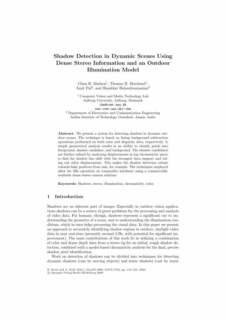
Shadow Detection in Dynamic Scenes 113
Fig. 1. Top: The commercially available Bumblebee XB3 stereo rig from Point GreyResearch, Inc. at approximately 3000 USD. Bottom left: Pseudo-colored disparity imageof an outdoor scene. The dark red patches represent undetected disparities due to pixelsbeing over-exposed or under-exposed, lack of texture, or pixels representing scene pointsthat are not visible in both cameras (occlusion). Bottom right: 3D mesh constructedfrom disparity image and textured with the color information from the RGB image.This scene is a frame with no person.
not move), and that dynamic objects are also present in the scene. In generalthe scene will contain shadows cast by static objects, as well as shadows castby dynamic objects. The techniques presented in this paper are able to detectshadows cast by the dynamic objects, although section 5 demonstrates how thegenerated results can be used to detect the static shadows as well.
The approach presented here has 4 main steps. First we employ a backgroundsubtraction method on the color information (the RGB image). Next we performa similar step on the dense per pixel disparity information, where the backgroundimage in this case represents an acquired depth model of the scene (disparitiesare proportional to metric depth, so there is no reason to spend computationalresources on scaling disparities to metric depth unless metric information isrequired for some other processing step unrelated to the core shadow detection).The third step is to combine the results of the two background subtractionswhich allows us to interpret the nature of each pixel: foreground, background,shadow. This is illustrated in figure 2. The fourth and final step is to evaluatesome chromaticity (normalized color channel information) characteristics of thesegmented shadow pixel population to eliminate those pixels that do not conformto an illumination model which predicts the overall behaviour of regions as theytransition from being exposed to direct sunlight to being in shadow.
Subsequently, the different steps are elaborated in further detail. While wehave an operational C++ real-time implementation of the described approachsome of the results shown in this paper are generated by a similar Matlab
114 C.B. Madsen et al.
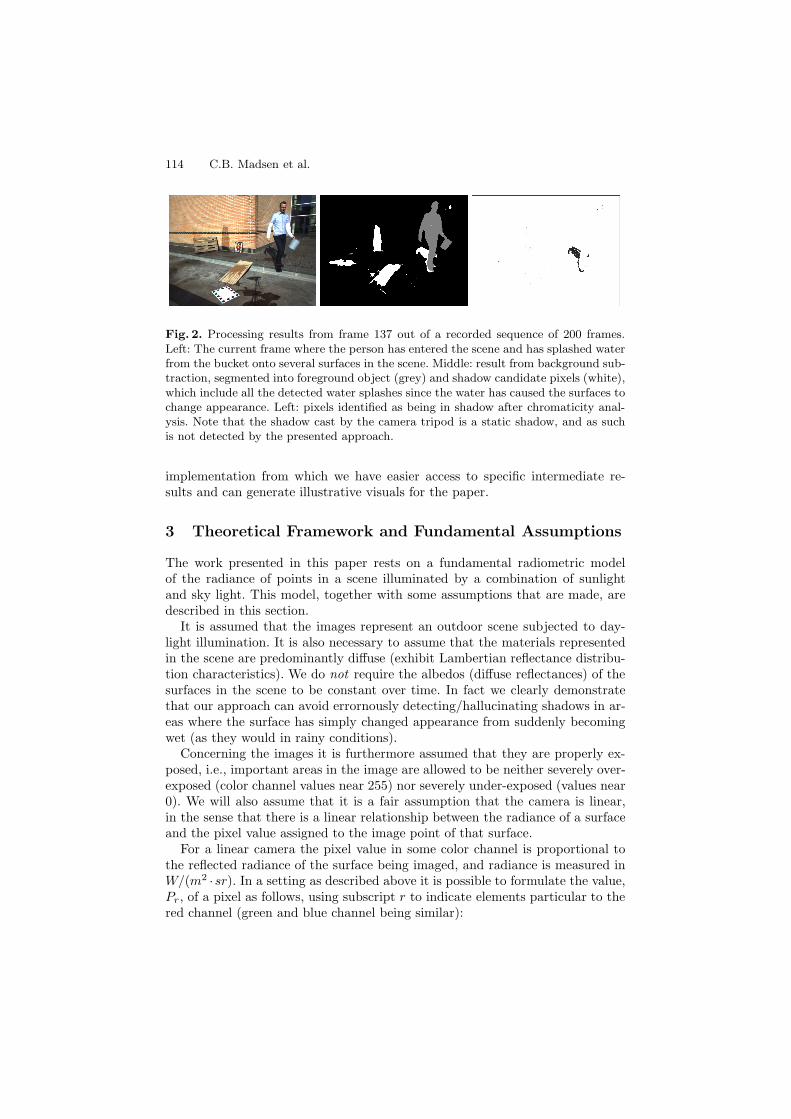
Fig. 2. Processing results from frame 137 out of a recorded sequence of 200 frames.Left: The current frame where the person has entered the scene and has splashed waterfrom the bucket onto several surfaces in the scene. Middle: result from background sub-traction, segmented into foreground object (grey) and shadow candidate pixels (white),which include all the detected water splashes since the water has caused the surfaces tochange appearance. Left: pixels identified as being in shadow after chromaticity anal-ysis. Note that the shadow cast by the camera tripod is a static shadow, and as suchis not detected by the presented approach.
implementation from which we have easier access to specific intermediate re-sults and can generate illustrative visuals for the paper.
3 Theoretical Framework and Fundamental Assumptions
The work presented in this paper rests on a fundamental radiometric modelof the radiance of points in a scene illuminated by a combination of sunlightand sky light. This model, together with some assumptions that are made, aredescribed in this section.
It is assumed that the images represent an outdoor scene subjected to day-light illumination. It is also necessary to assume that the materials representedin the scene are predominantly diffuse (exhibit Lambertian reflectance distribu-tion characteristics). We do not require the albedos (diffuse reflectances) of thesurfaces in the scene to be constant over time. In fact we clearly demonstratethat our approach can avoid errornously detecting/hallucinating shadows in ar-eas where the surface has simply changed appearance from suddenly becomingwet (as they would in rainy conditions).
Concerning the images it is furthermore assumed that they are properly ex-posed, i.e., important areas in the image are allowed to be neither severely over-exposed (color channel values near 255) nor severely under-exposed (values near0). We will also assume that it is a fair assumption that the camera is linear,in the sense that there is a linear relationship between the radiance of a surfaceand the pixel value assigned to the image point of that surface.
For a linear camera the pixel value in some color channel is proportional tothe reflected radiance of the surface being imaged, and radiance is measured inW/(m2 ·sr). In a setting as described above it is possible to formulate the value,Pr, of a pixel as follows, using subscript r to indicate elements particular to thered channel (green and blue channel being similar):
Shadow Detection in Dynamic Scenes 115
Pr = cr · ρr · Er · 1π
(1)
where ρr is the diffuse albedo of the surface point being imaged (ratio of outgoingradiosity to incoming irradiance), and Er is the incoming irradiance in the redchannel. Thus, ρr ·Er is the reflected radiosity. Dividing this by π [sr] yields thereflected radiance of the surface (since the radiosity from a diffuse surface is πtimes the radiance of the surface). Finally, cr is the (typically unknown) scalingfactor translating the measured radiance into pixel value (0 to 255 range for an8 bit camera) for a linear camera. This scaling value depends on the aperture ofthe lens, the shutter speed, the gain, the white-balancing etc. of the camera.
In the kind of outdoor daylight setting we are addressing in this paper thetotal incoming irradiance at a point is a sum of two contributions, Er = Esun
r +E
skyr , again using subscript r for red color channel as example. The amount of
irradiance received from the sun, Esunr , depends on several factors: the radiance
of the sun, how large a fraction of the sun’s disk is visible from the point ininterest (if the sun’s disk is completely occluded the point is in full shadow, alsocalled umbra), and on the angle between the surface normal at the point andthe direction vector to the sun from the point. If the sun’s disk is only partiallyoccluded the point is in the penumbra (soft shadow).
We shall return to this formulation in section 4.3, where we use it to justifyour approach to letting shadow candidate pixels vote for a shadow hue shiftwhich can be used to dismiss pixels that are in fact not in shadow in a particularframe.
4 Methods
As described in section 2 we initially segment each frame into background,foreground, and shadow. This is performed by combining the results from abackground subtraction process on both the color image information and onthe disparity image information. The two background subtraction processes aredescribed below.
4.1 RGB Background Subtraction
We apply the Codebook method [6] since it has been shown to outperform otherbackground subtraction methods [2]. The method contains three steps: modelingthe background, pixel classification and model updating.
Each pixel is modeled as a group of codewords which constitutes the codebookfor this particular pixel. Each codeword is a cylindrical region in RGB-space andfor each new frame each pixel is compared to its codebook. If the current pixelvalue belongs to one of the codewords it is classified as background, otherwiseforeground.
The codebooks are built during training and updated at run-time. The train-ing phase is similar to the pixel classification except that a foreground pixelresults in the construction of a new codeword and a background pixel is used to

116 C.B. Madsen et al.
Fig. 3. Left: Pixels (frame 137) determined by the Codebook method as being differentfrom the trained color background model. Right: Pixels (also frame 137) determinedas being different from the disparity background model.
modify the codeword it belongs to using a standard temporal weighting scheme.The codebooks generated in this way during training will typically fall into threecategories:
Static codebook. For example a pixel representing a road with no shadows orocclusions. Typically only one codeword is used.
Quasi-static codebook. For example a pixel containing the sky, but some-times occluded by vegetation due to wind gusts. During training typicallytwo codewords will be constructed for this codebook, one for the sky andone for the vegetation.
Noisy codebook. One of the above combined with noise in the form of a pedes-trian, car etc. passing by the pixel or noise due to incorrect segmentation.The result will be an often high number of codewords for this codebook.
To handle the noisy codebooks a temporal filter is applied. It is based on theMax Negative Run-Length (MNRL), which is the longest time interval in whicha codeword has not been activated. The filter effectively removes codewords withlittle support during the training phase, such as passing pedestrians.
Normally it is difficult to tune the sensitivity of the Codebook method (andother background subtraction methods for that matter) particularly due to prob-lems with shadows. In this work, however, this is less of a problem since over-segmentation is actually a desired effect. We therefore tune the method to detecteven small changes, and we do not train with shadow regions. This effectivelyresults in a segmentation of the dynamic foreground object including its shadow,see figure 3 for an example.
4.2 Disparity Background Subtraction
We also apply the Codebook method for depth-based background subtraction.Here we only apply one codeword per pixel and its value is not the actual depth

Shadow Detection in Dynamic Scenes 117
Fig. 4. Classification of pixels into foreground (grey), background (black) and shadowcandidates (white)
value, but rather the disparity. The disparity background model is learned asthe Median of a number of training images.
Normally a disparity map contains undefined pixels, due to e.g., noise. Wetherefore smooth the disparity map to obtain more consistent data, and thepixels classified as different from the background also need some clean-up usingstandard morphological operations. We have employed erode followed by dilatewith a radius 5 pixels disk structuring element.
4.3 Shadow Classification
For each pixel in an input image we now have two TRUE/FALSE values withrespect to whether the pixel is different from the RGB background model andwhether it is different from the disparity background model. From this we caninfer the pixel’s type (foreground, background, shadow) as shown in table 1. Infigure 4 a labeling based on table 1 is shown. The rational behind this tablecan be formulated as follows: if the color of a pixel has changed, but there is nochange in disparity, then the pixel has gone from direct light to shadow. If thereis a change in disparity but not in color it can be argued whether to classify it isforeground or background. We have chosen background, since disparity data isless robust than color data, at any rate if there is not change in color it cannotrepresent a shadow.
Table 1. Classification scheme based on results of background subtraction on colorand depth data. It should be noted that only color changes that represent decreasedintensity are valid shadow candidates.
Change in RGB?Yes No
Change Yes Foreground Backgroundin depth? No Shadow Background

118 C.B. Madsen et al.
Fig. 5. Left: population of shadow pixel candidates after logical classification basedon background subtraction on RGB and disparity data. Right: population of shadowpixels after analysis of the permissible shift in the log chromaticity plane.
After this logical classification we are left with a population of dynamic (castby a dynamic object) shadow candidate pixels for each frame. These pixels areshadow candidates only. Predominantly two things can cause pixels to falsely belabeled as shadow pixels: 1) the albedo of the surface changed (for example dueto the surface becoming wet), or 2) imperfections of the disparity data causesthe disparity background subtraction to produce sub-optimal results (see forexample figure 3). All pixels labeled as shadow candidates are shown with theirRGB values in figure 5.
We address the problem of rejecting the non-shadow pixels by returning tothe formulation of the value of a pixel as given in section 3. In log chromaticityspace the pixel values become:
r = log(Pr/Pg)= log(Pr) − log(Pg)= log(cr) − log(cg) + log(ρr) − log(ρg) + log(Er) − log(Eg) (2)
b = log(Pb/Pg)= log(cb) − log(cg) + log(ρb) − log(ρg) + log(Eb) − log(Eg) (3)
The next observation is that the background image depicts the scene free ofdynamic shadows. Thus, if for a given frame a pixel has been classified as ashadow candidate by applying the rules in table 1, we have the same pixel intwo different versions: 1) a version in direct sun light from the background image,where E = Esky + Esun, and 2) a version in shadow from the current frame,where E = Esky (with appropriate indexes for respective color channels). If wesubtract the chromaticity values of these two versions for a given pixel:
rsky − rsun + sky = log
(E
skyr
Esky + sunr
)− log
(E
skyg
Esky + sung
)(4)

Shadow Detection in Dynamic Scenes 119
Fig. 6. Histogram over chromaticity displacement vector orientations, measured in therange from -180 degrees to +180 degrees. In this case the histogram has two peaks, oneat around -45 degrees, corresponding to the darkening of the wooden plate as a resultof a water splash, and one at around 90 degrees, corresponding to the actual blue shiftof the shadow.
bsky − bsun + sky = log
⎛⎝ E
skyb
Esky + sunb
⎞⎠− log
(E
skyg
Esky + sung
)(5)
Looking at eqs. 4 and 5 we see that by subtracting the log chromaticity coordi-nates of the two different versions of a pixel we get a 2D vector in log chromaticityspace which is independent of camera properties (the cr/g/b scaling constants),and independent of the material properties (the ρr/g/b albedos). The only thingsthat influence these log chromaticity displacement/hue shift vectors are the ir-radiances. Furthermore the depth of the shadow (determined by the amount ofsun disk occlusion and the angle between the surface normal and the directionvector to the sun) only influences the length of this displacement vector, not thedirection.
With these observations we compute the orientations of all these displacementvectors (one for each of the shadow pixel candidates) and form a histogram ofthe orientations in the range from -180 to +180 degrees, see figure 6. The numberof bins in the histogram is set to the number of shadow candidate pixels dividedby 50 to ensure a reasonable number of candidates in each orientation bin. Theminimum number of bins is 10, though, to handle the case of very few detectedshadow candidates.
Since the spectrum of light from the sky is dominated by wavelengths in theblue channel pixels that go from direct sun light to shadow conditions will un-dergo a blue shift, which in terms of the histogram in figure 6 corresponds todisplacement orientation near +90 degrees (in rb chromaticity space blue chro-maticity is upwards). We therefore search the histogram to find a local maximumnear 90 degrees. The chosen peak corresponds to the chromaticity shift pixelsundergo when they transition from shadow to direct light. All pixels whose dis-placement vectors are not close to (in our system within 20 degrees of) this

120 C.B. Madsen et al.
Fig. 7. Left: The detected log chromaticity blue shift direction (in degrees) as a functionof frame number. Right: The number of verified shadow pixels in the scene as a functionof frame number. When there are too few shadow pixels (less than around 500) thedirection cannot be detected robustly.
“most voted for direction” are classified as not shadow pixels and are removedfrom the shadow pixel population. The remaining pixels all exhibit the samebehaviour in log chromaticity space and are thus all consistent with the illumi-nation model. In figure 5 it can be seen how this chromaticity analysis removeswrongly detected shadow pixels, especially those corresponding to all the watersplashes (which have changed the albedo of the surfaces).
5 Results and Discussion
This section will address a set of relevant issues in relation to the presentedtechniques. We take a closer look at the estimated blue shift direction over atime sequence, we address overlapping shadows, then discuss long time sequencesand demonstrate how this work can be operated in a mode with no backgroundmodel, and finally we discuss some of the assumptions made in this work.
5.1 Blue Shift Direction
The proposed automatic approach to finding the blue shift direction is remark-ably robust. Figure 7 plots the chosen direction for the 200 frame sequence usedin the above description. The same figure also shows the development in thenumber of verified shadow pixels per frame through the sequence, and it is es-sentially seen that the blue shift direction is found robustly whenever there is asufficient number of shadow pixels available in the scene.
5.2 No Background Model Mode
Our approach as described this far is based on background subtraction in bothcolor and disparity data. As a result shadows that are static, i.e., part of thebackground image model, do not get detected. Another drawback of using back-ground subtraction is that for very long image sequences (days, weeks, months

Shadow Detection in Dynamic Scenes 121
Fig. 8. In partly overcast, windy conditions illumination changes can be drastic. Thesetwo frames are 15 frames apart, corresponding to a time difference of 1.5 second. Onaverage the latter image is 50% brighter than the former.
...) it can be difficult to maintain the background model due to highly varying il-lumination, precipitation, seasonal changes, etc. Figure 8 shows how drasticallythe illumination can change from one to second to the next, making classicalbackground subtraction very difficult, if not impossible.
To address this problem we demonstrate that image differencing can be em-ployed instead of the background subtraction step. The sequences used in thispaper are recorded with 10 frames per second. If we perform image differencingon color and disparity images by subtracting frame T (current frame) and frameT − ΔT (some frames old), and perform everything else similar to what hasbeen described in the paper, we can detect dynamic shadows with no training ofbackground models at all. Δ can be adjusted to find a compromise between be-ing very robust towards rapidly changing illumination (small ΔT ) and detectingall of the shadow area (large ΔT ). If ΔT is small compared to the movementsof shadows in the scene the shadows in the two frames will overlap, and onlypart of the shadow will be detected (the part which is in shadow in frame T butnot in frame T − ΔT ). In this paper we have used a ΔT of 0.5 second, i.e., weperform image differencing with a 5 frame delay. Figure 9 shows some detectionresults from a sequence acquired under highly varying illumination conditions.
5.3 Detecting All Shadows
By definition our approach only detects the dynamic shadows, regardless ofusing the background model or the image differencing mode. To address thisproblem the technique presented here can be combined with an implementationof the technique described in [8]. That method, as described in section 1, requiresmanual initialization (ratios of sky to sun-plus-sky irradiances for each colorchannel).
A by-product of the shadow detection technique described here is that it canprovide those ratios. These ratios are straight forward to compute, as they arejust the per color channel averages of the ratios of detected dynamic shadow

122 C.B. Madsen et al.
Fig. 9. Dynamic shadow detection based on image differencing (frames 180, 520, and1741).
pixel values to their non-shadow pixel values. In the case of using the imagedifferencing mode: if image differencing between frame T and frame T − ΔTresults in a pixel being classified as dynamic shadow, then compute the percolor channel ratio of pixel value in frame T to the pixel value in frame T −ΔT .For a diffuse surface this ratio equals the sky to sun plus sky irradiance ratio,see section 3. The average of these ratios for all dynamic shadow pixels in agiven frame provides the initialization information for the graph cuts techniquefrom [8].
Figure 10 shows the results from using the dynamically detected shadows toboot-strap the graph cuts based shadow segmentation and removal technique,which is capable of handling soft shadows.
5.4 Assumptions Revisited
As described in section 3 this work rests on a number of assumption that areworth discussing. The assumption of the camera being static makes it possibleto employ background models or to use simple image differencing as shownabove. It would be possible to extend this work to a camera placed on a pan-tilt unit. Omni-directional depth background models are employed in e.g., [1].If the mounted on a pan-tilt unit a spherical representation of the color anddepth background model could be composed by scanning in all directions. Ifusing the image differencing mode optical flow techniques could be employedto compute the overlap between the current frame and the delayed frame usedfor subtraction. This way the dynamic shadows in the overlap region could bedetected and the information from the shadow pixels could then be used fordetecting all shadows in the current frame as described in section 5.3.
Shadow Detection in Dynamic Scenes 123
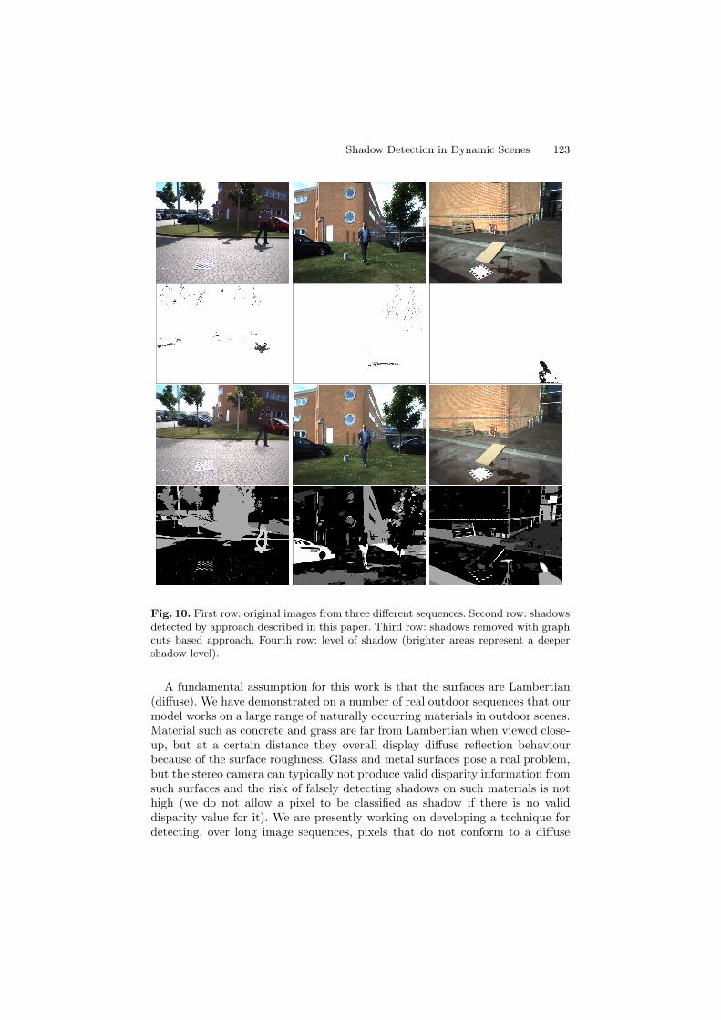
Fig. 10. First row: original images from three different sequences. Second row: shadowsdetected by approach described in this paper. Third row: shadows removed with graphcuts based approach. Fourth row: level of shadow (brighter areas represent a deepershadow level).
A fundamental assumption for this work is that the surfaces are Lambertian(diffuse). We have demonstrated on a number of real outdoor sequences that ourmodel works on a large range of naturally occurring materials in outdoor scenes.Material such as concrete and grass are far from Lambertian when viewed close-up, but at a certain distance they overall display diffuse reflection behaviourbecause of the surface roughness. Glass and metal surfaces pose a real problem,but the stereo camera can typically not produce valid disparity information fromsuch surfaces and the risk of falsely detecting shadows on such materials is nothigh (we do not allow a pixel to be classified as shadow if there is no validdisparity value for it). We are presently working on developing a technique fordetecting, over long image sequences, pixels that do not conform to a diffuse

124 C.B. Madsen et al.
reflection assumption (i.e., do not over the entire sequence consistently vote forthe same illumination model as the majority of the pixels in the scene).
Finally, the theoretical framework is based on an assumption of the camerahaving a linear response curve, and that the color channels are independent.This is typically only true for very high quality cameras, and certainly the cam-eras in the Bumblebee stereo rig are not designed for color vision applications.Regardless, we have demonstrated that the model works quite well even withcameras of such low quality.
6 Conclusion
We have presented a technique for detecting shadows in dynamic scenes. Themain contributions lie in the combination of color and disparity data analysis,and in the use of qualitative chromaticity plane descriptors for ruling out falsepositives in the shadow pixel populations. A powerful feature of the proposedapproach is its ability to handle albedo changes in the scene, e.g., its robustnesstowards falsely labeling pixels as shadow in situations where surfaces in the scenehave become wet. Another promising feature of the work is that the techniquesemployed allow for 3Hz operation on commodity hardware using a commerciallyavailable dense stereo camera solution.
We conjecture that by enabling vision systems to estimate information aboutthe illumination conditions in the scene the vision systems can be made morerobust. In this paper we have demonstrated that it is possible to estimate pow-erful information concerning the scene illumination in terms of the illuminantdirection which can be utilized to verify dynamic shadows and to detect staticones, as well.
Future work will include combining this work with static shadow detection,working with temporal analysis of the detected shadows and illumination in-formation, and using this illumination estimation for realistic augmentation ofsynthetic objects into the scenes.
Acknowledgments
This research is funded by the CoSPE (26-04-0171) and the BigBrother (274-07-0264) projects under the Danish Research Agency. This support is gratefullyacknowledged.
References
1. Bartczak, B., Schiller, I., Beder, C., Koch, R.: Integration of a time-of-flight camerainto a mixed reality system for handling dynamic scenes, moving viewpoints andocclusions in real-time. In: Proceedings of the 3DPVT Workshop, Atlanta, GA,USA (June 2008)
Shadow Detection in Dynamic Scenes 125
2. Chalidabhongse, T.H., Kim, K., Harwood, D., Davis, L.: A Perturbation Methodfor Evaluating Background Subtraction Algorithms. In: Joint IEEE InternationalWorkshop on Visual Surveillance and Performance Evaluation of Tracking andSurveillance, Nice, France, October 11-12 (2003)
3. Finlayson, G.D., Hordley, S.D., Drew, M.S.: Removing shadows from images.In: Heyden, A., Sparr, G., Nielsen, M., Johansen, P. (eds.) ECCV 2002. LNCS,vol. 2353, pp. 823–836. Springer, Heidelberg (2002)
4. Hu, J.-S., Su, T.-M.: Robust Background Subtraction with Shadow And High-light Removal for Indoor Surveillance. Journal on Advanced in Signal Process-ing 2007(1), 108–132 (2007)
5. Huerta, I., Holte, M.B., Moeslund, T.B., Gonzalez, J.: Detection and removal ofchromatic moving shadows in surveillance scenarios. In: Proceedings: IEEE ICCV2009, Kyoto, Japan (September 2009)
6. Kim, K., Chalidabhongse, T.H., Harwood, D., Davis, L.: Real-time Foreground-Background Segmentation using Codebook Model. Real-time Imaging 11(3),167–256 (2005)
7. Moeslund, T.B., Hilton, A., Kruger, V.: A Survey of Advances in Vision-BasedHuman Motion Capture and Analysis. Journal of Computer Vision and ImageUnderstanding 104(2-3) (2006)
8. Nielsen, M., Madsen, C.B.: Graph cut based segmentation of soft shadows forseemless removal and augmentation. In: Proceedings: Scandinavian Conference onImage Analysis, Aalborg, Denmark, June 2007, pp. 918–927 (2007)
9. Nielsen, M., Madsen, C.B.: Segmentation of soft shadows based on a daylight- andpenumbra model. In: Gagalowicz, A., Philips, W. (eds.) MIRAGE 2007. LNCS,vol. 4418, pp. 341–352. Springer, Heidelberg (2007)
10. Prati, A., Mikic, I., Trivedi, M.M., Cucchiara, R.: Detecting Moving Shadows:Algorithms and Evaluation. IEEE Transactions on Pattern Analysis and MachineIntelligence 25, 918–923 (2003)
11. Salvador, E., Cavalarro, A., Ebrahimi, T.: Shadow identification and classifica-tion using invariant color models. Computer Vision and Image Understanding 95,238–259 (2004)
12. Point Grey Research: Bumblebee,http://www.ptgrey.com/products/bumblebee/index.html