Aalb orgprojekter.aau.dk/projekter/files/61055052/1023995105.pdf · Aalb org ersitet Univ Institut...
138
Transcript of Aalb orgprojekter.aau.dk/projekter/files/61055052/1023995105.pdf · Aalb org ersitet Univ Institut...

� Aalborg UniversitetInstitut for Elektroniske SystemerAfdeling for DatalogiFredrik Bajers Vej 7E9220 Aalborg Øhttp://www. s.au .dk� Aalborg UniversitetAfdeling for Computer Vision og Medi-eteknologiNiels Jernes vej 149220 Aalborg Øhttp://www. vmt.au .dkInteraktiv 3D ModelleringKunstnerisk formgivning i virtuelle miljøerProjekt periode: 4. februar - 14. juni 2002Semester: Dat6 Synposis:Projekt gruppe:N4-307bDeltagere:Morten Flyger ��yger� s.au .dkJim Kynde Meyer �meyer� s.au .dkKenneth Pedersen �kepe� s.au .dkVejledere:Claus Brøndgaard Madsen � bm� vmt.au .dkPeter Bøgh Andersen �pba� s.au .dkAntal kopier: 9Antal sider: 128
Denne rapport dokumenterer et projekt somomhandler kunstnerisk formgivning i virtuellemiljøer. Vi har udført en analyse af tegn-ingsprin ipper, hvordan kunstnere arbejder iden fysiske verden og ved at læse i relateretlitteratur. Kunstnerne vi valgte at observerevar en keramiker og en glaspuster. Ydermerevalgte vi at observere hvordan en 3D-kunstnermodellerede nogle af objekterne, fra de fysiskekunstnere, i Maya. Vi fandt ud af, at vi ikkekunne �nde et unikt modelleringsparadigme,som kunne dække de ønskede egenskaber i etsystem til kunstnerisk formgivning. Dette �kos til at designe en platform som kunne inklud-ere �ere paradigmer, som moduler og plug-ins.Endelig valgte vi at inkludere tredje parts soft-ware til at håndtere adgang til hardware og dengeometriske matematik. På grund af den be-grænsede tid vi havde til rådighed, valgte vikun at implementere en del af det designede sys-tem. Vi valgte et modelleringsparadigme kaldetSurfa e Drawing, da vi fandt frem til at dettekunne fungere som Proof-of-Con ept på kunst-nerisk formgivning i vores system.Copyright © 2002 Projekt Gruppe N4-307b. Alle rettigheder forbeholdes.


� Aalborg UniversityInstitute of Ele troni SystemsDepartment of Computer S ien eFredrik Bajers Vej 7E9220 Aalborg Øhttp://www. s.au .dk� Aalborg UniversityDepartment of Computer Vision andMedia Te hnologyNiels Jernes vej 149220 Aalborg Øhttp://www. vmt.au .dkIntera tive 3D ModelingArtisti Shape Design in Immersive Virtual EnvironmentsProje t period: February 4. - June 14. 2002Semester: Dat6 Abstra t:Proje t group:N4-307bParti ipants:Morten Flyger ��yger� s.au .dkJim Kynde Meyer �meyer� s.au .dkKenneth Pedersen �kepe� s.au .dkSupervisors:Claus Brøndgaard Madsen � bm� vmt.au .dkPeter Bøgh Andersen �pba� s.au .dkNumber of opies: 9Pages: 128
This report do uments a proje t that on ernsartisti shape design in virtual environments.We performed an analysis of drawing prin i-ples, how artist model in the real world, and �-nally by studying related literature. The artistswe hose to study, were a erami artist anda glassblower. Furthermore, we studied a 3Dgraphi artist model some of the obje ts, whi hwe saw modeled by the real world artists, inMaya. We realized that we ould not identifyone unique paradigm, whi h ould over the fea-tures needed for artisti shape design. Realizingthis, we designed a platform, that has the abil-ity to in lude several paradigms, as modules andplug-ins. Furthermore, we in luded third partysoftware to handle hardware a ess and geomet-ri mathemati s. Due to the limited time pe-riod at hand, we de ided to implement only apart of the designed system. We hose a model-ing paradigm alled Surfa e Drawing, sin e wede ided that it would fun tion as our Proof-of-Con ept of artisti shape design with our sys-tem.Copyright © 2002 Proje t Group N4-307b. All Rights Reserved.


Prefa eThis report is written by proje t group N4-307b on the 8th. semester at theDepartment of Computer S ien e at Aalborg University.It is primarily written for the members of the proje t group, the supervisorsand the ensor. Se ondarily, it an be of some use for people with interestin modeling in the area of Virtual Reality (VR) (See Appendix B) and thework pro ess of erami artists, glassblowers and 3D modeling experts. Allthe implemented parts of the proje t (sour e and ompiled �les) and thisreport an be found at:http://www. s.au .dk/�flyger/P8/Throughout the report the proje t group's itations are indi ated with [ ℄ ontaining a label, that uniquely identi�es a itation, whi h is des ribed inthe bibliography. The sour e ode is written in monospa e and �gures arenumerated onse utively. Everywhere in the report, where he or his is used,the proje t group means he/she or his/hers. Everywhere we or our is used itrefers to the proje t group and its a tivities.We would like to thank Steven S hkolne at Calte h University for being veryhelpful and for providing us with sour e ode regarding Surfa e Drawing.Furthermore, we would like to thank Peter Skotte for produ ing 3D obje ts inMaya as 3D modeling expert, and �nally Lange Handi raft and Lene HøjlundGlassblowing for giving us the ne essary knowledge of their workpro essesand their use of tools.Aalborg University, June 14th 2002.Morten Flyger Jim Kynde Meyer Kenneth Pedersen


Contents1 Introdu tion 1I Analysis 72 Drawing Prin iples 92.1 The Drawing Pro ess . . . . . . . . . . . . . . . . . . . . . . . 92.2 Analyti al Drawing and Proportion . . . . . . . . . . . . . . . 102.3 Building on Geometry . . . . . . . . . . . . . . . . . . . . . . 113 Case Studies 153.1 Overview . . . . . . . . . . . . . . . . . . . . . . . . . . . . . . 153.2 Sele ted Cases . . . . . . . . . . . . . . . . . . . . . . . . . . . 163.2.1 Lange Handi raft . . . . . . . . . . . . . . . . . . . . . 173.2.2 Lene Højlund Glassblowing . . . . . . . . . . . . . . . 213.2.3 3D Graphi Artist . . . . . . . . . . . . . . . . . . . . 233.3 Dis ussion of Con epts . . . . . . . . . . . . . . . . . . . . . . 293.3.1 The Revolve Pro ess . . . . . . . . . . . . . . . . . . . 323.3.2 The Cutting and Carving Pro esses . . . . . . . . . . . 333.3.3 The Deformation Pro ess . . . . . . . . . . . . . . . . . 353.3.4 Summary of Con epts . . . . . . . . . . . . . . . . . . 363.4 Further Observations . . . . . . . . . . . . . . . . . . . . . . . 373.4.1 Di�eren es in Work Pro esses . . . . . . . . . . . . . . 37

viii CONTENTS3.4.2 Immersive Environments . . . . . . . . . . . . . . . . . 383.4.3 Intera tion Loop . . . . . . . . . . . . . . . . . . . . . 394 Guidelines for Paradigm Sele tion 414.1 Fun tionality . . . . . . . . . . . . . . . . . . . . . . . . . . . 414.2 Intera tion . . . . . . . . . . . . . . . . . . . . . . . . . . . . . 424.3 Platform . . . . . . . . . . . . . . . . . . . . . . . . . . . . . . 435 Related Work 455.1 Constru tion Paradigms . . . . . . . . . . . . . . . . . . . . . 485.2 Deformation Paradigms . . . . . . . . . . . . . . . . . . . . . 515.3 Hybrid Paradigms . . . . . . . . . . . . . . . . . . . . . . . . . 556 Analysis Summary 61II Design & Implementation 637 Design 657.1 System Ar hite ture . . . . . . . . . . . . . . . . . . . . . . . 657.2 Component Spe i� ations . . . . . . . . . . . . . . . . . . . . 687.2.1 The Module Layer . . . . . . . . . . . . . . . . . . . . 687.2.2 The Plug-in Layer . . . . . . . . . . . . . . . . . . . . 707.2.3 The ASD API . . . . . . . . . . . . . . . . . . . . . . . 737.2.4 VR Juggler . . . . . . . . . . . . . . . . . . . . . . . . 757.2.5 openNURBS . . . . . . . . . . . . . . . . . . . . . . . . 777.3 Intera tion Considerations . . . . . . . . . . . . . . . . . . . . 787.3.1 Intera tion Levels . . . . . . . . . . . . . . . . . . . . . 797.3.2 Sele ting the Right Kind of Tools . . . . . . . . . . . . 807.4 An Artisti Modeling Paradigm on the ASD Platform . . . . . 817.4.1 Design of Surfa e Drawing on the ASD Platform . . . . 838 Implementation 87

CONTENTS ix8.1 Classes . . . . . . . . . . . . . . . . . . . . . . . . . . . . . . . 908.2 Implementation Issues . . . . . . . . . . . . . . . . . . . . . . 938.3 The Appli ation . . . . . . . . . . . . . . . . . . . . . . . . . . 949 Design & Implementation Summary 99III Future Work & Con lusion 10110 Future Work 10311 Con lusion 105Bibliography 109IV Appendi es 113A VR Juggler 115A.1 Overview . . . . . . . . . . . . . . . . . . . . . . . . . . . . . . 115A.2 VR Juggler Helper Classes . . . . . . . . . . . . . . . . . . . . 118A.3 The Control Loop . . . . . . . . . . . . . . . . . . . . . . . . . 120B Virtual Reality 125B.1 Overview . . . . . . . . . . . . . . . . . . . . . . . . . . . . . . 125B.2 Human-Computer Intera tion . . . . . . . . . . . . . . . . . . 125


1 Introduction
Computer graphi s and geometri modeling is a huge resear h area withinthe omputer s ien e ommunity, and as su h great progress has been made.Computer systems aid in the pro ess of shape design in a number of indus-tries, in luding the traditional engineering dis iplines su h as automobile andaeroplane design, and in re ent years also in the entertainment industries andfor industrial design.As a result, the state of the art in omputerized 3D modeling systems an beused for reating a wide olle tion of omplex surfa es, when in the hands ofexpert users with extensive experien e. Although these systems, that are of-ten based on splines [B�86℄, have proven their worth, they still la k propertiessu h as reative freedom and artisti expression. One of the major problemswith spline-based systems, is the fa t that users are for ed to think in termsof the underlying mathemati al stru ture at the beginning of the modelingpro ess, in order to represent their shape in an a�e tive way. Investigatingalternatives for a shape during the modeling pro ess, will require the user to reate dramati hanges in the pla ement of the spline-based pat hes, and inextreme ases, starting from s rat h seems to be the best alternative [SS99℄.Seeking reative freedom, artists often turn away from the omplex 3D mod-eling appli ations, and instead prefer simple tools su h as a pie e of paperand a pen il as well as physi al media like lay and glass for artisti expres-sion. Even though the pen il is a very simple tool, it is an extraordinarilye�e tive way of expressing intri ate shapes dire tly, sin e it provides a lose onne tion between an artist's per eption and a tion, and the forms the pen- il produ es [SS99℄. The la k of intuitiveness and reative freedom in thetraditional omputerized modeling tools results in the artists using them forspe i� ation rather than reation in the on eptual phase. Our intention

2 1. Introdu tionwith this report is to do ument a series of studies, that will lose the gapbetween on eptualization and spe i� ation using omputerized 3D model-ing appli ations, in order to provide artists with new ways of expression and reative freedom.Physical Reality:
Terminology:
Virtual Reality:
Perception:
Artistic
Shape
Design
Conceptualization
"Thinking"1
3
4
2
Realization
"Doing"
Visual Tactile
Modeling Paradigm: Construction Deformation
Sketching using
paper and pencil
(2D)
Sketching in
immersive
environments
(3D)
Simulation of
physical modeling
Physical
modeling
Figure 1.1: A view of artisti shape design, that forms the problem ontext ofthis reportFigure 1.1 illustrates the problem ontext for our studies, namely �Artisti Shape Design� (ASD). Sket hing using paper and pen il, and physi al mod-eling with materials su h as lay form the basis for the tools used by artistsin the real world, whi h we will refer to as physi al reality. When movingtowards omputerized modeling systems, we �nd two somewhat ompetingapproa hes, with rather di�erent ideas and ways to think about modeling.One, sket hing in immersive environments, seeks to expand the traditionalpaper and pen il a tivity, whi h is inherently two-dimensional, to be a three-dimensional tool, that dire tly links the reation of shapes in their full dimen-sion with the expressive power of the pen il. The se ond approa h, simulationof physi al modeling, is based on the idea of re reating the feeling of modelingin the physi al world, utilizing mathemati al models for material propertiessu h as elasti ity and plasti ity. We will refer to these two approa hes as on-

3stru tion versus deformation, in the sense that they represent two di�erent ategories of modeling paradigms.An interesting observation is that one of the major short omings in tradi-tional modeling appli ations, is their weak usage of per eption, that is a verypowerful me hanism for learning and understanding. The use of per eptionis mu h more visible in the tools hosen by artists, and a ru ial part of theirdesign pro ess. To understand this, we need to understand what per ep-tion is, and how it a�e ts the artist. A ording to [Di 02℄, the de�nition ofper eption is as follows:per eption n.1. The pro ess, a t, or fa ulty of per eiving.2. The e�e t or produ t of per eiving.3. Psy hology.(a) Re ognition and interpretation of sensory stimuli based hie�y on memory.(b) The neurologi al pro esses by whi h su h re ognitionand interpretation are e�e ted.4. (a) Insight, intuition, or knowledge gained by per eiving.(b) The apa ity for su h insight.The traditional modeling appli ations fail to utilize these me hanisms, pos-sibly be ause of their heritage from earlier systems, that fo used mainly onmathemati al representation rather than intera tion. With regards to theuse of sensory stimuli, the most evident short omings in lude the use of two-dimensional visualization and intera tion devi es with worlds and obje tsthat are inherently three-dimensional. Se ondly, users an not re ognizeshapes for what they are, but are for ed to think in terms of ontrol points,pat hes and polygons, that however lever they may be in the mathemati alsense, are ounter-intuitive and di� ult to understand [SPSa℄.With tools su h as the paper and pen il, artists an think dire tly in termsof the shape they are trying to express, and their movements of the pen il isdire tly linked with their per eption of the shape. In this ase their primarymeans of per eption is visual information. Physi al modeling uses ta tileresponse as an important means of per eption, allowing the artist to under-stand the shape of the obje t he is working on. Although visual informationis also useful, the feeling of the material is essential, sin e deformation isdi� ult to ontrol without ta tile response.

4 1. Introdu tionAs powerful and intuitive sket hing and physi al modeling may be, theystill leave things to desire for the artist. This leads us to investigate howthe �exibility and advantages of digital representation and modeling, an be ombined with the intuitive and powerful sket hing and physi al modeling,without introdu ing the short omings of the traditional modeling appli a-tions. We believe, that an appli ation that exhibits these properties anbe useful in many ontexts, in luding the role of a support tool for artists,but also as the primary tool for the reation of virtual art, that reates newpossibilities, su h as viewing and ollaboration of art a ross physi al bound-aries. Another use of su h an appli ation for artisti shape design, is forentertainment purposes mu h like people enjoy sket hing, painting, and us-ing physi al media like lay. Finally, this kind of appli ation has potentialas a tool for early on eptualization in the entertainment industries, eg. forgame- and hara ter design and movies, as well as in the early phases ofindustrial design, for rapid evaluation and reation of ideas and shapes.One of the reasons for moving from physi al reality towards virtual realityand immersive environments is the dimensional gap between the paper andpen il, and physi al modeling, as illustrated by arrow number 1 in Figure1.1. Artists an qui kly sket h new ideas, but the paper and pen il somehowlimits true exploration of three-dimensional form, as it is restri ted to twodimensions. Physi al modeling is inherently three-dimensional, but the mod-eling is governed by the laws of physi s, that restri t the reative freedom ofthe artist, setting the boundaries for what is, and is not, possible to do.As we an ontrol how we model the laws of physi s in an immersive envi-ronment, we an literally suspend things like gravity, and even reate newobje ts from thin air. It is our belief, that this ontrol an provide artistswith previously unseen degrees of reative freedom and artisti expression.However, this vision introdu es several hallenges, te hni al as well as non-te hni al, before this goal is rea hed. Consider the arrow marked as number2 in Figure 1.1, whi h represents the hallenges of expanding the traditionaltwo-dimensional sket hing to three dimensions. In this ase, questions like�How do we in lude a third dimension without negating the bene�ts of sket h-ing in two dimensions?�, and �Is there an additional need of providing theartist with tools, that help and guide the artist in using the extra degree offreedom?�, ome to mind.Moving physi al modeling from physi al reality to virtual reality, as illus-trated by arrow number 3 in Figure 1.1, also poses a number of hallenges.Ideally an artist should be unable to di�erentiate between the simulationrunning on a omputer system, and modeling in physi al reality, for him to

5work in the same intuitive way with digital materials. This gap is no longera on eptual and dimensional one, as in the ase of sket hing, but insteada matter of orre t representation and behavior of the materials modeledwith the system. We believe, that the greatest hallenges in this ontext willbe to devise mathemati al models that are suitable for intera tive real timepurposes, ombined with the engineering of advan ed hardware te hnologiesfor providing hapti feedba k, eg. the feeling of tou hing and deforming anobje t, sin e this is an important means of per eption in physi al modeling.Lastly, arrow number 4 in Figure 1.1 denotes a link between the onstru tionand deformation paradigms, in the sense that expanding artisti shape de-sign to immersive environments may reveal ompletely new hybrid modelingparadigms, that seek to ombine the best of both paradigms.As stated earlier in this hapter, extending artisti shape design to immersivevirtual environments sets forward a number of te hni al hallenges within thearea of omputer s ien e and hardware engineering. As we see it, the pri-mary non-te hni al hallenges in lude gathering information about the workpro ess of artists as they work in physi al reality, be it by sket hing or usingphysi al media su h as lay. A thorough understanding of these pro esseswill be ru ial in the design of intera tive modeling appli ations for artisti shape design, in order to provide the artists with the intuitiveness, reativefreedom and artisti expression they have ome to expe t from their tools.We will a quire this knowledge by a study of drawing prin iples ombinedwith a series of ase studies, in whi h we will observe artists from di�erentartisti trades and 3D graphi designers as they work with shape design.This learning pro ess, whi h is illustrated in Figure 1.2 on the next page,forms the basis for the analysis do umented in this report.The remainder of the report is stru tured as follows. Chapter 2, DrawingPrin iples, do uments the knowledge gained in the study of these prin iples,that fun tion as a knowledge base that is useful for assessing already ex-isting te hni al solutions, and for setting forth a number of guidelines thatintera tive modeling appli ations for artisti shape design should adhere to.Case Studies, in Chapter 3, des ribes the ase studies we performed, in orderto identify how spe i� groups of people use their hands for reative pur-poses, and what tools they utilize to a hieve ertain tasks. Guidelines forParadigm Sele tion in Chapter 4 sets forth a number of guidelines for hoos-ing modeling paradigms, that are suitable for artisti shape design. Chapter5, Related Work, presents an overview of resear h and literature that is re-lated to the ontext of our proje t, and dis usses ea h of these so alledmodeling paradigms based on the knowledge gained in the previous parts ofthe analysis. Chapter 6 summarizes upon the Analysis part, and presents

6 1. Introdu tionProblem Context
Case Studies
Drawing
Principles
emphasises
which is an
integral part of
that may be used to
improve the design
process of
in order to provide
artists with new ways
of expression and
creative freedom
Artistic
Shape
Design
Computer
Aided
Graphics
Design
Physical Modeling
and
Sketching
Visual thinking
Natural interaction
Creative freedom
Flow of thought
Figure 1.2: The problem de�nition for artisti shape design, that forms thefoundation for the analysis in this reportfurther elaborations of the topi s dis ussed in that part.Design in Chapter 7 des ribes the design of a platform for an intera tivemodeling appli ation for artisti shape design, that takes into onsiderationthe lessons learned from the ase studies and our investigation of drawingprin iples, as well as the guidelines for su h an appli ation, whi h we presentin this report. The hapter also des ribes the hoi e of a modeling paradigmfor artisti shape design, that runs on the ASD platform, whi h we presentlater in this report. Implementation in Chapter 8 do uments the implemen-tation performed during this semester, and dis usses the results a hieved andthe problems en ountered. Also, this hapter presents the apabilities of theappli ation we implemented, and the hardware setup it utilizes. Chapter 9summarize upon the Design & Implementation part, and elaborates uponthe topi s dis ussed in that part.The �nal part, starting with Future Work in Chapter 10, provides an overviewof the future work we identi�ed, followed by Con lusion in Chapter 11, that on ludes on the resear h results in this report.
Part
1This part contains the analysis performed. As mentioned in the
Introduction, we found it relevant to study drawing principles
to learn how drawing and sketching was carried out in 2D. Fur-
thermore, we did some fieldwork to study how real world ar-
tists model. Here we studied both artists working with ceram-
ics and glass, but also a professional 3D computer modeller.
These studies are discussed and compared before we set some
guidelines for how the remaining part of the project should
elapse. Finally, we studied related work to identify existing
paradigms which fulfill the guidelines and our intentions with
this project.
Analysis


2 Drawing Principles
To learn about the prin iples of drawing, we studied literature in that area.The following is a des ription of some of the prin iples we learned about in[CJ98℄. This book starts with the introdu tion:�Drawing is the pro ess or te hnique of representing something -an obje t, a s ene, or an idea - by making lines on a surfa e.�We wish to extend this de�nition to drawing in 3D, and in this ontext we�nd it relevant to look loser at the three following topi s from this book.2.1 The Drawing Pro essEven with ele troni medias and augmented traditional drawing methods,drawing remains a ognitive pro ess that involves per eptive seeing and visualthinking. All drawing is an intera tive pro ess of seeing, imagining andrepresenting images, as illustrated on Figure 2.1 on the following page.Seeing is the use of vision. This sense makes drawing possible, and drawingsupports seeing. Imagining is the pro essing of the data re eived by the eye.The mind sear hes for a stru ture and meaning. The minds eye reates theimages we see, whi h are the images we are trying to draw. The use of visualthought raises drawing beyond a manual skill. Representing is the makingof marks, for instan e, on a surfa e to graphi ally represent the image in theminds eye. This graphi ally representation then speaks to the eye.

10 2. Drawing Prin iplesSeeing
Representing
Imagining
Figure 2.1: The intera tive pro ess of seeing, imagining and representing images2.2 Analyti al Drawing and ProportionUnlike ontour drawing, where ea h area of the drawing is �nished beforemoving on, analyti al drawing pro eeds from the whole drawing to the sub-ordinate parts and �nally the details. To work with analyti al drawing isoften preferred in preferen e to ontour drawing, be ause analyti al drawingtypi ally results in a better stru ture and ontrol of proportions, sin e thewhole drawing is taken in onsideration already in the �rst strokes. The �rststep of analyti al drawing is lightly drawing of lines to establish a transpar-ent volumetri framework for a form. This framework helps in drawing thethree-dimensional form. Some additional lines an support in �nding for in-stan e the enter of the drawing, and the framework an be used for drawingthe surfa e lines. Figure 2.2 on the next page illustrates a bottle drawn froma framework.Regulating lines is used for lo ating points in the framework. Approximatelines help the eye seek the orre t lines, whi h an then be orre ted. Thefo us on volume as well as surfa e helps avoiding �at obje ts, whi h is typi alwhen the fo us is only on the surfa e. Before a line is drawn, the endpointsare marked with dots, and the line is pra ti ed by moving the hand along theintended line. Furthermore the pen il is always pulled, never pushed. Thismeans that a right-handed always draws lines from left to right and from topto bottom.Proportion is explained in [CJ98℄ as follows:�Proportion is the omparative, proper, or harmonious relationof one part to another or to the whole with respe t to magni-tude, quantity, or degree. Proportional relations are a matter ofratios, and ratio is the relationship between any two parts of a

2.3. Building on Geometry 11
Figure 2.2: Some bottles drawn from frameworkswhole, or between any part and the whole. In seeing, we shouldpay attention to the proportional relationships that regulate ourper eption of size and shape.�In Figure 2.3 on the following page an example of a omplex drawing withdi�erent ratios is illustrated. The proportions in the drawing are oped with,by �nding simple shapes. In this example the simple shapes are squares.Proportion is also the relative sizes of obje ts in a drawing, ompared to thepaper or other obje ts.2.3 Building on GeometryThis approa h relies on that the obje t, to be drawn, an be simpli�ed tosimple geometry, e.g. ubes, whi h di�ers from analyti al drawing des ribedin Se tion 2.2. In analyti al drawing, the framework only supports in lo atingthe pla ement of new lines, the enter of obje ts and keeping the volumeproportions right in the obje t. In the building on geometry the frameworkis dire tly used as part of the drawing, and is iteratively adjusted to the �naldrawing. From the ube other simple geometry models an be derived, aspyramids, ylinders and ones.

12 2. Drawing Prin iples
Figure 2.3: A drawing shown with di�erent proportions
Figure 2.4: A amera built on geometry using additive formBuilding on geometry an be done as additive form, subtra tive form or omplex form. The additive form an be seen in Figure 2.4. A ube anbe extended verti ally, horizontally and in the depth of the �gure. A two-

2.3. Building on Geometry 13dimensional grid an be added to the �gure to subdivide the �gure and theextension of the obje t an be done lo ally. Dots are reminders of positions,whereas lines represent the verti al and horizontal, and regulate spa ing.The subtra tive form is used by starting with a simple form and then arvingin �ner and �ner detail until the desired result is a hieved. The omplex formis a ombination of the additive and the subtra tive form.


3 Case Studies
This hapter on erns the ase studies we performed, in order to identify howspe i� groups of people use their hands for reative purposes, and what toolsthey utilize to a hieve ertain tasks.3.1 OverviewTo get a broad perspe tive on the design pro ess of artists, we will onta tpeople that have ompletely di�erent ba kgrounds and di�erent ways of work-ing with design. This in ludes 3D graphi designers that are used to workwith omputer aided design, e.g. 3D programs like Maya1, as well as artistswithout that kind of experien e of using omputers for design purposes. Thissele tion of people may show us that they have distin tly di�erent ways oftransforming their ideas into the �nal shape.Interesting results may be gathered by observing how they work with theavailable tools, in whi h situations they use what tool and what tasks theyhave ease or di� ulty performing. Something that is easy to do for artistsusing their hands, may be a very tedious and omplex task to perform using a omputer system, even for the most experien ed users, or vi e versa. One ofthe purposes of observing di�erent people is to identify ommon and sharedmethodology and on epts, as well as di�eren es between the di�erent trades.The real world artists will form the basis for what tasks we will analyzeand re reate using a omputer system. The main reason for hoosing thisapproa h, is that most of these artists, re�ne and improve the pro ess of reating produ ts su h as bowls and andlesti ks, until they hoose the best1Maya, Alias Wavefront, Sili on Graphi s Limited

16 3. Case Studiessuited tools and pra ti es for that spe i� produ t, based on, among otherthings, thousands of years traditions in the handi raft. Also, it is more likelythat the shape of obje ts reated in the real world, whi h must adhere to thelaws of physi s and use real materials, an be re reated using a omputersystem, than the other way around.Setting the s ope of the intera tive modeling appli ation we will design to theartisti trades, enables us to fo us on what kind of fun tionality this groupof people require to re reate their produ ts using a omputer system, whi hin turn means that we get a very pre ise de�nition of what users a tually an do using the appli ation, and what design tasks it is suitable for. Also,setting this s ope for the appli ation ensures that the fun tionality whi h isin luded in the appli ation, a tually has a purpose, and that the interfa e iskept as simple as possible. This minimizes a signi� ant problem, whi h ismost evident in systems that provide a very large olle tion of fun tionality,namely that sele ting an appropriate and suited tool for a spe i� task is avery omplex de ision for the user.We will observe how people from the artisti trades as well as 3D graphi designers work, to gain an understanding of how their design pro ess is stru -tured, and how they use their tools. The questions we wish to answer, whi hare interesting with regards to modeling in general, navigation in 3D envi-ronments, and viewing and understanding the shape of 3D obje ts, in lude:1. Whi h tools are used? Can they be ategorized by type, usage, ontextand task?2. What is the role of the hands in di�erent situations? Are they some-times used as tools themselves, and are di�erent roles assigned to ea hhand?3. Does the environment in whi h they work support them in some wayduring the design pro ess?4. What tasks during a design pro ess lassify as omplex and di� ult,and what spe i� hara teristi s of the task are the reason for this?Analogous the same ould be asked for tasks that lassify as easy.3.2 Sele ted CasesWe have hosen three areas within arts and rafts, namely erami s, old glasswork and glassblowing. Together they provide us with a broad perspe tive

3.2. Sele ted Cases 17
Figure 3.1: The sti ks in the upper half of the pi ture is the trimming tools, andthe dark tools at the bottom of the pi ture are the ribsof handi raft, sin e these artists have distin tly di�erent ways of workingwith their material. Furthermore we look at how a professional 3D omputerdesigner uses the omputer to obtain shapes like those the artists reated.Te hni al terms used in this se tion are based on a Di tionary of PotteryWords[WP98℄3.2.1 Lange Handi raftWe visited Lange Handi raft2, whi h is a erami and old glass workshop.The purpose of this visit was to observe the work pro esses used exe utingthis handi raft. The erami work did not involve many tools, sin e the artistmainly used his hands for the s ulpting. He used a rib for arving the lay,a trimming tool for removing the extra material, as shown in Figure 3.1, a ut-o� wire for releasing the �nished produ ts from the potter's wheel, asillustrated in Figure 3.2 on the next page, and a bu ket of water for leaninghis hands, as depi ted in Figure 3.3 on page 19. The lay used by the artistsis a mixture of Fren h por elain and German tile mass. The proportionbetween the two ingredients determines the behavior of the mixture.2Lange Handi raft, Hjelmerstald 15, 9000 Aalborg
18 3. Case Studies
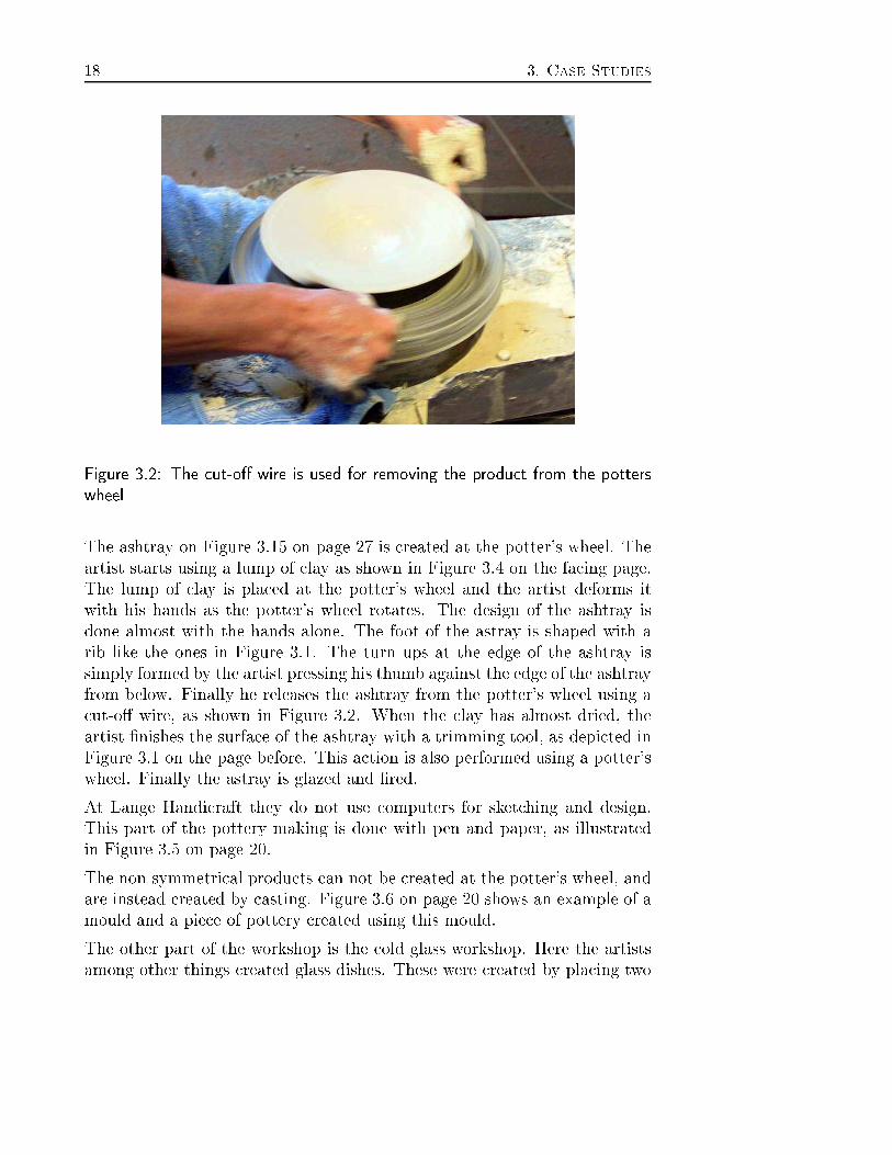
Figure 3.2: The ut-o� wire is used for removing the produ t from the potterswheelThe ashtray on Figure 3.15 on page 27 is reated at the potter's wheel. Theartist starts using a lump of lay as shown in Figure 3.4 on the fa ing page.The lump of lay is pla ed at the potter's wheel and the artist deforms itwith his hands as the potter's wheel rotates. The design of the ashtray isdone almost with the hands alone. The foot of the astray is shaped with arib like the ones in Figure 3.1. The turn ups at the edge of the ashtray issimply formed by the artist pressing his thumb against the edge of the ashtrayfrom below. Finally he releases the ashtray from the potter's wheel using a ut-o� wire, as shown in Figure 3.2. When the lay has almost dried, theartist �nishes the surfa e of the ashtray with a trimming tool, as depi ted inFigure 3.1 on the page before. This a tion is also performed using a potter'swheel. Finally the astray is glazed and �red.At Lange Handi raft they do not use omputers for sket hing and design.This part of the pottery making is done with pen and paper, as illustratedin Figure 3.5 on page 20.The non-symmetri al produ ts an not be reated at the potter's wheel, andare instead reated by asting. Figure 3.6 on page 20 shows an example of amould and a pie e of pottery reated using this mould.The other part of the workshop is the old glass workshop. Here the artistsamong other things reated glass dishes. These were reated by pla ing two

3.2. Sele ted Cases 19
Figure 3.3: A bu ket of water for leaning the hands
Figure 3.4: The lumps of lay, the artist uses for reating ashtrays

20 3. Case Studies
Figure 3.5: The artists at Lange Handi raft design their reations by sket hingthem with pen and paper
Figure 3.6: At the left the asted produ t, and at the right the mat hing mould

3.2. Sele ted Cases 21
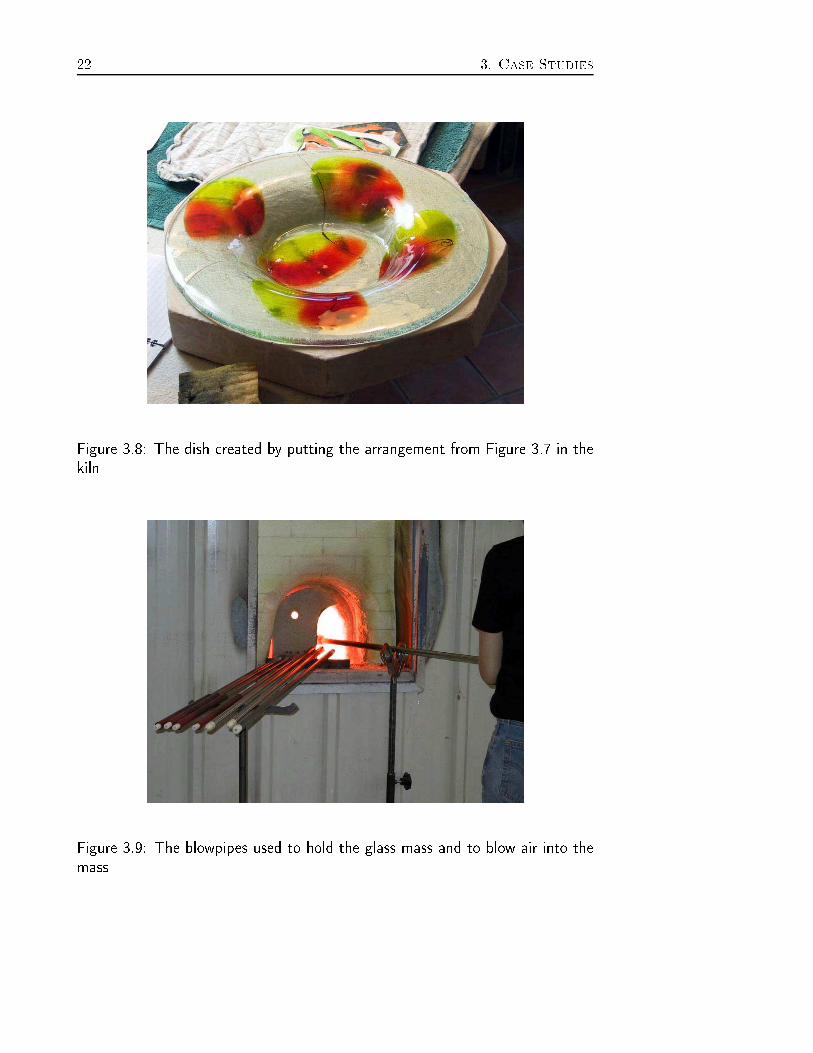
Figure 3.7: Two glass plates with olored powdered glass between on a mouldglass plates on a mould with olored powdered glass between the glass plates,as illustrated in Figure 3.7. The arrangement is then pla ed in a kiln, wherethe heated glass is pulled towards the mould by gravity. When it is �nishedin the kiln, it looks like the dish in Figure 3.8 on the next page.3.2.2 Lene Højlund GlassblowingWe also visited a glassblower3 to see another way to work with glass andwhat di�eren es there are in their hoi e of tools, if any. The fundamentaldi�eren e in the way they work with glass at Lange Handi raft and theway it is done at a glassblower, is the temperature of the glass. At LangeHandi raft they perform the work on the glass when it is room temperature,whereas the glassblower warms the glass to about 1000-1100 degrees Cel ius.For this reason the glassblowers never tou h the glass dire tly, instead theyuse di�erent tools. The tool used the most is the blowpipe, as depi ted inFigure 3.9 on the following page, whi h they hold the warm glass with anduse to blow air into the glass mass.When they have pla ed the warm glass on the tip of the blowpipe they usea big ladle to enter the mass on the blowpipe. This is a hieved by rotating3Glaspusteriet - Lene Højlund Søndergade 9A 9000 Aalborg
22 3. Case Studies
Figure 3.8: The dish reated by putting the arrangement from Figure 3.7 in thekiln
Figure 3.9: The blowpipes used to hold the glass mass and to blow air into themass

3.2. Sele ted Cases 23
Figure 3.10: The ladle used to enter the glass mass on the blowpipe, by rotatingthe mass in the ladle.the mass in the ladle, as illustrated in Figure 3.10As said earlier they an not tou h the glass dire tly due to the temperature.Instead they use a wet newspaper when they have to use the hands to shapethe glass, as shown in Figure 3.11 on the following page.Furthermore, they use a lot of di�eren e pliers for di�erent purposes. Someare for shaping the glass mass, while others are for utting the mass, asillustrated in Figure 3.12 on the next page. They also use a �at board,for instan e to shape the bottom of a glass obje t. This is illustrated inFigure 3.13 on page 25.Besides the tools, they utilize the physi al properties of the heated glass in ombination with how the environment a�e ts their reations. An exampleof this is the use of gravity to stret h and expand the glass, in ways that anbe asymmetri . This is illustrated in Figure 3.14 on page 25, where the glassobje t is rotated fast resulting in an expansion of the edge and the opening.3.2.3 3D Graphi ArtistKnowing how artists work with modeling in the physi al world, we de idedto look at the work pro ess at a omputer. For this purpose we persuaded

24 3. Case Studies
Figure 3.11: A wet newspaper is used to shape the glass when using the hands.
Figure 3.12: A small olle tion of the tools used in the pro ess of making glass reations.

3.2. Sele ted Cases 25
Figure 3.13: A �at board used to shape the bottom of a glass obje t.
Figure 3.14: A glass obje t rotated fast to expand it

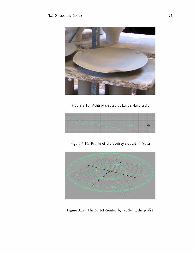
26 3. Case StudiesPeter Skotte4 to model some of the arts we have seen at Lange Handi raftand at Lene Højlund Glassblowing, in Maya.We de ided to onta t Peter Skotte based on his ba kground in 3D graphi design. He has, among other things, been working with the 3D e�e ts inTV ommer ials. He has a lot of experien e using 3D Studio Max5, Maya6and other su h appli ations. Therefore Peter Skotte an be onsidered anexpert in 3D omputer artisti graphi s, not to be mistaken for a CAD/CAMexpert. Furthermore he is urrently lo ated lose to the proje t group.We asked Peter Skotte not to be 100% a urate with size and proportions.The 3D model should just resemble the shape reated by the artists. Thisway we avoided that Peter Skotte felt it was ne essary to go into details anduse unne essary time on these.The tasks we asked him to perform involved reating the shapes shown inFigures 3.15 on the fa ing page, 3.19 on page 28 and 3.22 on page 30. Hesu eeded in ompleting ea h task with an average of about 10 minutes per�gure, resulting in the Figures 3.18 on page 28, 3.21 on page 30 and 3.24 onpage 31.AshtrayOne of the tasks we gave Peter Skotte was to model the ashtray depi tedin Figure 3.15. The �rst thing he did was to draw half of the pro�le of theashtray, as shown in Figure 3.16 on the fa ing page.Next he revolved the pro�le to get a shape whi h resembles the ashtray madeby the artist. The result of revolving the pro�le is shown in Figure 3.17 onthe next page.Finally Peter Skotte had to make the three small deformations along theedge of the ashtray. Those were the hardest thing about this task. He used adi�erent approa h for ea h of the three to illustrate di�erent ways to performthe deformation. Two of them did not give the orre t result, whereas the lasthe made was better, although he made it less wry than the deformations theartist had made. The artist used his thumb whi h resulted in a deformationthat was a little more oblique. The �nal result of this task an be seen inFigure 3.18 on page 28.4Graphi Designer at VR medialab, Niels Jernes vej 14, 9220 Aalborg Ø53D Studio Max, Dis reet6Maya, Alias Wavefront, Sili on Graphi s Limited
3.2. Sele ted Cases 27
Figure 3.15: Ashtray reated at Lange Handi raftFigure 3.16: Pro�le of the ashtray reated in Maya
Figure 3.17: The obje t reated by revolving the pro�le

28 3. Case StudiesFigure 3.18: The ashtray from Figure 3.15 reated in Maya
Figure 3.19: A vase reated at Lene Højlund GlassblowingVaseThe se ond task Peter Skotte solved was to model the vase depi ted in Fig-ure 3.19. He also started this task by drawing a pro�le and revolving it. Thefoot of the vase was shaped by pla ing some ontrol points round the edgeof the foot, these ould now be s aled loser to the enter of the vase. Thisresulted in the �ower shaped foot.The ompli ated part of reating the vase was the upper part, where thevase is separated in four quarters. This problem was solved by temporarilyremoving the lower part of the vase, and thereby avoiding the deformation onthe upper part in having an e�e t on the lower part. Furthermore the three ofthe four parts at the upper part was removed (See Figure 3.20 on the fa ingpage). Then the remaining part of the obje t were bend outwards from the

3.3. Dis ussion of Con epts 29
Figure 3.20: A quarter of the upper part of the vase, before the deformation enter of the vase. As the deformation was a omplished satisfa tory, thedeformed part was opied around the enter of the vase and the lower partof the vase was inserted again. This resulted in the obje t at Figure 3.21 onthe next page.Candlesti kThe third task we asked Peter Skotte to make was a andlesti k as illustratedin Figure 3.22 on the following page. As in the previous two tasks he �rstmade the pro�le of the shape, without the bended �at foot, and hereafter herevolved the pro�le.After he had revolved the pro�le he �attened the part of the shape that laterwould be ome the foot. Then he inserted a �skeleton� in the enter of the andlesti k, so it ould get the right bend. The �rst try to make the bendresulted in a distortion of the top part, as shown in Figure 3.23 on page 31.To ope with this Peter Skotte used �undo� to get ba k to the point beforethe insertion of the skeleton and started over. He inserted a new skeletonand bended the andlesti k, this time with a better result. The result of thetask is shown in Figure 3.24 on page 31.3.3 Dis ussion of Con eptsThis se tion dis usses the results gained from studying the design pro ess ofthe 3D graphi artist and the other di�erent artists we sele ted.

30 3. Case Studies
Figure 3.21: The vase from Figure 3.19 reated in Maya
Figure 3.22: Two andlesti ks reated at Lene Højlund Glassblowing

3.3. Dis ussion of Con epts 31
Figure 3.23: A andlesti k with distorted top, after an unsu essful bend of thefoot
Figure 3.24: The andlesti ks from Figure 3.22 reated in Maya

32 3. Case StudiesClay
Deformed clay
RotationRotation
Pressure PressurePressure Pressure
Pressure Pressure
Result
Figure 3.25: Revolve as it is used by erami artists and glass blowers is a wayof deforming the obje t3.3.1 The Revolve Pro essIn the ases we observed, the most widely used way of working with theinitial shape is based on a symmetry axis, and rotating the obje t to a hievethe desired shape. The term for this operation is �Revolve�, however the wayit is used di�ers quite a lot from the real world to the omputer system. Boththe erami artist and the glassblower use the revolve operation as a meansof deforming already existing obje ts (Deformation), whereas the 3D graphi artist uses it to reate new geometry (Constru tion).Figure 3.25 shows how a simple bowl is deformed using a potter's wheel. Theoriginal lump of lay is shaped into the �nal shape, by applying pressure onthe sides, while it rotates. Both hands are used to shape the lay, with thethumbs pressing down on top of the lay to reate the on ave inner shapeof the obje t. At the same time the thumbs are used to ounter the pressureapplied from the outside by the remaining �ngers. Glassblowers work in asomewhat similar way, only they use a olle tion of tools for shaping theglass while they rotate it using the blowpipe. So in both these ases revolveis a hieved by ombining pressure and rotation.This varies a lot from the use of Revolve on a omputer system. Here, the�nal shape is not a hieved in steps, by slowly deforming the shape. Instead,the �nal shape is de�ned by reating a pro�le (resembling one half of a rossse tion of the desired shape) and revolving it around a symmetry axis thatspe i�es the enter of the �nal obje t (See Figure 3.26 on the fa ing page).In other words, it is a pro ess that reates new geometry, and not one thatmodi�es and deforms existing geometry.To answer whether or not the erami artists and the glassblowers will �ndthe onstru tive approa h intuitive and useful will most likely require the

3.3. Dis ussion of Con epts 33Revolve
Symmetry axis Symmetry axis
Profile
Result
Figure 3.26: Revolve as it is performed using a omputer, involves reating apro�le that resembles one half of a ross se tion of the desired shapedesign and implementation of a system, followed by a thorough usabilitytest.3.3.2 The Cutting and Carving Pro essesCutting and arving, as it is understood in the traditional sense, is widelyused by erami artists as well as glassblowers. In the ase of erami s arvingis usually used for reating holes in a larger shape, adding detail to the obje tby removing and separating material from the main obje t (See Figure 3.27on the next page). Carving is also used in ases where the �ngers are too oarse for a hieving the desired shape. Cutting is not used that often, sin ethe material an be dire tly shaped into the desired shape using the handsdire tly.In a virtual environment the distin tion between utting and arving is less lear, be ause the di�eren e is only the size of the part removed from theobje t. The only way to de�ne a lear di�eren e is to de�ne utting as thea tion of separating an obje t into two new obje ts, and arving as removinga part from the obje t and dis arding the removed part.With glassblowing arving is a more ompli ated matter be ause of the ma-terial properties and the working temperature of the glass. In the studies weperformed, we did not see the method used in any of the produ ts reatedduring our visit, or exhibited in the shop. The use of regular utting is morewidespread, for a number of tasks. When a new lump of heated glass is at-ta hed to the obje t they are working on, the orre t amount is applied by utting the atta hed glass in the orre t position. Another use for utting is

34 3. Case Studies
Figure 3.27: Carving is used to add details, su h as holes, to obje ts by removingand separating materialthe reation of reases in the obje ts, for instan e to allow bending of only aspe i� part of the obje t.Using a omputer, 3D graphi artists are able to perform the same operationsas the erami artists and the glassblowers. The di�eren e is that uttingmay not be the optimal way of a hieving the same shape, be ause of howthe geometry is stru tured. This issue is related to the deformation versus onstru tion issue, in that it is sometimes easier to onstru t a desired shapein its �nal form, that it is to start out with a simple shape and graduallyapply deformations until the �nal shape is a hieved. Still, there are aseswhere utting and arving are the best and most e�e tive ways of workingout the shape of an obje t.With the omputer system, the 3D graphi artist also utilizes the uttingtools for other purposes, that are not even possible in the real world, orwould not make any sense to do in the real world. An example of this iswhen utting is used to separate a single geometry obje t into two obje ts.Although they now fun tion as two geometri al obje ts, they still fun tion asa whole, while a real obje t would have been broken by the utting operation.The main reason for utting an obje t into more parts on a omputer systemis to ontrol the a�e ted areas for other operations that are applied to theobje t. So to summarize, utting on a omputer system is used both for
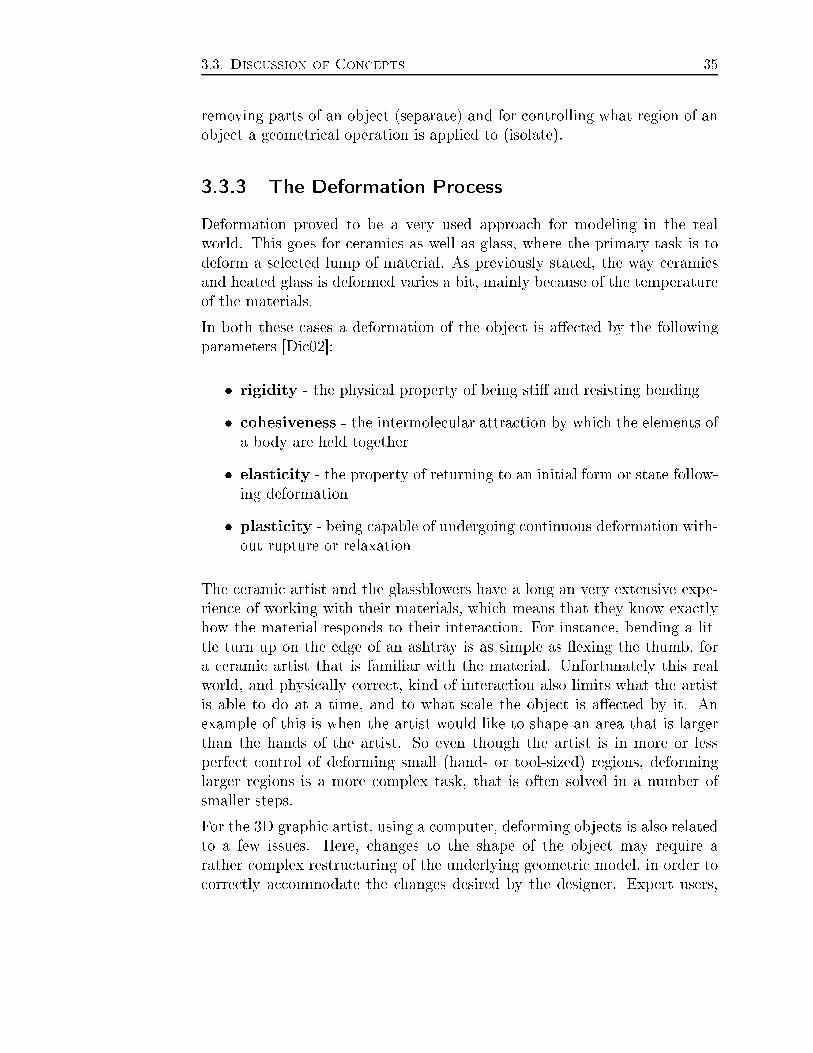
3.3. Dis ussion of Con epts 35removing parts of an obje t (separate) and for ontrolling what region of anobje t a geometri al operation is applied to (isolate).3.3.3 The Deformation Pro essDeformation proved to be a very used approa h for modeling in the realworld. This goes for erami s as well as glass, where the primary task is todeform a sele ted lump of material. As previously stated, the way erami sand heated glass is deformed varies a bit, mainly be ause of the temperatureof the materials.In both these ases a deformation of the obje t is a�e ted by the followingparameters [Di 02℄:� rigidity - the physi al property of being sti� and resisting bending� ohesiveness - the intermole ular attra tion by whi h the elements ofa body are held together� elasti ity - the property of returning to an initial form or state follow-ing deformation� plasti ity - being apable of undergoing ontinuous deformation with-out rupture or relaxationThe erami artist and the glassblowers have a long an very extensive expe-rien e of working with their materials, whi h means that they know exa tlyhow the material responds to their intera tion. For instan e, bending a lit-tle turn up on the edge of an ashtray is as simple as �exing the thumb, fora erami artist that is familiar with the material. Unfortunately this realworld, and physi ally orre t, kind of intera tion also limits what the artistis able to do at a time, and to what s ale the obje t is a�e ted by it. Anexample of this is when the artist would like to shape an area that is largerthan the hands of the artist. So even though the artist is in more or lessperfe t ontrol of deforming small (hand- or tool-sized) regions, deforminglarger regions is a more omplex task, that is often solved in a number ofsmaller steps.For the 3D graphi artist, using a omputer, deforming obje ts is also relatedto a few issues. Here, hanges to the shape of the obje t may require arather omplex restru turing of the underlying geometri model, in order to orre tly a ommodate the hanges desired by the designer. Expert users,
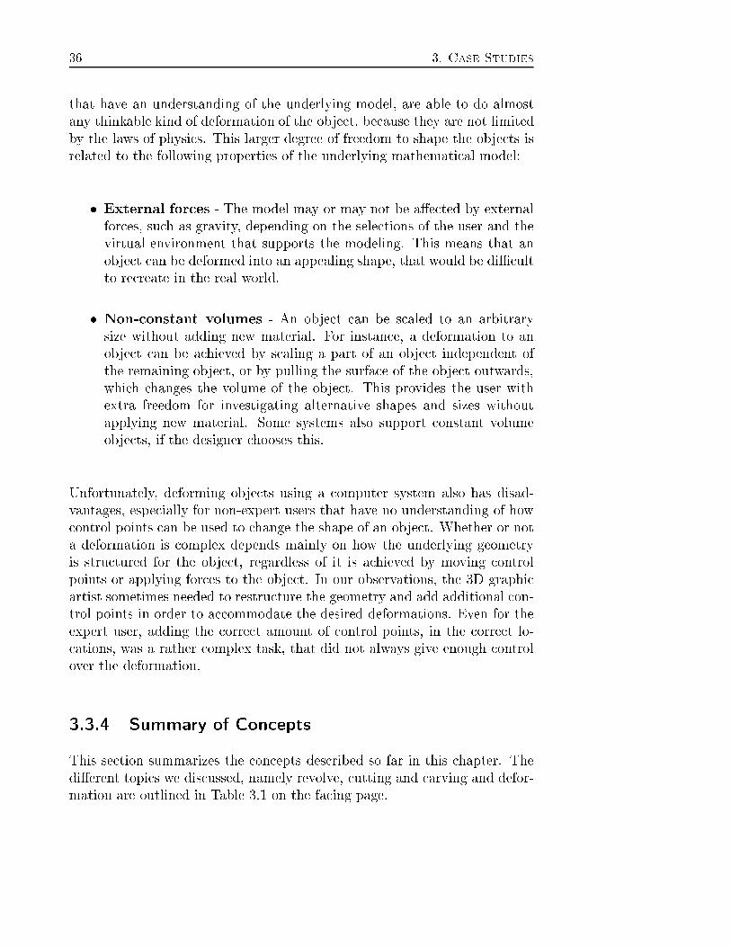
36 3. Case Studiesthat have an understanding of the underlying model, are able to do almostany thinkable kind of deformation of the obje t, be ause they are not limitedby the laws of physi s. This larger degree of freedom to shape the obje ts isrelated to the following properties of the underlying mathemati al model:� External for es - The model may or may not be a�e ted by externalfor es, su h as gravity, depending on the sele tions of the user and thevirtual environment that supports the modeling. This means that anobje t an be deformed into an appealing shape, that would be di� ultto re reate in the real world.� Non- onstant volumes - An obje t an be s aled to an arbitrarysize without adding new material. For instan e, a deformation to anobje t an be a hieved by s aling a part of an obje t independent ofthe remaining obje t, or by pulling the surfa e of the obje t outwards,whi h hanges the volume of the obje t. This provides the user withextra freedom for investigating alternative shapes and sizes withoutapplying new material. Some systems also support onstant volumeobje ts, if the designer hooses this.Unfortunately, deforming obje ts using a omputer system also has disad-vantages, espe ially for non-expert users that have no understanding of how ontrol points an be used to hange the shape of an obje t. Whether or nota deformation is omplex depends mainly on how the underlying geometryis stru tured for the obje t, regardless of it is a hieved by moving ontrolpoints or applying for es to the obje t. In our observations, the 3D graphi artist sometimes needed to restru ture the geometry and add additional on-trol points in order to a ommodate the desired deformations. Even for theexpert user, adding the orre t amount of ontrol points, in the orre t lo- ations, was a rather omplex task, that did not always give enough ontrolover the deformation.3.3.4 Summary of Con eptsThis se tion summarizes the on epts des ribed so far in this hapter. Thedi�erent topi s we dis ussed, namely revolve, utting and arving and defor-mation are outlined in Table 3.1 on the fa ing page.

3.4. Further Observations 37Ceramics
Revolve
The ceramic artist uses
the revolve operation as a means
of deforming an already existing
objects (Deformation).
Cutting and Carving
Used to remove parts of an object
(separate material). Cutting usual-
ly involves larger pieces of materi-
al, while carving is for adding de-
tail to the object.
Deformation
Deformation proved to be a very
used approach for modelling in
the real world. This goes for cer-
amics as well as glass, where the
primary task is to deform a selec-
ted lump of material. The hands
are the primary tool for deforma-
tion, since they provide a very di-
rect and powerful way of interac-
tion with the object, although at a
very limited scale.
Glassblower
Revolve
The glass blower uses
the revolve operation as a means
of deforming an already existing
objects (Deformation).
Cutting and Carving
No use of carving, mainly because
of the choice of material. Cutting
is used for applying the correct
amount of material, when two
lumps of glass are merged to-
gether (separate material). An-
other use of cutting is for creating
creases in the object, to allow
bending of only a specific part of
the object.
Deformation
The same widely usage of defor-
mation, although the glassblow-
ers use a more varied selection of
tools than the ceramic artists for
the process, mainly because of
the temperature of the material.
3D Graphic Artist
Revolve
the 3D graphic artist uses revolve to create
new geometry (Construction). This affects
other parts of his work, as he often thinks
more in terms of construction, than in alter-
ing existing objects.
Cutting and Carving
Uses cutting in the traditional way (separate
material), but also for controlling what re-
gion of an object a geometrical operation is
applied to (isolate affected regions). Often,
this cut is temporary, and may be removed
when the wanted operation is applied to the
given region of the object.
Deformation
Deformation can be applied at a larger scale,
but may require complex restructuring of
the underlying geometric model (expert
knowledge). Control of external forces and
constant or non-constant volumes during
deformation. Getting adequate control over
some deformation may be very difficult,
even for expert users.
Comparison of Concepts
Table 3.1: An overview of the dis ussed on epts for erami artists, glassblowersand 3D graphi artists3.4 Further ObservationsThis se tion dis usses further observations made during the ase studies,in luding work pro esses, immersiveness, and the notion of an intera tionloop.3.4.1 Di�eren es in Work Pro essesThe artist working in the physi al environment has a very di�erent approa hof modeling the desired obje ts ompared to an 3D artist, and as a result theyhave ease and di� ulties arrying out di�erent tasks. Both kinds of artist an easily reate simple organi geometri shapes by their way of revolving.A big di�eren e appears when for instan e the turn ups on the ashtray fromFigure 3.15 on page 27 are to be reated. The erami artist reates theturn ups with ease, partly due to the fa t that it is a simple task, andpartly be ause of his skills and experien e. The 3D artist on the other hand,

38 3. Case Studieshad some di� ulties in a hieving the same deformation, even though helikewise has extensive experien e with his work. The task for the 3D artistis ompli ated, be ause he has to make hanges in the underlying geometri stru ture in the obje t to make it behave orre tly.The 3D artist had relative ease in reating the andlesti ks in Figure 3.22 onpage 30, by simply deforming an relatively simple obje t. The glassblowerhad some di� ulties by reating the andlesti ks. The problem is the ma-terial properties of the heated glass. A ording to the glassblower, the glasshas �a will of its own� and if it �rst �de ides� to deform in a given dire tion,the pro ess is irreversible. Also, the glass gets sti�er as it ools down, and ontinuously hanges material property along with the ooling, so there isa time limit in whi h the glass an be worked with. This restri tion doesnot apply to the 3D artist, that an experiment with the shaping of the andlesti ks at his own pa e.3.4.2 Immersive EnvironmentsThe work pro ess of the erami artist was mainly to deform simple primitiveswith his hands as he was ontrolling the rotation of the obje t with a footpedal. Furthermore, he used a few tools to manipulate the �ner details of theobje t. The glassblower has another approa h for working with his obje tsdue to the extreme temperature of the obje t. The initial idea of deformingan obje t is the same as with the erami artist, but a di�eren e is that theglassblower uses one hand as a primary hand and the other hand as se ondary.The se ondary hand is only used as support for the blowpipes and for rotatingthem. The 3D graphi artist also used a primary and se ondary hand, theprimary for drawing with the mouse, navigation plus hoosing menu itemsand buttons. The se ondary hand is used for hoosing how to navigate inthe environment, for short ut keys and for opening a hotbar with fast a essto a lot of the program fun tions.For all ase studies, the environment does support them in the design pro- ess. The erami artist and the glassblower both organize their workingpla e to support the whole working pro ess. This is a hieved by physi alarrangements that simpli�es or eases the work pro ess of reating their art.The 3D artist also adjusts his workspa e to ease and support his work �ow.He a hieved the adjustment by sele ting the layout of the user interfa e inthe appli ation he uses. For instan e, the level of detail to show in the hotbox in Maya an be adjusted.

3.4. Further Observations 39Minds
eyeModel
SeeFigure 3.28: The intera tion loop a user enters, when modeling3.4.3 Intera tion LoopAs des ribed in Se tion 2.1 on page 9 drawing is an iterative pro ess, sin einitial lines guide the eye to more pre ise lines, and so on. This may also applyfor other kinds of artisti shape design, be it onstru tion or deformation,be ause the eye also gets the feedba k from the initial reation in these ases, whi h enables the user to adjust it to something loser to the desiredresult. This iterative pro ess is illustrated in Figure 3.28, whi h is based onthe iterative prin iple in Figure 2.1 on page 10. The �gure illustrates thatthe user models the obje t from the minds eye. The obje t then feeds theeye with input. Hereafter, the user ompares the result from the modelingpro ess with the expe ted result from the minds eye. The di�eren es areevaluated and the user orre ts the obje t. This loop ontinues until theuser de ides that the reation is �nished. In some extreme modeling aseslike glass blowing, reshaping of the obje t in progress is not possible, so theiterative part of this modeling type is to reate a new obje t from a newlump of glass, but with the experien e from the failed obje t in mind. Byusing the experien e from the failed obje t, the iterativeness of the pro essis maintained even here. This shows that modeling has an intera tion loop,for re�ning the resulting obje t.


4 Guidelines for Paradigm
SelectionBased on the observations and onsiderations made in Chapter 3, we are a-pable of setting forth a number of guidelines for hoosing modeling paradigms,that are suitable for artisti shape design.We des ribe three major areas of re ommendations that, as a whole form thebasis for designing the intera tive modeling appli ation. These areas in ludeguidelines on erning fun tionality, intera tion and the underlying platformwith regards to both software and hardware.4.1 Fun tionalityThis area overs the following topi s:� What kind of modeling should be supported for the user in using theappli ation?� What paradigms orrespond to the requirements of supported modelingtasks?The system should, as a minimum, be able to support the user in re reatingthe obje ts from the ases we observed. To do this, the following guidelinesshould be ful�lled:� Constru tion of new geometry in the system� Deletion of geometry, for instan e by using an eraser

42 4. Guidelines for Paradigm Sele tion� Cutting and arving� Deformation� Supporting geometri routines - revolve, extrude, s ale and mirroringBased on the analysis performed, a sele tion of modeling paradigms, that orrespond to the tasks des ribed above, should be hosen. To a hieve this,a wide sele tion of related work in the area of intera tive modeling should beinvestigated, in order to identify those best suited for our appli ation.4.2 Intera tionIntera tion overs the following topi s:� User Interfa e - whi h of the following should be used to intera t withthe system and swit h between the implemented fun tionsÆ Dire t manipulation/Dire t intera tionÆ MenuÆ ToolbarÆ GestureÆ Audio� Input Devi es - whi h kind of hardware input devi es should be a es-sibleÆ Data gloveÆ WandÆ PenIntera tion with the appli ation is of ru ial importan e, and one of the mainreasons for moving the design pro ess from an ordinary desktop omputerto a more suited virtual environment. Furthermore, intera tion is exe utedin loops as illustrated in Figure 3.28 on page 39, and therefore this prin iplemust be supported by our intera tion method.With the inexperien ed users in mind, the user interfa e should be as simpleand straight-forward as possible. Di�erent users may have di�erent prefer-en es with regards to the usage of gestures and audio feedba k for instan e,

4.3. Platform 43but ideally they should be able to hose the method they prefer. The use ofmore advan ed intera tion te hniques, su h as gestures and audio, will inher-ently a�e t the sele tion of hardware and how the underlying platform forthe system will be designed. Therefore, these onsiderations will be in ludedwhen the appropriate hardware is sele ted for intera tion devi es and theplatform that should support the di�erent kinds of intera tion paradigms.The sele tion of input devi es should be made with intuitive intera tion asone of the primary goals. Also, they should be omfortable to use and allowthe user to express the shapes they imagine, without indu ing unne essary ognitive overhead. In other words, the input devi es should support a natu-ral �ow of thoughts and the reation of new ideas. This is also stated in thetheory of ready-at-hand and present-at-hand, whi h tells that a tool that isready-at-hand is transparent to the user, so he an on entrate on the a tualwork. If the tool only is present-at-hand, the user pays attention to the tool,and will therefore be hindered in an optimal work �ow, as the tool takessome of his time [DM93℄.The pre ise sele tion of whether the best suited input devi e is a glove, wandor pen depends on the a tual use ontext, the intera tion paradigm and ertainly also the modeling paradigm, that for instan e may require a dataglove. Re ommendations should be made on the di�erent ombinations, anda usability test may be performed to verify the results, with fo us on theuser's point of view.4.3 PlatformThis area overs the following topi s:� Software - what software should form the basis software platform forthe intera tive modeling appli ation� Hardware - whi h hardware ould be ompatible with the appli ationopenNURBS [MA00℄ will be a suitable tool for handling the basi s graphi sfun tions, preventing that we need to implement every graphi fun tion froms rat h. We have hosen openNURBS partly be ause its free, and partly be- ause we have seen some impressive implementations based on openNURBS.VR Juggler [Tea01℄ has the advantage of being apable of exe uting on astandard workstation as well as the Cave Automati Virtual Environment

44 4. Guidelines for Paradigm Sele tion(CAVE). This gives us the possibility of developing our appli ation at aworkstation, and then later exe ute the appli ation in the CAVE. Further-more VR Juggler is open sour e. A more detailed des ription of VR Juggler an be found in Appendix A.The visualization should be realized by a Head Mounted Display (HMD) orin the CAVE, be ause a desktop omputer not will be able to provide theuser with the orre t 3D visualization. The hoi e of VR Juggler providesus with the freedom to develop on a desktop omputer and then move theappli ation to the CAVE or a HMD later. This means that the hoi e ofvisualization devi e an be postponed to later in the development. The hoi eof intera tion is more ru ial at this time, be ause there will be extensivedi�eren es in the design of the intera tion depending on the hoi e of a dataglove or a wand. Furthermore the hoi e of hapti feedba k or audio feedba kwill be essential for the design of the intera tion.

5 Related Work
This hapter presents an overview of resear h and literature that is relatedto the ontext of our proje t, namely Intera tive 3D Modeling and Artis-ti Shape Design. The paradigms from these studies are divided into thefollowing groups:� Constru tion - paradigms on erning reation of new geometry.� Deformation - paradigms that in some way hange existing geometry.� Hybrid - paradigms that are mainly a ombination of the other two.Also, ea h paradigm is dis ussed and evaluated with regards to the ontextof our proje t, and the issues we identi�ed in the analysis in the previous hapters.Table 5.1 on the next page presents an overview of the di�erent paradigmsen ountered through our studies of literature. In the table these are dividedinto the groups des ribed above. Furthermore, they are divided into polyg-onal or parametri depending on whi h of these data stru tures they makeuse of. This table is made to give an overview of whi h paradigms an be ombined in one appli ation without the need to translate from polygonal toparametri or visa versa.In [DBW+00℄ Joa him Deisinger et al. presents the results of a workshopwhi h tested three di�erent prototypes of intera tive modeling appli ations.Sin e this is not a paradigm it is not pla ed in one of the previous des ribedgroups nor is it a part of the table above. The results are based on thefeedba k from 36 design professionals. The analysis of these results and their

46 5. Related WorkPolygonal Parametri
Constru tion Surfa e Drawing by StevenS hkolne et al. ([SS99℄,[SPSa℄, [SPSb℄)Teddy: A Sket hing Inter-fa e for 3D freeform de-sign by Takeo Igarashi et al.([IMT99℄)3-draw: A Tool for De-signing 3D Shapes byEmmanuel Sa hs et al.([SRS91℄)
DeformationSkin: A Constru tiveApproa h to ModelingFree-Form Shapes byLee Markosian et al.([MCCH99℄)inTou h: Intera tive Mul-tiresolution Modeling and3D Painting with Hapti Interfa e by Arthur D.Gregory et al. ([GEL00℄)
Dire t Manipulation ofFFD: E� ient Expli itSolutions and De omposibleMultiple Point Constrainsby Shi-Min Hu et al.([HZTS01℄)Preventing Self-Interse tionUnder Free-Form Deforma-tion by James E. Gain andNeil A. Dodgson ([GD01℄)Hybrid (None found) Collaborative Geometri alModeling in ImmersiveVirtual Environments byM. Usoh and T. I. Vassilev([USV96℄)An Interfa e for Sket hing3D Curves by Jonathan M.Cohen et al. ([CMZ+99℄)Table 5.1: An overview of the paradigms presented in the studied literature

47experien e with the systems will be useful in improving intera tive modelingappli ations and further development in this area in general.The paper states that modeling in virtual environments has the potential tobe more powerful than existing modeling appli ations on desktop systems.However, an e�e tive, user-friendly immersive modeling tool has yet to bedeveloped. Resear h areas in lude the exploitation of human �ne motor skillsand de iding what level of fun tionality is suited for intera tive modeling inimmersive environments. During the workshop insight was gained into howparti ipants a t during the design pro ess, with regards to work-time, usageof tools and so forth.The workshop identi�ed three distin t phases during a design:� on eptual phase: ideas, thoughts and their �rst visualization,� elaboration phase: working out alternatives; the quanti� ation anddetailing of sket hes and models and� presentation: working out the ultimate shape, hara ter and fun tionof the on ept for the general publi .One of the important results from the workshop, is that urrent intera tivemodeling tools, only over the on eptual phase and at most early stages ofelaboration. The main reason for this being that no spe i� tool is able toprovide users with the appropriate level of fun tionality and ease-of-use tospan all the phases of a design pro ess. On the topi of ease-of-use, the toolsshould fun tion in a way that supports a natural �ow of thoughts and the reation of new ideas.Sket hing has until now, been an important part of the on eptual phase, butthe most widely used tool for this is a regular pen il and a pie e of paper.Although it may seem to be a simple kind of intera tion, the �paper andpen il� metaphor has proved to be a very powerful tool. However, traditionalsket hing is an inherently two-dimensional a tivity. Therefore, the workshopinvestigated the possibility of extending sket hing to three dimensions.The three phases identi�ed in the workshop are useful for setting the s ope ofthe intera tive modeling appli ation that we will design. Most of the resultsfrom the workshop will serve as re ommendations for how users will inter-a t with the appli ation. Their re ommendation of the �paper and pen il�metaphor orresponds well to our point of view (as mentioned in Chapter1 on page 4) for systems that are intuitive and easy to learn. One of themore promising systems that have extended the pen and paper to 3D, is theSurfa e Drawing system whi h we will dis uss later in this hapter.

48 5. Related Work5.1 Constru tion ParadigmsIn [SS99℄, [SPSa℄ and [SPSb℄ Steven S hkolne et al. presents a on ept alledSurfa e Drawing. Surfa e Drawing addresses several issues in reative ex-pression and per eptual thinking by providing a dire t link between the mo-tions of the hand and the forging of shapes. Surfa es are reated by movingthe hand, whi h is instrumented with a glove, through spa e. The drawingpro ess is illustrated in Figure 5.1, where a user is drawing in 3D spa e.A ording to the arti les, this te hnique allows both novi es and experts to reate forms without the per eptual onstraints of a mathemati al stru tureor a large toolset.Using this on ept no forward planning of the onstru tion is needed. Thedesign spa e an be freely explored during the modeling pro ess. It supportsun onstrained erasing and buildup of new geometry, and allows the user tofreely grow, join and erase surfa es based on the hand motions.
Figure 5.1: A user draws in 3D spa e using the Surfa e Drawing systemThe Surfa e Drawing method omes a ross as a method that is very simpleto learn, in that it provides a one-to-one mapping between the gestures of

5.1. Constru tion Paradigms 49a user, and the resulting geometry. We believe that the method is easy tolearn, and that it is suited for experimentation, be ause users are able todelete geometry the same way they would use an eraser with the lines they reated using a pen il. Only, the on ept of paper and pen il is extended to3D in this ase.Surfa e Drawing is well suited for sket hing the initial ideas of a designer,and for qui kly reating alternative shapes in the early stages of the designpro ess. This �ts perfe tly together with the ontext and s ope we set forour modeling appli ation, and the sele tion and skill of the users that aresupposed to use the appli ation. The users do not have to think about theunderlying mathemati al stru tures, su h as oordinate systems and on-trol points, in order to model interesting shapes using the Surfa e Drawingmethod.But, on the other hand, the simple intera tion also has some limitations,most of whi h are related to the speed of the method, that is in�uen edby the one-to-one mapping of the hand gestures. For instan e, reating asurfa e that has a large number of S-shaped urves that follow ea h other, an be a large and somewhat tedious task to perform using only surfa edrawing. Instead it ould be ombined with geometri operations su h asrevolve, sweep and extrusion in order to speedup the reation of some typesof obje ts. Fortunately, this issue does not mean that the least experien edusers will be unable to reate the desired shapes, but only that they will takemore time to get the job done.In [IMT99℄ Takeo Igarashi et al. presents another onstru tion paradigm alled Teddy. It enables the user to reate 3D obje ts by drawing 2D freeformstrokes. The freeform stroke is losed as a silhouette, and from this silhou-ette the appli ation reates a 3D polygonal surfa e. A region is in�ated bymaking wide areas fat and narrow areas thin. An example of an obje t being reated in Teddy is shown in Figure 5.2 on the next page. The geometri representation of the polygonal surfa e is a standard polygonal mesh.The appli ation an reate, ut, erase, paint, extrude, bend, smooth andtransform obje ts.Teddy provides users with an easy-to-learn way of reating 3D obje ts, whi his a wanted property with regards to the system we will design. Most ofthe ideas are quite simple, and easy to ontrol using the pen-like intera tiondevi e, but the user is quite limited in the shapes that an be reated. Shapesthat are di� ult to reate, in lude re tangular shapes and obje ts with sharpedges.

50 5. Related Work
Figure 5.2: An obje t being reated in the Teddy appli ation. In the �rst pi turethe initial 2D stroke is drawn. In the se ond pi ture, the obje t has been in�atedto an 3D obje t, and �nally the last pi ture shows the 3D obje t rotated, tobetter show the shape of itThis means that an approa h that is similar to Teddy an be used for the ini-tial design stages of organi shaped obje t, mainly by non-expert users thatare just learning to use the system. For more omplex shapes, that require alarger degree of freedom, geometry should be reated using another onstru -tion approa h, or by deforming the obje t using some kind of deformationparadigm.In [SRS91℄ Emmanuel Sa hs et al. presents a way to design 3D shapes bysket hing. They present an appli ation that provides a virtual approa h tothe design sket hing, that often is done on paper before a digital drawing is reated. The appli ation uses a pair of six-degree-of-freedom input devi es,one held in ea h hand. In the primary hand the user holds a pen, by whi hhe is drawing in free spa e, and in the other hand he holds a palette whi his lo ked to the global oordinate system for the obje ts he draws. In thatway the user an turn the obje t he is drawing with the se ondary hand.The shapes are onstru ted in four steps:1. The urves are sket hed dire tly in 3D2. The urves are edited by deformations3. The surfa es are �tted to groups of linked urves4. The surfa es are deformed to obtain the desired detailThe intera tion should be intuitive to the user, be ause there is a one-to-onemapping of hand motions to virtual obje t motions.

5.2. Deformation Paradigms 51The prin iples in 3-Draw allows the user to draw with a one-to-one mappingdire tly in 3D with the possibility of moving the drawn obje t in 3D spa eusing the se ondary hand. The most obviously limitation of the method, isthe restraint in the size the drawing an have. This size is limited of therea h of the user. The prin iple of drawing dire tly in 3D spa e seems veryintuitive, as the user simply draws dire tly the wanted drawing. Even thoughthe four step approa h an perhaps be a little ounterintuitive, it should bepossible to adapt to.5.2 Deformation ParadigmsA well known deformation paradigm is Free-Form Deformation (FFD). Thisparadigm an best be des ribed by using a jelly metaphor. The obje t tobe deformed is wrapped inside a jelly-like substan e. To deform the obje t,pressure is applied on the outside of the jelly and the obje t is deformedalong with the jelly.To many, this is very ounterintuitive and for this reason Dire t ManipulationFFD (DMFFD) was introdu ed. This method provides the users with anextra abstra tion layer on top of regular FFD. The di�eren e is that the userdoes not have to know the mapping from the deformation of the jelly tothe deformation of the obje t. Instead the user dire tly deforms the obje tsurfa e and the system then al ulates the jelly's deformation to satisfy thedesired obje t deformation.Without using the metaphor, FFD is a deformation method where the usermanipulates ontrol points to make the deformations of the obje t surfa e,whereas DMFFD allows the user to work dire tly on the obje t surfa e.When a point is moved on the surfa e the system al ulates the ontrolpoint positions that ful�ll the surfa e point movement. Then these new ontrol points is applied using standard FFD, like if the user had moved the ontrol points manually.DMFFD is illustrated in Figure 5.3 on the following page, where a half moonis put inside the �jelly�. The deformation is made at the lower tip of the moon,whi h is pulled downwards. The system then al ulates the orrespondingjelly deformation to a hieve the deformation of the obje t. The main problemwith DMFFD is that it is very omputational heavy and not really suited forreal time appli ations.

52 5. Related Work
Figure 5.3: An obje t deformed by DMFFD. Pushing or pulling a point on thesurfa e of an obje t deforms the surrounding jelly-like shell, that propagates thedeformation to the obje t inside itThis problem is studied by Shi-Min Hu et al. in [HZTS01℄, where an al-ternative, and less omputational omplex, method to perform DMFFD ispresented. Other methods are based on omputing the pseudo-inverse ma-trix, whi h involves ompli ated al ulations. The solution presented in thisarti le solves the dire t manipulation problem by using a onstrained opti-mization method and thereby obtains an expli it solution. This only involves,a ording to the arti le, simple al ulations. In addition they also show thatmultiple point onstraints an be de omposed into separate manipulation ofsingle point onstraints.Unfortunately, FFD and DMFFD only works with parametri surfa es. Thismeans that surfa es, su h as those reated with Surfa e Drawing, an notbe dire tly used together with DMFFD, sin e Surfa e Drawing is based ona polygonal model. This requires a onversion of the polygonal model to aparametri surfa e, using either surfa e �tting or approximation.Another problem that often arises when using (DM)FFD is one known asself-interse tion. Self-interse tion is when the obje t after a deformationinterse ts itself.This problem is studied by James E. Gain and Neil A. Dodgson in [GD01℄.A ording to them Self-Interse tion, and how to prevent it, is very over-looked in the 3D modeling ommunity. Two approa hes for preventing Self-Interse tion under both FFD and DMFFD are presented.The �rst approa h is a pre ise dete tion of Self-Interse tion, but it is very omputational omplex and therefore not suited for real time appli ations.

5.2. Deformation Paradigms 53The other approa h is a su� ient dete tion that is more suited for real time.Both approa hes makes use of a inje tivity test to dete t if a wished defor-mation will result in Self-Interse tion, by he king for one-to-one mapping.The inje tivity test he ks if all points on the surfa e before the deformationwill map to a unique new position after the deformation, hen e one-to-onemapping. This se ures that the deformation do not ause self-interse tion,sin e a self-interse tion will result in at least two points at the surfa e sharingthe same oordinates in spa e, and thereby they do not have a one-to-onemapping.This approa h to prevent Self-Interse tion, will indire tly limit the user'sfreedom and to avoid this the arti le presents a solution alled AdaptiveSubdivision for DMFFD. In this solution the wished deformation is � hopped�up in half, whi h then will be arried out individually. If these two newdeformations still result in Self-Interse tion the pro ess is repeated. This ontinues until either a maximum number of divisions is a hieved or theresulting deformation is not Self-Interse ting.Another form of deformation paradigm, named Skin, that an make polygo-nal models smother by re�nement of the surfa e, is presented by Lee Markosianet al. in [MCCH99℄. Skin is a parti le-based surfa e representation that en-ables the user to intera tively s ulpt free-form surfa es. An important aspe tof the Skin approa h is the use of subdivision surfa e theory. Based on a setof rules they de�ne, the parti les form triangulations, that make them suit-able for applying subdivision. Figure 5.4 illustrates an obje t whi h after adeformation would result in Self-Interse tion. Therefore the deformation isaltered by Adaptive Subdivision so Self-Interse tion does not o ur.Figure 5.4: An obje t whi h after a deformation would result in Self-Interse tion.Therefore the deformation is altered by Adaptive Subdivision so Self-Interse tiondoes not o ur.Based on a olle tion of skeletons, whi h they refer to as polyhedral elements,a smooth surfa e is reated by growing the parti les, or skin, using a subdi-

54 5. Related Workvision s heme that approximates the underlying skeletal shapes. Figure 5.5illustrates two di�erent triangulations of a surfa e. The Skin system is a partof an e�ort to reate a free-form modeling system, that via dire t intera tionallows a user to de�ne shapes by sket hing the shape and its proportions.
Figure 5.5: The same obje t triangulated in two di�erent ways. The Skin system an rede�ne this triangulation for a smoother result. In pi ture (a) an impropertriangulation is used, that results in the obje t surfa e in pi ture (b), for instan ethe rease between the two lower se tions inside the obje t is unintended. Inpi ture ( ) another triangulation is used, whi h results in the learly better resultin pi ture (d)The idea behind Skin is to take a simpli�ed polygonal model, and reate omplex surfa es based on the polygonal model, resulting in a smooth surfa ethat approximates the underlying polygonal model. The Skin system is wellsuited for rapid onstru tion of approximate free-form surfa es, meaning thatit annot provide exa t ontrol of the �nal shape. This means that it an beused during the reative pro ess of designing and shaping a produ t, but notin the �nal produ tion pro ess, where traditional CAD a ura y is required.As the Skin system takes a simpli�ed polygonal model as basis, it is notsuitable for reating new geometry. Instead, Skin is useful ombined withparadigms su h as Surfa e Drawing, in order to smoothen a rough polygonalmodel, and to add details using the notion of reases, that the Skin systemintrodu es.With regards to ease-of-use, the reases an be drawn using a pen-like devi eon the surfa e of the obje t. Moving the rease to perform the deformation ould then be a hieved by grabbing the rease with a data glove (See Fig-ure 5.6 on the next page). This should allow new users to utilize this kind ofdeformation, sin e the intera tion and ontrol of the deformation pro ess isfairly dire t.

5.3. Hybrid Paradigms 55Crease
Surface New location of crease
Previous location of creaseFigure 5.6: To the left the initial line des ribing the ourse of the rease isdrawn. To the left the initial line is moved, and has thereby drawn the surfa edown resulting in a reaseAnother approa h to the re�nement on ept, alled inTou h, is presented byArthur D. Gregory in [GEL00℄. inTou h an be used as a geometri modelerbased on simple loaded primitives, a �nishing system by for instan e reatingsharp features and �ner details or as a painting tool where olor and textures an be painted dire tly to the model's surfa e.When modeling, the user hooses the resolution and atta hes a probe to thesurfa e. The hanges are propagated up a ording to subdivision rules tothe highest level of the mesh. At the user interfa e, a tual deformations isa omplished by pressing and releasing a button when in onta t with thesurfa e.inTou h is similar to Skin in that it also allows the user to take a relativelysimple polygonal model, and hange the shape of the obje t and add detailby deforming it. Therefore, inTou h also ombines ni ely with systems su has Surfa e Drawing. However, with inTou h it is also possible to load simplegeometri shapes as a basis for the deformations. An interesting propertyof inTou h is the use of a hapti interfa e, that provides feedba k to theuser from the intera tion with the system. Unfortunately their setup, witha pen-like devi e atta hed to a roboti arm, has a very limited range. Thismeans that the hapti interfa e they developed, is not dire tly suited forlarger immersive environments like those that utilize the CAVE system.5.3 Hybrid Paradigms[USV96℄ by M.Usoh and T. I. Vassilev fo uses on building an intera tivemodeling appli ation from a ollaborative point a view. An important goal of

56 5. Related Workthe appli ation is to provide tools whi h are intuitive and easy to use, allowingthe designer to use natural hand motion to sweep out omplex surfa es andintera tively deform and reshape them.The mathemati al base of their work is a mixed geometri al-physi al ap-proa h that ombines bi- ubi B-Splines with models of material propertiessu h as rigidity, ohesiveness, elasti ity and plasti ity. This information isused to ensure that the surfa es will deform in a well de�ned manner whena user applies a for e to the surfa e.Although parametri surfa es, su h as the sele ted bi- ubi B-Splines sur-fa es, are a very powerful tool for geometri modeling, the traditional in-tera tion through movement of ontrol point is neither an elegant nor anintuitive way of intera tion with the surfa e. An example of this is that evenwith a single bi- ubi pat h, the user must deal with 16 ontrol points. Al-though, after an extended period of time using the system, they believe thata user will be ome more aware of the relationship between the shape of asurfa e, and the pla ement of ontrol points.With their mixed geometri al-physi al model however, the following a tions an be performed on a surfa e, without dire tly intera ting with the ontrolpoints:� Deformation through applying a single or a set of for es;� Deforming a urve embedded on the surfa e;� Deforming an area of the surfa e;� Moving a single point from the surfa e to a new position;� Moving a surfa e urve to a new urve in spa e.New surfa es an be reated intera tively, by using a wand-like tool, as theuser sweeps out a shape in 3D spa e, a surfa e is reated su h that it inter-polates the spa e the user spe i�ed. They des ribe this pro ess as turningthe kineti energy of a user into visible surfa es - turning a sweeping gestureinto something on rete.Unfortunately they were not able to get the kind of performan e they wereaiming for, sin e given the urrent implementation and hardware-setup, thesurfa es will jump to their new shape when a for e is applied. Instead, theywould have liked the surfa e to deform ontinuously, in a rubber band fashion,as the for e is being applied. However, they are on�dent that this will bepossible in future versions of their appli ation.

5.3. Hybrid Paradigms 57The system they designed deals with both onstru tion and deformationtopi s, whi h gives the user a great deal of freedom with regards to theway they prefer to model. Although their features are impressive, our main on ern is the performan e issues they outlined. No matter how lever andintuitive a modeling paradigm may be, we believe that ontinuous feedba kis a very important aspe t of intera tive modeling, be it visual or hapti .In their ase they failed to a hieve what they all the �rubber band� e�e t,where surfa es deform ontinuously. The ideas behind their system, and theuse of parametri surfa es, seem very appealing if the performan e an beimproved to provide ontinuously feedba k to the user.In [CMZ+99℄ Jonathan M. Cohen et al. presents a method for spe ifying 3D urves with 2D input from a single viewpoint. They laim that even thoughsket hed urves are impre ise by nature, sket hing allows a user to qui kly reate a urve that is lose to the desired result. A trained artist shouldhave the ability to produ e a urate urves with his existing drawing skills,be ause the interfa e mat hes losely to pen il and paper.The te hnique presented in this arti le falls in the ategory of dire t ma-nipulation of spline urves. The urves are sket hed in two strokes: �rst aestimated urve, and then a stroke on a surfa e for instan e under the urve.The stroke under the urve represents the shadow of the urve and thereby an the orientation of the urves depth be indi ated.Four basis methods for sket hing urves are supported:� Drawing a new urve on some plane� Overdrawing a se tion of an existing urve� Rede�ning a urve's entire shadow� Overdrawing a urve's shadowFigure 5.7 on the following page illustrates the drawing of a urve and then ashadow for the urve, and �nally an overdraw on the urve. The user hoosesbetween urve mode and shadow mode. The system determine that a strokeis an overdraw if the stroke starts and ends near a existing line, and is nearlyparallel with this. The shadow ould be proje ted in another dire tion, su has a wall plane. Furthermore the proje tion ould be done at a terrain.

58 5. Related WorkFigure 5.7: A urve is drawn, a shadow is added, and �nally the urve is over-drawn.We have some doubt about the intuitiveness of this approa h, sin e the tradi-tional way to draw something 3D-like on a 2D-plane is to draw in perspe tiveand then add shadows. It seems somehow a bit awkward to de�ne the depthof the drawing based on the shadow, and the shadow would likely be di� ultto draw orre tly based only on the urve and the pi ture from the mindseye (See Se tion 2.1 on page 9).
Figure 5.8: The four viewpoints from the graphi al user interfa e in Maya

5.3. Hybrid Paradigms 59The idea about drawing 3D in 2D with only one viewpoint ould be inter-esting, among other things for making the user interfa e more well-arrangedthan the traditional four viewpoints (See Figure 5.8 on the fa ing page),known from for instan e Maya and 3D-Studio Max. The urve-shadow ap-proa h seems to have a limitation; if the user for instan e wishes to draw two lose parallel lines, he will end up with an overdrawn line instead.


6 Analysis Summary
This hapter summarizes upon the Analysis part, and presents further elab-orations of the topi s dis ussed in this part.We did some studies regarding drawing prin iples whi h we found reallyuseful, to get a good insight into how a 2D drawing an be a hieved. Thesestudies of drawing prin iples provided us with some basi knowledge in theart of drawing. We on luded that these prin iples ould be mapped to an 3Denvironment, in whi h we draw surfa es. This similarity made it likely thatthe power of the paper and pen paradigm ould be utilized in our ontext.In the analysis we also did some �eldwork, where we studied how artistsfrom di�erent artisti trades performed their work. We believe this was avery good knowledge base for the proje t, be ause we got a good insightinto how potential users would use the appli ation, and what kind of toolsthey might be needing. Furthermore we observed that the erami artistand the glassblower worked using the deformation paradigm, and the 3Dexpert worked using the onstru tion paradigm. The erami artist andthe glassblower is for ed to start with the deformation paradigm, be ausematerial does not materialize from thin air. This is not the ase for the 3Dartist, sin e he an reate obje ts from nothing. One small drawba k in theperformed �eldwork was our hoi e of artists. Without further elaboration,we hose artists who all worked with reating art that in some way was entered around an axis. Be ause of this, the tasks we asked the 3D graphi designer to perform, indire tly had him designing around an axis too.We feel that it would have been a good idea to study other artisti trades,whi h do not work around an axis, su h as s ulptors, and painters. A painterwould probably also give us additional knowledge in drawing prin iples whi hwe studied only in literature. We believe that s ulptors would give us two

62 6. Analysis Summarydi�erent approa hes for reating obje ts. Some s ulptors would reate artby starting out with an obje t, whi h is bigger than the size of the desiredresult, and whi h often is made of stone or granite. He would then removeparts and pie es of the initial obje t by utting and arving until he rea hesthe result he was aiming for. Other s ulptors would go the other way around,and start with an initial obje t whi h is smaller than the �nal result, andwhi h often is made of lay or a material like it. He would then start addingsmall individual pie es until the desired result is rea hed.It would also have been a good idea to study other omputer designers,working with eg. CAD/CAM, as a supplement to the 3D graphi designer.This is something that de�nitely is worth looking at in future proje ts of thiskind.Furthermore, we studied literature to gain knowledge in the area of inter-a tive 3D modeling. Espe ially, we needed to identify paradigms related toour proje t, so we had a better foundation for hoosing paradigms, whi hwe believed ould ful�ll the demands we found through the ase studies. Welearned that in this area, resear h is moving forward quite fast. Most ofthe literature we studied was a maximum of a few years old. So for futurework, further and ontinuous studies of related literature would be a goodidea to keep up with new initiatives and paradigms. By studying relatedwork to artisti shape design paradigms, we pla ed ourselves in a situation,in whi h we ould base our further work on other peoples work. Espe iallyin the ase of the Surfa e Drawing paradigm, we found some related work tobase our work on, namely the work of Steven S hkolne et al. ([SS99℄, [SPSa℄and [SPSb℄). This is be ause we believe this paradigm ful�lls some of thedemands we identi�ed by studying the artists at work, namely the use of thehands as a primary means of intera tion, and to give the artists the reativefreedom they have ome to expe t. Furthermore, we did not, through thesestudies of related work, �nd one �golden� paradigm whi h overed all aspe ts.Therefore, we an expe t that our further work must in lude ombinationsof paradigms instead of just one paradigm.Through these studies of related literature we mainly looked at literaturethat des ribed paradigms whi h supported �Sket hing in immersive environ-ments� rather than �Simulation of physi al modeling� (See Figure 1.1 onpage 2). We know paradigms exist, like for instan e Finite Element Method,whi h support physi al modeling, but these are still not suited for real timeappli ations at larger s ale. Another important fa tor in physi al modelingis ta tile response, whi h still is not enough developed to resemble the realworld. For these reasons we will ontinue the work in the area of sket hing.

Part
2This part concerns the more practical considerations of the pro-
ject. After our studies of related work we found that it was hard
to find one paradigm which alone fulfilled our wishes. There-
fore, as the first task in this part, we designed a platform to sup-
port several paradigms, which as a whole could fulfill our inten-
tions with the project. Hereafter, we chose one paradigm which
we designed to use the platform. Next, we describe the imple-
mentation performed in relation to this project, and the hard-
ware setup used, followed by a presentation of the application.
Due to the time period at hand we chose to implement a sys-
Design &
Implementation


7 Design
This hapter des ribes the design of a platform for an intera tive modelingappli ation, that takes into onsideration the lessons learned from the asestudies as well as the guidelines for su h an appli ation, whi h we presentedearlier in this report. The design will fo us on the issues we identi�ed duringthe ase studies and the analysis that followed. Furthermore, the designspe i� ation presented in this hapter will fun tion as a re ommendation forhow an intera tive modeling appli ation, that utilizes immersive and semi-immersive virtual environments for artisti modeling purposes, should bedesigned. It is our hope, that this spe i� ation an be a stepping stone,whi h others an use for developing future modeling appli ations for artisti and rapid prototyping purposes.Firstly, this hapter presents the system ar hite ture for an intera tive mod-eling platform, that is designed for being s alable and �exible enough tosupport a number of modeling paradigms, that provide users with maximumartisti freedom and expression. The underlying ideas behind the hosen ar- hite ture, and the design issues en ountered are des ribed, as well as theprimary design goals for the platform. Se ondly, the properties of ea h of the omponents in the platform are spe i�ed, in luding the purpose and interfa efor ea h omponent.7.1 System Ar hite tureThis se tion des ribes the overall system ar hite ture, whi h is shown inFigure 7.1 on the following page. The ar hite ture is divided into three layers,namely hardware, third party software and the software we have de ided to

66 7. Design
ASD API
Module Layer Plug-in Layer
ASD Platform
VR Juggler
Input Output
openNURBS
Storage
M1
Mn
P1
Pn
Figure 7.1: The system ar hite ture. The grey area is the parts of the ar hite turewe will design. The parts just below the grey area are third party software, andat the bottom the hardware is showndesign. The software is divided in two to make a lear distin tion betweenwhat we develop and what others have developed. A detailed des ription ofea h omponent in the ar hite ture is provided later in this hapter.From the ase studies performed, we gained insight into how erami artists,glassblowers and 3D graphi artists work. The experien es from these asestudies and our analysis form the basis for the design de isions of the ASDPlatform we des ribe in this hapter. The primary lessons learned from thestudies in lude:� Depending on the ba kground of an artist, deformation paradigms maybe preferred over onstru tion paradigms, and vi e versa as do umentedin our ase studies in Chapter 3� Di�erent modeling paradigms may require a spe i� input devi e, inorder to provide intuitive intera tion for the user, as experien ed in our ase studies, that are do umented in Se tion 3.2

7.1. System Ar hite ture 67In order to a ommodate these issues, one of the design goals for our platformis the ability to support a multitude of modeling paradigms, whi h should in-tegrate seamlessly with the platform. Ideally, the platform should allow usersto work with the system in the way they prefer, regardless of whether theirba kground is in erami s or 3D graphi design. In our ase, the platformwill support this through interfa es to the module and the plug-in layers,that onne ts to a shared API for uniform a ess to intera tion devi es andgeometri data models. Also, we will provide a solution to a parallel represen-tations of polygonal and parametri based geometri data stru tures, sin eexperien e has shown us, that these two approa hes supplement ea h otherin terms of the ability to provide e�e tive visualization, and their ability toe�e tively represent deformation and shape alterations at varying s ales.With regards to onne tivity to hardware devi es for intera tion, a librarythat provides simple and e�e tive a ess to these devi es, will be integratedwith an shared API, that fa ilitates the ommuni ation between modelingparadigms, and the intera tion devi es that a spe i� paradigm utilizes.Dividing the platform into three distin t layers has a number of impli ationsfor the overall hara teristi s of the ar hite ture. As with other multi-tierappli ations, a number advantages are gained by this ar hite ture:� Ea h layer an be understood without understanding the insides andinner workings of other layers, that ommuni ate with the layer inquestion.� Layers are a me hanism for stru turing and organizing a omplex ap-pli ation into smaller, less omplex pie es.� Layers minimize dependen ies between di�erent parts of an appli ation,whi h makes it possible to repla e the implementation of one layer,without a�e ting neighboring layers.Di�erent ar hite tures provide varying advantages and disadvantages. Theimportant thing in sele ting and designing our ar hite ture is to sele t aspe i� ar hite ture, that based on the appli ation ontext, provides thebest weight in the advantages it sets forward, ompared to the disadvantagesit yields. In the ase of a layered ar hite ture, the immediate disadvantagesin lude:� Too many layers degrade performan e - The extra en apsulation inher-ently a�e ts performan e.

68 7. Design� Even though layers are e�e tive for en apsulating hanges, � as ading hanges�, that a�e ts ea h layer above or below the layer that intro-du ed the hange, may o ur.With these issues in mind, we still believe that the advantages learly out-weigh the disadvantages of the layered ar hite ture. Also, the layered ar hi-te ture is a proven, and well understood way of stru turing omplex appli a-tions, in order to a hieve a high degree of en apsulation and maintainability.The layered ar hite ture provides an abstra tion me hanism, that hides thedetails of the underlying omponents, enabling developers to fo us on im-plementing a modeling paradigm, without worrying about onne tivity toinput/output devi es, and event handling. Furthermore the ombination ofplug-ins with modules en ourages ode reuse and en apsulation, for the de-velopers using the platform. The roles and inner workings of these layers aredes ribed in greater detail in the following se tion.7.2 Component Spe i� ationsThe omponent spe i� ations outline the omponents in the ASD platform,in luding the Module, Plug-in, ASD API, VR Juggler and openNURBS lay-ers, their roles in the system, as well as the interfa es that des ribe how the omponents ommuni ate.7.2.1 The Module LayerThis se tion presents the design onsiderations for the Module layer, thatis lo ated above the ASD API layer. The purpose of the Module layer isto provide an extensible ar hite ture that a ommodates di�erent modelingparadigms, that ommuni ate with onne ted hardware through an under-lying API layer and VR Juggler. In order to ensure that Modules integratesu essfully with the remaining system, and the extensibility of the platformas a whole, the following general guidelines for designing this layer are asfollows:� Ea h module should respond in a well-de�ned way to ommuni ationfrom the API layer� The dependen ies and requirements of a module has to be satis�ed by

7.2. Component Spe ifi ations 69the system, through ommuni ation with the API layer. This in ludesdependen ies to plug-ins and hardware devi es.In order to a ommodate these issues, modules are designed as pie es offun tionality that are plugged into the platform, in order to provide the userwith a well de�ned modeling paradigm. The internal stru ture of a module onsists of the following omponents:� An implementation of the modeling paradigm itself� General event handlers for ommuni ation with the underlying APIlayer� Intera tion methods for the implemented modeling paradigmA module takes the shape of an obje t, that is registered and instantiated bythe platform through the API. This means that the module has to implementan interfa e, that the API layer uses to ommuni ate with the module. Toa hieve this, ea h module inherits from a generi abstra t super lass, thatdes ribes the module interfa e. Therefore, the platform an handle the di�er-ent modules in a uniform way, and that the implementation of new modulesare ensured to have the orre t fun tions for the module interfa e. Basedon the ase studies, and our investigation of related literature, the followingmodeling paradigms ould be implemented as modules:� Surfa e Drawing - a onstru tion modeling paradigm� DMFFD - a deformation modeling paradigmThe event handlers onstitute a olle tion of member fun tions or methods,that the platform utilizes for ea h time-slot that is al ulated. A number ofevents an be triggered by the platform in a time-slot, depending on whatthe user is urrently doing, in luding:� Register - Registers this module with the platform. This all su eedsif the dependen ies of the module are met� Unregister - Unregisters this module, and may ause other dependentmodules or plug-ins to unregister also� Update - re al ulate the geometry of a spe i� obje t

70 7. DesignModule Interface
Id
Dependencies
Register
Unregister
Update
Modify
Create
Destroy
Module
Id
Dependencies
...
Other paradigm specific attributes
Register
Unregister
Update
Modify
Create
Destroy
...
Other paradigm specific functions
Dependency
Id
Type
isRegistered
Register
Unregister
{Module, Plug-in, Hardware}1 0..*
Figure 7.2: The lass hierar hy for the Module Layer, in luding the abstra t su-per lass Module Interfa e, whi h spe i�es the interfa e that modules implement� Modify - apply a geometri operation to a spe i� obje t, based ondata from the onne ted input devi e� Create - Instantiate the module and asso iated data stru tures� Destroy - Deallo ate asso iated data stru tures and free the moduleA omplete spe i� ation of the Module Layer obje ts is shown in Figure 7.2,that illustrates the abstra t super lass that des ribes the interfa e a modulemust implement, and the asso iation of modules and dependen ies.7.2.2 The Plug-in LayerThis se tion outlines the design onsiderations for the Plug-in layer, that islo ated next to the Module layer.

7.2. Component Spe ifi ations 71The purpose of the Plug-in layer is to fa ilitate an extensible ommuni ationlayer to the geometri routines lo ated in the openNURBS library. It shouldprovide a shared, ommon ode base for utilizing the geometri routines thatopenNURBS ontains, to support higher level geometri fun tionality thatis required by a number of modules in the Module layer. Some of the mainreasons for introdu ing a Plug-in layer in lude ode-sharing and reuse aswell as en apsulation of omplex fun tionality and data stru tures. Also,the plug-ins ombined with openNURBS are a means of providing a parallelrepresentation of polygonal and parametri geometri data stru tures, fromwhi h a developer hooses the best suited representation for the spe i� use ontext. The most important design issues in lude the following topi s:� A Plug-in should provide a uniform way of a essing the geometri routines it supports, in order to allow several modules to use its fun -tionality.� Dependen ies between plug-ins may exist, and should be handled in a onsistent way. A register me hanism for ea h plug-in may be requiredin ase of ir ular dependen ies.� Dependen y from modules an be handled by a register me hanism forensuring that plug-ins required in order to use a spe i� module arepresent.� Dynami Loading and Deallo ation of Plug-ins in order to preservesystem resour es. The behavior of the system is a�e ted by the depen-den y issues outlined in this se tion, as the modeling paradigm in aspe i� module may no longer be available. Dynami loading of plug-ins may prove to be di� ult on its own, espe ially if multi-platformissues are taken into onsideration. Therefore, a ompiled module, eg.�.dll� or �.so� may only run on a spe i� platform.A omplete spe i� ation of the Plug-in Layer obje ts is shown in Figure 7.3on the following page, that illustrates the abstra t super lass that des ribesthe interfa e a plug-in must implement, and the asso iation of plug-ins anddependen ies. The methods spe i�ed in the plug-in interfa e in lude:� Register - Registers this plug-in with the platform. This all su eedsif the dependen ies of the plug-in are met� Unregister - Unregisters this plug-in, and may ause other dependentplug-ins to unregister also

72 7. Design� ImplementsFun tion - Queries a plug-in about whether it implementsthe spe i�ed fun tion, optionally given a version requirement� getFun tionAddr - Returns the address of the spe i�ed fun tion ormethod as a fun tion pointer, that provides a ess to the fun tionalityin the plug-in� getFun tionTable - Returns a hash map ontaining a des ription of ea hfun tion implemented in the plug-in� Publi Fun tions - A pla e holder that represents the fun tions in theplug-in that an be a essed using the getFun tionAddr method� Private Fun tion - A pla e holder for any private utility or internalfun tions used in the plug-inPlug-in Interface
Id
Dependencies
FunctionTable
Register
Unregister
ImplementsFunction
getFunctionAddr
getFunctionTable
Plug-in Dependency
Id
Type
isRegistered
Register
Unregister
{Plug-in}1 0..*
Id
Dependencies
FunctionTable
Register
Unregister
ImplementsFunction
getFunctionAddr
getFunctionTable
...
Public Functions
...
Private FunctionsFigure 7.3: The lass hierar hy for the Plug-in Layer, in luding the abstra tsuper lass Plug-in Interfa e, whi h spe i�es the interfa e that plug-ins implement

7.2. Component Spe ifi ations 73The dependen ies of a plug-in are limited to other plug-ins, and does not in- lude modules and hardware devi es, that are a part of the dependen ies of amodule. This ensures that the implementation of a module may be repla edwith another, for instan e one that uses additional or alternative plug-ins,without a�e ting the previously used plug-ins in the system. Furthermore,this approa h also enfor es the use of plug-ins as lasses ontaining utilityfun tions used internally by modules, that ontrol how the information gath-ered from hardware devi es is utilized.7.2.3 The ASD APIThis se tion presents the design onsiderations for the ASD API layer, that islo ated below the Module and Plug-in layers. The purpose of the ASD APILayer is to fa ilitate ommuni ation between the Module and Plug-in layers,that ooperate in responding to intera tion from the user of the system,handle hard disk a ess, and manage ommuni ation with VR Juggler andopenNURBS.Sin e this layer is the ore omponent of the ASD Platform, it fa ilitates ommuni ation between both the Module and the Plug-in layer and to theunderlying layers, that provide onne tivity to hardware devi es and geo-metri routines. Plug-ins are however also allowed to utilize some of thegeometri routines dire tly, without involving the API layer, to ensure thatperforman e riti al al ulations an be arried out with a minimum of over-head. The plug-ins that use this dire t form of ommuni ation with open-NURBS, is typi ally pie es of reusable and en apsulated ode, that the userhas no intera tion with. Instead plug-ins provide fun tions su h as geometri onversion routines, that are utilized by the modules in the system.The primary task of the API layer is to run the intera tive appli ation thatthe user intera ts with, based on what modules and plug-ins are present,and what input/output devi es are available to the user. This means, thatbesides being an API that fa ilitates ommuni ation between the di�erentlayers, it also has the role of an intera tive modeling appli ation. As withother intera tive VR appli ations, a number of routines have to be present inorder to a ommodate the wishes of the user that intera ts with the system,in luding:� Responding to input from the users - further pro essing of in-put data re eived from the VR Juggler layer is handled by the Input omponent.

74 7. DesignInput
Persistence
Interaction
Output
Navigation
Collision Detection
ASD API
VR Juggler openNURBS
Module Layer Plug-in Layer
Storage
Figure 7.4: A detailed spe i� ation of the ASD API Layer, and its internal om-ponents� Providing the orre t output for a given situation and inputdata - this in ludes visualization of the geometri obje ts in the systemand the virtual environment, as well as other kinds of audio or hapti feedba k to the user. Handled by the Output omponent.� Intera tion interfa es - routines for the modules and plug-ins toutilize for reating intera tion elements, in luding toolbars, menus et .is handled by the Intera tion omponent.� Navigation - navigation in the virtual environment, based on the on-ne ted input devi es is implemented in the Navigation omponent.� Basi geometri routines - su h as the ability to load and save geom-etry for use with the platform is handled by the Persisten e omponent.� Collision dete tion - dete tion of whi h, if any, obje ts the user isintera ting with is implemented in the Collision Dete tion omponent.Collision dete tion is involved as an important aspe t of the modelingpro ess, as well as for sele ting the elements of the user interfa e.A omplete spe i� ation of the ASD API Layer is shown in Figure 7.4, thatillustrates the internal omponents of the layer.The remaining aspe ts of the intera tive modeling appli ation are handledby VR Juggler, that provides fun tionality for a essing the hardware whi his onne ted to the system. As mentioned earlier we de ided to in lude

7.2. Component Spe ifi ations 75implementations developed by others, also known as third party modules.The implementations in luded in our ar hite ture are:� VR Juggler� openNURBSThe following se tions outline the onsiderations involved in hoosing thethird party software that is used in onjun tion with our platform.7.2.4 VR JugglerWe hoose to in lude VR Juggler, mainly to have the advantage of the I/O-handling in VR Juggler whi h overs a wide range of supported hardware andplatforms. This is a omplished by libraries in VR Juggler for the supportedhardware. It thereby gives the opportunity to run the 3D appli ation in asimulation mode that an be exe uted on a desktop omputer without spe ial3D hardware and later in the development pro ess move the appli ation tofor instan e the CAVE. This is an advantage sin e it gives the possibility ofdeveloping the appli ation almost anywhere. This means that VR Jugglerhelps us in being able to on entrate on the Module and the Plug-in Layer,whi h on ern the modeling on ept we fo us on in this proje t. Furthermore,VR Juggler is fairly well do umented, even though it still is work in progress,but the most important things are already do umented.VR Juggler handles the di�erent hardware through on�guration �les, thattells VR Juggler how to intera t with the spe i� hardware. These on�gu-ration �les an be edited using a Java based on�guration tool, that omeswith VR Juggler. The on�guration �les are loaded into the system, whenit is run, as arguments in the ommand line. This way it is not ne essaryto re ompile the appli ation just be ause hardware has been ex hanged orre on�gured.Due to the hoi e of VR Juggler we an, to a ertain point, ignore some hard-ware issues when hoosing whi h hardware that should be ompatible withthe system. VR Juggler provides an interfa e to a broad variety of di�erenthardware, su h as gloves and wands. It also supports di�erent methods forvisualization, like a HMD, the CAVE and simulation on a desktop omputer.When using VR Juggler it is a manageable task to hange or add hardwareinput- and output devi es, be ause of the way VR Juggler handles hardware.Sin e hardware is relatively easy to hange, we will make the onsiderations
76 7. Designabout this issue in ea h Module and Plug-in we design. We do it this way,be ause the modules might use di�erent devi es, and all we have to take into onsideration is what VR Juggler outputs when using di�erent hardware.Event Handling Using VR JugglerThis se tion des ribes the utilization and behavior of VR Juggler. In oursystem VR Juggler will be utilized for:� fet hing input from intera tion devi es (gloves, wand, pen) and sendingit to the API� providing onne tivity to output devi es, su h as visualization hard-ware, for displaying the geometry spe i�ed by the the API LayerTo ontrol the appli ation VR Juggler has a very stri t ontrol loop whi h ontrols when the di�erent tasks should be performed. This ontrol loop hasthe following steps:1. init()2. initAPI()3. apiinit()4. preFrame()5. draw()6. intraFrame()7. syn ()8. postFrame()9. updateAllData()The �rst three enumerations (1 - 3) are only run at the beginning of exe ution.These initializes appli ation data and start the VR Juggler API. The lastsix enumerations (4 - 9) is the loop VR Juggler enters after initialization.One pass through the loop orresponds to one frame visualized. Here it isimportant to pla e the tasks, wished to be exe uted, in the orre t steps in

7.2. Component Spe ifi ations 77the ontrol loop. If mispla ed the appli ation may lag1 more than ne essary,be ause some of the steps are implemented to run in parallel and others arenot. In our design we will mainly on entrate on the four steps:preFrame():Here tasks that needs to be exe uted before a frame is visualized should bepla ed. Heavy al ulation should never be in this step, sin e it will make theexe ution lag. In our system fet hing the input from the intera tion devi eswill be performed in this step. This is not a task with heavy omputationand therefore it will not lag the system when performed in this step.draw():This step handles the visualization, so we will follow that and perform allthe visualization in this step.intraFrame():In this step the heavy omputations should be pla ed. This is be ause thisstep is exe uted in parallel with the visualization (draw()), hen e it will notlag the system. In this step we will al ulate all the updates based on thefet hed input from preFrame(). These updates must not be performed dire tlyon the data used for the visualization, whi h runs in parallel with this step. Ithas to be performed on temporary data, whi h will later be used for updatingthe data used in the visualization pro ess.postFrame():This step will be performed after the visualization is omplete. Like inpreFrame() there should never be heavy al ulations in this step. If pla edhere, the heavy al ulations might result in a system that lags more thanne essary. Sin e this step is performed after the visualization it is suitablefor updates whi h had to wait, to avoid intervening in the visualization.In this step we an make the updates on the data whi h we al ulated inintraFrame().VR Juggler is des ribed more thoroughly in Appendix A.7.2.5 openNURBSopenNURBS is in luded to handle the mathemati al details of the geometri models. openNURBS is a olle tion of libraries whi h on ern these mathe-mati al details. This is, like in the ase with VR Juggler, a way to on entrate1Experien ed by humans when the laten y between visualized frames ex eeds somethreshold, and the illusion of motion graphi s an no longer be a hieved. This an be aused by less powerful hardware.

78 7. DesignPartial View of the openNURBS Object Hierarchy
ON_Object
ON_Geometry
ON_MeshON_Curve ON_Surface
ON_NurbsCurve
openNURBS Objects that are accessed from the API Layer to construct geometry
ON_PolyCurve ON_NurbsSurface ON_PlaneSurface
Figure 7.5: The hierar hi al stru ture of the openNURBS lasses utilized in theASD platformon the ontext we wish to fo us on. openNURBS an be downloaded for freefrom [MA00℄.The openNURBS part of Figure 7.1 on page 66 provides us with geometri fun tions, that an be a essed from the ASD API and from the plug-ins.The interfa e between openNURBS and the Plug-in omponent enables plug-ins to rea h more spe i� fun tions in openNURBS, pre isely as the ASDAPI. The hierar hi al stru ture of the lasses in luded in the des riptionabove is illustrated in �gure 7.5.7.3 Intera tion ConsiderationsAn approa h for making our appli ation easy to use, is to look loser at theimmersiveness of the user. A loser integration of the user with the system,will improve the ease of use, be ause the user will have the possibility ofintera ting with the system in a way that resembles intera tion with physi alobje ts in real life, ompared to how he intera ts with a looser integration.This is not always true, for instan e a lot of people prefer to play theirdriving games from a viewpoint pla ed outside the ar instead of the moreimmersive inside-the- ar am or bumper am [How℄, but in our ase a one-to-one mapping and a high integration is desired, be ause we want to allowusers with a ba kground in handi rafts to use the system. Therefore, it is in

7.3. Intera tion Considerations 79our interest to have a high degree of immersiveness.A data glove is a way to integrate the user loser with the system, than forinstan e a mouse and keyboard will do. This is based on the fa t that thedata glove allows the user to have his hand in the same environment as theobje t he models. This is not possible with a mouse and keyboard, be ausethese are not integrated in the graphi al appli ation.In a virtual environment the use of the hands dire tly ould be a omplishedwith data gloves, and even the on ept of a primary and a se ondary hand ould be in luded. The se ondary hand ould be used for navigation and tohold the obje t of interest. The erami artist is the only one in our use asesthat uses his hands dire tly for deforming the obje ts, although the glass-blower omes very lose, when deforming the hot glass with a wet newspaper.The approa h of deforming the obje t with the hands seems like a reason-able approa h in an virtual environment, be ause the data gloves give thepossibility of using the hands dire tly, and the fa t that we have all used ourhands for reating and deforming things at some point in our lives. For thevisualization part the desktop monitor o�ers only a low immersiveness om-pared to a HMD or the CAVE, this is the ase be ause the use of a desktopmonitor isolates the environment the user is pla ed in from the environmentwhi h ontains the obje ts the user intera ts with. Both a HMD and theCAVE pla es the user in the same environment as these obje ts, whi h ispreferable in our ase when fo using on a high degree of immersiveness.7.3.1 Intera tion LevelsAnother usability onsideration to deal with, is the intera tion level in whi hthe user intera ts with the system. An example of two di�erent levels ofintera tion in the same appli ation is AutoCAD2, where the user an reatea drawing by li king with the mouse dire tly on the drawing or he an, asan alternative write the numeri al values for the wanted positions dire tly.No matter whi h of the two approa hes the user hooses, the system willre eive the numeri al input. This means that the program translates themouse input to numeri al values, if the user intera ts in this way. If thedrawing is reated from numeri al input the drawing is still depi ted in theprogram to give the user feedba k on his work, however the program re eivethe numeri al inputs dire tly for pro essing.The idea of di�erent intera tion levels an be seen in �gure 7.6. As shown2AutoCAD, Autodesk, In .

80 7. DesignInput
Input
Translation Interpretation
Processing
Visualization
Data Structure
Mouse Interface
Numerical Interface
High Level (Human)
Low Level (Computer)
Interface Representation
Figure 7.6: Two di�erent approa hes for giving an appli ation input and thedi�erent representationsin the �gure an input be given to the appli ation in two di�erent ways,either through high level intera tion (mouse), or through low level intera tion(numeri al). If the user hooses to use the high level intera tion, the inputwill be translated to numeri al before the input is pro essed. The pro essingwill add the input to the low level representation. This representation isusually not understood by humans, therefore the representation is interpretedand visualized at a high level, whi h an be understood by humans.7.3.2 Sele ting the Right Kind of ToolsThe tools used by the erami artist, the glassblower and the 3D artist, anbe ategorized by usage. All tools are used for onstru tion, deformation, utting and arving, or navigation no matter whi h use ase we study. Thismeans that we an fo us on these overall paradigms when sele ting the dif-ferent intera tion approa hes in the appli ation.In a VR appli ation an important onsideration is whether potential toolsshould be represented by a real physi al obje t or by a virtual obje t. Forinstan e, the physi al obje ts would require the user to have see throughHMDs, so the tools an be seen. If this is not the ase it somehow seemsawkward to represent the tool virtually when it is a tually there, be ausethe only onsequen es of this, is that the virtual and the real pla ement hasto be oordinated very pre isely. Also, the user is subje t to the physi alboundaries of a real tool. The ru ial boundary of a physi al tool, is thatthe user is for ed to return to the same physi al pla e to pi k up the wantedtool. With a virtual tool this problem is non existent, sin e the tool ouldsimply be in a toolbar from where it ould be sele ted when it is wanted. Anadvantage of using a physi al tool is the familiar feeling of the tool in the

7.4. An Artisti Modeling Paradigm on the ASD Platform 81hand, but to a tually make use of this physi al feedba k, the system needsto utilize for e feedba k to provide the user with the feeling of using the tool.Virtual tools an be more handy to hange between than the physi al tools,sin e the hange of virtual tool is just a hange of mode in the appli ation.This will be simpler than being for ed to lo ate the physi al tool, providedthat the hange of virtual tools is implemented in an appropriate way.Multiple intera tion levels ould be used for providing users of varying ex-perien e with intuitive intera tion methods, whi h allows users to utilize theintera tion method, that best mat hes their experien e and skills with thesystem. For example, short uts ould be implemented for hoosing a virtualtool, thereby speeding up the design pro ess for experien ed users. Short uts an be implemented in many ways, from key ombinations on the keyboardover i ons to gestures by a data glove. Common for all types of short uts isthat they are an alternative approa h for exe uting a ommand, and is oftenpreferred by the experien ed user. In some ases it an be an advantage tohave the option of disabling the short uts. An example of this is in the asewhere the data glove, among other things, is used for short uts. In this asethe inexperien ed user is likely to be annoyed by the short uts, if they area identally triggered, whi h an result in unwanted tool shifts. This prob-lem is even more evident if the glove is not pre isely alibrated, sin e this an result in di� ulties with re ognizing gestures.7.4 An Artisti Modeling Paradigm on the ASDPlatformThis se tion des ribes the hoi e and design of a paradigm for the ASDplatform. Even though the platform is designed in a way so it supportsseveral simultaneous paradigms, be ause of the layered ar hite ture withmodules and plug-ins, we will design one paradigm for the platform.This paradigm will be sele ted based on the knowledge olle ted in our asestudies (Chapter 3), the guidelines from Chapter 4, and our studies of relatedwork (Chapter 5). We do not believe that we an �nd a paradigm that oversall the requirements and all the wanted fun tionality, but this is the mainreason for designing the platform to be expandable, so several paradigms ould be implemented to over more of the requirements.Sin e only one paradigm will be hosen, it would be an advantage if it was onethat ful�lled a majority of the requirements and fun tionality. It is important

82 7. Designthat it satis�es as many as possible of the following:� Visual thinking� Natural intera tion� Creative freedom� Flow of thoughtThis way it aids the user in the �Artisti Shape Design� pro ess, as des ribedin Chapter 1.We have hosen Surfa e Drawing, introdu ed by Steven S hkolne et al. in[SS99℄, [SPSa℄ and [SPSb℄, to illustrate the use of the platform designed inSe tion 7.1 and 7.2. We believe this paradigm satis�es the topi s above.This is be ause in Surfa e Drawing there is a one-to-one mapping betweenthe movement of the hand and the reation of new geometry, whi h in ouropinion gives good �Visual Thinking�. Furthermore, the input to the systemis a hieved with a data glove, whi h we believe to be a �Natural Intera tion�,espe ially to artists that are used to working with their hands. Also, webelieve that the Surfa e Drawing paradigm supports �Creative Freedom� and�Flow of Thought�, be ause it in so many ways resemble how real artists workwhen modeling. The hoi e of the Surfa e Drawing paradigm pla es us in the3D sket hing ategory, be ause Surfa e Drawing is a onstru tion paradigm,without any kind of physi al modeling.The Surfa e Drawing paradigm an be regarded as very similar to the draw-ing prin iples in Chapter 2. The drawing prin iples ould therefore, to someextent, be used for the Surfa e Drawing paradigm too. A lear distin tionbetween Surfa e Drawing and traditional drawing, is that traditionally draw-ing is done on a surfa e, and Surfa e Drawing is the reation of the surfa eitself in 3D spa e. The drawing pro ess for traditional drawing also goes forSurfa e Drawing. Surfa e Drawing is also an iterative pro ess, and the artistneeds the possibility of re�ning the initial surfa es. Furthermore, Surfa eDrawing is raised beyond a manual skill due to the use of visual thoughtsinvolved in the re�nement and use of the minds eye.At �rst, Surfa e Drawing seems to be a method for ontour drawing (SeeSe tion 2.2 on page 10), but it should indeed be possible to extend it toanalyti al drawing. This will require the possibility of drawing a volumetri framework. The framework will likely only be used for building guidelines,sin e the problem from 2D drawing with volumetri obje ts being �at will be

7.4. An Artisti Modeling Paradigm on the ASD Platform 83redu ed extremely, now where the user draws dire tly in 3D. In fa t all tradi-tional problems with proportions is almost non existing in Surfa e Drawing,be ause obje ts an be pla ed orre tly in all three dimensions dire tly.Building on geometry (Se tion 2.3 on page 11) is possible with Surfa e Draw-ing too, using pre isely the same prin iples as in 2D, but in 3D there may bean advantage of using a deformation paradigm instead for the additive form,be ause it seems natural that an addition of an obje t ould be extruded.The subtra tive form leads the thoughts to arving, be ause this resemblesan s ulpturing artist starting with a blo k of stone, and then removing theuseless parts and thereby ending up with a pie e of art. The omplex form,whi h is a ombination of the two forms ould be a hieved by an approa h ontaining both the deformation and arving approa hes.Even though building on geometry leads the thoughts to arving and defor-mation, it is, as mentioned, still adaptive to Surfa e Drawing, with pre iselythe same prin iples as in traditional drawing. So, the lose relations betweentraditional drawing and Surfa e Drawing, and the knowledge that traditionaldrawing is a very powerful modeling paradigm, means that Surfa e Drawingis well suited for artisti shape design.7.4.1 Design of Surfa e Drawing on the ASD PlatformDesigning a modeling paradigm for use with the ASD platform primarilyinvolves two steps, namely the design and implementation of at least onemodule and a number of plug-ins. As we mentioned earlier, a module isthe modeling paradigm itself and the appropriate interfa e to the remain-ing parts of the platform, whereas plug-ins are pie es of en apsulated andreusable ode, that is utilized by the modules in the system. To understandhow Surfa e Drawing �ts together with the notion of modules and plug-ins,we introdu e the di�erent on epts that, as a whole, onstitute the Surfa eDrawing paradigm.Sin e the underlying mathemati al representation of the geometry in Surfa eDrawing is polygonal, the notion of polygons and verti es is a natural partof the system. In the ase of Surfa e Drawing, the simplest kind of polygons,namely triangles, are used as building blo ks for the geometry in the system.Ea h triangle, whi h we represent in the lass named Tri, has three verti es.Traditionally, verti es only represent a position in three-dimensional spa e.Instead, we use the notion of a sample, represented by the Sample lass, thatexpands this de�nition to also in lude orientation. As a result, ea h vertex ina triangle also ontains information about orientation, that omes in handy

84 7. Designwith some of the geometri al ulations in other lasses.Conne tions between the verti es of a triangle are represented by the Edge lass, whi h is a low level lass that onne ts two verti es, of type Sample,together. The role of edges in the system, is to implement methods for he king whether a sample obje t is ontained in the edge obje t, and forretrieving the sample at the other end of the edge. Together, the Tri, Sampleand Edge lasses are the foundation for the polygonal model used in theSurfa e Drawing system. Based on these lasses, the Mesh lass implementsfun tions for reating these polygonal meshes. This way, we an use thenotion of a mesh, to represent a olle tion of triangles with asso iated verti esand edges.Sin e the primary means of intera tion in Surfa e Drawing is a glove, weintrodu e the notion of a GloveInterfa e. GloveInterfa e fun tions as aninterfa e, that utilizes information from the data glove the user is wearing,in order to respond to the gestures and intera tion from the user. Basedon this information, GloveInterfa e onstru ts a series of strokes, whi h werepresent in the Stroke lass.The Stroke lass implements a stroke as a olle tion of samples, that onne tssamples into groups of four or �ve, depending on whether the user is drawingusing normal drawing, with �ve samples from the �ngertip to the base of thepalm, or detail drawing, that has four samples at the distal end of the index�nger. An example of a stroke, with a width of �ve samples, is shown inFigure 7.7 on the next page.Finally, the top level obje t in Surfa e Drawing is the on ept of the urrentdrawing itself, that is represented in the Drawing lass. The Drawing lassresponds to the samples, that are reated by the GloveInterfa e, by gradu-ally merging them with the existing mesh. It also provides fun tionality forvisualization and transformation of the geometry in the urrent s ene of thevirtual environment, that the user is immersed in.In the ase of Surfa e Drawing, the logi al approa h towards stru turing theparadigm, is to pla e the two lasses Drawing and GloveInterfa e in the moduleitself. This mat hes the guidelines for the purpose of modules, sin e theDrawing lass en apsulates the Surfa e Drawing paradigm, and GloveInterfa efa ilitates how Surfa e Drawing utilizes the information gathered from the onne ted hardware devi es. The remaining lasses, namely Tri, Edge, Sample,Mesh and Stroke �t the pro�le of plug-ins, that provide the Surfa e Drawingmodule with the fun tions needed for onstru ting the polygonal meshes andso forth. A omplete view of the Surfa e Drawing paradigm as a module andasso iated plug-ins is illustrated in Table 7.1.

7.4. An Artisti Modeling Paradigm on the ASD Platform 85
Figure 7.7: The Stroke lass represents strokes in the Surfa e Drawing paradigm,based on information gathered from the onne ted data gloveClass Name
Drawing
GloveInterface
Mesh
Stroke
Tri
Edge
Sample
Description
The Drawing class represents a drawing in three-dimensioal space.
The GloveInterface class implements an interface to the information from
the data glove hardware.
The Mesh class represents a non-manifold polygonal collection of triangles.
The Stroke class represents a single stroke performed by the user wearing
the data glove.
The Tri class represents triangles sitting in three-dimensional space.
The Edge class represents an edge in three-dimensioal space.
The Sample class represents a vertex in three-dimensional space.
Type
Plug-in
Plug-in
Plug-in
Plug-in
Module
Plug-in
Surface Drawing Running on the ASD Platform
Table 7.1: A s hemati view of the Surfa e Drawing paradigm on the ASDPlatform

8 Implementation
This hapter do uments the implementation performed during this semester.Furthermore, we will dis uss the results we a hieved and the problems ween ountered.Due to the time period at hand we hose not to follow the designs fromChapter 7 in every detail. This is be ause we estimated it to take somewhatlonger than the time we had available for the implementation. Therefore, we hose to ut away parts of the designed system, namely all of the platformAPI, openNURBS, the possibility to save/load, and the Module and the Plug-in layers. Instead we will on entrate on the paradigm itself and implementthe basi s of it, based on VR Juggler.We know this will have some kind of impa t on the proof that the platformar hite ture was a good idea, but we believe it is more important to provethat paradigms exist, whi h to some extent ful�ll the requirements of anartisti 3D sket hing appli ation. We are on�dent that this appli ation isour Proof-of-Con ept of that su h a paradigm exists, and if implementedusing the platform it would be possible to expand the appli ation with otherparadigms to get a system whi h satis�es most users needing an artisti 3Dsket hing appli ation.Our implementation of the Surfa e Drawing paradigm is to some extent basedon parts of an IRIX/Inventor implementation, that was kindly provided bySteven S hkolne1. Our primary modi� ations of this ode an be summa-rized into three areas, in luding platform spe i� issues between the IRIXand the Win32 platform, di�eren es between Inventor and VR Juggler, andlastly ompiler in ompatibilities regarding STL implementations. As a re-1Steven S hkolne (ss� s. alte h.edu) from the California Institute of Te hnology

888.ImplementationDrawing
vjMutex stroke_add_list_lock
vjMutex drawing_lock
vjThread stroke_add_process
std::deque< Stroke > stroke_add_list
Box samples
Mesh mesh
bool join
...
Drawing (bool join)
void Add (Stroke s)
void Erase (vjVec3 center, float r)
void ProcessStrokeQueue ()
void Draw ()
void Clear ()
void Undo ()
void Save (char *outputFileName)
void Open (char *inputFileName)
...
GloveInterface
Drawing drawing
Stroke stroke
bool overdrawing
bool firstoverdraw
bool threeDown
int pressure
GLfloat color
...
GloveInterface (Drawing myDrawing)
void Update ()
void Draw(int drawWireframe, int drawPoints)
sampleList getFourSamples ()
sampleList getFiveSamples ()
void InterpolateStroke (
sampleList oldSamples,
sampleList currentSamples )
...
vjFramework
vjGlApp
vjKeyboardInterface keyboard
vjPosInterface mWand
Drawing drawing
GloveInterface gloveInterface
...
vjFramework (vjKernel kern)
virtual void init ()
virtual void apiInit ()
virtual void contextInit ()
virtual void preFrame ()
virtual void draw ()
virtual void intraFrame ()
virtual void postFrame ()
virtual void updateAllData ()
...
Box
Box subBoxes [2][2][2]
int nSamplesInsideBox
int samplesPerBox
int hasOutsideBox
int hasSubBoxes
sampleHash samples
sampleHash outsideBox
...
Box (float xMin, float _xMax,
float yMin, float yMax,
float zMin, float zMax,
int samplesPerBox)
void Add (sampleIt b, sampleIt e)
void Remove (sampleIt b, sampleIt e)
void getSamples (vjVec3 c, float r,
sampleVec closeSamples)
bool Contains (Sample s)
void makeSubBoxes ()
...
TriBox
TriBox subBoxes [2][2][2]
int nTrisInsideBox
int trisPerBox
int hasOutsideBox
int hasSubBoxes
triHash tris
triHash outsideBox
...
TriBox (float xMin, float _xMax,
float yMin, float yMax,
float zMin, float zMax,
int samplesPerBox)
void Add (triIt b, triIt e)
void Remove (triIt b, triIt e)
void getTris (vjVec3 c, float r, triHash closeTris)
void Draw (bool drawWireframe)
int size ()
void makeSubBoxes ()
...
Mesh
TriBox triBox
Mesh ()
void Add (Tri t)
void Insert (triIt begin, triIt end)
void Remove (Tri t)
void Remove (triHashIt begin, triHashIt end)
void Clear ()
void Draw (bool drawWireframe)
void getTris (vjVec3 c, float r, triHash closeTris)
void Subdivide (Tri t, sampleVec newSamples)
float FindPath (Sample from, Sample to, sampleList path)
triList EdgeCollapse (Sample a, Sample b, Box samples)
Sample EdgeSplit (Sample a, Sample b)
triList GetTrisContainingSample (Sample s)
void RemoveTrisContainingSample (Sample s)
...
1111
1
1
1
1
1
1
1 1 1

89
1 13
Stroke
sampleList samples
triHash hashTris
int nSamplesPerLine
...
Stroke (int nSamplesPerLine)
void Add (sampleIt nextLine)
void Clear ()
edgeList getBoundary ()
edgeList InsertEdges (int n, Edge a, Edge b)
Sample InteriorVertex (edgeList path)
int getNLines ()
void ChangeFrame (vjMatrix xform)
triHashIt getTriBeginning ()
triHashIt getTriEnd ()
sampleIt getSampleBeginning ()
sampleIt getSampleEnd ()
int getNSamples ()
int getNSamplesPerLine ()
void Draw(int drawWireframe, int drawPoints)
...
0..1
Sample
vjVec3 point
vjVec3 normal
GLfloat color [4]
triList tris
triVec parents
int count
...
Sample (vjVec3 p, vjVec3 n, GLfloat c)
void setNormal (vjVec3 n)
void setPosition (vjVec3 v)
vjVec3 getNormal ()
vjVec3 getPosition ()
int nTrisContainingVertex (Sample s)
void addTri (Tri t)
void removeTri (Tri t)
void Xform (vjMatrix M)
void Draw ()
...
0..*
8..*
Tri
Sample s[3]
vjVec3 ev[3]
float maxSideLength
vjVec3 normal
vjVec3 perp [3]
bool inBox
...
Tri (Sample v0, Sample v1, Sample v2)
Sample getVertex (int which)
vjVec3 getNormal ()
bool ContainsSample (const Sample x)
bool ContainsEdge (Sample v0, Sample v1)
float DistanceToPoint (const vjVec3 p)
float Intersect (vjVec3 p, vjVec3 d)
vjVec3 projectOnPlane (vjVec3 projectMe)
vjVec3 findClosestPoint (vjVec3 toMe)
void Draw (bool wireframe)
...
Edge
SamplePtr s[2]
Edge (Sample s0, Sample s1)
Sample OtherVertex (Sample S)
int ContainsSample (Sample S)
float d ( Sample s,
float bound,
float euclidWeight,
float orientWeight )
SamplePtr operator[] (int i)
...
0..*
1
3
Glove
fdGlove pGlove
trackerData tracker
coord coords [5]
scaled degrees [10]
scaled thumbDeg [2]
...
vjVec3 getPosition (int index)
vjVec3 getNormal (int index)
vjCoord getCoord (int index)
bool toolIsActivated ()
void calibrateGlove ()
... Figure 8.1: Class diagram for the Surfa e Drawing system

90 8. Implementationsult of these issues, our implementation utilizes VR Juggler event pro essingand mathemati al libraries in pla e of posix threads and SGI Open Inven-tor (http://www.sgi. om/software/inventor/). As the hardware devi es weutilize in our system also di�er from those originally used with the odefragments supplied by Steven S hkolne, the lasses for interfa ing with hard-ware su h as tra ker equipment and data gloves has been implemented froms rat h. A more detailed des ription of the implementation issues we en- ountered in this pro ess is presented in Se tion 8.2 on page 93.8.1 ClassesThis se tion outlines the lasses that onstitute our implementation of theSurfa e Drawing paradigm, their role in the system, as well as the primaryand most important parts of the interfa es of the lasses. A spe i� ationof the lasses in our implementation is illustrated in Figure 8.1 on the twoprevious pages.vjFramework - lass vjFramework : publi vjGlAppThe primary lass in the system is the vjFramework lass, that fa ilitatesthe ommuni ation between VR Juggler and the remaining lasses in thesystem. The lass inherits from vjGlApp, in order to provide the VR Jugglerkernel with the required event handlers, that exe ute in spe i� time slotsduring program exe ution. A ess to information about input devi es ispossible through the keyboard and mWand lass members. Upon onstru tion,vjFramework initializes an instan e of an obje t of type Drawing, followed by aGloveInterfa e obje t, that is asso iated with the urrent drawing.Drawing - lass DrawingThe Drawing lass represents a drawing in three dimensional spa e. It isthe top level obje t that responds to the samples, that are reated by theGloveInterfa emethods. It provides fun tionality for visualization and trans-formation of the geometry in the urrent s ene of the virtual environment,that the user is immersed in. A olle tion of new samples, en apsulated in aStroke obje t an be added with the Add() method. The primary method forresponding to new geometry reated by the user is the Pro essStrokeQueue()method, that merges the re ently reated geometry with the geometry thatis already a part of the drawing. The visualization is performed by the Draw()method, that renders the geometry in the urrent s ene. The new geometrythat is waiting to be merged with the drawing an be rendered using theDrawStrokes() method.

8.1. Classes 91Mesh - lass MeshThe Mesh lass represents a non-manifold polygonal olle tion of triangles.It implements fun tions for reating polygonal meshes based on the Tri andSample lasses. The TriBox is utilized for e�e tive storage and retrieval of thetriangles in the mesh. The lass ontains a set of method for working withthe triangles in the urrent drawing, in luding:� Insert(), that inserts the triangles ontained in a triangle iterator intothe mesh.� getTris(), that is utilized by the over drawing and eraser tools fordetermining what triangles are within a ertain distan e of the tool.� Remove(), for removing triangles from the mesh, as a result of the erasertool being applied to the mesh.Additional utility fun tions, that maintain the infrastru ture of the mesh arealso implemented.TriBox - lass TriBoxThe TriBox lass implements an adaptive spatial data stru ture for e�e tivestorage and retrieval of Tri obje ts. It ontains methods for working withlarge sets and hash sets of Tri obje ts. A TriBox obje t is a hierar hi al obje tthat ontains a olle tion of subboxes, that divide the underlying spa e intoseperated blo ks. The Box provides fun tionality that is somewhat similar tothat of the TriBox lass, but for Sample obje ts instead.Tri - lass TriThe Tri lass represents triangles in three-dimensional spa e. It implementsmethods for onstru ting and working with triangles. The verti es of thetriangles are referen es to Sample obje ts. The lass ontains a olle tion ofmethods for manipulating the properties of triangles, as well as a number ofutility fun tions used for geometri al ulations.Edge - lass EdgeThe Edge lass represents an edge in three-dimensional spa e. It is a low level lass that onne ts two verti es of type Sample together. The lass implementsmethods for he king whether a Sample obje t is ontained in the Edge obje t,and for retrieving the Sample at the other end of the edge. The Edge lass alsoimplements a olle tion of stati utility methods for various purposes, su has he king for an edge obje t in a list of edge obje ts.Sample - lass SampleThe Sample lass represents a position and orientation in three-dimensional

92 8. Implementationspa e, given by two three-ve tors. Samples store a list of triangles that theybelong to, as this information is useful when deleting triangles. The lassimplements a olle tion of methods for getting and setting the position andorientation of the sample, as well as utility fun tions utilized by higher levelgeometri methods.Box - lass BoxThe Box lass implements an adaptive spatial data stru ture for e�e tive stor-age and retrieval of Sample obje ts. It ontains methods for working with largesets and hash sets of Sample obje ts, that are reated by the GloveInterfa emethods. A Box obje t is a hierar hi al obje t that ontains a olle tion ofsubboxes, that divide the underlying spa e into seperated blo ks. The TriBox lass provides fun tionality that is somewhat similar to that of the Box lass,but for Tri obje ts instead.GloveInterfa e - lass GloveInterfa eThe GloveInterfa e lass implements an interfa e to the Glove lass. It fun -tions as an interfa e, that a esses the methods in the Glove lass, in orderto respond to the gestures and intera tion from the user that wears a dataglove. GloveInterfa e onstru ts a series of strokes (implemented in the Stroke lass), that it adds to the s ene via the Drawing::Add() method. The lassalso has method for tool sele tion, eg. over drawing and erasing.Stroke - lass StrokeThe Stroke lass represents a single stroke performed by the user wearing thedata glove. It implements a stroke as a olle tion of samples. Samples are onne ted into groups of four or �ve samples, depending on whether the useris drawing using normal drawing (�ve samples from the �ngertip to the baseof the palm) or detail drawing (four samples at the distal end of the index�nger). Samples are added to a Stroke obje t using the Add() methods, givenan iterator that ontains referen es to a olle tion of Sample obje ts.Glove - lass GloveThe Glove lass provides a ess to the data glove and the position tra kingequipment. It ontains methods to handle the following:� Initialization of the glove. Conne t/open the glove, set alibration, andso on.� Close the glove onne tion.� Initialization of the tra ker.� Close the tra ker.

8.2. Implementation Issues 93� Read the alibration �le (. al), spe i�ed in the program arguments withthe '- ' swit h.� Cal ulating the snap, based on the snap-value spe i�ed in the programarguments with the '-s' swit h.� Fet hing data from the glove and the tra ker.� Small onversions like deg2rad(), whi h onverts degrees into radians.� Runtime alibration.� Drawing the hand/�nger.� Gesture re ognition.� Di�erent data update methods.The next se tion presents the implementation issues en ountered during theimplementation of the appli ation.8.2 Implementation IssuesAs previously stated, our primary modi� ations of the ode fragments sup-plied by Steven S hkolne, an be summarized into three areas, namely:� Platform spe i� issues between the IRIX and the Win32 platform� Di�eren es between Inventor and VR Juggler� Compiler in ompatibilities regarding STL implementationsPorting parts of the Surfa e Drawing system from IRIX to Win32 basedoperating systems posed a number of di� ulties. First of all, several of thelibraries used in the original ode, was IRIX only implementations, su h asthe SGI Inventor library. VR Juggler provided us with fun tionality that issomewhat similar to that of Inventor, but hanging this aspe t of the systeminvolved a number of hanges, as we will dis uss later in this se tion. Anotherplatform spe i� issue is how the operating system handles multi-threading,and the details of the spe i� libraries for this purpose. In our ase, we foundit best to allow VR Juggler to handle this aspe t of the system, by utilizing

94 8. Implementationthe available vjThread and vjMutex lasses. Again, this had impli ations inthe sour e ode, that required us to restru ture parts of the sour e ode.As expe ted, we found a number of di�eren es in how Inventor and VR Jug-gler implements geometri routines for matri es and ve tors. The VR Jugglerlibrary uses a somewhat more obje t oriented approa h for working with ve -tors and matri es, than that of Inventor. For instan e, to transform a ve tor enter by a matrix xform and store the result in ve tor res, we use:res.xformFull(xform, enter);whereas Inventor uses the notion of sour e and destination ve tors, for thetransformation to be arried out:xform.multVe Matrix( enter, res);Fortunately, in most ases, the two libraries pretty mu h agreed on whatkind of fun tionality in the ve tor and matrix lasses, that is required for omputer graphi s and geometri modeling.Another major implementation issue was due to a number of ompiler in om-patibilities, regarding the STL implementation that the spe i� ompiler uti-lizes. In our ase, parts of the original sour e ode presented problems when ompiled with the windows based Visual Studio environment. One of theproblems was the la k of simple and asso iative hashing ontainers, su h ashash maps and hash sets. Fortunately, the .NET version of Visual Studiopresented a solution to this problem, sin e the STL implementation in thisversion now in luded hashing ontainers and other STL extensions. How-ever, VR Juggler was not ompatible with this version, resulting in on�i tsduring the ompilation pro ess of our system. A �nal solution to this prob-lem was to re ompile the entire VR Juggler library from s rat h in the .NETenvironment.8.3 The Appli ationAlthough the appli ation we implemented does not rely on the designed ASDplatform, we were able to demonstrate that the appli ation is in fa t apa-ble of supporting intera tive 3D modeling and artisti shape design. Multithreading, ombined with e�e tive hashing adaptive spatial data stru tures,

8.3. The Appli ation 95Tracker System
ISOTRAK II"Center of the World"
Computer
PC/Workstation
Input Device
Data GloveFigure 8.2: The hardware setup used in the appli ationallows us to run the appli ation on a desktop omputer, at frame rates thatprovide the user with real time ontinuous visual feedba k, as they in remen-tally build up geometry.The hardware setup, illustrated in Figure 8.2, in ludes a desktop omputer,with an OpenGL a elerated graphi s adapter. A data glove is onne ted tothis omputer, in order to send information about the �ex of ea h �nger tothe appli ation, that responds a ordingly. Furthermore, an ISOTRAK IItra ker system, that is also onne ted to the omputer, provides informationabout the position of the data glove, that is relative to the lo ation of the�Center of the World�, whi h is also onne ted to the tra ker system. Thevisual feedba k is provided by the monitor of the desktop omputer, whi hunfortunately means that no depth per eption is possible. For this purpose,a HMD mounted with at se ond tra ker ould be used, in order to provideusers with full dimension visualization. Alternatively, the CAVE ould beused.The following sequen e of �gures demonstrates some of the tasks, that an beperformed with the system. The four ylinders is the graphi al representationof the hand in the virtual environment. Figure 8.3 on the next page showsthe most basi a tion in the system, namely the reation of a surfa e, that isthe result of a simple motion of the hand. The purple olor of the geometryindi ates that the user is urrently drawing, and in this example extendingthe length of the stroke.The next illustration, in Figure 8.4 on the following page, shows four surfa es,or strokes, that ross ea h other at approximately perpendi ular angles, inorder to demonstrate the freedom that users have for reating surfa es.Figure 8.5 on page 97 demonstrates, that the user has perfe t ontrol of thesurfa es, and is thereby able to reate intri ate shapes by the movement ofthe hand, mu h like in the ase of freehand sket hing.

96 8. Implementation
Figure 8.3: The most basi a tion in the system, namely the reation of a surfa e
Figure 8.4: Four surfa es, or strokes, that ross ea h other at approximatelyperpendi ular angles

8.3. The Appli ation 97
Figure 8.5: Creation of intri ate shapes by movement of the hand in 3D spa eIn Figure 8.6 on the following page, the user reated an new surfa e while�exing the �ngers, in order to reate the pro�le shown in Figure 8.7 on thenext page.

98 8. Implementation
Figure 8.6: User reating a surfa e while the �ngers are �exed
Figure 8.7: A pro�le of the surfa e reated with the �ngers �exed in Figure 8.6

9 Design & Implementation
SummaryThis hapter summarizes the Design & Implementation part, and elaboratesupon the topi s dis ussed in this part.In our studies of related work we dis overed that it was hard to �nd oneparadigm whi h ful�lled every possible aspe t of artisti shape design. Forthis reason we hose to design a platform whi h should make it possible toin lude more paradigms whi h, as a whole, ould span the entire ontext ofartisti shape design.Due to la k of time, we did not implement all of the designed system. We stillbelieve that the implemented part proves that the Surfa e Drawing paradigm an be used in relation to artisti shape design. We hose Surfa e Drawingas a module dire tly implemented for VR Juggler, be ause it provides uswith an appli ation whi h an be regarded as our Proof-of-Con ept, whi h on erns sket hing in 3D. Still, as future work it ould be very interestingto implement all of the platform, to prove that it really works as it wasintended. Furthermore, it would be ne essary to design and implement otherparadigms on the platform.Our hoi e of using VR Juggler should to some extent support portabilityto other hardware platforms. It would be interesting in future work to movethe implementation to a 3D environment, like the CAVE.During the implementation of our appli ation, we realized that the hardwarehad di� ulties with pre ision regarding tra king and alibration. Espe iallythe alibration of the glove aused some frustration, sin e the opti al �bres inthe glove for measuring the �ex and the spreading of the �ngers a�e ts ea hother. This auses the glove to be rather unpredi table, sin e the in�uen ebetween the opti al �bres somehow seems random. The box where the opti al�bres are onne ted is not �rmly mounted on the glove, whi h means it an

100 9. Design & Implementation Summarytilt and we therefore had to use a solution whi h was not optimal, namelyto hold it against the hand using a rubber band. Furthermore, the glove�ts better on some hands than others. This is espe ially a problem if theuser has small hands, sin e the glove an very easily slip from the initial andintended position. The ability to alibrate the glove by using a alibration�le generated for the individual user, helps the glove in re ognizing the �exand the spread of the �ngers.Beside the �ex and spread of the glove, we also had to relate to the apabilitiesof our tra king devi e. The area in whi h tra king is possible, is about 1.5meters from the box marked as � enter of the world�. This gave us a spherewith a diameter of 3 meters to intera t in. This may sound as plenty of spa e,but the tra king of the glove did not work lose to the � enter of the world�and has a very little pre ision at the peripheral part of the sphere. These ir umstan es resulted in a limited area in whi h intera tion was possible.Furthermore, azimuth rotation had a weakness when the user violates spe i� thresholds, be ause the azimuth value hanged to the opposite sign. Still, webelieve it might be possible to implement a solution to solve this problem,sin e the problem is onsistent.Be ause of the ina urate hardware we do not believe a usability test wouldbe possible to perform based on the implemented system. We believe the testusers would, to some extent, blame the appli ation for the problems ratherthan the hardware. If better hardware ould be used it would be natural, asfuture work, to perform a usability test of the entire system.We exe uted our appli ation on a desktop omputer with a AMD1 1100Mhz CPU and a Matrox2 G400 graphi ard. This hardware was apableof exe uting our appli ation in real time, however we experien ed a lag ofapproximately one se ond, when the appli ation merged geometry from twoor more strokes. As our appli ation exe utes in threads, we expe t that asystem with multiple CPUs will be able to exe ute even the geometry mergein real time.1AMD, One AMD Pla e, Sunnyvale, California 94088-34532Matrox Graphi s In ., 1055, boul. St-Régis, Dorval (Québe ), Canada H9P 2T4

Part
3This part contains the work we identify which could be interest-
ing in continuation or as a supplement to this project. We then
conclude upon the results gained through this project.
Future Work &
Conclusion


10 Future Work
This hapter des ribes the future work whi h we identi�ed through the re-port. This in ludes not only work whi h is in ontinuation of this proje t, butalso work whi h ould fun tion as supplementary to this proje t, to supportour hoi es and de ision.Through the analysis we dis overed how important it was to study how po-tential users worked. Unfortunately, our hoi e of artisti trades all workedaround an axis, whi h indire tly in�uen ed the tasks we asked the 3D graphi designer to perform. It would be a good idea, as a supplement to this proje t,to study other artisti trades, su h as s ulptors and painters. We believe thiswould give an even better knowledge base. Furthermore, studies of morerelated literature would be an important sin e this area moves forward withan astonishing pa e.Also, it ould be interesting to design more paradigms to the ASD platform to he k if the interfa e between the platform and the modules and the plug-inswas general enough to support other paradigms. This would naturally leadto the implementation of the entire platform and all the designed paradigms.Again, to see if it a tually works as it is supposed to or the platform has to beredesigned to ful�ll the requirements. The implementation would also showif the platform has an overhead whi h would result in problems regardingthe exe ution time.Another interesting thing to perform as future work, is to move the imple-mented system from Windows to a platform whi h gives the opportunitiesto exe ute the appli ation in the CAVE or another 3D environment. Thisshould be possible sin e the system is based on VR Juggler and platformdependent issues in the sour e ode is kept at a minimum.Furthermore, it ould be interesting to try the appli ation with newer and/or

104 10. Future Workbetter hardware, su h as the data glove and the tra king system. Also, toperform a thorough alibration of the hardware would help on the systemperforman e and would therefore be interesting as future work. This wouldthen also make a usability test possible, be ause the test users better wouldbe able to evaluate the system as a whole, instead of riti izing the systemfor the �aws in the hardware.It ould also be interesting to expand the system so the user had both handsin the environment. This ould be a hieved by adding another data glove tothe system. The user would then be able to perform the primary tasks, su has drawing and erase, with the primary hand, and use the se ondary handto other tasks su h as navigating in the system and rotating obje ts.Also, as our ase studies reveled, spe ial fun tions, su h as revolve, wouldhave some use in spe i� ases. A fun tion like revolve ould be implementedin di�erent ways. One would be to take the fun tion as it is implementedin 3D modeling appli ations like Maya. Here the user �draws� a pro�le ofthe desired obje t, marks an axis and then revolves the pro�le around theaxis. Another approa h is it implement the erami artist's potter's wheeland then let the user use it as in the real world, just reating surfa es byholding the hand still and then rotating the wheel.

11 Conclusion
Our studies of drawing prin iples provided us with a good insight into howsket hing works in two dimensions. We have shown that these prin iples analso be bene� ially used for sket hing in three dimensions, thereby utilizingthe powerful modeling paradigm that the paper and pen il is, in intera tive3D modeling appli ations for artisti shape design. Together with a seriesof ases studies, drawing prin iples provided us with knowledge, that was ru ial in the understanding of how omputerized tools an be improved,in order to provide artists with previously unseen degrees of reative free-dom and artisti expression. The results in lude an improved understandingof the work pro esses of artists and their tools, as well as a dis ussion of ommon and shared on epts between erami artists, glassblowers and 3Dgraphi artists. One of the important dis overies in this proje t, is that ourstudies have shown that major ontributions to the resear h of intera tivemodeling appli ation omes not only from te hnologi al advan es, but alsofrom an improved understanding of the pro esses for whi h we are developing omputerized tools.Based on these observations we presented a number of guidelines for inter-a tive modeling appli ations for artisti shape design, with fo us on fun -tionality and intera tion, followed by a re ommendation of the appropriatelibraries for the underlying platform of these appli ations. Together withthe observations, these guidelines were useful for an investigation of relatedwork, that ontributed with a thorough dis ussion and evaluation of existingte hnologies for intera tive modeling with fo us on artisti shape design.Given the knowledge obtained in these investigations, we realized that nosingle modeling paradigm had the versatility that artist expe t from theirtools, whi h emphasize visual thinking, natural intera tion, reative freedom

106 11. Con lusionand �ow of thoughts. For this reason we designed a platform that supports amultitude of modeling paradigms, based on the notion of module and plug-ininterfa es. This ASD Platform allows developers to fo us on the modelingparadigm itself, without worrying about implementation issues that are notdire tly related to the modeling paradigm. Furthermore, simple onne tivityto a variety of hardware, in luding intera tion devi es, visualization and soforth is provided through the of use of an API layer based on VR Juggler. Theplatform also supports parallel representations of polygonal and parametri based geometri data, whi h enables developers to hoose the representationthat is best suited for the spe i� use ontext, be it the implementation of a onstru tion paradigm or deformation paradigm.Next, we presented a design of a modeling paradigm alled Surfa e Drawing,for use with the ASD Platform, in order to show an appli ation of the plat-form, and that the notion of modules and plug-ins is useful for stru turing amodeling paradigm. With drawing prin iples and the ase studies in mind,we also argued that Surfa e Drawing is an ex ellent tool for artisti shapedesign, in that is has a lose relation to drawing prin iples, intuitive use, andprovides ontrol of intri ate shapes, without the omplexity of the traditional omputerized modeling appli ations. Most importantly, the Surfa e Drawingparadigm allows the artists to think dire tly in the terms of the shape theyare trying to reate, while their movements of the hand is dire tly linkedwith the per eption of the shape.Lastly, we implemented a subset of the fun tionality of the Surfa e Drawingparadigm, in order to demonstrate its usefulness for artisti shape designpurposes. From these experien es we learned that hardware devi es for in-tera tion, su h as position tra king systems and data gloves, still have a longway to go, before they an provide data that mat hes the pre ision of hu-man �ne motor skills. The performan e of our implementation of the Surfa eDrawing paradigm, makes it possible to run the appli ation using a desktop omputer, when onne ted with a tra king system and a data glove, and getreal time visual feedba k while in rementally building geometry by simplemovements of the hand.As the ost of omputing power de reases, and better hardware te hnologiesfor intera tion devi es emerge, we believe that some artist will begin to em-bra e omputerized modeling tools, and utilize the �exibility and advantagesof digital representation and modeling, as it begins to provide them withthe intuitiveness, reative freedom and artisti expression they enjoy frompowerful media su h as sket hing and physi al modeling. In this ontext,we see great potential and promising possibilities in the Surfa e Drawing

107paradigm, that has managed to apture the essen e of sket hing by bring-ing it to three dimensions, allowing artists to think per eptually about the reation of shapes in their full dimension.As we stated in the introdu tion, we believe, that an intera tive modelingappli ation that exhibits these properties an be useful in many ontexts,in luding the role of a support tool for artists, but also as the primary tool forthe reation of virtual art, that reates new possibilities, su h as viewing and ollaboration of art a ross physi al boundaries. Eventually, people will �ndother uses for this kind of appli ation, possibly for entertainment purposesmu h like they enjoy sket hing, painting, and using physi al media like lay.At some point, the entertainment industries may also begin to use this kind ofappli ation, eg. for game- and hara ter design and spe ial e�e ts in movies,and even for rapid evaluation and reation of ideas and shapes in industrialdesign.


Bibliography[B�86℄ P. Bézier. The mathemati al basis of the unisurf ad system.Te hni al report, 1986. Butterworth and Co.[CJ98℄ Fran is D. K. Ching and Steven P. Juroszek. Design Drawing.Van Nostrand Reinhold, 115 Fifth Avenue, New York, NY 10003,1998. ISBN: 0-442-01909-2.[CMZ+99℄ Jonathan M. Cohen, Lee Markosian, Robert C. Zeleznik, John F.Hughes, and Ronen Barzel. An interfa e for sket hing 3d urves.Te hni al report, Brown University Site of the NSF S ien e andTe hnology Center for Computer Graphi s and S ienti� Visual-ization, Providen e, RI 02912 and PIXAR, 1999.[DBW+00℄ Joa him Deisinger, Roland Bla h, Gerald Wes he, Ralf Breining,and Andreas Simon. Towards immersive modeling - hallengesand re ommendations: A workshop analyzing the needs of de-signers. Te hni al report, Fraunhofer Institute, 2000.[Di 02℄ Di tionary. om. Di tionary. om, Mar h 2002.http://www.di tionary. om.[DM93℄ Bo Dahlbom and Lars Mathiassen. Computers in ontext - Thephilosophy and pra ti e of system designs. Bla kwell Publisher,Cambridge, Massa husetts, 1993. ISBN: 1-55786-405-5.[GD01℄ James E. Gain and Neil A. Dodgson. Preventing self-interse tionunder free-form deformation. Te hni al report, CollaborativeVisual Computing Laboratory, Computer S ien e Department,University of Cape Town and Rainbow Graphi s Group, Com-puter Laboratory, University of Cambridge, O tober-De ember2001.

110 BIBLIOGRAPHY[GEL00℄ Arthur D. Gregory, Stephen A. Ehmann, and Ming C. Lin. in-tou h: Intera tive multiresolution modeling and 3d painting witha hapti interfa e. Te hni al report, Department of ComputerS ien e University of North Carolina, Chapel Hill, NC 27599-3175, 2000.[How℄ Geo� Howland. When immersiveness goes bad.http://www.lupinegames. om/arti les/badimmerse.html.[HZTS01℄ Shi-Min Hu, Hui Zhang, Chiew-Lan Tai, and Jia-Guang Sun. Di-re t manipulation of �d: E� ient expli it solutions and de om-posible multiple point ontraints. Te hni al report, Departmentof Computer S ien e and Te hnology, Tsinghua University, Bei-jing 100084 and Department of Computer S ien e, Hong KongUniversity of S ien e and Te hnology, Hong Kong, 2001.[IMT99℄ Takeo Igarashi, Satoshi Matsuoka, and Hidehiko Tanaka. Teddy:A sket hing interfa e for 3d freeform design. Te hni al report,University of Tokyo and Tokyo Institute of Te hnology, 1999.[MA00℄ Robert M Neel and Asso iates. opennurbs� initiative, De ember2000. http://www.opennurbs.org.[MCCH99℄ Lee Markosian, Jonathan M. Cohen, Thomas Crulli, and JohnHughes. Skin: A onstru tive approa h to modeling free-formshapes. Te hni al report, Brown University site of the NSF andTe hnology Center for Computer Graphi s and S ienti� Visual-ization, Box 1910, Providen e, RI 02912, 1999.[SPSa℄ Steven S hkolne, Mi hael Pruett, and Peter S hröder. Surfa edrawing: Creating organi 3d shapes with the hand and tangi-ble tools. Te hni al report, Calte h Department of ComputerS ien e.[SPSb℄ Steven S hkolne, Mi hael Pruett, and Peter S hröder. Surfa edrawing: Dire t reation of freeform shape (white paper kindlysupplied by steven s hkolne). Te hni al report, Calte h Depart-ment of Computer S ien e.[SRS91℄ Emmanuel Sa hs, Andrew Roberts, and David Stoops. 3-draw:A tool for designing 3d shapes. Te hni al report, Massa husettsInstitute of Te hnology, November 1991.

BIBLIOGRAPHY 111[SS99℄ Steven S hkolne and Peter S hröder. Surfa e drawing. Te hni alreport, Calte h Department of Computer S ien e, 1999.[Tea01℄ VR Juggler Team. Programmer's guide, April 2001.http://www.vrjuggler.org.[USV96℄ M. Usoh, M. Slater, and T. I. Vassilev. Collaborative geometri almodeling in immersive virtual environments. Te hni al report,1996. In 3rd Eurographi s Workshop on Virtual Environments.[WP98℄ Robert Wilt and Inge M. Poulsen. Multilingual di tio-nary of pottery words - english/danish, De ember 1998.http://www.dino lay. om/info/di t/mdpwenda.html.


Part
4This part contains a more detailed description of VR Juggler,
than we have inside the report, and a presentation of the
concepts of Virtual Reality in general.
Appendices


A VR Juggler
This se tion des ribes the basi s of how VR Juggler works and how to imple-ment appli ations using VR Juggler. More information on the subje t anbe found at [Tea01℄.A.1 OverviewVR Juggler is a platform independent development tool for reating VR Ap-pli ations. It is independent be ause the developers of VR Juggler has madeall the ne essary libraries for a lot of platforms. Furthermore the on�gu-ration tool for VR Juggler is implemented in Java, a platform independentprogramming language.VR Juggler is urrently supporting:� IRIX� LiNUX� Windows NT� Solaris� FreeBSD� HP/UXFurthermore VR Juggler supports a wide variety of VR hardware, su h astra king systems, data gloves and input devi es. Also the visualization an

116 A. VR Jugglerbe performed on almost anything from the expensive CAVE to the heapershutter glasses ombined with a monitor.All the di�erent hardware have their own on�guration �le, whi h des ribeshow VR Juggler shall ommuni ate with the devi e. These on�guration �les an be edited with the on�guration tool that omes with VR Juggler. Thistool is based on Java to make it platform independent.Developing appli ations in VR Juggler is a little di�erent ompared to or-dinary appli ation development. In VR Juggler all appli ations are obje tsthat VR Juggler uses to reate the virtual environment in whi h the userintera ts. The appli ation obje t implements interfa es needed by VR Jug-gler's virtual platform to reate the environment (See Figure A.1).Virtual Platform
* *
1 1
1
n
Draw Manager
Application
KernelFigure A.1: Appli ation obje t and virtual platform [Tea01℄This means that, unlike ordinary appli ations, these appli ation obje ts donot have a main() method as entry point to the program. Usually main()is the method alled by the Operating System (OS) when the appli ation isrequested to start running. The OS then handles the s heduling of all runningappli ations so they ea h get some pro essing time. In VR Juggler thiss heduling is handled by the kernel of VR Juggler by invoking the methodsof the appli ation obje t.The interfa es for appli ation obje ts are derived from the hierar hy shownin Figure A.2. The kernel expe ts the base lass vjApp interfa e to be imple-mented, whi h among other things spe i�es the initialization and shutdown

A.1. Overview 117of the appli ation obje t. Furthermore there is a base lass for ea h drawmanager interfa e (vjPfApp, vjGlApp, et .).
vjPfApp
+initScene()
+getScene()
+...()
vjApp
+init()
+apiInit()
+preFrame()
+intraFrame()
+postFrame()
+...()
vjGlApp
+draw()
+contextInit()
+contextPreDraw()
+...()
vjGlApp
+draw()
+contextInit()
+contextPreDraw()
+...()
+init()
+apiInit()
+preFrame()
+intraFrame()
+postFrame()
+draw()
+contextInit()
+contextPreDraw()
+...()
myApp
vjApp
+init()
+apiInit()
+preFrame()
+intraFrame()
+postFrame()
+...()
Figure A.2: vjApp hierar hy [Tea01℄The system expe ts that all appli ation obje ts implement these methods,that the kernel uses to intera t with the appli ation obje t. Developingappli ations in VR Juggler is not mu h else than ��lling in the blanks�. If adeveloper does not implement all of the methods a default implementationwill be used, usually this default implementation is empty (Does nothing).It was not exa tly true when said that VR Juggler appli ations did not have

118 A. VR Jugglera main(). The appli ations do not have a main(), but of ourse the systemneeds a main() to start. The only thing this main() does is to start the kerneland then pass an appli ation obje t to the kernel.A simple main(), looks something like this:#in lude <simpleApp.h>int main(int arg , har* argv[℄){ vjKernel* kernel = vjKernel::instan e(); // Get the kernelsimpleApp* app = new simpleApp(); // Create app obje tkernel->loadConfigFile(...); // Configure kernelkernel->start(); // Start the kernel threadkernel->setAppli ation(app); // Give appli ation to kernelwhile(!exit){ // sleep}}A qui k walk through of the main():First we �nd (and possibly reate) the VR Juggler kernel and store thishandle for future referen e. Then we instantiate a opy of the user appli ationobje t, in this example simpleApp. It is worth noti ing that we in lude theheader �le that de�nes the simpleApp lass.Next we load the on�guration �les, whi h is a hieved by alling the kernel'sloadConfigFile() fun tion. Now we an start the kernel by alling the kernel'sstart. Finally we an give the kernel an appli ation obje t to run.A.2 VR Juggler Helper ClassesIn VR Juggler there are some helper lasses whi h often are used when writinga VR Juggler appli ation. Some of these are:� vjVe 3 and vjVe 4

A.2. VR Juggler Helper Classes 119� vjMatrixThe lasses vjVe 3 and vjVe 4 are designed to work the same way as three-and four dimensional mathemati al ve tors. Meaning that vjVe 3 an be ompared to a ve tor onsisting of three elements (<x, y, z>). WhereasvjVe 4 is the same as a ve tor onsisting of four elements (<x, y, z, w>)There is implemented a simple-to-use interfa e for performing standard ve -tor operations. For a single ve tor these operations are available:� Inversion ( hanging the sign of all elements)� Normalization� Multipli ation by a s alar� Division by a s alar� Conversion to a Performer ve torFor two ve tors these operations are possible:� Assignment� Equality/inequality omparison� Dot produ t� Cross Produ t� Addition� Subtra tionIt is possible to work on the ve tor as a whole or on the elements individual.As an example of this onsider setting a vjVe 3 to some value. When settingthe whole ve tor at on e it is done like this:vjVe 3 ve 1;ve 1.set(x, y, z);The same result an be a hieved by setting the elements individually:

120 A. VR JugglervjVe 3 ve 1;ve 1[0℄ = x;ve 1[1℄ = y;ve 1[2℄ = z;Or if the values are known at instantiation time, it an be done instantly:vjVe 3 ve 1(x, y, z);
The lass vjMatrix work in mu h the same way as vjVe 3 and vjVe 4, butfor more information on the pre ise syntax onsult [Tea01℄A.3 The Control LoopTo ontrol the appli ation VR Juggler has a very stri t ontrol loop whi h ontrols when the di�erent tasks that should be performed. This is shown inFigure A.3 on the fa ing page.

A.3. The Control Loop 121kern
vjKernel
OGLApp
vjGlApp
drawMgr
vjGlDrawManager
inputMgr
vjInputManager
/init(): void
/initAPI(): void
/apiInit(): void
/preFrame(): void
/draw(): void
/intraFrame(): void
/sync(): void
/postFrame(): void
/updateAllData(): void
while(running)
Figure A.3: The kernel ontrol loopThis ontrol loop has the following steps:1. init()2. initAPI()3. apiinit()4. preFrame()5. draw()6. intraFrame()7. syn ()8. postFrame()

122 A. VR Juggler9. updateAllData()The �rst three enumerations (1 - 3) is only run at the beginning of exe ution.These initializes appli ation data and start the VR Juggler API. In these ontrol steps tasks that has to be run before the visualization starts needs tobe pla ed. In the �rst one (init()), tasks that has to be arried out beforethe graphi starts has to be pla ed. The next two (initAPI() and apiinit())starts the graphi al API and the system API, respe tively.The last six enumerations (4 - 9) is the loop VR Juggler enters after ini-tialization. One pass through the loop orresponds to one frame visualized.Here it is important to pla e the tasks, wished to be exe uted, in the orre tsteps in the ontrol loop. If mispla ed the appli ation may lag more thanne essary, be ause some of the steps are implemented to run in parallel andothers are not.Below here are these six steps des ribed in more detail:preFrame():Here tasks that needs to be exe uted before a frame is visualized should bepla ed. Heavy al ulation should never be in this step, sin e it will makethe exe ution lag. This ould prepare data needed in the visualization or in al ulations whi h will performed later.draw():This step handles the visualization. It runs in parallel with intraFrame().No al ulations should be pla ed here, only fun tions used to visualize, eg.OpenGL ommands.intraFrame():In this step the heavy omputations should be pla ed. This is be ause thisstep is exe uted in parallel with the visualization (draw()), hen e it will notlag the system. This ould eg. be al ulations that prepares the data forthe next frame to be visualized. Sin e this method is run in parallel withdraw() it is important that the data whi h the work is performed on isn't thesame as the data used for visualization. If it is not possible to have two datastru tures or if it is very spa e onsuming there must be pla ed a Mutex lo kon the riti al parts.syn ():syn () is used to syn hronize the system after both draw() and intraFrame()has ompleted their exe ution.postFrame():This step will be performed after the visualization is omplete. Also here

A.3. The Control Loop 123there should not be pla ed heavy al ulations, sin e this also ould lag thesystem more than ne essary.updateAllData():Here updates of data should be. Often updates from input devi es and otherdevi es would be pla ed here.


B Virtual Reality
This appendix provides an overview of VR, and des ribes di�erent on eptsthat are related to VR appli ations. This in ludes HCI and available plat-forms for developing VR appli ations.B.1 OverviewVR is a digital illusion of the real world or a fantasy world. Hardware likethe CAVE or a HMD is only a few te hni al solutions of many to make theillusion of a world, that may or may not exist. The VR we know today isprimarily built on visual illusion, but the e�e t an be optimized by soundand/or for e feedba k. For e feedba k is a te hnique to make the user believehe an feel what he is intera ting with, in other words a hapti 1 response.This is simulated by a ele troni powered physi al resistan e.B.2 Human-Computer Intera tionHCI is the on ept of users intera tion with the system, so by making thisintera tion more intuitive, the use will be more intuitive as a whole. Themost intuitive interfa e for modeling is likely to be data gloves, be ause theyare supposed to a t like hands. A big di�eren e between using a data gloveand a tually using your hands on a physi al obje t, is the fa t that the dataglove does not give any response (eg. for e feedba k) if tou hing an obje t.In other words you an not �feel� the obje ts you are tou hing. Another1Based on the sense of tou h. Usually a hieved by for e-feedba k.

126 B. Virtual Realitypossibility is to use a wand for intera tion, whi h is a handle with buttons.Su h a wand an be ontrolled in 3D, but using gloves will be more intuitive.An example of a data glove is the 5DT 5+2 sensors data glove whi h is aly ra glove, that measures the �ex of ea h �nger, where 0 is a straight �ngerand 4095 is the maximum �ex. Furthermore the gloves have a sensor whi hmeasures the pit h and roll of the glove (See Figure B.1).
Figure B.1: A 5DT data gloveAnother HCI onsideration that is important is the visualization of the 3Dworld. This an be a hieved by using the CAVE, a HMD or by a simplersolution as shutter glasses ombined with a monitor. Shutter glasses is notreal 3D, but a way to tri k the eyes to see a s reen as 3D. It blo ks the viewfor one eye by turns at the frequen y the s reen �i ker between an image forthe right eye and one for the left eye. The HMD is showing the 3D worldto the user by two small monitors pla ed lose to the eyes, with the pi turemoving depending on the way the user turns the head (See Figure B.2).Finally there is the CAVE, whi h is a losed ube the user is pla ed inside.Typi ally the user wears shutter glasses inside the CAVE to get the illusionof 3D. Figure B.3 shows a situation from inside the CAVE, where the illusionof the engine hanging in thin air is a result of the proje tions through all 6walls in the CAVE ombined, with the shutter glasses the users is wearing.The situation on the �gure is put up for the amera, sin e the users will notget the same illusion. This is be ause the illusion is syn hronized for theposition of a tra ked pair of shutter glasses.

B.2. Human-Computer Intera tion 127
Figure B.2: An example of a Head Mounted Display
Figure B.3: The inside of a CAVE with an intera ting userA di�eren e between a HMD and the CAVE, is how the user's hands appear.In the CAVE the hands will always be in front of the obje t, be ause the

128 B. Virtual Realityobje t is proje ted at the wall. With the HMD solution, without see throughs reens, the hands are represented by a digital image and an therefore bepla ed both in front and behind the obje t, provided the hand is being tra ked(See Figure B.4). See through s reens enable the user to see the real worldbehind the images that are shown on the HMD.
Figure B.4: In the CAVE, the users hand will always be in front of the obje t,be ause the obje ts is proje ted on the wall. This s enario will look like thepi ture to the right. The HMD, without see through s reen, has the possibilityof showing the hand behind the obje t, sin e the hand an be an obje t itself,provided the hand is being tra ked.