AAIB Bulletin: 102021 INN AAIB26839
36
26 © Crown copyright 2021 All times are UTC AAIB Bulletin: 10/2021 G-INVN AAIB-26839 ACCIDENT Aircraft Type and Registration: Hawker Sea Fury T Mk.20, G-INVN No & Type of Engines: 1 Pratt & Whitney R2800-CB3 radial piston engine Year of Manufacture: 1951 (Serial no: 41H-636070) Date & Time (UTC): 4 August 2020 at 1518 hrs Location: Harston, Cambridgeshire Type of Flight: Private Persons on Board: Crew - 1 Passengers - 1 Injuries: Crew - 1 (Serious) Passengers - 1 (Serious) Nature of Damage: Forward fuselage and wings detached from engine and tail section. Extensive internal engine damage Commander’s Licence: Air Transport Pilot’s Licence Commander’s Age: 47 years Commander’s Flying Experience: 3,508 hours (of which 31 were on type) Last 90 days - 15 hours Last 28 days - 8 hours Information Source: Field Investigation Synopsis During the aircraft’s second flight following maintenance, its engine oil temperature rose and the oil pressure started to fluctuate. The engine then seized, forcing the pilot to make a landing in a field. The aircraft was extensively damaged and both occupants suffered serious injuries. Examination of the engine revealed extensive internal damage which resulted from the failure of a main engine bearing. The cause of the bearing failure could not be identified but the investigation determined that contamination of the oil system was the most likely cause. History of the flight G-INVN had been undergoing an annual maintenance check for the previous nine months. Completion of the maintenance check had been delayed while a new engine oil cooler and tailwheel fork were manufactured. Engine ground runs were conducted during the week prior to the accident. On the morning of the accident flight, the pilot flew the aircraft for a post-maintenance test flight. During his pre-flight checks he noticed the rudder trim had been rigged incorrectly and arranged for this to be rectified before the flight. He flew the aircraft for 15 minutes,
Transcript of AAIB Bulletin: 102021 INN AAIB26839

26© Crown copyright 2021 All times are UTC
AAIB Bulletin: 10/2021 G-INVN AAIB-26839
ACCIDENT Aircraft Type and Registration: Hawker Sea Fury T Mk.20, G-INVN
No & Type of Engines: 1 Pratt & Whitney R2800-CB3 radial piston engine
Year of Manufacture: 1951 (Serial no: 41H-636070)
Date & Time (UTC): 4 August 2020 at 1518 hrs
Location: Harston, Cambridgeshire
Type of Flight: Private
Persons on Board: Crew - 1 Passengers - 1 Injuries: Crew - 1 (Serious) Passengers - 1 (Serious)
Nature of Damage: Forward fuselage and wings detached from engine and tail section. Extensive internal engine damage
Commander’s Licence: Air Transport Pilot’s Licence
Commander’s Age: 47 years
Commander’s Flying Experience: 3,508 hours (of which 31 were on type) Last 90 days - 15 hours Last 28 days - 8 hours
Information Source: Field Investigation
Synopsis
During the aircraft’s second flight following maintenance, its engine oil temperature rose and the oil pressure started to fluctuate. The engine then seized, forcing the pilot to make a landing in a field. The aircraft was extensively damaged and both occupants suffered serious injuries.
Examination of the engine revealed extensive internal damage which resulted from the failure of a main engine bearing. The cause of the bearing failure could not be identified but the investigation determined that contamination of the oil system was the most likely cause.
History of the flight
G-INVN had been undergoing an annual maintenance check for the previous nine months. Completion of the maintenance check had been delayed while a new engine oil cooler and tailwheel fork were manufactured. Engine ground runs were conducted during the week prior to the accident.
On the morning of the accident flight, the pilot flew the aircraft for a post-maintenance test flight. During his pre-flight checks he noticed the rudder trim had been rigged incorrectly and arranged for this to be rectified before the flight. He flew the aircraft for 15 minutes,

27© Crown copyright 2021 All times are UTC
AAIB Bulletin: 10/2021 G-INVN AAIB-26839
completing several stalls, checking the trim and completing some general handling. He reported that the aircraft was “wonderful”, the engine was “smooth” and there were no problems.
Weather conditions were good, with a light south-easterly breeze, CAVOK and temperature 22°C.
A second flight was planned with a journalist, who had been invited to fly as a passenger in the Sea Fury. The journalist, who was also a qualified pilot, was writing an article about it. The flight was intended to last approximately 20 minutes.
N
Figure 1Accident flight track recorded by Flightradar24
The aircraft took off from Duxford for the second flight at 1508 hrs and climbed to approximately 4,500 ft. As it climbed through 1,000 ft the pilot passed control to the passenger so he could experience flying it. As they had briefed, the pilot retained control of the throttle and rpm lever. They flew to the north conducting several turns, rolls, stalls and a loop. The track recorded by Flightradar24 is shown in Figure 1. Both the pilot and passenger reported that the aircraft was flying very well and they both recalled monitoring the engine instruments and seeing all parameters “in the green”.
28© Crown copyright 2021 All times are UTC
AAIB Bulletin: 10/2021 G-INVN AAIB-26839
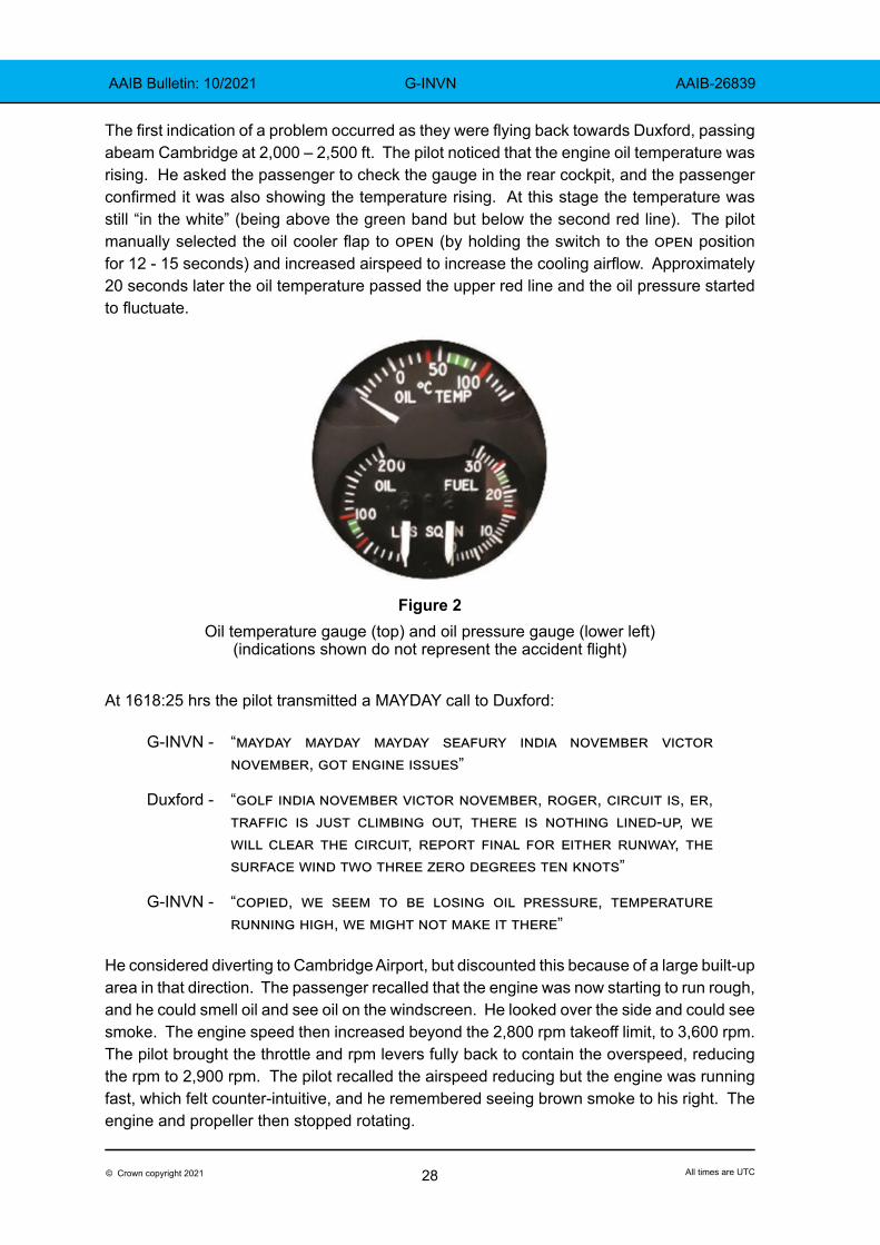
The first indication of a problem occurred as they were flying back towards Duxford, passing abeam Cambridge at 2,000 – 2,500 ft. The pilot noticed that the engine oil temperature was rising. He asked the passenger to check the gauge in the rear cockpit, and the passenger confirmed it was also showing the temperature rising. At this stage the temperature was still “in the white” (being above the green band but below the second red line). The pilot manually selected the oil cooler flap to open (by holding the switch to the open position for 12 - 15 seconds) and increased airspeed to increase the cooling airflow. Approximately 20 seconds later the oil temperature passed the upper red line and the oil pressure started to fluctuate.
Figure 2Oil temperature gauge (top) and oil pressure gauge (lower left)
(indications shown do not represent the accident flight)
At 1618:25 hrs the pilot transmitted a MAYDAY call to Duxford:
G-INVN - “mayday mayday mayday seafury india november victor november, got engine issues”
Duxford - “golf india november victor november, roger, circuit is, er, traffic is just climbing out, there is nothing lined-up, we will clear the circuit, report final for either runway, the surface wind two three zero degrees ten knots”
G-INVN - “copied, we seem to be losing oil pressure, temperature running high, we might not make it there”
He considered diverting to Cambridge Airport, but discounted this because of a large built-up area in that direction. The passenger recalled that the engine was now starting to run rough, and he could smell oil and see oil on the windscreen. He looked over the side and could see smoke. The engine speed then increased beyond the 2,800 rpm takeoff limit, to 3,600 rpm. The pilot brought the throttle and rpm levers fully back to contain the overspeed, reducing the rpm to 2,900 rpm. The pilot recalled the airspeed reducing but the engine was running fast, which felt counter-intuitive, and he remembered seeing brown smoke to his right. The engine and propeller then stopped rotating.

29© Crown copyright 2021 All times are UTC
AAIB Bulletin: 10/2021 G-INVN AAIB-26839
The pilot lowered the aircraft’s nose and found that it required an attitude of approximately 45° nose-down to maintain airspeed. He maintained 135 kt and remembered thinking “just keep it flying”. The aircraft was descending rapidly, which he considered gave him limited options, and his view forward was restricted by oil on the windscreen. He selected a brown field slightly to the right and at 1619:26 hrs transmitted a final call to Duxford:
“just lost the engine, making a forced landing”
He kept the landing gear up as he believed this was the safest option for an off-airfield landing. He selected the flaps down, though unsure if there was enough hydraulic pressure for them to travel. He did not have time to select the fuel or magnetos off nor to open or jettison the canopy. The passenger did briefly consider jettisoning his canopy but thought he did not want to create extra drag.
Nearing the ground, the pilot flared the aircraft to reduce the rate of descent but did not hold it off. The aircraft hit the ground and bounced, then hit again and skidded across the field. The aircraft slid into a tree on the far side of the field, which spun it around, and it came to rest in a hedgerow (Figure 3).
Figure 3G-INVN after the accident
The pilot and passenger were able to climb out and move away from the aircraft. Local residents arrived quickly, and the pilot and passenger told them to stay away from the aircraft as there remained a risk of fire from the fuel on board. Another pilot who was flying nearby and heard the pilot’s transmissions was able to locate the wreckage and pass the location to Duxford. Emergency services from Duxford arrived shortly afterwards.
The pilot and passenger were taken to hospital, both having suffered broken vertebrae.
Witnesses
Several people saw or heard the aircraft in flight. One witness, located north-west of Cambridge, heard it pass over heading north. He tracked the aircraft on Flightradar24 and, when he saw it was coming back overhead, went to look for it. When he heard it

30© Crown copyright 2021 All times are UTC
AAIB Bulletin: 10/2021 G-INVN AAIB-26839
for the second time, he described it as “sounding totally different, clattery, not missing, sounding rough”.
Several people in villages near the accident site reported hearing and seeing the aircraft before the accident. They reported hearing a rough running engine and seeing smoke coming from the aircraft. Several of them heard the engine stop. Video footage and several still photographs supplied to the AAIB showed a smoke trail coming from the aircraft (Figure 4). A witness who was close to the accident site saw the aircraft flying towards him. He described seeing “thick black smoke coming from both sides” and that “the propeller was rotating but then stopped and the nose dropped”.
Figure 4G-INVN in flight just prior to the accident with smoke trail visible
(Photograph used with permission)
Accident site
The aircraft touched down mid-way across a smooth ploughed field travelling in a south-westerly direction and continued until it reached a dense hedgerow with trees (Figure 5). It did not slow significantly, travelling approximately 160 m, with the landing gear raised, over the dry hard earth. After the initial impact there was a second impact impression and thereafter a debris trail of small metallic items, remains of antennas and part of an engine mount.
The left wingtip struck the hedge first and caused the aircraft to rotate anti-clockwise (as viewed from above) whilst travelling along the hedge line. The aircraft came to rest in three pieces: the engine, the forward fuselage with wings, and the rear fuselage. The engine had detached from its mountings during the ground slide but was still attached to the airframe by several large-diameter electrical cables. The fuselage had broken just aft of the front windscreen, which coincided with the rear of the wing structure.

31© Crown copyright 2021 All times are UTC
AAIB Bulletin: 10/2021 G-INVN AAIB-26839
N
Figure 5Accident location
Recorded information
Video footage of the morning flight included the start-up, taxi, takeoff and landing, and showed a smoke trail from the aircraft on takeoff. Several people watched this takeoff and opinion was divided as to whether the smoke trail was normal.
The image in Figure 6 was taken after the flight and showed an oil streak along the left side of the aircraft. The oil streak appeared to emerge from the crankcase breather duct positioned beside the cowling flaps.
Figure 6G-INVN after the first flight showing an oil streak on the left side
(Still photograph taken from video used with permission - Sky High Films)
Further video footage showed the start-up, taxi and takeoff of the accident flight. During the pre-flight checks, smoke could be seen coming from the exhaust for the No 9 cylinder (rear bank, master cylinder) (Figure 7). No smoke was observed coming from any other exhaust. The footage also showed a smoke trail during the takeoff, and there appeared to be more smoke than was visible on the first flight.

32© Crown copyright 2021 All times are UTC
AAIB Bulletin: 10/2021 G-INVN AAIB-26839
Figure 7G-INVN before the accident flight showing smoke from No 9 exhaust
(Still photograph taken from video. Image used with permission)
Aircraft information
G-INVN was a Hawker Sea Fury T.20 two-seat training aircraft originally built in 1951. The aircraft was used in a variety of roles until, in 1990, it suffered an engine failure and forced landing in which it was significantly damaged. It was rebuilt and returned to the UK in 2009. During the winter of 2017/2018 the Bristol Centaurus engine was removed and replaced by a Pratt & Whitney (P&W) R2800-CB3 18-cylinder radial engine. The five-bladed propeller was replaced by a 4 m diameter four-bladed propeller from a Grumman Guardian. The engine had been overhauled in 2016 and had completed 86 flying hours before the accident flight. The aircraft was used for private flights, display flying and recreational flights within the Safety Standards Acknowledgement and Consent framework1.
Engine
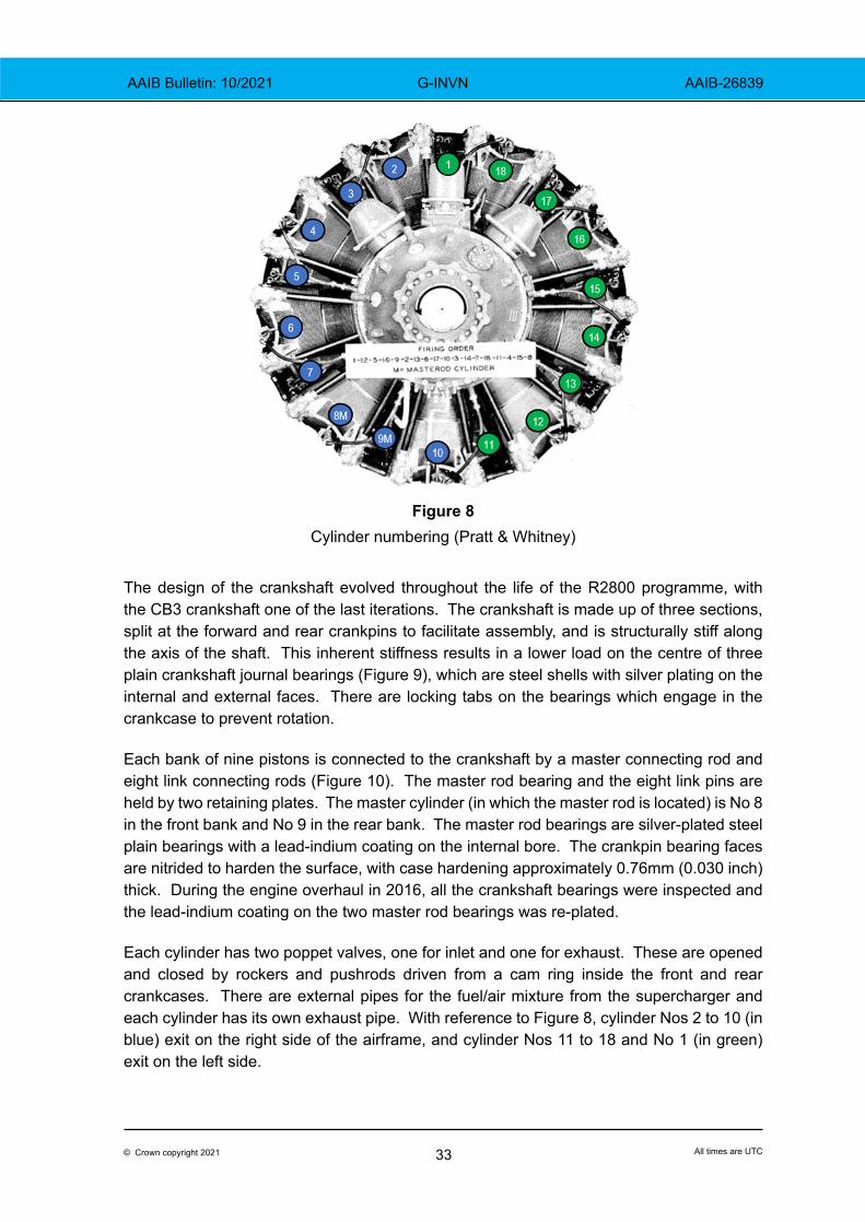
The P&W R2800 engine has two banks of nine cylinders driving a single crankshaft. The crankshaft drives a supercharger to compress the fuel/air mixture from a carburettor mounted on the upper rear crankcase. Aft of the supercharger is an accessory gearbox to which the oil pumps, filters, an electrical generator and a starter motor are attached. The front of the crankshaft drives another accessory gearbox for magnetos, an oil pump and the reduction gearbox for the propeller. The engine has an oil-fed propeller governor to control the pitch of the propeller blades. Cylinder numbering is shown in Figure 8 with the engine viewed from the front.
Footnote1 Safety Standards Acknowledgement and Consent (SSAC) | UK Civil Aviation Authority (caa.co.uk) [accessed
January 2021]. SSAC is a risk analysis framework that allows operators to offer fare-paying recreational flights in certain aircraft that are unable to meet commercial safety standards. An operator intending to offer SSAC flights must ensure that the risks to both participants, third parties and other airspace users have been considered.
33© Crown copyright 2021 All times are UTC
AAIB Bulletin: 10/2021 G-INVN AAIB-26839
Figure 8
Cylinder numbering (Pratt & Whitney)
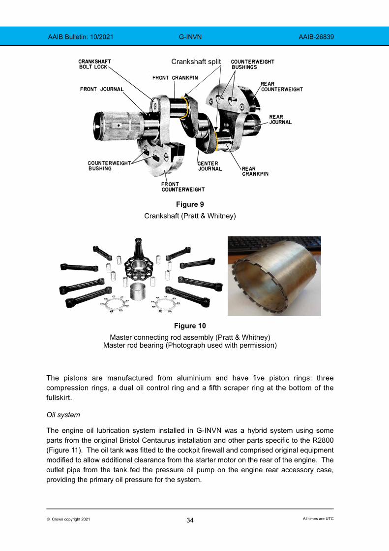
The design of the crankshaft evolved throughout the life of the R2800 programme, with the CB3 crankshaft one of the last iterations. The crankshaft is made up of three sections, split at the forward and rear crankpins to facilitate assembly, and is structurally stiff along the axis of the shaft. This inherent stiffness results in a lower load on the centre of three plain crankshaft journal bearings (Figure 9), which are steel shells with silver plating on the internal and external faces. There are locking tabs on the bearings which engage in the crankcase to prevent rotation.
Each bank of nine pistons is connected to the crankshaft by a master connecting rod and eight link connecting rods (Figure 10). The master rod bearing and the eight link pins are held by two retaining plates. The master cylinder (in which the master rod is located) is No 8 in the front bank and No 9 in the rear bank. The master rod bearings are silver-plated steel plain bearings with a lead-indium coating on the internal bore. The crankpin bearing faces are nitrided to harden the surface, with case hardening approximately 0.76mm (0.030 inch) thick. During the engine overhaul in 2016, all the crankshaft bearings were inspected and the lead-indium coating on the two master rod bearings was re-plated.
Each cylinder has two poppet valves, one for inlet and one for exhaust. These are opened and closed by rockers and pushrods driven from a cam ring inside the front and rear crankcases. There are external pipes for the fuel/air mixture from the supercharger and each cylinder has its own exhaust pipe. With reference to Figure 8, cylinder Nos 2 to 10 (in blue) exit on the right side of the airframe, and cylinder Nos 11 to 18 and No 1 (in green) exit on the left side.
34© Crown copyright 2021 All times are UTC
AAIB Bulletin: 10/2021 G-INVN AAIB-26839
Crankshaft split
Figure 9Crankshaft (Pratt & Whitney)
Figure 10Master connecting rod assembly (Pratt & Whitney)
Master rod bearing (Photograph used with permission)
The pistons are manufactured from aluminium and have five piston rings: three compression rings, a dual oil control ring and a fifth scraper ring at the bottom of the fullskirt.
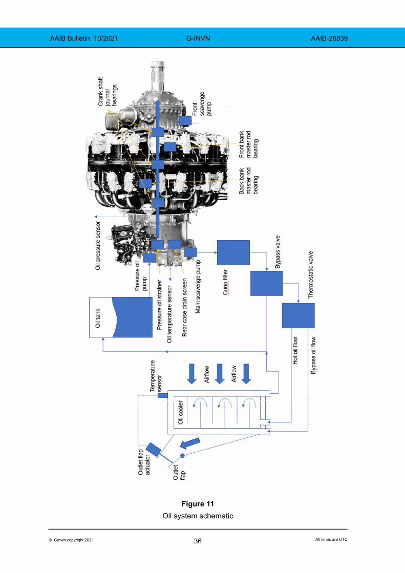
Oil system
The engine oil lubrication system installed in G-INVN was a hybrid system using some parts from the original Bristol Centaurus installation and other parts specific to the R2800 (Figure 11). The oil tank was fitted to the cockpit firewall and comprised original equipment modified to allow additional clearance from the starter motor on the rear of the engine. The outlet pipe from the tank fed the pressure oil pump on the engine rear accessory case, providing the primary oil pressure for the system.
35© Crown copyright 2021 All times are UTC
AAIB Bulletin: 10/2021 G-INVN AAIB-26839
Within the engine, oil from the pressure oil pump passes through the pressure oil strainer and then into seven individual oil pathways to ensure complete lubrication. Oil to the rear crankshaft journal is supplied by a short pipe from a pocket in the centre of the rear crankshaft. Oil passes through the centre of the crankshaft to the front of the engine, lubricating the crankshaft, pistons and master rod bearings. Another pump in the front accessory case boosts the oil pressure to the propeller governor. Oil is returned to the rear of the engine by the front scavenge oil pump and then pumped out of the engine by the main scavenge oil pump. Oil from the rear of the engine passes through the rear case drain screen before joining the scavenge system.
The oil pressure gauge in each cockpit was connected to a common pressure tapping on the rear engine case. The oil temperature gauge in the front cockpit was connected to a sensor in the oil outlet pipe, whereas the rear cockpit gauge was connected to a sensor in the rear accessory case. They were both protected by the same circuit breaker (CB) labelled ‘oil tmp’.
Scavenged oil passed through a metal mesh Cuno2 pressure filter mounted on the engine firewall and then to a bypass valve. The Cuno filter replaced the original suction filter which was installed between the oil tank and the engine. The pressure oil strainer was fitted with a bypass valve which operated if the filter became blocked. The outlet pressure of the scavenge pump was unregulated, so a bypass valve provided over-pressure protection for the oil cooler and was set to open at 100 psi.
Oil cooler system
An oil cooler was installed in the left wing root and used the airflow of forward flight to cool the oil (Figure 12). Air entered the cooler through a slot in the wing leading edge and passed through the cooler core, which was made up of 5.2 mm diameter copper alloy pipes. Heated airflow exited through the lower wing surface and was regulated by a movable flap. A cockpit switch allowed the flap to be manually opened, closed, switched off, or to operate automatically. The switch was sprung to off, in which the flap would remain in its current position, and it was necessary to hold it in either the open or close position to manually adjust the flap. The switch was normally placed in auto. The flap was opened and closed by an electrical actuator and used a temperature sensor in the cooler outlet in the auto mode. The circuit was protected by a CB labelled ‘oil clr’.
Footnote2 A Cuno filter is a cartridge oil filter made up of alternating metal woven mesh disks and spacers. Contamination
is caught on the mesh.
36© Crown copyright 2021 All times are UTC
AAIB Bulletin: 10/2021 G-INVN AAIB-26839
Figure 11Oil system schematic

37© Crown copyright 2021 All times are UTC
AAIB Bulletin: 10/2021 G-INVN AAIB-26839
Figure 12Oil cooler
If the oil temperature was lower than 50°C the thermostatic valve diverted the oil to the bypass inlet of the cooler, where it flowed around the cooler frame and back to the oil tank. The valve would gradually open as the oil temperature rose from 50°C to 95°C, allowing hot oil to flow into the cooler core and over the matrix of copper alloy pipes. The core was made up of ten sections with internal baffles, forcing the oil to travel back and forth across the core sections to maximise contact with the air-cooled pipes. At the end of the core the oil joined the bypass flow in the frame of the cooler and returned to the tank.
Several entries made in the aircraft maintenance log in 2019 referred to the oil cooler leaking. Each entry was closed stating that the cooler had been repaired. During annual maintenance in October 2019 it was noted that the cooler was leaking again. The cooler was removed and sent to a specialist to manufacture new core sections and replace them in the original frame. The cooler was then flushed and pressure tested to ensure integrity prior to completion. The rebuilt cooler was fitted in July 2020.
Crankcase breather
In all piston engines there is some leakage of combustion gases past the piston rings into the crankcase. To allow these gases to escape without damaging the engine there is a ventilation system in the crankcase. The internal volume of the engine, from the propeller reduction gearbox to the supercharger, is interconnected and allows free passage of oil and gases. On the front face of the supercharger diaphragm there are four orifices located on the periphery of the casing which lead through internal passages in the crankcase to two ports on the rear of the crankcase. These ports are connected by pipes to ducts mounted on the side of the engine cowls (Figure 13).

38© Crown copyright 2021 All times are UTC
AAIB Bulletin: 10/2021 G-INVN AAIB-26839
Supercharger diaphragm
Figure 13Crankcase breathers
(Photograph (left) used with permission - Aerotech (Suffolk) Ltd)
Oil priming process
G-INVN had last flown on 28 October 2019, before the maintenance check. The engine was not run again until 3 August 2020 due to the oil cooler replacement. The engine oil was replaced and the filters were cleaned in January 2020. The engine was not inhibited whilst waiting for the new cooler.
Before the engine was started after the maintenance check, the oil which had collected in the engine was drained and an oil priming rig was attached to the oil pressure tapping on the rear case. The oil priming rig was used to heat approximately two gallons of engine oil to 60°C and then pump it into the engine at about 80 psi using an electric pump. This process was intended to ensure that all the bearings were lubricated before the first engine start after being dormant. The priming oil was pumped through the engine and the other system components and added to the oil already in the tank. The propeller was rotated by hand during priming, with one spark plug removed from each cylinder to ensure that no hydraulic lock3 occurred.
No written procedure was available for the operation of the priming rig but the person operating it had been trained by those familiar with it.
After completion of the priming process, the engine was run on the ground to verify system functionality. High power ground runs, the first flight and the accident flight were all made the following day.
Footnote3 Oil can enter the lower (inverted) cylinders of an engine by seepage past seals and piston rings. A hydraulic
lock occurs when the volume of any incompressible fluids in a cylinder approaches the volume remaining as the piston moves towards top dead centre. If the engine is rotated past this point, mechanical failure can occur, usually manifesting as damage to the connecting rods.

39© Crown copyright 2021 All times are UTC
AAIB Bulletin: 10/2021 G-INVN AAIB-26839
Propeller pitch control
Pressurised oil from the front accessory case pump is fed to the propeller governor to control the pitch of the propeller blades and maintain the selected engine rpm. Aerodynamic loads on the blades tend to move them to ‘fine’ pitch to align with the blade rotation. In fine pitch the load on the engine decreases and the speed of the propeller increases. When the blades are rotated to ‘coarse’ pitch their angle of attack increases, increasing the load on the engine and reducing the speed of rotation.
Aircraft examination
Initial inspection
An inspection of the aircraft at the accident site revealed the damage sustained either whilst travelling cross the field or during the impact with the hedge. Two propeller blades were bent backwards and had scratches consistent with scraping across the ploughed field. One blade had detached at the blade root and had failed in bending, and there was evidence of it having struck a substantial tree trunk in the hedge. The engine had become detached from the mounting structure and had pitched nose-down as it travelled across the field. This motion had caused the starter motor to rupture the engine oil tank, so it was not possible to determine the amount of oil remaining in the system before impact. The rear of the engine bay was covered in oil and there was evidence of oil contamination on the ground. The carburettor, generator, one magneto and other engine ancillaries had suffered impact damage during the accident.
The fuselage had split to the rear of the windscreen and the gap between the two sections was approximately one metre. The sheet metal on the left side of the break showed signs of compression buckling and tearing in tension whereas the right side showed only tearing in tension. The cockpit instrument panels were largely intact, but the transponder had become dislodged and was found several metres to the right of the fuselage. All the CBs were closed (in) except the ‘oil clr’ and ‘oil tmp’. There was evidence of oil streaking along the side of the fuselage from each of the crankcase breather ducts (Figure 14).
Figure 14Oil streak from crankcase breather ducts
40© Crown copyright 2021 All times are UTC
AAIB Bulletin: 10/2021 G-INVN AAIB-26839
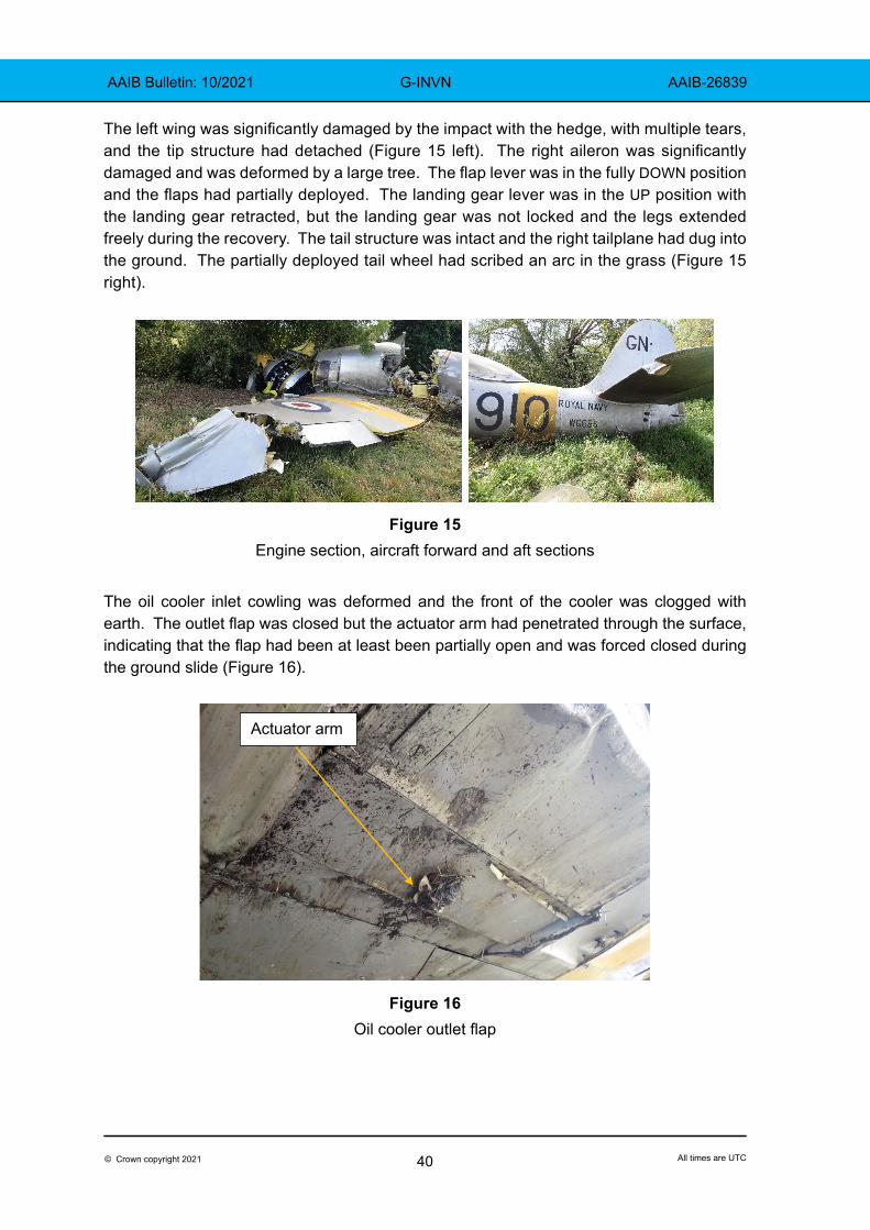
The left wing was significantly damaged by the impact with the hedge, with multiple tears, and the tip structure had detached (Figure 15 left). The right aileron was significantly damaged and was deformed by a large tree. The flap lever was in the fully DOWN position and the flaps had partially deployed. The landing gear lever was in the UP position with the landing gear retracted, but the landing gear was not locked and the legs extended freely during the recovery. The tail structure was intact and the right tailplane had dug into the ground. The partially deployed tail wheel had scribed an arc in the grass (Figure 15 right).
Figure 15Engine section, aircraft forward and aft sections
The oil cooler inlet cowling was deformed and the front of the cooler was clogged with earth. The outlet flap was closed but the actuator arm had penetrated through the surface, indicating that the flap had been at least been partially open and was forced closed during the ground slide (Figure 16).
Actuator arm
Figure 16Oil cooler outlet flap

41© Crown copyright 2021 All times are UTC
AAIB Bulletin: 10/2021 G-INVN AAIB-26839
Preliminary engine strip down
The engine was disassembled under AAIB supervision. Initial inspection showed that no external components were missing from the engine, there were no signs of component failure, it was still seized and all visible external damage had been sustained during the ground slide.
The engine had seized with the No 1 piston (rear bank) at or near top dead centre (TDC). Correspondingly the No 10 piston (front bank) was also at or near TDC. All the rear bank pistons were damaged below the scraper ring groove and the scraper rings were partially lost (Figure 17 left). Around the periphery of the piston crown it was evident that some pistons had struck the top of their cylinders (Figure 17 centre) and there were indentations from the inlet valves in all the piston crowns. The side of all pistons showed evidence of abrasion and the compression rings were entrained in the grooves of the master piston (Figure 17 right).
Figure 17Rear bank piston damage (Piston No 9 shown)
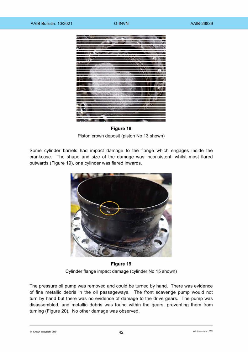
There was considerably less damage to the front bank pistons, with only abrasion damage to the skirts and some pistons retaining metal fragments inside the rear of the piston. There was evidence on some piston crowns, in each bank, of a grey powder deposit (Figure 18). A sample was removed, analysed, and found to contain aluminium, carbon, oxygen, lead and bromine.
42© Crown copyright 2021 All times are UTC
AAIB Bulletin: 10/2021 G-INVN AAIB-26839
Figure 18
Piston crown deposit (piston No 13 shown)
Some cylinder barrels had impact damage to the flange which engages inside the crankcase. The shape and size of the damage was inconsistent: whilst most flared outwards (Figure 19), one cylinder was flared inwards.
Figure 19
Cylinder flange impact damage (cylinder No 15 shown)
The pressure oil pump was removed and could be turned by hand. There was evidence of fine metallic debris in the oil passageways. The front scavenge pump would not turn by hand but there was no evidence of damage to the drive gears. The pump was disassembled, and metallic debris was found within the gears, preventing them from turning (Figure 20). No other damage was observed.

43© Crown copyright 2021 All times are UTC
AAIB Bulletin: 10/2021 G-INVN AAIB-26839
Figure 20
Front oil scavenge pump
The two engine oil filters and the Cuno filter were removed and their contents examined. The metal mesh filters contained a large amount of fine metallic debris whereas the rear case screen contained a quantity of large metallic fragments (Figure 21). These fragments were identified as broken pieces of piston skirt and piston ring. The fine metallic debris was analysed and was found to be silver, iron, aluminium and copper.
Figure 21Left – pressure oil strainer. Right – debris from rear case drain screen
Crankcase strip down
The propeller reduction drive gearbox, front & rear accessory cases and the supercharger were removed from the crankcase. More metallic debris was found inside all sections, similar to that found in the oil filters. None of the components were significantly damaged and all were present and correctly located. On all internal faces the coating of oil was heavily laden with fine metallic particles and there were indications that the oil had reached an abnormally high temperature.

44© Crown copyright 2021 All times are UTC
AAIB Bulletin: 10/2021 G-INVN AAIB-26839
An inspection of the front and rear crankcases revealed evidence that the front and rear crankshaft journal bearings had rotated in the crankcase. The locking tabs of both bearings had dragged in the casing (Figure 22) with the front bearing having rotated approximately three to four degrees. The rotation of the rear bearing was at least 120° as there was continuous mechanical damage between the locking tab slots. It was not possible to determine if the bearing had rotated more than 120°. The bearing surfaces were heavily scored (Figure 23) and there was evidence that the silver had melted and solidified. The centre crankshaft bearing showed no evidence of rotation but some evidence of scoring. The silver bearing material was largely intact.
Figure 22Left – Detail of front bearing rotation (arrowed) and molten metal (circled).
Right – Detail of rear bearing rotation
Figure 23Left – Front crankshaft journal bearingRight – Rear crankshaft journal bearing
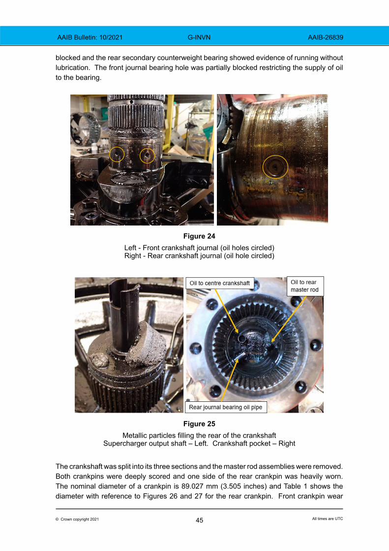
Crankshaft
The crankshaft journals were heavily scored and there was evidence in the journal oil holes of a build-up of fine metallic particles (Figure 24). When the supercharger output shaft was removed from the rear of the crankshaft, the metallic particles retained in the crankshaft pocket were found on the end of the shaft (Figure 25). The oil pipe to the rear bearing was
45© Crown copyright 2021 All times are UTC
AAIB Bulletin: 10/2021 G-INVN AAIB-26839
blocked and the rear secondary counterweight bearing showed evidence of running without lubrication. The front journal bearing hole was partially blocked restricting the supply of oil to the bearing.
Figure 24Left - Front crankshaft journal (oil holes circled)Right - Rear crankshaft journal (oil hole circled)
Figure 25
Metallic particles filling the rear of the crankshaftSupercharger output shaft – Left. Crankshaft pocket – Right
The crankshaft was split into its three sections and the master rod assemblies were removed. Both crankpins were deeply scored and one side of the rear crankpin was heavily worn. The nominal diameter of a crankpin is 89.027 mm (3.505 inches) and Table 1 shows the diameter with reference to Figures 26 and 27 for the rear crankpin. Front crankpin wear
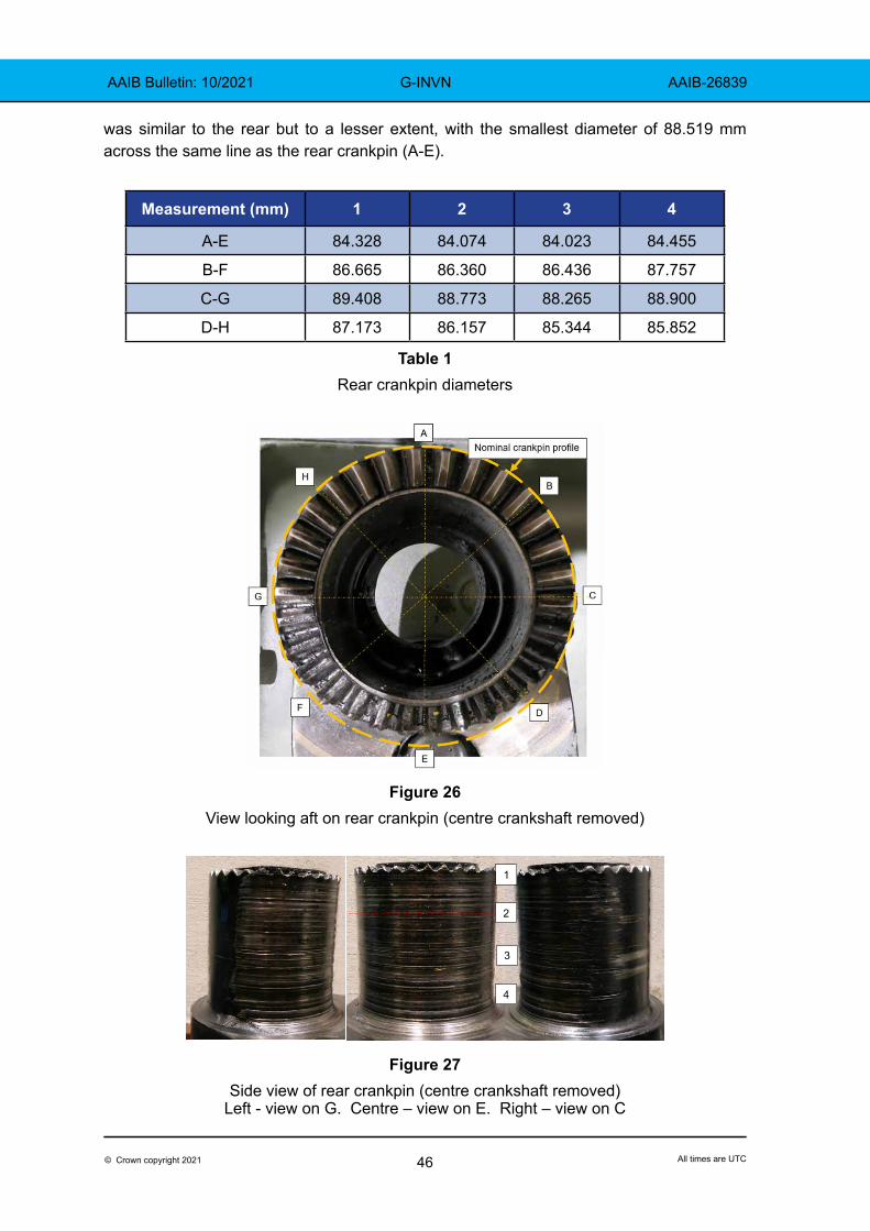
46© Crown copyright 2021 All times are UTC
AAIB Bulletin: 10/2021 G-INVN AAIB-26839
was similar to the rear but to a lesser extent, with the smallest diameter of 88.519 mm across the same line as the rear crankpin (A-E).
Measurement (mm) 1 2 3 4
A-E 84.328 84.074 84.023 84.455
B-F 86.665 86.360 86.436 87.757
C-G 89.408 88.773 88.265 88.900
D-H 87.173 86.157 85.344 85.852
Table 1Rear crankpin diameters
Figure 26View looking aft on rear crankpin (centre crankshaft removed)
1
2
3
4
Figure 27Side view of rear crankpin (centre crankshaft removed)
Left - view on G. Centre – view on E. Right – view on C
47© Crown copyright 2021 All times are UTC
AAIB Bulletin: 10/2021 G-INVN AAIB-26839
Master rods
The front master rod assembly was removed and there was evidence of extensive bearing material erosion and scoring of the bearing face. The bearing faces were wet with heavily contaminated oil indicating that the bearing was being lubricated until the engine stopped.
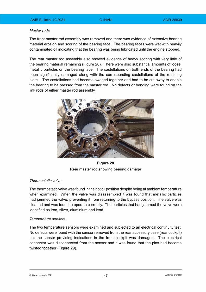
The rear master rod assembly also showed evidence of heavy scoring with very little of the bearing material remaining (Figure 28). There were also substantial amounts of loose, metallic particles on the bearing face. The castellations on both ends of the bearing had been significantly damaged along with the corresponding castellations of the retaining plate. The castellations had become swaged together and had to be cut away to enable the bearing to be pressed from the master rod. No defects or bending were found on the link rods of either master rod assembly.
Figure 28Rear master rod showing bearing damage
Thermostatic valve
The thermostatic valve was found in the hot oil position despite being at ambient temperature when examined. When the valve was disassembled it was found that metallic particles had jammed the valve, preventing it from returning to the bypass position. The valve was cleaned and was found to operate correctly. The particles that had jammed the valve were identified as iron, silver, aluminium and lead.
Temperature sensors
The two temperature sensors were examined and subjected to an electrical continuity test. No defects were found with the sensor removed from the rear accessory case (rear cockpit) but the sensor providing indications in the front cockpit was damaged. The electrical connector was disconnected from the sensor and it was found that the pins had become twisted together (Figure 29).
48© Crown copyright 2021 All times are UTC
AAIB Bulletin: 10/2021 G-INVN AAIB-26839
Figure 29Oil temperature sensor electrical connection pins
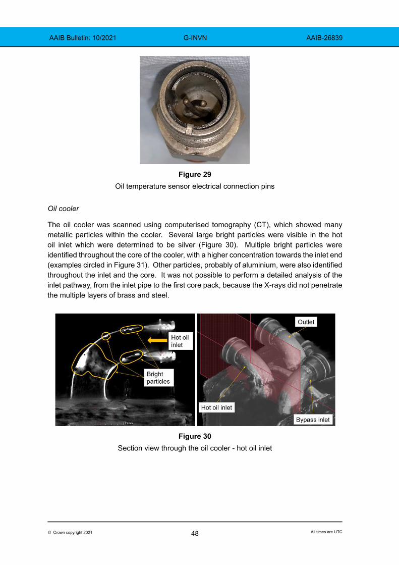
Oil cooler
The oil cooler was scanned using computerised tomography (CT), which showed many metallic particles within the cooler. Several large bright particles were visible in the hot oil inlet which were determined to be silver (Figure 30). Multiple bright particles were identified throughout the core of the cooler, with a higher concentration towards the inlet end (examples circled in Figure 31). Other particles, probably of aluminium, were also identified throughout the inlet and the core. It was not possible to perform a detailed analysis of the inlet pathway, from the inlet pipe to the first core pack, because the X-rays did not penetrate the multiple layers of brass and steel.
Figure 30Section view through the oil cooler - hot oil inlet

49© Crown copyright 2021 All times are UTC
AAIB Bulletin: 10/2021 G-INVN AAIB-26839
Figure 31Oil cooler core. Some particles highlighted
Survivability
Whilst the fuselage had split across the front cockpit, the space the pilot occupied had remained largely intact. The rear cockpit was not disrupted. This left a survivable space for both occupants. The aircraft did not catch fire, despite having approximately 700 litres of fuel onboard, which allowed time for them to escape.
Both occupants were wearing kevlar flying helmets. It is likely these protected them from more serious head injuries.
Meteorology
At 1520 hrs, Cambridge Airport (5 nm north-east of the accident site) reported surface wind from 240° at 11 kt, visibility greater than 10 km, few clouds at 4,800 ft, temperature 22°C, dewpoint 6°C and QNH 1013 hPa.
At 1520 hrs, Stansted Airport (16 nm south south-east of the accident site) reported surface wind from 230° at 12 kt and visibility greater than 10 km. There was no discernible cloud, the temperature was 22°C, dewpoint 7°C and the QNH 1014 hPa.
The weather did not change significantly during the three flights the pilot conducted on the day of the accident.
Pilot background
The pilot held an EASA Air Transport Pilot’s Licence and was a qualified Test Pilot. He was flying the Sea Fury on a valid Single Engine Piston rating. He also held a Flight Instructor rating and an Aerobatic rating. He held a valid Class 1 medical certificate.
He had a total flight experience of 3,508 hours including 31 hours flying G-INVN.
After the accident the pilot reflected on the aspects of his previous experience which he felt had helped him manage the engine failure. He had previously practiced 10 – 15 forced
50© Crown copyright 2021 All times are UTC
AAIB Bulletin: 10/2021 G-INVN AAIB-26839
landings in a Spitfire simulator. Although the simulator was not representative of a Sea Fury, he felt it helped to reduce the startle and stress of the real thing. He reported that it enabled him to focus on flying the aircraft and maintaining airspeed.
Just prior to the accident flight he had flown a display in a North American P51D Mustang to renew his Display Authorisation. Prior to the renewal flight he had discussed with the examiner how to manage engine failures during a display. They considered the priority was maintaining airspeed and that an off-airfield landing may be the safest option even when close to the airfield. They agreed that the key was to arrive at the ground with the wings level and a low rate of descent.
The pilot had also previously experienced engine failures in a Boeing Stearman biplane and in a Saab Safir single engine training aircraft, although these had both occurred over airfields and he had been able to land successfully.
He described how he always took time to think about the aircraft type he was due to fly, to review the operating handbook and to visualise his actions. He also felt that his currency helped: although he had not flown the Sea Fury recently, he had flown a Chance Vought Corsair which has the same engine type.
He commented that he had attended the annual Warbird Symposium at Shuttleworth House in February 2020 which included lectures on engineering, operations, human factors and lessons learnt from display flying. He felt this refreshed his knowledge and helped him think clearly as the emergency unfolded.
Organisational information
The accident flight was a private flight. The operator provided a copy of the Organisational Control Manual (OCM) under which the aircraft was being operated (in accordance with CAP 6324) and a copy of the Pilot’s Notes for G-INVN.
The only guidance relating to engine failure in the pilots notes stated:
‘A power off landing should NOT normally be made with full flap as the flight path with gear down and full flaps is very steep and the rate of descent is very high. The recommended technique is to lower the flaps to the takeoff position whilst maintaining 130 kt. When landing is assured the flaps should be lowered to the max lift position and a gradual round-out should be performed to change the attitude and flight path angle, and to arrive at the threshold at 115 kt. There is little increase in the landing roll between max lift and down flaps. A flapless glide-speed of 150 kt is recommended until landing is assured.’
Footnote4 CAP632 – ‘Operation of “Permit-to-Fly” ex-military aircraft on the UK register’. This document specifies
the operational requirements that an applicant for the issue of a Permit-to-Fly for an ex-military aircraft is required to meet.
51© Crown copyright 2021 All times are UTC
AAIB Bulletin: 10/2021 G-INVN AAIB-26839
Other information
Propeller driving the engine – manifold pressure insufficient for selected engine speed
In a radial engine, as the crankshaft rotates in normal operation, the resultant force from the power stroke of each piston and the centrifugal load, is directed at the same spot on the crankpin via the master rod assembly. The location of the oil supply hole in the crankpin is optimised to ensure an effective oil film lubricates the master rod bearing in normal operation.
The oil flow is turbulent as it enters the clearance between the crankpin and the bearing, and therefore is not an effective lubricating film. Consequently, the oil hole is positioned such that the oil has become a uniform laminar film as it reaches the highly loaded bearing faces (the precise location having been established empirically by the manufacturer as it developed the engine).
If, because of insufficient gas load (manifold pressure), the propeller is allowed to drive the engine, the resultant force on the crankshaft is applied to the opposite side of the crankpin, where the oil supply is not optimised, and may quickly damage the bearing. This damage worsens over time and eventually the bearing will fail. Failure may occur several hours after the initiating event, and therefore a pilot may inadvertently damage the bearing without seeing any immediate symptoms requiring maintenance intervention. The engine is designed to cope with some reverse loading for brief periods, for example when the propeller is driven at lower airspeed when landing, but critical damage may occur quickly at higher speeds.
An Engine Operating Information Letter published by Pratt & Whitney in January 19525, describes how low manifold pressure with high rpm can lead to the propeller driving the engine and cause bearing damage. The letter recommends ensuring at least one inch of manifold pressure be used for each 100 rpm (so that for example at 2,200 rpm, 22 inches is the minimum manifold pressure).
This feature of radial engines was discussed with the accident pilot. He was familiar with the issue and reported that he always operated the engine to avoid low manifold pressure with high rpm. Whilst it was necessary to close the throttle to land, at this stage the airspeed was relatively low, and at high speed he would ensure the manifold pressure was greater than the rpm/100. When flying the stall manoeuvres, he reported that he flew a gentle climb to avoid needing to select idle power.
After speaking to the accident pilot, the AAIB interviewed all the pilots who had flown G-INVN for the previous 20 flights (back to 26 August 2019). All reported they were familiar with the hazards of operating at insufficient manifold pressure and reported that they operated the engine to keep manifold pressure above rpm.
Footnote5 Pratt & Whitney Manual of Engine Operation – Engine Operation Information Letter Number 25,
22 January 1952.

52© Crown copyright 2021 All times are UTC
AAIB Bulletin: 10/2021 G-INVN AAIB-26839
Other pilot’s reports
The only problem reported by these other pilots was the oil leaks from the oil cooler. They reported that the oil temperature was never a problem in flight. Once the engine had warmed up, the oil temperature remained constant. They all reported that they left the oil cooler switch in auto in flight. A few pilots selected the switch to open after landing if they had a long taxi and the weather was warm. Off-airfield landing
The pilot reported that when the engine failed, he did not consider abandoning the aircraft. He had briefed the passenger that if the engine failed whilst away from the aerodrome he would attempt to land in a suitable field. When the engine did fail, he still considered this to be the safest option. Reflecting after the accident he was confident that this was the correct decision. He felt that, given the low altitude and the high rate of descent required to maintain airspeed, there was not enough time for them both to abandon the aircraft safely.
There was no procedure for an off-airfield landing in the pilot notes provided by the operator. However, based on his experience the pilot considered a gear-up landing was the safest option. He believed this would minimise drag in the descent, reduce the risk of the aircraft tipping over on landing and remove the risk of only one gear extending with limited hydraulic pressure. Figure 32 is an extract from the pilot notes published by the Royal Navy for the Sea Fury Mk 10 & 116.
Figure 32Extract from the Sea Fury Mk 10 & 11 pilot notes
6 A.P. 4018A & B -P.N. Sea Fury Mk 10 & 11 Pilot Notes, 2nd Edition, May 1950.

53© Crown copyright 2021 All times are UTC
AAIB Bulletin: 10/2021 G-INVN AAIB-26839
Passenger briefing
The OCM required passengers to be briefed on seatbelt operation, canopy hood operation, communication equipment, forced landing procedure, in-flight emergencies, bail out procedure and aircraft hazard areas. The passenger reported that he received a thorough briefing in all these areas before the flight. He recalled that he and the pilot discussed the procedures for making an off-airfield landing and for abandoning the aircraft. They briefed that they would make an off-airfield landing if the engine failed and it was not possible to reach an airfield, and that they might need to abandon the aircraft in the event of a fire or after a mid-air collision if the aircraft was uncontrollable.
Chip detectors
To assist in the early detection of failures some engine and gearbox systems are equipped with magnetic chip detectors, in which magnetic plugs are installed at strategic locations within the oil system to attract ferrous material. In systems that provide an indication in the cockpit, when enough metal has built up on the plug it forms a bridge across an electrical connector and illuminates a warning light to alert the pilot. In other systems it is necessary to remove the plug to inspect for any build-up of particles on the magnet.
A major operator of R2800 engines has used such a system successfully to provide early warning of significant damage, enabling remedial action before catastrophic failure.
Corrosion in inactive engines
Corrosion is a possibility in engines during any extended period of inactivity, and inhibiting procedures are intended to address this. UK operator experience indicates that large radial engines that are inactive for several months without inhibiting do not necessarily suffer catastrophic failure.7
Analysis
Accident flight indications
The first abnormal indication reported by the pilot was the increase in oil temperature. The oil temperature continued to rise and, soon after, the oil pressure was seen to fluctuate. The increase in oil temperature was caused by the oil encountering increased heat energy from multiple sources and a reduction in the effectivity of the oil cooler.
Video footage of the engine run-up before the accident flight showed smoke emerging from the rear bank master cylinder (No 9) but not from any other exhaust. As the engine had been run for several minutes it is likely that any residual oil in the cylinders would have been burnt off or blown from the exhausts by that time. The No 9 piston exhibited substantial wear on the leading face of the piston (relative to engine rotation) and some of the piston rings were entrained into the piston ring grooves. This would have allowed oil to pass into the combustion chamber, generating the observed smoke, and would have allowed
Footnote7 UK operator of up to eight R2800-CB3 engines in low utilisation between 2004 and 2008, involving inactive
winters of approximately seven months, following which there were no reported operating issues.
54© Crown copyright 2021 All times are UTC
AAIB Bulletin: 10/2021 G-INVN AAIB-26839
combustion gases into the crankcase. These gases would have elevated the temperature inside the crankcase and some of this additional heat energy would have been absorbed by the engine oil.
The abnormal wear of the master piston was a result of the change in geometry between the master rod, crankshaft and master piston. The relationship between the crankshaft and the master rod is determined by the master rod bearing, so this change in geometry would indicate bearing wear.
The metal particles liberated from the rear bank master rod bearing passed around the engine oil system and contaminated the entire engine, increasing friction and generating more heat in all moving components. All the oil filters were heavily contaminated with metal particles and from the CT scan it was evident that some material had also been captured within the oil cooler core. The multiple path arrangement of the cooler enabled oil to continue following through it but as the pathways became blocked, reducing the surface area available to transfer heat from the oil to the cooling air, its ability to remove heat from the oil system would have diminished. As the heat energy in the system continued to increase, the breakdown of the highly loaded main engine bearings accelerated, further contaminating the oil system.
Eventually the contamination was sufficient to block the oil filters, the filter bypass valves opened, and heavily contaminated oil entered the branches of the oil system. Some of the smaller oil passages (for example to the rear crankshaft journal bearing) were found completely blocked and it is likely that the fluctuations in indicated oil pressure were due to the gauge pressure line being intermittently blocked with metal particles.
The pilot reported that, shortly after he saw the abnormal oil indications, the engine began to run roughly with a significant amount of smoke, and oil covered the cockpit canopy. No damage, such as holes in the crankcase, was found that would have resulted in oil being lost from the engine. There was evidence on the side of the fuselage (Figure 6) that oil was passing out through crankcase breathers. This indicates an increase in crankcase internal pressure, probably caused by pressurised cylinder gases escaping via piston erosion. It is also likely that oil was escaping past the piston rings, in sufficient quantity not to be fully burnt, and then through the exhausts. Both mechanisms would have resulted in smoke and oil being seen by the occupants.
The pilot reported that the engine over sped just before it seized. It is likely that the contamination of the oil system reduced oil pressure to the propeller governor, making it unable to maintain the appropriate blade pitch. The aerodynamic loads on the blades drove them to fine pitch, resulting in an increase in engine speed.
Engine observations
To reduce the engine speed the pilot retarded the throttle and rpm levers, resulting in reduced load on the engine bearings. By this time, it is likely that the silver bearing metal in the front and rear crankshaft bearings was molten, and when the load was reduced this was sufficient for the bearings to solidify and seize the engine. This was evident in rotation of

55© Crown copyright 2021 All times are UTC
AAIB Bulletin: 10/2021 G-INVN AAIB-26839
the journal bearings in the crankcase. The lack of damage exhibited by the centre bearing is probably due to its lower loading.
The silver bearing metal of the rear bank master rod bearing was eroded and the steel bearing shell was running against the crankpin. Load, and therefore wear, is distributed over the full surface of the bearing shell due to the rotation of the master rod relative to the crankpin. However, the same segment of the crankpin always reacts the power stroke and therefore the wear was concentrated on this part of the crankpin. The nitriding slowed this wear but once the case-hardened layer had been worn away, the damage increased rapidly. This was evident in the shape of the rear crankpin when it was inspected after the accident, with approximately 5 mm being lost from the diameter of the crankpin. This material was liberated into the oil system and caused further damage.
As the diameter of the crankpin reduced, the gap into which the oil exited increased from 0.13 mm (0.005 inch) to approximately 5.1 mm (0.200 inch) and would have allowed more oil into the bearing area. This would have disrupted the oil flow to the rest of the engine because the release of oil into the bearing cavities is carefully balanced throughout the engine. This might also have contributed to the oil pressure fluctuations reported by the pilot.
The deterioration of the master rod bearing resulted in a reduction in the clearance between the piston bottom dead centre position and the crankshaft counterweight. As the crankshaft rotated the counterweight struck the lower edge of the piston skirt, removing pieces of it, and broke the oil scraper rings. These pieces of aluminium piston and steel scraper ring were then unrestrained within the crankcase and caused impact damage to the casing. The irregular shape and inconsistent position of the damage to the cylinder flanges inside the crankcase was probably caused by these pieces being caught between the rotating counterweight and the flange. There was no evidence of the counterweight striking the cylinder flange directly. The broken pieces of piston and ring were transported throughout the engine by the oil system and contributed further to the blocking of the oil system passageways.
There was evidence, on the crowns of the rear bank pistons, of impact with the top of the cylinder and the inlet valve. The valve stems were not bent and the depth of the indentation indicated low impact forces, suggesting the impact occurred as the inlet valve opened and the piston was descending into the cylinder, thereby applying insufficient force to the stem to bend it. Wear to the master rod bearing probably allowed the pistons to overtravel at TDC and strike the top of the cylinder, as indicated by the ring around the periphery of the piston crown. There was a fine powder residue on some of the piston crowns, which was made up of carbon, lead, aluminium and bromine. The aluminium was probably carried into the combustion chamber in the oil and left behind as the oil was burnt off. The other components were typical residues from the combustion of aviation fuel.
Other observations
When the thermostatic valve was inspected it was found seized in the fully hot position. This indicates that, at the time the engine seized, oil would have been passing through the oil cooler core, but the valve was jammed with metal particles and so had not closed to the bypass position as the thermostruts returned to ambient temperature. The distribution of
56© Crown copyright 2021 All times are UTC
AAIB Bulletin: 10/2021 G-INVN AAIB-26839
metallic particles throughout the oil cooler indicated that contaminated oil had been flowing through the core. The concentration of particles was greatest towards the inlet, indicating that particle-laden oil was flowing into the cooler, with some being entrained within the core, but that some particles were still suspended in the oil all the way to the outlet. This indicates that the oil cooler was contaminated by large amounts of material released from damage elsewhere in the engine. There was no evidence the oil cooler was itself a source of foreign material that could have caused damage to the master rod bearing. It was not possible to determine the amount of metal particles in the oil outlet flow from the cooler because the oil tank, to which the oil passed next, was destroyed during the accident.
The oil tmp and oil clr CBs were found open. The pilot reported he had opened the oil cooler flap to reduce the oil temperature. Inspection at the accident site showed that the oil cooler flap had been open but was forced closed by the ground slide. The investigation could not determine why the oil clr CB had opened.
It is likely both oil temperature gauges were working because the pilot and passenger both reported seeing the same rise in temperature as the engine started to fail. Each cockpit gauge is connected to a separate sensor; one in the oil outlet and one in the rear accessory case. The electrical connector to the oil outlet sensor had rotated, twisting the pins together and causing an electrical short circuit. This would have opened the oil tmp CB.
In the video footage of G-INVN departing for the first flight, no smoke was visible from the exhausts once the initial start-up had cleared the cylinders. When the aircraft returned from the flight there was an oil streak along the left side of the aircraft and smoke could be seen from the right bank of exhausts (due to the camera angle it was not possible to determine which exhaust). The investigation did not determine the cause of the oil streak, which may have come from either the left side crankcase breather or a left side exhaust. Video of the accident flight departure showed the rear bank master cylinder (No 9) exhaust smoking after all the cylinders had cleared following engine start. When the master rod bearing is worn the geometry of the master rod / link rod assembly results in a side load on the master rod, which causes the master piston to become eroded, and it is possible that this smoke indicated the master rod bearing had started to wear and oil was entering the combustion chamber.
Master rod bearing failure
It is likely that the initial mechanical failure was breakdown of the rear bank master rod bearing. Due to the extent of the damage and the amount of debris in the engine it was not possible to determine precisely what initiated the bearing failure. In the following section various possible mechanisms are discussed along with their probability and counter evidence.
Manifold pressure
Radial engines are particularly susceptible to master rod bearing damage during prolonged flight with manifold pressure insufficient to compensate for the reciprocating loads. The pilots who had flown G-INVN since the installation of the R2800 engine reported they

57© Crown copyright 2021 All times are UTC
AAIB Bulletin: 10/2021 G-INVN AAIB-26839
were aware of this issue and stated that they operated the aircraft in a manner intended to avoid it.
Air lock in the oil system
G-INVN was in maintenance for approximately nine months during which there were no engine runs. Engine oil would have settled in the lowest parts of the engine and in some cases oil passageways would have emptied. It is possible for an air lock to have formed during the hot oil priming procedure prior to restart, resulting in a loss of lubrication when the engine was started. However, the oil path from the pressure pump to the rear bank master rod bearing is straight through the crank shaft and it is unlikely it would have been starved of oil long enough to cause significant damage. The hot oil priming process that the maintenance organisation reported it had completed was consistent with the manufacturer’s process and with industry practice. Air locks in the oil system are not considered typical of the R2800.
Hydraulic damage
Oil will drain into the lowest, inverted cylinders of a radial engine when it is stationary and must be purged before engine start to avoid damage. Oil can leak past the valve guides and piston rings into the combustion chambers. If there is enough to create a hydraulic lock, it will result in bending of the link or master rods. This damage will change the way the loads are applied to the master rod bearing and in time may cause bearing failure.
The maintenance organisation reported that during the oil priming process one spark plug was removed from each cylinder and the engine was rotated by hand-turning the propeller. Oil that had collected was either drained from the spark plug hole, or it was pushed into the exhaust system.
One operator of Sea Furys with Pratt and Whitney radial engines described to the AAIB the use of ‘burp plugs’ during oil priming to mitigate the risk of hydraulic lock. The burp plug is a one-way valve which replaces one spark plug per cylinder during the oil priming process. The burp plug allows oil to be ejected from the cylinder but ensures that air is drawn in through the inlet manifold rather than through the open spark plug hole. This results in any residual oil in the inlet manifold being drawn into the cylinder and removed, reducing the opportunity for residual oil to be drawn into the cylinder during engine starting.
During normal operation the engine is rotated until all cylinders have passed through TDC, before switching on the magnetos, to ensure that none of the cylinders is hydraulically locked when the engine starts. This can be achieved by hand rotating the propeller or by using the starter motor. It is usually preferable to turn the engine using the starter motor if it is fitted with a clutch because, should there be a hydraulic lock, the drive will slip before link or master rod damage can occur. In some engine installations, the leverage of a propeller blade, and the multiplying effect of any reduction gearbox, may provide sufficient mechanical advantage to cause damage if the engine is turned by hand.
There was no evidence of damage caused by hydraulic lock, excluding this as a likely cause of master rod bearing failure.

58© Crown copyright 2021 All times are UTC
AAIB Bulletin: 10/2021 G-INVN AAIB-26839
Contamination of the oil system
During the engine’s overhaul before installation into G-INVN, all critical components were inspected and either repaired or replaced with serviceable items. Organisations familiar with the R2800 indicated that significant defects usually become apparent within 5 -10 hours of operation after overhaul. Should an engine pass this threshold without issue it will usually, with appropriate maintenance and correct operation, continue for many hundreds of hours.
The engine in G-INVN failed after 86 flying hours and some unrecorded ground running, past the point where overhaul-related issues might usually be identified. During maintenance prior to the accident flight, the engine was serviced and repairs made to the oil system. The engine oil was replaced and the filters cleaned as part of routine maintenance, and it was recorded that the oil cooler was leaking again. Several entries in the maintenance logbook indicated previous oil cooler repairs had been attempted, but ultimately it was decided to rebuild the cooler. The manufacture of a new cooler took approximately nine months and during this time the aircraft was dormant in the hangar.
The new oil cooler, utilising the original frame and new cores, was flushed and pressure tested upon completion. It is possible that debris remained in the multiple pathways within the cooler and became dislodged in flight on 4 August; or that foreign material entered the oil system during the oil replacement, filter cleaning, oil priming, or oil top-up after the first flight. It is also possible that some corrosion may have formed inside the engine because it was not inhibited during the oil cooler maintenance, and that this corrosion could have detached from the parent material and reached the bearing, causing damage. However, relevant operator experience indicates that this is not necessarily a factor in engines that are inactive for a few months. Likewise, the engine from G-INVN has not exhibited any corrosion during the investigation. The available evidence was not sufficient to determine which, if any of these, was a factor.
The first highly loaded bearing in the oil system is the rear bank master rod bearing, which therefore makes it the most likely to be affected by contamination entering the engine from the cooler or tank. Analysis of the oil and the material found in the filter elements revealed aluminium, silver, lead, indium and iron, all of which are materials used in the engine. The engine damage found would have resulted in all those materials being in the oil.
Given the amount of debris present it was not possible to isolate any foreign material that could be confirmed as initiating the damage to the rear bank master rod bearing. The oil tank was damaged by the starter motor during the accident, which resulted in most of the oil being lost, and some oil was lost through the crankcase breathers or burnt during the flight.
The organisation most familiar with the overhaul of R2800 engines considered that the damage found was consistent with contamination of the oil system.

59© Crown copyright 2021 All times are UTC
AAIB Bulletin: 10/2021 G-INVN AAIB-26839
Possible cause summary
Table 2 summarises the six possible causes of bearing damage identified by the investigation, and the counter evidence if any.
Based on this information the investigation found that oil contamination of some sort was the most likely cause of the initial damage to the rear master rod bearing. It was not possible to determine when this might have occurred.
Chip detectors and oil analysis
A magnetic chip detector might have detected the ferrous material produced by wear to the bearing and crankshaft and found in oil recovered from G-INVN. It is possible that a suitable system would have alerted the pilot during the first flight that maintenance intervention was required, thereby avoiding the accident flight.
Periodic analysis of oil samples can also provide an early indication of damage or excessive wear. This is most effective when conducted over many hundreds of hours and on several engines to establish trends, because it is not unusual for engine oil to contain some metallic particles in normal operation. The engine in G-INVN had run for only 86 hours since overhaul, which may have been insufficient to establish a significant trend.
Possible cause Counter evidence
Insufficient manifold pressure for engine rpm.
All pilots reported that they operated the engine to avoid insufficient manifold pressure for engine rpm.
Air lock in the oil system. Not typical for an R2800. Can affect other large radial engine types.
Hydraulic damage.No damage to the connecting rods. All the
cylinders were drained of oil during oil priming procedure and before engine starting.
Inadequate oil priming. Procedure applied in accordance with normal practice.
Bearing quality issue related to engine overhaul.
Damage normally occurs sooner after overhaul. Engine had operated for 86 hours since overhaul.
Contamination of the oil system. None.
Table 2
Summary of possible causes of rear master rod bearing damage
60© Crown copyright 2021 All times are UTC
AAIB Bulletin: 10/2021 G-INVN AAIB-26839
Pilot’s actions
The first cockpit indication of an engine problem was an increase in oil temperature, which the pilot reported was normally very stable. The pilot’s notes did not contain a procedure for high oil temperature. Based on his experience, the pilot opened the oil cooler manually and increased airspeed to increase cooling airflow, but the temperature continued to rise and the pressure started to fluctuate.
When the engine seized the pilot had the option to abandon the aircraft or to make an off-airfield landing. He reported that he had planned and briefed that, if the engine failed, he intended to make an off-airfield landing. When the engine did fail, he did not consider abandoning the aircraft and focused on landing as planned. With time to reflect after the accident he remained of the opinion that, given the low altitude and high rate of descent, attempting a landing was the safest option.
The pilot reported that, after the engine stopped, he focused on maintaining airspeed and keeping the aircraft flying. Although the pilot’s notes used by the operator did not contain specific guidance on off-airfield landings, based on his experience he kept the landing gear retracted. This was consistent with the guidance in the Royal Navy Sea Fury Mk 10 & 11 pilot’s notes. The high rate of descent limited the choice of fields. He tried to extend the flaps but with little hydraulic pressure they only moved slightly from the up position.
The pilot was able to transmit a mayday call which enabled the emergency services, with the assistance of other aircraft in the area, to locate the aircraft quickly. He did not have time to jettison the canopy or switch off the fuel or ignition before landing.
The AAIB has investigated several single engine aircraft accidents in which the engine failed and the pilot lost control of the aircraft before reaching the ground, often resulting in serious or fatal injury. In this accident the pilot was able to maintain control until reaching the ground, preventing more serious injuries to the occupants. The pilot reported that, before flying, he always took time to mentally rehearse his actions in the event of an emergency. He believed this was of considerable assistance when the engine failed, and that his recent simulator training, general flying recency and past experience all helped him manage the situation successfully.
Conclusion
The engine failure was caused by breakdown of the rear master rod bearing. The release of material and increased friction overwhelmed the oil cooling system and exceeded its capacity to maintain normal operating temperatures, resulting in catastrophic damage to the reciprocating components and eventually engine seizure.
Symptoms of the bearing failure were visible before the accident flight, in the form of abnormal oil smoke, and might have been shown by a chip detector had one been fitted. However, from the moment excessive oil temperature was indicated, total engine failure could not be prevented.
61© Crown copyright 2021 All times are UTC
AAIB Bulletin: 10/2021 G-INVN AAIB-26839
The investigation did not discover precisely what initiated the bearing damage but determined that oil contamination was the most likely cause.
The pilot’s experience, including practice engine failures in a relevant simulator, assisted him in conducting a safe forced landing. Maintaining sufficient airspeed, whilst avoiding built-up areas and the temptation to reach an aerodrome, contributed to this outcome. The accident demonstrates the importance of an effective emergency briefing before flight, and the value of wearing appropriate head protection.
AAIB comment
The investigation has not identified the need for new safety recommendations, but highlights three areas for additional consideration by operators of similar aircraft:
1. An engine oil chip detector may provide sufficient early warning of engine damage to indicate the need for remedial maintenance before further flight.
2. Forced landing or abandonment involves significant risk of injury in high performance aircraft. Operators and pilots can promote safe outcomes by providing clear safety briefings and ensuring all occupants wear effective head protection, as in this case.
3. Training in a relevant simulator can help familiarise pilots with prioritising the tasks necessary to conduct a safe forced landing, including the importance of maintaining sufficient airspeed, field selection, and the passenger and other emergency procedures that must be completed. The AAIB recognises that there are few such simulators for high performance piston driven aircraft, and alternative means of achieving the same training aims may also be beneficial.
Published: 16 September 2021.