AAIA Image Best Practices Sept 22-05 - Advance Auto Parts Imagin… · Best Practices Guideline vs....
35
Imaging Workgroup: Automotive Aftermarket: Imaging Best Practices Workgroup Members: Bob Castle: Global Accessories Bob Rogers: Advance Auto Parts Bruce Cadwell: Affinia Group Chris Gardner: MISG Cliff Birchmeier: Delphi Dan Burtchett: O’Reilly Auto Parts Dan Saunders: Advance Auto Parts David P. Ortega: CSK Auto Debbie Miller: Gates Donna Beluska: Beluska Graphics Ed Heon: Comergent Ed Wolff: ARI Parts Ian McNabb: Pricedex Jerry Hoffmann: NAPA Jeri Jorgenson: 3M Joann Rupp: AutoZone Joe Register: Prescient Technologies Mike Williams: O’Reilly Auto Parts Mark Hickman: Advance Auto Parts Mike Ballard: O’Reilly Auto Parts Ray Nicholas: Four Seasons Pat Weilmeier: Solenium Group Peter Kuhn: Delphi Rachel Thompson: Delco Remy Robert Morris: AAIA Ryan Vernon: DCI Scott Luckett: AAIA Ted Kelley: Activant Terri Gibson: Beluska Graphics Wendy Hughes: O’Reilly Auto Parts
Transcript of AAIA Image Best Practices Sept 22-05 - Advance Auto Parts Imagin… · Best Practices Guideline vs....

Imaging Workgroup: Automotive Aftermarket: Imaging Best Practices
Workgroup Members:
Bob Castle: Global Accessories Bob Rogers: Advance Auto Parts Bruce Cadwell: Affinia Group Chris Gardner: MISG Cliff Birchmeier: Delphi Dan Burtchett: O’Reilly Auto Parts Dan Saunders: Advance Auto Parts David P. Ortega: CSK Auto Debbie Miller: Gates Donna Beluska: Beluska Graphics Ed Heon: Comergent Ed Wolff: ARI Parts Ian McNabb: Pricedex Jerry Hoffmann: NAPA Jeri Jorgenson: 3M Joann Rupp: AutoZone Joe Register: Prescient Technologies Mike Williams: O’Reilly Auto Parts Mark Hickman: Advance Auto Parts Mike Ballard: O’Reilly Auto Parts Ray Nicholas: Four Seasons Pat Weilmeier: Solenium Group Peter Kuhn: Delphi Rachel Thompson: Delco Remy Robert Morris: AAIA Ryan Vernon: DCI Scott Luckett: AAIA Ted Kelley: Activant Terri Gibson: Beluska Graphics Wendy Hughes: O’Reilly Auto Parts
- Section I - 9/22/2005
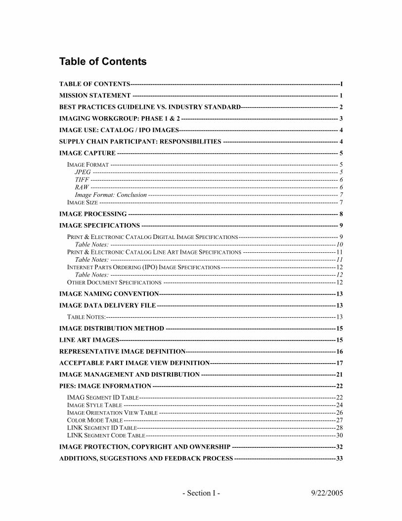
Table of Contents
TABLE OF CONTENTS-----------------------------------------------------------------------------------------------I MISSION STATEMENT --------------------------------------------------------------------------------------------- 1 BEST PRACTICES GUIDELINE VS. INDUSTRY STANDARD-------------------------------------------- 2 IMAGING WORKGROUP: PHASE 1 & 2 ----------------------------------------------------------------------- 3 IMAGE USE: CATALOG / IPO IMAGES------------------------------------------------------------------------ 4 SUPPLY CHAIN PARTICIPANT: RESPONSIBILITIES ---------------------------------------------------- 4 IMAGE CAPTURE ---------------------------------------------------------------------------------------------------- 5
IMAGE FORMAT ------------------------------------------------------------------------------------------------------- 5 JPEG --------------------------------------------------------------------------------------------------------------- 5 TIFF ---------------------------------------------------------------------------------------------------------------- 6 RAW ---------------------------------------------------------------------------------------------------------------- 6 Image Format: Conclusion -------------------------------------------------------------------------------------- 7
IMAGE SIZE ------------------------------------------------------------------------------------------------------------ 7 IMAGE PROCESSING ----------------------------------------------------------------------------------------------- 8 IMAGE SPECIFICATIONS ----------------------------------------------------------------------------------------- 9
PRINT & ELECTRONIC CATALOG DIGITAL IMAGE SPECIFICATIONS--------------------------------------------- 9 Table Notes: ------------------------------------------------------------------------------------------------------10
PRINT & ELECTRONIC CATALOG LINE ART IMAGE SPECIFICATIONS ------------------------------------------11 Table Notes: ------------------------------------------------------------------------------------------------------11
INTERNET PARTS ORDERING (IPO) IMAGE SPECIFICATIONS ----------------------------------------------------12 Table Notes: ------------------------------------------------------------------------------------------------------12
OTHER DOCUMENT SPECIFICATIONS ------------------------------------------------------------------------------12 IMAGE NAMING CONVENTION--------------------------------------------------------------------------------13 IMAGE DATA DELIVERY FILE ---------------------------------------------------------------------------------13
TABLE NOTES:--------------------------------------------------------------------------------------------------------13 IMAGE DISTRIBUTION METHOD -----------------------------------------------------------------------------15 LINE ART IMAGES--------------------------------------------------------------------------------------------------15 REPRESENTATIVE IMAGE DEFINITION--------------------------------------------------------------------16 ACCEPTABLE PART IMAGE VIEW DEFINITION---------------------------------------------------------17 IMAGE MANAGEMENT AND DISTRIBUTION -------------------------------------------------------------21 PIES: IMAGE INFORMATION -----------------------------------------------------------------------------------22
IMAG SEGMENT ID TABLE-----------------------------------------------------------------------------------------22 IMAGE STYLE TABLE ------------------------------------------------------------------------------------------------24 IMAGE ORIENTATION VIEW TABLE --------------------------------------------------------------------------------26 COLOR MODE TABLE ------------------------------------------------------------------------------------------------27 LINK SEGMENT ID TABLE------------------------------------------------------------------------------------------28 LINK SEGMENT CODE TABLE--------------------------------------------------------------------------------------30
IMAGE PROTECTION, COPYRIGHT AND OWNERSHIP -----------------------------------------------32 ADDITIONS, SUGGESTIONS AND FEEDBACK PROCESS ----------------------------------------------33
AAIA Imaging Best Practices
- Page 1 - 9/22/2005
Mission Statement The mission of the AAIA Imaging Standards Workgroup is to establish a comprehensive set of Best Practices and Industry Guidelines for image; capture, formatting, management and supply chain distribution in the Automotive Aftermarket. To carry out the mission, the Workgroup’s membership includes; ‘motor and equipment’ and ‘specialty equipment’ manufacturers, retailers, distributors, and electronic catalog and software solution providers. The Imaging Standards Workgroup will function as a workgroup of the AAIA Technology Standards and Solutions Committee. The resulting standards and best practices will be published as an open standard by the AAIA. The AAIA will publish and promote the use of these standards and best practices for the benefit of the members of AAIA as well as freely sharing them with other trade associations for their benefit. The goals of the Workgroup include:
Imaging Best Practices and Guidelines Development: to create imaging best practices and guidelines satisfying the present and future requirements of the Automotive Aftermarket in the following areas;
o Image specifications including image; quality, views, background, format, resolution, mode, size, compression, and naming convention.
o Image distribution to supply chain trading partners.
o Image update procedures for new product introductions and distribution to supply chain trading partners.
o Image use in print, electronic and other marketing purposes.
Advisement: make recommendations regarding the adoption of these Best
Practices and Guidelines by trading partners within the Automotive Aftermarket.
Communication:
o The Imaging Standards Workgroup will share and report the ‘Best Practices’ for image format, management and distribution with members of related committees and associations.
o Share information in a supportive, collaborative manner with other Workgroup members.
o Value input from all Workgroup members in a fair and equitable manner.
AAIA Imaging Best Practices
- Page 2 - 9/22/2005
Best Practices Guideline vs. Industry Standard This document represents a ‘Best Practice Guideline’ for image capture, management and distribution in the Automotive Aftermarket. At the outset of the Imaging Workgroup process, members decided that developing a ‘Best Practices Guideline’ would be a better approach than developing a ‘Standards’ document. Best practices has the benefit of providing recommendations for the most important imaging issues facing the automotive aftermarket without mandating a firm standard that must be followed by all trading partners. The automotive aftermarket is a large, diverse industry; establishing a set of firm standards for trading images that must be followed by all supply chain participants would not be efficient. The Best Practices approach provides recommendations for imaging related issues while also providing the flexibility to accommodate diverse product lines and unique trading partner circumstances. The workgroup has decided on the ‘Best Practices’ approach for the following reasons;
De Facto Standard: This Best Practices Guideline document has gone through a thorough, collaborative discussion process by a diverse group of retailers, manufacturers, and electronic catalog and solution providers. If, in time, the guideline’s recommendations prove to be efficient for image capture, management and distribution within the Automotive Aftermarket it should become a de facto standard adopted by all trading partners.
Trading Partner Negotiation: Due to the diverse nature of product lines in the
Automotive Aftermarket, efficient trading of part images requires flexibility for negotiations between trading partners. For example, if a manufacturer of a particular product line is not able to meet one or two of the ‘Image Specifications’ requirements outlined in this document they would have the flexibility to discuss possible alternatives and approaches with their trading partners.
Product Line Uniqueness: The Automotive Aftermarket includes light, medium
and heavy duty motor and equipment parts and specialty equipment and performance parts. For the management and trading of part images to work efficiently in a vast and diverse industry there has to be flexibility in the requirements and approach. The ‘Best Practices’ approach provides this flexibility.
AAIA Imaging Best Practices
- Page 3 - 9/22/2005
Imaging Workgroup: Phase 1 & 2 The process of developing a Best Practices Guideline for image capture, management and distribution is divided into two phases. Imaging issues that the Workgroup discussed and was able to make reasonable recommendations on are included in this document representing Phase 1 of the process. Imaging issues that the group was 1) unable to come to a consensus on, 2) the topic was too large to deal with in a reasonable time frame, and/or 3) the resources available to the Workgroup were insufficient have been deferred to Phase 2 of the process. There will be ongoing Imaging Workgroup collaboration for the following reasons;
The image related needs of the Automotive Aftermarket are significant in scope. As the industry changes and new technologies and standards are introduced the imaging Best Practices Guideline will need to be updated.
Current industry technology standards such as ACES and PIES are in the late stages of development and the early stages of adoption. Once these standards experience wide-spread industry adoption new image related issues will arise that require Workgroup discussion, recommendations and publication.
There are several imaging topics that require input from the industry as a whole. For example, developing a ‘Part Category Image Reference’ requires involvement of multiple manufacturers in each product category.
Phase 1 imaging issues:
Image capture and processing.
Image specifications: digital, line art and Internet Parts Ordering images.
Part names requiring line art.
Representative images.
Part category views.
Image data delivery file.
Additional image definitions and fields to PIES.
Image protection and copyright.
Phase 2 imaging issues:
Evaluation and feedback of AAIA’s phase 1 ‘Best Practices Guideline’. The refinement of the guideline according to the industry feedback received.
Discussion and creation of guidelines for images used in other marketing purposes i.e. planograms.
Development of a ‘Part Category Image View’ reference database.
Discussion of the issues involving ACES and application based images.
AAIA Imaging Best Practices
- Page 4 - 9/22/2005
Image Use: Catalog / IPO Images The imaging recommendations in this guideline apply to images used for print and electronic catalogs, Internet Parts Ordering (IPO), and low resolution marketing purposes. Images that are used for higher-end specialized marketing purposes including posters, full-page magazine ads and other high-resolution print marketing will require a separate set of images. High-end marketing images require sophisticated photography equipment, expert photography personnel and an image resolution much higher than defined in the ‘Image Specifications’ section of this document.
Supply Chain Participant: Responsibilities To facilitate the efficient creation and distribution of images throughout the Automotive Aftermarket supply chain, this Best Practices Guideline has defined the responsibilities of the supply chain participants. The ‘creator’ of the images;
The creator of the images is typically the manufacturer.
They are responsible for creating and formatting their images according to one image specification accepted by all supply chain trading partners. This image specification is detailed in this document.
They are responsible for formatting and including an ‘Image Data Delivery’ file when they deliver their images to trading partners. This ‘Image Data Delivery’ file is detailed in this document.
The ‘receiver’ of the images;
The receiver of the images is typically the retailer or electronic catalog provider.
They will receive the images from the image creators formatted according to the image specifications detailed in this document.
They will accept the ‘Image Data Delivery’ file as detailed in this document.
Once they have received the images they can format them according to their unique standards and purposes of use.
AAIA Imaging Best Practices
- Page 5 - 9/22/2005
Image Capture There are many effective methods that can be used to capture high-quality part images. Because there is no ‘right’ way to capture high-quality images, this document does not provide specific recommendations on image capture equipment, techniques and methods. The following section presents information on the advantages and disadvantages of image capture formats and sizes.
Image Format Most digital cameras allow for capture in JPEG and TIFF format and many of the newer cameras also include RAW format. Below is a brief description of each format and the advantages and disadvantages of each mode.
JPEG This is the most popular mode used for image capture. JPEG format has the smallest file sizes out of the camera and high quality images that can be used for electronic and print purposes. Although, when a JPEG is saved by the camera and manipulated and saved at a later time an undetermined amount of data is permanently lost.
Capturing images in JPEG format has the following advantages:
Small file size allows for maximum images to be stored on the camera’s drive.
Universal compatibility.
High quality images.
Saves quickly on camera drive.
Images are ready to be used for electronic purposes.
Ready for image processing.
Does not require conversion software to be used; it can be used immediately straight out of the camera.
Capturing images in JPEG format has the following disadvantages:
Due to the ‘lossy’ format of JPEG, image data is permanently discarded when compression is used.
Opening, manipulating and saving a JPEG image file causes permanent data loss.
Due to camera manipulation upon capture, JPEG quality can be lower than that of TIFF and RAW.

AAIA Imaging Best Practices
- Page 6 - 9/22/2005
TIFF Most digital cameras have the option to save images in TIFF mode. When you capture images in TIFF mode you lose very little, if any, image data, the image quality is very high but the file size limits the numbers of images you can capture at one time and the camera’s processing time for each image can be high.
Capturing images in TIFF format has the following advantages:
Very high image quality.
Compatibility with the print industry.
Due to TIFF’s ‘lossless’ format, it will not lose any image data when compressed using LZW.
There is no image data loss when the image is manipulated and saved.
The image does not require conversion software to be used; it can be used immediately straight out of the camera.
Capturing images in TIFF format has the following disadvantages:
Large file size minimizes the number of images that can be stored on the camera’s drive.
The large file size out of the camera makes transfer times and storage requirements a consideration.
Takes longer to process in the camera than with a JPEG.
RAW Most high-end and newer cameras offer the option to capture images in RAW format. As the name suggests, images captured in RAW format are unaltered by the camera in any way. These images are in their purest form; the camera does not process the image as it is captured. RAW format is not an established format, each camera manufacturer has a proprietary RAW format, and the image file sizes can be very large.
Capturing images in RAW format has the following advantages:
The image file is unprocessed by the camera with no image data manipulation or loss.
The highest quality images when compared to JPEG and TIFF.
Maintain control over the final image quality; the camera does not do any image processing.
AAIA Imaging Best Practices
- Page 7 - 9/22/2005
Capturing images in RAW format has the following disadvantages:
The image file must be converted prior to printing.
Image manipulation software must be used to convert the image into a compatible format i.e. TIFF. Adobe Photoshop, above 7.01, has this capability.
The large file size out of the camera makes transfer times and store requirements a consideration.
There is no standard for RAW image format; each camera OEM has their own proprietary RAW format.
Image Format: Conclusion The choice for image format is subjective and depends on the camera equipment and the end use of the image. If the priority is image quality and file size and compatibility are less important then RAW format would be the best choice, with TIFF a close second. If the camera does not support RAW format and/or the priorities are download speed, file size, and compatibility then JPEG is the best choice. Because TIFF image files can be manipulated without losing data, a good approach is to capture the image in JPEG format and convert it immediately to TIFF before any image manipulation is done. By doing this, the highest image quality will be retained.
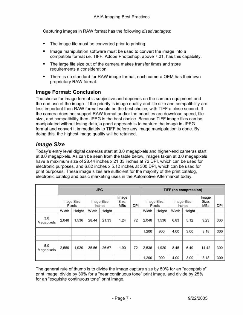
Image Size Today’s entry level digital cameras start at 3.0 megapixels and higher-end cameras start at 8.0 megapixels. As can be seen from the table below, images taken at 3.0 megapixels have a maximum size of 28.44 inches x 21.33 inches at 72 DPI, which can be used for electronic purposes, and 6.82 inches x 5.12 inches at 300 DPI, which can be used for print purposes. These image sizes are sufficient for the majority of the print catalog, electronic catalog and basic marketing uses in the Automotive Aftermarket today.
JPG TIFF (no compression)
Image Size:
Pixels Image Size:
Inches
Image Size: MBs DPI
Image Size: Pixels
Image Size: Inches
Image Size: MBs DPI
Width Height Width Height Width Height Width Height
3.0 Megapixels 2,048 1,536 28.44 21.33 1.24 72 2,048 1,536 6.83 5.12 9.23 300
1,200 900 4.00 3.00 3.18 300
5.0 Megapixels 2,560 1,920 35.56 26.67 1.90 72 2,536 1,920 8.45 6.40 14.42 300
1,200 900 4.00 3.00 3.18 300
The general rule of thumb is to divide the image capture size by 50% for an "acceptable" print image, divide by 30% for a "near continuous tone" print image, and divide by 25% for an “exquisite continuous tone” print image.
AAIA Imaging Best Practices
- Page 8 - 9/22/2005
Image Processing The methods, techniques, and equipment employed when capturing and processing part images are subjective and not within the scope of the Imaging Workgroup discussions. The quality of the final image depends on many factors working in unison. Although, the imaging specifications guidelines included in this document will have a positive affect on the overall quality of the image i.e. a white background and the removal of shadows. Image quality depends on;
The equipment used; camera and lighting.
Environmental control; lighting, product angles, shadows etc.
Photography techniques.
Postproduction image processing; color correction, background, levels etc.
AAIA Imaging Best Practices
- Page 9 - 9/22/2005
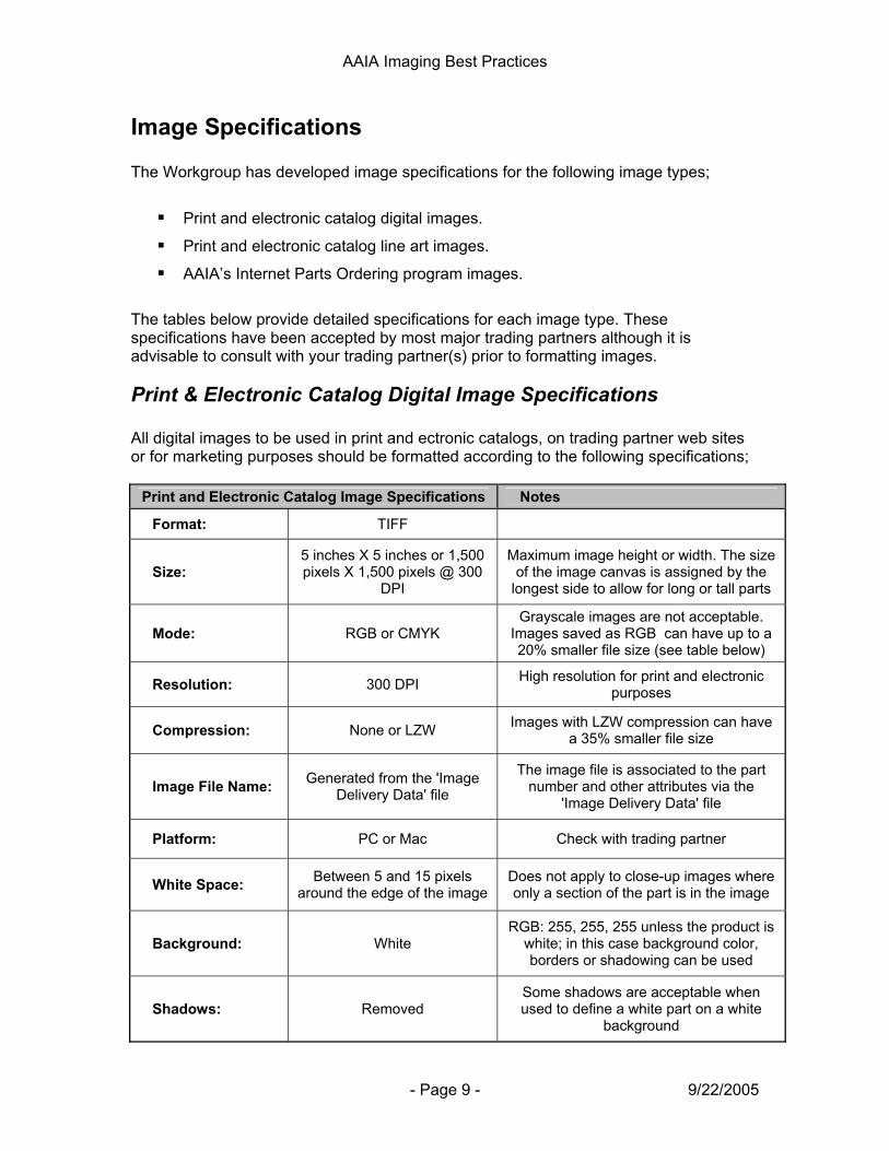
Image Specifications The Workgroup has developed image specifications for the following image types;
Print and electronic catalog digital images.
Print and electronic catalog line art images.
AAIA’s Internet Parts Ordering program images.
The tables below provide detailed specifications for each image type. These specifications have been accepted by most major trading partners although it is advisable to consult with your trading partner(s) prior to formatting images.
Print & Electronic Catalog Digital Image Specifications All digital images to be used in print and ectronic catalogs, on trading partner web sites or for marketing purposes should be formatted according to the following specifications;
Print and Electronic Catalog Image Specifications Notes
Format: TIFF
Size: 5 inches X 5 inches or 1,500 pixels X 1,500 pixels @ 300
DPI
Maximum image height or width. The size of the image canvas is assigned by the
longest side to allow for long or tall parts
Mode: RGB or CMYK Grayscale images are not acceptable.
Images saved as RGB can have up to a 20% smaller file size (see table below)
Resolution: 300 DPI High resolution for print and electronic purposes
Compression: None or LZW Images with LZW compression can have a 35% smaller file size
Image File Name: Generated from the 'Image Delivery Data' file
The image file is associated to the part number and other attributes via the
'Image Delivery Data' file
Platform: PC or Mac Check with trading partner
White Space: Between 5 and 15 pixels around the edge of the image
Does not apply to close-up images where only a section of the part is in the image
Background: White RGB: 255, 255, 255 unless the product is
white; in this case background color, borders or shadowing can be used
Shadows: Removed Some shadows are acceptable when used to define a white part on a white
background
AAIA Imaging Best Practices
- Page 10 - 9/22/2005
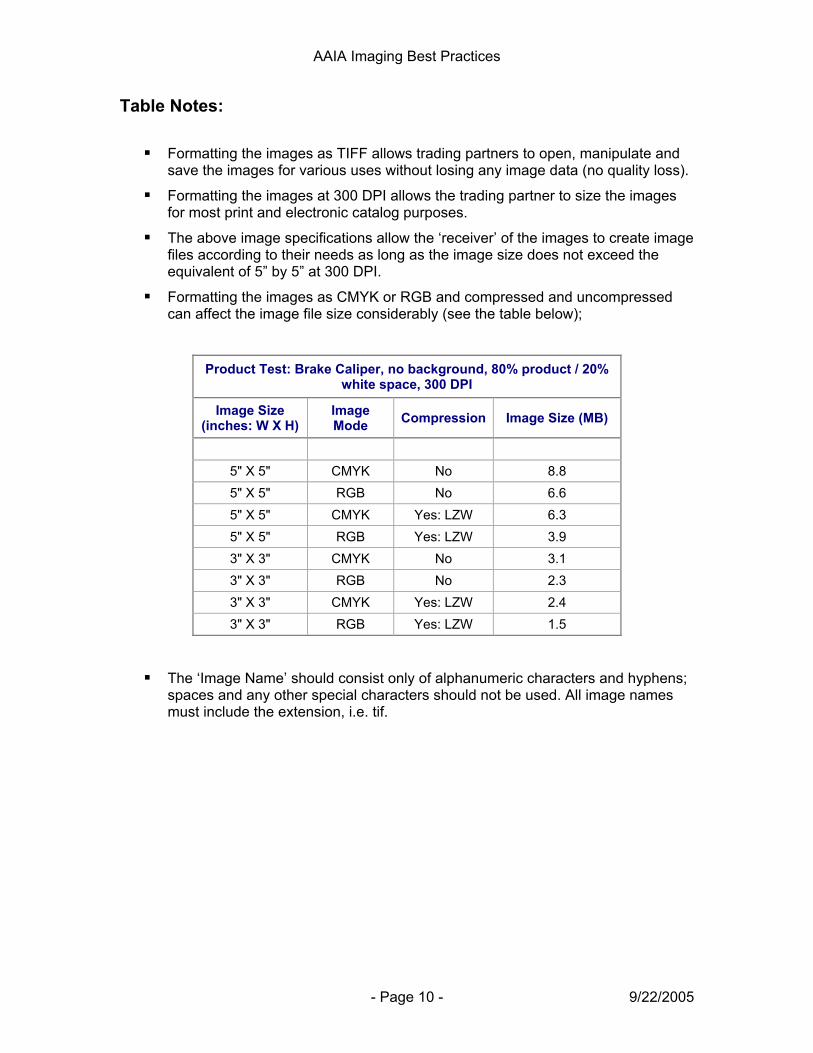
Table Notes:
Formatting the images as TIFF allows trading partners to open, manipulate and save the images for various uses without losing any image data (no quality loss).
Formatting the images at 300 DPI allows the trading partner to size the images for most print and electronic catalog purposes.
The above image specifications allow the ‘receiver’ of the images to create image files according to their needs as long as the image size does not exceed the equivalent of 5” by 5” at 300 DPI.
Formatting the images as CMYK or RGB and compressed and uncompressed can affect the image file size considerably (see the table below);
Product Test: Brake Caliper, no background, 80% product / 20% white space, 300 DPI
Image Size (inches: W X H)
Image Mode Compression Image Size (MB)
5" X 5" CMYK No 8.8 5" X 5" RGB No 6.6 5" X 5" CMYK Yes: LZW 6.3 5" X 5" RGB Yes: LZW 3.9 3" X 3" CMYK No 3.1 3" X 3" RGB No 2.3 3" X 3" CMYK Yes: LZW 2.4 3" X 3" RGB Yes: LZW 1.5
The ‘Image Name’ should consist only of alphanumeric characters and hyphens; spaces and any other special characters should not be used. All image names must include the extension, i.e. tif.
AAIA Imaging Best Practices
- Page 11 - 9/22/2005
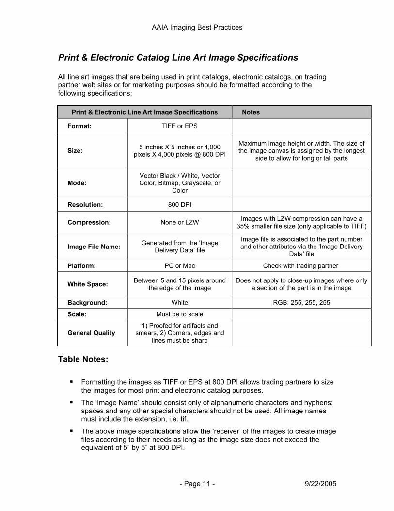
Print & Electronic Catalog Line Art Image Specifications All line art images that are being used in print catalogs, electronic catalogs, on trading partner web sites or for marketing purposes should be formatted according to the following specifications;
Print & Electronic Line Art Image Specifications Notes
Format: TIFF or EPS
Size: 5 inches X 5 inches or 4,000 pixels X 4,000 pixels @ 800 DPI
Maximum image height or width. The size of the image canvas is assigned by the longest
side to allow for long or tall parts
Mode: Vector Black / White, Vector Color, Bitmap, Grayscale, or
Color
Resolution: 800 DPI
Compression: None or LZW Images with LZW compression can have a 35% smaller file size (only applicable to TIFF)
Image File Name: Generated from the 'Image Delivery Data' file
Image file is associated to the part number and other attributes via the 'Image Delivery
Data' file
Platform: PC or Mac Check with trading partner
White Space: Between 5 and 15 pixels around the edge of the image
Does not apply to close-up images where only a section of the part is in the image
Background: White RGB: 255, 255, 255
Scale: Must be to scale
General Quality 1) Proofed for artifacts and
smears, 2) Corners, edges and lines must be sharp
Table Notes:
Formatting the images as TIFF or EPS at 800 DPI allows trading partners to size the images for most print and electronic catalog purposes.
The ‘Image Name’ should consist only of alphanumeric characters and hyphens; spaces and any other special characters should not be used. All image names must include the extension, i.e. tif.
The above image specifications allow the ‘receiver’ of the images to create image files according to their needs as long as the image size does not exceed the equivalent of 5” by 5” at 800 DPI.
AAIA Imaging Best Practices
- Page 12 - 9/22/2005
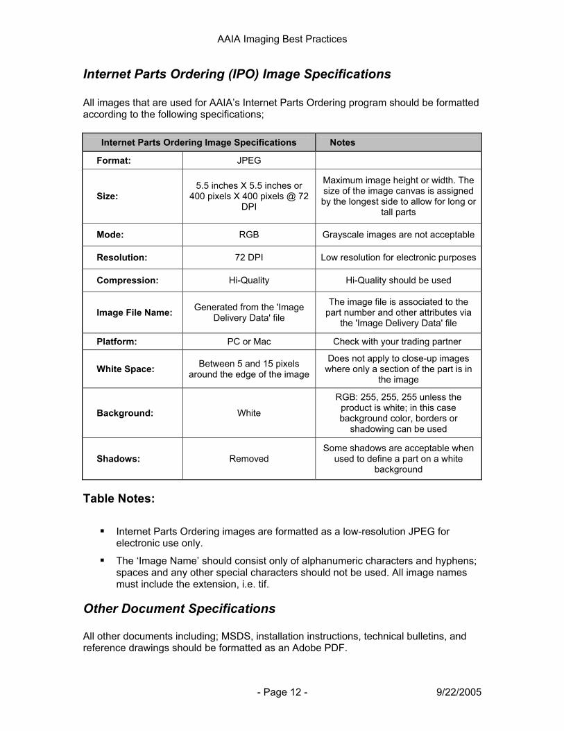
Internet Parts Ordering (IPO) Image Specifications All images that are used for AAIA’s Internet Parts Ordering program should be formatted according to the following specifications;
Internet Parts Ordering Image Specifications Notes
Format: JPEG
Size: 5.5 inches X 5.5 inches or
400 pixels X 400 pixels @ 72 DPI
Maximum image height or width. The size of the image canvas is assigned by the longest side to allow for long or
tall parts
Mode: RGB Grayscale images are not acceptable
Resolution: 72 DPI Low resolution for electronic purposes
Compression: Hi-Quality Hi-Quality should be used
Image File Name: Generated from the 'Image Delivery Data' file
The image file is associated to the part number and other attributes via
the 'Image Delivery Data' file
Platform: PC or Mac Check with your trading partner
White Space: Between 5 and 15 pixels around the edge of the image
Does not apply to close-up images where only a section of the part is in
the image
Background: White
RGB: 255, 255, 255 unless the product is white; in this case background color, borders or
shadowing can be used
Shadows: Removed Some shadows are acceptable when
used to define a part on a white background
Table Notes:
Internet Parts Ordering images are formatted as a low-resolution JPEG for electronic use only.
The ‘Image Name’ should consist only of alphanumeric characters and hyphens; spaces and any other special characters should not be used. All image names must include the extension, i.e. tif.
Other Document Specifications All other documents including; MSDS, installation instructions, technical bulletins, and reference drawings should be formatted as an Adobe PDF.
AAIA Imaging Best Practices
- Page 13 - 9/22/2005
Image Naming Convention All image files delivered to trading partners will be accompanied by the ‘Image Data Delivery’ file (see below). This file associates the image file name to the part number that the image represents making the actual name of the image file irrelevant; it can be named anything at all. The ‘Image Name’ should consist only of alphanumeric characters and hyphens with no spaces. All image names must include the extension, i.e. tif.
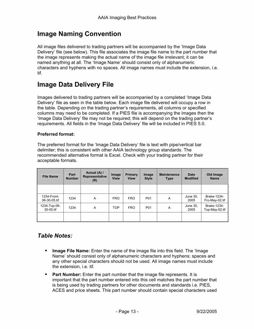
Image Data Delivery File Images delivered to trading partners will be accompanied by a completed ‘Image Data Delivery’ file as seen in the table below. Each image file delivered will occupy a row in the table. Depending on the trading partner’s requirements, all columns or specified columns may need to be completed. If a PIES file is accompanying the images then the ‘Image Data Delivery’ file may not be required; this will depend on the trading partner’s requirements. All fields in the ‘Image Data Delivery’ file will be included in PIES 5.0. Preferred format: The preferred format for the ‘Image Data Delivery’ file is text with pipe/vertical bar delimiter; this is consistent with other AAIA technology group standards. The recommended alternative format is Excel. Check with your trading partner for their acceptable formats.
File Name Part Number
Actual (A) / Representative
(R) Image View
Primary View
Image Style
Maintenance Type
Date Modified
Old Image Name
1234-Front-06-30-05.tif 1234 A FRO FRO P01 A June 30,
2005 Brake-1234-
Fro-May-02.tif 1234-Top-06-
30-05.tif 1234 A TOP FRO P01 A June 30, 2005
Brake-1234-Top-May-02.tif
Table Notes:
Image File Name: Enter the name of the image file into this field. The ‘Image Name’ should consist only of alphanumeric characters and hyphens; spaces and any other special characters should not be used. All image names must include the extension, i.e. tif.
Part Number: Enter the part number that the image file represents. It is important that the part number entered into this cell matches the part number that is being used by trading partners for other documents and standards i.e. PIES, ACES and price sheets. This part number should contain special characters used
AAIA Imaging Best Practices
- Page 14 - 9/22/2005
by the other documents and standards but should not include characters that do not match. Some trading partners may have additional requirements for this filed.
Actual (A) / Representative (R): Enter an ‘A’ into this field if the image is of the actual part or an ‘R’ if the image is a representative image. This follows the same format as PIES.
Image View: Enter the name of the image view into this field. Only the views listed in PIES should be entered into this field unless an arrangement has been made with the trading partner.
Primary View: If there are multiple views for a part number, enter the view that will be used as the primary view for the part. The purpose of the ‘Primary View’ field is to allow the trading partner to identify which image should be used as a ‘feature’ image; for example the first image that displays when the part is searched.
Image Style: Enter the image type according to the format in PIES (IMAG Segment Codes table). Examples of ‘Image Style’ is; Technical Bulletin, Technical Drawings, Installation Instructions, Digital Image, Line Art, MSDS etc.
Maintenance Type: Enter the code that applies to the image according to the following definitions:
o ‘A’ should be used when the image is to be added to the trading partner’s image repository / server / database
o ‘D’ should be used when the image is to be deleted or removed from the trading partner’s image repository / server / database
o ‘C’ should be used when the image is to replace or change an existing image in the trading partner’s image repository / server / database. The contents of the ‘Old Image Name’ field will be relevant when this maintenance type is used.
o ‘N’ should be used when the image does not change; in other words the image record is to be ignored. This maintenance type should only be used only when a complete set of images is sent to the trading partner which includes images that need to be added, deleted and/or changed as well as images that do not need to be added, deleted or changed.
Date Modified: Enter the date the image was modified. This will act as a date stamp for the image.
Old Image Name: If the image is replacing an image that the trading partner already has (in other words it is a new updated image) enter the name of the old image in this field.
AAIA Imaging Best Practices
- Page 15 - 9/22/2005
Image Distribution Method The three methods of distributing images to trading partners are; 1) on CD-ROM or DVD and sent to trading partners accompanied by a ‘Image Data Delivery’ file, 2) by accessing the trading partner’s web server; the location of the image / image folder URL would be obtained through a PIES file (the ‘Image Data Delivery’ file does not support a web server URL), or 3) encoded in valid XML characters using BINHEX or BASE64 encoding and sent to trading partners in a PIES file. Trading partners may prefer one method over the other, accept either method or require the use of only one method; consult the trading partner accordingly.
1. CD-ROM or DVD: This method can be used when distributing small or large quantities of images to trading partners. The Imaging Workgroup recommends that when large quantities of image files are distributed, this method be used simply because method 3) below will result in an unmanageably large file. For example, if 2,000 images are sent to trading partner A from image creator B encoded in an XML file the time to transfer the file would be unreasonable.
Note: When sending images to trading partners on CD-ROM or DVD it is important to separate the images into a logical folder or media structure based on brand or other important differentiating aspects. This will allow the trading partners to easily access the images they need.
2. Access to trading partner’s web server: This method can be used when an
‘image creator’ (i.e. a manufacturer) provides trading partner (i.e. retailers / eCat providers) access to a server for the purpose of downloading specific images.
3. BINHEX or BASE64 Encoded: This method will work well when sending small
quantities of image files to trading partners. The following are some examples of when you might use this method;
a. Sending a small number of image files for update with your trading partner.
b. Sending supporting image documents like MSDS sheets, and reference and installation drawings.
Line Art Images Depending on the product line and trading partner, line art images may be required in addition to digital images. In general, digital images are required for all parts and line art images are only required for specific product lines. Because the list of part names that require line art images differs considerably between trading partners it is best to check with your trading partners for their specific requirements.
AAIA Imaging Best Practices
- Page 16 - 9/22/2005
Representative Image Definition A Representative Image is a digital image that is an “exact likeness” of a part number, but it is not captured from the actual part number being described. Thus, to the naked eye, a representative image appears identical to one or more part numbers. The following conditions must be satisfied in order to qualify as a representative image. If any of these conditions are not met, a separate image of each part number is required.
1. Color: The color of the part in the representative image must match the color of the actual parts exactly. The exception to this is if the representative image is accompanied by a color swatch. This color swatch can be a separate image file or as part of the representative image file. Text describing the color codes can also be included on the color swatch, positioned below each color i.e. 01 White, 02 Black etc.
2. Shape: The shape of the part in the representative image must match the shape
of the actual parts exactly.
3. Material: The material of the part in the representative image must match the material of the actual parts exactly. The exception to this is if the representative image is accompanied by a material swatch. This material swatch can be a separate image file or as part of the representative image file. Text describing the material codes can also be included on the material swatch below each material sample i.e. 01 Smooth, 02 Ridged etc.
4. Physical characteristics: The human eye can not discern any physical
characteristic differences between the representative image and the actual parts.
5. Labels, stampings and part numbers: If the labels, stampings and/or part numbers on the part in the representative image match the labels, stampings and/or part numbers of the actual parts exactly then they must not be removed from the representative image. If the color, shape, material and physical characteristics conditions (points 1-4 above) are met and the labels, stampings and/or part numbers on the part in the representative image are different than the labels, stampings and/or part numbers of the actual parts they must be removed from the representative image. Note: only remove the part attributes that are different; for example, if the labels and stampings are the same for all the actual parts that the representative image is representing but the part numbers are different on each actual part, remove only the part numbers from the representative image and do not remove the labels and stampings.
AAIA Imaging Best Practices
- Page 17 - 9/22/2005
Acceptable Part Image View Definition An acceptable image view of a part is an image view that displays the key physical characteristics of the part from the perspective of the persons who are viewing the image. The persons viewing the image should be able to clearly identify and determine that this image represents the right part satisfying their need and application. Specifically, an acceptable part image view should meet the following conditions;
1. Key Part Features: The image view or views of the part should clearly display the important features and physical attributes of the part or parts.
2. Part Connectors: If the part has connectors and these connectors are important
for the viewer of the image to accurately determine whether the image represents the part they require, these connectors should be imaged at an angle offering the user a definitive view of the connectors so that they can confirm that the image represents the part they require.
3. Installer / Fitment Views: Image views of the part should be captured so that an
installer can clearly see the features of the part that are important from the perspective of installing the part on a make / model / year vehicle.
AAIA Imaging Best Practices
- Page 18 - 9/22/2005
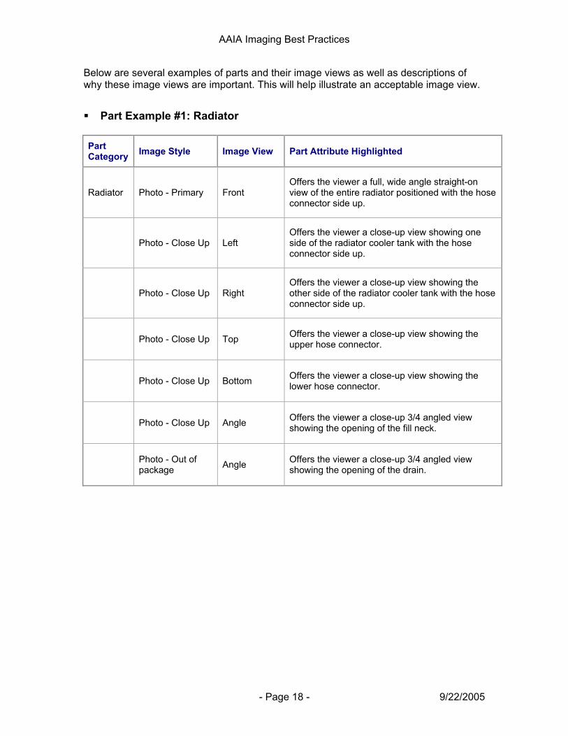
Below are several examples of parts and their image views as well as descriptions of why these image views are important. This will help illustrate an acceptable image view.
Part Example #1: Radiator Part Category Image Style Image View Part Attribute Highlighted
Radiator Photo - Primary Front Offers the viewer a full, wide angle straight-on view of the entire radiator positioned with the hose connector side up.
Photo - Close Up Left Offers the viewer a close-up view showing one side of the radiator cooler tank with the hose connector side up.
Photo - Close Up Right Offers the viewer a close-up view showing the other side of the radiator cooler tank with the hose connector side up.
Photo - Close Up Top Offers the viewer a close-up view showing the upper hose connector.
Photo - Close Up Bottom Offers the viewer a close-up view showing the lower hose connector.
Photo - Close Up Angle Offers the viewer a close-up 3/4 angled view showing the opening of the fill neck.
Photo - Out of package Angle Offers the viewer a close-up 3/4 angled view
showing the opening of the drain.

AAIA Imaging Best Practices
- Page 19 - 9/22/2005
Part Example #2: Compressor Part Category Image Style Image View Part Attribute Highlighted
Compressor Photo - Primary Top Offers the viewer a full wide 3/4 side / top view showing the entire compressor.
Photo - Out of package Connector
Offers the viewer a close-up view showing the terminals and indexing tabs of the electrical connector.
Photo - Close Up Connector Offers the viewer a close-up view showing the hose connection ports.
Photo - Close Up Back Offers the viewer a close-up view showing the back of the compressor with any mounting area details.
Photo - Close Up Front Offers the viewer a close-up front view slightly angled showing the front of the compressor with mounting area details.
Photo - Close Up Side Offers the viewer a close-up view showing the side of the compressor capturing the pulley groves and any mounting area details.
Part Example #3: Fuel Pump
Part Category Image Style Image View Part Attribute Highlighted
Fuel Pump Photo - Primary Top Offers the viewer a full wide 3/4 side / top view showing the entire fuel pump.
Photo - Close Up Connector Offers the viewer a close-up view showing the terminals and indexing tabs of the electrical connector.
Photo - Out of package Connector Offers the viewer a close-up view showing the
fuel line connector.
Photo - Close Up Top Offers the viewer a close-up view showing the full top of the part.
Photo - Close Up Side Offers the viewer a close-up view showing the full side view of the part.
Photo - Out of package Kit Offers a view showing the part with additional
component parts included with the package.
AAIA Imaging Best Practices
- Page 20 - 9/22/2005
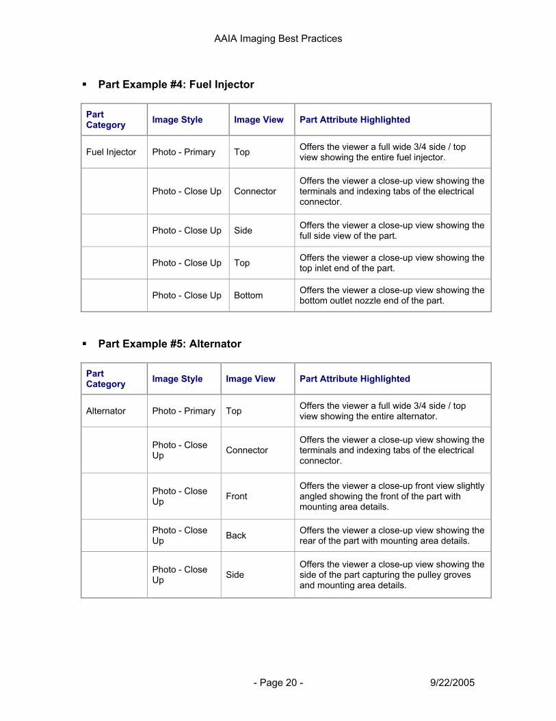
Part Example #4: Fuel Injector
Part Category Image Style Image View Part Attribute Highlighted
Fuel Injector Photo - Primary Top Offers the viewer a full wide 3/4 side / top view showing the entire fuel injector.
Photo - Close Up Connector Offers the viewer a close-up view showing the terminals and indexing tabs of the electrical connector.
Photo - Close Up Side Offers the viewer a close-up view showing the full side view of the part.
Photo - Close Up Top Offers the viewer a close-up view showing the top inlet end of the part.
Photo - Close Up Bottom Offers the viewer a close-up view showing the bottom outlet nozzle end of the part.
Part Example #5: Alternator
Part Category Image Style Image View Part Attribute Highlighted
Alternator Photo - Primary Top Offers the viewer a full wide 3/4 side / top view showing the entire alternator.
Photo - Close Up Connector
Offers the viewer a close-up view showing the terminals and indexing tabs of the electrical connector.
Photo - Close Up Front
Offers the viewer a close-up front view slightly angled showing the front of the part with mounting area details.
Photo - Close Up Back Offers the viewer a close-up view showing the
rear of the part with mounting area details.
Photo - Close Up Side
Offers the viewer a close-up view showing the side of the part capturing the pulley groves and mounting area details.

AAIA Imaging Best Practices
- Page 21 - 9/22/2005
Image Management and Distribution There are many aspects of image management and distribution that are important to all supply chain participants including;
Image library management: This includes managing images by part number, trading partner, image views, date images captured, date images delivered, etc.
Image coverage management: This includes managing images that have and have not been captured and delivered to trading partners.
Image delivery management: This includes managing when and which images are delivered to trading partners.
Image delivery procedures: This includes the procedures that retailers and electronic catalog providers establish for delivering images and image related data.
Supplier approval / reject procedures: This includes the procedures established by trading partners for the approval and rejection of images.
Image update procedures: This includes the procedures for sending replacement images to trading partners.
Although these issues and procedures are very important, for the most part they are managed between trading partners and therefore not within the scope of the Imaging Workgroup Best Practices Guidelines.
AAIA Imaging Best Practices
- Page 22 - 9/22/2005
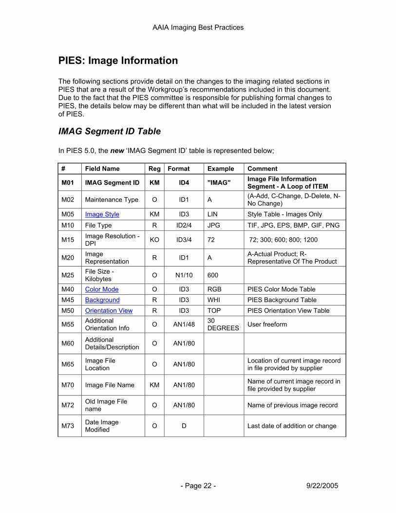
PIES: Image Information The following sections provide detail on the changes to the imaging related sections in PIES that are a result of the Workgroup’s recommendations included in this document. Due to the fact that the PIES committee is responsible for publishing formal changes to PIES, the details below may be different than what will be included in the latest version of PIES.
IMAG Segment ID Table In PIES 5.0, the new ‘IMAG Segment ID’ table is represented below; # Field Name Reg Format Example Comment
M01 IMAG Segment ID KM ID4 "IMAG" Image File Information Segment - A Loop of ITEM
M02 Maintenance Type O ID1 A (A-Add, C-Change, D-Delete, N-No Change)
M05 Image Style KM ID3 LIN Style Table - Images Only
M10 File Type R ID2/4 JPG TIF, JPG, EPS, BMP, GIF, PNG
M15 Image Resolution - DPI KO ID3/4 72 72; 300; 600; 800; 1200
M20 Image Representation R ID1 A A-Actual Product; R-
Representative Of The Product
M25 File Size - Kilobytes O N1/10 600
M40 Color Mode O ID3 RGB PIES Color Mode Table M45 Background R ID3 WHI PIES Background Table M50 Orientation View R ID3 TOP PIES Orientation View Table
M55 Additional Orientation Info O AN1/48 30
DEGREES User freeform
M60 Additional Details/Description O AN1/80
M65 Image File Location O AN1/80 Location of current image record
in file provided by supplier
M70 Image File Name KM AN1/80 Name of current image record in file provided by supplier
M72 Old Image File name O AN1/80 Name of previous image record
M73 Date Image Modified O D Last date of addition or change
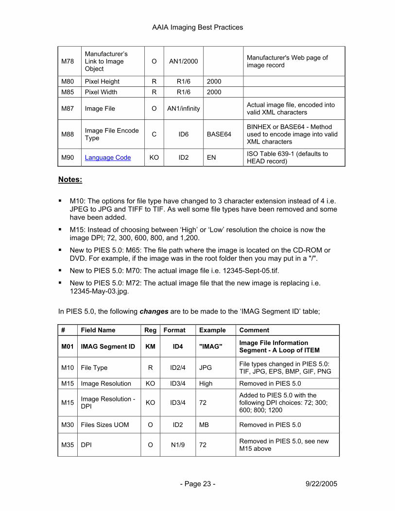
AAIA Imaging Best Practices
- Page 23 - 9/22/2005
M78 Manufacturer’s Link to Image Object
O AN1/2000 Manufacturer's Web page of image record
M80 Pixel Height R R1/6 2000 M85 Pixel Width R R1/6 2000
M87 Image File O AN1/infinity Actual image file, encoded into valid XML characters
M88 Image File Encode Type C ID6 BASE64
BINHEX or BASE64 - Method used to encode image into valid XML characters
M90 Language Code KO ID2 EN ISO Table 639-1 (defaults to HEAD record)
Notes: M10: The options for file type have changed to 3 character extension instead of 4 i.e.
JPEG to JPG and TIFF to TIF. As well some file types have been removed and some have been added.
M15: Instead of choosing between ‘High’ or ‘Low’ resolution the choice is now the image DPI; 72, 300, 600, 800, and 1,200.
New to PIES 5.0: M65: The file path where the image is located on the CD-ROM or DVD. For example, if the image was in the root folder then you may put in a "/".
New to PIES 5.0: M70: The actual image file i.e. 12345-Sept-05.tif.
New to PIES 5.0: M72: The actual image file that the new image is replacing i.e. 12345-May-03.jpg.
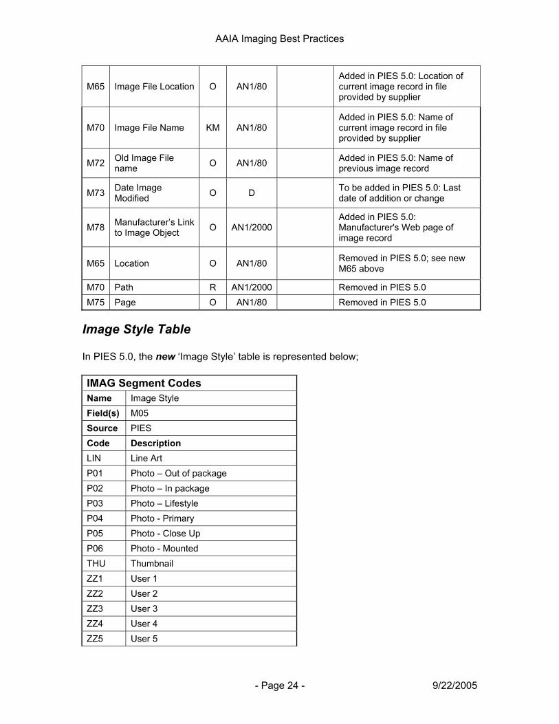
In PIES 5.0, the following changes are to be made to the ‘IMAG Segment ID’ table; # Field Name Reg Format Example Comment
M01 IMAG Segment ID KM ID4 "IMAG" Image File Information Segment - A Loop of ITEM
M10 File Type R ID2/4 JPG File types changed in PIES 5.0: TIF, JPG, EPS, BMP, GIF, PNG
M15 Image Resolution KO ID3/4 High Removed in PIES 5.0
M15 Image Resolution - DPI KO ID3/4 72
Added to PIES 5.0 with the following DPI choices: 72; 300; 600; 800; 1200
M30 Files Sizes UOM O ID2 MB Removed in PIES 5.0
M35 DPI O N1/9 72 Removed in PIES 5.0, see new M15 above
AAIA Imaging Best Practices
- Page 24 - 9/22/2005
M65 Image File Location O AN1/80 Added in PIES 5.0: Location of current image record in file provided by supplier
M70 Image File Name KM AN1/80 Added in PIES 5.0: Name of current image record in file provided by supplier
M72 Old Image File name O AN1/80 Added in PIES 5.0: Name of
previous image record
M73 Date Image Modified O D To be added in PIES 5.0: Last
date of addition or change
M78 Manufacturer’s Link to Image Object O AN1/2000
Added in PIES 5.0: Manufacturer's Web page of image record
M65 Location O AN1/80 Removed in PIES 5.0; see new M65 above
M70 Path R AN1/2000 Removed in PIES 5.0 M75 Page O AN1/80 Removed in PIES 5.0
Image Style Table In PIES 5.0, the new ‘Image Style’ table is represented below; IMAG Segment Codes Name Image Style Field(s) M05 Source PIES Code Description LIN Line Art P01 Photo – Out of package P02 Photo – In package P03 Photo – Lifestyle P04 Photo - Primary P05 Photo - Close Up P06 Photo - Mounted THU Thumbnail ZZ1 User 1 ZZ2 User 2 ZZ3 User 3 ZZ4 User 4 ZZ5 User 5
AAIA Imaging Best Practices
- Page 25 - 9/22/2005
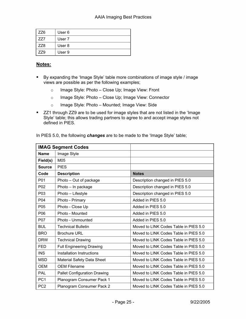
ZZ6 User 6 ZZ7 User 7 ZZ8 User 8 ZZ9 User 9
Notes:
By expanding the ‘Image Style’ table more combinations of image style / image views are possible as per the following examples;
o Image Style: Photo – Close Up; Image View: Front
o Image Style: Photo – Close Up; Image View: Connector
o Image Style: Photo – Mounted; Image View: Side
ZZ1 through ZZ9 are to be used for image styles that are not listed in the ‘Image Style’ table; this allows trading partners to agree to and accept image styles not defined in PIES.
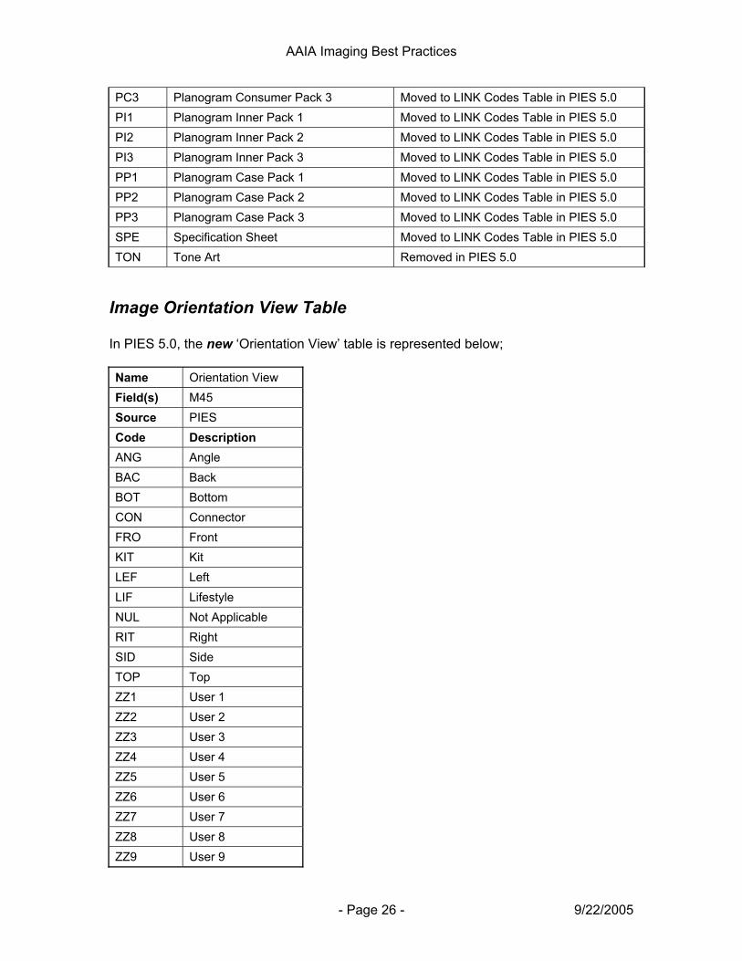
In PIES 5.0, the following changes are to be made to the ‘Image Style’ table; IMAG Segment Codes Name Image Style Field(s) M05 Source PIES Code Description Notes P01 Photo – Out of package Description changed in PIES 5.0 P02 Photo – In package Description changed in PIES 5.0 P03 Photo – Lifestyle Description changed in PIES 5.0 P04 Photo - Primary Added in PIES 5.0 P05 Photo - Close Up Added in PIES 5.0 P06 Photo - Mounted Added in PIES 5.0 P07 Photo - Unmounted Added in PIES 5.0 BUL Technical Bulletin Moved to LINK Codes Table in PIES 5.0 BRO Brochure URL Moved to LINK Codes Table in PIES 5.0 DRW Technical Drawing Moved to LINK Codes Table in PIES 5.0 FED Full Engineering Drawing Moved to LINK Codes Table in PIES 5.0 INS Installation Instructions Moved to LINK Codes Table in PIES 5.0 MSD Material Safety Data Sheet Moved to LINK Codes Table in PIES 5.0 OEM OEM Filename Moved to LINK Codes Table in PIES 5.0 PAL Pallet Configuration Drawing Moved to LINK Codes Table in PIES 5.0 PC1 Planogram Consumer Pack 1 Moved to LINK Codes Table in PIES 5.0 PC2 Planogram Consumer Pack 2 Moved to LINK Codes Table in PIES 5.0
AAIA Imaging Best Practices
- Page 26 - 9/22/2005
PC3 Planogram Consumer Pack 3 Moved to LINK Codes Table in PIES 5.0 PI1 Planogram Inner Pack 1 Moved to LINK Codes Table in PIES 5.0 PI2 Planogram Inner Pack 2 Moved to LINK Codes Table in PIES 5.0 PI3 Planogram Inner Pack 3 Moved to LINK Codes Table in PIES 5.0 PP1 Planogram Case Pack 1 Moved to LINK Codes Table in PIES 5.0 PP2 Planogram Case Pack 2 Moved to LINK Codes Table in PIES 5.0 PP3 Planogram Case Pack 3 Moved to LINK Codes Table in PIES 5.0 SPE Specification Sheet Moved to LINK Codes Table in PIES 5.0 TON Tone Art Removed in PIES 5.0
Image Orientation View Table In PIES 5.0, the new ‘Orientation View’ table is represented below; Name Orientation View Field(s) M45 Source PIES Code Description ANG Angle BAC Back BOT Bottom CON Connector FRO Front KIT Kit LEF Left LIF Lifestyle NUL Not Applicable RIT Right SID Side TOP Top ZZ1 User 1 ZZ2 User 2 ZZ3 User 3 ZZ4 User 4 ZZ5 User 5 ZZ6 User 6 ZZ7 User 7 ZZ8 User 8 ZZ9 User 9

AAIA Imaging Best Practices
- Page 27 - 9/22/2005
Notes:
ZZ1 through ZZ9 are to be used for image views that are not listed in the ‘Orientation View’ table; this allows trading partners to agree to and accept image views not defined in PIES.
In PIES 5.0, the following changes are to be made to the ‘Orientation View’ table; Name Orientation View Field(s) M45 Source PIES Code Description Notes ANG Angle Description changed from 'Angle View' to 'Angle' in PIES 5.0 CON Connector Added in PIES 5.0 KIT Kit Added in PIES 5.0 LEF Left Added in PIES 5.0 LIF Lifestyle Removed and moved to the 'Image Style' table OTH Other Removed in PIES 5.0 RIT Right Added in PIES 5.0 ZZ1 User 1 Added in PIES 5.0 ZZ2 User 2 Added in PIES 5.0 ZZ3 User 3 Added in PIES 5.0 ZZ4 User 4 Added in PIES 5.0 ZZ5 User 5 Added in PIES 5.0 ZZ6 User 6 Added in PIES 5.0 ZZ7 User 7 Added in PIES 5.0 ZZ8 User 8 Added in PIES 5.0 ZZ9 User 9 Added in PIES 5.0
Color Mode Table In PIES 5.0, the new ‘Color Mode’ table is represented below; Name Color Mode Field(s) M40 Source PIES Code Description RGB RGB CMY CMYK

AAIA Imaging Best Practices
- Page 28 - 9/22/2005
GRA Gray Scale OTH Other WEB Vector B/W VEC Vector Color BIT Bitmap
Notes: Additional ‘Color Mode’ options added to accommodate line art color modes.
In PIES 5.0, the following changes are to be made to the ‘Color Mode’ table; Name Color Mode Field(s) M40 Source PIES Code Description Notes WEB Vector B/W Added in PIES 5.0 VEC Vector Color Added in PIES 5.0 BIT Bitmap Added in PIES 5.0
LINK Segment ID Table In PIES 5.0, the new ‘LINK Segment ID’ table is represented below; # Field Name Reg Format Example Comment
L01 LINK Segment ID KM ID4 "LINK" Uniform Resource Location (URL) or File Reference Segment - A Loop of ITEM
L02 Maintenance Type O ID1 A (A-Add, C-Change, D-Delete, N-No Change)
L04 Document Name KM AN1/80 Name of the current document as provided by supplier
L05 LINK Code KM ID3 PIC PIES Link Code Table.
L10 File Type PDF PDF,TIF, DOC, JPG, EPS
L15 Document URL E AN1/2000 Manufacturer's Web page of document format
L20 Image File O AN1/Infinity Actual image file, encoded into Valid XML characters
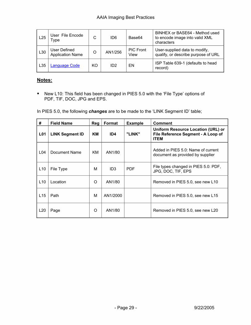
AAIA Imaging Best Practices
- Page 29 - 9/22/2005
L25 User File Encode Type C ID6 Base64
BINHEX or BASE64 - Method used to encode image into valid XML characters
L30 User Defined Application Name O AN1/256 PIC Front
View User-supplied data to modify, qualify, or describe purpose of URL
L35 Language Code KO ID2 EN ISP Table 639-1 (defaults to head record)
Notes: New L10: This field has been changed in PIES 5.0 with the ‘File Type’ options of
PDF, TIF, DOC, JPG and EPS. In PIES 5.0, the following changes are to be made to the ‘LINK Segment ID’ table; # Field Name Reg Format Example Comment
L01 LINK Segment ID KM ID4 "LINK" Uniform Resource Location (URL) or File Reference Segment - A Loop of ITEM
L04 Document Name KM AN1/80 Added in PIES 5.0: Name of current document as provided by supplier
L10 File Type M ID3 PDF File types changed in PIES 5.0: PDF, JPG, DOC, TIF, EPS
L10 Location O AN1/80 Removed in PIES 5.0, see new L10
L15 Path M AN1/2000 Removed in PIES 5.0, see new L15
L20 Page O AN1/80 Removed in PIES 5.0, see new L20
AAIA Imaging Best Practices
- Page 30 - 9/22/2005
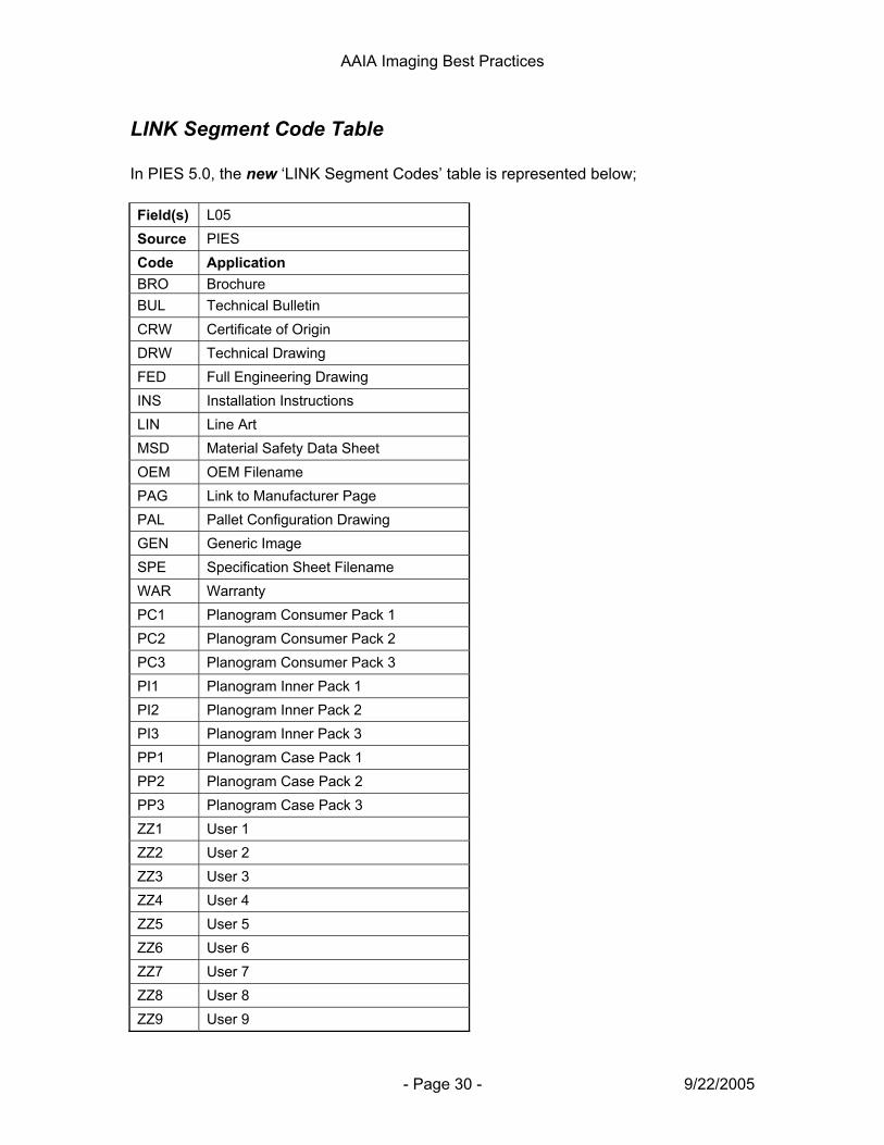
LINK Segment Code Table In PIES 5.0, the new ‘LINK Segment Codes’ table is represented below; Field(s) L05 Source PIES Code Application BRO Brochure BUL Technical Bulletin CRW Certificate of Origin DRW Technical Drawing FED Full Engineering Drawing INS Installation Instructions LIN Line Art MSD Material Safety Data Sheet OEM OEM Filename PAG Link to Manufacturer Page PAL Pallet Configuration Drawing GEN Generic Image SPE Specification Sheet Filename WAR Warranty PC1 Planogram Consumer Pack 1 PC2 Planogram Consumer Pack 2 PC3 Planogram Consumer Pack 3 PI1 Planogram Inner Pack 1 PI2 Planogram Inner Pack 2 PI3 Planogram Inner Pack 3 PP1 Planogram Case Pack 1 PP2 Planogram Case Pack 2 PP3 Planogram Case Pack 3 ZZ1 User 1 ZZ2 User 2 ZZ3 User 3 ZZ4 User 4 ZZ5 User 5 ZZ6 User 6 ZZ7 User 7 ZZ8 User 8 ZZ9 User 9

AAIA Imaging Best Practices
- Page 31 - 9/22/2005
In PIES 5.0, the following changes are to be made to the ‘LINK Segment Codes’ table; LINK Segment Codes
Name LINK Code
Field(s) L05
Source PIES
Code Application Notes
BRO Brochure Moved from IMAG Codes Table; no 'URL' in name
BUL Technical Bulletin Moved from IMAG Codes Table; no 'URL' in name
DRW Technical Drawing Moved from IMAG Codes Table; no 'URL' in name
FED Full Engineering Drawing Moved from IMAG Codes Table; no 'URL' in name
INS Installation Instructions Moved from IMAG Codes Table; no 'URL' in name
LIN Line Art No 'URL' in name
MSD Material Safety Data Sheet Moved from IMAG Codes Table; no 'MSDS' or 'URL' in name
OEM OEM Filename Moved from IMAG Codes Table
PAG Link to Manufacturer Page Added in PIES 5.0
PAL Pallet Configuration Drawing Moved from IMAG Codes Table; no 'URL' in name
GEN Generic Image Added in PIES 5.0
SPE Specification Sheet Filename Moved from IMAG Codes Table
WAR Warranty No 'URL' in name
PC1 Planogram Consumer Pack 1 Moved from IMAG Codes Table
PC2 Planogram Consumer Pack 2 Moved from IMAG Codes Table
PC3 Planogram Consumer Pack 3 Moved from IMAG Codes Table
PI1 Planogram Inner Pack 1 Moved from IMAG Codes Table
PI2 Planogram Inner Pack 2 Moved from IMAG Codes Table
PI3 Planogram Inner Pack 3 Moved from IMAG Codes Table
PP1 Planogram Case Pack 1 Moved from IMAG Codes Table
PP2 Planogram Case Pack 2 Moved from IMAG Codes Table
PP3 Planogram Case Pack 3 Moved from IMAG Codes Table
AAIA Imaging Best Practices
- Page 32 - 9/22/2005
Image Protection, Copyright and Ownership The issues regarding the protection, copyright and ownership of images as they are traded throughout the supply chain is a concern to both the creator of the images and the trading partner who is using the images. The main area of concern is the use of the images for electronic purposes; online catalogs, Extranets, and e-commerce sites. Images published online are vulnerable to misappropriation. The image creator (the supplier) requires an assurance that their images are being reasonably protected while in use by their trading partners against theft and misuse. The receivers of the images (the retailers and eCat providers) require the flexibility to use the images in various marketing capacities in order to maximize their ability to sell parts. The following are the Workgroup recommendations regarding image protection, copyright and ownership;
Image Protection: This issue involves protecting the creator’s images while they are in use by the trading partner for both print and electronic purposes.
o Image Watermarks: The majority of retailers and eCat providers feel that watermarks are a distraction to the viewer of the image and should therefore not be used. Although, in certain cases trading partners will accept watermarked images. It is recommended that before watermarks are applied each trading partner’s policy regarding this issue is reviewed.
o Intended Image Use: All retailers and eCat providers are using the images for the purpose of selling more of the right parts to the right customers. The workgroup consensus is that the image receivers will protect the images electronically to the best of their ability and they will discontinue using the images if the image creator no longer supplies the parts that the images represent to the trading partner.
o Legal Agreements: Some retailers and eCat providers are prepared to enter into legal agreements with the image creators addressing the use, protection, and ownership of the images. The image creators should check with their trading partners to discuss possible legal agreements that protect the image creator’s asset (the images).
Ownership and Copyright: This issue addresses the copyright and ownership
of the images.
o The issue of copyright and ownership involves determining whether or not the creator of the images owns the copyright to the images after they have been distributed to supply chain trading partners. In other words, does the copyright of the image transfer to the trading partner or is it retained by the image creator. The Workgroup’s viewpoint is that ownership and copyright of the images is a legal issue between trading partners and therefore not within the scope of the Workgroup’s discussions. Ultimately the ownership of and right to use an image will be governed by the agreement between the image creator and the trading partner.

AAIA Imaging Best Practices
- Page 33 - 9/22/2005
Additions, Suggestions and Feedback Process This document is the result of a collaborative effort between a diverse group of retailers, manufacturers, and electronic catalog and solution providers. Overtime, and as a result of feedback from the industry some of the recommendations in this guideline may be changed and updated. The Imaging Workgroup encourages as much feedback as possible from the Automotive Aftermarket. To provide feedback to the Imaging Workgroup follow the process below;
1. Contact an Imaging Workgroup member or a member of AAIA’s Standards and Technology Committee by writing to [email protected].
2. Explain the issue(s) or make a recommendation(s).
3. The issue(s) or recommendation(s) will be brought up and discussed by the members of the Imaging Workgroup at regularly scheduled meetings.
4. The Imaging Workgroup will make a recommendation(s) which will be included in the next updated version of the Imaging Best Practices Guideline.
5. The recommendation(s) will be published by AAIA in the latest version of the guideline.