MicroTech II AAF®-HermanNelson® Unit Ventilator Unit Controller ...

Replacement Parts List No. 057115700Revision H 01/2018
AAFHerman Nelson
ClassmateConventional Unit Ventilator
AH 001-008
AV 001-006
Vintage B
Last Manufactured: 1997
To find your Daikin Applied parts distributor, call 1-800-377-2787 or visit www.DaikinApplied.com

UV: AH 001-008B, AV 001-006B Rev. H 01/18 RPL 571157 / Page 2
ContentsPARTS LIST REVISION HISTORY .......................................................................................................................................................3NOMENCLATURE Serial Number .................................................................................................................................................................................4 Model Number -AH .......................................................................................................................................................................4-6 Model Number -AV .......................................................................................................................................................................7-9AV/AH UNIT DATAPLATE LOCATION ................................................................................................................................................10AV EXTERNAL CABINETRY Front Access Panels, End and Center ....................................................................................................................................... 11 Top Discharge Grille, Arrangement "A" & "B" .............................................................................................................................12 Top Discharge Duct Collar, Arrangement "C" .............................................................................................................................13 Front Double Deflection Grille, Arrangement "D" .......................................................................................................................14 Top Double Deflection Grille, Arrangement "E" ..........................................................................................................................15 Top Discharge Duct Collar, Arrangement "F" .............................................................................................................................16 1" End Panels .............................................................................................................................................................................17AH EXTERNAL CABINETRY Access Panels ............................................................................................................................................................................18 Access Panel Hardware .............................................................................................................................................................19 Discharge Air Grille w/ Side Deflection Vanes, Bar Stock, Arrangement "A" ..............................................................................20 Top Discharge Duct Collar, Arrangement "C" .....................................................................................................................................21 Front Double Deflection Grille, Arrangement "E" ........................................................................................................................22 Top Discharge Duct Collar, Arrangement "F" .............................................................................................................................23 Double Deflection Grille, Arrangement "G" .................................................................................................................................24 Bar Stock Grille w/ Side Deflection Vanes, Arrangement "H" .....................................................................................................25AV/AH TOUCH-UP PAINT ...................................................................................................................................................................26FAN SECTION AV/AH Bearing Components ......................................................................................................................................................27 AV/AH Motor Components .........................................................................................................................................................28 AH Electrical Data & External Static Pressure Chart .................................................................................................................29 AV/AH Air Filters .........................................................................................................................................................................30AV/AH DAMPER SECTION AV Drain Pan & Coil Frame Blockoff Diagrams AV With Face & Bypass Damper ........................................................................................................................................31 AV Without Face & Bypass Damper ...................................................................................................................................31 AH Drain Pan & Coil Frame Blockoff Diagrams AH With Face & Bypass Damper ........................................................................................................................................32 AH Without Face & Bypass Damper ...................................................................................................................................32 Drain Pan, Coil Frame Blockoff and Face & Bypass Damper Components ..........................................................................33-34 Actuator ......................................................................................................................................................................................35 Outdoor Air & Return Air Damper Diagrams AV Floor Unit (100% Return Air) .........................................................................................................................................36 AH Ceiling Unit ....................................................................................................................................................................36 Damper Spring Kit Diagram .......................................................................................................................................................37 Outdoor Air, Return Air Dampers and Spring Kit Components ...................................................................................................38AV/AH CONTROL VALVE COMPONENTS .........................................................................................................................................39AV/AH COIL SECTION Coils ...........................................................................................................................................................................................40 Coil Mount, Chilled Water Diagram ....................................................................................................................................................41 Coil Mount, Hot Water Diagram ..................................................................................................................................................42 Electric Heat Component Location Diagram ..............................................................................................................................43 Electric Heat Components ..........................................................................................................................................................44 Electric Heat Section Sheathed .............................................................................................................................................................................45 Open Wire ...........................................................................................................................................................................46AV/AH CONTROLS MicroTech Diagram ....................................................................................................................................................................47 MicroTech Components ..............................................................................................................................................................48 Control Box Temperature Control Diagram & Components, "Controls By Others".....................................................................49 Primary Control Box Diagram, Electromechanical Controls .......................................................................................................50 Primary Control Box Diagram, MicroTech Controls ............................................................................................................................51 Specialty Component Locations Diagram ..................................................................................................................................52 Control Box Components Transformers .......................................................................................................................................................................53 Fuses, Cordsets and Receptacles ......................................................................................................................................54 Relays .................................................................................................................................................................................55 Thermostats, Switches and Time Clock ..............................................................................................................................56Critical Parts List.............................................................................................................................................................................CPL1

UV: AH 001-008B, AV 001-006B Rev. H 01/18 RPL 571157 / Page 3
Revision Date Description
---- 04/97 NEW A 07/97 Page 34- Removed; Subheading-Coils (from 4-25-94) Page 34- Removed; table heading - Serial Number Ends in -02 (or higher). B 5/99 Page 27 - Added description and part numbers for Auxillary Drain Pans. C 11/99 Page 13 - Added footnote for Filter Stop (Bub.# 8). Page 22 - Added Bubble #10 to diagram. Added Motor Gasket to list. Page 28 - Updated part numbers for Damper Stop, Rear on all sizes (Bub.# 7). Page 32 - Updated part numbers for Damper, RA on all sizes (Bub.# 102). Page 42 - Added Freezestat Clip. D 09/00 Page 6 - Bub #8 pn corrected, was 4NKE7636 and is now 4NKE7968. Page 7 - Bub #2 pn corrected, was GC10748 and is now GC10145. Page 15 - Bub #2 pn corrected, was GC10748 and is now GC10145. Page 39 - Bub #111 pn corrected, was 4ECA8878 and is now 802007686, (9 places). Page 40 - Bub #111 pn corrected, was 4ECA8878 and is now 802007686, (10 places). Page 43 - Bub #53 pn corrected, was 4EPC9056 and is now 060630801. E 01/02 Page 43 - Bub. # 66 description changed from 'Plug & Receptacle Combo' to just 'Plug'. F 02/06 Page 42 - Freezestat Clip p/n was changed from 4DDZ6424 to 106456801. Page 47 - Transformer, Control 75 VA for 115/460/575V units p/n changed from 062986901 to 062986902. G 05/11 Reformat to CSIV. Add unit sizes to cover. Pages 4-8 - Add Code Index AV & AH. CPL 1 - Add CPL page. H 01/18 Delete sheetmetal & add footnote to contact Daikin. Redo all diagrams. Change unit size thru RPL to include size and CFM. Add size 008 on AH units. CPL1- Update to Daikin format.
Daikin Applied, 13600 Industrial Park Blvd., P.O. Box 1551, Minneapolis, MN 55440 (763) 553-5330
Parts List Revision History

UV: AH 001-008B, AV 001-006B Rev. H 01/18 RPL 571157 / Page 4
NomenclatureSerial Number
Code 01= Unit TypeAH= Ceiling, Unit Ventilator
Code 02= Unit Size001= Series 1000- 500 CFM003= Series 3000- 750 CFM004= Series 4000- 1000 CFM005= Series 5000- 1250 CFM006= Series 6000- 1500 CFM008= Series 8000- 2000 CFM
Code 03= VintageB= Vintage B
Code 04= Unit Voltage01= 230/60/1 27= 460/60/3 03= 208/60/1 29= 230/60/311= 115/60/1 37=575/60/3 12= 208/60/3 47= 265/60/1
Code 05= Face & Bypass Damper F= Face & BypassN= None
Code 06= Temperature Controls Provider BRB= Siebe Pneumatic Factory InstalledHWP= Honeywell Pneumatic Factory Installed JCP= Johnson Pneumatic Factory Installed LGP= Landis Gyr/Powers Pneumatic Factory InstalledBCE= Barber-Colman Electric Factory InstalledMN2= MicroTech Network-ASHRAE Cycle IIMN3= MicroTech Network-ASHRAE Cycle IIIMP2= MicroTech Open Protocol-ASHRAE Cycle IIMP3= MicroTech Open Protocol-ASHRAE Cycle IIIMA2= MicroTech Stand-Alone-ASHRAE Cycle IIMA3= MicroTech Stand-Alone-ASHRAE Cycle IIIMM2= MicroTech Stand-Alone Master-ASHRAE Cycle IIMM3= MicroTech Stand-Alone Master-ASHRAE Cycle IIIMS2= MicroTech Stand-Alone Slave-ASHRAE Cycle IIMS3= MicroTech Stand-Alone Slave-ASHRAE Cycle IIIFLD= Controls By Others
Code 07= MicroTech Occupied/Unoccupied Controls1= Day-Night Changeover Relay, 24V2= Day-Night Changeover Relay, 115V3= Time Clock & Holiday Switch5= NoneY= Controls By Others
Code 08= MicroTech Room Temperature SensorsUY= Unit MountedWY= Wall Mounted w/o TCWT= Wall Mounted w/ TCCY= Wall Mounted w/ Comm Port w/o TCCT= Wall Mounted w/ Comm Port w/ TCYY= Controls By Others
Code 09= MicroTech Tenant OverrideW= Wall Mounted (Part of Wall Sensor) N= NoneY= Controls By OthersW= Wall Mounted (Part of Wall Sensor) N= NoneY= Controls By Others
Code 10= MT Room Temperature Setpoint Adj. ± 3˚FW= Wall Mounted (Part of Wall Sensor) N= NoneY= Controls By Others
Code 11= MicroTech Ventilation RelayA= Ventilation Lockout- 24VB= Ventilation Lockout- 115VC= Ventilation Interlock, Maximum- 24VD= Ventilation Interlock, Maximum- 115VN= NoneY= Controls By Others
Code 12= Shutdown RelayY= None
Code 13= Future Use Only- Always YY
Continued on the next page.
Model Number- AHAH 003 B 01 E HWP 2 WY W Y C Y YY HC3 2M1 A C3 2M7
Code 01 02 03 04 05 06 07 08 09 10 11 12 13 14 15 16 17 18
B LY 1 ST S A 2 2 BT A SFB YY P Y Y Y N YYCode 19 20 21 22 23 24 25 26 27 28 29 30 31 32 33 34 35 36
Year ManufacturedY= 1993 6= 1996 Z= 1994 7= 19975= 1995
7 6 A 12345 00
Plant Identification Number7 = Auburn
Serial Number
Month Manufactured A= January B= February C= March D= April E= May F= June
Engineering Revision
G= July I= August J= September K= October L= November M= December
UV: AH 001-008B, AV 001-006B Rev. H 01/18 RPL 571157 / Page 5
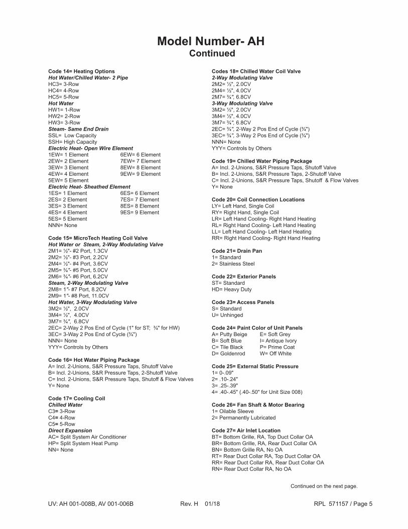
Code 14= Heating OptionsHot Water/Chilled Water- 2 PipeHC3= 3-RowHC4= 4-RowHC5= 5-RowHot WaterHW1= 1-RowHW2= 2-RowHW3= 3-RowSteam- Same End DrainSSL= Low Capacity SSH= High CapacityElectric Heat- Open Wire Element1EW= 1 Element 6EW= 6 Element2EW= 2 Element 7EW= 7 Element3EW= 3 Element 8EW= 8 Element4EW= 4 Element 9EW= 9 Element5EW= 5 ElementElectric Heat- Sheathed Element1ES= 1 Element 6ES= 6 Element2ES= 2 Element 7ES= 7 Element3ES= 3 Element 8ES= 8 Element4ES= 4 Element 9ES= 9 Element5ES= 5 ElementNNN= None
Code 15= MicroTech Heating Coil ValveHot Water or Steam, 2-Way Modulating Valve2M1= ½"- #2 Port, 1.3CV2M2= ½"- #3 Port, 2.2CV2M4= ½"- #4 Port, 3.6CV2M5= ¾"- #5 Port, 5.0CV2M6= ¾"- #6 Port, 6.2CVSteam, 2-Way Modulating Valve 2M8= 1"- #7 Port, 8.2CV2M9= 1"- #8 Port, 11.0CVHot Water, 3-Way Modulating Valve 3M2= ½", 2.0CV3M4= ½", 4.0CV3M7= ¾", 6.8CV2EC= 2-Way 2 Pos End of Cycle (1" for ST; ¾" for HW)3EC= 3-Way 2 Pos End of Cycle (¾")NNN= NoneYYY= Controls by Others
Code 16= Hot Water Piping PackageA= Incl. 2-Unions, S&R Pressure Taps, Shutoff ValveB= Incl. 2-Unions, S&R Pressure Taps, 2-Shutoff ValveC= Incl. 2-Unions, S&R Pressure Taps, Shutoff & Flow ValvesY= None
Code 17= Cooling CoilChilled WaterC3= 3-RowC4= 4-RowC5= 5-RowDirect ExpansionAC= Split System Air ConditionerHP= Split System Heat PumpNN= None
Codes 18= Chilled Water Coil Valve2-Way Modulating Valve2M2= ½", 2.0CV2M4= ½", 4.0CV2M7= ¾", 6.8CV3-Way Modulating Valve 3M2= ½", 2.0CV3M4= ½", 4.0CV3M7= ¾", 6.8CV2EC= ¾", 2-Way 2 Pos End of Cycle (¾")3EC= ¾", 3-Way 2 Pos End of Cycle (¾")NNN= NoneYYY= Controls by Others
Code 19= Chilled Water Piping PackageA= Incl. 2-Unions, S&R Pressure Taps, Shutoff ValveB= Incl. 2-Unions, S&R Pressure Taps, 2-Shutoff ValveC= Incl. 2-Unions, S&R Pressure Taps, Shutoff & Flow ValvesY= None
Code 20= Coil Connection LocationsLY= Left Hand, Single CoilRY= Right Hand, Single CoilLR= Left Hand Cooling- Right Hand HeatingRL= Right Hand Cooling- Left Hand Heating LL= Left Hand Cooling- Left Hand HeatingRR= Right Hand Cooling- Right Hand Heating
Code 21= Drain Pan1= Standard2= Stainless Steel
Code 22= Exterior PanelsST= StandardHD= Heavy Duty
Code 23= Access PanelsS= StandardU= Unhinged
Code 24= Paint Color of Unit PanelsA= Putty Beige E= Soft GreyB= Soft Blue I= Antique IvoryC= Tile Black P= Prime CoatD= Goldenrod W= Off White
Code 25= External Static Pressure1= 0-.09" 2= .10-.24"3= .25-.39"4= .40-.45" (.40-.50" for Unit Size 008)
Code 26= Fan Shaft & Motor Bearing1= Oilable Sleeve2= Permanently Lubricated
Code 27= Air Inlet LocationBT= Bottom Grille, RA, Top Duct Collar OABR= Bottom Grille, RA, Rear Duct Collar OABN= Bottom Grille RA, No OART= Rear Duct Collar RA, Top Duct Collar OARR= Rear Duct Collar RA, Rear Duct Collar OARN= Rear Duct Collar RA, No OA
Continued on the next page.
Model Number- AH Continued

UV: AH 001-008B, AV 001-006B Rev. H 01/18 RPL 571157 / Page 6
Code 28= Outdoor Air DamperA= StandardB= Standard w/Setscrew LockC= Cold Weather InsulatedD= Cold Weather Insulated w/ Setscrew LockR= None, Recirculation Unit
Code 29= Cabinet Mounting & Discharge Air ArrangementSFB= Standard, Front Discharge, Barsock GrilleSFC= Standard, Front Discharge, Duct CollarPFD= Plenum, Front Discharge, Double Deflection GrillePBD= Plenum, Bottom Discharge, Double Deflection GrillePFC= Plenum, Front Discharge, Duct CollarPFB= Plenum, Front Discharge, Barsock Grille
Code 30= Future Use Only- Always YY
Codes 31= Filter TypeP= Permanent MeshM= Renewable Media w/Metal FrameR= Roll FilterT= Throwaway
Model Number- AH Continued
Code 32= Fiter Indicator1= Dirty Filter LightY= None
Code 33= Return Air Staic Balance1= IncludedY= None
Code 34= Auxiliary Drain PanA= IncludedY= None
Code 35= Service Switch1= IncludedY= None
Code 36= Future Use Only- Always YY
Code 37=Safety Agency Listing Code 38= PackagingCode 39= WarrantyCode 40= Miscellaneous

UV: AH 001-008B, AV 001-006B Rev. H 01/18 RPL 571157 / Page 7
Code 01= Unit TypeAV= Floor, Unit Ventilator
Code 02= Unit Size001= Series 1000- 500 CFM003= Series 3000- 750 CFM004= Series 4000- 1000 CFM005= Series 5000- 1250 CFM006= Series 6000- 1500 CFM
Code 03= VintageB= Vintage B
Code 04= Unit Voltage01= 230/60/1 27= 460/60/3 03= 208/60/1 29= 230/60/311= 115/60/1 37=575/60/3 12= 208/60/3 47= 265/60/1
Code 05= Face & Bypass Damper F= Face & BypassN= None
Code 06= Temperature Controls Provider BRB= Siebe Pneumatic Factory InstalledHWP= Honeywell Pneumatic Factory Installed JCP= Johnson Pneumatic Factory Installed LGP= Landis Gyr/Powers Pneumatic Factory InstalledBCE= Barber-Colman Electric Factory InstalledMN2= MicroTech Network-ASHRAE Cycle IIMN3= MicroTech Network-ASHRAE Cycle IIIMP2= MicroTech Open Protocol-ASHRAE Cycle IIMP3= MicroTech Open Protocol-ASHRAE Cycle IIIMA2= MicroTech Stand-Alone-ASHRAE Cycle IIMA3= MicroTech Stand-Alone-ASHRAE Cycle IIIMM2= MicroTech Stand-Alone Master-ASHRAE Cycle IIMM3= MicroTech Stand-Alone Master-ASHRAE Cycle IIIMS2= MicroTech Stand-Alone Slave-ASHRAE Cycle IIMS3= MicroTech Stand-Alone Slave-ASHRAE Cycle IIIFLE= Controls By Others- Field Installed- ElectricFLP= Controls By Others- Field Installed- Pneumatic
Code 07= MicroTech Occupied/Unoccupied Controls1= Day-Night Changeover Relay, 24V2= Day-Night Changeover Relay, 115V3= Time Clock & Holiday Switch4= Day/Night Switch5= NoneY= Controls By Others
Code 08= MicroTech Room Temperature SensorsUY= Unit MountedWY= Wall Mounted w/o TCWT= Wall Mounted w/ TCCY= Wall Mounted w/ Comm Port w/o TCCT= Wall Mounted w/ Comm Port w/ TCYY= Controls By Others
Code 09= MicroTech Tenant OverrideU= Unit MountedW= Wall Mounted (Part of Wall Sensor) N= NoneY= Controls By Others
Code 10= MT Room Temperature Setpoint Adj. ± 3˚FW= Wall Mounted (Part of Wall Sensor) N= NoneY= Controls By Others
Code 11= MicroTech Ventilation RelayA= Ventilation Lockout- 24VB= Ventilation Lockout- 115VC= Ventilation Interlock, Maximum- 24VD= Ventilation Interlock, Maximum- 115VN= NoneY= Controls By Others
Code 12= Shutdown RelayY= None
Code 13= Future Use Only- Always YY
Code 14= Heating OptionsHot Water/Chilled Water- 2 PipeHC3= 3-RowHC4= 4-RowHC5= 5-RowHot WaterHW1= 1-RowHW2= 2-RowHW3= 3-RowSteam- Same End DrainSSL= Low Capacity SSH= High CapacitySteam- Opposite End DrainSDL= Low CapacitySDH= High CapacityElectric Heat- Open Wire Element1EW= 1 Element 6EW= 6 Element2EW= 2 Element 7EW= 7 Element3EW= 3 Element 8EW= 8 Element4EW= 4 Element 9EW= 9 Element5EW= 5 ElementElectric Heat- Sheathed Element1ES= 1 Element 6ES= 6 Element2ES= 2 Element 7ES= 7 Element3ES= 3 Element 8ES= 8 Element4ES= 4 Element 9ES= 9 Element5ES= 5 ElementNNN= None
Continued on the next page.
Model Number- AV
AV 003 B 01 F HWP 2 WY W Y C Y YY HC3 2M1 A C3 2M7Code 01 02 03 04 05 06 07 08 09 10 11 12 13 14 15 16 17 18
B LY 1 ST S A W D FR A FTD YY P A A A 1 YYCode 19 20 21 22 23 24 25 26 27 28 29 30 31 32 33 34 35 36

UV: AH 001-008B, AV 001-006B Rev. H 01/18 RPL 571157 / Page 8
Model Number- AV Continued
Code 15= MicroTech Heating Coil ValveHot Water or Steam, 2-Way Modulating Valve2M1= ½"- #2 Port, 1.3CV2M2= ½"- #3 Port, 2.2CV2M4= ½"- #4 Port, 3.6CV2M5= ¾"- #5 Port, 5.0CV2M6= ¾"- #6 Port, 6.2CVSteam, 2-Way Modulating Valve 2M8= 1"- #7 Port, 8.2CV2M9= 1"- #8 Port, 11.0CVHot Water, 3-Way Modulating Valve 3M2= ½", 2.0CV3M4= ½", 4.0CV3M7= ¾", 6.8CV2EC= 2-Way 2 Pos End of Cycle (1" for ST; ¾" for HW)3EC= 3-Way 2 Pos End of Cycle (¾")NNN= NoneYYY= Controls by Others
Code 16= Hot Water Piping PackageA= Including 2-Unions, S&R Pressure Taps, Shutoff ValveB= Including 2-Unions, S&R Pressure Taps, 2-Shutoff ValveC= Including 2-Unions, S&R Press. Taps, Shutoff & Flow ValvesY= None
Code 17= Cooling CoilChilled WaterC3= 3-RowC4= 4-RowC5= 5-RowDirect ExpansionAC= Split System Air ConditionerHP= Split System Heat PumpNN= None
Codes 18= Chilled Water Coil Valve2-Way Modulating Valve2M2= ½", 2.0CV2M4= ½", 4.0CV2M7= ¾", 6.8CV3-Way Modulating Valve 3M2= ½", 2.0CV3M4= ½", 4.0CV3M7= ¾", 6.8CV2EC= ¾", 2-Way 2 Pos End of Cycle (¾")3EC= ¾", 3-Way 2 Pos End of Cycle (¾")NNN= NoneYYY= Controls by Others
Code 19= Chilled Water Piping PackageA= Incl. 2-Unions, S&R Pressure Taps, Shutoff ValveB= Incl. 2-Unions, S&R Pressure Taps, 2-Shutoff ValveC= Incl. 2-Unions, S&R Pressure Taps, Shutoff & Flow ValvesY= None
Code 20= Coil Connection LocationsLY= Left Hand, Single CoilRY= Right Hand, Single CoilLR= Left Hand Cooling- Right Hand HeatingRL= Right Hand Cooling- Left Hand Heating LL= Left Hand Cooling- Left Hand HeatingRR= Right Hand Cooling- Right Hand Heating
Code 21= Drain Pan1= Standard2= Stainless Steel
Code 22= Exterior PanelsST= StandardHD= Heavy Duty
Code 23= Access PanelsS= StandardK= Key Lock
Code 24= Paint Color of Unit PanelsA= Putty Beige E= Soft GreyB= Soft Blue I= Antique IvoryC= Tile Black P= Prime CoatD= Goldenrod W= Off White
Code 25= Paint Color of TopA= Putty Beige H= Textured Charcoal BronzeB= Soft Blue I= Antique IvoryC= Tile Black P= Prime CoatD= Goldenrod W= Off WhiteE= Soft Grey
Code 26= Unit Depth/Adapter BackA= 16-5/8" Open Pipe PassageB= 16-5/8" Closed Pipe TunnelC= 16-5/8" w/ 9" Vertical Finished BackD= 21-7/8" Adapter Back Pipe PassageE= 21-7/8" Full Adapter Back Closed Pipe TunnelF= 21-7/8" Open Adapter BackK= 28" Total, Using 11-3/8" Top Extension
Code 27= Air Inlet LocationFR= Front RA, Rear OAFB= Front RA, Bottom Duct Collar OAFN= Front RA, No OAFT= Front RA, Top Duct Collar OADR= Draft Stop RA, Rear OADB= Draft Stop RA, Bottom Duct Collar OADN= Draft Stop RA, No OADT= Draft Stop RA, Top Duct Collar OA
Code 28= Outdoor Air DamperA= StandardB= Standard w/Setscrew LockC= Cold Weather InsulatedD= Cold Weather Insulated w/ Setscrew LockR= None, Recirculation Unit
Code 29= Cabinet Mounting & Discharge Air ArrangementWall MountedWFD= w/Plenum Front Discharge, Double Deflection GrilleWTB= Top Discharge, Barsock GrilleFloor MountedFTB= Top Discharge, Barsock Grille w/RH Top Access DoorFDC= Top Duct Collar w/RH Top Access DoorFTV= Top Grille, Side Deflection Vanes w/RH Top Access DoorFTD= Top Barsock Grille w/RH & LH Top Access DoorsFVD= Top Grille, Side Deflection Vanes w/LH Top Access DoorFDD= Top Duct Collar w/RH & LH Top Access DoorsInverted Wall MountedMFD= w/Plenum Front Discharge, Double Deflection GrilleMBB= Bottom Discharge, Bar Stock Grille
Continued on the next page.

UV: AH 001-008B, AV 001-006B Rev. H 01/18 RPL 571157 / Page 9
Code 33= Thru Piping in Lower Pipe TunnelA= (1) 1-5/8" Insulated- SupplyB= (1) 1-5/8" Insulated- ReturnC= (2) 2-1/8" UninsulatedY= None
Code 34= Auxiliary Drain PanA= IncludedY= None
Code 35= Service Switch1= IncludedY= None
Code 36= Future Use Only- Always YY
Code 37=Safety Agency Listing Code 38= PackagingCode 39= WarrantyCode 40= Miscellaneous
Code 30= Future Use Only- Always YY
Codes 31= Filter TypeP= Permanent MeshM= Renewable Media w/Metal FrameT= Throwaway
Code 32= Thru Piping in Upper Pipe TunnelA= (2) 7/8" Uninsulated Straight PipeB= (1) 1-5/8" Insulated Pipe- SupplyC= (1) 1-5/8" Insulated Pipe- ReturnD= (2) 1-5/8" Insulated PipeE= (1) 2-1/8" Insulated Pipe- SupplyF= (1) 2-1/8" Insulated Pipe- ReturnG= (2) 2-1/8" Insulated PipeH= (1) 1-5/8" Supply & (1) 2-1/8" Return InsulatedJ= (1) 2-1/8" Supply & (1) 1-5/8" Return InsulatedY= None
Model Number- AV Continued

UV: AH 001-008B, AV 001-006B Rev. H 01/18 RPL 571157 / Page 10
AV/AH Unit Dataplate LocationSection A-A
AV Floor Units Location
AH Ceiling Units Location
DataplateWithout plenum Dataplate
With plenum Dataplate Dataplate
With or without Discharge Air PlenumFront Discharge Duct Collar
Discharge Air PlenumBottom (Down) Discharge
Dataplate
Dataplate
Front Discharge GrilleDischarge Air Plenum
Front Discharge with Double Deflection Grille
Dataplate
AV/AH Dataplate
AV Only Dataplate
A
A

UV: AH 001-008B, AV 001-006B Rev. H 01/18 RPL 571157 / Page 11
1
24.80"
1
2
12"
12"
"L"
External CabinetryAV Cabinet
See Cabinet/Chassis components
1 Contact Daikin with unit model and serial number for part numbers on cabinet/chassis components.
Ref.No. Description Part
Number
Unit Size001/003500/750
CFM004
1000 CFM005
1250 CFM006
1500 CFM
Reference Dimension "L" 62" 74" 86" 98"1 Front Panel, End 062656701 2 2 2 2
2
Front Panel, Center GCA302087 1Front Panel, Center GCA302087 1Front Panel, Center GCA302087 1Front Panel, Center GCA302087 1
N/S Cabinet/Chassis components 1

UV: AH 001-008B, AV 001-006B Rev. H 01/18 RPL 571157 / Page 12
N/S= Not Shown.
Ref.No. Description Arrangement Part
Number
Unit Size001/003500/750
CFM
0041000 CFM
0051250 CFM
0061500 CFM
Reference Dimension "L" 62" 74" 86" 98"1 Vane A, B GC10207 3 4 5 6
2
Grille A, B GCF5006 1Grille A, B GCF5007 1Grille A, B GCF5008 1Grille A, B GCF5009 1
3
Nosepiece A, B, C GCS56 1Nosepiece A, B, C GCS57 1Nosepiece A, B, C GCS58 1Nosepiece A, B, C GCS59 1
4
Top A, B, C GCF5594 1Top A, B, C GCF5595 1Top A, B, C GCF5596 1Top A, B, C GCF5597 1
N/S Screen A, B GC10529 3 4 5 6
3 1
24
"L"
AV External CabinetryTop Discharge Grille, Arrangement "A" & "B"
3

UV: AH 001-008B, AV 001-006B Rev. H 01/18 RPL 571157 / Page 13
N/S= Not Shown.
Ref.No. Description Part
Number
Unit Size001/003500/750
CFM
0041000 CFM
0051250 CFM
0061500 CFM
Reference Dimension "L" 62" 74" 86" 98"
1
Angle, Duct Collar GC10140 2Angle, Duct Collar GC10141 2Angle, Duct Collar GC10142 2Angle, Duct Collar GC10143 2
2 Duct Collar, End GC10145 2 2 2 2
3
Top GCF5594 1Top GCF5595 1Top GCF5596 1Top GCF5597 1
4
Nosepiece GCS56 1Nosepiece GCS57 1Nosepiece GCS58 1Nosepiece GCS59 1
N/S Neoprene 067297001 2 Ft 2 Ft 2 Ft 2 Ft
1
3
2
"L"
AV External CabinetryTop Discharge Duct Collar, Arrangement "C"
4

UV: AH 001-008B, AV 001-006B Rev. H 01/18 RPL 571157 / Page 14
AV External CabinetryFront Double Deflection Grille, Arrangement "D"
2 3
1
16.62"
4
10.30"
Ref.No. Description Part
Number
Unit Size001/003500/750
CFM004
1000 CFM005
1250 CFM006
1500 CFM
Reference Dimension "L" 62" 74" 86" 98"
1
Grille GN1004 1Grille GN1005 1Grille GN1006 1Grille GN1007 1
2 Panel, RH GCF5405 1 1 1 13 Panel, LH GCF5406 1 1 1 1
4
Discharge Plenum Assy 057517601 1Discharge Plenum Assy 057517701 1Discharge Plenum Assy 057517801 1Discharge Plenum Assy 057517901 1

UV: AH 001-008B, AV 001-006B Rev. H 01/18 RPL 571157 / Page 15
AV External CabinetryTop Double Deflection Grille, Arrangement "E"
6
"L"
16.62"
4
5
2 3
6.30"
17
Ref.No. Description Part
Number
Unit Size001/003500/750
CFM004
1000 CFM005
1250 CFM006
1500 CFM
Reference Dimension "L" 62" 74" 86" 98"
1
Grille GN1004 1Grille GN1005 1Grille GN1006 1Grille GN1007 1
2 Panel, RH GCF5403 1 1 1 13 Panel, LH GCF5404 1 1 1 1
4
Discharge Plenum Assy 057517101 1Discharge Plenum Assy 057517201 1Discharge Plenum Assy 057517301 1Discharge Plenum Assy 057517401 1

UV: AH 001-008B, AV 001-006B Rev. H 01/18 RPL 571157 / Page 16
AV External CabinetryTop Discharge Duct Collar, Arrangement "F"
3/4"
16.62"
6.30"
31
2
"L"
Ref.No. Description Part
Number
Unit Size001/003500/750
CFM004
1000 CFM005
1250 CFM006
1500 CFM
Reference Dimension "L" 62" 74" 86" 98"Reference Duct Collar Opening 7 X 36" 7 X 48" 7 X 60" 7 X 72"
1
Angle, Duct Collar GC10140 2Angle, Duct Collar GC10141 2Angle, Duct Collar GC10142 2Angle, Duct Collar GC10143 2
2 End Duct Collar GCF5403 2 2 2 2
3
Discharge Plenum Assy 057517101 1Discharge Plenum Assy 057517201 1Discharge Plenum Assy 057517301 1Discharge Plenum Assy 057517401 1

UV: AH 001-008B, AV 001-006B Rev. H 01/18 RPL 571157 / Page 17
AV External Cabinetry1" End Panels
28" Deep
21-7/8" Deep
19-5/8" Deep
16-5/8" DeepDescription
7"
2-1/2"
-48
-47
1"
18"
4"
-01
1"
-49
No Notch Panel End Panel Kit GXA602001 GXA602002 GXA602003 GXA602004 Right-hand Panel 63308101 63308301 63308201 63308401 Left-hand Panel 63308101 63308301 63308201 63308401 Kickplate (2-Req'd.) N/A GC10901 GC10567 GC10694 2-1/2" x 7" Notch Panel End Panel Kit GXA602047 N/A GXA602053 N/A Right-hand Panel 63363001 N/A 63362701 N/A Left-hand Panel 58906801 N/A 58906301 N/A Kickplate N/A N/A GC10567 N/A 4" x 18" Notch Panel End Panel Kit GXA602048 N/A GXA602054 GXA602056 Right-hand Panel GCF5631 N/A GCF5635 GCF5639 Left-hand Panel GCF5632 N/A GCF5636 GCF5640 Kickplate N/A N/A GC10567 GC10694 4" x 22" Notch Panel End Panel Kit GXA602049 N/A GXA602055 GXA602057 Right-hand Panel GCF5633 N/A GCF5637 GCF5641 Left-hand Panel GCF5634 N/A GCF5638 GCF5642 Kickplate N/S N/A GC10567 GC10694 Attaching Parts 1,2 Complete Kit GCF5229 N/A N/A N/A Screw 4SDA3732 N/A N/A N/A Tinnerman 4NKE1174 N/A N/A N/A Washer 4WAA493 N/A N/A N/A
1"
22"
4"
N/A = Not ApplicableN/S = Not shown on diagram.NOTES:1 = End Panel Kit includes (1) right and (1) left panel, and Attaching Parts Kit.2 = Attaching Parts Kit contains (8) of each fastener listed.
NOTE: If 16-5/8" deep endpanels are to be installedon a shelf cabinet, also order Kickplate Assembly #GXA602043.
END PANEL(See dimension details below)
WALL TRIM
ENCLOSURE(Radiation, draft/stop or pipe)

UV: AH 001-008B, AV 001-006B Rev. H 01/18 RPL 571157 / Page 18
External CabinetryAH Cabinet
1112
FRONT PANEL
Ref.No. Description Intake
Unit Size001/003500/750
CFM004
1000 CFM005
1250 CFM006
1500 CFM008
2000 CFM
N/S
Rear Panel, Bottom RA/Top OA A, G GCF5482 GCF5483 GCF5484 GCF5485 GCF5485Rear Panel, Bottom RA/RR OA B, H GCF5486 GCF5487 GCF5488 GCF5489 GCF5489Rear Panel, RR RA/Top OA D, J GCF5039 GCF5040 GCF5041 GCF5042 GCF5042Rear Panel, RR RA/RR OA E, K GCF5043 GCF5044 GCF5045 GCF5046 GCF5046
11Bottom Rear Access Panel, Grille A, B, G, H GCF5565 GCF5566 GCF5567 GCF5568 GCF5568Bottom Rear Access Panel, Solid D, E, J, K GCF5490 GCF5491 GCF5492 GCF5493 GCF5493
12 Bottom Front Access Panel GCF5506 GCF5507 GCF5508 GCF5509 GCF5509N/S= Not Shown on diagram.NOTES:1.These parts are for units with flat, cell type filter arrangement. Parts should be ordered with paint color specified.2. Attaching hardware must be ordered individually; it does not come with panels. See next page.

UV: AH 001-008B, AV 001-006B Rev. H 01/18 RPL 571157 / Page 19
AH External CabinetryAccess Panel Hardware
22
25 23 2225
23
26Panel
Bub.No. Description Qty.
1 Hinge GC10102 2 2 Screw 4SBA510 6 3 Shaft 058914801 2 4 Bushing 4GZB7616 2 5 Retainer 057522101 2 6 Washer 4WBA70 4 7 Tinnerman 4NKE7684 2 8 Filter Stop 1 GC10159 * 9 Screw 4SBA4206 * 10 Panel - Rear * 1 11 Panel - Access RR * 1 12 Panel - Access FR * 1 13 Tinnerman 4NKE1174 2 24 Chain (FT) LA0050100 2 25 Ring LC318A 8
Part Number
* Varies with unit size1 The Filter Stop was replaced by a Blockoff in later vintages. If the Filter Stop is required, order the Blockoff. 3-Fan - 105623403 4-Fan - 105623404 5-Fan - 105623405 6-Fan - 105623406
Conversion Assembly - Unhinged Panels
SeeDetail "A"R.A.
11
7
34
6
5
26
89
9
10
10
12 24 25
26
24
25
25
See Basic Cabinet Ass'y
23
24
See Detail "D"
Detail "D" (Typical 4 corners)
22
Panel
Typical Roll Filter Unit
Typical Flat Filter Unit
See Detail "B" & "C"
13 Cabinet
11
2
12
Detail "C"
Detail "A"
Detail "B"
Bub.No. Description
Part Number Qty.
* Varies with unit size
N/S 3 & 4 Fan Kit GXA402065 - N/S 5 & 6 Fan Kit GXA602065 - Each kit includes these parts: 22 Bracket GC11683 4/6* 23 Hanger GC11682 4 24 Chain (FT) LA0050100 2 25 Ring LC318A 8 26 Screw 4SBA6356 8
1

UV: AH 001-008B, AV 001-006B Rev. H 01/18 RPL 571157 / Page 20
N/S = Not shown on diagram.
"L"
3
2
4
30-1/2" * * Unit pictured has flat type filter dimensions. For roll type filter add 12 inches.
4
1
AH External CabinetryDischarge Air Grille w/Side Deflection Vanes, Bar Stock, Arrangement "A"
NOTE: Arrangement "A" is not available in 2000 CFM, Series AH 8000
3
Ref.No. Description Part
Number
Unit Size001/003500/750
CFM004
1000 CFM005
1250 CFM006
1500 CFM
Reference Dimension "L" 62" 74" 86" 98"1 Vane GC10207 3 4 5 6
2
Grille GCF5006 1Grille GCF5007 1Grille GCF5008 1Grille GCF5009 1
3
Nosepiece GCS56 1Nosepiece GCS57 1Nosepiece GCS58 1Nosepiece GCS59 1
4
Top GCF5594 1Top GCF5595 1Top GCF5596 1Top GCF5597 1
N/S Side Panel Set (Flat Filter) GCA602037 1 1 1 1N/S Roll Filter Panel 056714203 2 2 2 2

UV: AH 001-008B, AV 001-006B Rev. H 01/18 RPL 571157 / Page 21
1
"L"
34
4
AH External CabinetryTop Discharge Duct Collar, Arrangement "C"
2
2
Ref.No. Description Part
Number
Unit Size001/003500/750
CFM004
1000 CFM005
1250 CFM006
1500 CFM008
2000 CFM
Reference Dimension "L" 62" 74" 86" 98" 98"
1
Angle, Duct Collar GC10140 2Angle, Duct Collar GC10141 2Angle, Duct Collar GC10142 2Angle, Duct Collar GC10143 2 2
2 End Duct Collar GC10145 2 2 2 2 2
3
Nosepiece GCS56 1Nosepiece GCS57 1Nosepiece GCS58 1Nosepiece GCS59 1 1
4
Top GCF5594 1Top GCF5595 1Top GCF5596 1Top GCF5597 1 1
N/S Side Panel Set (Flat Filter) GCA602037 1 1 1 1 1N/S Roll Filter Panel 056714203 2 2 2 2 2
N/S = Not shown on diagram.

UV: AH 001-008B, AV 001-006B Rev. H 01/18 RPL 571157 / Page 22
AH External CabinetryFront Double Deflection Grille, Arrangement "E"
"L"
36.00" *
N/S = Not shown on diagram.1 Double deflection discharge grille finish is clear anodized aluminum.
*Unit pictured has flat type filter dimensions. For roll type filter add 12 inches.
1
2
4
Ref.No. Description
Unit Size001/003500/750
CFM004
1000 CFM005
1250 CFM006
1500 CFM008
2000 CFM
Reference Dimension "L" 62" 74" 86" 98" 98"
1
Grille 1 1Grille 1 1Grille 1 1Grille 1 1 1
2
Discharge Plenum Assy 1Discharge Plenum Assy 1Discharge Plenum Assy 1Discharge Plenum Assy 1 1
4 Side Panel Set (Flat Filter) 1 1 1 1 1N/S Roll Filter Panel 2 2 2 2 2

UV: AH 001-008B, AV 001-006B Rev. H 01/18 RPL 571157 / Page 23
AH External CabinetryTop Discharge Duct Collar, Arrangement "F"
N/S = Not shown on diagram.
6.30""L"
3
16.62"
3/4"
2
1
Ref.No. Description Part
Number
Unit Size001/003500/750
CFM004
1000 CFM005
1250 CFM006
1500 CFM008
2000 CFM
Reference Dimension "L" 62" 74" 86" 98" 98"
1
Angle, Duct Collar GC10140 2Angle, Duct Collar GC10141 2Angle, Duct Collar GC10142 2Angle, Duct Collar GC10143 2 2
2 End Duct Collar GC10145 2 2 2 2 2
3
Discharge Plenum Assy 057517101 1Discharge Plenum Assy 057517201 1Discharge Plenum Assy 057517301 1Discharge Plenum Assy 057517401 1 1
N/S Side Panel Set (Flat Filter) GCA602038 1 1 1 1 1N/S Roll Filter Panel 056714301 2 2 2 2 2
UV: AH 001-008B, AV 001-006B Rev. H 01/18 RPL 571157 / Page 24
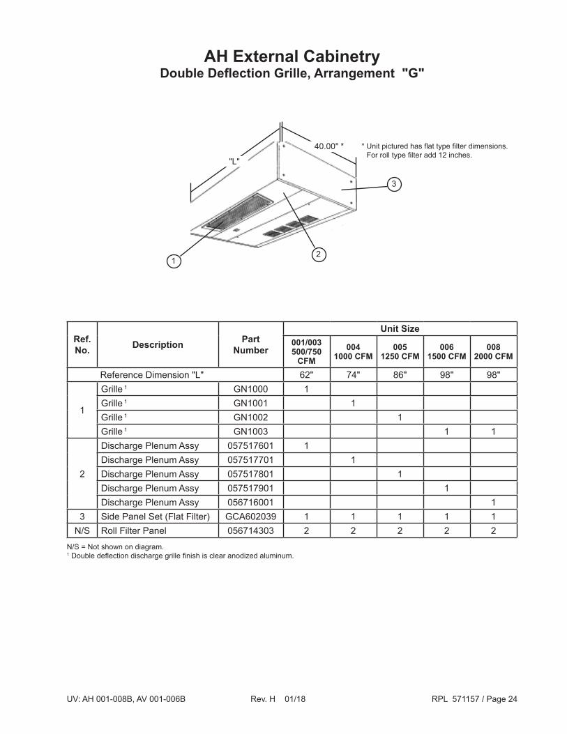
AH External CabinetryDouble Deflection Grille, Arrangement "G"
2
3
1
40.00" * * Unit pictured has flat type filter dimensions. For roll type filter add 12 inches.
N/S = Not shown on diagram.1 Double deflection discharge grille finish is clear anodized aluminum.
"L"
Ref.No. Description Part
Number
Unit Size001/003500/750
CFM004
1000 CFM005
1250 CFM006
1500 CFM008
2000 CFM
Reference Dimension "L" 62" 74" 86" 98" 98"
1
Grille 1 GN1000 1Grille 1 GN1001 1Grille 1 GN1002 1Grille 1 GN1003 1 1
2
Discharge Plenum Assy 057517601 1Discharge Plenum Assy 057517701 1Discharge Plenum Assy 057517801 1Discharge Plenum Assy 057517901 1Discharge Plenum Assy 056716001 1
3 Side Panel Set (Flat Filter) GCA602039 1 1 1 1 1N/S Roll Filter Panel 056714303 2 2 2 2 2

UV: AH 001-008B, AV 001-006B Rev. H 01/18 RPL 571157 / Page 25
AH External CabinetryBar Stock Grille w/Side Deflection Vanes, Arrangement "H"
"L"
36.00" *
1
* Unit pictured has flat type filter dimension. For roll type filter add 12".
3
2
Ref.No. Description Part
Number
Unit Size001/003500/750
CFM004
1000 CFM005
1250 CFM006
1500 CFM008
2000 CFM
Reference Dimension "L" 62" 74" 86" 98" 98"
1
Bar Grille GXF1037 1Bar Grille GXF1038 1Bar Grille GXF1039 1Bar Grille GXF1040 1 1
2
Discharge Plenum Assy 056715201 1Discharge Plenum Assy 056715202 1Discharge Plenum Assy 056715203 1Discharge Plenum Assy 056715204 1Discharge Plenum Assy 056715201 1
3 Side Panel Set (Flat Filter) GCA602038 1 1 1 1 1N/S Roll Filter Panel 056714301 2 2 2 2 2
N/S = Not shown on diagram.
UV: AH 001-008B, AV 001-006B Rev. H 01/18 RPL 571157 / Page 26
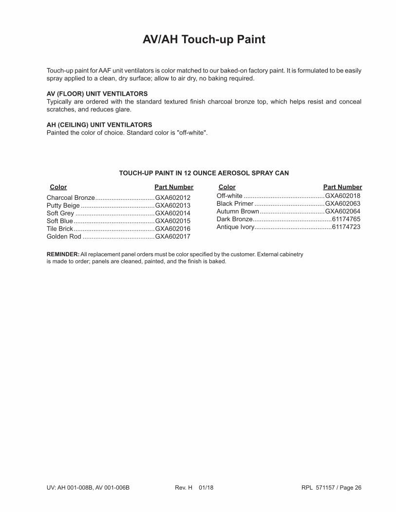
Charcoal Bronze .................................GXA602012 Putty Beige .........................................GXA602013 Soft Grey ............................................GXA602014 Soft Blue .............................................GXA602015 Tile Brick .............................................GXA602016 Golden Rod ........................................GXA602017
TOUCH-UP PAINT IN 12 OUNCE AEROSOL SPRAY CAN
Off-white .............................................GXA602018 Black Primer .......................................GXA602063 Autumn Brown ....................................GXA602064 Dark Bronze............................................61174765 Antique Ivory...........................................61174723
Color Part NumberColor Part Number
AV/AH Touch-up Paint
Touch-up paint for AAF unit ventilators is color matched to our baked-on factory paint. It is formulated to be easily spray applied to a clean, dry surface; allow to air dry, no baking required.
AV (FLOOR) UNIT VENTILATORSTypically are ordered with the standard textured finish charcoal bronze top, which helps resist and conceal scratches, and reduces glare.
AH (CEILING) UNIT VENTILATORSPainted the color of choice. Standard color is "off-white".
REMINDER: All replacement panel orders must be color specified by the customer. External cabinetry is made to order; panels are cleaned, painted, and the finish is baked.

UV: AH 001-008B, AV 001-006B Rev. H 01/18 RPL 571157 / Page 27
N/S = Not shown on diagram.NOTE: Do not mix plastic & aluminum wheels on same unit.
12
11
14
Left-hand Partition
110
9
1314
5
41
Left-hand Partition
13
SLEEVE BEARING BALL BEARING
8
67
Fan Section AV/AH Bearing Components
Ref.No. Description Part
Number
Unit Size001/003500/750
CFM
0041000 CFM
0051250 CFM
0061500 CFM
0082000 CFM
1
Fan Shaft GC8504 1Fan Shaft GC8505 1Fan Shaft GC8506 1Fan Shaft GC10116 1 1
N/S Fan Wheel- Plastic 4MFC8755 3 4 5 6 4N/S Fan Housing GCF5140 3 4 5 6 44 Sleeve Bearing, 1.25" Bore 4ACE2556A 1 1 1 1 15 Mounting Plate, Sleeve Bearing GC10138 1 1 1 1 16 Screw, Bearing to Mount Plate 4SAA505 2 2 2 2 27 Tinnerman Nut 4NKE4 4 4 4 4 48 Screw, Bulkhead to Mount Plate 046093802 4 4 4 4 49 Ball Bearing, 1.25" 4AAE7976 1 1 1 1 1
10 Mount Plate, Ball Bearing GC11186 1 1 1 1 111 Support Plate, Ball Bearing GC11187 1 1 1 1 112 Screw, Bearing to Mount Plate 4SBA4206 2 2 2 2 2
13Lockwasher, Sleeve Brg Mount 4WBC160 2 2 2 2 2Lockwasher, Ball Bearing Mount 4WBA70 2 2 2 2 2
14 Nut, Bearing Mount Plate 4NAA164 2 2 2 2 2

UV: AH 001-008B, AV 001-006B Rev. H 01/18 RPL 571157 / Page 28
Fan SectionAV/AH Motor Components
NOTE: All motors 115V-60-1 regardless of unit power supply. Care should be taken when selecting the correct replacement (X1) transformer.
Ref.No. Description Part
Number
Unit Size001/003500/750
CFM
0041000 CFM
0051250 CFM
0061500 CFM
0082000 CFM
10 Gasket, Motor 105622201 1 1 1 1 115 Spacer, Motor GC12271 1 1 1 1 1
16Bolt, Motor Mount Assy- 1/8HP 056608701 2 2 2 2 2Bolt, Motor Mount Assy- 1/4HP 056608702 2 2 2 2 2Bolt, Motor Mount Assy- 1/2HP 056608703 2 2 2 2 2
17Coupling, Motor to Shaft GCA500015A 1 1 1 1 1Set Screw 4SDL2239A 3 3 3 3 3
18
Sleeve Bearing Motor, 1/8 HP HAEQ5934 1 1 1 1 1Sleeve Bearing Motor, 1/4 HP 057076501 1 1 1 1 1Ball Bearing Motor, 1/8 HP HAEQ5935B 1 1 1 1 1Ball Bearing Motor, 1/4 HP JADQ5937 1 1 1 1 1Ball Bearing Motor, 1/3 HP 107654201 1 1 1 1 1Ball Bearing Motor, 1/2 HP LADQ5949 1 1 1 1 1
UV: AH 001-008B, AV 001-006B Rev. H 01/18 RPL 571157 / Page 29
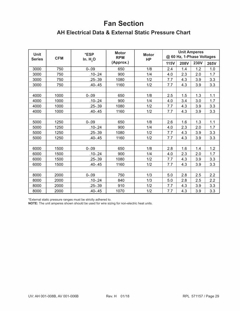
Fan SectionAH Electrical Data & External Static Pressure Chart
3000 750 0-.09 650 1/8 2.4 1.4 1.2 1.0 3000 750 .10-.24 900 1/4 4.0 2.3 2.0 1.7 3000 750 .25-.39 1080 1/2 7.7 4.3 3.9 3.3 3000 750 .40-.45 1160 1/2 7.7 4.3 3.9 3.3
4000 1000 0-.09 650 1/8 2.5 1.5 1.3 1.1 4000 1000 .10-.24 900 1/4 4.0 3.4 3.0 1.7 4000 1000 .25-.39 1080 1/2 7.7 4.3 3.9 3.3 4000 1000 .40-.45 1160 1/2 7.7 4.3 3.9 3.3
5000 1250 0-.09 650 1/8 2.6 1.6 1.3 1.1 5000 1250 .10-.24 900 1/4 4.0 2.3 2.0 1.7 5000 1250 .25-.39 1080 1/2 7.7 4.3 3.9 3.3 5000 1250 .40-.45 1160 1/2 7.7 4.3 3.9 3.3
6000 1500 0-.09 650 1/8 2.8 1.6 1.4 1.2 6000 1500 .10-.24 900 1/4 4.0 2.3 2.0 1.7 6000 1500 .25-.39 1080 1/2 7.7 4.3 3.9 3.3 6000 1500 .40-.45 1160 1/2 7.7 4.3 3.9 3.3 8000 2000 0-.09 750 1/3 5.0 2.8 2.5 2.2 8000 2000 .10-.24 840 1/3 5.0 2.8 2.5 2.2 8000 2000 .25-.39 910 1/2 7.7 4.3 3.9 3.3 8000 2000 .40-.45 1070 1/2 7.7 4.3 3.9 3.3
265V230V208V115V
MotorHP
MotorRPM
(Approx.)
UnitSeries
Unit Amperes@ 60 Hz, 1-Phase Voltages*ESP
In. H2OCFM
*External static pressure ranges must be strictly adhered to.NOTE: The unit amperes shown should be used for wire sizing for non-electric heat units.
UV: AH 001-008B, AV 001-006B Rev. H 01/18 RPL 571157 / Page 30
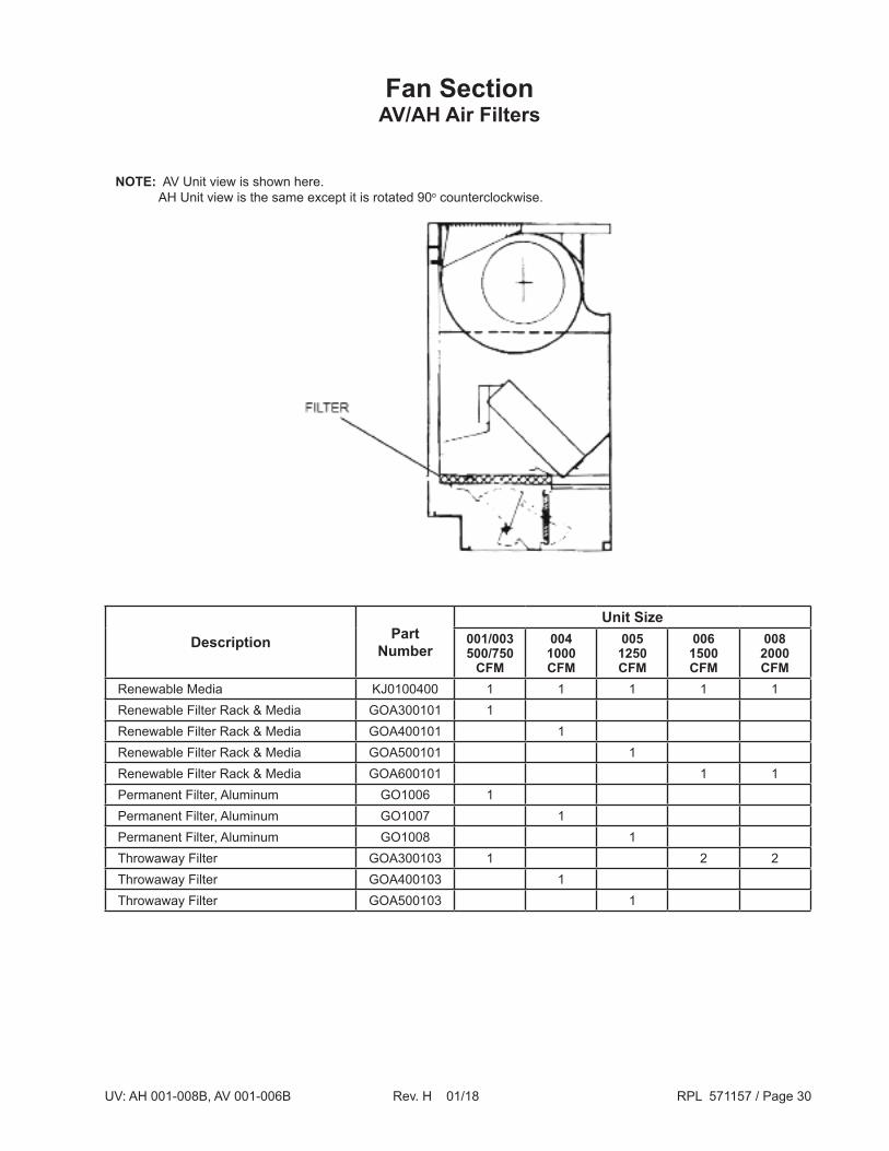
Fan SectionAV/AH Air Filters
NOTE: AV Unit view is shown here. AH Unit view is the same except it is rotated 90o counterclockwise.
Description PartNumber
Unit Size001/003500/750
CFM
0041000 CFM
0051250 CFM
0061500 CFM
0082000 CFM
Renewable Media KJ0100400 1 1 1 1 1Renewable Filter Rack & Media GOA300101 1Renewable Filter Rack & Media GOA400101 1Renewable Filter Rack & Media GOA500101 1Renewable Filter Rack & Media GOA600101 1 1Permanent Filter, Aluminum GO1006 1Permanent Filter, Aluminum GO1007 1Permanent Filter, Aluminum GO1008 1Throwaway Filter GOA300103 1 2 2Throwaway Filter GOA400103 1Throwaway Filter GOA500103 1

UV: AH 001-008B, AV 001-006B Rev. H 01/18 RPL 571157 / Page 31
AV/AH Damper Section AV Drain Pan & Coil Frame Blockoff Diagrams

UV: AH 001-008B, AV 001-006B Rev. H 01/18 RPL 571157 / Page 32
AV/AH Damper SectionAH Drain Pan & Coil Frame Blockoff Diagrams
UV: AH 001-008B, AV 001-006B Rev. H 01/18 RPL 571157 / Page 33
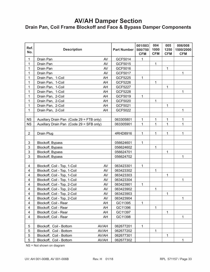
1 Drain Pan AV GCF5014 1 1 Drain Pan AV GCF5015 1 1 Drain Pan AV GCF5016 1 1 Drain Pan AV GCF5017 1 1 Drain Pan, 1-Coil AH GCF5225 1 1 Drain Pan, 1-Coil AH GCF5226 1 1 Drain Pan, 1-Coil AH GCF5227 1 1 Drain Pan, 1-Coil AH GCF5228 1 1 Drain Pan, 2-Coil AH GCF5019 1 1 Drain Pan, 2-Coil AH GCF5020 1 1 Drain Pan, 2-Coil AH GCF5021 1 1 Drain Pan, 2-Coil AH GCF5022 1
NS Auxillary Drain Pan (Code 29 = FTB only) 063305801 1 1 1 1 NS Auxillary Drain Pan (Code 29 = SFB only) 063305901 1 1 1 1
2 Drain Plug 4RHD8916 1 1 1 1
3 Blockoff, Bypass 056624601 1 3 Blockoff, Bypass 056624602 1 3 Blockoff, Bypass 056624701 1 3 Blockoff, Bypass 056624702 1
4 Blockoff, Coil - Top, 1-Coil AV 063423301 1 4 Blockoff, Coil - Top, 1-Coil AV 063423302 1 4 Blockoff, Coil - Top, 1-Coil AV 063423303 1 4 Blockoff, Coil - Top, 1-Coil AV 063423304 1 4 Blockoff, Coil - Top, 2-Coil AV 063423901 1 4 Blockoff, Coil - Top, 2-Coil AV 063423902 1 4 Blockoff, Coil - Top, 2-Coil AV 063423903 1 4 Blockoff, Coil - Top, 2-Coil AV 063423904 1 4 Blockoff, Coil - Rear AH GC11395 1 4 Blockoff, Coil - Rear AH GC11396 1 4 Blockoff, Coil - Rear AH GC11397 1 4 Blockoff, Coil - Rear AH GC11398 1
5 Blockoff, Coil - Bottom AV/AH 062677201 1 5 Blockoff, Coil - Bottom AV/AH 062677202 1 5 Blockoff, Coil - Bottom AV/AH 062677301 1 5 Blockoff, Coil - Bottom AV/AH 062677302 1
006/0081500/2000
CFM
0051250CFM
0041000CFM
001/003500/750
CFMPart NumberDescriptionRef.
No.
AV/AH Damper SectionDrain Pan, Coil Frame Blockoff and Face & Bypass Damper Components
NS = Not shown on diagram

UV: AH 001-008B, AV 001-006B Rev. H 01/18 RPL 571157 / Page 34
AV/AH Damper SectionDrain Pan, Coil Frame Blockoff and Face & Bypass Damper Components,
Cont'd.
N/A = Not Applicable
6 Damper Stop, Front GC11690 1 6 Damper Stop, Front GC11691 1 6 Damper Stop, Front GC11692 1 6 Damper Stop, Front GC11693 1
7 Damper Stop, Rear 106011701 1 7 Damper Stop, Rear 106011801 1 7 Damper Stop, Rear 106011901 1 7 Damper Stop, Rear 106012001 1
8 Blockoff, Coil GC10564 2 2 2 2
9 Partition, RH GCF5706 1 1 1 1 10 Partition, LH GCF5707 1 1 1 1 10 Partition, LH - Electric Heat / CW Only GCF5710 1 1 1 1 10 Partition, LH - Electric Heat / DX Only GCF5711 1 1 1 1
20 Screw 4SBA2164 32 32 32 3 2 21 Screw - Crankarm to End 4SBA2580 4 4 4 4 22 Tinnerman Nut 802017079 4 4 4 4 23 Mohair BY0010100 0.8 FT. 0.8 FT. 0.8 FT. 0.8 FT. 24 Adhesive (Ref.) KK02601 1 1 1 1
26 Screw - Crankarm to Counterweight 4SAC2799 1 2 2 2 27 Crankarm - To Counterweight Screw 4NAA355 1 2 2 2
31 Damper Bearing, Nylon 4ACN1491 2 2 2 2 32 Lockwasher 4WBA237 1 2 2 2
36 Shaft, Damper GC10747 1 1 1 1 37 End GC10044 2 2 2 2
38 Counterweight GC10744 N/A 2 1 N/A 39 Counterweight GC10745 1 N/A 1 2
40 Damper GCF5002 1 40 Damper GCF5003 1 40 Damper GCF5004 1 40 Damper GCF5005 1
41 Crankarm GCF5203 1 2 2 2
006/0081500/2000
CFM
0051250CFM
0041000CFM
001/003500/750
CFMPart NumberDescriptionRef.
No.

UV: AH 001-008B, AV 001-006B Rev. H 01/18 RPL 571157 / Page 35
AV/AH Damper Section Actuator
1 Actuator - OA with Linkage 4EZB9324 2 Actuator - FBP with Linkage 4EZB9324 3 Bracket - OA Actuator GE1033 4 Bracket - FBP Actuator GE1034 5 Rod - OA Damper GE1031 6 Rod - FBP Damper GE1032 7 Arm Damper 4HFZ4431 8 Swivel Connector 4HEZ1661 9 Screw 4SBA510 10 Nut 4NAA163 11 Lockwasher 048164808
Bubble Number Description Part
Number
NOTE: Adjust linkage with the outdoor air damper in closed outdoor air position, so the damper actuator is 1/16" short of its mechanical stop position.

UV: AH 001-008B, AV 001-006B Rev. H 01/18 RPL 571157 / Page 36
AV/AH Damper SectionOutdoor Air & Return Air Damper Diagrams
UV: AH 001-008B, AV 001-006B Rev. H 01/18 RPL 571157 / Page 37
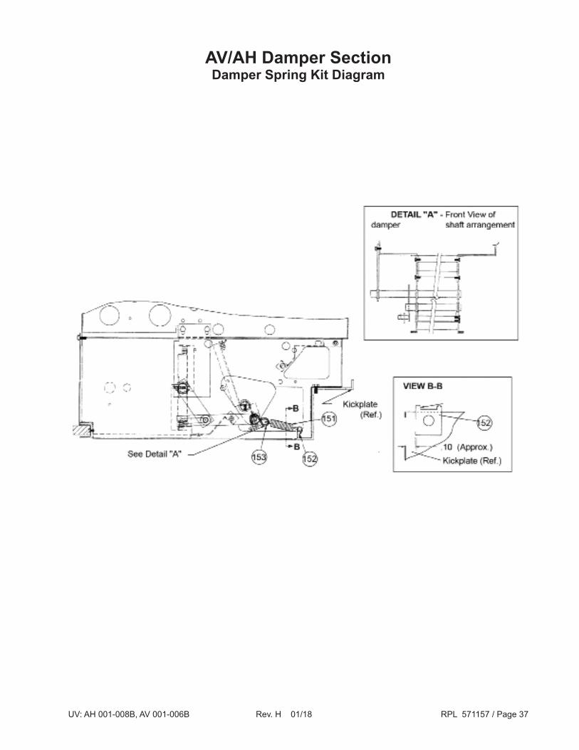
AV/AH Damper SectionDamper Spring Kit Diagram
UV: AH 001-008B, AV 001-006B Rev. H 01/18 RPL 571157 / Page 38
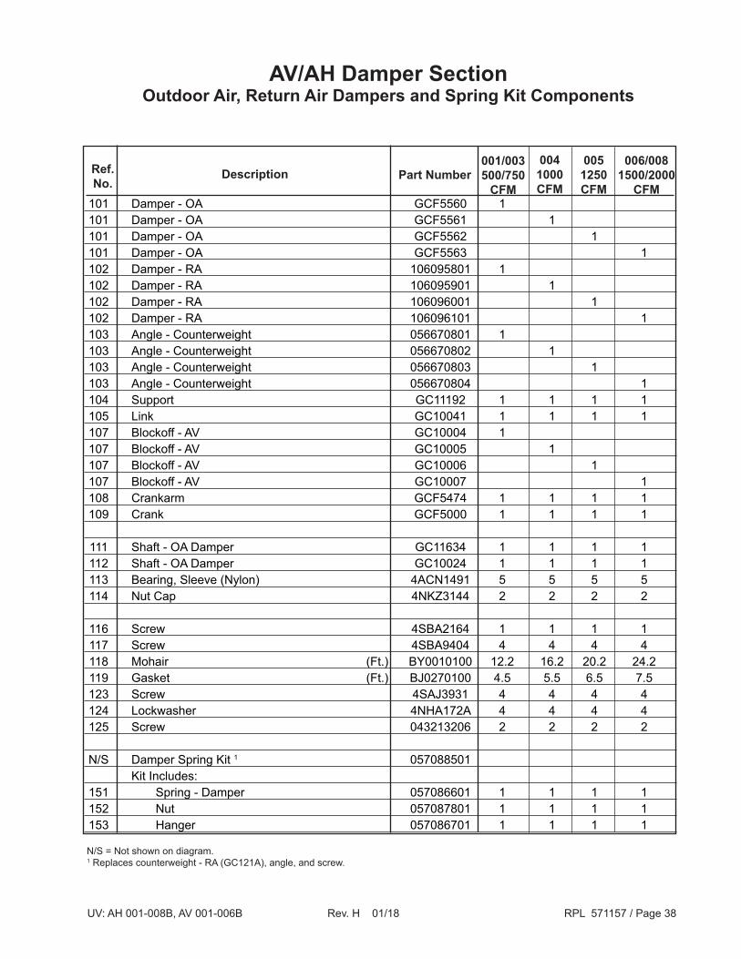
AV/AH Damper SectionOutdoor Air, Return Air Dampers and Spring Kit Components
N/S = Not shown on diagram.1 Replaces counterweight - RA (GC121A), angle, and screw.
101 Damper - OA GCF5560 1 101 Damper - OA GCF5561 1 101 Damper - OA GCF5562 1 101 Damper - OA GCF5563 1 102 Damper - RA 106095801 1 102 Damper - RA 106095901 1 102 Damper - RA 106096001 1 102 Damper - RA 106096101 1 103 Angle - Counterweight 056670801 1 103 Angle - Counterweight 056670802 1 103 Angle - Counterweight 056670803 1 103 Angle - Counterweight 056670804 1 104 Support GC11192 1 1 1 1 105 Link GC10041 1 1 1 1 107 Blockoff - AV GC10004 1 107 Blockoff - AV GC10005 1 107 Blockoff - AV GC10006 1 107 Blockoff - AV GC10007 1 108 Crankarm GCF5474 1 1 1 1 109 Crank GCF5000 1 1 1 1
111 Shaft - OA Damper GC11634 1 1 1 1 112 Shaft - OA Damper GC10024 1 1 1 1 113 Bearing, Sleeve (Nylon) 4ACN1491 5 5 5 5 114 Nut Cap 4NKZ3144 2 2 2 2
116 Screw 4SBA2164 1 1 1 1 117 Screw 4SBA9404 4 4 4 4 118 Mohair (Ft.) BY0010100 12.2 16.2 20.2 24.2 119 Gasket (Ft.) BJ0270100 4.5 5.5 6.5 7.5 123 Screw 4SAJ3931 4 4 4 4 124 Lockwasher 4NHA172A 4 4 4 4 125 Screw 043213206 2 2 2 2 N/S Damper Spring Kit 1 057088501 Kit Includes: 151 Spring - Damper 057086601 1 1 1 1 152 Nut 057087801 1 1 1 1 153 Hanger 057086701 1 1 1 1
006/0081500/2000
CFM
0051250CFM
0041000CFM
001/003500/750
CFMPart NumberDescriptionRef.
No.

UV: AH 001-008B, AV 001-006B Rev. H 01/18 RPL 571157 / Page 39
AV/AH Control Valve Components
Hot Water Valve / Actuator 24V N.O. Valve, 3-way, 1/2" Connections, #2 Port, 2.0 CV 4FAV9333 Valve, 3-way, 1/2" Connections, #4 Port, 4.0 CV 4FAV9334 Valve, 3-way, 3/4" Connections, #6 Port, 6.8 CV 4FAV9335
Steam Valve with Actuator 24V, N.O. (Straight) Valve, 2-way, 1/2" Connections, #2 Port, 1.3 CV 067182001 Valve, 2-way, 1/2" Connections, #3 Port, 2.2 CV 067182002 Valve, 2-way, 1/2" Connections, #4 Port, 3.6 CV 067182003 Valve, 2-way, 3/4" Connections, #5 Port, 5.0 CV 067182004 Valve, 2-way, 3/4" Connections, #6 Port, 6.2 CV 067182005 Valve, 2-way, 1" Connections, #7 Port, 8.2 CV 067182006 Valve, 2-way, 1" Connections, #8 Port, 11.0 CV 067182007
Chilled Water Valve / Actuator 24V N.C. Valve, 3-way, 1/2" Connections, #1 Port, 2.0 CV 4FAV9333 Valve, 3-way, 1/2" Connections, #4 Port, 4.0 CV 4FAV9334 Valve, 3-way, 3/4" Connections, #6 Port, 6.8 CV 4FAV9335
2-Pipe Chilled / Hot Water use N.O. Valves (Straight)
End-of-Cycle Valves with FBP Damper Valve, 2-way, 1" Connections, Straight, 8.0 CV 4FDV7958 Valve, 3-way, 1" Connections, Straight, 6.7 CV 4FDV7959 Valve, 3-way, 3/4" Connections, 5.4 CV 057538301
Actuator Only - 24V 056610701 Fitting, Elbow Street 90°,1/2", To adapt straight to angle configuration 067185301
Description Part Number

UV: AH 001-008B, AV 001-006B Rev. H 01/18 RPL 571157 / Page 40
AV/AH Coil SectionCoils
Hot Water Coil - Hot Water, Low Capacity, 1-row N/A 107691901 56953742 56953743 56953744 Coil - Hot Water, Med. Capacity, 2-row N/A 56953701 56953702 56953703 56953704 Chilled Water / Hot Water * Coil - Chilled Water, 3-row N/A 56953711 56953712 56953713 56953714 Coil - Chilled Water, 4-row N/A 56953721 56953723 56953725 56953727 Coil - Chilled Water, 5-row N/A 56953731 56953732 56953733 56953734
Steam ** Coil - Steam,Low Capacity, 1-row N/A GRF1013 GRF1014 GRF1015 GRF1016 Coil - Steam, High Capacity, 2-row N/A GRF1000 GRF1001 GRF1002 GRF1003 Check Valve N/A 37520002 37520002 37520002 37520002 Direct Expansion Coil - Direct Expansion 57055801 56666702 56666701 56666601 56666602 Coil - Direct Expansion, Heat Pump N/A 56666702 56666701 56666601 56666602 Expansion Valve 4FDV8931 56662904 56662904 56662902 56662905 Check Valve (heat pump coil) N/A 37520002 37520002 37520002 37520002 Channel, Coil Support - Part Number 56958701
Screw - Part Number 4SBA4206
Description
N/A = Not Applicable* Reference Instructions - Hot Water Coil Mounting - 57053201.
** Reference Instructions - Cold Water Coil Mounting - 57053101.
006/0081500/2000
CFM
0051250CFM
0041000CFM
001500CFM
003750CFM
Channel, Coil SupportScrew
UV: AH 001-008B, AV 001-006B Rev. H 01/18 RPL 571157 / Page 41
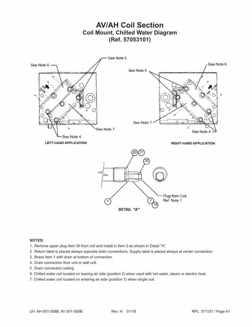
AV/AH Coil SectionCoil Mount, Chilled Water Diagram
(Ref. 57053101)
NOTES:1. Remove upper plug Item 30 from coil and install in Item 2 as shown in Detail "A".2. Return label is placed always opposite drain connections. Supply label is placed always at center connection.3. Braze Item 1 with drain at bottom of connection.4. Drain connection floor unit or wall unit.5. Drain connection ceiling.6. Chilled water coil located on leaving air side (position 2) when used with hot water, steam or electric heat.7. Chilled water coil located on entering air side (position 1) when single coil.

UV: AH 001-008B, AV 001-006B Rev. H 01/18 RPL 571157 / Page 42
AV/AH Coil SectionCoil Mount, Hot Water Diagram
(Ref. 57053201)
NOTES:1. Remove upper plug Item 30 from coil and install in Item 2 as shown in Detail "A".2. Return label is placed always opposite drain connections. Supply label is placed always at center connection.3. Braze Item 1 with drain at bottom of connection.4. Drain connection floor unit or wall unit.5. Drain connection ceiling.6. Hot water coil located on leaving air side (position 2) when used with direct expansion coil.7. Hot water coil located on entering air side (position 1) when single coil or with chilled water coil.
UV: AH 001-008B, AV 001-006B Rev. H 01/18 RPL 571157 / Page 43
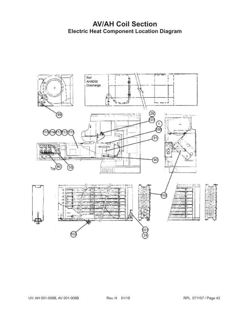
AV/AH Coil SectionElectric Heat Component Location Diagram

UV: AH 001-008B, AV 001-006B Rev. H 01/18 RPL 571157 / Page 44
Part NumberBub.No.
Ref.No. Description
80 C1/C11 Relay, Operating and Backup with Mounting Ears 4EWJ8799 89 AF Switch, Airflow - AH8000 only 4EMB8125
90 DF Switch, Deadfront 4EAL2427
91 SW1 Switch, Main Power Disconnect - 100 amp 4EUL6509A 91 SW1 Switch, Main Power Disconnect - 225 amp 4EVQ6319
101 OH1 Thermostat, Overheat AV/AH 1 4ELN7697
102 OH2 Thermostat, Overheat AH only 4ELN5523
AV/AH Coil SectionElectric Heat Components
1 Overheat stat OH1 moved per PC8752; effective 12-16-84; see drawing on previous page.
Ref. Total Qty. Elements 2 3 4 5 6 7 8 9 Relays 2 3 3 3 3 4 5 6

UV: AH 001-008B, AV 001-006B Rev. H 01/18 RPL 571157 / Page 45
AV/AH Coil SectionElectric Heat Section
Sheathed
110 HTR 1/9 Element 208 4EHH8887 4EHH8888 4EHH8889 4EHH8890 112 F2A/F6C Fuseblock, 30 Amp 208 4EHC8870 4EHC8870 4EHC8870 4EHC8870 113 F2A/F6C Fuseblock, 60 Amp 208 4EHC4506 4EHC4506 4EHC4506 4EHC4506 114 F2A/F6C Fuse, 30 Amp 208 4EHG1979 4EHG1979 4EHG1979 4EHG1979 115 F2A/F6C Fuse, 60 Amp 208 4EHG4083 4EHG4083 4EHG4083 4EHG4083
110 HTR 1/9 Element 230 4EHH8891 4EHH8892 4EHH8893 4EHH8894 112 F2A/F6C Fuseblock, 30 Amp 230 4EHG8870 N/A N/A 4EHG8870 113 F2A/F6C Fuseblock, 60 Amp 230 4EHC7700 4EHC7700 4EHC7700 4EHC7700 114 F2A/F6C Fuse, 30 Amp 230 4EHG1979 N/A 4EHG1979 4EHG1979 115 F2A/F6C Fuse, 60 Amp 230 4EHG4083 4EHG4083 4EHG4083 4EHG4083
110 HTR 1/9 Element 265 063414501 063414502 063414503 063414504 111 TB Terminal Block 265 802007686 N/A N/A N/A 112 F2A/F6C Fuseblock, 30 Amp 265 N/A 4EHC8870 N/A 4EHC8870 113 F2A/F6C Fuseblock, 60 Amp 265 N/A 4EHC4506 4EHC4506 4EHC4506 114 F2A/F6C Fuse, 30 Amp 265 N/A 4EHG1979 4EHG1979 4EHG1979 115 F2A/F6C Fuse, 60 Amp 265 N/A 4EHG4083 4EHG4083 4EHG4083 110 HTR 1/9 Element 460 4EHH8895 4EHH8896 4EHH8897 4HEH8898 111 TB Terminal Block 460 802007686 802007686 802007686 802007686
110 HTR 1/9 Element 575 4EHH8899 4EHH8900 4EHH8901 4EHH8902 111 TB Terminal Block 575 802007686 802007686 802007686 802007686
Ref.No.
Unit Size
Sch.No. Description Voltage
N/A = Not Applicable
006/0081500/2000
CFM
0051250CFM
0041000CFM
001/003500/750
CFM
UV: AH 001-008B, AV 001-006B Rev. H 01/18 RPL 571157 / Page 46
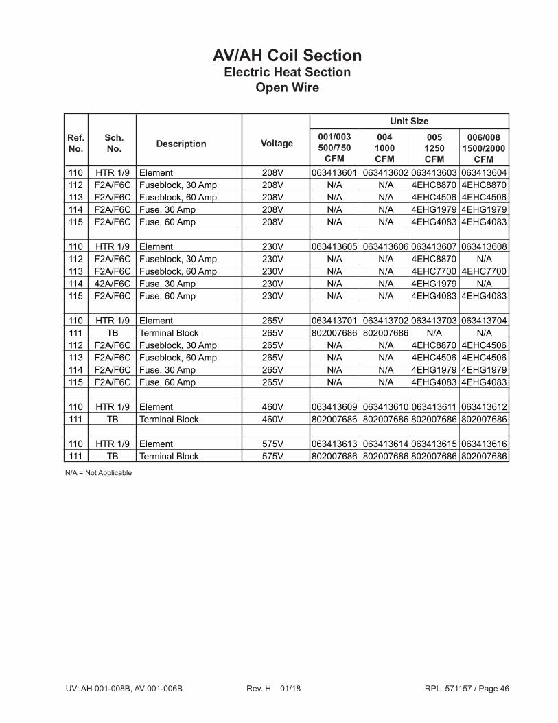
AV/AH Coil SectionElectric Heat Section
Open Wire
110 HTR 1/9 Element 208V 063413601 063413602 063413603 063413604 112 F2A/F6C Fuseblock, 30 Amp 208V N/A N/A 4EHC8870 4EHC8870 113 F2A/F6C Fuseblock, 60 Amp 208V N/A N/A 4EHC4506 4EHC4506 114 F2A/F6C Fuse, 30 Amp 208V N/A N/A 4EHG1979 4EHG1979 115 F2A/F6C Fuse, 60 Amp 208V N/A N/A 4EHG4083 4EHG4083 110 HTR 1/9 Element 230V 063413605 063413606 063413607 063413608 112 F2A/F6C Fuseblock, 30 Amp 230V N/A N/A 4EHC8870 N/A 113 F2A/F6C Fuseblock, 60 Amp 230V N/A N/A 4EHC7700 4EHC7700 114 42A/F6C Fuse, 30 Amp 230V N/A N/A 4EHG1979 N/A 115 F2A/F6C Fuse, 60 Amp 230V N/A N/A 4EHG4083 4EHG4083
110 HTR 1/9 Element 265V 063413701 063413702 063413703 063413704 111 TB Terminal Block 265V 802007686 802007686 N/A N/A 112 F2A/F6C Fuseblock, 30 Amp 265V N/A N/A 4EHC8870 4EHC4506 113 F2A/F6C Fuseblock, 60 Amp 265V N/A N/A 4EHC4506 4EHC4506 114 F2A/F6C Fuse, 30 Amp 265V N/A N/A 4EHG1979 4EHG1979 115 F2A/F6C Fuse, 60 Amp 265V N/A N/A 4EHG4083 4EHG4083
110 HTR 1/9 Element 460V 063413609 063413610 063413611 063413612 111 TB Terminal Block 460V 802007686 802007686 802007686 802007686 110 HTR 1/9 Element 575V 063413613 063413614 063413615 063413616 111 TB Terminal Block 575V 802007686 802007686 802007686 802007686
Ref.No.
Unit Size
VoltageSch.No. Description
N/A = Not Applicable
006/0081500/2000
CFM
0051250CFM
0041000CFM
001/003500/750
CFM

UV: AH 001-008B, AV 001-006B Rev. H 01/18 RPL 571157 / Page 47
AV/AH ControlsMicroTech Diagram

UV: AH 001-008B, AV 001-006B Rev. H 01/18 RPL 571157 / Page 48
AV/AH ControlsMicroTech Components
Bub.No.
Ref.No. Description Part Number Qty.
21 UVC 125 Controller 063270001 1 21 UVC 325 Controller 073397901 1 22 N/A Bracket-Controller GE1428 1 23 N/A Hinge-Controller GE1324 2 24 S1 Sensor, Room Temperature, Unit Mtd. GEF1947 1 N/S S1 Sensor, Room Temperature, Wall Mtd. 058899301 1 N/S S1 Sensor, Room Temperature, Wall Mtd. w/TOR 1 058899311 1 N/S S1 Sensor, Room Temperature, Wall Mtd. w/SPA 2 058899321 1 N/S S1 Sensor, Room Temperature, Wall Mtd. w/TOR & SPA 1,2 058899341 1 N/S S1 Sensor, Room Temperature, Wall Mtd. Thermometer 058899302 1 N/S S1 Sensor, Room Temperature, Wall Mtd. Thermometer w/TOR 1 058899312 1 N/S S1 Sensor, Room Temperature, Wall Mtd. Thermometer w/SPA 2 058899322 1 N/S S1 Sensor, Room Temperature, Wall Mtd. Thermometer w/TOR & SPA1,2 058899342 1 N/S S1 Sensor, Room Temperature, Wall Mtd. w/Comm. Port 058899331 N/S S1 Sensor, Room Temperature, Wall Mtd. w/Therm. & Comm. Port 058899332 N/S S1 Sensor, Room Temperature, Wall Mtd. w/TOR & Comm. Port 058899351 N/S S1 Sensor, Room Temperature, Wall Mtd. w/Therm. & TOR & Comm. Port 058899352 N/S S1 Sensor, Room Temperature, Wall Mtd. w/ SPA & Comm. Port 058899361 N/S S1 Sensor, Room Temperature, Wall Mtd. w/Therm. & SPA, & Comm, Port 058899362 N/S S1 Sensor, Room Temperature, Wall Mtd. w/TOR & SPA, & Comm. Port 058899371 N/S S1 Sensor, Room Temp., Wall Mtd. w/Therm. & TOR & SPA & Comm. Port 058899372 25 N/A Bracket, Room Temp., Unit Mtd. (sampling chamber) GC11849 1 26 S2 Sensor, Discharge Air Temperature GEF1947 1 27 S3 Sensor, Outdoor Air Temperature GEF1948 1 N/S S4 Sensor, Mixed Air Temperature - 3 Fan 063297203 1 N/S S4 Sensor, Mixed Air Temperature - 4 Fan 063297204 1 N/S S4 Sensor, Mixed Air Temperature - 5 Fan 063297205 1 N/S S4 Sensor, Mixed Air Temperature - 6 Fan 063297206 1 N/S S5 Sensor, Water Temperature GEF1948 1 34 T4 Thermostat, Low Temperature, DE Coil 4ELN7604 1 36 T6 Thermostat, Low Temperature, Hydronic Coil 4ELN9178 1 56 X6 Transformer, UVC 4EPC9188 1 N/S T6 Freezestat Kit for Field Mounting 057088001 1 N/S N/A Freezestat Clip 106456801 1 N/S OH1 Thermostat, Electric Heat Overheat 4ELN5523
N/S OPT. Harness-MicroTech to PC 19900CC 1 N/S OPT. Harness-Surge Protection, UVC Network 056717101 1 N/S OPT. Harness-Surge Protection, UVC Slave 056717201 1N/A = Not ApplicableN/S = Not shown on diagram1 TOR = Tennant Override2 SPA = Setpoint Adjustment
UV: AH 001-008B, AV 001-006B Rev. H 01/18 RPL 571157 / Page 49
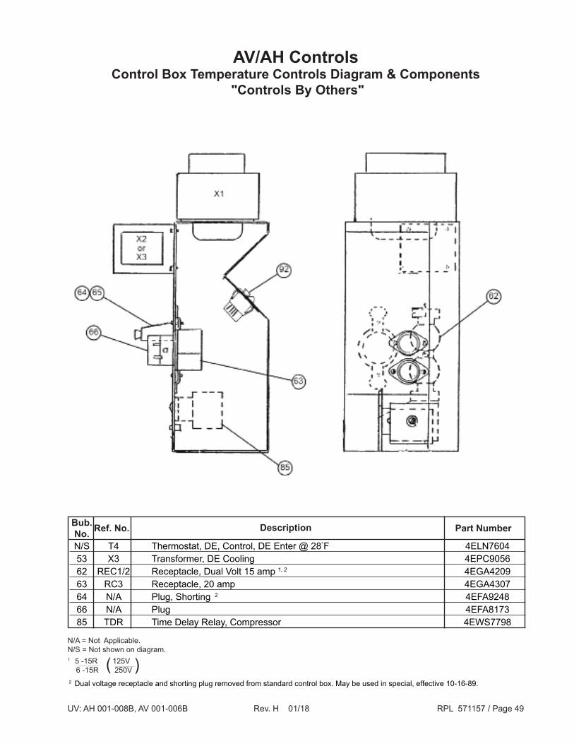
AV/AH ControlsControl Box Temperature Controls Diagram & Components
"Controls By Others"
Part NumberBub.No. DescriptionRef. No.
2 Dual voltage receptacle and shorting plug removed from standard control box. May be used in special, effective 10-16-89.
N/A = Not Applicable.N/S = Not shown on diagram.
N/S T4 Thermostat, DE, Control, DE Enter @ 28°F 4ELN7604 53 X3 Transformer, DE Cooling 4EPC9056 62 REC1/2 Receptacle, Dual Volt 15 amp 1, 2 4EGA4209 63 RC3 Receptacle, 20 amp 4EGA4307 64 N/A Plug, Shorting 2 4EFA9248 66 N/A Plug 4EFA8173 85 TDR Time Delay Relay, Compressor 4EWS7798
)(1 5 -15R 125V 6 -15R 250V

UV: AH 001-008B, AV 001-006B Rev. H 01/18 RPL 571157 / Page 50
AV/AH ControlsPrimary Control Box DiagramElectromechanical Controls
UV: AH 001-008B, AV 001-006B Rev. H 01/18 RPL 571157 / Page 51
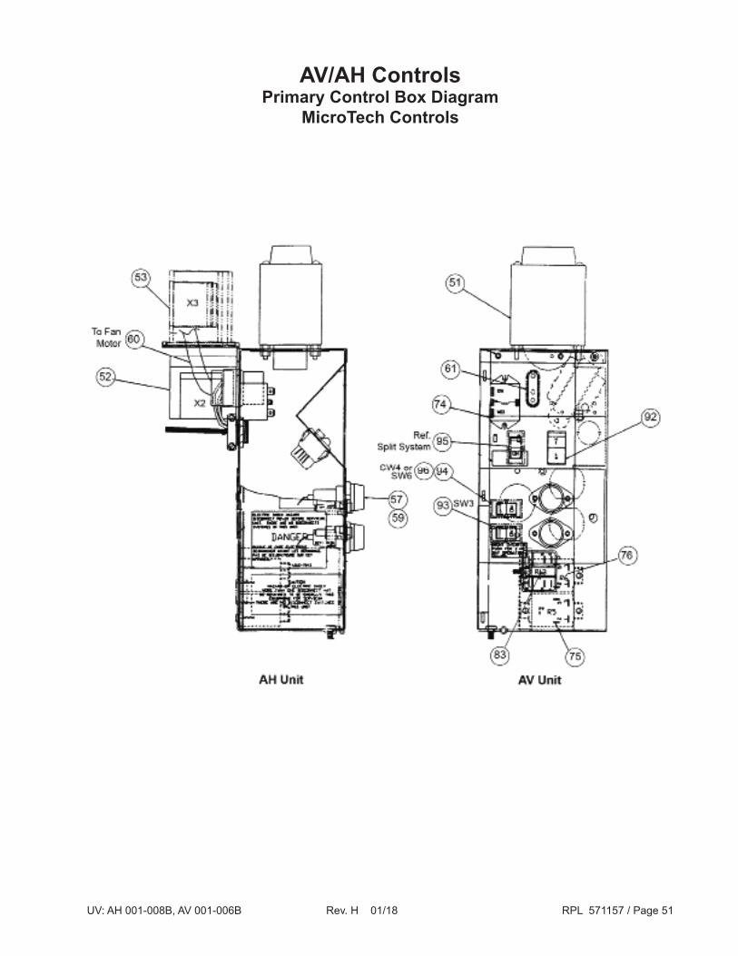
AV/AH ControlsPrimary Control Box Diagram
MicroTech Controls

UV: AH 001-008B, AV 001-006B Rev. H 01/18 RPL 571157 / Page 52
AV/AH ControlsSpecialty Component Location Diagram
UV: AH 001-008B, AV 001-006B Rev. H 01/18 RPL 571157 / Page 53
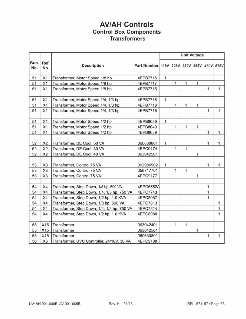
AV/AH ControlsControl Box Components
Transformers
51 X1 Transformer, Motor Speed 1/8 hp 4EPB7715 1 51 X1 Transformer, Motor Speed 1/8 hp 4EPB7717 1 1 1 51 X1 Transformer, Motor Speed 1/8 hp 4EPB7715 1 1 51 X1 Transformer, Motor Speed 1/4, 1/3 hp 4EPB7716 1 51 X1 Transformer, Motor Speed 1/4, 1/3 hp 4EPB7718 1 1 1 51 X1 Transformer, Motor Speed 1/4, 1/3 hp 4EPB7716 1 1
51 X1 Transformer, Motor Speed 1/2 hp 4EPB8039 1 51 X1 Transformer, Motor Speed 1/2 hp 4EPB8040 1 1 1 51 X1 Transformer, Motor Speed 1/2 hp 4EPB8039 1 1
52 X2 Transformer, DE Cool, 50 VA 060630801 1 1 1 52 X2 Transformer, DE Cool, 30 VA 4EPC9174 1 1 52 X2 Transformer, DE Cool, 40 VA 063042501 1 53 X3 Transformer, Control 75 VA 062986902 1 1 1 53 X3 Transformer, Control 75 VA 056717701 1 1 53 X3 Transformer, Control 75 VA 4EPC9177 1 54 X4 Transformer, Step Down, 1/8 hp, 500 VA 4EPC6552A 1 54 X4 Transformer, Step Down, 1/4, 1/3 hp, 750 VA 4EPC7743 1 54 X4 Transformer, Step Down, 1/2 hp, 1.0 KVA 4EPC8087 1 54 X4 Transformer, Step Down, 1/8 hp, 500 VA 4EPC7813 1 54 X4 Transformer, Step Down, 1/4, 1/3 hp, 750 VA 4EPC7814 1 54 X4 Transformer, Step Down, 1/2 hp, 1.0 KVA 4EPC8088 1
55 X15 Transformer 063042401 1 1 55 X15 Transformer 063042501 1 55 X15 Transformer 060630801 1 1 56 X6 Transformer, UVC Controller, 24/18V, 30 VA 4EPC9188
Bub.No. 575V460V265V230V208V115V
Unit Voltage
Part NumberRef.No. Description

UV: AH 001-008B, AV 001-006B Rev. H 01/18 RPL 571157 / Page 54
AV/AH ControlsControl Box Components
Fuses, Cordsets and Receptacles
57 X7 Fuseholder 4EHB1933
58 FC/FD Fuse, X4 Transformer, 1/8, 1/4,1/3 hp, 4.0 amp 4EHG7663 58 FC/FD Fuse, X4 Transformer, 1/2 hp, 4.0 amp 4EHG7663 58 FC/FD Fuse, X4 Transformer, 1/2 hp, 3.5 amp 4EHG7713
59 FA Fuse, 1/8 hp, 5.6 amp 4EHG7749 59 FA Fuse, 1/8 hp, 4.0 amp 4EHG7663 59 FA Fuse, 1/8 hp, 3.5 amp 4EHG7713 59 FA Fuse, 1/8 hp, 3.0 amp 4EHG7748
59 FA Fuse, 1/4, 1/3 hp, 7.0 amp 4EHG7750 59 FA Fuse, 1/4, 1/3 hp, 6.25 amp 4EHG8910 59 FA Fuse, 1/4, 1/3 hp, 4.5 amp 4EHG7664 59 FA Fuse, 1/4, 1/3 hp, 4.0 amp 4EHG7663 59 FA Fuse, 1/4, 1/3 hp, 3.5 amp 4EHG7713
59 FA Fuse, 1/3 hp, 9.0 amp 4EHG8684
59 FA Fuse, 1/2 hp, 10.0 amp 4EHG7795 59 FA Fuse, 1/2 hp, 7.0 amp 4EHG7750 59 FA Fuse, 1/2 hp, 5.0 amp 4EHG8089
60 N/A Cord Set, Motor Plug, 24" 4EFZ7630
61 N/A Cord Set, Motor Receptacle, 6" 4EGZ7629
62 N/A Receptacle, Dual Volt 1 4EGA4209
63 N/A Receptacle, DE Cool 4EGA4307
Bub.No.
Ref.No.
Description
N/A = Not Applicable1 Dual voltage receptacle was removed from standard control box, per PC 9754, effective 10-16-89. It is used in "Controls By Others" application.
Part Number

UV: AH 001-008B, AV 001-006B Rev. H 01/18 RPL 571157 / Page 55
AV/AH ControlsControl Box Components
Relays
70 N/S Relay Cover 4EQZ7834
74 R4 Fan Relay 4EWJ8505
75 R5 Night Setback Relay, 24V 4EWJ9054 75 R5 Night Setback Relay, 115V 4EWJ9053
76 R6 Vent Lockout Relay, 24V 4EWJ9054 76 R6 Vent Lockout Relay, 115V 4EWJ9053
78 R8 RVSG Valve Relay, DE Cooling 4EWJ8799
80 C1/C11 Elec. Ht. Relay Operating & Backup 4EWJ8799
83 R13 Interlock Exhaust Fan Relay, 24V 4EWJ9054 83 R13 Interlock Exhaust Fan Relay, 115V 4EWJ9053
84 TDR Time Delay Relay, Low Volt. Prot. Elec. Heat 4EWS7798
N/A = Not Applicable.N/S = Not shown on diagram.
Bub.No.
Ref.No.
Description Part Number

UV: AH 001-008B, AV 001-006B Rev. H 01/18 RPL 571157 / Page 56
AV/AH ControlsControl Box Components
Thermostats, Switches and Time Clock
90 DF Switch, Dead Front 4EAL2427 91 SW1 Switch, Disconnect, 100 amp 4EUL6509A 91 SW1 Switch, Disconnect, 225 amp 4EVQ6319 91 SW1 Switch, Unit, Non-Electric Heat 4EAL4022
N/S SW2 Switch, Fan Speed, Remote GE420A
92 SW2 Rotary Switch, 2-Pole (120V, 227V) 057543001 92 SW2 Rotary Switch, 3-Pole (208V, 230V) 057542901
93 SW3 Switch, Day-Night/TOR 4EAL7261
94 SW4 Switch, Holiday 4EAL7260
95 SW5 Switch, Emergency, Elec. Heat, Heat Pump 4EAL7261
96 SW6 Switch, Energy Conserving, Heat Pump 4EAL7759
98 TC 24 hour Time Clock with Reserve Power, 120V 4ETA9083 98 TC 24 hour Time Clock with Reserve Power 208-230V 4ETA9094
N/S Ref. Time Clock Instruction with Reserve Power GE1424
N/S Ref. Knob (Rotary Switch) 802018013
N/A = Not Applicable.N/S = Not shown on diagram.
Bub.No.
Ref.No.
Description Part Number

Call Your Local Daikin Applied Parts Distributor For All Your Parts Needs.To Locate A Distributor, Go To www.DaikinApplied.com or Call 1-800-37PARTS
Critical Daikin Applied OEM PartsAre What Your HVAC Unit Needs!
571157 Rev. H 01/2018 CPL Page 1 of 1
AAF Unit VentilatorHerman Nelson Unit Ventilator
AH 001 - 008
AV 001 - 006
Vintage B
Critical Components Unit Sizes Voltage Part Number
ControlControl Board, MicroTech 125 ALL ALL 063270001Control Board, MicroTech 325 ALL ALL 073397901
Fan Motor Motor, Sleeve Bearing, 1/8 HP 001 - 008 115/60/1 HAEQ5934Motor, Sleeve Bearing, 1/4 HP 001 - 008 115/60/1 057076501Motor, Ball Bearing, 1/8 HP 001 - 008 115/60/1 HAEQ5935BMotor, Ball Bearing, 1/4 HP 001 - 008 115/60/1 JADQ5937Motor, Ball Bearing, 1/3 HP 001 - 008 115/60/1 107654201Motor, Ball Bearing, 1/2 HP 001 - 008 115/60/1 LADQ5949
Fan Housing & Wheel Fan Housing ALL N/A GCF5140Fan Wheel, Plastic ALL N/A 4MFC8755