AADE-17-NTCE-075 Experimental Study and Modeling of Surge ...
13
Copyright 2017, AADE This paper was prepared for presentation at the 2017 AADE National Technical Conference and Exhibition held at the Hilton Houston North Hotel, Houston, Texas, April 11-12, 2017. This conference is sponsored by the American Association of Drilling Engineers. The information presented in this paper does not reflect any position, claim or endorsement made or implied by the American Association of Drilling Engineers, their officers or members. Questions concerning the content of this paper should be directed to the individual(s) listed as author(s) of this work. Abstract With increasing eccentricity, surge and swab pressures will be considerably reduced during tripping operations. Therefore, ignoring the pipe eccentricity can result in unnecessarily reduced tripping speed and thus increased operating time. This article presents a new hydraulic model that accounts for eccentricity in surge and swab pressure predictions. Moreover, it presents results of modeling and experimental studies conducted on surge and swab pressures in eccentric annuli with Herschel Buckley fluid. The model assumes close-ended pipe that moves axially at a constant speed. It approximates the flow in eccentric annulus to several hydraulically equivalent concentric annuli sectors with variable annular clearance. To validate the model, experimental investigations were carried out using a 12-ft long vertical annular (1.32” × 2”) test section. Pipe trip speed, eccentricity and test fluid formulation were varied during the investigation. Different formulations of polymer based fluids were used in the experiments. For both concentric and eccentric annuli, the comparison of experimental measurements with model predictions shows good agreement with maximum discrepancy of 14%. Furthermore, parametric study was conducted to examine the effects of well diameter ratio, eccentricity and fluid rheological properties on surge pressure. Substantial decrease in surge pressure (maximum 40% reduction) was observed with increase in eccentricity. The outcomes and findings of this study are useful to perform optimization using the hydraulic models. The optimization is essential in planning of horizontal and extended reach wells in which wellbore pressure management is very critical and no high speed telemetry is used in the well. 1. Introduction Deep-water drilling has rapidly evolved in the recent past. Current progressions in technology have ensued in more complex drilling operations (highly deviated, extended reach and horizontal wells), and results in more difficult bottomhole pressure management. Moreover, with enhanced use of technologies like slim-hole and casing while drilling and casing running operations results is excessive surge pressure conditions. Failing to identify these down-hole pressure fluctuations, it can result in drilling problems including fracturing of formation, lost circulation, kicks and blowouts. Mitigation of the problems directly results in increased budgets due to non-productive times, damages to equipment and expensive corrective actions. Hence, an accurate surge pressure model is required to effectively predict tripping and casing running speed limits. Several studies have been conducted to accurately determine surge and swab pressures to optimize tripping operations. However, most of the studies have been conducted for a concentric annulus. Eccentricity is an essential element when accounting for pressure surge in inclined wells. Few studies (Hussain and Sharif 1997) have been conducted that investigate the effects of eccentricity on pressure surge. Numerical results showed considerable (as high as 35%) reduction in surge pressure due to eccentricity. In addition, the studies were conducted considering commonly used rheology models such as: Newtonian, Bingham plastic and power law models. However, recent studies show that the yield power law (Herschel Buckley) model best describe the fluid flow characteristics of most of fluids used in drilling and completion operations. Therefore, studying flow behavior of yield power law (YPL) fluids in eccentric annulus during tripping operation is very important. This study discusses a novel steady-state model to calculate surge and swab pressures in eccentric annuli. The model uses an approximation technique that discretizes eccentric annulus into several concentric annuli sectors with varying annular clearance. Each discretized annulus is solved utilizing a set of non-linear equations. A program (Visual Basic code) was developed to solve for the non-linear equations and predict the surge pressure in eccentric annulus. In this study, experiments were performed to investigate the effects of fluid theology and eccentricity on surge AADE-17-NTCE-075 Experimental Study and Modeling of Surge and Swab Pressures in Horizontal and Inclined Wells Ruchir Srivastav, Superior Energy Services, University of Oklahoma; Ramadan Ahmed, University of Oklahoma and Arild Saasen, University of Stavanger
Transcript of AADE-17-NTCE-075 Experimental Study and Modeling of Surge ...

Copyright 2017, AADE
This paper was prepared for presentation at the 2017 AADE National Technical Conference and Exhibition held at the Hilton Houston North Hotel, Houston, Texas, April 11-12, 2017. This conference is sponsored by the American Association of Drilling Engineers. The information presented in this paper does not reflect any position, claim or endorsement made or implied by the American Association of
Drilling Engineers, their officers or members. Questions concerning the content of this paper should be directed to the individual(s) listed as author(s) of this work.
Abstract With increasing eccentricity, surge and swab pressures will be
considerably reduced during tripping operations. Therefore,
ignoring the pipe eccentricity can result in unnecessarily
reduced tripping speed and thus increased operating time. This
article presents a new hydraulic model that accounts for
eccentricity in surge and swab pressure predictions. Moreover,
it presents results of modeling and experimental studies
conducted on surge and swab pressures in eccentric annuli
with Herschel Buckley fluid. The model assumes close-ended
pipe that moves axially at a constant speed. It approximates
the flow in eccentric annulus to several hydraulically
equivalent concentric annuli sectors with variable annular
clearance. To validate the model, experimental investigations
were carried out using a 12-ft long vertical annular (1.32” ×
2”) test section. Pipe trip speed, eccentricity and test fluid
formulation were varied during the investigation. Different
formulations of polymer based fluids were used in the
experiments.
For both concentric and eccentric annuli, the comparison
of experimental measurements with model predictions shows
good agreement with maximum discrepancy of 14%.
Furthermore, parametric study was conducted to examine the
effects of well diameter ratio, eccentricity and fluid
rheological properties on surge pressure. Substantial decrease
in surge pressure (maximum 40% reduction) was observed
with increase in eccentricity. The outcomes and findings of
this study are useful to perform optimization using the
hydraulic models. The optimization is essential in planning of
horizontal and extended reach wells in which wellbore
pressure management is very critical and no high speed
telemetry is used in the well.
1. Introduction Deep-water drilling has rapidly evolved in the recent past.
Current progressions in technology have ensued in more
complex drilling operations (highly deviated, extended reach
and horizontal wells), and results in more difficult bottomhole
pressure management. Moreover, with enhanced use of
technologies like slim-hole and casing while drilling and
casing running operations results is excessive surge pressure
conditions. Failing to identify these down-hole pressure
fluctuations, it can result in drilling problems including
fracturing of formation, lost circulation, kicks and blowouts.
Mitigation of the problems directly results in increased
budgets due to non-productive times, damages to equipment
and expensive corrective actions. Hence, an accurate surge
pressure model is required to effectively predict tripping and
casing running speed limits.
Several studies have been conducted to accurately
determine surge and swab pressures to optimize tripping
operations. However, most of the studies have been
conducted for a concentric annulus.
Eccentricity is an essential element when accounting for
pressure surge in inclined wells. Few studies (Hussain and
Sharif 1997) have been conducted that investigate the effects
of eccentricity on pressure surge. Numerical results showed
considerable (as high as 35%) reduction in surge pressure due
to eccentricity. In addition, the studies were conducted
considering commonly used rheology models such as:
Newtonian, Bingham plastic and power law models.
However, recent studies show that the yield power law
(Herschel Buckley) model best describe the fluid flow
characteristics of most of fluids used in drilling and
completion operations. Therefore, studying flow behavior of
yield power law (YPL) fluids in eccentric annulus during
tripping operation is very important.
This study discusses a novel steady-state model to
calculate surge and swab pressures in eccentric annuli. The
model uses an approximation technique that discretizes
eccentric annulus into several concentric annuli sectors with
varying annular clearance. Each discretized annulus is solved
utilizing a set of non-linear equations. A program (Visual
Basic code) was developed to solve for the non-linear
equations and predict the surge pressure in eccentric annulus.
In this study, experiments were performed to investigate
the effects of fluid theology and eccentricity on surge
AADE-17-NTCE-075
Experimental Study and Modeling of Surge and Swab Pressures in Horizontal and Inclined Wells Ruchir Srivastav, Superior Energy Services, University of Oklahoma; Ramadan Ahmed, University of Oklahoma and Arild Saasen, University of Stavanger

2 R. Srivastav, R. Ahmed and A. Saasen AADE-17-NTCE-075
pressure. Tests were conducted using a setup that has casing as
a 2-inch polycarbonate tube and the inner drillstring was a
1.32-inch steel pipe, having a stroke length of 67 inches. The
pipe trip speed was varied to measure surge pressure in both
concentric and eccentric annuli. Two polymers (Polyanionic
Cellulose and Xanthan gum) were used to prepare test fluids.
For both concentric and eccentric annuli, the comparison of
experimental measurements with model predictions shows
good agreement (maximum discrepancy of 14 %). The effects
of tripping speeds, diameter ratios, fluid viscosity and
eccentricity on surge pressure were measured as a parametric
study and concluded that these variables significantly affect
the downhole pressure variations. Experimental results
showed substantial decrease in surge pressure (maximum 40%
reduction) with increase in eccentricity.
2. Literature Review Early laboratory and field studies related with surge and swab
pressures have been as early as the 1930’s, associated with
wellbore problems (Cannon 1934; Horn 1950; Goins et al.
1951) like formation fracture, kick, lost circulation due to
pressure variations during tripping operations. In early second
half of the 20th
century few studies attempted to explain the
causes of surge and swab pressures. Some studies utilized
quantitative techniques to predict pressure variations
downhole accounting for only the viscous drag and stationary
pipe wall (Cardwell 1953; Ormsby 1954) for Newtonian fluids
in both laminar and turbulent flow regimes. Field or recorded
pressure is often unavailable; however, few analysis have
gathered relevant (Fig. 1) data (Burkhardt 1961; Ramsey et al.
1983; Wagner et al. 1993; White et al. 1997) to confirm
downhole pressure variations.
Figure 1: Surge and swab pressures while lowering a casing joint
(re-drawn from Burkhardt 1961)
3. Existing Models Numerous models with continuous advancements to account
for all possible consequences that add to pressure variations
downhole have been made, to predict these deviations as
accurately as possible. Early models were steady state and
were only valid for pressure losses in a static pipe due to
viscous forces. Models for Bingham Plastic (Clark 1955;
Burkhardt 1961; Clark and Fontenot 1974) and Power law
fluids (Schuh 1964) were also developed and accounted for
pipe movements. These models were developed considering
concentric annular geometry and a close ended drillstring. The
developed models were enhanced and implemented into
computer programs (Clark and Fontenot 1974).
More recent models accounted for the hydraulic aspect of
annular flow with axial inner pipe movement (Chukwu and
Blick 1989; Haige and Xishneg 1996; Filip and David 2003).
With limitations, many analytical solutions (Malik and Shenoy
1991) and numerical procedures (Lin and Hsu 1980) have also
been presented and require further study.
Wellbore geometry and fluid rheology are major factors
contributing to pressure variations during tripping operations.
Utilizing different diameter ratios (dp/dh) as a function of
dimensionless flowrate (�̅�) (Fig. 2) and dimensionless
pressure gradient (P) (Chukwu and Blick 1989) for Power
Law fluids. Few other limited application models (Malik and
Shenoy 1991; Haige and Xisheng 1996) have also been
developed for surge pressures.
Figure 2: Pressure surge determination for a diameter ratio of
0.2 utilizing a dimensionless pressure gradient plot (data from
chukwu and blick 1989)
Limited work has been done to study and investigate the
annular velocity profiles in eccentric annulus. Vaughn (1965)
presented a study for power law fluids in narrow eccentric
annulus. Later, an empirical laminar flow model for Bingham
plastic fluid was developed (Walton and Bittleston 1991).
Hydraulic models utilizing the concept of equivalent slot have
been discussed later and were in good agreement with
available data. Haciislamoglu and Langlinais (1991)
AADE-17-NTCE-075 Experimental Study and Modeling of Surge and Swab Pressures in Horizontal and Inclined Wells 3
developed an exact numerical model to determine the pressure
loss reduction due to eccentricity (reduction factor). The
reduction factor (R) depends on diameter ratio (K) and fluid
behavior index (n). They also examined the effects of axial
pipe and yield stress. The study showed that the trip speed has
little effect on pressure loss for fluids with yield stress. For
stationary inner pipe, the pressure loss in eccentric annulus is
computed for the pressure loss of a concentric annulus using
the reduction factor as:
(𝐝𝐩
𝐝𝐥)
𝐞= 𝐑 × (
𝐝𝐩
𝐝𝐥)
𝐜 (1)
𝐑 = 𝟏 − 𝟎. 𝟕𝟐𝐞
𝐧 [
𝐝𝐩
𝐝𝐡]
𝟎.𝟖𝟒𝟓𝟒
− 𝟏. 𝟓𝐞𝟐√𝐧 [𝐝𝐩
𝐝𝐡]
𝟎.𝟏𝟖𝟓𝟐
+
𝟎. 𝟗𝟔𝐞𝟑√𝐧 [𝐝𝐩
𝐝𝐡]
𝟎.𝟐𝟓𝟐𝟕
………………………………………….. (1)
Figure 3 shows velocity profiles of Bingham plastic fluid
in concentric and eccentric annuli (Haciislamoglu and
Langlinais, 1990). Majority of eccentric annulus studies are
based on experimentally measured annular pressure obtained
by varying hole geometry and fluid type. A number of studies
(Singh and Samuel 1999; Saluja 2003; Ogugbue and Shah
2011) used CFD simulations to predict pressure losses in
annular sections.
Few studies (Bing et al. 1995; Yang & Chukwu 1995a;
1995b Hussian and Sharif, 1997) adopted couette flow
(laminar flow between stationary and moving plates) models
to forecast pressure variations. Yang and Chukwu (1995a)
presented their results in dimensionless form.
Figure 3: Concentric and Eccentric annulus – Velocity Profile
Distribution (Haciislamoglu and Langlinais, 1990)
More recently, unsteady state surge pressure models (Lal
1983; Bing et. al 1995) that account for acceleration have been
developed Other studies (Lubinski et al. 1977; Lal 1983;
Mitchell 1988) considered fluid inertia, fluid and wellbore
compressibility, and pipe elasticity. In general, steady state
models under-predict surge and swab pressures as they neglect
transient effects. Crespo et al. (2012) developed improved
steady state model, which accounts for fluid and wellbore
compressibility, and pipe elasticity.
The preliminary experimental results of Srivastav et al.
(2012) show the effect of eccentricity on surge and swab
pressures. Recently, a number of modeling studies (Tang et
al. 2016a; 2016b; He et al. 2016) have been conducted to
predict surge pressure in eccentric and partially locked annuli.
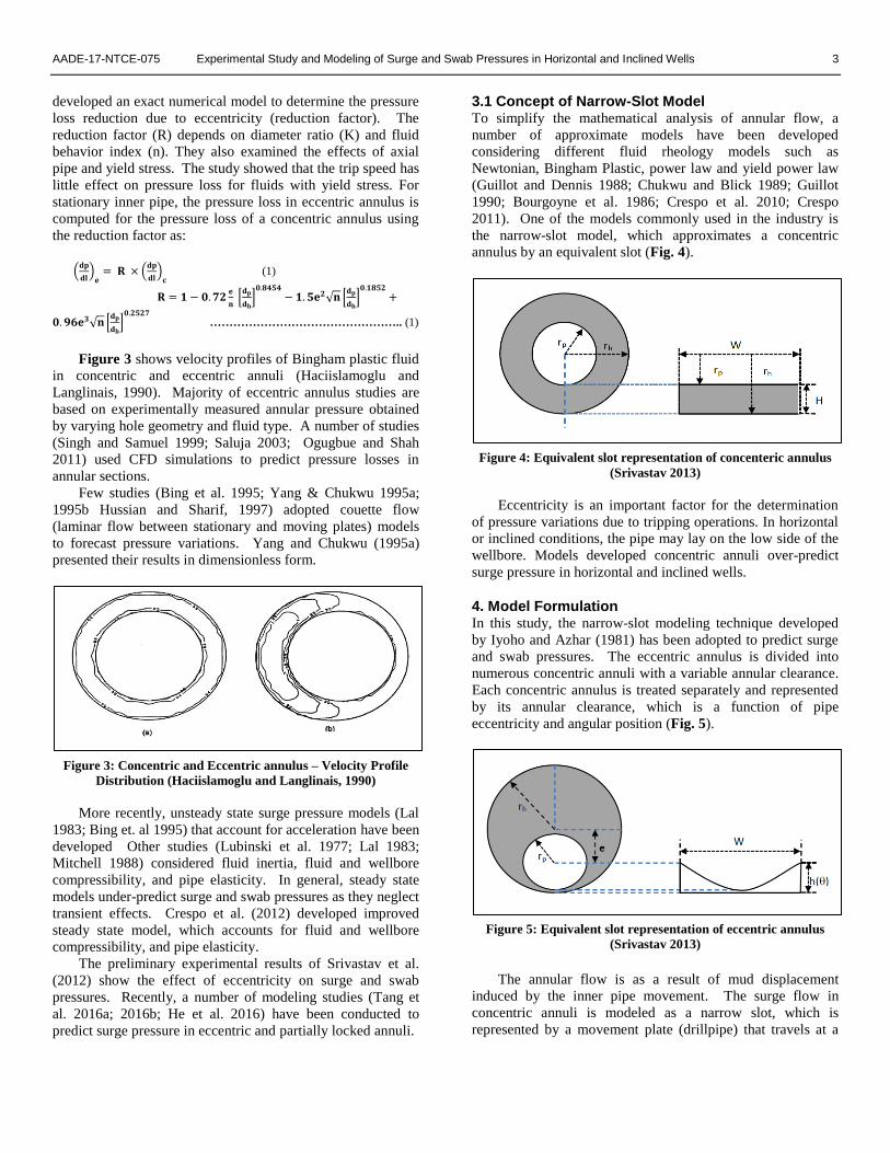
3.1 Concept of Narrow-Slot Model To simplify the mathematical analysis of annular flow, a
number of approximate models have been developed
considering different fluid rheology models such as
Newtonian, Bingham Plastic, power law and yield power law
(Guillot and Dennis 1988; Chukwu and Blick 1989; Guillot
1990; Bourgoyne et al. 1986; Crespo et al. 2010; Crespo
2011). One of the models commonly used in the industry is
the narrow-slot model, which approximates a concentric
annulus by an equivalent slot (Fig. 4).
Figure 4: Equivalent slot representation of concenteric annulus
(Srivastav 2013)
Eccentricity is an important factor for the determination
of pressure variations due to tripping operations. In horizontal
or inclined conditions, the pipe may lay on the low side of the
wellbore. Models developed concentric annuli over-predict
surge pressure in horizontal and inclined wells.
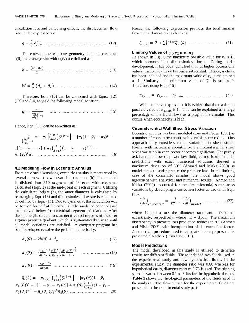
4. Model Formulation In this study, the narrow-slot modeling technique developed
by Iyoho and Azhar (1981) has been adopted to predict surge
and swab pressures. The eccentric annulus is divided into
numerous concentric annuli with a variable annular clearance.
Each concentric annulus is treated separately and represented
by its annular clearance, which is a function of pipe
eccentricity and angular position (Fig. 5).
Figure 5: Equivalent slot representation of eccentric annulus
(Srivastav 2013)
The annular flow is as a result of mud displacement
induced by the inner pipe movement. The surge flow in
concentric annuli is modeled as a narrow slot, which is
represented by a movement plate (drillpipe) that travels at a

4 R. Srivastav, R. Ahmed and A. Saasen AADE-17-NTCE-075
constant velocity Vp and stationary plate (hole or casing). The
following assumptions were presumed during the model
formulation:
The fluid is incompressible (constant density);
Steady state and isothermal Couette flow conditions;
Laminar flow;
Drillpipe moving at a constant speed, Vp;
Negligible wall slippage effects.
Figure 6 illustrates the representation of an eccentric
annulus by variable slot geometry. Flow in each discretized
section is solved as a narrow slot with a constant slot height of
h, which is a function of angular position () and eccentricity.
The expression for the slot height (Iyoho and Azar 1981) is
given as:
𝒉() = (𝒓𝒐𝟐 − 𝜺𝟐𝒄𝟐𝒔𝒊𝒏𝟐𝜽)𝟎.𝟓 − 𝒓𝒊 + 𝜺𝒄𝒄𝒐𝒔𝜽 ..…… (2)
where, is fractional eccentricity, which is calculated as:
𝜺 = 𝒆/𝒄, where c is the radial difference and e is offset distance
between pipe and borehole centers.
Figure 6: Discretized variable narrow slot into approximated
concentric annuli (Srivastav 2013)
Crespo (2011) developed model flow equations to
represent velocity profiles for (Fig. 7) YPL fluid in concentric
annulus with inner pipe axial motion. The velocity
distribution has three distinct flow regions:
Region I, the outer sheared region (0 ≤ y ≤ y1);
Region II, the plug zone region (y1 ≤ y ≤ y2);
Region III, the inner sheared region (y2 ≤ y ≤ h)
Figure 7: Yield power law velocity profile distribution through a
narrow slot (Crespo 2011)
Dimensionless surge pressure (1) and dimensionless
exponent (b) used in model development are expressed as:
𝝅𝟏 = (𝒏
𝒏+𝟏) (
𝒉
𝑽𝒑) (
∆𝑷
∆𝑳
𝒉
𝒌)
𝟏
𝒏 ………………...……….. (3)
𝒃 = 𝒏+𝟏
𝒏 ……………….…………………………….. (4)
The dimensionless plug thickness (π2) is determined from
the dimensionless plug-boundary limits (y̅1 and y̅2) as:
𝝅𝟐 = �̅�𝟐 − �̅�𝟏 ……………………...……………….. (5)
The dimensionless plug-boundary limits are obtained
from plug-boundary limits as:
�̅�𝟏 =𝒚𝟏
𝒉 𝒂𝒏𝒅 �̅�𝟐 =
𝒚𝟐
𝒉 …………………………….. (6)
Applying momentum balance (Crespo 2011), and
relationship can be established between dimensionless plug
thickness and surge pressure gradient as:
𝝅𝟐 = 𝟐𝝉𝒐 𝒉⁄
∆𝑷 ∆𝑳⁄ ………………….……………………….. (7)
From Fig. 7, if the velocity gradient in Region I is
negative, then it will be positive in Region III. The velocity at
y̅1 and y̅2 must be equal, as the velocity in the plugged zone is
uniform; therefore, V̅1 and V̅2 must be same at these localized
points. Thus:
(𝟏 − �̅�𝟏 − 𝝅𝟐 )𝒃 − (�̅�𝟏)𝒃 − 𝟏
𝝅𝟏= 𝟎 ……………. (8)
4.1 Flowrate Analysis The total dimensionless flow rate is the sum of individual flow
rates for each region. Therefore:
q̅t = ∫ (V̅1dy̅ + V̅2dy̅ + V̅3dy̅ )1
0dx …..…..…..….. (9)
where, q̅t is dimensionless total flow rate and is expressed as
q̅t = − q
WHVp …………..……………...…………….. (10)
Inserting the values of dimensionless velocities into Eq.
(9) and integrating, the following dimensionless expression
can be established for computing flow rate (Crespo 2011):
�̅�𝑡 = −𝜋1 [(𝑏
𝑏+1) �̅�1
𝑏+1 ] − [𝜋1(1 − �̅�1 − 𝜋2)𝑏 − 1][1 −
�̅�1 − 𝜋2] + 𝜋1 (1
𝑏+1) (1 − �̅�1 − 𝜋2)𝑏+1 −
𝜋1 (�̅�1)𝑏𝜋2 ………………………..………….......….. (11)
For a close-ended pipe, the annular flow rate is amount of
fluid being displaced during tripping operations. Neglecting
AADE-17-NTCE-075 Experimental Study and Modeling of Surge and Swab Pressures in Horizontal and Inclined Wells 5
circulation loss and ballooning effects, the displacement flow
rate can be expressed as:
𝑞 = 𝜋
4 𝑑𝑝
2𝑉𝑝 …….……………….....…………….. (12)
To represent the wellbore geometry, annular clearance
h() and average slot width (W) are defined as:
ℎ = (𝑑ℎ− 𝑑𝑝 )
2 ………………………....…………….. (13)
𝑊 = 𝜋
2 (𝑑𝑝 + 𝑑ℎ) ………………..……………….. (14)
Therefore, Eqn. (10) can be combined with Eqns. (12),
(13) and (14) to yield the following model equation.
�̅�𝑡 = − 1
(𝑑ℎ𝑑𝑝
)2
−1
………......……………………….. (15)
Hence, Eqn. (11) can be re-written as:
− 1
(𝑑ℎ𝑑𝑝
)2
−1
= −𝜋1 [(𝑏
𝑏+1) �̅�1
𝑏+1 ] − [𝜋1(1 − �̅�1 − 𝜋2)𝑏 −
1][1 − �̅�1 − 𝜋2] + 𝜋1 (1
𝑏+1) (1 − �̅�1 − 𝜋2)𝑏+1 −
𝜋1 (�̅�1)𝑏𝜋2 ………………………….……………….. (16)
4.2 Modeling Flow in Eccentric Annulus From previous discussions, eccentric annulus is represented by
several narrow slots with variable clearance (h). The annulus
is divided into 360 segments of 1 each with clearance
calculated (Eqn. 2) at the mid-point of each segment. Utilizing
the calculated height (h), the outer diameter is calculated by
rearranging Eqn. (13) and dimensionless flowrate is calculated
as defined by Eqn. (11). Due to symmetry, the calculation was
performed for half of the annulus. The modified equations are
summarized below for individual segment calculations. After
the slot height calculation, an iterative technique is utilized for
a given pressure gradient, which is systematically varied until
all model equations are satisfied. A computer program has
been developed to solve the problem numerically.
𝑑ℎ(𝜃) = 2ℎ(𝜃) + 𝑑𝑝 ……………..…………….. (17)
𝜋1(𝜃) = (𝑛
𝑛+1) (
ℎ(𝜃)
𝑉𝑝) (
∆𝑃
∆𝐿 ℎ(𝜃)
𝑘)
1
𝑛 ………....…….. (18)
𝜋2(𝜃) = 2𝜏𝑜 ℎ(𝜃)⁄
∆𝑃 ∆𝐿⁄ …………….………………….. (19)
�̅�𝑡(𝜃) = −𝜋1 (𝜃) [(𝑏
𝑏+1) �̅�1
𝑏+1 ] − [𝜋1 (𝜃)(1 − �̅�1 −
𝜋2 (𝜃))𝑏 − 1][1 − �̅�1 − 𝜋2(𝜃)] + 𝜋1(𝜃) (1
𝑏+1) (1 − �̅�1 −
𝜋2(𝜃))𝑏+1 − 𝜋1(𝜃) (�̅�1)𝑏𝜋2(𝜃) ……………………….. (20)
Hence, the following expression provides the total annular
flowrate in dimensionless form as:
�̅�𝑡𝑜𝑡𝑎𝑙 = 2 × ∑ �̅�𝑡𝜃=1801 (𝜃) …………..……….. (21)
Limiting Values of �̅�𝟏, �̅�𝟐 𝒂𝒏𝒅 𝝅𝟐 As shown in Fig. 7, the maximum possible value for y2 is H,
which becomes 1 in dimensionless form. During model
development, it has been identified that, at higher eccentricity
values, inaccuracy in y̅2 becomes substantial. Hence, a check
has been included and the maximum value of y̅2 is maintained
at 1. Similarly, the minimum value of y̅1 is set to 0.
Therefore, using Eqn. (16):
𝜋2,𝑚𝑎𝑥 = �̅�2,𝑚𝑎𝑥 − �̅�1,𝑚𝑖𝑛 …………..………….. (22)
With the above expression, it is evident that the maximum
possible value of π2,max is 1. This can be explained as a large
percentage of the fluid flows as a plug in the annulus. This
occurs when eccentricity is high.
Circumferential Wall Shear Stress Variation Eccentric annulus has been modeled (Luo and Peden 1990) as
a number of concentric annuli with variable outer radius. This
approach only considers radial variations in shear stress.
Hence, with increasing eccentricity, the circumferential shear
stress variation in each sector becomes significant. For purely
axial annular flow of power law fluid, comparison of model
predictions with exact numerical solutions showed a
maximum deviation of 30% (Ahmed and Miska 2009) as
model tends to under-predict the pressure loss. In the limiting
case of the concentric annulus, the model shows good
agreement with analytical and numerical results. Ahmed and
Miska (2009) accounted for the circumferential shear stress
variations by developing a correction factor as shown in Eqn.
(23).
(𝑑𝑝
𝑑𝑙)
𝑐𝑜𝑟𝑟𝑒𝑐𝑡𝑒𝑑=
1
𝐾0.27𝜀 (𝑑𝑝
𝑑𝑙)
𝑚𝑜𝑑𝑒𝑙 …………… (23)
where K and are the diameter ratio and fractional
eccentricity, respectively, where K = dp/dh. The maximum
discrepancy in pressure loss prediction reduces to 8% (Ahmed
and Miska 2009) with incorporation of the correction factor.
A numerical procedure used to calculate the surge pressure is
presented elsewhere (Srivastav 2013).
Model Predictions The model developed in this study is utilized to generate
results for different fluids. These included two fluids used in
the experimental study and few hypothetical fluids. In the
experimental study, the diameter ratio was 0.66 whereas for
hypothetical cases, diameter ratio of 0.73 is used. The tripping
speed is varied between 0.1 to 3 ft/s for the hypothetical cases.
Table 1 shows the rheological parameters of the fluids used in
the analysis. The flow curves for the experimental fluids are
presented in the experimental study part.

6 R. Srivastav, R. Ahmed and A. Saasen AADE-17-NTCE-075
Table 1: Rheology fluids considered in the analysis
Figures 8-13 show model predictions for fluids presented
in Table 1. For Newtonian fluid, expected surge pressure
trend with trip speed is observed (Fig. 8). This is consistent
with flow in circular pipes, in which the pressure loss is a
linear function of mean velocity under laminar flow condition.
Results of Bingham plastic fluid (Fig. 9) also demonstrate the
expected straight line trend with positive intercept indicating
yielding behavior of the fluid. Thus, before the fluid begins to
flow, the surge pressure gradient needs to overcome the yield
stress (o) value which is represented by the intercept.
Figures 10 and 11 present surge pressure predictions for
Power law fluids (F3 and 1% PAC –Polyanionic Cellulose).
The fluid flow characteristics are defined by fluid consistency
index (k) and fluid behavior index (n). The surge pressure
curves are strongly affected by fluid parameter, n, which
determines non-linearity of the curves. Due to their shear
thinning behavior, surge pressure is not very sensitive to the
change in trip speed as it is observed with Newtonian fluid.
From the figures, it is also evident that with increasing
eccentricity surge pressure decreases considerably. Both fluid
parameters (k and n) contribute to downhole pressure
variations. The diameter ratio (K) is another factor that
influences surge pressure and will be discussed later.
Figure 8: Fluid F1 model predictions
Figure 9: Fluid F2 model predictions
Figure 10: Fluid F3 model predictions
Figure 11: Fluid 1% PAC model predictions
Like Bingham plastic fluids, Yield power law fluids (F4
and 1% Xanthan gum) need minimum pressure gradient to
overcome the yield stress and initiate the flow (Figs. 12 and
13). At higher pipe velocities, the effect of trip speed
diminishes due to significant shear thinning. Surge pressure
depicted reducing trend with increasing eccentricity. As
shown in Fig. 12, to generate the same level of surge pressure
the trip speed has to be tripled in 60% eccentric annulus.
Fluid Type Test
Fluid o (lbf/100ft2) k (lbf.s
n/100ft2) n
Newtonian F1 0.00 0.8 1.00
Bingham
Plastic F2 6.64 0.8 1.00
Power Law F3 0.00 0.8 0.50
Power Law 1% PAC 0.00 2.77 0.63
Yield Power
Law F4 6.64 0.8 0.50
Yield Power
Law
1%
Xanthan Gum
20.90 6.41 0.33

AADE-17-NTCE-075 Experimental Study and Modeling of Surge and Swab Pressures in Horizontal and Inclined Wells 7
Figure 12: Fluid F4 model predictions
Figure 13: Fluid 1% Xanthan Gum model predictions
5. Experimental Study The main objective of this study is to examine the effects of
different drilling parameters such as trip speed, fluid rheology
and eccentricity on surge and swab pressures.
5.1 Experimental Setup The existing small-scale setup (Crespo 2011) has been
improved to satisfy experimental requirements. The tests were
performed at ambient conditions in a vertical annulus with
proper control of inner pipe axial speed and eccentricity. The
setup (Fig. 14) has the capability to accurately control trip
speed and record measurements. A detailed schematic of the
set-up is presented in Fig. 15. The set-up includes the
following components:
A 2-inch polycarbonate tube (Casing);
1.32-inch inner steel pipe (L = 90 inches);
Hoisting system: a gearmotor with pulley and cable
system to raise and lower the inner pipe at a
controlled speed;
Differential pressure sensor;
Data acquisition and control system (personal
computer and data collection card); and
Fluid preparation mixing and collection tanks.
Figure 14: Experimental setup (Srivastav 2013)
Figure 15: Schematic of experimental setup (Srivastav 2013)
A 148-inch long polycarbonate tube is used as the
casing/borehole and attached to the supporting structural
frame as show in Fig. 14. The bottom of the tube has a drain
valve. The tube is supported by a blind flange at the bottom.

8 R. Srivastav, R. Ahmed and A. Saasen AADE-17-NTCE-075
The inner pipe eccentricity was maintained using three screws
(Fig. 16a), which are placed at the bottom of the inner pipe
maintaining 120 apart. The screws were tested for smooth
tripping operation. During the experiment, the pipe
eccentricity was maintained at about 90% to have a small
clearance between the screws that maintain the pipe
eccentricity and the casing wall. The clearance reduced the
friction and maintained smooth pipe movement during the test.
Figure 16:(a) Screws used to maintain ecentricity; (b) Variable
speed motor with pulley and cable system (Srivastav 2013)
The hoisting system comprised of a variable speed motor
(Fig. 16b) to lift the inner pipe at the desired speed. The
maximum trip speed was 1 ft/s with speed controlling
accuracy of ±0.01 ft/s. However, the maximum speed limit of
the experiments were slightly lower (0.8 ft/s) than 1 ft/s
because higher speed require longer stroke length to establish
a steady state flow condition. The setup has an effective
stroke length of 67 inches and pipe movement is achieved
with winding and unwinding of the wire on the pulley as the
motor rotated in clockwise and anticlockwise directions.
A differential pressure sensor was connected to the test
section to measure surge pressure. It was tested and calibrated
prior to performing the experiments. The pressure port
tapping distance was 1 ft and the pressure measuring span was
0.0-1.0 psi with an accuracy of ±0.005 psi.
The desired polymeric fluids were prepared in an 8-gallon
mixing tank using a variable speed Stirrer (Silverson L4RT).
The stirrer was capable of both varying the speed as well as
vertical movement that provided more efficient means for
mixing and preparing the test fluids. Once the fluids were
prepared, they were transferred to the test annular section and
experiments were performed. The test started with the inner
pipe at the top to attain a full stroke using a hoisting system.
The data acquisition system and the pressure transducer were
used to record surge pressure data for different tripping
speeds. A detailed test procedure is presented elsewhere
(Srivastav 2013).
5.2 Test Materials Experiments were performed varying concentrations of
polymeric fluids (Polyanionic Cellulose and Xanthan Gum
suspensions). Flow behavior of Polyanionic Cellulose
suspensions (PAC) best fits the power law model whereas that
of Xanthan gum suspensions best fits the yield power law
model. The tests were performed in concentric and eccentric
annuli. Two rotational viscometers (spring factor of 1 and 1/5
respectively) were used to measure rheology of the fluids.
Using the polymers, test fluids with different polymer
concentrations were prepared and their rheological properties
were measured (Figs. 17 and 18). Script A is used to identify
fluids utilized in concentric annulus test and Script B used to
identify fluids utilized in eccentric annulus test. Rheologies of
fluids used in concentric annulus test are similar to the
rheologies of fluids used in the eccentric annulus test.
Figure 17: Rheology measurements for PAC based fluids used in
eccentric annulus test (Srivastav 2013)
Figure 18: Rheology measurements for Xanthan gum based fluids used in
eccentric annulus test (Srivastav 2013)
5.3 Experimental Results and Model Predictions For PAC based fluids (power law fluids), model predictions
show reasonable agreement with experimental measurements
(Figs. 19 and 20). The maximum discrepancy between
measurements and predictions is 13%, which can be attributed
to pipe oscillation at higher tripping speeds and model
inaccuracy because of neglecting the circumferential shear
stress variations. Although correction factors are introduced
in model formulation to account for circumferential shear
stress variations, there are still discrepancies due to velocity
profile differences. This discrepancy can also be a result of
other modeling assumptions.

AADE-17-NTCE-075 Experimental Study and Modeling of Surge and Swab Pressures in Horizontal and Inclined Wells 9
Figure 19: Surge gradient vs. pipe speed for = 0.9; PAC 1% (Srivastav 2013)
Figure 20: Surge gradient vs. pipe speed for = 0.9; PAC 0.5%
(Srivastav 2013)
Figures 21 and 22 compare experimental results with
model predictions for Xanthan gum (XG) based fluids, which
best fits the YPL rheology model. Model predictions were
comparable to experimental results with a maximum
discrepancy of 14% at high tripping speeds. The deviation can
be attributed to the model weaknesses discussed earlier. It is
evident that with decreased viscous propety, there is a gradual
reduction in the generated surge pressure.
Figure 21: Surge gradient vs. pipe speed; = 0.9; XG 1%
(Srivastav 2013)
Figure 22: Surge gradient vs. pipe speed; = 0.9; XG 0.5%
(Srivastav 2013)
5.4 Parametric Study The parametric study is performed between two hypothetical
fluids, one being power law fluid while other being yield-
power law fluid. The only rheological difference between the
two fluids is yield stress of the YPL fluid. The effects of
diameter ratios for both concentric and eccentric annulus are
studied. The casing diameter is kept constant while the inner
pipe diameter is varied. The fluid parameters and diameter
ratios used during the study are shown in Table 2.
Table 2: Fluid type and diameter ratios used for parametric study
Figures 23-26 shows surge pressure predictions as a
function of pipe velocity for both concentric and eccentric
annulus. It is evident from the figures that, as the surge
pressure increases with diameter ratio due to decreased
annular clearance. Moreover, surge pressure occurring in
concentric annulus significantly higher than the one occurring
in eccentric annulus with similar geometry. It can be inferred
from the results that, for low diameter ratios, the major
contributing factors affecting the surge pressure are the fluid
rheological parameters, trip speed and eccentricity. As seen
from Figs. 23 and 24, the YPL fluid tends to generate higher
pressure surges when compared to a similar flow of power law
fluid.

10 R. Srivastav, R. Ahmed and A. Saasen AADE-17-NTCE-075
Figure 23: Effect of diameter ratios on surge pressure, Fluid F5 (Srivastav 2013)
Figure 24: Effect of diameter ratios on surge pressure, Fluid F6 (Srivastav 2013)
Figure 25: Effect of diameter ratios on surge pressure, Fluid F5 (Srivastav 2013)
Figure 26: Effect of diameter ratios on surge pressure, Fluid F6 (Srivastav 2013)
5.5 Comparing Concentric and Eccentric Annulus The experimental measurements and model predictions are
presented together to show the reduction in surge pressure due
to eccentricity. The maximum surge pressure reduction of
32% (Fig. 27) was observed with power law fluid (PAC
0.75%) while reduction of 38% (Fig. 28) was occurred with
YPL fluid (1% Xanthan gum). The model predictions here
provide a useful insight to the effects of eccentricity on surge
pressure. The experimental data show smaller reduction in
surge pressure than the model predictions. This could be
attributed to the pipe lateral movement during the test, which
slightly changes the eccentricity of the pipe causing surge
pressure reduction in concentric pipe as the pipe tends to move
toward the wall and increase in surge pressure as highly
eccentric pipe moves toward the center. During the
experiment, it was difficult to maintain both fully concentric
and fully eccentric pipe configurations. Hence, model
predictions for concentric and eccentric annuli can be
considered as the limiting boundary for surge pressure of a
given fluid and diameter ratio (K), since experimental results
were always within the model prediction of concentric and
eccentric annulus.
Figure 27: Measured and predicted surge pressures for 1% XG
fluid (Srivastav 2013)

AADE-17-NTCE-075 Experimental Study and Modeling of Surge and Swab Pressures in Horizontal and Inclined Wells 11
Figure 28: Measured and predicted surge pressures for 0.75%
PAC (Srivastav 2013)
Conclusions The numerical model developed in this study precisely
predicts surge and swab pressures simulating downhole
pressure fluctuations occurring during tripping in inclined and
horizontal wells. The model utilizes the existing variable
narrow-slot approximation technique to account for pipe
eccentric in surge pressure calculation. Based on the outcomes
of this investigation, the following conclusions can be made:
The present model predicts surge and swab pressures
of yield power law fluid in eccentric annulus (i.e.
eccentricity ranging from 0 to 90%) with reasonable
accuracy (maximum discrepancy of 14%).
Eccentricity has considerable effects on surge and
swab pressures. Both experimental and theoretical
results show surge pressure reduction of up to 40% as
a result of eccentricity.
Results show that for highly shear thinning fluids, a
small decrease in surge pressure can considerably
increase the safe tripping speed limit.
Surge pressure predictions for concentric and
eccentric model can be considered as the boundary
limits for the expected surge pressures. In real field
condition, due to pipe lateral movement the pipe does
not maintain the concentric or fully eccentric
geometry throughout, resulting in surge pressure
variations between these to limits.
In general, fluid rheological parameters, tripping
speeds and diameter ratios considerably affect the
generated pressure surges.
Acknowledgments The authors wish to express their gratitude to the University of
Oklahoma, Superior Completion Services, Mr. Joe Flenniken
and Well Construction Technology Center for their kind
support.
Nomenclature q̅t = Total dimensionless flow rate
q̅t() = Total dimensionless flow rate for the segment
�̅� = Surge/Swab pressure
�̅�𝑡𝑜𝑡𝑎𝑙 = Total dimensionless flow rate for all the
segments
�̅�1 = Dimensionless lower boundary limit of Region II
�̅�2= Dimensionless upper boundary limit of Region II
dh = Hole/Casing diameter
dp = Pipe diameter
Vms = Effective mud velocity
Vp = Pipe velocity
Vv = Velocity due to pipe movement
y1 = Lower limit of Region II
y2 = Upper limit of Region II
𝐾 = Clinging Constant
𝑃𝑠 = Surge/Swab pressure
�̅� = Dimensionless flow rate
𝑉𝑎𝑒 = Effective annular mud velocity
Aa = Annular area
Ap = Area displaced by drill pipe
b = Constant
c = radial clearance (ro – ri)
dh() = Hole / Casing diameter of the segment for variable
slot calculations
e = inner pipe offset from the center
f = friction factor
fb = Bingham fluid modified friction factor
fl = laminar flow regime friction factor
ft = turbulent flow regime friction factor
h = Slot Thickness
h() = Segment Slot Thickness
k = Consistency Index
L = Length of the wellbore
n = Fluid behavior index
N = Spring factor
q = Actual flow rate
Qi = drill-pipe flow rate
R = Reduction factor
Re = Reynolds number
ri = Outer radius of inner pipe
ro = Inner radius of outer pipe
S = Bingham number / Plasticity
v = Voltage
W = Slot width
𝐾 = Diameter ratio (K= 𝑑𝑝 𝑑ℎ⁄ )
Greek Letters
= Fractional eccentricity
= Conductance number
µp = Plastic viscosity
𝛾𝑤 = Wall shear rate
ρ = Fluid density
π = Pi
π1 = Dimensionless pressure
π1() = Dimensionless pressure for the segment

12 R. Srivastav, R. Ahmed and A. Saasen AADE-17-NTCE-075
π2 = Dimensionless plug thickness
π2() = Dimensionless plug thickness for the segment
= Correction factor
θi = Dial reading
τ = Shear stress
τw = Shear stress at the wall
τ0 = Yield stress dv
dy = Shear rate
dp
dl = Pressure gradient
∆L = Slot length/Wellbore depth
∆P = Pressure drop
Subscripts h = Hole
p = Pipe
= Angle / segment for eccentric annulus discretization
e = eccentric annulus
c = concentric annulus
References Ahmed, R. and Miska, S. 2009. Advanced Drilling and Well
Technology, Chapter 4, Society of Petroleum Engineers, pp217.
Bing, Z., Kaiji, Z. and Qiji, Y. 1995. Equations Help Calculate Surge
and Swab Pressures in Inclined Well, Oil & Gas Journal, Vol.
93, pp 74-77, 18 September.
Bourgoyne, A. T. 1986. Applied Drilling Engineering, SPE Textbook
Series, Vol. 2, Richardson, Texas, pp. 167-171.
Burkhardt, J. A. 1961. Wellbore Pressure Surges Produced by Pipe
Movement, Journal of Petroleum Technology, June, pp 595-605.
Cannon, G. E. 1934. Changes in Hydrostatic Pressure due to
Withdrawing Drillpipe from the Hole, API Drilling and
Production Practices, pp 42-47.
Cardwell, W. T. 1953. Pressure Changes in Drilling Wells Caused by
Pipe Movement, API Drilling and Production Practices, pp 97-
112.
Chukwu, G. A. and Blick, E. F. 1989. Couette Flow of Non-
Newtonian Power-Law Fluids, Applied Simulation & Modeling,
Acta Press, Anaheim, California, 13-15 November.
Clark, E. H. 1956. A Graphic View of Pressure Surges and Lost
Circulation, API Drilling & Production Practices, pp 424-438.
Clark, R. K. and Fontenot, J. E. 1974. Field Measurements of the
Effects of Drillstring Velocity, Pump Speed and Lost
Circulation Material on Downhole Pressures, Paper SPE-4970,
presented at the 49th Annual Fall Meeting of the Society of
Petroleum Engineers of AIME, Houston, Texas ,6-9 October.
Crespo, F. 2011. Experimental Study and Modeling on Surge and
Swab Pressures for Yield-Power-Law drilling fluids, Master’s
Dissertation Thesis, Mewbourne School of Petroleum &
Geological Engineering, University of Oklahoma.
Crespo, F., Ahmed, R. and Saasen, A. 2010. Surge and Swab
Pressure Predictions for Yield-Power-Law Drilling Fluids, SPE
138938, SPE Latin American & Caribbean Petroleum
Engineering Conference, Lima, Peru, 1-3 December 2010.
Crespo, F., Ahmed, R., Enfis M., Saasen A. and Amani M. 2012.
Surge-and-Swab Pressure Predictions for Yield-Power-Law
Drilling Fluids, SPE Drilling & Completions, December.
Filip, P. and David, J. 2003. Axial Couette-Poiseuille flow of Power-
Law Viscoplastic Fluids in Concentric Annuli, Journal of
Petroleum Science and Engineering, Vol. 40, pp. 111 – 119.
Goins, W. C., Weichhert, J. P., Burba, J. L., Dawson, D. D. and
Teplitz, A. J. 1951. Down-the-Hole Pressure Surges and their
Effect on Loss of Circulation, API Drilling and Production
Practices, pp 125-132.
Guillot, D. 1990. Rheology of Well Cementing Slurries, in E.B.
Nelson, Ed., Well Cementing, Schlumberger, Houston, Texas,
pp 4:01–37.
Guillot, D. and Dennis, J. D. 1988. Prediction of Laminar and
Turbulent Friction Pressures of Cement Slurries in Pipes and
Centered Annuli, Paper SPE- 18377, presented at the European
Petroleum Conference, London, 18-19 October.
Haciislamoglu, M. and Langlinais, J. 1991. Effect of Pipe
Eccentricity on Surge Pressures, Journal of Energy Resources
Technology, September, Vol. 113 / 157.
Haige, W. and Xisheng, L. 1996. Study on Surge Pressure for Yield-
Pseudoplastic Fluid in a Concentric Annulus, Applied
Mathematics and Mechanics, Vol. 17, No. 1, pp 15-23 January.
He, S., Srivastav, R., Tang, M. and Ahmed, R. 2016. A New
Simplified Surge and Swab Pressure Model for Yield-Power-
Law Drilling Fluids, Journal of Natural Gas Science and
Engineering, Volume 28, January 2016, Pages 184–192.
Horn, A. J. 1950. Well Blowouts in California Drilling Operations,
Causes and Suggestions for Prevention, API Drilling and
Production Practices, pp 112-128.
Hussain, Q. E. and Sharif M. A. R. 2000. Numerical Modeling of
Helical Flow of viscoplastic Fluids in eccentric annuli, AIChE
Journal, October, Vol. 46, No. 10.
Iyoho A. W. and Azar J. J. 1981. An Accurate Slot-Flow Model for
Non-Newtonian Fluid Flow Through Eccentric Annuli, Society
of Petroleum Engineers of AIME, October.
Lal, M. 1983. Surge and Swab Modeling for Dynamic Pressures and
Safe Trip Velocities, Paper SPE-11412, presented at the
IADC/SPE Drilling Conference, New Orleans, Louisiana, 20-23
February.
Lin, S. H. and Hsu, C. C. 1980. Generalized Couette Flow of a Non-
Newtonian Fluid in Annuli, Industrial & Chemical Engineering
Fundamentals, Vol. 19, No. 4, pp 421-424.
Lubinski, A., Hsu, F. H. and Nolte, K. G. 1977. Transient Pressure
Surges Due to Pipe Movement in an Oil Well, Fevue de
l’Institut Francais du Petrole, May-June.
Luo, Y. and Peden, J.M. 1990. Flow of Non-Newtonian Fluids
through Eccentric annulus, SPE Production Engineering,
February.
Malik, R. and Shenoy, U. V. 1991. Generalized Annular Couette
Flow of a Power-Law Fluid, Industrial and Engineering
Chemical Research, Vol. 30, pp 1950-1954.
Mitchell, R. F. 1988. Dynamic Surge/Swab Pressure Predictions, SPE
Drilling Engineering Journal, September, pp 325-333.
Ogugbue, C. C. and Shah, S. N. 2011. Laminar and Turbulent
Friction Factors for Annular Flow of Drag-Reducing Polymer
Solutions in Coiled-Tubing Operations, SPE Drilling &
Completion, December, pp. 506-518
Ormsby, G. S. 1954. Calculation and Control of Mud Pressures in
Drilling and Completion Operations, API Drilling and
Production Practices, pp 44-55.
Ramsey, M.S., Miller, J.F., Morrison, M.E. and Robinson, L.H. 1983.
Bit Hydraulics: Net Pressure Drops Are Lower Than You Think,
World Oil, October, pp 65-67.
Saluja, G. 2003. Investigation of CFD Based Simulation for Non-
Newtonian Fluid Flow in Concentric and Eccentric Annuli,
Master’s Dissertation Thesis, Mewbourne School of Petroleum
& Geological engineering, University of Oklahoma.
Schuh, F. J. 1964. Computer Makes Surge-Pressure Calculations
Useful, Oil & Gas Journal, Vol. 62, No. 31, pp 96-104.

AADE-17-NTCE-075 Experimental Study and Modeling of Surge and Swab Pressures in Horizontal and Inclined Wells 13
Singh, A. P. and Samuel, R. 2009. Effect of Eccentricity and Rotation
on Annular Frictional Pressure Losses with Standoff Devices,
SPE-124190, SPE Annual Technical Conference & Exhibition,
New Orleans, Louisiana, 4-7 October.
Srivastav, R., Crespo, F., Enfis, M., Ahmed, R., Saasen, A. and
Laget, M. 2012. Surge and Swab Pressures in Horizontal and
Inclined Wells, SPE-152662, SPE Latin American & Caribbean
Petroleum Engineering Conference, Mexico City, Mexico, 16-
18 April.
Srivastav, R. 2013. Experimental Study and Modeling on Surge and
Swab Pressures in Eccentric Annulus, Master’s Dissertation
Thesis, Mewbourne School of Petroleum & Geological
Engineering, University of Oklahoma.
Tang, M., Ahmed, R. and He, S. 2016a. Simplified Surge Pressure
Model for Yield Power Law Fluid in Eccentric Annuli, Journal
of Petroleum Science and Engineering, Volume 145, September,
346–356.
Tang, M., Ahmed, R. and He, S. 2016b. Modeling of yield-power-
law fluid flow in a partially blocked concentric annulus, Journal
of Natural Gas Science and Engineering, Volume 35, Part A,
555–566.
Vaughn, Robert D. 1965, Axial Laminar Flow of Non-Newtonian
Fluids in Narrow Eccentric Annuli, SPE 1138, Society of
Petroleum Engineers.
Wagner, R. R., Halal, A. S. and Goodman, M. A. 1993. Surge Field
Tests Highlight Dynamic Fluid Response, Paper SPE-25771,
presented at the IADC/SPE Drilling Conference, Amsterdam
(23-25 February).
Walton I.C. and Bittleston S. H. 1991. The axial flow of a Bingham
plastic in a narrow eccentric annulus, J. Fluid Mech., Vol 222,
pp. 39-60.
White, Z., Zamora, M., and Svodoba, C. 1997. Downhole
Measurements of Synthetic-Based Drilling Fluid in an Offshore
Well Quantify Dynamic Pressure and Temperature
Distributions, SPE Drilling and Completion, pp 149-157
(September).
Yang, L. and Chukwu, G. A. 1995a. Couette Flow of Non-
Newtonian Power-Law Fluids in Narrow eccentric Annuli, Ind.
Eng. Chem. Res., 34, pp. 936-942.
Yang, L. and Chukwu, G. A. 1995b. A Simplified Couette Flow
solution of Non-Newtonian Power-Law Fluids in eccentric
annuli, The Canadian Journal of chemical engineering, Volume
73, (April).