AA21-400 Cabin PA System - Dallas Avionics · 1.1 Introduction This manual contains information on...
29
SPECIAL NOTICE This product is now licensed to Anodyne Electronics Manufacturing (AEM) from Northern Airborne Technology (NAT)/Cobham Aerospace Communications (CAC). AEM is responsible for all matters related to this product, including sales, support and repair services. Please note the transition to convert product manuals and supporting documentation is an ongoing process and is being addressed on an ‘as needed’ basis. All references to NAT product part numbers (and associated images) are equivalent to AEM product part numbers. Contact info: Anodyne Electronics Manufacturing Corp. #15-1925 Kirschner Road Kelowna B.C. Canada V1Y 4N7 Email: [email protected] Toll Free: 1-888-763-1088 Phone: 1-250-763-1088 Fax: 1-250-763-1089 www.aem-corp.com
Transcript of AA21-400 Cabin PA System - Dallas Avionics · 1.1 Introduction This manual contains information on...

SPECIAL NOTICE
This product is now licensed to Anodyne Electronics Manufacturing (AEM) from Northern Airborne Technology (NAT)/Cobham Aerospace Communications (CAC). AEM is responsible for all matters related to this product, including sales, support and repair services. Please note the transition to convert product manuals and supporting documentation is an ongoing process and is being addressed on an ‘as needed’ basis. All references to NAT product part numbers (and associated images) are equivalent to AEM product part numbers.
Contact info: Anodyne Electronics Manufacturing Corp. #15-1925 Kirschner Road Kelowna B.C. Canada V1Y 4N7 Email: [email protected] Toll Free: 1-888-763-1088 Phone: 1-250-763-1088 Fax: 1-250-763-1089 www.aem-corp.com

CONFIDENTIAL AND PROPRIETARY TO ANODYNE ELECTRONICS MANUFACTURING CORP.
INSTALLATION AND OPERATION MANUAL
REV 5.00 November 9, 2016
Anodyne Electronics Manufacturing Corp. 15-1925 Kirschner Road Kelowna, BC, Canada.
V1Y 4N7
Telephone (250) 763-1088 Facsimile (250) 763-1089
Website: www.aem-corp.com
© 2016 Anodyne Electronics Manufacturing Corp. (AEM), All Rights Reserved
SM34 AA21-400 Cabin PA System

AA21-400 Cabin PA System
SM34 Installation and Operation Manual
Installation and Operation Manual Page ii ENG-FORM: 820-0100.DOTX
CONFIDENTIAL AND PROPRIETARY TO ANODYNE ELECTRONICS MANUFACTURING CORP.
COPYRIGHT STATEMENT © 2016 Anodyne Electronics Manufacturing Corp. (AEM), All Rights Reserved This publication is the property of AEM and is protected by Canadian copyright laws. No part of this document may be reproduced or transmitted in any form or by any means including electronic, mechanical, photocopying, recording, or otherwise, without the prior written permission of AEM.

AA21-400 Cabin PA System
SM34 Installation and Operation Manual
Installation and Operation Manual Page iii ENG-FORM: 820-0100.DOTX
CONFIDENTIAL AND PROPRIETARY TO ANODYNE ELECTRONICS MANUFACTURING CORP.
Prepared By: Checked By: Approved By:
The status of this installation and operation manual is controlled by the revision shown on the title page. The status of each section is controlled by revision shown in the footer of each page. All revisions affecting sections of this manual have been incorporated.
AEM MANUAL REVISIONS
Section Revision Number Revision Description Date
All Rev: 5.00 ECO1054: AEM Rebranding Nov 9, 2016
Tony Pearson DesignerDec 6, 2016
Loen Clement DesignerDec 06, 2016
Tom Betzelt Product Support Manager Dec 7, 2016
Todd Blackstock R&D Manager Dec 9/16

AA21-400 Cabin PA System
SM34 Installation and Operation Manual
Installation and Operation Manual Page iv ENG-FORM: 820-0100.DOTX
CONFIDENTIAL AND PROPRIETARY TO ANODYNE ELECTRONICS MANUFACTURING CORP.
Table of Contents Section Title Page 1.0 Description 1.1 Introduction 1-1 1.2 Purpose of Equipment 1-1 1.3 Features 1-1 1.4 Specifications 1-2 1.4.1 Electrical Specifications 1-2 1.4.2 Physical Specifications 1-4 1.4.3 Environmental Specifications 1-4 1.5 Accessories Required But Not Supplied 1-5 2.0 Installation 2.1 Introduction 2-1 2.2 Unpacking and Inspection 2-1 2.3 Installation Procedures 2-1 2.3.1 Note to Installers 2-1 2.3.2 Warnings 2-1 2.3.3 Cautions 2-2 2.3.4 Cabling and Wiring 2-2 2.3.5 Post-Installation Checks 2-2 2.3.6 Adjustments and Connections 2-3 2.4 Continued Airworthiness 2-4 2.5 Installation Drawings 2-5 3.0 Operation 3.1 Introduction 3-1 3.2 Operation Specifics 3-1 3.3 Techniques of Voice Transmission 3-1 3.4 Basic Operation 3-1 3.4.1 Power Up 3-1 3.4.2 Input Function Selection 3-2 3.4.3 Volume Control 3-2 3.4.4 Mode Switches 3-3 3.4.5 Remote Power Switch 3-3

AA21-400 Cabin PA System
SM34 Installation and Operation Manual
Build Standard: 5.00 Nov 09, 2016 Page 1-1 ENG-FORM: 800-0100.DOTX
CONFIDENTIAL AND PROPRIETARY TO ANODYNE ELECTRONICS MANUFACTURING CORP.
Section 1.0 Description
1.1 Introduction
This manual contains information on the AA21-400 Cabin PA System. Information in this section consists of purpose of equipment, features and specifications.
1.2 Purpose of Equipment
The AA21-400 Cabin PA control unit is designed to provide centralized control for an aircraft’s internal and external PA systems. The design is contained in one panel-mounted unit, with an illuminated faceplate. All audio and keylines are interfaced to existing aircraft audio systems. Front panel switches provide selection of the various operational modes of the AA21 and a potentiometer provides output volume control.
1.3 Features
The AA21-400 provides selection and control of internal and/or external PA system(s) installed in an aircraft. The integrated 25 W speaker driver circuit is designed to drive one 8 speaker arrangement for internal paging. The AA21-400 also provides a low-level audio signal output that drives the input on a remote mounted power amplifier. The output is designed to drive the PA110/220 or PA250/700 series amplifiers. The AA21-400 provides generation of wail and yelp siren audio on the low level output when selected on the front panel. A ‘+3 dB’ function allows the output level of the system to be varied by 3 dB. When the input control line is grounded, the output is reduced by approximately 3 dB, and removing the ground returns the system to full output. Thermal protection is designed into the intermediate and final stage amplifiers to protect the unit during very hot or extended high power operating conditions. Four front panel switches provide selection of the various operational modes of the AA21-400 as described in Section 3 of this manual (Operation).

AA21-400 Cabin PA System
SM34 Installation and Operation Manual
Build Standard: 5.00 Nov 09, 2016 Page 1-2 ENG-FORM: 800-0100.DOTX
CONFIDENTIAL AND PROPRIETARY TO ANODYNE ELECTRONICS MANUFACTURING CORP.
1.4 Specifications
1.4.1 Electrical Specifications
Power Supply Linear DC (with reverse & over voltage protection): Normal: +27.5 Vdc nominal. +22.0 Vdc minimum. +30.3 Vdc maximum. +18.0 Vdc emergency. Input Current: 2.3 A max. full speaker power (35 W) @ +27.5 Vdc.
2.9 A max (35 W) with 0.40 A load on Switched Power Output. 0.40 A idle @ +27.5 Vdc. Backlighting: 150 mA max @ +27.5 Vdc. Input Signals Microphone: 150 Ohm amplified dynamic. 250 mVrms rated input level. ALC Automatic level controlled for maximum intelligibility without
distortion starts @ 130 mVrms. Impedance 130 Ohm 10%. Music: Only one of Radio (Receive) or CD may be enabled at a time.
Radio (Receive) 2.5 Vrms into 1k 10%.
CD 1.0 Vrms into 11k 10%. PA key: Active low. Max. current source 15 mA. +3dB key: Active open, isolated through optical relay. Max. current source 13
mA. Reduces all audio, except sidetone, by 3 dB when grounded. The output will be reduced 2 to 3 dB if operating above 25 W on speaker output, or above 6.5 Vrms on PA output.
Input to Input Crosstalk: -40 dB from rated output.

AA21-400 Cabin PA System
SM34 Installation and Operation Manual
Build Standard: 5.00 Nov 09, 2016 Page 1-3 ENG-FORM: 800-0100.DOTX
CONFIDENTIAL AND PROPRIETARY TO ANODYNE ELECTRONICS MANUFACTURING CORP.
Output Signals
Speaker: Impedance and short circuit protected.
10% THD 20 W single tone into 8 @ 50% duty cycle. Continuous. 20 W voice/music into 8 @ 100% duty cycle. Continuous.
Note: Distortion is 3% THD at 10% of continuous output power
rating.
> 10% THD 35 W max. into 8 with 2.5 Vrms into Radio (Receive) input. Non-continuous (short term).
Audio bandwidth: Mic input: 3 dB roll-off from 350 Hz to 3 kHz Radio (Receive)/CD input: 3 dB roll-off from 350 Hz to 6 kHz
PA: Selectable by internal jumper for either PA110/220 (6.5 Vrms 10% into 600 ) or PA250/700 (0.5 Vrms 10% into 600 ) for rated output. Distortion: 3% THD at rated output.
Audio bandwidth: Mic input: 3 dB roll-off from 350 Hz to 3 kHz Radio (Receive)/CD input: 3 dB roll-off from 350 Hz to 6 kHz
Siren: Only available on PA output (735 to 1620 Hz). Yelp and wail
modes with adjustable rates. Siren level control provided for yelp/wail by one internal trimpot.
Sidetone: Adjustable 0-100 mW into 600 with 10% THD Audio bandwidth: 3 dB roll-off from 350 Hz to 3 kHz Input to Output -50 dB from rated output. Crosstalk: Audio Noise Level: -50 dB from rated output. (without signal) Switched Power: +27.5 Vdc @ 0.40 Amps max. Over current protected.
Temperature Sensor The unit contains a temperature sensor IC which when triggered
reduces the input signals by 3 dB. The IC threshold is set to approximately 130 C. Annunciator Power On (illuminates green when active)

AA21-400 Cabin PA System
SM34 Installation and Operation Manual
Build Standard: 5.00 Nov 09, 2016 Page 1-4 ENG-FORM: 800-0100.DOTX
CONFIDENTIAL AND PROPRIETARY TO ANODYNE ELECTRONICS MANUFACTURING CORP.
1.4.2 Physical Specifications
Height 1.11 0.03” (28.1 0.8 mm) Depth 6.53 0.03” (165.9 0.8 mm) behind panel (including connector). Width 4.96 0.03” (126.0 0.8 mm) behind panel. 5.75 0.03” (146.1 0.8 mm) in front of panel. Weight 1.40 0.07 lbs. (0.64 0.03 kg) Mounting Std. Dzus Mounting (4 fasteners) Faceplate Engraved acrylic edge lit panel, with 28 Vdc backlighting. Material/Finish Chassis & cover: 5052-H32 brushed aluminum with chromate
conversion finish. Heat sinks: de-burred 6063-T6 aluminum with chromate conversion finish. Connector Male filtered 25 pin D-subminiature with Positronics V5 locking
tabs.
1.4.3 Environmental Specifications
Operating Temp -30 C to +55 C Survival Temp -55 C to +85 C Humidity > 95% Altitude 25,000 ft.
DO-160D Env. Cat. B4-BAB[(SBM)(UF)]XXXXXXZBABB[TTX]MXXXX TSO Compliance TSO-C50c, RTCA DO170 Class II
(Applicable to units Serial # 1200 and up)

AA21-400 Cabin PA System
SM34 Installation and Operation Manual
Build Standard: 5.00 Nov 09, 2016 Page 1-5 ENG-FORM: 800-0100.DOTX
CONFIDENTIAL AND PROPRIETARY TO ANODYNE ELECTRONICS MANUFACTURING CORP.
1.5 Accessories Required But Not Supplied
Installation kit p/n AA21-400-IKC (crimp) or AA21-400-IKS (solder) is required to complete the installation. They consist of the following: AA21-400-IKC (crimp) Part #:D25SV-IKC
Quantity Description Part # 1 D-min 25 Socket housing 20-21-025 25 MS Crimp Socket 20-26-901 1 25 Pin JVL Hood/Locklever 20-29-250
AA21-400-IKS (solder) Part #:D25SV-IKS
Quantity Description Part # 1 D-min 25 Socket Solder Cup 20-20-025 1 25 pin JVL Hood/Locklever 20-29-250
End of Section 1.0

AA21-400 Cabin PA System
SM34 Installation and Operation Manual
Build Standard: 5.00 Nov 09, 2016 Page 2-1 ENG-FORM: 805-0100.DOTX
CONFIDENTIAL AND PROPRIETARY TO ANODYNE ELECTRONICS MANUFACTURING CORP.
Section 2.0 Installation
2.1 Introduction
Information in this section consists of: unpacking and inspection procedures, installation procedures, post-installation checks, and installation drawings.
2.2 Unpacking and Inspection
Unpack the equipment carefully and locate the warranty card. Inspect the unit visually for damage due to shipping and report all such claims immediately to the carrier involved. Note that each unit should have the following:
- AA21-400 Cabin PA System - Warranty Card - Release certification
Verify that all items are present before proceeding and report any shortage immediately to your supplier. Complete the warranty card information and send it to AEM when the installation is complete. If you fail to complete the warranty card, the warranty will be activated on date of shipment from AEM.
2.3 Installation Procedures
2.3.1 Note to Installers
The AA21-400 is intended for use as a cockpit-mounted control for an internal or external aircraft PA system, where such a system is not installed to fulfill the airworthiness requirements for the aircraft or an operating rule. The AA21-400 is certified to RTCA DO-160D Section 20 (RF Susceptibility) Category T, for installation in a well-protected electromagnetic environment such as an enclosed avionics bay in an all-metallic aircraft. The equipment shall therefore not be installed to satisfy the requirement of FAR 25.1423 for a Public Address system.
2.3.2 Warnings
Never ground any audio output line from the AA21-400 or permanent damage may result. Always check ADF and compass calibration after installing external speakers or PA amplifiers. Significant single cycle errors may be caused by the concentration of steel and magnetic material. Do not bundle any lines from these units with transmitter coax lines. Do not bundle any lines from this unit with 400 Hz synchro wiring, or AC power lines.

AA21-400 Cabin PA System
SM34 Installation and Operation Manual
Build Standard: 5.00 Nov 09, 2016 Page 2-2 ENG-FORM: 805-0100.DOTX
CONFIDENTIAL AND PROPRIETARY TO ANODYNE ELECTRONICS MANUFACTURING CORP.
2.3.3 Cautions
Use shielded cable exactly as shown and ground as indicated. All audio installations can be severely degraded by incorrect wiring and shielding. Unusual buzzes, hums or other background audio are symptomatic of multiple grounds, or noisy external systems such as blowers or pumps sharing wiring with the audio system. Never operate any of these units below their 8 rated impedance.
2.3.4 Cabling and Wiring
All unshielded wire shall be selected in accordance with AC43.13-1B Change 1, Paragraphs 11-76 through 11-78. Wire types should be to MIL-W-22759 as specified in AC43.13-1B Change 1, Paragraphs 11-85, 11-86, and listed in Table 11-11. For shielded wire applications, use Tefzel MIL-C-27500 shielded wire with solder sleeves (for shield terminations) to make the most compact and easily terminated interconnect. Follow the wiring diagrams in Section 2.6 as required.
Allow 3 inches from the end of the wire to the shield termination to allow the hood to be easily installed. Note that the hood is a ‘clamshell’ hood, and is installed after the wiring is complete. All wiring should be at least 22 AWG, except power and ground lines, which should be at least 20 AWG. Ensure that all ground connections are clean and well secured. To prevent system failure or inadequate equipment protection, power must be supplied from a separate breaker or fuse and not connected to any other source.
2.3.5 Post-Installation Checks
2.3.5.1 Voltage/resistance checks Do not attach the AA21-400 until the following conditions are met. Check the following: a) P101 pins <1> <2> and <3> for +28 Vdc relative to ground. b) P101 pins <14>, <15> and <16> for continuity to ground (below 0.5 ). c) P101 pins <18>, and <22> (with switches open) for infinite resistance to ground (> 10 M). d) P101 pin <5> to pin <7> for 4 – 6 (typical). 2.3.5.2 Power On checks
WARNING
The AA21-400 is a high power device, capable of producing tones at very high volume levels. Ensure that all personnel are well clear of the aircraft prior to keying the siren or PA. Failure to adhere to this warning could cause injury to personnel and/or damage to equipment. DO NOT conduct the following tests inside an enclosed area (i.e. a hangar.)
AA21-400 Cabin PA System
SM34 Installation and Operation Manual
Build Standard: 5.00 Nov 09, 2016 Page 2-3 ENG-FORM: 805-0100.DOTX
CONFIDENTIAL AND PROPRIETARY TO ANODYNE ELECTRONICS MANUFACTURING CORP.
a) Install the Cabin PA system and remote amplifier(s) and speaker(s) as applicable, and then power up the ship’s systems. Turn on all of the radios and other accessories required for this system. Check that the POWER ON LED on the AA21-400 illuminates when the power switch is selected to ON.
b) From the front panel switches, select PA and EXT. Key the siren using the front panel switch and remote
Siren key as described in Section 3.4.4.1. The siren should sound on the external PA speakers, and the level should be at maximum volume (the VOL control fully cw). If the siren rate needs adjustment use the corresponding trimpot on the top of the AA21-400. Refer to section 2.3.6.1 for details.
c) Configure the audio system as required to allow connection of the pilot's mic to the PA and key the
cyclic switch for transmit. The mic audio should be heard on the PA speakers. Adjust the front panel level control for the desired volume. Set the front panel switch to RADIO, and check for correct radio operation and note what volume settings will produce a suitable external paging level. USE CARE TO AVOID FEEDBACK INTO THE MICROPHONE!
Note: A faint audio signal may be heard at the speaker (even when the system is not paging) due to the
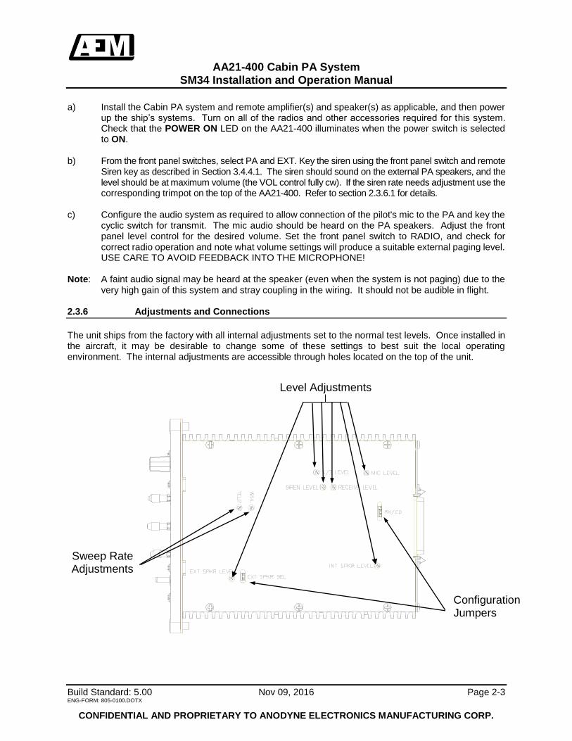
very high gain of this system and stray coupling in the wiring. It should not be audible in flight. 2.3.6 Adjustments and Connections
The unit ships from the factory with all internal adjustments set to the normal test levels. Once installed in the aircraft, it may be desirable to change some of these settings to best suit the local operating environment. The internal adjustments are accessible through holes located on the top of the unit.
Sweep Rate Adjustments
Configuration Jumpers
Level Adjustments

AA21-400 Cabin PA System
SM34 Installation and Operation Manual
Build Standard: 5.00 Nov 09, 2016 Page 2-4 ENG-FORM: 805-0100.DOTX
CONFIDENTIAL AND PROPRIETARY TO ANODYNE ELECTRONICS MANUFACTURING CORP.
2.3.6.1 Sweep Rate
The sweep rates for the wail and yelp modes of the siren are adjustable using the appropriately marked pots. The yelp rate is adjustable from 48 cycles/min to 300 cycles/min, and the wail rate is adjustable from 5 cycles/min to 200 cycles/min. Rotating a pot cw will increase the sweep rate, and ccw will decrease it. 2.3.6.2 Level Adjustments
The sidetone, mic, siren, receive, and internal speaker levels are all adjustable by rotating the appropriate pots cw to increase the level, and ccw to decrease it. The external speaker level is adjustable by rotating the appropriate pot cw to decrease the level, and ccw to increase it. The range adjustments for the potentiometers are given below:
External speaker level: (60dB dynamic range)
Internal speaker level: (90dB dynamic range)
S/T level: (100dB dynamic range)
Mic level: (60dB dynamic range)
Receive level: (70dB dynamic range)
Siren level: (70dB dynamic range) 2.3.6.3 Configuration Jumpers
The configuration options for the AA21-400 can be selected by installing jumpers as shown below: RX/CD: Pins 1-2 : Radio (Receive) input enabled, CD input disabled Pins 2-3 : CD input enabled, Radio (Receive) input disabled EXT SPKR LEVEL : Installed : 500 mVrms output level
Not installed : 6.5 Vrms output level
2.4 Continued Airworthiness
Maintenance of the AA21-400 is ‘on condition’ only. Periodic maintenance of this product is not required.

AA21-400 Cabin PA System
SM34 Installation and Operation Manual
Build Standard: 5.00 Nov 09, 2016 Page 2-5 ENG-FORM: 805-0100.DOTX
CONFIDENTIAL AND PROPRIETARY TO ANODYNE ELECTRONICS MANUFACTURING CORP.
2.5 Installation Drawings
DRAWING REV. DESCRIPTION TYPE SERIAL #
AA21-400-403-0 1.02 Cabin PA System Interconnect All
AA21-400-405-0 1.01 Cabin PA System Connector Map All
AA21-400-521-0 1.21 Cabin PA System Environmental Qual Form 1200 and up
AA21-400-905-0 1.20 PA Controller Faceplate 066274 and up
AA21-400-905-0 1.10 PA Controller Faceplate Up to 066274
AA21-400-922-0 1.30 Cabin PA System Mech. Installation 066274 and up
AA21-400-922-0 1.20 Cabin PA System Mech. Installation 042313 to 066273
AA21-400-922-0 1.11 Cabin PA System Mech. Installation 1200 to 042312
AA21-400-922-0 1.00 Cabin PA System Mech. Installation 1015 – 1199
Section 2.0 ends following above documents

SHEET:
UNLESS OTHERWISE SPECIFIED:
SCALE:
REVISIONPART No.:
APAPER SIZE:
TITLE:
NAME DATE
CHECKED
DRAWN
FINISH:
MATERIAL:
DIMENSIONS ARE IN INCHES [MM]
THE INFORMATION CONTAINED IN THISDRAWING IS THE SOLE PROPERTY OF
ANODYNE ELECTRONICS MANUFACTURING.ANY REPRODUCTION IN PART OR AS A WHOLE
WITHOUT THE WRITTEN PERMISSION OFANODYNE ELECTRONICS MANUFACTURING IS
PROHIBITED.
CAGE CODE
CONFIDENTIAL AND PROPRIETARY
APPROVED
L9015
ANODYNEELECTRONICSMANUFACTURING CORP.
KELOWNA BC CANADA(250)-763-1088
WWW.AEM-CORP.COM
DO NOT SCALE DRAWING
TOLERANCES:FRACTIONAL_____________ANGULAR_______________TWO DECIMAL PLACE____THREE DECIMAL PLACE___
±0.0625"±0.5°±0.010"±0.005"
DRAWING No.:AA21-400 1.02
N/A 1 of 1
SRK NOV 9/99
N/A
N/A
CABIN PA SYSTEMINTERCONNECT
403-0
1.01 DOCCR02739 - ADDED NOTE B. FEB 5/09 TAT1.02 ECO1054 - UPDATED TO AEM TITLEBLOCK. OCT 14/16 LAC
Oct 21, 2016
Oct 26/16

SHEET:
UNLESS OTHERWISE SPECIFIED:
SCALE:
REVISIONPART No.:
APAPER SIZE:
TITLE:
NAME DATE
CHECKED
DRAWN
FINISH:
MATERIAL:
DIMENSIONS ARE IN INCHES [MM]
THE INFORMATION CONTAINED IN THISDRAWING IS THE SOLE PROPERTY OF
ANODYNE ELECTRONICS MANUFACTURING.ANY REPRODUCTION IN PART OR AS A WHOLE
WITHOUT THE WRITTEN PERMISSION OFANODYNE ELECTRONICS MANUFACTURING IS
PROHIBITED.
CAGE CODE
CONFIDENTIAL AND PROPRIETARY
APPROVED
L9015
ANODYNEELECTRONICSMANUFACTURING CORP.
KELOWNA BC CANADA(250)-763-1088
WWW.AEM-CORP.COM
DO NOT SCALE DRAWING
TOLERANCES:FRACTIONAL_____________ANGULAR_______________TWO DECIMAL PLACE____THREE DECIMAL PLACE___
±0.0625"±0.5°±0.010"±0.005"
DRAWING No.:AA21-400 1.01
N/A 1 of 1
SRK SEP 10/99
N/A
N/A
CABIN PA SYSTEMCONNECTOR MAP
405-0
1.01 ECO1054 - UPDATED TO AEM TITLEBLOCK. OCT 14/16 LAC
Oct 21, 2016
Oct 26/16

ENVIRONMENTAL QUALIFICATION FORM
Description: Cabin PA System Document: AA21-400-521-0
Part #: AA21-4xx TSO #: C50c Manufacturer’s Specification and/or Other Applicable Specification: RTCA DO-160 Manufacturer: Anodyne Electronics Manufacturing Corp. Address: #15 - 1925 Kirschner Rd., Kelowna, BC, Canada. V1Y 4N7 DO-160 Rev: D
Prepared By: Checked By: Approved By:
Rev: 1.21 Oct 17, 2016 Page 1 of 3 ENG-FORM: 521-0100.DOTX
CONFIDENTIAL AND PROPRIETARY TO ANODYNE ELECTRONICS MANUFACTURING CORP.
Conditions Section Description of Conducted Tests
Temperature and Altitude Low Temperature High Temperature Altitude
4.0 4.5.1 4.5.2 & 4.5.3 4.6.1
Equipment tested to Category B4 -30C Operating Low Temperature +55C Operating High Temperature +70C Short-term Operating High Temperature See Remark (2)
Temperature Variation
5.0
Equipment tested to Category B
Humidity
6.0
Equipment tested to Category A
Shock Operational Crash Safety
7.0 7.2 7.3
Equipment tested to Category B Test Procedure 1, Alternate Test Procedure
(Impulse) Test Procedure 2 (Sustained), Unknown or
Random orientation in aircraft. Vibration
8.0
Equipment tested to categories SBM, UF
Explosion Proofness
9.0
Equipment identified as Category X no test
required
Waterproofness
10.0
Equipment identified as Category X no test
required
Tony Pearson DesignerOct 17, 2016
Steve Kempf DesignerOct 21/16
Todd Blackstock R&D Manager Oct 26/16

AA21-4xx Environmental Qualification Form
Rev: 1.21 Oct 17, 2016 Page 2 of 3 ENG-FORM: 521-0100.DOTX
CONFIDENTIAL AND PROPRIETARY TO ANODYNE ELECTRONICS MANUFACTURING CORP.
Conditions Section Description of Conducted Tests
Fluids Susceptibility
11.0
Equipment identified as Category X no test
required
Sand and Dust
12.0
Equipment identified as Category X no test
required
Fungus Resistance
13.0
Equipment identified as Category X no test
required
Salt Spray
14.0
Equipment identified as Category X no test
required
Magnetic Effect
15.0
Equipment is Class Z
Power input
16.0
Equipment tested to Category B
Voltage Spike
17.0
Equipment tested to Category A
Audio Frequency Susceptibility
18.0
Equipment tested to Category B
Induced Signal Susceptibility
19.0
Equipment tested to Category B
Radio Frequency Susceptibility
20.0
Equipment tested to Category TTX
Radio Frequency Emission
21.0
Equipment tested to Category M
Lightning Induced Transient Susceptibility
22.0
Equipment identified as Category X no test
required
Lightning Direct Effects test
23.0
Equipment identified as Category X no test
required
Icing
24.0
Equipment identified as Category X no test
required
Electrostatic Discharge (ESD)
25.0
Equipment identified as Category X no test
required

AA21-4xx Environmental Qualification Form
Rev: 1.21 Oct 17, 2016 Page 3 of 3 ENG-FORM: 521-0100.DOTX
CONFIDENTIAL AND PROPRIETARY TO ANODYNE ELECTRONICS MANUFACTURING CORP.
REMARKS (1) Tests were conducted at Northern Airborne Technology Ltd. (2) AA21-401 was tested to 55,000 ft.
End of Environmental Qualification Form

SHEET:
UNLESS OTHERWISE SPECIFIED:
SCALE:
REVISIONPART No.:
APAPER SIZE:
TITLE:
NAME DATE
CHECKED
DRAWN
FINISH:
MATERIAL:
DIMENSIONS ARE IN INCHES [MM]
THE INFORMATION CONTAINED IN THISDRAWING IS THE SOLE PROPERTY OF
ANODYNE ELECTRONICS MANUFACTURING.ANY REPRODUCTION IN PART OR AS A WHOLE
WITHOUT THE WRITTEN PERMISSION OFANODYNE ELECTRONICS MANUFACTURING IS
PROHIBITED.
CAGE CODE
CONFIDENTIAL AND PROPRIETARY
APPROVED
L9015
ANODYNEELECTRONICSMANUFACTURING CORP.
KELOWNA BC CANADA(250)-763-1088
WWW.AEM-CORP.COM
DO NOT SCALE DRAWING
TOLERANCES:FRACTIONAL_____________ANGULAR_______________TWO DECIMAL PLACE____THREE DECIMAL PLACE___
±0.0625"±0.5°±0.010"±0.005"
DRAWING No.:AA21-400 1.20
1:1 1 of 3
MWS JUL 30/99
N/A
N/A
PA CONTROLLERFACEPLATE
905-0
1.10 DOCCR01643 - "B" HOLE WAS "G"HOLE,MAY 26/06 TAT"E" HOLES WERE "A" HOLES, FORMAT CHANGES.
1.20 ECO1054 - UPDATED TO AEM FORMAT AND REMOVED NAT LOGO. OCT 27/16 LAC
27-Oct-1627-Oct-2016


6.33"±
0.03"
[160.8
mm
±0.8m
m]
0.95"±
0.03"
[24.1m
m±0
.8mm
]
3.45"
[87.6m
m]
2.42" [61.5mm]4.96"±0.03" [126.0mm±0.8mm]
0.57" [14.5mm]
7.48"±
0.05"
[189.9
mm
±1.27
mm
]
CENTER OF GRAVITY ±0.05
5.75"±0.03" [146.1mm±0.8mm]
1.11"±
0.03"
[28.1m
m±0
.8mm
]
NOTES:1. WEIGHT: 1.30 lbs. (0.59kg) + 0.10 (0.045 kg) MAX
- 0.25 (0.113 kg) MIN
SHEET:
UNLESS OTHERWISE SPECIFIED:
SCALE: DRAWING No.:
REVISIONPART No.:
BPAPER SIZE:
TITLE:
NAME DATE
CHECKED
DRAWN
FINISH:
MATERIAL:
DIMENSIONS ARE IN INCHES [MM]
THE INFORMATION CONTAINED IN THISDRAWING IS THE SOLE PROPERTY OF
ANODYNE ELECTRONICS MANUFACTURING.ANY REPRODUCTION IN PART OR AS A WHOLE
WITHOUT THE WRITTEN PERMISSION OFANODYNE ELECTRONICS MANUFACTURING IS
PROHIBITED.
CAGE CODE
CONFIDENTIAL AND PROPRIETARY
APPROVED
L9015
ANODYNEELECTRONICSMANUFACTURING CORP.
KELOWNA BC CANADA(250)-763-1088
WWW.AEM-CORP.COM
DO NOT SCALE DRAWING
TOLERANCES:FRACTIONAL_____________ANGULAR_______________TWO DECIMAL PLACE____THREE DECIMAL PLACE___
±0.0625"±0.5°±0.010"±0.005"
AA21-400 1.30922-01:1 1 of 1
MWS DEC 7/99
N/A
N/A
CABIN PA SYSTEMMECHANICAL INSTALLATION
21-Oct-16Oct 21/16


AA21-400 Cabin PA System
SM34 Installation and Operation Manual
Build Standard: 5.00 Nov 09, 2016 Page 3-1 ENG-FORM: 806-0100.DOTX
CONFIDENTIAL AND PROPRIETARY TO ANODYNE ELECTRONICS MANUFACTURING CORP.
Section 3.0 Operation
3.1 Introduction
Information in this section consists of the functional and operational procedures for the AA21-400 Cabin PA system.
3.2 Operation Specifics
The AA21-400 Cabin PA system provides a central adjustment for internal and/or external aircraft paging functions. The AA21-400 is a self-contained amplifier that directly drives the cabin speaker(s) and/or the external PA system amplifier. When turned on, the system is ready for operation and will accept audio feeds or a microphone input. An internally generated siren is also available in WAIL or YELP modes. When the AA21-400 is turned on, a 28 Vdc switched signal is generated. This signal is used to turn on the PA amp relay (if connected in system). The high current DC power to operate the PA110/220 or PA250/700 is supplied by the aircraft.
3.3 Techniques of Voice Transmission
To successfully project the human voice over long distances, it is necessary to develop a microphone technique different from the usual conversational manner. Place the microphone with the upper lip touching the mouthpiece and talk clearly and distinctly, with increased emphasis. Separate each word with noticeable pauses and keep the voice level constant. A medium pitched voice is more easily understood and carries farther than a bass voice.
3.4 Basic Operation
3.4.1 Power Up To activate the AA21-400 Cabin PA system, flip the POWER toggle switch up to the ON position. The LED adjacent to the switch should illuminate.
Power Switch Indicator LED

AA21-400 Cabin PA System
SM34 Installation and Operation Manual
Build Standard: 5.00 Nov 09, 2016 Page 3-2 ENG-FORM: 806-0100.DOTX
CONFIDENTIAL AND PROPRIETARY TO ANODYNE ELECTRONICS MANUFACTURING CORP.
3.4.2 Input Function Selection The Input Function switch is a two-position, locking switch on the front of the AA21-400 that is used to select between PA and Radio operation. When PA is selected, RADIO is disabled, and vice versa. It is good practice to set this switch to PA when operating the siren to avoid mixing incoming radio/CD audio with the siren audio output.
Input Function Switch
3.4.2.1 PA Operation For external PA/Siren systems or internal paging functions, set the function switch on the AA21-400 to PA. Key the microphone through the cyclic or hand mic switch, and speak in a firm, clear manner. 3.4.2.2 Radio Operation To set the system for radio rebroadcast functions, set the function switch on the AA21-400 to RADIO. All audio delivered from the source (typically pilot’s or copilot’s headset) will be broadcast from the PA system or internal speaker.
3.4.3 Volume Control
Volume Control
The volume control knob (VOL) on the front of the AA21-400 is used to adjust the level of the selected output. Rotating the knob clockwise will increase the volume, and counter-clockwise will decrease it. For external paging and rebroadcast operations, the volume should always be set between half and full level. The setting for internal paging must be determined by experiment to provide the desired coverage in the passenger area and to prevent feedback.

AA21-400 Cabin PA System
SM34 Installation and Operation Manual
Build Standard: 5.00 Nov 09, 2016 Page 3-3 ENG-FORM: 806-0100.DOTX
CONFIDENTIAL AND PROPRIETARY TO ANODYNE ELECTRONICS MANUFACTURING CORP.
3.4.4 Mode Switches
Siren Mode Switch
Internal/External Mode Switch
3.4.4.1 Siren Mode The siren mode switch is a three position, centre-off locking switch on the front of the AA21-400. The siren is operated by selecting the mode (YELP or WAIL) and then activating a remote Siren key. The siren will sound only as long as the mode is selected to WAIL or YELP and the Siren key is activated. It should be noted that in some installations, the remote Siren key is connected directly to ground. In this case, the siren will sound as soon as either YELP or WAIL is selected. Note: Siren audio is only available when the INT/EXT switch is selected to EXT. (See section 3.4.4.2.) 3.4.4.2 Internal/External Mode Switch
The INT/EXT mode switch is a two position locking switch that routes the selected audio either to the internal 8 speaker (INT) or to the PA via an amplifier such as the PA250/700 or PA110/220 (EXT).
3.4.5 Remote Power Switch The AA21-400 provides a switched 28 Vdc low current output that is typically used to control the dc power circuit of an PA110, PA220, PA250 or PA700. Note: This output is only available when the power switch is in the ON position.
End of Section 3.0