AA T3683 Batter yManager 1A Linear Li-Ion Batte ry … T3683 Batter yManager TM 1A Linear Li-Ion...
22
AAT3683 1A Linear Li-Ion Battery Charger BatteryManager TM PRODUCT DATASHEET 3683.2011.08.1.5 1 www.analogictech.com General Description The AAT3683 BatteryManager is a highly integrated sin- gle-cell lithium-ion / polymer (Li-Ion) battery charger that operates from a USB port or an AC adapter input up to an input voltage of 7.5V. The AAT3683 precisely regulates battery charge voltage and current for 4.2V Li-Ion battery cells. The battery charging current can be set by an external resistor up to 1A. Digital Thermal Loop Control maintains the maximum possible battery charging current for the given set of input to output power dissipation and ambient tempera- ture conditions. Battery charge state is continuously monitored for fault conditions. In the event of an over-current, over-voltage, short-circuit, or over-temperature condition, the device will shut down automatically, thus protecting the charg- ing device, control system, and the battery under charge. A status monitor output pin is provided to indi- cate the battery charge status by directly driving an external LED. An open-drain power source detection out- put is provided to report the power supply status. The AAT3683 is available in the Pb-free, thermally- enhanced, space-saving 2.2x2.2mm 10-pin STDFN (AAT3683-2) and 16-pin QFN33 (AAT3683-4) packages and is specified for operation over the -40°C to +85°C temperature range. Features • USB or AC Adapter Input • Programmable from 100mA to 1A • 4.0V to 7.5V Input Voltage Range • High Level of Integration with Internal: ▪ Charging Device ▪ Reverse Blocking Diode ▪ Current Sensing • Digital Thermal Regulation • Charge Current Programming (ISET) • Charge Termination Current Programming (TERM) • Charge Timer (CT) • Battery Temperature Sensing (TS) • TS Pin Open Detection • Automatic Recharge Sequencing • Automatic Trickle Charge for Battery Pre-Conditioning (no trickle charge option available) • Full Battery Charge Auto Turn-Off / Sleep Mode / Charge Termination • 1µA Max. Shutdown Current • Over-Voltage and Over-Current Protection • Emergency Thermal Protection • Power On Reset and Soft Start • 2.2x2.2mm STDFN-10 (AAT3863-2) and QFN33-16 (AAT3683-4) Packages Applications • Bluetooth Headsets, Headphones, Accessories • Cellular Phones • Digital Still Cameras • MP3, Portable Music, and Portable Media Players • Personal Data Assistants (PDAs) and Handheld Computers • Other Li-Ion Battery-Powered Devices Typical Application VIN RTERM ADPP# ENABLE EN TERM GND BAT STAT RSET ISET IN AAT3683-2 BATT- TEMP Battery Pack BATT+ BATT TEMP Battery Pack BATT+ TS CBAT CIN CT CT RTERM STAT2 EN TERM BAT STAT1 IN AAT3683-4 BATT- TEMP Battery Pack BATT+ BATT- TEMP Battery Pack BATT+ TS CBAT RT VIN ENABLE CIN GND RSET ISET CT CT
Transcript of AA T3683 Batter yManager 1A Linear Li-Ion Batte ry … T3683 Batter yManager TM 1A Linear Li-Ion...

AAT36831A Linear Li-Ion Battery ChargerBatteryManagerTM
PRODUCT DATASHEET
3683.2011.08.1.5 1w w w . a n a l o g i c t e c h . c o m
General DescriptionThe AAT3683 BatteryManager is a highly integrated sin-gle-cell lithium-ion / polymer (Li-Ion) battery charger that operates from a USB port or an AC adapter input up to an input voltage of 7.5V.
The AAT3683 precisely regulates battery charge voltage and current for 4.2V Li-Ion battery cells. The battery charging current can be set by an external resistor up to 1A.
Digital Thermal Loop Control maintains the maximum possible battery charging current for the given set of input to output power dissipation and ambient tempera-ture conditions.
Battery charge state is continuously monitored for fault conditions. In the event of an over-current, over-voltage, short-circuit, or over-temperature condition, the device will shut down automatically, thus protecting the charg-ing device, control system, and the battery under charge. A status monitor output pin is provided to indi-cate the battery charge status by directly driving an external LED. An open-drain power source detection out-put is provided to report the power supply status.
The AAT3683 is available in the Pb-free, thermally-enhanced, space-saving 2.2x2.2mm 10-pin STDFN (AAT3683-2) and 16-pin QFN33 (AAT3683-4) packages and is specified for operation over the -40°C to +85°C temperature range.
Features• USBorACAdapterInput• Programmablefrom100mAto1A• 4.0Vto7.5VInputVoltageRange• HighLevelofIntegrationwithInternal: Charging Device ReverseBlockingDiode Current Sensing
• DigitalThermalRegulation• ChargeCurrentProgramming(ISET)• ChargeTerminationCurrentProgramming(TERM)• ChargeTimer(CT)• BatteryTemperatureSensing(TS)• TSPinOpenDetection• AutomaticRechargeSequencing• AutomaticTrickleChargeforBatteryPre-Conditioning
(no trickle charge option available)• FullBatteryChargeAutoTurn-Off/SleepMode/
Charge Termination• 1µAMax.ShutdownCurrent• Over-VoltageandOver-CurrentProtection• EmergencyThermalProtection• PowerOnResetandSoftStart• 2.2x2.2mmSTDFN-10(AAT3863-2)andQFN33-16
(AAT3683-4) Packages
Applications• BluetoothHeadsets,Headphones,Accessories• CellularPhones• DigitalStillCameras• MP3,PortableMusic,andPortableMediaPlayers• PersonalDataAssistants(PDAs)andHandheld
Computers• OtherLi-IonBattery-PoweredDevices
Typical Application
VIN
RTERM
ADPP#
ENABLE
EN
TERM
GND
BAT
STAT
RSET
ISET
IN
AAT3683-2
BATT-
TEMP
BatteryPack
BATT+
BATT
TEMP
BatteryPack
BATT+
TS
CBATCIN
CT
CT
RTERM
STAT2
EN
TERM
BAT
STAT1
IN
AAT3683-4
BATT-
TEMP
BatteryPack
BATT+
BATT-
TEMP
BatteryPack
BATT+
TS
CBAT
RT
VIN
ENABLE
CIN
GNDRSET
ISETCT
CT
AAT36831A Linear Li-Ion Battery ChargerBatteryManagerTM
PRODUCT DATASHEET
2 3683.2011.08.1.5w w w . a n a l o g i c t e c h . c o m
AAT36831A Linear Li-Ion Battery ChargerBatteryManagerTM
PRODUCT DATASHEET
2 3683.2011.08.1.5w w w . a n a l o g i c t e c h . c o m
Pin Descriptions
PinName Type Function
AAT3683-2 AAT3683-41 n/a STAT
OCharge status pin, open drain.
n/a 16 STAT1 Charge status pin, open drain.
2 2 TERMI
Charge termination current programming input pin (internal default 10% terminationcurrentifTERMisopen).
3 3 GND Ground.4 4 CT Charge timer programming input pin (no timer if grounded).5 n/a ADPP#
OInput supply power-good status pin, open drain.
n/a 5 STAT2 Charge status pin, open drain.
6 7 TS I/O Battery temperature sense pin. (Leave this TS pin open to disable this function in AAT3683-2).
7 6 BAT O Connect to Li-Ion battery.8 15 IN
IInput from USB port/AC adapter connector.
9 11 ISET Charge current programming input pin.10 12 EN Active high enable pin (with internal pull-down).
n/a 1, 8, 9, 10, 13, 14 N/C Not connected.
EP Exposed paddle (bottom); connect to ground as closely as possible to the device.
Pin Configuration
AAT3683-2 AAT3683-4 STDFN2.2x2.2-10 QFN33-16 (Top View) (Top View)
GND
ADPP#
CT
STAT
TERM
IN
TS
BAT
EN
ISET
3
4
5
1
2
8
7
6
10
9
EN
ISET
N/C
ST
AT
1
N/C
TERM
GND
1
2
3
4
BA
T
ST
AT
2
TS
16
15
14
13
5 6 7 8
12
11
10
9
N/C
N/C
N/C
N/CIN
CT

AAT36831A Linear Li-Ion Battery ChargerBatteryManagerTM
PRODUCT DATASHEET
3683.2011.08.1.5 3w w w . a n a l o g i c t e c h . c o m
AAT36831A Linear Li-Ion Battery ChargerBatteryManagerTM
PRODUCT DATASHEET
3683.2011.08.1.5 3w w w . a n a l o g i c t e c h . c o m
AAT3683 Feature Options
Product Battery Temperature Sense Status Indicator DisplayAAT3683-2 For Use With 10kW NTC Thermistor 1 LEDAAT3683-4 For Use With Any Thermistor 2 LEDs
Absolute Maximum Ratings1
Symbol Description Value UnitsVIN IN Continuous -0.3 to 8.0
VVN BAT, STAT, ADPP#, EN, ISET, TS, STAT1, STAT2 -0.3 to VIN + 0.3TJ JunctionTemperatureRange -40 to 150
°CTLEAD Maximum Soldering Temperature (at Leads) 300TA OperatingTemperatureRange -40 to 85
Thermal Information2
Symbol Description Value Units
ΘJA ThermalResistanceSTDFN2.2x2.2-10
50 °C/WQFN33-16
PD Maximum Power Dissipation (TA = 25°C)STDFN2.2x2.2-10
2 WQFN33-16
1.StressesabovethoselistedinAbsoluteMaximumRatingsmaycausepermanentdamagetothedevice.Functionaloperationatconditionsotherthantheoperatingconditionsspecified is not implied.
2.MountedonanFR4board.

AAT36831A Linear Li-Ion Battery ChargerBatteryManagerTM
PRODUCT DATASHEET
4 3683.2011.08.1.5w w w . a n a l o g i c t e c h . c o m
AAT36831A Linear Li-Ion Battery ChargerBatteryManagerTM
PRODUCT DATASHEET
4 3683.2011.08.1.5w w w . a n a l o g i c t e c h . c o m
Electrical Characteristics VIN = 5V, TA = -40°C to +85°C, unless otherwise noted. Typical values are at TA = 25°C.
Symbol Description Conditions Min Typ Max UnitsOperation
VIN InputVoltageRange 4.0 7.5V
VUVLOUnder-Voltage Lockout Threshold RisingEdge 3 4UVLOHysteresis 150
mVVADPP_TH
Adapter Present Indicator Threshold Voltage, VIN - VBA
VIN > VUVLO 60 110
IOP OperatingCurrent Charge Current = 100mA 0.31
mAISHUTDOWN Shutdown Current VBAT = 4.25V, EN = GND
0.4 µAILEAKAGE Leakage Current from BAT Pin VBAT=4V,INPinOpen 2
Voltage RegulationVBAT_EOC End of Charge Accuracy 4.158 4.20 4.242 VDVBAT_EOC/ VBAT_EOC
End of Charge Tolerance 0.5 %
VMIN Preconditioning Voltage Threshold (Optionavailablefornotricklecharge) 2.5 2.6 2.7V
VRCH BatteryRechargeVoltageThreshold VBAT_EOC - 0.1
Current RegulationICC_RANGE ChargeCurrentProgrammableRange 100 1000 mAICH_CC Constant Current Mode Charge Current VIN = 6.5V and VBAT = 3.6V -12.5 12.5 %VISET ISET Pin Voltage 2 VKISET ChargeCurrentSetFactor:ICH_CC/IISET Constant Current Mode, VBAT = 3.6V 800VTERM TERMPinVoltage RTERM = 13.3KW 0.2 V
ICH_TRK Trickle-Charge Current 510
15 % ICH_CCTERMPinOpenICH_TERM Charge Termination Threshold Current RTERM = 13.3KW, ICH_CC ≥ 800mA 8 12 %
Charging DevicesRDS(ON) ChargingTransistorOnResistance VIN = 5V 0.5 0.7 W

AAT36831A Linear Li-Ion Battery ChargerBatteryManagerTM
PRODUCT DATASHEET
3683.2011.08.1.5 5w w w . a n a l o g i c t e c h . c o m
AAT36831A Linear Li-Ion Battery ChargerBatteryManagerTM
PRODUCT DATASHEET
3683.2011.08.1.5 5w w w . a n a l o g i c t e c h . c o m
Electrical Characteristics VIN = 5V, TA = -40°C to +85°C, unless otherwise noted. Typical values are at TA = 25°C.
Symbol Description Conditions Min Typ Max UnitsLogic Control / Protection
VEN(H) InputHighThreshold 1.6VVEN(L) Input Low Threshold 0.4
VSTAT OutputLowVoltage STAT Pin Sinks 4mA 0.2ISTAT STAT Pin Current Sink Capability 8 mA
VADDP# OutputLowVoltage ADPP# Pin Sinks 4mA 0.2 VIADPP# ADDP# Pin Current Sink Capability 8 mAVOVP Over-VoltageProtectionThreshold 4.4 VIOCP Over-CurrentProtectionThreshold 105 %ICH_CCTK Trickle Timeout
CT=0.1µF,VIN = 5V25 Minute
TC Trickle and Constant Current Mode Timeout3 Hour
TV Constant Voltage Mode TimeoutITS Current Source from TS Pin AAT3683-2Only 69 75 81 µA
TS1 TSHotTemperatureFaultThreshold,AAT3683-2Only 316 331 346
mVHysteresis,AAT3683-2Only 25
TS2 TS Cold Temperature Fault Threshold,AAT3683-2Only 2.30 2.39 2.48 VHysteresis,AAT3683-2Only 25 mV
VTS1 HighTemperatureThresholdAAT3683-4Only
29.1 30 30.9%VINVTS2 Low Temperature Threshold 58.2 60 61.8
TLOOP_IN Thermal Loop Entering Threshold 115
ºCTLOOP_OUT Thermal Loop Exiting Threshold 85
TREG ThermalLoopRegulation 100
TSHDN Over-TemperatureShutdownThreshold 140Hysteresis 15
AAT36831A Linear Li-Ion Battery ChargerBatteryManagerTM
PRODUCT DATASHEET
6 3683.2011.08.1.5w w w . a n a l o g i c t e c h . c o m
AAT36831A Linear Li-Ion Battery ChargerBatteryManagerTM
PRODUCT DATASHEET
6 3683.2011.08.1.5w w w . a n a l o g i c t e c h . c o m
Typical Characteristics
Constant Charging Current
vs. Set Resistor Values
RSET (kΩ)
CC
Mo
de C
harg
e C
urr
en
t (m
A)
10
100
1000
10000
1 10 100
Charging Current vs. Battery Voltage
VBAT (V)
I CH (
mA
)
0
200
400
600
800
1000
1200
2.5 2.7 2.9 3.1 3.3 3.5 3.7 3.9 4.1 4.3
RSET
= 1.58k
RSET
= 2k
RSET
= 3.24k
RSET
= 8.06k
End of Charge Regulation Accuracy
vs. Input Voltage (VBAT_EOC = 4.2V)
Input Voltage (V)
∆VB
AT
_E
OC/V
BA
T_E
OC (
%)
-0.20
-0.15
-0.10
-0.05
0.00
0.05
0.10
0.15
0.20
4.5 5.0 5.5 6.0 6.5 7.0 7.5
End of Charge Voltage vs. Temperature
Temperature (°C)
VE
OC (
V)
4.180
4.190
4.200
4.210
4.220
-50 -25 0 25 50 75 100
Preconditioning Charge Current
vs. Input Voltage
Input Voltage (V)
I CH
_T
RK (
mA
)
0
20
40
60
80
100
120
4 4.5 5 5.5 6 6.5 7 7.5
RSET
= 1.58k
RSET
= 2k
RSET
= 3.24k
RSET
= 8.06k
Preconditioning Voltage Threshold
vs. Temperature
Temperature (°C)
VM
IN (
V)
VIN = 2.7VVIN = 3.6V
VIN = 4.2V
2.4
2.45
2.5
2.55
2.6
2.65
2.7
-40 -15 10 35 60 85

AAT36831A Linear Li-Ion Battery ChargerBatteryManagerTM
PRODUCT DATASHEET
3683.2011.08.1.5 7w w w . a n a l o g i c t e c h . c o m
AAT36831A Linear Li-Ion Battery ChargerBatteryManagerTM
PRODUCT DATASHEET
3683.2011.08.1.5 7w w w . a n a l o g i c t e c h . c o m
Typical Characteristics
Preconditioning Charge Current vs. Temperature(RSET = 8.06k; ICH_CC = 200mA)
Temperature (°C)
Pre
co
nd
itio
nin
g
Ch
arg
e C
urr
en
t (m
A)
17
18
19
20
21
22
23
-40 -15 10 35 60 85
Battery Recharge Voltage
Threshold vs. Temperature
Temperature (°C)
VR
CH (
V)
4.04
4.06
4.08
4.10
4.12
4.14
-40 -15 10 35 60 85
Constant Charging Current vs. Input Voltage(RSET = 1.58KΩ)
Input Voltage (V)
Co
nsta
nt
Ch
arg
ing
Cu
rren
t (m
A)
700
750
800
850
900
950
1000
1050
1100
4.0 4.5 5.0 5.5 6.0 6.5 7.0 7.5
VBAT = 3.3V
VBAT = 3.5V
VBAT = 3.9V
Temperature Sense Output Current
vs. Temperature (AAT3683-2 Only)
Temperature (°C)
I TS (
µA
)
68.0
70.0
72.0
74.0
76.0
78.0
-40 -15 10 35 60 85
Temperature Sense Too Hot Threshold
vs. Temperature (AAT3683-2 Only)
Temperature (°C)
Tem
pera
ture
Sen
se
Th
resh
old
Vo
ltag
e -
TS
1 (
V)
0.320
0.325
0.330
0.335
0.340
0.345
-40 -15 10 35 60 85
Temperature Sense Too Cold Threshold
vs. Temperature (AAT3683-2 Only)
Temperature (°C)
Tem
pera
ture
Sen
se
Th
resh
old
Vo
ltag
e-
TS
2 (
V)
2.37
2.38
2.39
2.40
2.41
2.42
-40 -15 10 35 60 85
AAT36831A Linear Li-Ion Battery ChargerBatteryManagerTM
PRODUCT DATASHEET
8 3683.2011.08.1.5w w w . a n a l o g i c t e c h . c o m
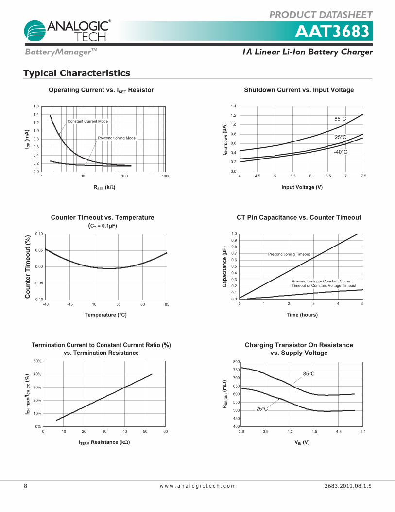
Typical Characteristics
Operating Current vs. ISET Resistor
RSET (kΩ)
I OP (
mA
)
0.0
0.2
0.4
0.6
0.8
1.0
1.2
1.4
1.6
1 10 100 1000
Preconditioning Mode
Constant Current Mode
Shutdown Current vs. Input Voltage
Input Voltage (V)
I SH
UT
DO
WN (
µA
)85°C
25°C
-40°C
0.0
0.2
0.4
0.6
0.8
1.0
1.2
1.4
4 4.5 5 5.5 6 6.5 7 7.5
85°C
25°C
-40°C
Counter Timeout vs. Temperature
(CT = 0.1µF)
Temperature (°C)
Co
un
ter
Tim
eo
ut
(%)
-0.10
-0.05
0.00
0.05
0.10
-40 -15 10 35 60 85
CT Pin Capacitance vs. Counter Timeout
Time (hours)
Cap
acit
an
ce (
µF
)
0.0
0.1
0.2
0.3
0.4
0.5
0.6
0.7
0.8
0.9
1.0
0 1 2 3 4 5
Preconditioning Timeout
Preconditioning + Constant Current
Timeout or Constant Voltage Timeout
Termination Current to Constant Current Ratio (%)
vs. Termination Resistance
ITERM Resistance (kΩ)
I CH
_T
ER
M/I
CH
_C
C (
%)
0%
10%
20%
30%
40%
50%
0 10 20 30 40 50 60
Charging Transistor On Resistance
vs. Supply Voltage
VIN (V)
RD
S(O
N) (m
Ω)
400
450
500
550
600
650
700
750
800
3.6 3.9 4.2 4.5 4.8 5.1
85°C
25°C
AAT36831A Linear Li-Ion Battery ChargerBatteryManagerTM
PRODUCT DATASHEET
3683.2011.08.1.5 9w w w . a n a l o g i c t e c h . c o m
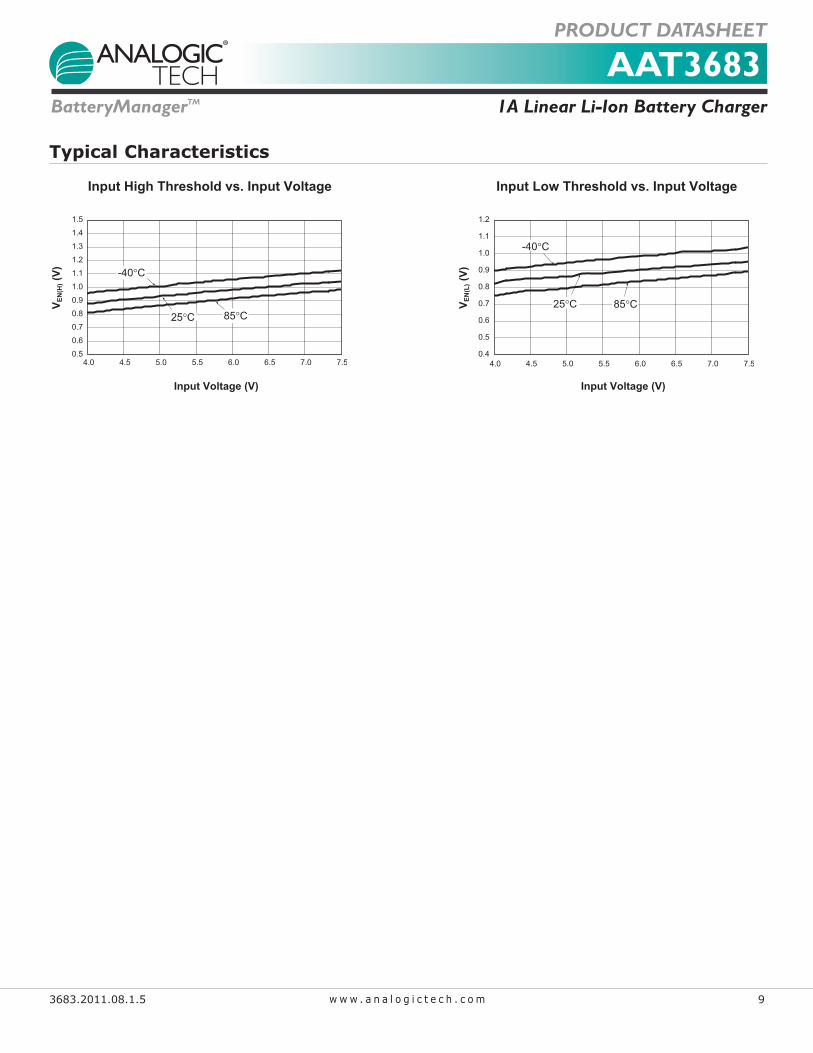
Typical Characteristics
Input High Threshold vs. Input Voltage
Input Voltage (V)
VE
N(H
) (V
)
0.5
0.6
0.7
0.8
0.9
1.0
1.1
1.2
1.3
1.4
1.5
4.0 4.5 5.0 5.5 6.0 6.5 7.0 7.5
85°C25°C
-40°C
Input Low Threshold vs. Input Voltage
Input Voltage (V)
VE
N(L
) (V
)
0.4
0.5
0.6
0.7
0.8
0.9
1.0
1.1
1.2
4.0 4.5 5.0 5.5 6.0 6.5 7.0 7.5
85°C25°C
-40°C

AAT36831A Linear Li-Ion Battery ChargerBatteryManagerTM
PRODUCT DATASHEET
10 3683.2011.08.1.5w w w . a n a l o g i c t e c h . c o m
Functional DescriptionThe AAT3683 is a high performance battery charger designed to charge single-cell lithium-ion or lithium-polymer batteries with up to 1A of current from an exter-nal power source. It is a stand-alone charging solution, withjustoneexternalcomponentrequiredforcompletefunctionality.
The AAT3683 precisely regulates battery charge voltage and current for 4.2V lithium-ion/polymer battery cells with constant current level being programmed up to 1A for rapid charging applications. The charge termination current can be programmed by an external resistor.
The AAT3683 is rated for operation from -40°C to +85°C. In the event of operating ambient temperatures exceed-ing the power dissipation abilities of the device package for a given constant current charge level, the charge control will enter into thermal limit.
AAT3683-2 provides one status monitor output pin (STAT) by directly driving one external LED to indicate
the battery charging state. AAT3683-4 provides two sta-tus pins to indicate the battery charging state.
Device junction temperature and charge state are fully monitored for fault conditions. In the event of an over-voltage or over-temperature failure, the device will auto-matically shut down, protecting the charging device, control system, and the battery under charge.
During battery charging, the device temperature will rise. In some cases with adapter (ADP) charging, the power dissipation in the device may causethe junction temperature to rise to close to its thermal shutdown threshold. In the event of an internal over-temperature condition caused by excessive ambient operating tem-perature or excessive power dissipation condition, the AAT3683 enables a digitally controlled thermal loop sys-tem that will reduce the charging current to prevent the device from thermal shutdown. The digital thermal loop will maintain the maximum possible battery charging current for the given set of input to output power dissi-pation and ambient temperature conditions.
Functional Block Diagram
Charge Control
Current Compare
Reverse Blocking
CV/ Pre-charge
Constant Current
IN BAT
ISETUVLO
Over- Temp.ProtectPower
Detection
STAT (3683-2 only)
GNDEN
Thermal Loop
ADPP#
Charge Status
Battery OV Protection
STAT1 (3683-4 only)
STAT2 (3683-4 only)
(3683-2 only)
IC EnableWatchdog
Timer
CT
75µA
TS(3683-2 only)
Window Comparator

AAT36831A Linear Li-Ion Battery ChargerBatteryManagerTM
PRODUCT DATASHEET
3683.2011.08.1.5 11w w w . a n a l o g i c t e c h . c o m
The digital thermal loop control is dynamic in the sense that it will continue to adjust the battery charging cur-rent as operating conditions change.
The digital thermal loop will reset and resume normal operation when the power dissipation or over-tempera-ture conditions are removed.
Battery Charging OperationFigure 1 illustrates the entire battery charging profile or operation,whichconsistsofthreephases:
1. Preconditioning (Trickle) Charge2. Constant Current Charge3. Constant Voltage Charge
Battery PreconditioningBattery charging commences only after the AAT3683 checks several conditions in order to maintain a safe charging environment. The input supply must be above the minimum operating voltage (VUVLO) and the enable pin must be high. When the battery is connected to the BAT pin, the AAT3683 checks the condition of the bat-tery and determines which charging mode to apply. If the battery voltage is below the preconditioning voltage threshold, VMIN, then the AAT3683 begins precondition-ing the battery cell (trickle charging) by charging at
10% of the programmed constant current. For example, if the programmed current is 500mA, then the precon-ditioning mode (trickle charge) current is 50mA. Battery cell preconditioning (trickle charging) is a safety precau-tion for deeply discharged cells and will also reduce the power dissipation in the internal series pass MOSFETwhen the input-output voltage differential is at the greatest potential.
Constant Current ChargingBattery cell preconditioning continues until the battery voltage reaches the preconditioning voltage threshold, VMIN. At this point, the AAT3683 begins constant current charging. The current level for this mode is programmed using a single resistor from the ISET pin to ground. Programmed current can be set at a minimum 100mA up to a maximum of 1A.
Constant Voltage ChargingConstant current charging will continue until such time that the battery voltage reaches the voltage regulation point, VBAT_EOC. When the battery voltage reaches VBAT_EOC, the AAT3683 will transition to constant voltage mode. The regulation voltage is factory programmed to a nom-inal 4.2V and will continue charging until the charge termination current is reached.
Constant CurrentCharge Phase
Constant VoltageCharge Phase
PreconditioningTrickle Charge
PhaseCharge Complete Voltage
Constant Current ModeVoltage Threshold
Regulated Current
Trickle Charge andTermination Threshold
I = CC / 10
I = Max CC
Figure 1: Current vs. Voltage Profile During Charging Phases.

AAT36831A Linear Li-Ion Battery ChargerBatteryManagerTM
PRODUCT DATASHEET
12 3683.2011.08.1.5w w w . a n a l o g i c t e c h . c o m
AAT36831A Linear Li-Ion Battery ChargerBatteryManagerTM
PRODUCT DATASHEET
12 3683.2011.08.1.5w w w . a n a l o g i c t e c h . c o m
System Operation Flow Chart
Power On Reset
Power Input Voltage
VIN > VUVLO
FaultConditions Monitoring
OV, OT, TS>VTS2 or TS<VTS1
Preconditioning Test
VMIN > VBAT
Current Phase TestVIN > VBAT_EOC
Voltage Phase TestIBAT > ITERM
No
No
Yes
No
Preconditioning (Trickle Charge)
Constant Current Charge
Mode
Constant Voltage Charge
Mode
Yes
Yes
Yes
Charge Completed
Charge Timer Control
No
Recharge Test VRCH > VBAT
Yes
No
Shut Down Yes
Enable
YesNo
Device Thermal Loop MonitorTJ > 115ϒC
Thermal LoopCurrent
Reduction in ADPCharging Mode
Thermal LoopCurrent
Reduction in C.C. Mode
No
Enable
Expired
Yes
AAT36831A Linear Li-Ion Battery ChargerBatteryManagerTM
PRODUCT DATASHEET
3683.2011.08.1.5 13w w w . a n a l o g i c t e c h . c o m
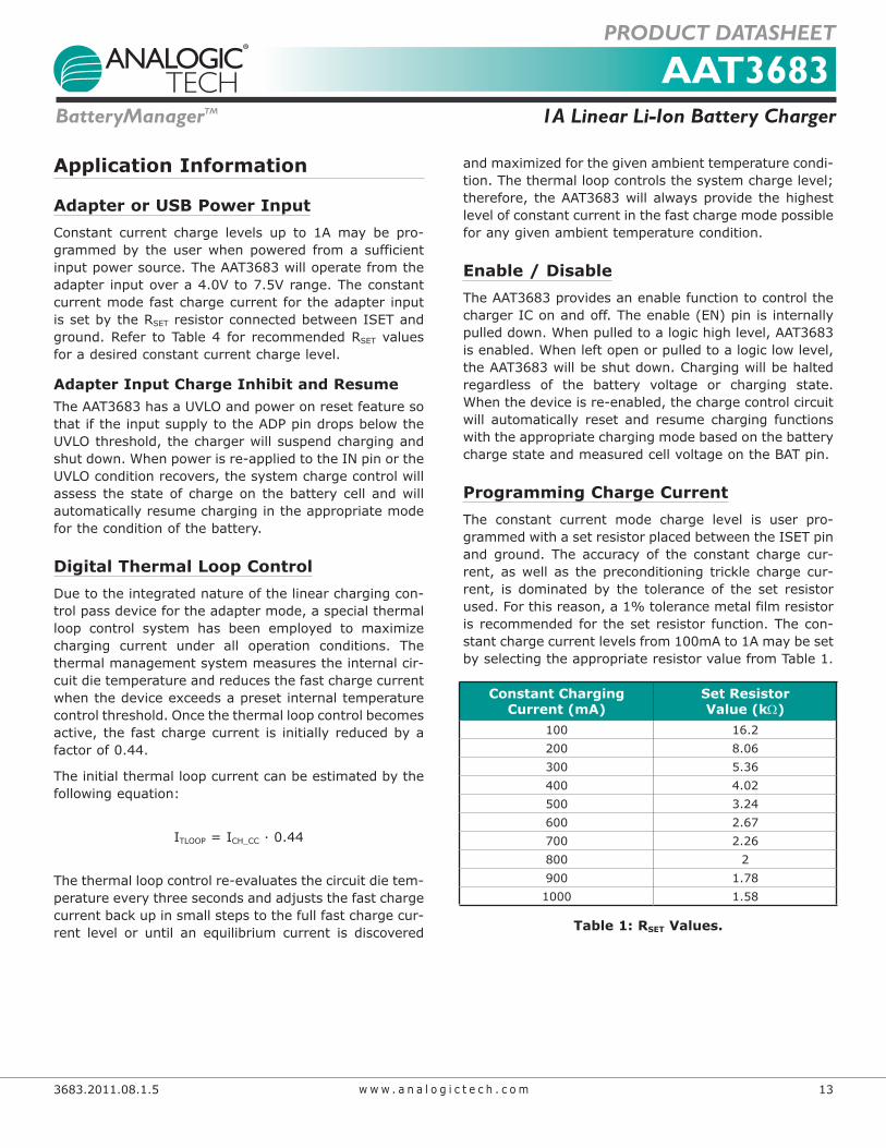
Application Information
Adapter or USB Power InputConstant current charge levels up to 1A may be pro-grammed by the user when powered from a sufficient input power source. The AAT3683 will operate from the adapter input over a 4.0V to 7.5V range. The constant current mode fast charge current for the adapter input issetbytheRSET resistor connected between ISET and ground.Refer toTable4 for recommendedRSET values for a desired constant current charge level.
Adapter Input Charge Inhibit and ResumeTheAAT3683hasaUVLOandpoweronresetfeaturesothat if the input supply to the ADP pin drops below the UVLOthreshold,thechargerwillsuspendchargingandshut down. When power is re-applied to the IN pin or the UVLOconditionrecovers,thesystemchargecontrolwillassess the state of charge on the battery cell and will automatically resume charging in the appropriate mode for the condition of the battery.
Digital Thermal Loop ControlDue to the integrated nature of the linear charging con-trol pass device for the adapter mode, a special thermal loop control system has been employed to maximize charging current under all operation conditions. The thermal management system measures the internal cir-cuit die temperature and reduces the fast charge current when the device exceeds a preset internal temperature controlthreshold.Oncethethermalloopcontrolbecomesactive, the fast charge current is initially reduced by a factor of 0.44.
The initial thermal loop current can be estimated by the followingequation:
ITLOOP = ICH_CC · 0.44
The thermal loop control re-evaluates the circuit die tem-perature every three seconds and adjusts the fast charge current back up in small steps to the full fast charge cur-rent level or until an equilibrium current is discovered
and maximized for the given ambient temperature condi-tion. The thermal loop controls the system charge level; therefore, the AAT3683 will always provide the highest level of constant current in the fast charge mode possible for any given ambient temperature condition.
Enable / DisableThe AAT3683 provides an enable function to control the charger IC on and off. The enable (EN) pin is internally pulled down. When pulled to a logic high level, AAT3683 is enabled. When left open or pulled to a logic low level, the AAT3683 will be shut down. Charging will be halted regardless of the battery voltage or charging state. When the device is re-enabled, the charge control circuit will automatically reset and resume charging functions with the appropriate charging mode based on the battery charge state and measured cell voltage on the BAT pin.
Programming Charge CurrentThe constant current mode charge level is user pro-grammed with a set resistor placed between the ISET pin and ground. The accuracy of the constant charge cur-rent, as well as the preconditioning trickle charge cur-rent, is dominated by the tolerance of the set resistor used. For this reason, a 1% tolerance metal film resistor is recommended for the set resistor function. The con-stant charge current levels from 100mA to 1A may be set by selecting the appropriate resistor value from Table 1.
Constant ChargingCurrent (mA)
Set Resistor Value (kW)
100 16.2200 8.06300 5.36400 4.02500 3.24600 2.67700 2.26800 2900 1.781000 1.58
Table 1: RSET Values.
AAT36831A Linear Li-Ion Battery ChargerBatteryManagerTM
PRODUCT DATASHEET
14 3683.2011.08.1.5w w w . a n a l o g i c t e c h . c o m
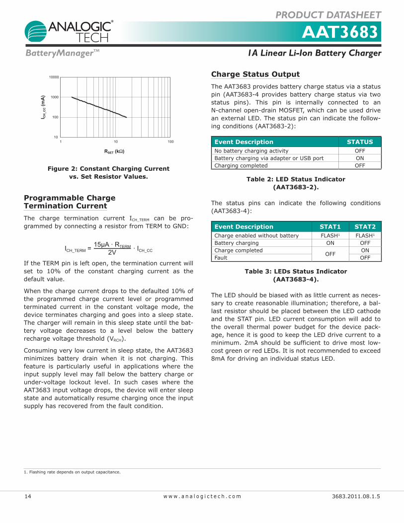
Constant Charging Current
vs. Set Resistor Values
RSET (kΩ)
I CH
_C
C (
mA
)
10
100
1000
10000
1 10 100
Figure 2: Constant Charging Current vs. Set Resistor Values.
Programmable Charge Termination CurrentThe charge termination current ICH_TERM can be pro-grammedbyconnectingaresistorfromTERMtoGND:
ICH_TERM = · ICH_CC
15µA · RTERM
2V
IftheTERMpinisleftopen,theterminationcurrentwillset to 10% of the constant charging current as the default value.
When the charge current drops to the defaulted 10% of the programmed charge current level or programmed terminated current in the constant voltage mode, the device terminates charging and goes into a sleep state. The charger will remain in this sleep state until the bat-tery voltage decreases to a level below the battery recharge voltage threshold (VRCH).
Consuming very low current in sleep state, the AAT3683 minimizes battery drain when it is not charging. This feature is particularly useful in applications where the input supply level may fall below the battery charge or under-voltage lockout level. In such cases where the AAT3683 input voltage drops, the device will enter sleep state and automatically resume charging once the input supply has recovered from the fault condition.
Charge Status OutputThe AAT3683 provides battery charge status via a status pin (AAT3683-4 provides battery charge status via two status pins). This pin is internally connected to an N-channelopen-drainMOSFET,whichcanbeuseddrivean external LED. The status pin can indicate the follow-ingconditions(AAT3683-2):
Event Description STATUSNo battery charging activity OFFBattery charging via adapter or USB port ONCharging completed OFF
Table 2: LED Status Indicator (AAT3683-2).
The status pins can indicate the following conditions (AAT3683-4):
Event Description STAT1 STAT2Charge enabled without battery FLASH1 FLASH1
Battery charging ON OFFCharge completed
OFFON
Fault OFF
Table 3: LEDs Status Indicator (AAT3683-4).
The LED should be biased with as little current as neces-sary to create reasonable illumination; therefore, a bal-last resistor should be placed between the LED cathode and the STAT pin. LED current consumption will add to the overall thermal power budget for the device pack-age, hence it is good to keep the LED drive current to a minimum. 2mA should be sufficient to drive most low-cost green or red LEDs. It is not recommended to exceed 8mA for driving an individual status LED.
1. Flashing rate depends on output capacitance.

AAT36831A Linear Li-Ion Battery ChargerBatteryManagerTM
PRODUCT DATASHEET
3683.2011.08.1.5 15w w w . a n a l o g i c t e c h . c o m
The required ballast resistor values can be estimatedusingthefollowingformula:
VIN - VF(LED)RBALLAST = ILED
Example:5.0V - 2.0VRBALLAST = = 1.5kΩ2mA
Note: Red LED forward voltage VF is typically 2.0V @ 2mA.
Protection Circuitry
Programmable Watchdog TimerThe AAT3683 contains a watchdog timing circuit to shut down charging functions in the event of a defective bat-tery cell not accepting a charge over a preset period of time.Typically,a0.1µFceramiccapacitor isconnectedbetweentheCTpinandground.Whena0.1µFceramiccapacitor is used, the device will time out a shutdown condition if the trickle charge mode exceeds 25 minutes and a combined trickle charge plus constant current mode of 3 hours. When the device transitions to the constant voltage mode, the timing counter is reset and will time out after an additional 3 hours if the charge current does not drop to the charge termination level.
The 3683-4 has a battery fault detector, which, when usedinconjunctionwitha0.1µFcapacitorontheCTpin,outputsa1Hzsignalwith50%dutycycleattheSTAT1pin in the event of a timeout while in the trickle charge mode.
Mode TimeTrickleCharge(TC)TimeOut 25 minutes
Trickle Charge (TC) + Constant Current (CC)ModeTimeOut 3 hours
ConstantVoltage(VC)ModeTimeOut
Table 4: Summary for a 0.1µF Ceramic Capacitor Used for the Timing Capacitor.
The CT pin is driven by a constant current source and will provide a linear response to increases in the timing capacitor value. Thus, if the timing capacitor were to be doubled from the nominal 0.1µF value, the time-outperiods would be doubled.
If the programmable watchdog timer function is not needed, it can be disabled by terminating the CT pin to ground. The CT pin should not be left floating or un-terminated, as this will cause errors in the internal tim-ing control circuit.
The constant current provided to charge the timing capacitor is very small, and this pin is susceptible to noise and changes in capacitance value. Therefore, the timing capacitor should be physically located on the printed circuit board layout as close as possible to the CT pin. Since the accuracy of the internal timer is domi-nated by the capacitance value, a 10% tolerance or bet-ter ceramic capacitor is recommended. Ceramic capaci-tormaterials,suchasX7RandX5Rtypes,areagoodchoice for this application.
Over-Voltage ProtectionAn over-voltage event is defined as a condition where the voltage on the BAT pin exceeds the maximum bat-tery charge voltage and is set by the over-voltage pro-tection threshold (VOVP). If an over-voltage condition occurs, the AAT3683 charge control will shut down the device until the voltage on the BAT pin drops below VOVP. The AAT3683 will resume normal charging operation after the over-voltage condition is removed. During an over-voltage event, the STAT LEDs (3683-4 only) will report a system fault.
Over-Temperature ShutdownThe AAT3683 has a thermal protection control circuit which will shut down charging functions should the inter-nal die temperature exceed the preset thermal limit threshold.Oncetheinternaldietemperaturefallsbelowthe thermal limit, normal operation will resume the pre-vious charging state.
Battery Temperature Fault MonitoringIn the event of a battery over-temperature condition, the charge control will turn off the internal pass device and report a battery temperature fault on the STAT pins. After the system recovers from a temperature fault, the device will resume charging operation.
The AAT3683-2 checks battery temperature before starting the charge cycle, as well as during all stages of charging. This is accomplished by monitoring the voltage at the TS pin. This system is intended for use with negative temperature coefficient thermistors (NTC) which are typically integrated into the battery package.

AAT36831A Linear Li-Ion Battery ChargerBatteryManagerTM
PRODUCT DATASHEET
16 3683.2011.08.1.5w w w . a n a l o g i c t e c h . c o m
Most of the commonly used NTC thermistors in battery packs are approximately 10kW at room temperature (25°C). The TS pin (3683-2 only) has been specifically designed to source 75µA of current to the thermistor.The voltage on the TS pin resulting from the resistive load should stay within a window of 331mV to 2.39V. If the battery becomes too hot during charging due to an internal fault or excessive constant charge current, the thermistor will heat up and reduce in value, pulling the TS pin voltage lower than the TS1 threshold, and the AAT3683-2 will stop charging until the condition is removed, when charging will be resumed.
IftheuseoftheTSpinfunctionisnotrequiredbythesystem, it should be terminated to ground using a 10kW resistor. Alternatively, on the AAT3683-2 only, the TS pin may be left open.
For AAT3683-4, the internal battery temperature sensing system is comprised of two comparators which establish a voltage window for safe operation. The thresholds for the TS operating window are bounded by the TS1 and TS2specifications.Referringtotheelectricalcharacteris-tics table in this datasheet, the TS1 threshold = 0.30 · VIN and the TS2 threshold = 0.60 · VIN. If the use of the TS pin function is not required on AAT3683-4, the TS pinshould be connected to input supply VIN.
0.60x VIN
x VIN
VIN
Battery Cold Fault
Battery Hot Fault
IN
TS
AAT3683-4
Battery Pack
Figure 3: AAT3683-4 Battery Temperature Sense Circuit.
Thermal ConsiderationsThe AAT3683 is offered in two packages (STDFN2.2x2.2-10 and QFN33-16) both of which can provide up to 2W of power dissipation when properly bonded to a printed circuit board and have a maximum thermal resistance of
50°C/W. Many considerations should be taken into account when designing the printed circuit board layout, as well as the placement of the charger IC package in proximity to other heat generating devices in a given application design. The ambient temperature around the charger IC will also have an effect on the thermal limits of a battery charging application. The maximum limits that can be expected for a given ambient condition can be estimated by the following discussion.
First, the maximum power dissipation for a given situa-tionshouldbecalculated:
TJ - TAPD(MAX) = ΘJA
Where:
PD(MAX) = Maximum Power Dissipation (W)ΘJA =PackageThermalResistance(°C/W)TJ = Thermal Loop Entering Threshold (ºC) [115ºC]TA = Ambient Temperature (°C)
Figure 4 shows the relationship of maximum power dis-sipation and ambient temperature of AAT3683.
TA (°C)
PD
(MA
X) (W
)
0
0.5
1
1.5
2
2.5
0 25 50 75 100
Figure 4: Maximum Power Dissipation Before Entering Thermal Loop.
Next, the power dissipation can be calculated by the fol-lowingequation:
PD = (VIN - VBAT) · ICH + VIN · IOP
Where:
PD = Total Power Dissipation by the DeviceVIN = Input Voltage VBAT = Battery Voltage as Seen at the BAT PinICH = Constant Charge Current Programmed for the
ApplicationIOP = Quiescent Current Consumed by the Charger IC
forNormalOperation[0.3mA]
AAT36831A Linear Li-Ion Battery ChargerBatteryManagerTM
PRODUCT DATASHEET
3683.2011.08.1.5 17w w w . a n a l o g i c t e c h . c o m
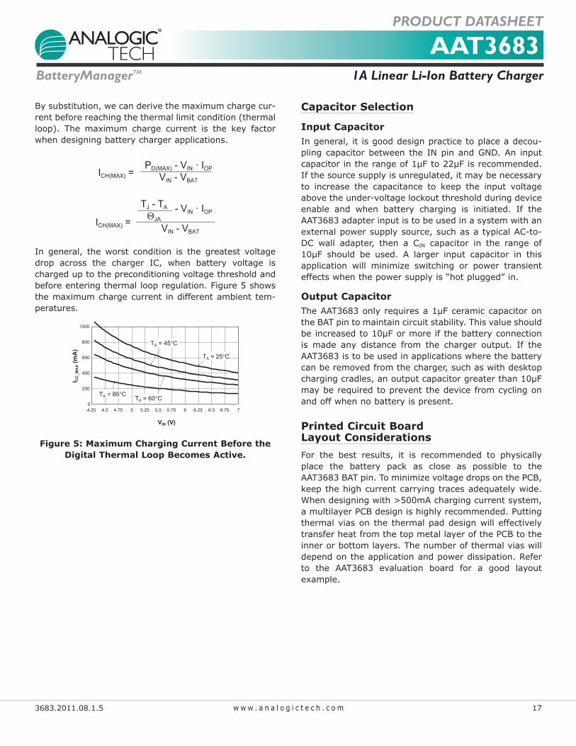
By substitution, we can derive the maximum charge cur-rent before reaching the thermal limit condition (thermal loop). The maximum charge current is the key factor when designing battery charger applications.
PD(MAX) - VIN · IOP
VIN - VBATICH(MAX) =
TJ - TA
ΘJAICH(MAX) =- VIN · IOP
VIN - VBAT
In general, the worst condition is the greatest voltage drop across the charger IC, when battery voltage is charged up to the preconditioning voltage threshold and before entering thermal loop regulation. Figure 5 shows the maximum charge current in different ambient tem-peratures.
VIN (V)
I CC
_M
AX (
mA
)
0
200
400
600
800
1000
4.25 4.5 4.75 5 5.25 5.5 5.75 6 6.25 6.5 6.75 7
TA = 85°CTA = 60°C
TA = 45°C
TA = 25°C
Figure 5: Maximum Charging Current Before the Digital Thermal Loop Becomes Active.
Capacitor Selection
Input CapacitorIn general, it is good design practice to place a decou-pling capacitor between the IN pin and GND. An input capacitorintherangeof1µFto22µFisrecommended.If the source supply is unregulated, it may be necessary to increase the capacitance to keep the input voltage above the under-voltage lockout threshold during device enable and when battery charging is initiated. If the AAT3683 adapter input is to be used in a system with an external power supply source, such as a typical AC-to-DC wall adapter, then a CIN capacitor in the range of 10µF should be used. A larger input capacitor in thisapplication will minimize switching or power transient effects when the power supply is “hot plugged” in.
Output CapacitorTheAAT3683onlyrequiresa1µFceramiccapacitoronthe BAT pin to maintain circuit stability. This value should beincreasedto10µFormoreifthebatteryconnectionis made any distance from the charger output. If the AAT3683 is to be used in applications where the battery can be removed from the charger, such as with desktop chargingcradles,anoutputcapacitorgreaterthan10µFmayberequiredtopreventthedevicefromcyclingonand off when no battery is present.
Printed Circuit Board Layout ConsiderationsFor the best results, it is recommended to physically place the battery pack as close as possible to the AAT3683 BAT pin. To minimize voltage drops on the PCB, keepthehighcurrentcarryingtracesadequatelywide.When designing with >500mA charging current system, a multilayer PCB design is highly recommended. Putting thermal vias on the thermal pad design will effectively transfer heat from the top metal layer of the PCB to the inner or bottom layers. The number of thermal vias will dependontheapplicationandpowerdissipation.Referto the AAT3683 evaluation board for a good layout example.

AAT36831A Linear Li-Ion Battery ChargerBatteryManagerTM
PRODUCT DATASHEET
18 3683.2011.08.1.5w w w . a n a l o g i c t e c h . c o m
AAT36831A Linear Li-Ion Battery ChargerBatteryManagerTM
PRODUCT DATASHEET
18 3683.2011.08.1.5w w w . a n a l o g i c t e c h . c o m
Figure 6: AAT3683-2 Evaluation Board Figure 7: AAT3683-2 Evaluation Board Top Side Layout. Middle Layer.
Figure 8: AAT3683-2 Evaluation Board Bottom Side Layout.
R3 1.5k
C110µF
C210µF
VIN
R11.58k
Enable
JP1
VBAT
STDFN2.2x2.2-10
JP2
STAT1
TERM2
GND3
CT4 BAT 7IN 8
ISET 9EN 10
TS 6ADPP#5
U1 AAT3683-2 R510K
C30.1µF
D2REDLED
D1GRNLED
R41.5k R2
13.3k
Figure 9: AAT3683-2 Evaluation Board Schematic.

AAT36831A Linear Li-Ion Battery ChargerBatteryManagerTM
PRODUCT DATASHEET
3683.2011.08.1.5 19w w w . a n a l o g i c t e c h . c o m
AAT36831A Linear Li-Ion Battery ChargerBatteryManagerTM
PRODUCT DATASHEET
3683.2011.08.1.5 19w w w . a n a l o g i c t e c h . c o m
Figure 10: AAT3683-4 Evaluation Board Figure 11: AAT3683-4 Evaluation Board Top Side Layout. Middle Layer.
Figure 12: AAT3683-4 Evaluation Board Bottom Side Layout.
GRN LED
RED LED
D1R3 1.5k
10µF
C2
VIN
R11.58k
Enable
JP1
VBAT
JP2
R510K
C30.1µF
D2
1.5kR4
R213.3k
N/C1
TERM2
GND3
CT4
STA
T2
5
BAT
6
TS
7
N/C
8
N/C 9N/C 10
ISET 11EN 12
N/C
13
N/C
14
IN
15
STA
T1
16
AAT3683-4QFN33-16U1
R610K
Figure 13: AAT3683-4 Evaluation Board Schematic.

AAT36831A Linear Li-Ion Battery ChargerBatteryManagerTM
PRODUCT DATASHEET
20 3683.2011.08.1.5w w w . a n a l o g i c t e c h . c o m
AAT36831A Linear Li-Ion Battery ChargerBatteryManagerTM
PRODUCT DATASHEET
20 3683.2011.08.1.5w w w . a n a l o g i c t e c h . c o m
Component Part Number Description ManufacturerU1 AAT3683IOQ-4.2-2 1A Linear Li-Ion Battery Charger, 2.2x2.2mm STDFN-10 Package AnalogicTechR1
ChipResistor
1.58KΩ,1%,1/4W0603
VishayR2 13.3KΩ,1%,1/4W0603
R3,R4 1.5KΩ,5%,1/4W0402R5 10KΩ,1%,1/4W0603
C1, C2 ECJ-1VB0J106M CER10μF6.3V10%X5R0603 PanansonicC3 GRM188R71C104KA01 CER0.1μF6.3V10%X7R0603 MurataJP1 PRPN401PAEN Conn.Header,2mmzip Sullins ElectronicsD1 CMD15-21VGC/TR8 Green LED 1206
Chicago Miniature LampD2 CMD15-21SRC/TR8 RedLED1206
Table 5: AAT3683-2 Evaluation Board Bill of Materials.
Component Part# Description ManufacturerU1 AAT3683IVN-4.2-4 1A Linear Li-Ion Battery Charger, QFN33-16 Package AnalogicTechR1
ChipResistor
1.58KΩ,1%,1/4W0603
VishayR2 13.3KΩ,1%,1/4W0603
R3,R4 1.5KΩ,5%,1/4W0402R5,R6 10KΩ,1%,1/4W0603C1, C2 GRM21BR61A106KE19 CER10μF10V10%X5R0805
MurataC3 GRM188R71C104KA01 CER0.1μF6.3V10%X7R0603JP1 PRPN401PAEN Conn.Header,2mmzip Sullins ElectronicsD1 CMD15-21VGC/TR8 Green LED 1206
Chicago Miniature LampD2 CMD15-21SRC/TR8 RedLED1206
Table 6: AAT3683-4 Evaluation Board Bill of Materials.
AAT36831A Linear Li-Ion Battery ChargerBatteryManagerTM
PRODUCT DATASHEET
3683.2011.08.1.5 21w w w . a n a l o g i c t e c h . c o m
AAT36831A Linear Li-Ion Battery ChargerBatteryManagerTM
PRODUCT DATASHEET
3683.2011.08.1.5 21w w w . a n a l o g i c t e c h . c o m
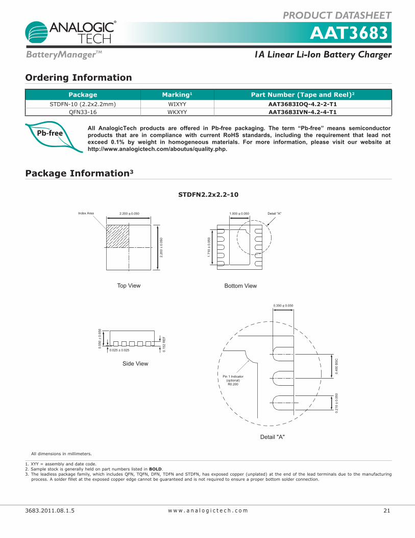
Ordering Information
Package Marking1 Part Number (Tape and Reel)2
STDFN-10 (2.2x2.2mm) WIXYY AAT3683IOQ-4.2-2-T1QFN33-16 WKXYY AAT3683IVN-4.2-4-T1
All AnalogicTech products are offered in Pb-free packaging. The term “Pb-free” means semiconductor products that are in compliance with current RoHS standards, including the requirement that lead not exceed 0.1% by weight in homogeneous materials. For more information, please visit our website at http://www.analogictech.com/aboutus/quality.php.
Package Information3
STDFN2.2x2.2-10
Top View Bottom View
2.20
0 ±
0.05
0
1.71
0 ±
0.05
02.200 ± 0.050 1.000 ± 0.050Index Area
0.025 ± 0.025
0.55
0 ±
0.05
0
0.15
2 R
EF
Side View
Pin 1 Indicator(optional)R0.200
0.40
0 B
SC
0.21
0 ±
0.05
0
0.350 ± 0.050
Detail "A"
Detail "A"
All dimensions in millimeters.
1. XYY = assembly and date code.2. Sample stock is generally held on part numbers listed in BOLD.3. The leadless package family, which includes QFN, TQFN, DFN, TDFN and STDFN, has exposed copper (unplated) at the end of the lead terminals due to the manufacturing process.Asolderfilletattheexposedcopperedgecannotbeguaranteedandisnotrequiredtoensureaproperbottomsolderconnection.

AAT36831A Linear Li-Ion Battery ChargerBatteryManagerTM
PRODUCT DATASHEET
22 3683.2011.08.1.5w w w . a n a l o g i c t e c h . c o m
AAT36831A Linear Li-Ion Battery ChargerBatteryManagerTM
PRODUCT DATASHEET
22 3683.2011.08.1.5w w w . a n a l o g i c t e c h . c o m
Advanced Analogic Technologies, Inc.3230 Scott Boulevard, Santa Clara, CA 95054Phone (408) 737-4600Fax (408) 737-4611
© Advanced Analogic Technologies, Inc.AnalogicTech cannot assume responsibility for use of any circuitry other than circuitry entirely embodied in an AnalogicTech product. No circuit patent licenses, copyrights, mask work rights, or other intellectual property rights are implied. AnalogicTech reserves the right to make changes to their products or specifications or to discontinue any product or service without notice. Except as provided in AnalogicTech’s terms and conditions of sale, AnalogicTech assumes no liability whatsoever, and AnalogicTech disclaims any express or implied warranty relating to the sale and/or use of AnalogicTech products including liability or warranties relating to fitness for a particular purpose, merchantability, or infringement of any patent, copyright or other intellectual property right. In order to minimize risks associated with the customer’s applications, adequate design and operating safeguards must be provided by the customer to minimize inherent or procedural hazards. Testing and other quality control techniques are utilized to the extent AnalogicTech deems necessary to support this warranty. Specific testing of all parameters of each device is not necessarily performed. AnalogicTech and the AnalogicTech logo are trademarks of Advanced Analogic Technologies Incorporated. All other brand and product names appearing in this document are registered trademarks or trademarks of their respective holders.
QFN33-16
3.00
0 ±
0.05
0
Pin 1 Dot By Marking
1.25
0 ±
0.05
0
0.40
0 ±
0.10
0
1.250 ± 0.0503.000 ± 0.050
0.50
0 ±
0.05
0
0.90
0 ±
0.10
0
Pin 1 Identification
C0.3
0.02
5 ±
0.02
5
0.214 ± 0.036
0.230 ± 0.050
Top View Bottom View
Side View
1
13
5
9
All dimensions in millimeters.