A9 SPOT SATELLITE FAMILY: PAST, PRESENT AND … · SPOT SATELLITE FAMILY: PAST, PRESENT AND FUTURE...
6
A9 SPOT SATELLITE FAMILY: PAST, PRESENT AND FUTURE OF THE NS IN SSIQN- - -_ c CE Mr PACHOLCZYK Philippe Centre National d'Etudes Spatiales, 18 Avenue Edouard Belin 31055 Toulouse Cedex, France SUMMaRY SPOT sun-synchronousremote sensing satellites are operated by CNES since February 1986. Today, the SPOT mission and control center (CCM) operates SPOT1, SPOT2 and is ready to operate SPOT3. During these seven years, the way to operate changed and the CCM, initially designed for the control of one satellite, has been modified and upgraded to support these new operating modes. All these events have shown the performances and the limits of the system. A new generation of satellite (SPOT4) will continue the remote sensing mission during the second half of the 90's. Its design takes into account the experience of the first generation and supports several improvements. A new generation of control center (CMP) has been developped and improves the efficiency, quality and reliability of the operations. The CMP is designed for operating two satellites at the same time during launching, in-orbit testing and operating phases. It supports several automatic procedures and improves data retrieval and reporting. Keywords: SPOT, remote sensing systems, mission and control center, satellite operations, operating organization 1. SPOT SATELLITE MISSION The decision of SPOT earth remote sensing program was taken by the French government in 1978. Designed by CMES (Centre National des Etudes Spatiales) and built by France with Belgium and Sweden cooperation, the SPOT system is operational since 1986. It is composed of an image receiving and processing ground segment, a mission and control ground segment and the Spotimagecommercial company, which is in charge of earth images selling. 1.1 Primary Mission The aim of SPOT satellites is to perform images of the whole earth. Equiped by two optical instruments and two magnetic recorders, the satellites can transmit two images of 10 or 20 meters resolution at the same time, in four visible wave bands for SPOT1, SPOT2, SPOT3 and an additional infrared wave band for SPOT4. Each image requests a 25 Mbits per second data link. These images can be recorded on board for further transmissionor directly transmitted down to ground by using a X band (8 GHz) downlink. The SPOT satellites orbit has been precisely defined to insure the mission requirements: - it is a polar orbit lightly inclined with regard of the pole axis. This feature enables, with the earth rotation, the whole earlh observation. - the orbit phase is 26 days long and enables a repetitive image taking. As a matter of fact the side angle viewing capability offers stereoscopicimages capability and a 5 days long accessibility delay. - the orbit is roughtly circular (830 kms) and the images have the same characteristicswhatever the observed point is. - the orbit is sun-synchronous and implies the overflight of the same point at the same date (10302). Then, the images have the same lighting conditions. These orbit characteristics imply a ground segment rhythm with two visibility groups, one in the morning (about 10302) and the other in the evening (about 22302). 1.2 Secondary Missions Since the beginning, SPOT satellites include several passengers which perform secondary missions: DORIS is a doppler measurement instrument used to determine the satellite orbit with a 10 cm accuracy. DORIS is board on SPOT2, SPOT3 and SPOT4 satellites and has its own control center. VEGA is a radar responder instrument running independently of the satellite and providing an accurate radar calibration. VEGA is board on SPOTI, SPOT2, SPOT3 and SPOT4. POAM is a polar ozone atmospheric measurement system which performs a spectral analysis of the polar stratosphericclouds. POAM has its own telemetry link and is monitored by the Consolidated Space Test Center in Sunnyvale, CA. POAM is board on SPOT3. SPOT4 satellite includes some other experiments: VEGETATION is a remote sensing passenger which can provide 1 km accuracy images used for vegetation monitoring. PASTEC is a set of seven experiments related to thermal coating degradation, cosmic radiations effects, satellite dynamic characteristicsduring launch and in- 81 https://ntrs.nasa.gov/search.jsp?R=19940019373 2018-07-11T22:50:47+00:00Z
-
Upload
truongkiet -
Category
Documents
-
view
217 -
download
0
Transcript of A9 SPOT SATELLITE FAMILY: PAST, PRESENT AND … · SPOT SATELLITE FAMILY: PAST, PRESENT AND FUTURE...

A9 SPOT SATELLITE FAMILY: PAST, PRESENT AND
FUTURE OF THE NS IN SSIQN- - - _
c CE Mr PACHOLCZYK Philippe
Centre National d'Etudes Spatiales, 18 Avenue Edouard Belin 3 1055 Toulouse Cedex, France
SUMMaRY SPOT sun-synchronous remote sensing satellites are operated by CNES since February 1986. Today, the SPOT mission and control center (CCM) operates SPOT1, SPOT2 and is ready to operate SPOT3.
During these seven years, the way to operate changed and the CCM, initially designed for the control of one satellite, has been modified and upgraded to support these new operating modes. All these events have shown the performances and the limits of the system.
A new generation of satellite (SPOT4) will continue the remote sensing mission during the second half of the 90's. Its design takes into account the experience of the first generation and supports several improvements.
A new generation of control center (CMP) has been developped and improves the efficiency, quality and reliability of the operations. The CMP is designed for operating two satellites at the same time during launching, in-orbit testing and operating phases. It supports several automatic procedures and improves data retrieval and reporting.
Keywords: SPOT, remote sensing systems, mission and control center, satellite operations, operating organization
1. SPOT SATELLITE MISSION
The decision of SPOT earth remote sensing program was taken by the French government in 1978.
Designed by CMES (Centre National des Etudes Spatiales) and built by France with Belgium and Sweden cooperation, the SPOT system is operational since 1986. It is composed of an image receiving and processing ground segment, a mission and control ground segment and the Spotimage commercial company, which is in charge of earth images selling.
1.1 Primary Mission
The aim of SPOT satellites is to perform images of the whole earth. Equiped by two optical instruments and two magnetic recorders, the satellites can transmit two images of 10 or 20 meters resolution at the same time, in four visible wave bands for SPOT1, SPOT2, SPOT3 and an additional infrared wave band for SPOT4. Each image requests a 25 Mbits per second data link. These images can be recorded on board for further
transmission or directly transmitted down to ground by using a X band (8 GHz) downlink.
The SPOT satellites orbit has been precisely defined to insure the mission requirements:
- it is a polar orbit lightly inclined with regard of the pole axis. This feature enables, with the earth rotation, the whole earlh observation.
- the orbit phase is 26 days long and enables a repetitive image taking. As a matter of fact the side angle viewing capability offers stereoscopic images capability and a 5 days long accessibility delay.
- the orbit is roughtly circular (830 kms) and the images have the same characteristics whatever the observed point is. - the orbit is sun-synchronous and implies the overflight of the same point at the same date (10302). Then, the images have the same lighting conditions.
These orbit characteristics imply a ground segment rhythm with two visibility groups, one in the morning (about 10302) and the other in the evening (about 22302).
1.2 Secondary Missions
Since the beginning, SPOT satellites include several passengers which perform secondary missions:
DORIS is a doppler measurement instrument used to determine the satellite orbit with a 10 cm accuracy. DORIS is board on SPOT2, SPOT3 and SPOT4 satellites and has its own control center.
VEGA is a radar responder instrument running independently of the satellite and providing an accurate radar calibration. VEGA is board on SPOTI, SPOT2, SPOT3 and SPOT4.
POAM is a polar ozone atmospheric measurement system which performs a spectral analysis of the polar stratospheric clouds. POAM has its own telemetry link and is monitored by the Consolidated Space Test Center in Sunnyvale, CA. POAM is board on SPOT3.
SPOT4 satellite includes some other experiments:
VEGETATION is a remote sensing passenger which can provide 1 km accuracy images used for vegetation monitoring.
PASTEC is a set of seven experiments related to thermal coating degradation, cosmic radiations effects, satellite dynamic characteristics during launch and in-
81
https://ntrs.nasa.gov/search.jsp?R=19940019373 2018-07-11T22:50:47+00:00Z
orbit phases and electrostatic charge measurement.
PASTEL is laser &tali& eqeriment and ESBT is a wide waveband transmitter espriment. They will use a geostationnary data relay satellite for payload telemetry link.
Telemet ry \comnds ~ ~ ~ ~ : . l o c a l i z a t i o measures
TTC stations oir,dct s t a t i o n s Images Receiving Stat ions
Images Processing Mission and Contro!, Center
Passengers Spotim. Control Centers Company
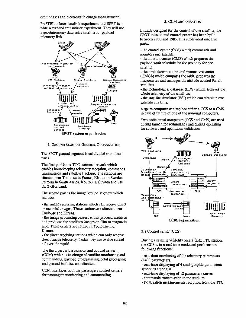
SPOT system Organization
2. GROUND SEGMENT GENERAL ORGANIZATION
The SPOT ground segment is subdivided into three Parts. The first part is the TTC stations network which enables housekeeping telemetry reception, commands transmission and satellite tracking. The stations are situated near Toulouse in France, Kiruna in Sweden, Pretoria in South Africa. Kourou in Guyana and use the 2 GHz band.
The second part is the image ground segment which includes:
- the image receiving stations which can receive direct or recorded images. These stations are situated near Toulouse and Kiruna. - the image processing centers which process, archives and produces the satellites images on film or magnetic tape. These centers are settled in Toulouse and Kiruna. - the direct receiving stations which can only receive direct image telemetry. Today they are twelve spread all over the world.
The third part is the mission and control center (CCM) which is in charge of satellite monitoring and commanding, payload programming, orbit processing and ground facilities coordination.
CCM interfaces with the passengers control centers for passengers monitoring and commanding.
3. CCM ORGANIZATION
Initially designed for the control of one satellite, the SPOT mission and control center has been built between 1980 and 1985. It is subdivided into five parts:
- the control center (CCS) which commands and monitors one satellite. - the mission center (CMS) which prepares the payload work schedule for the next day for one satellite. - the orbit determination and manoeuvre center (OMGS) which computes the orbit, prepares the manoeuvres and manages the attitude control for all satellites. - the technological database (BDS) which archives the whole telemetry of the satellites. - the satellite simulator @SI) which can simulate one satellite at a time.
A spare computer can replace either a CCS or a CMS in case of failure of one of the nominal computers.
Two additionnal computers (CCS and CMS) are used during launch for redundancy and during operating for software and operations validation.
TTC Stations Direct Stations
1
S
datas
a r c h
Spotimage Company
U BDT OMGS
CCM organization
3.1 Control center (CCS)
During a satellite visibility on a 2 GHz TTC station, the CCS is in a real-time mode and performs the following functions:
- real-time monitoring of the telemetry parameters (1400 parameters). - real-time displaying of 4 semi-graphic parameters synoptics among 40. - real-time displaying of 12 parameters cuves. - commands transmission to the satellite. - localization measurements reception from the 'M'C
82

station.
Between two visibilities, the CCS is in a postponed mode and performs the following functions: - preparing the commands plan for the next visibility. - postponed monitoring of the satellite telemetry: on- board configuration, thermal and power monitoring, trend analysis, etc.
The CCS can also play back the telemetry in case of precise investigation.
The CCS interfaces with passengers control centers for passengers housekeeping telemetry providing and passengers commands transmission.
The software management uses alphanumeric displays;
A CCS can manage one satellite and is built on a SOLAR 16-75 computer.
3.2 Mission center (CMS)
The CMS daily performs automatically the payload work schedule to be send to the CCS by taking into account the requests of the following users.
The first user is Spot Image company which sends the earth parts to be shot requested by the end users. The images situated into a 2500 kms circle around Taulouse or Kiruna are directly taken during a pass, the others are recorded on board for further transmission.
The second users are the direct receiving stations which are spread all over the world. They can book visibilities on their station and send direct image requests until 12 hours before executing.
The third user is the CCM engineers team which can program technological operations on the payload.
Above a latitude of 72 degree, a graphic interface with a map background is used for image programming.
The CMS has also a network node role for exchange between CCS and OMGS.
The software management uses alphanumeric displays.
A CMS can manage one satellite and is built on a SOLAR 16-75 computer.
3.3 Orbit determination and manoeuvre center (OMGS)
The OMGS center calculates twice a day a precise satellite orbit by using the localization measurements, after the morning and evening group of visibilities.
It determines a predicting orbit which is used for the payload programming, the TTC visibilities prediction and the management of on-board attitude events (moon or sun sensors. in orbit position, ...).
It also calculates the connection between on board and UT time.
It calculates and generates the co for a manoewre, in order to insure a right orbit.
It uses graphic displays for orbit evolution m e s . The software management uses alphanumeric displays.
The OMGS center can manage the three satellites and run on a CDC 830 computer.
3.4 Technological database (BDT)
All the data related to the GCM and satellite status are daily archived in the technological database: telemetry, sent commands, orbit parameters, ... These data can be retrieved and reported on display, paper or plotter.
Today, the BDT manages more than 20 Gigabytes which represents all the status data of CCM and SPOT satellites since their launch.
The software management uses alphanumeric displays.
The BDT can manage the three satellites and run on a CDC 990 computer.
3.5 Satellite simulator @SI)
The satellite simulator includes a real on-board computer which runs the satellites on-board software. The other equipments and the environment are simulated.
The BSI is used for operations and on-board software releases qualifications.
The BSI can simulate only one satellite at a time and runs on two SOLAR 16-75.
3.6 Human organization
The human organization is subdivided into several parts:
- the center chief with a secretary
- the satellite management service (CB) which is responsible for satellites control and operations, simulator management (9 people).
- the ground technical support service (STS) which is responsible for ground hardware and software management (1 1 people).
- the operational support service (OPS) which is responsible for ground facilities operation and includes controllers (30 people).
One CB, CCS, CMS and OMGS engineer is always available in case of ground or on-board anomaly.
83
3 .Y Software and documentation
CCM soffware has been developped in Fortran and contains more then 1.3 millions of code lines.
In addition of development documentation, uses flight plan and ground operations plan documents. These documents describe all the operating phases (launch, in-orbit test and operating), represent more than 4,000 pages and have been produced with word processing software.
4. CCM SUCCESSIVE ORGANIZATIONS
During these seven years of operation, the CCM organization has been changing several times with respect to the great events of SPOT system.
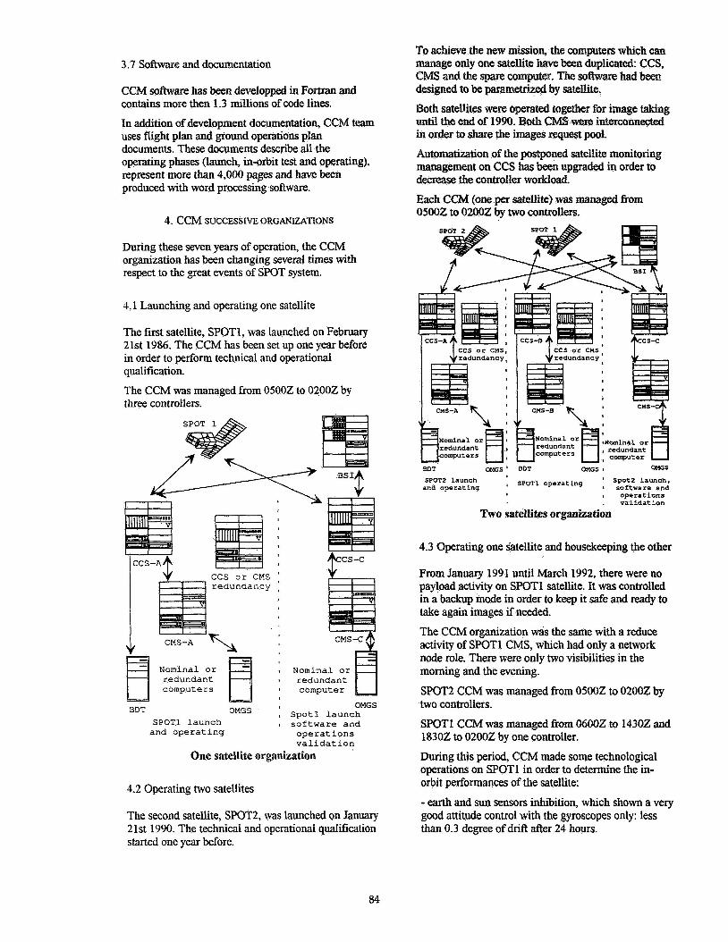
4.1 Launching and operating one satellite
The first satellite, SPOT1, was launched on February 21st 1986. The CCM has been set up one year before in order to perform technical and operational qualification.
The CCM was managed from 05002 to 02002 by three controllers.
Nominal o r I Nominal or r edundan t I r edundan t
I computer
OMGS OMGS 1 S p o t 1 l a u n c h
S P O T l l a u n c h I s o f t w a r e a n d
BDT
a n d o p e r a t i n g o p e r a t i o n s v a l i d a t i o n
One satellite organization
4.2 Operating two satellites
The second satellite, SpOT2, was launched on January 2 1st 1990. The technical and operational qualification started one year before.
designed to be parametrized by satellite.
Both sate&tes were operated together for image taking until the end of 1990. OnneGted in order to share the images request pool.
Automatization of the postponed satellite monitoring management on CCS has been upgraded in order to decrease the controller workload.
Each CCM (one per satellite) was managed from 05002 to 02002 by two controllers.
+CS-c
3 ' F F c
BDT OMGS ' BDT OMGS Q OMGS
SPOT2 launch ' spot2 Launch, and operating ' 1 software and
I operations . validation
Two satellites organization
4.3 Operating one Satellite and housekeeping the other
From January 1991 until March 1992, there were no payload activity on SPOTl satellite. It was controlled in a backup mode in order to keep it safe and ready to take again images if needed.
The CCM organization was the same with a reduce activity of SPOTl CMS, which had only a network node role. There were only two visibilities in the morning and the evening.
SPOT2 CCM was managed from 05002 to 02002 by two controllers.
SPOT1 CCM was managed from 06002 to 14302 and 18302 to 02002 by one controller.
During this period, CCM made some technological operations on SPOTl in order to determine the in- orbit performances of the satellite:
- earth and sun sensors inhibition, which shown a very good attitude control with the gyroscopes only: less than 0.3 degree of drift after 24 hours.
84

- magnetic couplers inhibition, which are used for momentum wheels unsaturation: highlighting of an unforseen wide magnetic moment without impact on attitude control.
- stop of the solar m y spin:, when the solar array is perpendicular and parallel to the of two between the aerodynamic torques. All these operations have shown a great robustness of the satellite attitude control, which is widely inside the requirements, and confirmed'the magnetic and aerodynamic models used.
4.4 Operating one satellite, housekeeping the second and launching the third
SFQT3 will be launched in September 1993 and CCM will be upgraded in order to store SPOT1 and operate SPOT;! during SPOT3 ground qualification and launch. SPOT1 mission will stop at the beginning of November 1993. The modified on-board s o m e will insure attitude control of the satellite without p u n d corrections. Satellite status will only be checked during twa vishilities in the morning and the technological database wiU continue to be filled.
BPT QUOS' OHGS ' t s m 3 launch SPM3 Iawch I S ~ Q T ~
and operating ' SWT2 operacing I Qr sQ&fam 4 apeeratlng , and waratmna, valldat ion
Three satellites organization
SPOT2 and SPOT3 CCM will be managed @om 05002 to Q2QOZ by four controllers.
SPQTl CCM will only be managed during the two check visibilities by one af the four controllers.
4.5 Results and conclusions
The C W organization settied by CMES fix SFQT satellites operating is efficient, reliable and flexible. Indeed SpOTl, designed fw 2 years I&tims is always qxn-itionaI and the EM, designed in 80% for one
satellite, is today able to operate 3 satellites.
Finally satellites control has never been interrupted and there were no mission interruption because of ground failure.
5. SPOT4 NEW GENERATION SATELLITE
SPOT4 satellite will be launched between 1S95 and 1998. Because of a larger telemetry (more than 6,000 parameters in the database) and a more flexible on- board software, this new generalion satellite provides better subsystems observing and commanding.
SFQTS satellite is today on study and will continue the remote sensing mission.
5.1 Ground segment organization
TTC stations
Geneera company user
SPOT4 ground segment
SPOT4 ground segment has been designed to support two satellites at a time and is subdivided into three Parts. The first par& is the 2 G& TTC stations network which includes Toulouse, Kim, Kourou stations and a new one on Kergueien island.
The second part is the image ground segment which includes: - the same image receiving stations as SPOTI. - the same direct receiviRg stations. - ICinma and Toulouse image archiving centers. As regards ta SPOT1, the image processing centers and the payload programming part of the mission center are settled at the premises of the Spotimage company.
The third pat is the control center (CMP) which is in charge of Satellite munitoring and commanding, orbit prwessing and ground facilities coordination.

is on the way of integration at CNES in Toulouse and its technical qualification will begin in 1994.
5.2 CMP organization
CMP center has been designed for two satellites and is subdivided into four parts (Ref. 1):
- the control center (CCS) which commands and monitors one satellite. - the management center (CGS) which prepares the payload command plan, computes the orbit, prepares the manoeuvres, archives the whole telemetry and interfaces with the passengers control centers. - the video server, used during launch phase, which broadcast up to sixteen telemetry synoptics on graphic displays. - the satellite simulator (SSSO) which can simulate one satellite at a time.
Using of uptodate hardware and software enables hnctionnal improvements which improve operations efficiency, quality and reliability.
Two satellites upgrading shall be simply done by adding some new CCS hardware.
5.2.1 CMP improvements
Controllers or engineers use a window based interface on colour graphic displays for satellite or CMP management.
The daily CMP management can be done either manually or automatically (Ref. 2).
At the beginning of the day, the controller will prepare the CMP day workschedule on the CGS and commands preparing, telemetry monitoring and commands sending during a visibility, postponed telemetry monitoring, telemetry archiving will run automatically. He monitors the CMP activities on a timeline graphic chart and acts only in case of anomaly.
Telemetry and commands database management has been improved by using Oracle database software and interfacing all CMP functions with database e,Utracts.
Technological database estracts can be graphically performed and printed on CGS displays.
Engineers Pc's will be connected by a network to the CGS in order to import technological database extract or configuration files and perform them on Pc's softwares.
5.2.2 Human organization
One controller can manage two satellites at a time and both control and management centers associated.
two controllers.
The human organization will be subdivided into several parts:
- the CMP chief with his assistant and secretary.
- the satellite management team wh for satellite control and operations, simulator management (5 people, 1 always on duty).
- the ground support team which is responsible for ground hardware and software management (4 people, 1 always on duty).
facilities operating and includes controllers (6 - the operations team which is responsible for ground
people).
5.2.3 Documentation
A specific software will provide tools for operation plans preparation.
Flight and ground operation plans will be merged and described at the same time on PRQCEX tool, by using a specific language and by referencing either board or ground actions: used synoptics, sent commands, checked telemetry parameters, ground processing workschedule, operator acting.
Operation plans coherence with the data existing on the CMP is automatically checked before printing. PROCEX can also simulate procedure execution and check dynamical coherence.
PRQCEX tool will improve efficiency and reliability of the satellite operations.
5. CONCLUSION
Today, with the CCM, CNES has a 7 year experience on SPOT remote sensing satellites operating and will operate 3 satellites at the same time during 1993.
This experience has been used for the design of the future remote sensing programs and CNES prepares the CMP, a new generation operating center, which will improve efficiency, quality and reliability of the operations.
6. REFERENCES
1. Zaouche, G. 1992. SPOT4 operational control center. In SpaceQps 92.
2. Fratter, I. 1992. Agenda: a task organizer and scheduler. In SpaceOps 92.
The CMP will be managed from 06002 to 22002 by
86