SERVICE MANUAL - Vending Machines, Refurbished and used, Vending
A7-SAR1A6-SAR1
AppendixAppendix
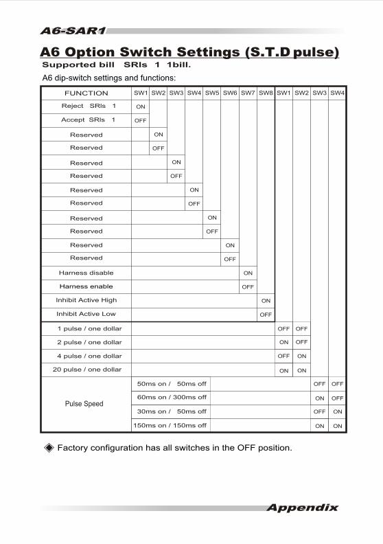
Supported bill SRls 1 1bill.
A6 dip-switch settings and functions:
Factory configuration has all switches in the OFF position.
SW2
OFF
OFF
OFF
OFF
ONOFF
SW6 SW8 SW1 SW2 SW3 SW4SW7
ON
ON
ON
ON
ON
ONON
OFF OFF
OFFON
ONON
SW1
OFF
OFF
OFF
OFF
OFF
SW3 SW4 SW5
ON
ON
ON
ON
ONReserved
Reserved
Reserved
Reserved
Reserved
Reserved
Reserved
Reserved
Reserved
Reserved
FUNCTION
Harness disable
Harness enable
2 pulse / one dollar
20 pulse / one dollar
50ms on / 50ms off
60ms on / 300ms off
30ms on / 50ms off
150ms on / 150ms off
Pulse Speed
Inhibit Active Low
1 pulse / one dollar
4 pulse / one dollar
Inhibit Active High
OFF OFF
OFF
Reject SRls 1
Accept SRls 1
A6 Option Switch Settings (S.T.D pulse)

Telepoint Vending Solutions Middle East & Gulf Distributor
www.tvsarabia.com
Telepoint Vending Solutions - Saudi Arabia - Jeddah - P.O.BOX 13250 - 21491
Fax: (9662) 653 0070
Email: [email protected]

Part Number SW0SA110
Version 1.0

4 - Way AcceptanceLow MaintenanceEasy InstallationRe - Programmable Flash ROM Auto Self -Adjusting Sensor System
Bill Validator
Bill Validator
A6/V6 Series Installation Guide
International Currency Technologies 43010 Osgood Rd. Fremont, CA 94539
Tel (510) 353-0289
Fax (510) 353-0399
E-mail [email protected]
Website www.ict-america.com
Part Number H4458D
Version 5.0

A6 / V6 Bi ll Validator Specifications ..................................... 2
LED Display ...... ............. ..................................................... 4
LED Status ...... ..................................................................... 4
A6 Pin-out Assignments (S.T.D Pulse for 12 V DC) .............. 5
A6 Pin-out Assignments (S.T.D Pulse for 117 V AC) ............. 6
A6 Pin-out Assignments (Multipuls for 117 V AC) ................ 7
V6 Pin-out Assignments (M.D.B. System for 34V DC) ......... 10
Cable .................................................................................... 11
Switch Settings .........................................................(Appendix)
ContentsContents

A6/V6 Bill Validator Specifications
Acceptance Rate
Bill insertion
Acceptance Speed
Interfaces
Bill box Capacity
Power Sources
Weight
Environment Range
96% or greater
4-way Acceptance
Approx. 3 seconds (including bill stacking)
S.T. D. PulseM.D.B. (Multi-Drop Bus)Multipulse
Approx. 300 bills (200~300) 500 bills (300~500) 800 bills (750~850)
34V DC 1.5Amp ( M.D.B) 12V DC 3 Amp 117V AC 0.2Amp (60HZ) 24V AC 1.5Amp (60HZ)
Power Consumption
Max 50 watts
Approx. 2kg (shipping)
Operating Temperature -15 C~60 C
Storage Temperature -30 C~70 C
- 2 -
Humidity 30%~85% RH (no condensation)
This guide contains all A6/V6 specs, but the actual machine matches only one of the specs.
- 3 -
94.0(3.70")
23
5.9
(9.2
9")
130.0(5.12") 500bills
10
7.0
(4.2
1")
48
.1(1
.90
")1
3.0
(0.5
1")
12
9.0
(5.0
8")
50.8(2.00")
115
.0(4
.53
")
115.0(4.53") 300bills
50
0 p
cs.
30
0 p
cs.
80
0 p
cs.
190.0(7.48") 800bills
94.0(3.70")
24
5.4
(9.6
6")
130.0(5.12') 500bills
115.0(4.53") 300bills
50
0 p
cs.
30
0 p
cs.
10
7.0
(4.2
1")
48
.1(1
.90
)
13
.0(0
.51
")
13
2.0
(5.2
0")
116
.0(4
.57
")
50.8(2.00")84.0(3.31")
80
0 p
cs.
190.0(7.48") 800bills
A6&V6
Unit : :mm
( ) : in
- 4 -
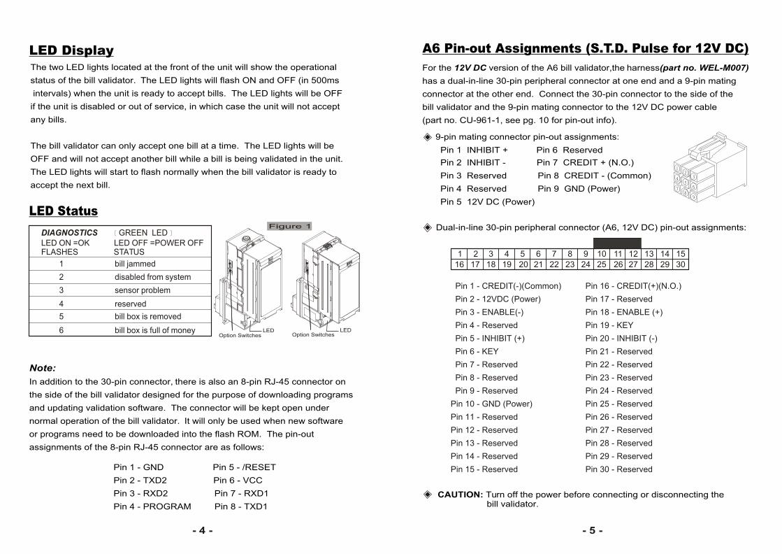
DIAGNOSTICS GREEN LED LED ON =OK LED OFF =POWER OFFFLASHES STATUS
1 bill jammed
2 disabled from system
3 sensor problem
4 reserved
5 bill box is removed
6 bill box is full of money
The two LED lights located at the front of the unit will show the operational
status of the bill validator. The LED lights will flash ON and OFF (in 500ms
intervals) when the unit is ready to accept bills. The LED lights will be OFF
if the unit is disabled or out of service, in which case the unit will not accept
any bills.
The bill validator can only accept one bill at a time. The LED lights will be
OFF and will not accept another bill while a bill is being validated in the unit.
The LED lights will start to flash normally when the bill validator is ready to
accept the next bill.
LED Display
LED Status Figure 1
Option SwitchesLED
Note:
In addition to the 30-pin connector, there is also an 8-pin RJ-45 connector on
the side of the bill validator designed for the purpose of downloading programs
and updating validation software. The connector will be kept open under
normal operation of the bill validator. It will only be used when new software
or programs need to be downloaded into the flash ROM. The pin-out
assignments of the 8-pin RJ-45 connector are as follows:
Pin 1 - GND Pin 5 - /RESET
Pin 2 - TXD2 Pin 6 - VCC
Pin 3 - RXD2 Pin 7 - RXD1
Pin 4 - PROGRAM Pin 8 - TXD1
Option SwitchesLED
- 5 -
A6 Pin-out Assignments (S.T.D. Pulse for 12V DC)
1 2 3 4 5 6 7 8 9 10
2519
11
2620
12
2721
13
282216
14
292317
15
302418
For the 12V DC version of the A6 bill validator,the harness(part no. WEL-M007)
has a dual-in-line 30-pin peripheral connector at one end and a 9-pin mating
connector at the other end. Connect the 30-pin connector to the side of the
bill validator and the 9-pin mating connector to the 12V DC power cable
(part no. CU-961-1, see pg. 10 for pin-out info).
9-pin mating connector pin-out assignments: Pin 1 INHIBIT + Pin 6 Reserved
Pin 2 INHIBIT - Pin 7 CREDIT + (N.O.)
Pin 3 Reserved Pin 8 CREDIT - (Common)
Pin 4 Reserved Pin 9 GND (Power)
Pin 5 12V DC (Power)
Dual-in-line 30-pin peripheral connector (A6, 12V DC) pin-out assignments:
CAUTION: Turn off the power before connecting or disconnecting the bill validator.
Pin 16 - CREDIT(+)(N.O.)
Pin 17 - Reserved
Pin 18 - ENABLE (+)
Pin 19 - KEY
Pin 20 - INHIBIT (-)
Pin 21 - Reserved
Pin 22 - Reserved
Pin 23 - Reserved
Pin 24 - Reserved
Pin 25 - Reserved
Pin 26 - Reserved
Pin 27 - Reserved
Pin 28 - Reserved
Pin 29 - Reserved
Pin 30 - Reserved
Pin 1 - CREDIT(-)(Common)
Pin 2 - 12VDC (Power)
Pin 3 - ENABLE(-)
Pin 4 - Reserved
Pin 5 - INHIBIT (+)
Pin 6 - KEY
Pin 7 - Reserved
Pin 8 - Reserved
Pin 9 - Reserved
Pin 10 - GND (Power)
Pin 11 - Reserved
Pin 12 - Reserved
Pin 13 - Reserved
Pin 14 - Reserved
Pin 15 - Reserved

- 6 -
For the 117V AC version of the A6 bill validator, connect the 30-pin peripheral
connector on one end of the harness (part no. WEL-M008) to the side of the
unit and the 9-pin mating connector to the 117V AC power cable (WEL-M012,
see pg. 12 for pin-out info).
9-pin mating connector pin-out assignments:
Pin 1 NEUTRAL INHIBIT
Pin 2 NEUTRAL ENABLE
Pin 3 HOT ENABLE
Pin 4 117VAC HOT (Power)
Pin 5 Earth - Ground
Pin 6 117VAC NEUTRAL(Power)
Pin 7 CREDIT RELAY (N.O.)
Pin 8 CREDIT RELAY (Common)
Pin 9 Reserved
IMPORTANT: On 117V AC units, the Earth Ground must be located inside the machine.
Dual-in-line 30-pin peripheral connector (A6, 117V AC) pin-out assignments:
1 2 3 4 5 6 7 8 9 10
2519
11
2620
12
2721
13
282216
14
292317
15
302418
12
3
65
4
78
9
A6 Pin-out Assignments (S.T.D Pulse for 117V AC)
CAUTION: Turn off the power before connecting or disconnecting the bill validator.
Pin 16 - CREDIT RELAY(N.O.)
Pin 17 - Reserved
Pin 18 - HOT ENABLE
Pin 19 - KEY
Pin 20 - 117VAC HOT(Power)
Pin 21 - EARTH GROUND
Pin 22 - Reserved
Pin 23 - Reserved
Pin 24 - Reserved
Pin 25 - Reserved
Pin 26 - Reserved
Pin 27 - Reserved
Pin 28 - Reserved
Pin 29 - Reserved
Pin 30 - Reserved
Pin 1 - CREDIT_ RELAY(COM)
Pin 2 - Reserved
Pin 3 - NEUTRAL ENABLE
Pin 4 - 117VAC NEUTRAL(Power)
Pin 5 - NEUTRAL INHIBIT
Pin 6 - KEY
Pin 7 - Reserved
Pin 8 - Reserved
Pin 9 - Reserved
Pin 10 - Reserved
Pin 11 - Reserved
Pin 12 - Reserved
Pin 13 - Reserved
Pin 14 - Reserved
Pin 15 - Reserved
- 7 -
9-pin mating connector pin-out assignments:
Pin 1 Reserved
Pin 2 Reserved
Pin 3 Reserved
Pin 4 117VAC HOT (Power)
Pin 5 Reserved
Pin 6 117VAC NEUTRAL(Power)
Pin 7 CREDIT RELAY (N.O.)
Pin 8 CREDIT RELAY (Common)
Pin 9 Reserved
12
3
65
4
78
9
Dual-in-line 30-pin peripheral connector (A6, 117V AC) pin-out assignments:
1 2 3 4 5 6 7 8 9 10
2519
11
2620
12
2721
13
282216
14
292317
15
302418
NOT USED. NOT USED.
CAUTION: Turn off the power before connecting or disconnecting the bill validator.
18 PIN Connector : Protocol Interface .
9 PIN Connector : Power for AC 117V + 5% .
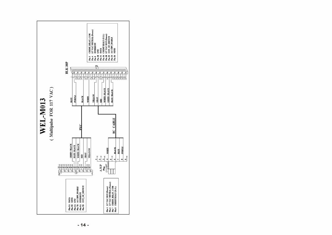
A6 Pin-out Assignments (Multipulse for 117V AC)
Pin 16 - CREDIT REALY (N.O.)
Pin 17 - Reserved
Pin 18 - HOT ENABLE
Pin 19 - KEY
Pin 20 - 117 VAC HOT (Power )
Pin 21 - EARTH GROUND
Pin 22 - /OUT_OF_SERVICE
Pin 23 - Reserved
Pin 24 - /ACCEPT_ENABLE
Pin 25 - /$2_CREDIT
Pin 26 - /SEND
Pin 27 - $1_ENABLE_LOW
Pin 28 - $2_ENABLE_LOW
Pin 29 - $5_ENABLE_LOW
Pin 30 - ESCROW_LOW
Pin 1 - CREDIT_RELAY_COM
Pin 2 - +12V
Pin 3 - NEUTRAL ENABLE
Pin 4 - 117 VAC NEUTRAL(Power)
Pin 5 - NEUTRAL INHIBIT
Pin 6 - KEY
Pin 7 - /$1_CREDIT
Pin 8 - /INTERRUPT
Pin 9 - /$5_CREDIT
Pin 10 - GND
Pin 11 - /DATA
Pin 12 - ESCROW_HIGH
Pin 13 - $5_ENABLE_HIGH
Pin 14 - $2_ENABLE_HIGH
Pin 15 - $1_ENABLE_HIGH

- 8 - - 9 -
DATA TRANSMISSION TIMING
SERIAL INTERFACE STATUS MASSAGE
SINGLE MESSAGE TRANSMISSION
/ACCEPT ENABLE
/INTERRUPT
/SEND
/DATA
MSB 7 6 5 4 3 2 1 0 LSB
"1" RESVRVED CODES STATUS BILL VALUE HEX CODE
$ 1 CREDIT 1 0 0 0 0 0 0 1 81
1 0 0 0 0 0 1 0 82
1 0 0 0 0 0 1 1 83
1 0 0 0 0 1 0 0 84
1 0 0 0 0 1 0 1 85
1 0 0 0 0 1 1 0 86
1 0 0 0 0 1 1 1 87
1 0 0 0 1 0 0 1 89
1 0 0 0 1 0 1 0 8A
1 0 0 0 1 0 1 1 8B
1 0 0 0 1 1 0 0 8C
1 0 0 0 1 1 0 1 8D
RESERVED
$ 5 CREDIT
$ 10 CREDIT
RESERVED
$ 50 CREDIT
RESERVED
VEND
RESERVED
SLUG
FAILURE
STACKER FULL/
STACKERLESS JAM
RETURN
5 MS+.5 MS/-0
1 SEC . MAX
150 MS TYP
2 MS MAX.
5 MS MAX.
5 MS +/- .5 MS
2 MS MIN.
NO MAX. LIMIT
600 BAUD
A A
0 MS MIN.
CREDIT
VEND/RETURN CREDIT
0
1
1
0 1 2 3 4 5 6 7
BIT
*1
SERIAL INTERFACE
INTERFACE CONNECTOR :
Pin 1
/ $ 5 CRETID
/ $ 1 CRETID
/$ 2 CRETID Pin
Pin 1
Control Bd. Cover
Pin 10
Pin 9
Pin 18
Key / Latch
13
Pin 14 /SEND Pin 15 $ 1 ENABLE , Low
Pin 16 $ 2 ENABLE , Low
Pin 17 $ 5 ENABLE , Low Pin 18 ESCROW , Low
Pin 2 INTERRUPT
Pin 3
Pin 4 GROUND
Pin 5 /DATA
Pin 6 ESCROW . High .
Pin 7 $ 5 ENABLE , High
Pin 8 $ 2 ENABLE , High
Pin 9 $ 1 ENABLE , High
Pin 10 /OUT-OF-SERVICE
Pin 11 /DEBUG DATA
Pin 12 /ACCEPT ENABLE
CONNECTOR
PIN LOCATIONS
18-pin mating connector pin-out assignments:
- 11 -
Ca
ble
- 10 -
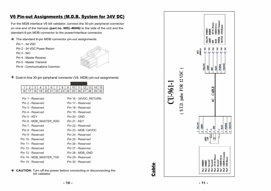
For the MDB interface V6 bill validator, connect the 30-pin peripheral connector
on one end of the harness (part no. WEL-M006) to the side of the unit and the
standard 6-pin MDB connector to the power/interface connector.
The standard 6-pin MDB connector pin-out assignments:
Pin 1 - 34 VDC
Pin 2 - 34 VDC Power Return
Pin 3 - N/C
Pin 4 - Master Receive
Pin 5 - Master Transmit
Pin 6 - Communications Common
Dual-in-line 30-pin peripheral connector (V6, MDB) pin-out assignments:
V6 Pin-out Assignments (M.D.B. System for 34V DC)
1 2 3 4 5 6 7 8 9 10
2519
11
2620
12
2721
13
282216
14
292317
15
302418
45
6
32
1
CAUTION: Turn off the power before connecting or disconnecting the bill validator.
Pin 16 - 34VDC_RETURN
Pin 17 - Reserved
Pin 18 - Reserved
Pin 19 - Reserved
Pin 20 - GND
Pin 21 - KEY
Pin 22 - Reserved
Pin 23 - MDB +34VDC
Pin 24 - Reserved
Pin 25 - Reserved
Pin 26 - Reserved
Pin 27 - Reserved
Pin 28 - MDB_GND
Pin 29 - Reserved
Pin 30 - Reserved
Pin 1 - Reserved
Pin 2 - Reserved.
Pin 3 - Reserved
Pin 4 - Reserved
Pin 5 - KEY
Pin 6 - MDB_MASTER_RXD
Pin 7 - Reserved
Pin 8 - Reserved
Pin 9 - Reserved
Pin 10 - Reserved
Pin 11 - Reserved
Pin 12 - Reserved
Pin 13 - Reserved
Pin 14 - MDB_MASTER_TXD
Pin 15 - Reserved

- 12 -
(Op
tion
)
- 13 -
- 14 -