A300-600 Center Wing Box Ultrasonic...
17
A300-600 Center Wing Box Ultrasonic Inspection Presented by: Carl Fisher & John Silvis Supporting Team: Stephen Cavaleri Loi Nguyen John Ellington, senior manager
Transcript of A300-600 Center Wing Box Ultrasonic...

A300-600
Center Wing Box
Ultrasonic Inspection
Presented by:
Carl Fisher & John Silvis
Supporting Team:
Stephen Cavaleri
Loi Nguyen
John Ellington, senior manager

2
History
Fastener holes of center wing box (CWB) lower skin
Ref. A300-600 Non-Destructive Testing Manual 57-10-45, Procedures A, B, C
• Airworthiness Directive (AD) driven inspection
• Original inspections began in 2006 with eddy current rotor bolt hole
− Cracks were addressed per Airbus procedure
− Required follow-up inspections conducted with ultrasonic testing (UT)
• Written procedures made no mention of removing sealant or paint, nor
mentioned adjusting the gain during inspection
− Wheel well area is susceptible to fuel and hydraulic leaks, which resulted in
excess sealant and peeled/bulging paint in the inspection area
− Non-routines were written to clean area
− Findings resulted in inspections being elevated to FedEx & Airbus
Engineering for repair procedures
DIAGRAMS FOR REFERENCE ONLY
A300-600 Non-Destructive Testing Manual 57-10-45, Procedures A, B, C

3
Inspection Area
AFT
Lower Wing
Fuselage
Wheel Well Door

4
Adjustment of Equipment on Reference Block
Ultrasonic Equipment Settings
Frequency : 10MHz
Range : 140 mm (5.512 in.)
Delay : 0.000.s/s
MLT Velocity : 3240 m/s (0.126 in./.s)
Rectification Mode : Fullwave
DIAGRAMS FOR REFERENCE ONLY
A300-600 Non-Destructive Testing Manual 57-10-45, Procedures A, B, C

5
Instrument Calibration
• Procedure C Table
− Standard hole echo with slot echo/EDM notch
− Range setting with location of slot echo on base line
HOLE TYPE TO
BE INSPECTED
HOLE ECHO
“a”
SLOT
ECHO “b”
REFERENCE
HOLE
SEARCH
UNIT
1 4.5 5.0 D CEP24
2 4.8 5.2 A CEP20
3 6.8 7.5 D CEP23
4 5.5 6.0 E CEP24
5 6.2 6.4 B CEP23
DIAGRAMS FOR REFERENCE ONLY
A300-600 Non-Destructive Testing Manual 57-10-45, Procedures A, B, C

6
Preparation for Inspection – Procedure A Steps
A. Make sure that the surface to be inspected is clean and
smooth
B. Check the inspection area for any visible damage or
discontinuities
No NTM reference to remove paint
DIAGRAMS FOR REFERENCE ONLY
A300-600 Non-Destructive Testing Manual 57-10-45, Procedures A, B, C

7
Preparation for Inspection – Procedure A
Inspection Areas
(possible crack
locations)
DIAGRAMS FOR REFERENCE ONLY
A300-600 Non-Destructive Testing Manual 57-10-45, Procedures A, B, C
Procedure
“A”
AFT
Fuselage
Wing

8
Preparation for Inspection – Procedure B
Inspection Area
(possible crack
location)
DIAGRAMS FOR REFERENCE ONLY
A300-600 Non-Destructive Testing Manual 57-10-45, Procedures A, B, C
Procedure
“B”
AFT
Fuselage
Wing

9
Preparation for Inspection – Procedure C
Inspection Area
(possible crack
location)
DIAGRAMS FOR REFERENCE ONLY
A300-600 Non-Destructive Testing Manual 57-10-45, Procedures A, B, C
c
Procedure
“C”
AFT
Fuselage
Wing

10
UT Re-Inspection Sealant Challenge Encountered
• Excess sealant around fasteners and seams to repair fuel
leaks
− Transducer not positioned correctly
Sealant that
needs to be
removed
DIAGRAMS FOR REFERENCE ONLY
A300-600 Non-Destructive Testing Manual 57-10-45, Procedures A, B, C
Area that needs paint and sealant removed
AFT

11
Transducer Positioning
Sealant
NOT
removed
Sound path is
NOT aligned
with the hole
DIAGRAMS FOR REFERENCE ONLY
A300-600 Non-Destructive Testing Manual 57-10-45, Procedures A, B, C
Sound path is
aligned with
the hole
Sealant has
been removed

12
UT Re-Inspection Paint Challenge Encountered
• Spray paint not allowed, roll or brush application only
DIAGRAMS FOR REFERENCE ONLY
A300-600 Non-Destructive Testing Manual 57-10-45, Procedures A, B, C

13
2011 revision
Preparation for Inspection – Procedure B & C
A. Make sure that the surface
to be inspected is clean and
smooth
B. Check the inspection area
for any visible damage or
discontinuities
No NTM reference to remove paint
2016 revision
A. Check paint condition in
inspection area and
remove it if necessary
B. Check sealant condition on the
edge to the splice. If the
sealant prevents getting to
hole echo, then remove
sealant
C. Make sure that the surface to
be inspected is clean and
smooth
D. Check the inspection area for
any visible damage or
discontinuitiesDIAGRAMS FOR REFERENCE ONLY
A300-600 Non-Destructive Testing Manual 57-10-45, Procedures A, B, C
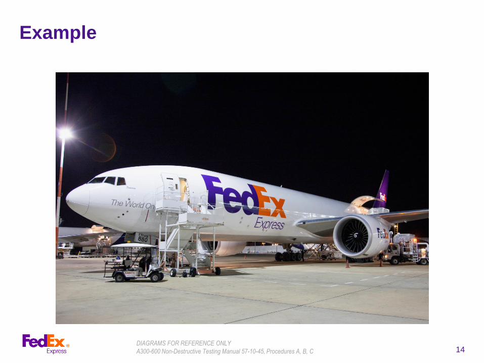
14
Example
DIAGRAMS FOR REFERENCE ONLY
A300-600 Non-Destructive Testing Manual 57-10-45, Procedures A, B, C

15
Procedural Change to On-Aircraft Inspection
Procedure
A. Apply couplant in the area to be inspected.
B. Couple the search unit to the inspection surface in a similar position to
that shown in Figure 415.
C. Adjust the search unit position to get the signal from the bolt hole at
same position than during the calibration step.
D. Do swivel scan at this position.
E. Cracks will be indicated by a change over signal from the bolt hole to
the crack. The bolt hole signal will fall and the crack signal will rise as
the search unit is moved away from the bolt hole position, towards the
crack position.
F. Measure the length of all detected cracks in accordance with Chapter
51-10-07, Page Block 401.
G. Repeat the Steps A thru F for all the inspection areas.
Adjust the gain to get a
100% FSH (full screen height) of the bolt hole.
DIAGRAMS FOR REFERENCE ONLY
A300-600 Non-Destructive Testing Manual 57-10-45, Procedures A, B, C

16
Summary
• Inspection procedures were incomplete
− Procedures taken literally, without applying standard practices, could
result in missed or inaccurate indications
• Challenge all operators to consider reviewing procedures
− Document the tribal knowledge applied every day
− Share best practices
DIAGRAMS FOR REFERENCE ONLY
A300-600 Non-Destructive Testing Manual 57-10-45, Procedures A, B, C

17
Questions?