A.3 Lightning and surge voltage protection -...
15
Appendix A.3 Lightning and surge voltage protection 1 SIEMENS CPU 31xC and CPU 31x: Installation Operating Instructions, 06/2010, A5E00105492-11 A.3 Lightning and surge voltage protection A.3.1 Overview Preface One of the most common causes of failure is overvoltage caused by: ● Atmospheric discharges ● Electrostatic discharges ● Switching overvoltages The concepts or measures for protection from overvoltages is based on the lightning protection zone concept. The rules to be complied with for the transitions between the individual lightning protection zones are presented here. Note This section can only provide you with the general guide on protecting the S7-300 from overvoltage. Complete protection from overvoltage is only guaranteed if the entire system design is based on the lightning protection zone concept. Comprehensive consideration must be given to this when planning construction of facilities. We therefore recommend that you contact your Siemens representative or a company specialized in lightning and overvoltage protection if you require more detailed information about overvoltage. In the following we refer to the overvoltage protection device using the normative terminology, i.e., according to the degree of hazard expected, overvoltage suppressor for pulse shape 8/20 μs and lightning current suppressor for pulse shape 10/350 μs. Further references The following information is based on the lightning protection zone concept described in IEC IEC 62305-4 - "Protection against LEMP". SIEMENS CPU 31xC and CPU 31x: Installation Operating Instructions, 06/2010, A5E00105492-11 SIEMENS
Transcript of A.3 Lightning and surge voltage protection -...

Appendix A.3 Lightning and surge voltage protection
1SIEMENS CPU 31xC and CPU 31x: Installation Operating Instructions, 06/2010, A5E00105492-11
A.3 Lightning and surge voltage protection
A.3.1 Overview
Preface One of the most common causes of failure is overvoltage caused by: ● Atmospheric discharges● Electrostatic discharges● Switching overvoltagesThe concepts or measures for protection from overvoltages is based on the lightning protection zone concept. The rules to be complied with for the transitions between the individual lightning protection zones are presented here.
Note This section can only provide you with the general guide on protecting the S7-300 from overvoltage. Complete protection from overvoltage is only guaranteed if the entire system design is based on the lightning protection zone concept. Comprehensive consideration must be given to this when planning construction of facilities. We therefore recommend that you contact your Siemens representative or a company specialized in lightning and overvoltage protection if you require more detailed information about overvoltage. In the following we refer to the overvoltage protection device using the normative terminology, i.e., according to the degree of hazard expected, overvoltage suppressor for pulse shape 8/20 μs and lightning current suppressor for pulse shape 10/350 μs.
Further references The following information is based on the lightning protection zone concept described in IEC IEC 62305-4 - "Protection against LEMP".
SIEMENS CPU 31xC and CPU 31x: Installation Operating Instructions, 06/2010, A5E00105492-11
SIEMENS

Appendix A.3 Lightning and surge voltage protection
A.3.2 Lightning protection zone concept
Principle of the lightning protection zone concept according to IEC 62305-4, DIN EN 62305-4, VDE 0185-305-4
The principle behind the lightning protection zone concept is the division of the volume to be protected from overvoltages (e.g. a control room) into lightning protection zones based on EMC considerations (see figure A-2). The various lightning protection zones (LPZ: Lightning Protection Zone) are delimited spatially as follows and not necessarily by physical boundaries, such as walls, floors, etc.
Lightning protection zones (LPZ: Lightning Protection Zone) Outside areas of a building with risk of a direct strike Lightning protection zone LPZ 0A Outside areas of a building that are not at risk of a direct strike Lightning protection zone LPZ 0B Inside areas of a building that follow lightning protection zone 0B
Lightning protection zone LPZ 1
Inside areas of a building that normally represent separate EMC-reducing rooms and are in lightning protection zone 1
Lightning protection zone LPZ 2
Electrical equipment (with shielding properties) in lightning protection zone 2
Lightning protection zone LPZ 3
Effects of the Lightning Strike Direct lightning strikes occur in lightning protection zone 0A. Effects of the lightning strike are high-energy lightning currents and strong electromagnetic fields. Effects must be reduced from one lightning protection zone to the next through suitable lightning current or surge arresters/shielding measures.
Overvoltage Electromagnetic fields of the lightning channel can be reduced with appropriate shielding measures. Overvoltages due to inductions can be reduced to an non-dangerous level starting in lightning protection zone 0B using surge arresters.
2SIEMENS CPU 31xC and CPU 31x: Installation Operating Instructions, 06/2010, A5E00105492-11

Appendix A.3 Lightning and surge voltage protection
Diagram of the lightning protection zones The following schematic diagram shows the implementation of the lightning protection zone concept for a building with outside lightning protection.
Figure A-2 Lightning protection zones of a building with outside lightning protection
Principle of interfaces between the lighting protection zones Measures must be taken to reduce the peak current load and the magnetic fields at the interfaces between the lightning protection zones. Each zone-penetrating metallic/electrical system must be incorporated into the equipotential bonding at the zone transition.
Note Metal systems include ducts, structural parts, pipes (water, gas and heat), etc. Electrical systems include power and IT cables and wires (e.g. line voltage, bus cable, ...).
3SIEMENS CPU 31xC and CPU 31x: Installation Operating Instructions, 06/2010, A5E00105492-11

Appendix A.3 Lightning and surge voltage protection
A.3.3 Rules for the interface between the lightning protection zones 0 and 1
Rules for the interface 0A to 1 (lightning protection equipotential bonding) For lightning protection equipotential bonding at the interface of lightning protection zone 0A to 1, the following applies: ● Use of surge arresters prevents introduction of lightning partial currents into buildings.● Creation of a local equipotential bonding at the transition of lightning protection zones,
with incorporation of metal supply systems (pipes, air ducts, cable ducts, cable channelsetc.).
Components for the lightning protection equipotential bonding
Table A- 7 Components for the lightning protection equipotential bonding
Seq. No.
Cables for ... Connection at the interface 0A to 1 with:
Item number
1 3-phase TN-C system DEHNventil® DV M TNC 255 DEHNventil® DV M TNC 255 FM *
951 300 951 305 *
2 3-phase TN-S system DEHNventil® DV M TNS 255 DEHNventil® DV M TNS 255 FM *
951 400 951 405 *
3 3-phase TT system DEHNventil® DV M TT 255 DEHNventil® DV M TT 255 FM *
951 310 951 315 *
4 AC TN-S system DEHNventil® DV M TN 255 DEHNventil® DV M TN 255 FM *
951 200 951 205 *
5 AC TT system DEHNventil® DV M TT 2P 255 DEHNventil® DV M TT 2P 255 FM *
951 110 951 115 *
6 Supply UN = 24 VDC: BLITZDUCTOR® XT, basic unit BXT BAS BLITZDUCTOR® XT, Module BXT ML2 B 180 (IL = 1.2A) (2-wire)
920 300 920 211
7 Supply UN = 24 VDC: DEHNbloc® M, DB M 1 150 DEHNbloc® M, DB M 1 150 FM * (2 ea. required)
961 110 961 115 *
8 MPI bus cable, RS485, RS 232 (V.24)
BLITZDUCTOR® XT, basic unit BXT BAS BLITZDUCTOR® XT, Module BXT ML2 B 180 (2-wire)
920 300 920 211
9 Inputs/outputs of digital modules UN = 24 VDC:
BLITZDUCTOR® XT, basic unit BXT BAS BLITZDUCTOR® XT, Module BXT ML4 B 180 (IL = 1.2A) (4-wire)
920 300 920 310
10 Inputs/outputs of digital modules UN = 230 VAC:
DEHNbloc® M, DB M 1 255 DEHNbloc® M, DB M 1 255 * (2 ea. required)
961 120 961 125 *
4SIEMENS CPU 31xC and CPU 31x: Installation Operating Instructions, 06/2010, A5E00105492-11

Appendix A.3 Lightning and surge voltage protection
Seq. No.
Cables for ... Connection at the interface 0A to 1 with:
Item number
11 Inputs/outputs of analog modules (e.g. 4-20 mA, 1-10V)
BLITZDUCTOR® XT, basic unit BXT BAS BLITZDUCTOR® XT, Module BXT ML4 B 180 (IL = 1.2A) (4-wire)
920 300 920 310
* Version: With remote indication contactComponents of the series BLITZDUCTOR® XT can be remotely monitored with the appropriate accessories. For further information, refer to http://www.dehn.de Direct order of components via: DEHN+SÖHNE GMBH+CO.KG. Hans-Dehn-Str. 1 D-92318 Neumarkt Tel. +49 (0)9181-906-730
Rules for the interface 0B to 1 (strong electromagnetic coupling) For overvoltage protection at the interface of lightning protection zone 0B to 1, the following applies: ● Use of power cables with peak current-capable cable shields (e.g., NYCWY) or twisted-
pair IT cables (for example, A2Y(K)Y).● Laying cables and lines
– In continuous, peak current-capable metal pipes that are grounded at both ends– In reinforced concrete channels in which the reinforcement is grounded at both ends– On closed metal cable racks that are grounded at the beginning and end.
● Use of fiber optic cables without a metal shield if such a transmission is intended.● Creation of a local equipotential bonding at the transition of lightning protection zones,
with incorporation of metal supply systems (pipes, air ducts, cable ducts, cable channelsetc.) and electrical wire and cable systems.
Additional measures If the actions listed above cannot be performed, protection by means of surge arresters must be provided. The following table contains overvoltage suppressors that may be used to protect facilities.
Overvoltage protection of 24 VDC power supply Always use the BLITZDUCTOR VT, type AD 24 V for the 24 VDC power supply module of the S7-300. All other surge arrestors do not meet the tolerance range (20.4 - 28.8 V) of the S7300
General information on use of surge arresters If, taking into account the tolerance range, the voltages that occur in the system exceed the specified maximum limits of the surge arresters used, surge arrestors of the next highest rated voltage series are to be used.
5SIEMENS CPU 31xC and CPU 31x: Installation Operating Instructions, 06/2010, A5E00105492-11

Appendix A.3 Lightning and surge voltage protection
Components for the overvoltage protection
Table A- 8 Components for the overvoltage protection
Seq. No.
Cables for ... Connection at the interface 0B to 1 with:
Item number
1 3-phase TN-C system DEHNguard® DG M TNC 275 DEHNguard® DG M TNC 275 FM *
952 300 952 305 *
2 3-phase TN-S system DEHNguard® DG M TNS 275 DEHNguard® DG M TNS 275 FM *
952 400 952 405 *
3 3-phase TT system DEHNguard® DG M TT 275 DEHNguard® DG M TT 275 FM *
952 310 952 315 *
4 AC TN-S system DEHNguard® DG M TN 275 DEHNguard® DG M TN 275 FM *
952 200 952 205 *
5 AC TT system DEHNguard® DG M TT 2P 275 DEHNguard® DG M TT 2P 275 FM *
952 110 952 115 *
6 Supply UN = 24 VDC: BLITZDUCTOR® VT, BVT AD 24 918 402 7 MPI/DP RS 485 bus cable BLITZDUCTOR® XT, basic unit BXT BAS
BLITZDUCTOR® XT, Module BXT ML2 BD HFS 5 920 300 920 271
8 RS 232 (V.24) bus cable BLITZDUCTOR® XT, basic unit BXT BAS BLITZDUCTOR® XT, Module BXT ML2 BE S 12
920 300 920 222
9 Industrial Ethernet DEHNpatch DPA M CLE RJ45B 48 929 121 10 Inputs of digital modules UN =
24 VDC: DEHNconnect RK, DCO RK ME 24 (IL = 0.5 A)
919 921
11 Outputs of digital modules UN = 24 VDC:
DEHNconnect RK, DCO RK D 5 24 (IL = 10.0 A)
919 986
12 Inputs/outputs of digital modules UN = 230 VAC:
DEHNguard® DG S 275 DEHNguard® DG S 275 FM * N-PE arrester in the TT system DEHNgap C S, DGP C S DEHNgap C S, DGP C S FM *
952 070 952 090 *
952 030 952 035 *
13 Inputs/outputs of analog modules (e.g. 4-20 mA, 1-10 V)
DEHNconnect RK, DCO RK ME 24 (IL = 0.5 A)
919 921
* Version: With remote indication contactComponents of the series BLITZDUCTOR® XT can be remotely monitored with the appropriate accessories. For further information, refer to http://www.dehn.de
6SIEMENS CPU 31xC and CPU 31x: Installation Operating Instructions, 06/2010, A5E00105492-11

Appendix A.3 Lightning and surge voltage protection
A.3.4 Rules for the interface between the lightning protection zones 1 and 2
Rules for the interface 1 to 2 (strong electromagnetic coupling) For overvoltage protection at the interface 1 to 2, the following applies: ● Use of power cables with peak current-capable cable shields (e.g., NYCWY) or twisted-
pair IT cables (for example, A2Y(K)Y). ● Laying cables and lines
– In continuous, peak current-capable metal pipes that are grounded at both ends, or– In reinforced concrete channels in which the reinforcement is grounded at both ends,
or– On closed metal cable racks that are grounded at the beginning and end.
● Use of fiber optic cables without a metal shield if such a transmission is intended.● Creation of a local equipotential bonding at the transition of lightning protection zones,
with incorporation of metal supply systems (pipes, air ducts, cable ducts, cable channelsetc.) and electrical wire and cable systems.
Additional measures If the actions listed above cannot be performed, protection by means of surge arresters must be provided. The following table contains overvoltage suppressors that may be used to protect facilities.
Overvoltage protection of 24 VDC power supply Always use the BLITZDUCTOR VT, type AD 24 V for the 24 VDC power supply module of the S7-300. All other surge arrestors do not meet the tolerance range (20.4 - 28.8 V) of the S7300
General information on use of surge arresters If, taking into account the tolerance range, the voltages that occur in the system exceed the specified maximum limits of the surge arresters used, surge arrestors of the next highest rated voltage series are to be used.
7SIEMENS CPU 31xC and CPU 31x: Installation Operating Instructions, 06/2010, A5E00105492-11

Appendix A.3 Lightning and surge voltage protection
Components for the overvoltage protection
Table A- 9 Components for the overvoltage protection
Seq. No.
Cables for ... Connection at the interface 1 to 2 with:
Item number
1 3-phase TN-C system DEHNguard® DG M TNC 275 DEHNguard® DG M TNC 275 FM *
952 300 952 305 *
2 3-phase TN-S system DEHNguard® DG M TNS 275 DEHNguard® DG M TNS 275 FM *
952 400 952 405 *
3 3-phase TT system DEHNguard® DG M TT 275 DEHNguard® DG M TT 275 FM *
952 310 952 315 *
4 AC TN-S system DEHNguard® DG M TN 275 DEHNguard® DG M TN 275 FM *
952 200 952 205 *
5 AC TT system DEHNguard® DG M TT 2P 275 DEHNguard® DG M TT 2P 275 FM *
952 110 952 115 *
6 Supply UN = 24 VDC: BLITZDUCTOR® VT, BVT AD 24 918 402 7 MPI/DP RS 485 bus cable BLITZDUCTOR® XT, basic unit BXT BAS
BLITZDUCTOR® XT, Module BXT ML2 BD HFS 5 920 300 920 271
8 RS 232 (V.24) bus cable BLITZDUCTOR® XT, basic unit BXT BAS BLITZDUCTOR® XT, Module BXT ML2 BE S 12
920 300 920 222
9 Industrial Ethernet DEHNpatch DPA M CLE RJ45B 48 929 121 10 Inputs of digital modules UN =
24 VDC: DEHNconnect RK, DCO RK ME 24 (IL = 0.5 A)
919 921
11 Outputs of digital modules UN = 24 VDC:
DEHNconnect RK, DCO RK D 5 24 (IL = 10.0 A)
919 986
12 Inputs/outputs of digital modules UN = 230 VAC:
DEHNguard® DG S 275 DEHNguard® DG S 275 FM * N-PE arrester in the TT system DEHNgap DGP C S DEHNgap DGP C S FM *
952 070 952 090 *
952 030 952 035 *
13 Inputs/outputs of analog modules (e.g. 4-20 mA, 1-10 V)
DEHNconnect RK, DCO RK ME 24 (IL = 0.5 A)
919 921
* Version: With remote indication contactComponents of the series BLITZDUCTOR® XT can be remotely monitored with the appropriate accessories. For further information, refer to http://www.dehn.de
8SIEMENS CPU 31xC and CPU 31x: Installation Operating Instructions, 06/2010, A5E00105492-11

Appendix A.3 Lightning and surge voltage protection
A.3.5 Rules for the interface between the lightning protection zones 2 and 3
Rules for the interface 2 to 3 (electromagnetic coupling) For overvoltage protection at the interface 2 to 3, the following applies: ● Use of power cables with peak current-capable cable shields (e.g., NYCWY) or twisted-
pair IT cables (for example, A2Y(K)Y). ● Laying cables and lines
– In continuous, peak current-capable metal pipes that are grounded at both ends, or– In reinforced concrete channels in which the reinforcement is grounded at both ends,
or– On closed metal cable racks that are grounded at the beginning and end.
● Use of fiber optic cables without a metal shield if such a transmission is intended.● Creation of a local equipotential bonding at the transition of lightning protection zones,
with incorporation of metal supply systems (pipes, air ducts, cable ducts, cable channelsetc.) and electrical wire and cable systems.
Additional measures If the actions listed above cannot be performed, protection by means of surge arresters must be provided. The following table contains overvoltage suppressors that may be used to protect facilities.
Overvoltage protection of 24 VDC power supply Always use the BLITZDUCTOR VT, type AD 24 V for the 24 VDC power supply module of the S7-300. All other surge arrestors do not meet the tolerance range (20.4 - 28.8 V) of the S7300
General information on use of surge arresters If, taking into account the tolerance range, the voltages that occur in the system exceed the specified maximum limits of the surge arresters used, surge arrestors of the next highest rated voltage series are to be used.
9SIEMENS CPU 31xC and CPU 31x: Installation Operating Instructions, 06/2010, A5E00105492-11

Appendix A.3 Lightning and surge voltage protection
Components for the overvoltage protection
Table A- 10 Components for the overvoltage protection
Seq. no.
Cables for ... Connection at the interface 2 to 3 with:
Item number
1 3-phase TN-S system, TT system
DEHNrail® DR M 4P 255 DEHNrail® DR M 4P 255 FM * (IL = 25.0 A)
953 400 953 405 *
2 3-phase TN-S system, TT system
DEHNrail® DR M 2P 255 DEHNrail® DR M 2P 255 FM * (IL = 25.0 A)
953 200 953 205 *
3 Supply UN = 24 VDC: BLITZDUCTOR® VT, BVT AD 24 918 402 4 MPI/DP RS 485 bus cable BLITZDUCTOR® XT, basic unit BXT BAS
BLITZDUCTOR® XT, Module BXT ML2 BD HFS 5 920 300 920 271
5 RS 232 (V.24) bus cable BLITZDUCTOR® XT, basic unit BXT BAS BLITZDUCTOR® XT, Module BXT ML2 BE S 12
920 300 920 222
6 Industrial Ethernet DEHNpatch DPA M CLE RJ45B 48 929 121 7 Inputs of digital modules UN =
24 VDC: DEHNconnect RK, DCO RK ME 24 (IL = 0.5 A)
919 921
8 Outputs of digital modules UN = 24 VDC:
DEHNconnect RK, DCO RK D 5 24 (IL = 10.0 A)
919 986
9 Inputs/outputs of digital modules UN = 230 VAC:
DEHNguard® DG S 275 DEHNguard® DG S 275 FM * N-PE arrester in the TT system DEHNgap C S, DGP C S DEHNgap C S, DGP C S FM *
952070 952 090 *
952 030 952 035 *
10 Inputs/outputs of analog modules (e.g. 4-20 mA, 1-10 V)
DEHNconnect RK, DCO RK ME 24 (IL = 0.5 A)
919 921
* Version: With remote indication contactComponents of the series BLITZDUCTOR® XT can be remotely monitored with the appropriate accessories. For further information, refer to http://www.dehn.de
10SIEMENS CPU 31xC and CPU 31x: Installation Operating Instructions, 06/2010, A5E00105492-11

Appendix A.3 Lightning and surge voltage protection
A.3.6 Example: Surge protection circuit for networked S7-300 CPUs The figure shows the required measures for the protection of two networked S7-300 against lightning strikes and overvoltage.
2
1
9
4
3 5 1076 3 5 5 6 7 10
9 9
8
99
9 9
8
4
11SIEMENS CPU 31xC and CPU 31x: Installation Operating Instructions, 06/2010, A5E00105492-11

Appendix A.3 Lightning and surge voltage protection
Components of the application example The following table explains the components of the application example:
Seq. No. Component Meaning
① Combination arrester 230/400 VAC supply, DEHNventil® DV M TNC 255 Part. no. 951 300 DEHNventil® DV M TNC 255 FM * Part no. 951 305 * DEHNventil® DV M TNS 255 Part no. 951 400 DEHNventil® DV M TNS 255 FM * Part no. 951 405 *
Protection against indirect lighting strikes and overvoltages at zone transition 0A-> 1 and 0A -> 2
② Combination arrester, 230/400 VAC supply, DEHNguard® DG M TNC 275 Part no. 952 300 DEHNguard® DG M TNC 275 FM * Part no. 952 305 * DEHNguard® DG M TNS 275 Part no. 952 400 DEHNguard® DG M TNS 275 FM * Part No. 952 405 *
Protection against indirect lightning strikes and overvoltages at the zone transition 1 -> 2
③ Surge arrester, 230 VAC supply, DEHNrail DR M 2P 255 Art. Nr. 953 200 DEHNrail DR M 2P 255 FM * Part no. 953 205 * (IL = 25.0 A)
Protection against indirect lightning strikes and overvoltages at the zone transition 2 -> 3
④ Surge arrester, BLITZDUCTOR® VT, BVT AD 24, 24 VDC supply Part no. 918 402
Protection against indirect lightning strikes and overvoltages at the zone transition 2 -> 3
⑤ Surge arrester, RS 485 interface BLITZDUCTOR® XT Basic unit BXT BAS, Part no. 920 300 BLITZDUCTOR® XT Module BXT ML2 BD HFS 5, Part no. 920 271 (2-wire)
Protection against indirect lightning strikes and overvoltages at the zone transition 2 -> 3
⑥ Surge arrester, digital inputs of modules DEHNconnect RK, DCO RK ME 24 Part no. 919 921 (IL = 0.5 A) (2-wire)
Protection against indirect lightning strikes and overvoltages at the zone transition 2 -> 3
⑦ Surge arrester, digital outputs of modules DEHNconnect RK, DCO RK D 5 24 Part no. 919 986 (IL = 10.0 A) (2-wire)
Protection against indirect lightning strikes and overvoltages at the zone transition 2 -> 3
12SIEMENS CPU 31xC and CPU 31x: Installation Operating Instructions, 06/2010, A5E00105492-11

Appendix A.3 Lightning and surge voltage protection
Seq. No. Component Meaning
⑧ Surge arrester, inputs/outputs of the modules BLITZDUCTOR® XT Basic unit BXT BAS, Part no. 920 300 BLITZDUCTOR® XT, Module BXT ML2 B 180, Part no. 920 211 (IL = 1.2 A) (2-wire)
Protection against indirect lighting strikes and overvoltages at the zone transition 0A -> 1
⑨ 2 EMC spring terminals for the basic unit of the BLITZDUCTOR® XT Part no. 920 395
Direct or indirect shield grounding
⑩ Protective equipotential bonding line ≥ 6 mm2 Cu Protective equipotential bonding
* Version: With remote indication contactComponents of the series BLITZDUCTOR® XT can be remotely monitored with the appropriate accessories. For further information, refer to http://www.dehn.de Direct order of components via: DEHN+SÖHNE GMBH+CO.KG. Hans-Dehn-Str. 1 D-92318 Neumarkt Tel. +49 (0)9181-906-730
A.3.7 How to protect digital output modules against overvoltages caused by inductance
Inductive overvoltage Overvoltage occurs, for example, when inductance is deactivated. Examples are relay coils and contactors.
Integrated surge arrester S7-300 digital output modules are equipped with an integrated surge arrester.
Additional overvoltage protection Inductive devices require additional surge arresters only in following cases: ● If these can be switched off by additional contacts (e.g. relay contacts).● If the inductance cannot be controlled by SIMATIC modules, but the overvoltages that
occur can nevertheless have a negative effect on SIMATIC.
Note: Request information on relevant surge protection rating from the supplier of inductive devices.
13SIEMENS CPU 31xC and CPU 31x: Installation Operating Instructions, 06/2010, A5E00105492-11

Appendix A.3 Lightning and surge voltage protection
Example: EMERGENCY-OFF relay contact in the output circuit The figures illustrates an output circuit requiring additional overvoltage protectors.
Refer also to the rest of the information in this section.
Circuit for coils operated with DC voltage The figure below shows DC-operated coils equipped with diode or Zener diode circuit.
Diode/Zener diode circuits have the following characteristics: ● Switching overvoltages can be avoided.
The Zener diode has a higher switch-off voltage capacity.● High switch-off delay (6 to 9 times higher than without protective circuit).
The Zener diode switches off faster than a diode circuit.
14SIEMENS CPU 31xC and CPU 31x: Installation Operating Instructions, 06/2010, A5E00105492-11
Appendix A.4 Functional safety of electronic control equipment
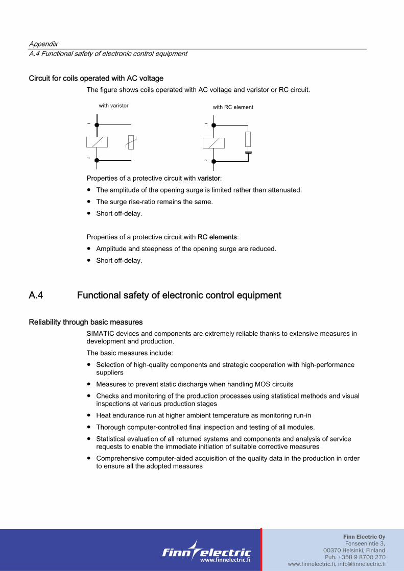
Circuit for coils operated with AC voltage The figure shows coils operated with AC voltage and varistor or RC circuit.
Properties of a protective circuit with varistor: ● The amplitude of the opening surge is limited rather than attenuated.● The surge rise-ratio remains the same.● Short off-delay.
Properties of a protective circuit with RC elements: ● Amplitude and steepness of the opening surge are reduced.● Short off-delay.
A.4 Functional safety of electronic control equipment
Reliability through basic measures SIMATIC devices and components are extremely reliable thanks to extensive measures in development and production. The basic measures include: ● Selection of high-quality components and strategic cooperation with high-performance
suppliers ● Measures to prevent static discharge when handling MOS circuits● Checks and monitoring of the production processes using statistical methods and visual
inspections at various production stages● Heat endurance run at higher ambient temperature as monitoring run-in● Thorough computer-controlled final inspection and testing of all modules.● Statistical evaluation of all returned systems and components and analysis of service
requests to enable the immediate initiation of suitable corrective measures● Comprehensive computer-aided acquisition of the quality data in the production in order
to ensure all the adopted measures
Finn Electric OyFonseenintie 3,
00370 Helsinki, Finland Puh. +358 9 8700 270
www.finnelectric.fi, [email protected]