A27 A28 Cylinder
9
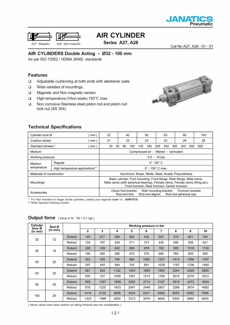
AIR CYLINDER Series A27, A28 Cat No A27, A28 - 01 - 01 AIR CYLINDERS Double Acting - Ø32 - 100 mm As pe r ISO 155 52 / V DMA 2 456 2 stan dard s A27 - Mag netic A28 - Non-magne tic Features Adju stab le cushioni ng at bo th ends with elasto mer pa ds Wide varieties of mountings. Magnetic and Non magnetic version High temperature (Viton seals) 150°C max. Non corrosive Stainless steel piston rod and piston rod lock nut (SS 304) 1.2.1 Output force ( force in N : 1N = 0.1 kgf ) ( Above values have been worked out taking frictional loss into consideration ) Working pressure in bar Cylinder bore Ø (in mm) Rod Ø (in mm) 2 3 4 5 6 7 8 9 10 Extend 145 217 289 362 434 507 579 651 724 32 12 Retract 124 187 249 311 373 435 498 559 621 Extend 226 339 452 565 678 792 905 1018 1130 40 16 Retract 190 285 380 475 570 665 760 855 950 Extend 353 530 706 884 1060 1237 1414 1590 1767 50 20 Retract 297 445 594 742 891 1039 1187 1336 1484 Extend 561 842 1122 1403 1683 1964 2244 2525 2805 63 20 Retract 505 757 1009 1261 1514 1766 2018 2270 2523 Extend 905 1357 1809 2262 2714 3167 3619 4072 4524 80 25 Retract 816 1225 1633 2041 2449 2857 3266 3674 4082 Extend 1414 2120 2828 3534 4241 4948 5655 6362 7069 100 25 Retract 1325 1988 2650 3313 3976 4640 5300 5965 6625 Technical Specifications * For Non standard or lo nger stroke cylinders, co ntact your regional dea ler or JANATICS ** Refer Special Ordering number. Cylinder bore Ø ( mm ) 32 40 50 63 80 100 Cushion stroke ( mm ) 21 23 23 23 28 28 Standard strokes * ( mm ) 25 50 80 100 125 160 200 250 300 320 400 500 Medium Compressed air - filtered - lubricated Working pressure 0.5 - 10 bar Regular 5° - 60° C Medium temperature High temperature applications** 5° - 150° C max. Materials of construction Aluminium, Brass, Nitrile, Steel, Acetal, Polyurethane Mountings Basic cylinder, Foot mounting, Front flange, Rear flange, Male clevis, Male clevis (with spherical bearing), Female clevis, Female clevis (King pin), Front trunnion, Rear trunnion, Centre trunnion Accessories Clevis foot bracket, Wall mounting bracket, Trunnion bracket, Rod end fork, Rod end aligner, Rod end spherical eye
Transcript of A27 A28 Cylinder
7/25/2019 A27 A28 Cylinder
http://slidepdf.com/reader/full/a27-a28-cylinder 1/8
AIR CYLINDERSeries A27, A28
Cat No A27, A28 - 01 - 01
AIR CYLINDERS Double Acting - Ø32 - 100 mm As per ISO 15552 / VDMA 24562 standards
A27 - Magnetic A28 - Non-magnetic
Features
Adjustable cushioning at both ends with elastomer pads
Wide varieties of mountings.
Magnetic and Non magnetic version
High temperature (Viton seals) 150°C max.
Non corrosive Stainless steel piston rod and piston rod
lock nut (SS 304)
1.2.1
Output force ( force in N : 1N = 0.1 kgf )
( Above values have been worked out taking frictional loss into consideration )
Working pressure in barCylinder
bore Ø(in mm)
Rod Ø(in mm) 2 3 4 5 6 7 8 9 10
Extend 145 217 289 362 434 507 579 651 72432 12
Retract 124 187 249 311 373 435 498 559 621
Extend 226 339 452 565 678 792 905 1018 113040 16
Retract 190 285 380 475 570 665 760 855 950
Extend 353 530 706 884 1060 1237 1414 1590 176750 20
Retract 297 445 594 742 891 1039 1187 1336 1484
Extend 561 842 1122 1403 1683 1964 2244 2525 280563 20
Retract 505 757 1009 1261 1514 1766 2018 2270 2523
Extend 905 1357 1809 2262 2714 3167 3619 4072 4524
80 25 Retract 816 1225 1633 2041 2449 2857 3266 3674 4082
Extend 1414 2120 2828 3534 4241 4948 5655 6362 7069100 25
Retract 1325 1988 2650 3313 3976 4640 5300 5965 6625
Technical Specifications
* For Non standard or longer stroke cylinders, contact your regional dealer or JANATICS** Refer Special Ordering number.
Cylinder bore Ø ( mm ) 32 40 50 63 80 100
Cushion stroke ( mm ) 21 23 23 23 28 28
Standard strokes * ( mm ) 25 50 80 100 125 160 200 250 300 320 400 500
Medium Compressed air - filtered - lubricated
Working pressure 0.5 - 10 bar
Regular 5° - 60° CMediumtemperature High temperature applications** 5° - 150° C max.
Materials of construction Aluminium, Brass, Nitrile, Steel, Acetal, Polyurethane
MountingsBasic cylinder, Foot mounting, Front flange, Rear flange, Male clevis,
Male clevis (with spherical bearing), Female clevis, Female clevis (King pin),Front trunnion, Rear trunnion, Centre trunnion
AccessoriesClevis foot bracket, Wall mounting bracket, Trunnion bracket,
Rod end fork, Rod end aligner, Rod end spherical eye
7/25/2019 A27 A28 Cylinder
http://slidepdf.com/reader/full/a27-a28-cylinder 2/8
AIR CYLINDERSeries A27, A28
Cat No A27, A28 - 01 - 01
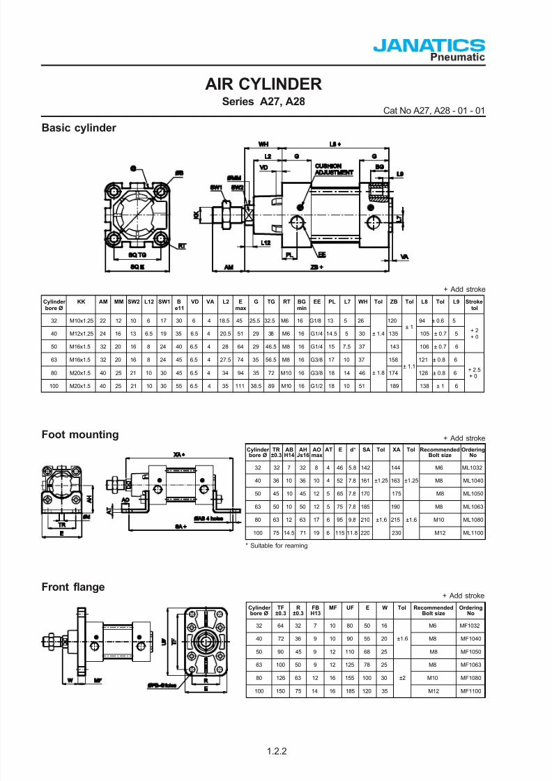
Basic cylinder
+ Add stroke
1.2.2
Foot mounting + Add stroke
* Suitable for reaming
Front flange+ Add stroke
Cylinderbore Ø
TR±0.3
ABH14
AHJs16
AOmax
AT E d* SA Tol XA Tol RecommendedBolt size
OrderingNo
32 32 7 32 8 4 46 5.8 142 144 M6 ML1032
40 36 10 36 10 4 52 7.8 161 163 M8 ML1040
50 45 10 45 12 5 65 7.8 170
±1.25
175
±1.25
M8
ML1050
63 50 10 50 12 5 75 7.8 185 190 M8 ML1063
80 63 12 63 17 6 95 9.8 210 215 M10
ML1080
100 75 14.5 71 19 6 115 11.8 220
±1.6
230
±1.6
M12
ML1100
Cylinderbore Ø
TF±0.3
R±0.3
FBH13
MF UF E W Tol RecommendedBolt size
OrderingNo
32 64 32 7 10 80 50 16 M6 MF1032
40 72 36 9 10 90 55 20 M8
MF1040
50 90 45 9 12 110 68 25
±1.6
M8 MF1050
63 100 50 9 12 125 78 25 M8
MF1063
80 126 63 12 16 155 100 30 M10
MF1080
100 150 75 14 16 185 120 35
±2
M12
MF1100
Cylinderbore Ø
KK AM MM SW2 L12 SW1 Be11
VD VA L2 Emax
G TG RT BGmin
EE PL L7 WH Tol ZB Tol L8 Tol L9 Stroketol
32 M10x1.25 22 12 10 6 17 30 6 4 18.5 45 25.5 32.5 M6 16 G1/8 13 5 26 120 94 ± 0.6 5
40 M12x1.25 24 16 13 6.5 19 35 6.5 4 20.5 51 29 38 M6 16 G1/4 14.5 5 30 135
± 1
105 ± 0.7 5
50 M16x1.5 32 20 16 8 24 40 6.5 4
28 64 29 46.5 M8 16 G1/4 15 7.5 37
± 1.4
143 106 ± 0.7 6
+ 2+ 0
63 M16x1.5 32 20 16 8 24 45 6.5 4 27.5 74 35 56.5 M8 16 G3/8 17 10 37 158 121 ± 0.8 6
80 M20x1.5 40 25 21 10 30 45 6.5 4
34 94 35 72 M10 16 G3/8 18 14 46 174 128 ± 0.8 6
100 M20x1.5 40 25 21 10 30 55 6.5 4
35 111 38.5 89 M10 16 G1/2 18 10 51
± 1.8
189
± 1.1
138 ± 1 6
+ 2.5+ 0
7/25/2019 A27 A28 Cylinder
http://slidepdf.com/reader/full/a27-a28-cylinder 3/8
AIR CYLINDERSeries A27, A28
Cat No A27, A28 - 01 - 01
1.2.3
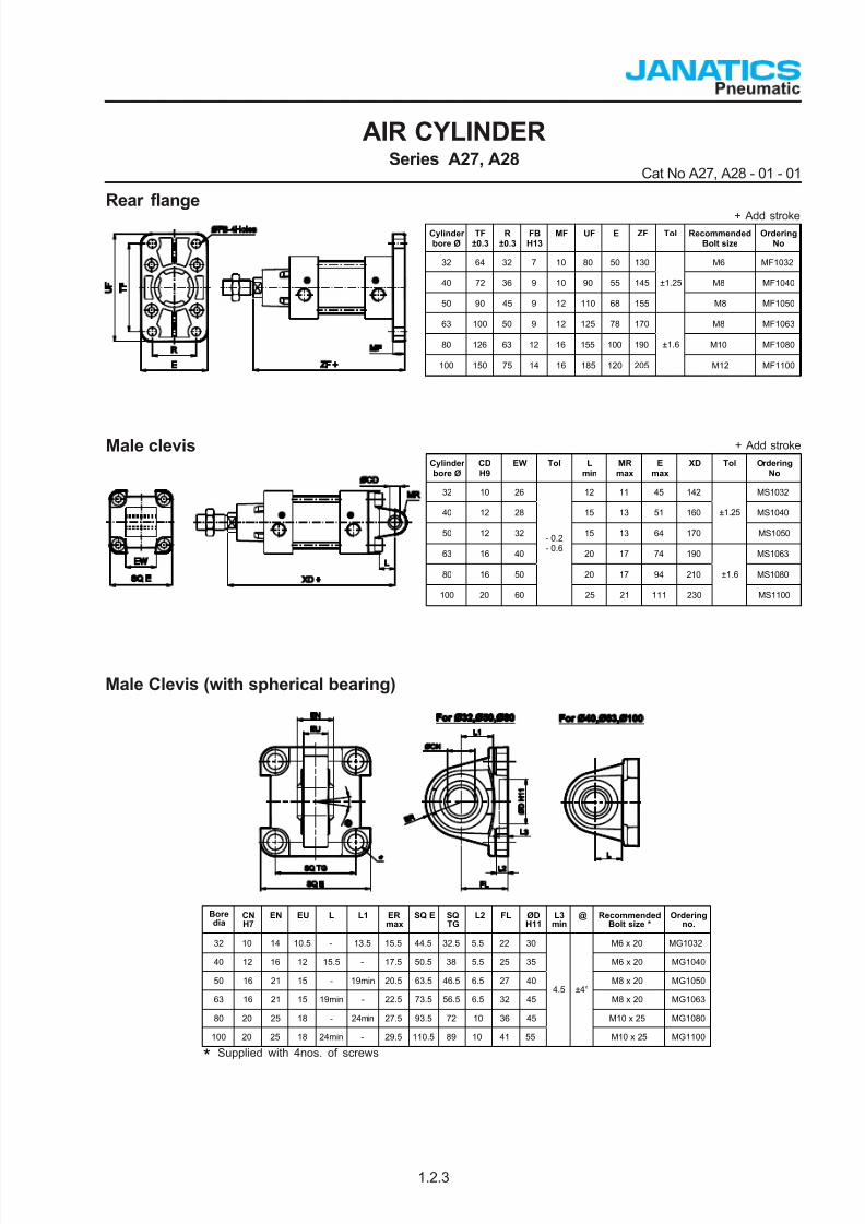
Male clevis + Add stroke
Cylinderbore Ø
CDH9
EW Tol Lmin
MRmax
Emax
XD Tol OrderingNo
32 10 26 12 11 45 142 MS1032
40 12 28 15 13 51 160 MS1040
50 12 32 15 13 64 170
±1.25
MS1050
63 16 40 20 17 74 190 MS1063
80 16 50 20 17 94 210 MS1080
100 20 60
- 0.2- 0.6
25 21 111 230
±1.6
MS1100
+ Add stroke
Rear flange
Cylinderbore Ø
TF±0.3
R±0.3
FBH13
MF UF E ZF Tol RecommendedBolt size
OrderingNo
32 64 32 7 10 80 50 130 M6 MF1032
40 72 36 9 10 90 55 145 M8
MF1040
50 90 45 9 12 110 68 155
±1.25
M8
MF1050
63 100 50 9 12 125 78 170 M8
MF1063
80 126 63 12 16 155 100 190 M10
MF1080
100 150 75 14 16 185 120 205
±1.6
M12
MF1100
Male Clevis (with spherical bearing)
Supplied with 4nos. of screws*
Boredia
CNH7
EN EU L L1 ERmax
SQ E SQTG
L2 FL ØDH11
L3min
@ RecommendedBolt size *
Orderingno.
32 10 14 10.5 - 13.5 15.5 44.5 32.5 5.5 22 30 M6 x 20 MG1032
40 12 16 12 15.5 - 17.5 50.5 38 5.5 25 35 M6 x 20
MG1040
50 16 21 15 - 19min 20.5 63.5 46.5 6.5 27 40 M8 x 20 MG1050
63 16 21 15 19min - 22.5 73.5 56.5 6.5 32 45 M8 x 20
MG1063
80 20 25 18 - 24min 27.5 93.5 72 10 36 45 M10 x 25 MG1080
100 20 25 18 24min - 29.5 110.5 89 10 41 55
4.5 ±4°
M10 x 25
MG1100
7/25/2019 A27 A28 Cylinder
http://slidepdf.com/reader/full/a27-a28-cylinder 4/8
AIR CYLINDERSeries A27, A28
Cat No A27, A28 - 01 - 01
1.2.4
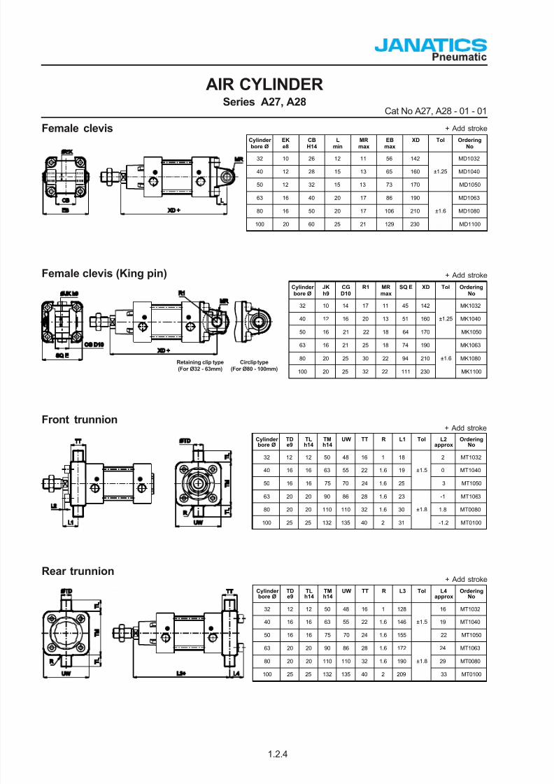
Female clevis + Add stroke
Cylinderbore Ø
EKe8
CBH14
Lmin
MRmax
EBmax
XD Tol OrderingNo
32 10 26 12 11 56 142 MD1032
40 12 28 15 13 65 160 MD1040
50 12 32 15 13 73 170
±1.25
MD1050
63 16 40 20 17 86 190 MD1063
80 16 50 20 17 106 210 MD1080
100 20 60 25 21 129 230
±1.6
MD1100
Female clevis (King pin) + Add stroke
Retaining clip type
(For Ø32 - 63mm)
Circlip type
(For Ø80 - 100mm)
Cylinderbore Ø
JKh9
CGD10
R1 MRmax
SQ E XD Tol OrderingNo
32 10 14 17 11 45 142 MK1032
40 12 16 20 13 51 160 MK1040
50 16 21 22 18 64 170
±1.25
MK1050
63 16 21 25 18 74 190 MK1063
80 20 25 30 22 94 210 MK1080
100 20 25 32 22 111 230
±1.6
MK1100
Front trunnion+ Add stroke
Cylinderbore Ø
TDe9
TLh14
TMh14
UW TT R L1 Tol L2approx
OrderingNo
32 12 12 50 48 16 1 18 2 MT1032
40 16 16 63 55 22 1.6 19 0 MT1040
50 16 16 75 70 24 1.6 25
±1.5
3 MT1050
63 20 20 90 86 28 1.6 23 -1 MT1063
80 20 20 110 110 32 1.6 30 1.8 MT0080
100 25 25 132 135 40 2 31
±1.8
-1.2 MT0100
Rear trunnion+ Add stroke
Cylinderbore Ø
TDe9
TLh14
TMh14
UW TT R L3 Tol L4approx
OrderingNo
32 12 12 50 48 16 1 128 16 MT1032
40 16 16 63 55 22 1.6 146 19 MT1040
50 16 16 75 70 24 1.6 155
±1.5
22 MT1050
63 20 20 90 86 28 1.6 172 24 MT1063
80 20 20 110 110 32 1.6 190 29 MT0080
100 25 25 132 135 40 2 209
±1.8
33 MT0100
7/25/2019 A27 A28 Cylinder
http://slidepdf.com/reader/full/a27-a28-cylinder 5/8
AIR CYLINDERSeries A27, A28
Cat No A27, A28 - 01 - 01
1.2.5
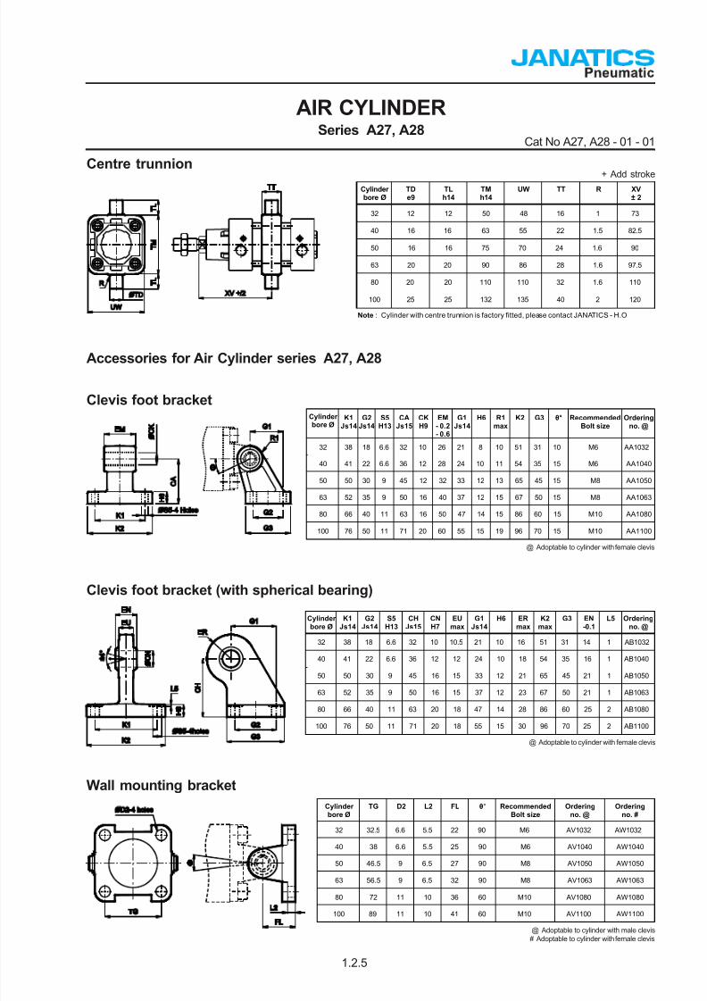
Centre trunnion+ Add stroke
Note : Cylinder with centre trunnion is factory fitted, please contact JANATICS - H.O
Cylinderbore Ø
TDe9
TLh14
TMh14
UW TT R XV± 2
32 12 12 50 48 16 1 73
40 16 16 63 55 22 1.5 82.5
50 16 16 75 70 24 1.6 90
63 20 20 90 86 28 1.6 97.5
80 20 20 110 110 32 1.6 110
100 25 25 132 135 40 2 120
Accessories for Air Cylinder series A27, A28
Clevis foot bracket
@ Adoptable to cylinder with female clevis
Cylinderbore Ø
K1Js14
G2Js14
S5H13
CAJs15
CKH9
EM- 0.2- 0.6
G1Js14
H6 R1max
K2 G3 θ° RecommendedBolt size
Orderingno. @
32 38 18 6.6 32 10 26 21 8 10 51 31 10 M6 AA1032
40 41 22 6.6 36 12 28 24 10 11 54 35 15 M6 AA1040
50 50 30 9 45 12 32 33 12 13 65 45 15
M8
AA1050
63 52 35 9 50 16 40 37 12 15 67 50 15 M8 AA1063
80 66 40 11 63 16 50 47 14 15 86 60 15
M10
AA1080
100 76 50 11 71 20 60 55 15 19 96 70 15
M10
AA1100
Wall mounting bracket
Cylinderbore Ø
TG D2 L2 FL θ° RecommendedBolt size
Orderingno. @
Orderingno. #
32 32.5 6.6 5.5 22 90 M6 AV1032 AW1032
40 38 6.6 5.5 25 90 M6 AV1040 AW1040
50 46.5 9 6.5 27 90
M8 AV1050
AW1050
63 56.5 9 6.5 32 90
M8 AV1063
AW1063
80 72 11 10 36 60 M10 AV1080 AW1080
100 89 11 10 41 60 M10 AV1100
AW1100
@ Adoptable to cylinder with male clevis
# Adoptable to cylinder with female clevis
Clevis foot bracket (with spherical bearing)
@ Adoptable to cylinder with female clevis
Cylinderbore Ø
K1Js14
G2Js14
S5H13
CHJs15
CNH7
EUmax
G1Js14
H6 ERmax
K2max
G3 EN-0.1
L5 Orderingno. @
32 38 18 6.6 32 10 10.5 21 10 16 51 31 14 1 AB1032
40 41 22 6.6 36 12 12 24 10 18 54 35 16 1 AB1040
50 50 30 9 45 16 15 33 12 21 65 45 21 1 AB1050
63 52 35 9 50 16 15 37 12 23 67 50 21 1 AB1063
80 66 40 11 63 20 18 47 14 28 86 60 25 2 AB1080
100 76 50 11 71 20 18 55 15 30 96 70 25 2 AB1100

7/25/2019 A27 A28 Cylinder
http://slidepdf.com/reader/full/a27-a28-cylinder 6/8
AIR CYLINDERSeries A27, A28
Cat No A27, A28 - 01 - 01
1.2.6
Trunnion bracket
Cylinderbore Ø
B1 B2 A d1 d2H13
d3H9
H1 H2 H3 K5Js14
Orderingno.
32 46 18 32 ±0.2 11 6.6 12 30 15 ±0.1 23 71 AT032
40 55 21 36 ±0.2 15 9 16 36 18 ±0.1 27 87 AT040
50 55 21 36 ±0.2 15 9 16 36 18 ±0.1 27 99 AT040
63 65 23 42 ±0.2 16.5 11 20 40 20 ±0.1 29 116 AT063
80 65 23 42 ±0.2 16.5 11 20 40 20 ±0.1 29 136 AT063
100 75 28.5 50 ±0.2 20 14 25 50 25 ±0.1 37 164 AT100
Rod end Fork ( ISO 8140 )
Cylinderbore Ø
KK CE CKf 8
CMB12
LE ERmax
CL Orderingno.
32 M10 x 1.25 40 10 10 20 16 20 AF010
40 M12 x 1.25 48 12 12 24 19 24 AF012
50 / 63 M16 x 1.5 64 16 16 32 25 32 AF016
80 / 100 M20 x 1.5 80 20 20 40 32 40 AF020
Rod end spherical eye ( ISO 8139 )
Cylinderbore Ø
KK CNH9
T ENh12
CE LEmin
ERmax
AX SW Z Orderingno.
32 M10 x 1.25 10 10.5 14 43 15 14 20 17 AP010
40 M12 x 1.25 12 12 16 50 17 16 22 19
13°
AP012
50 / 63 M16 x 1.5 16 15 21 64 22 21 28 22 AP016
80 / 100 M20 x 1.5 20 18 25 77 26 25 33 30/3215°
AP020
Rod end Aligner
Cylinderbore Ø
KK L1 L2 L3 H1 H2 D1 U ± θ° Orderingno.
32 M10 x 1.25 20 14 65 17 8 28 0.75 5 AR010
40 M12 x 1.25 22 18 75 19 10 32 1 5 AR012
50 / 63 M16 x 1.5 25 22 91 27 13 41 1 5 AR016
80 / 100 M20 x 1.5 30 28 112 32 16 50 1.5 5 AR020
7/25/2019 A27 A28 Cylinder
http://slidepdf.com/reader/full/a27-a28-cylinder 7/8
AIR CYLINDERSeries A27, A28
Cat No A27, A28 - 01 - 01
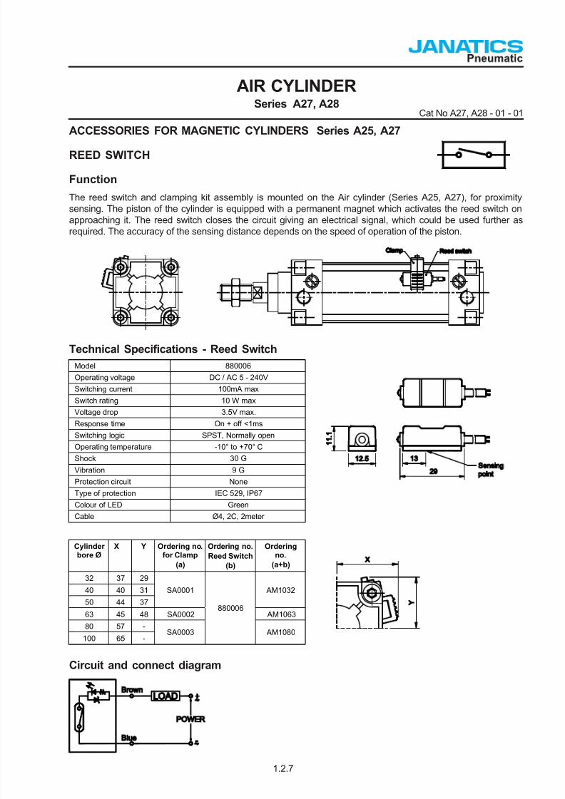
ACCESSORIES FOR MAGNETIC CYLINDERS Series A25, A27
REED SWITCH
Function
The reed switch and clamping kit assembly is mounted on the Air cylinder (Series A25, A27), for proximitysensing. The piston of the cylinder is equipped with a permanent magnet which activates the reed switch onapproaching it. The reed switch closes the circuit giving an electrical signal, which could be used further asrequired. The accuracy of the sensing distance depends on the speed of operation of the piston.
Technical Specifications - Reed Switch
Circuit and connect diagram
Cylinderbore Ø
X Y Ordering no.for Clamp
(a)
Ordering no.
Reed Switch(b)
Orderingno.
(a+b)
32 37 29
40 40 31
50 44 37
SA0001 AM1032
63 45 48 SA0002 AM1063
80 57 -
100 65 -SA0003
880006
AM1080
Model 880006
Operating voltage DC / AC 5 - 240V
Switching current 100mA max
Switch rating 10 W max
Voltage drop 3.5V max.
Response time On + off <1ms
Switching logic SPST, Normally open
Operating temperature -10° to +70° C
Shock 30 G
Vibration 9 G
Protection circuit None
Type of protection IEC 529, IP67
Colour of LED Green
Cable Ø4, 2C, 2meter
1.2.7

7/25/2019 A27 A28 Cylinder
http://slidepdf.com/reader/full/a27-a28-cylinder 8/8
Cylinderbore Ø
Footmounting *
Front / Rearflange *
Male clevis * Femaleclevis *
Front / Reartrunnion *
Female clevis(King pin) *
32 ML1032 MF1032 MS1032 MD1032 MT1032 MK1032
40 ML1040 MF1040 MS1040 MD1040 MT1040 MK1040
50 ML1050 MF1050 MS1050 MD1050 MT1050 MK1050
63 ML1063 MF1063 MS1063 MD1063 MT1063 MK1063
80 ML1080 MF1080 MS1080 MD1080 MT0080 MK1080
100 ML1100 MF1100 MS1100 MD1100 MT0100 MK1100
Note :
If ordered as 40 dia, 50 mm stroke cylinder, Basic cylinder A28 040 050 O will be supplied.
For repeat order when the details are taken from cylinder nameplate, mention the mounting style separately.
For ordering Accessories refer corresponding tables for ordering numbers.
For ordering individual Mounting kits ( If needed separately ) the order numbers are as below
Example :
Ordering no. for standard cylinder with 40 dia bore, 50 mm stroke with female clevis mounting with High temp:A28 040 050 D - T
How to order
Subject to change
AIR CYLINDERSeries A27, A28
Cat No A27, A28 - 01 - 01
1.2.8
For your special requirements of cylinders or for further informations contact your regional dealer or JANATICS
Supplied with 4nos. of screws*
A
Model
27 Magnetic cylinder
28 Standard cylinder
Piston Ø (mm)
032 - Ø 32
040 - Ø 40
050 - Ø 50
063 - Ø 63
080 - Ø 80
100 - Ø 100
Stroke (mm)
025 - 25
050 - 50
080 - 80
100 - 100
125 - 125
160 - 160
200 - 200
250 - 250300 - 300
320 - 320
400 - 400
500 - 500
Special Cylinders
H - High temp
S - SS piston rod
Mountings
O - Basic
L - Foot Mounting
F - Front Flange
R - Rear Flange
S - Male Clevis
G - Male Clevis(with spherical bearing)
D - Female Clevis
K - Female Clevis(King pin)
M - Rear Trunnion
N - Front Trunnion
T - Center Trunnion