A2-103 Smart Monitoring of Power Transformers: Project Update
10
[email protected] Smart Monitoring of Power Transformers: Project Update T. K. SAHA* 1 , D. MARTIN 1 , H. MA 1 , C. EKANAYAKE 1 , G. RUSSELL 2 , G. BUCKLEY 3 , T. GRAY 4 , G. CALDWELL 5 1 The University of Queensland, 2 Powerlink, 3 Energex, 4 TransGrid, 5 Ergon Energy Australia SUMMARY Many power transformers are reaching the end of their useful lives. A utility then faces the decision of when to replace them. If the replacement occurs too soon this is financially inefficient, where the costs are ultimately passed on to the consumer. However if the utility delays replacement too late a failure may occur, resulting in an expensive and potentially dangerous situation. Determining an appropriate balance is challenging, and requires the monitoring of the power transformer fleet which is a complex task requiring a highly skilled professional workforce. Many different tests can be performed on a transformer. However, diagnosing a fault from a variety of results and making a condition assessment of the whole unit can be technically challenging. A transformer smart monitoring system, the SmartBox, has been developed at the University of Queensland (UQ) to provide an effective visibility of a transformer’s condition from many different types of online and offline sensors, determine the life remaining of the winding paper insulation, and provide an overall health condition. The SmartBox comprises an industrial PC, measurement transducers and UQ developed software, and is designed to operate within the substation environment. The work that will be reported in this paper are the result of the experiences that industry partners Energex, Ergon Energy, Powerlink Queensland and TransGrid had with using this device. The SmartBox system monitors the parts of a transformer which have been found to be at highest risk of causing failure, e.g. oil quality and insulation condition. The SmartBox monitors these problems using: Dissolved Gas Analysis (DGA), Partial Discharge (PD), acoustic and vibration signatures, water activity of oil, and other various tests. The goal has been to produce a suite of algorithms, which diagnose the life remaining of the transformer and the propensity for failure of a component to occur. KEYWORDS Insulation, oil characteristics, pattern recognition, and power transformer A2-103 CIGRE 2016 21, rue d’Artois, F-75008 http : //www.cigre.org
Transcript of A2-103 Smart Monitoring of Power Transformers: Project Update

Smart Monitoring of Power Transformers: Project Update
T. K. SAHA*1, D. MARTIN1, H. MA1, C. EKANAYAKE1, G. RUSSELL2, G. BUCKLEY3, T. GRAY4, G. CALDWELL5
1The University of Queensland, 2Powerlink, 3Energex, 4TransGrid, 5Ergon Energy
Australia
SUMMARY Many power transformers are reaching the end of their useful lives. A utility then faces the decision of when to replace them. If the replacement occurs too soon this is financially inefficient, where the costs are ultimately passed on to the consumer. However if the utility delays replacement too late a failure may occur, resulting in an expensive and potentially dangerous situation. Determining an appropriate balance is challenging, and requires the monitoring of the power transformer fleet which is a complex task requiring a highly skilled professional workforce. Many different tests can be performed on a transformer. However, diagnosing a fault from a variety of results and making a condition assessment of the whole unit can be technically challenging. A transformer smart monitoring system, the SmartBox, has been developed at the University of Queensland (UQ) to provide an effective visibility of a transformer’s condition from many different types of online and offline sensors, determine the life remaining of the winding paper insulation, and provide an overall health condition. The SmartBox comprises an industrial PC, measurement transducers and UQ developed software, and is designed to operate within the substation environment. The work that will be reported in this paper are the result of the experiences that industry partners Energex, Ergon Energy, Powerlink Queensland and TransGrid had with using this device. The SmartBox system monitors the parts of a transformer which have been found to be at highest risk of causing failure, e.g. oil quality and insulation condition. The SmartBox monitors these problems using: Dissolved Gas Analysis (DGA), Partial Discharge (PD), acoustic and vibration signatures, water activity of oil, and other various tests. The goal has been to produce a suite of algorithms, which diagnose the life remaining of the transformer and the propensity for failure of a component to occur. KEYWORDS
Insulation, oil characteristics, pattern recognition, and power transformer
A2-103 CIGRE 2016
21, rue d’Artois, F-75008
http : //www.cigre.org

1
1. INTRODUCTION The first step of development was to conduct the research which would ultimately lead to improvements in the algorithms used to monitor a transformer. An extensive programme of research was carried out within the laboratories at UQ, focussing on aspects such as determining faults from PD signatures, measuring the exchange of water between oil and paper insulation, and analysing test data from three test transformers run to their end of life using laboratory conditions. The next step was to design the framework for the system. The challenge was to interpret the many types of data to determine the overall condition of the transformer. The basic functional diagram of the system is shown in Figure 1(a). The types of tests used in the analysis of the transformer’s health are shown in Figure 1(b). As can be seen, two databases are used for information management.
Figure 1. (a) System Framework of SmartBox [1]; (b) Functional Modules of SmartBox.
The major components of the SmartBox system are described in the following sections: estimating the life remaining of insulation paper; measuring water in transformer insulation for the life remaining model; offline dielectric response measurement, advanced signal processing and pattern recognition for PD measurement of transformer, and data and information fusion for evaluating overall health condition of transformer. 2. ESTIMATING LIFE REMAINING OF INSULATION PAPER The condition of paper is quantified using its degree of polymerization. A kinetic equation has been used to relate a change in DP to an ageing period and temperature [2]-[6], (1). The DPstart is taken as 1,000, around that of the paper after the manufacture of a transformer, DPageing period is the DP after a given time in hours. The activation energy, Ea, is the minimum energy, in

2
terms of J/mol, required to start the reaction. The term A is in units of 1/time (hours). The term R is the ideal gas constant, 8.314 J mol-1 K-1. Temperature T is in kelvin. The availability of water and oxygen affect the rate of ageing by changing the A coefficient, polynomial equations to estimate the A coefficient for different levels of water and oxygen have been proposed in [5]-[6], which were used to construct Figure 2.
(1)
Figure 2. Relationship between A value and water content of paper.
A software tool was developed to estimate the time remaining for transformer insulation paper. The DP of the paper within a transformer can be estimated from the furan content of its oil. The ‘A coefficient’ is estimated from measuring the water content of the insulation, and the availability of oxygen depends on the transformer tank being sealed or not. The temperature of the insulation is calculated using the IEC60076/7 thermal model [7] and the expected average future load of the transformer. An advantage of using load is that the utility can investigate the effect of different usage strategies on the life remaining of the unit. This software tool is shown in Figure 3.
Figure 3. Life remaining calculator software.
A dynamic life remaining model can be produced using (1), where the loss in paper DP is tracked over time. Equation (1) is rearranged into (2). Where the start DP is known, for instance estimated using furans, the new DP after a period of ageing is known.
(2)
The life lost is calculated by dividing the ageing period by the expected life at that temperature, (3). The expected life at a given temperature is found by rearranging (1) to
0
1E+09
2E+09
3E+09
4E+09
5E+09
6E+09
7E+09
8E+09
9E+09
1% 2% 3% 4%
A value (h
‐1)
Water content of paper
High
Medium
Low
Oxygen level

3
calculate the ageing period where equals 1000 and is 200. Life lost after time period , , is therefore shown by (3).
(3)
The total life lost after a number of time intervals, is shown in (4). is 1 for a new transformer and slowly falls until it reaches 0, when there is no life left in the paper.
1 ∑ (4)
3. DETERMINATION OF WATER CONTENT OF PAPER In order to properly determine remnant life, the water content of paper (WCP) must be known. Consequently, a software tool to measure WCP was created and tested on four utilities’ power transformers. The fundamental equations are outlined below, and a full discussion is given in the authors’ articles [8] – [9]. Water activity Aw is measured in the oil by an installed sensor. Aw is equal to the vapour pressure of the dissolved water (Pv) divided by the vapour pressure above pure water at that temperature (P0) (5). Since P0 can be calculated using the Buck equation (6) [10], (5) can be rearranged into (7).
(5)
6.1121.. (6)
0.00603.. (7)
Once Pv is calculated the Fessler equation (8) [11] is used to calculate WCP. Since the temperature and vapour pressure of the surface of the paper is required, which is likely to be at a temperature higher than that of the oil, the vapour pressure is recalculated for the different temperature. A long term averaging function is applied to WCP.
2.173 10 ..
(8) A software tool was set up to determine WCP from water activity probe measurements, shown in Figure 4. To test the proposed algorithm, water activity probes (Vaisala MMT330) were set up on four power transformers operated by the utilities (Tr1 – Tr4). The WCP of these transformers was measured both using dielectric response and the water activity based algorithm. The results are shown in Table I. As can be seen, the measurements are in close agreement.
Figure 4. WCP calculation software.

4
Table I Comparison of dielectric response measurements and UQ method. Tr1 Tr2 Tr3 Tr4
Unit description(MVA) 12.5 12.5 25 225/375 Age on test(years) 33 33 29 7
Water content measured using dielectric response (%)
3.9 3.01 – 3.62 3.7 0.3
Water content measured using UQ algorithm and water activity sensor (%)
3.8 3.7 2.7 – 2.9 0.4
1 First measurement, 2 Second measurement 4. OFFLINE DIELECTRIC RESPONSE MEASUREMENT UQ has been working on dielectric measurement for the last twenty years. This includes both time domain and frequency domain measurements. In time domain measurement, initially recovery voltage measurement was investigated. Later much emphasis has been given on polarisation/depolarisation current (PDC) measurement. UQ has developed its own equipment, which can perform both Recovery Voltage Measurement (RVM) and PDC measurements. On top of that commercially available frequency domain dielectric spectroscopy (FDS) measurement systems has been used in laboratory and field environment.
The interpretation of PDC data depends on analysing the polarisation/depolarisation currents from which conductivities of oil and paper are calculated separately. Based on past transformer data and experimental measurements in accelerated ageing conditions, a number of software tools are developed to estimate the moisture condition and overall ageing of transformer.
FDS interpretation is mainly based on the X-Y model, which counts the geometrical configuration of the transformer and variation of dielectric response of individual insulating material with moisture and temperature. As geometrical information of most of the old transformers is unavailable the program itself estimates both geometrical parameters and moisture content of the solid insulation. FDS interpretation schemes have been improved to understand the response of aged insulation and the effect of the temperature variations during the measurements as well as temperature distribution of the transformer. Moreover, other commercial software tools are used to check the accuracy of developed FDS interpretations.
Moisture dynamics and its effects on the dielectric response of a transformer’s cellulose insulation have been extensively investigated and proposed a distributed parameter model to reveal the correlation between moisture distribution under non-equilibrium conditions due to thermal transients and dielectric response parameters of cellulose insulation. The proposed model has been verified with laboratory based accelerated ageing and moisture diffusion experiments on a prototype transformer. Based on this study a software tool has been developed to accurately estimate the moisture content using available dielectric response data of the transformers as illustrated in Figure 5. Further details of this work can be obtained from [12]. The added advantage of the proposed method is that it is able to provide moisture distribution in transformer insulation in addition to the average moisture content.
To illustrate some comparison of different techniques utilised for estimating moisture content, Table 1 presents the estimated moisture content from FDS method and water activity sensor for four different transformers. Further details on these techniques can be obtained from [12-18]. FDS is an offline diagnostic technique, which provides an average moisture content of transformer insulation system. Online water activity sensors (Vaisala probe and the Fessler equation as described in Section 3) need to be installed for a few weeks to obtain an accurate

5
measurement. Whereas, dielectric response is useful if a measurement is required in several hours (although the transformer must be disconnected from the network).
Figure 5. Architecture of the proposed software tool to consider moisture dynamics in FDS estimates [12] 5. ADVANCED SIGNAL PROCESSING AND PATTERN RECOGNITION FOR PD MEASUREMENT OF TRANSFORMER Partial discharges (PD) measurement can provide important information when the measured PD events significantly exceed the pre-defined thresholds. The SmartBox system can be connected to various types of PD sensors. A variety of signal processing and pattern recognition algorithms have been deployed to the SmartBox. These algorithms can be categorized into four groups as shown in Figure 6 [19]:
1. PD signal extraction algorithm to remove noise from the original measured PD signals and identify the significant PD events.
2. Feature extraction algorithm for extracting the characteristics from raw PD data. 3. Multi PD source separation algorithm for differentiating multiple PD sources. 4. PD source classification algorithm for identifying the types of PD sources.
Figure 6. Online PD monitoring and diagnosis procedures.

6
To extract PD signals from noise, a number of signal processing algorithms have been developed for the SmartBox [20 - 23]. One of such algorithms is wavelet transform (WT), which is implemented through (1) selecting a suitable mother wavelet and decomposing measured signals into wavelet coefficients at different levels; (2) applying thresholds to retain the coefficients related to PD signals and discard the coefficients associated with noise; and (3) reconstructing PD signals using the remaining coefficients [20].
Improper selection of mother wavelet and threshold can compromise the wavelet transform’s performance. As an alternative to wavelet transform, empirical model decomposition (EMD) is developed. EMD does not require selecting mother wavelets since it uses the local characteristic time scale of the signal itself. EMD decomposes the measured signal into a number of mono-component signals (intrinsic mode functions, IMFs). To further enhance EMD, other techniques are also developed for the SmartBox [20-22].
To characterize PD signal, the phase-resolved PD (PRPD) diagram has been widely adopted [20]. In a PRPD diagram, the AC cycle of the applied voltage is divided into a number of phase windows and the distribution of PD signals’ magnitudes and number counts are drawn. PRPD can provide a characteristic representation of PD signals acquired from PD measurement of transformer for subsequent PD source recognition [23].
Multiple PD sources may co-exist in a transformer. To recognize PD sources involved in discharge, it firstly needs to separate these sources and a time-frequency (TF) map concept can be adopted to fulfil this task [24, 25]. An enhanced version of TF map, named as TF sparsity map was developed for the SmartBox system. The TF sparsity map consists of the following steps [24]:
1. PD pulses are extracted and decomposed in joint time-frequency domains. 2. Sparsity values are calculated from the decomposed signals. There are two sparsity values
for each decomposed signal (one for time domain and another for frequency domain). 3. Sparsity trends (the variations of the sparsity values) are calculated. Sparsity trends are
unique to represent a group of PD pulses originated from a particular PD source. The roughness value (arithmetic average of absolute values of sparsity trends) for a single PD pulse is computed.
4. Form the TF sparsity map by projecting roughness values (both time and frequency domains) of PD pulses onto a two-dimensional (2D) plane.
After PD source separation, another task is to use pattern recognition algorithm to classify the PD source that cause discharge inside the transformer, i.e. identifying whether the PD activities are caused by internal discharge or protrusions (corona) or surface discharge or bubbles in the oil or drifting metal particles.
The pattern recognition algorithm is firstly trained on a database, in which the algorithm constructs a model to approximate the underlying relationship between the characteristics of PD signals in the database and the corresponding PD source types. After training, the PD signals obtained from PD measurement of field transformer are fed into the algorithm and are classified into one type of PD sources. In the SmartBox, a number of artificial neural network and support vector machine algorithms have been developed for PD sources classification.
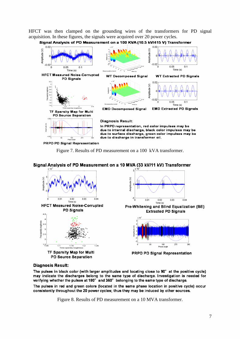
Figures 7 and 8 present the results of applying the above PD signal analysis techniques to process signals acquired from online PD measurements on two transformers. The 100 kVA (10.5 kV/415 V) transformer is located in laboratory while the 10 MVA (33 kV/11 kV) transformer is located in a substation of the local distribution authority. Before conducting PD measurements, a HFCT was first placed on the ground close to the transformers and the SmartBox system was used to record environmental signals (e.g. interference and noise). The
7
HFCT was then clamped on the grounding wires of the transformers for PD signal acquisition. In these figures, the signals were acquired over 20 power cycles.
Figure 7. Results of PD measurement on a 100 kVA transformer.
Figure 8. Results of PD measurement on a 10 MVA transformer.

8
6. DATA AND INFORMATION FUSION As presented in the above sections, with the SmartBox system, a variety of offline and online diagnostic measurements have been successfully applied to monitoring and evaluating different aspect of transformer condition. The challenge was to integrate all the information from these measurements to make an explicit condition assessment on transformers (refer to Figure 1). Currently a Bayesian Network (BN) based data and information fusion method is under development for the SmartBox system. The BN based data and information fusion is tasked to provide an overall health condition assessment of a transformer using data and information obtained from different transformer diagnostic measurements. In this method, statistical approaches including Monte Carlo simulation and Bootstrap are employed for extracting most relevant but not redundant information from multiple diagnostic measurements. Then the information extracted from different measurements is aggregated to provide transformer health condition. Figure 9 is a conceptual diagram of the BN-based data and information fusion method [26].
Figure 9. Bayesian Fusion (BN) based data and information fusion for transformer condition monitoring and diagnosis [26].
7. CONCLUSIONS Computerised monitoring techniques can automatically process large amounts of data, extract useful information regarding a transformer’s condition and suggest remedial action if required, and determine both an estimation of the life remaining and whether any prevailing conditions could lead to future faults. BIBLIOGRAPHY [1] H.Ma, T.Saha, C.Ekanayake, and D.Martin, “Smart Transformer for Smart Grid – Intelligent Framework
and Techniques for Power Transformer Asset Management,” IEEE Transactions on Smart Grid, Vol. 6, No.2, 2015.
[2] A. M. Emsley, X. Xiao, R. J. Heywood, and M. Ali, “Degradation of cellulosic insulation in power transformers. Part 3: Effects of oxygen and water on ageing in oil,” Proc. IEE Sci., Measure. Techn., Vol. 147, pp. 115-119, 2000.

9
[3] L. E. Lundgaard, W. Hansen, D. Linhjell, and T. J. Painter, "Aging of oil-impregnated paper in power transformers,” IEEE Transactions on Power Delivery, Vol. 19, pp. 230-239, 2004.
[4] N. Lelekakis, D. Martin & J. Wijaya , “Ageing Rate of Paper Insulation used in Power Transformers. Part 1: oil/paper system with low oxygen concentration,” IEEE Transactions on Dielectrics and Electrical Insulation, Nov/Dec 2012.
[5] N. Lelekakis, D. Martin & J. Wijaya , “Ageing Rate of Paper Insulation used in Power Transformers. Part 2: oil/paper system with medium and high oxygen concentration,” IEEE Transactions on Dielectrics and Electrical Insulation, Nov/ Dec 2012.
[6] D. Martin, Y. Cui, C. Ekanayake, H. Ma, and T. Saha, “An Updated Model to Determine the Life Remaining of Transformer Insulation,” IEEE Transactions on Power Delivery, Vol. 30, No.1, 2015.
[7] IEC 60076-7, “Power transformers - Part 7: Loading guide for oil-immersed power transformers,” Switzerland, 2005.
[8] D. Martin, T. Saha, R. Dee, G. Buckley, S.Chinnarajan, G. Caldwell, J. Zhou, G. Russell, “Determining Water in Transformer Paper Insulation: Analysing Aging Transformers,” IEEE Electr. Insul. Mag., pp. 23–32, Sep/Oct. 2015.
[9] D. Martin, T. Saha, T. Gray, and K. Wyper, “Determining water in transformer paper insulation: Effect of measuring oil water activity in different locations,” IEEE Electr. Insul. Mag., pp. 18–25, May/Jun. 2015.
[10] A. L. Buck, “New equations for computing vapour pressure and enhancement factor,” J. Appl. Met., vol. 20, pp. 1527–1532, 1981.
[11] W. A. Fessler, O. Rouse, W. J. McNutt, and O. R. Compton, “A refined mathematical model for prediction of bubble evolution in transformers,” IEEE Transactions on Power Delivery, vol. 4, no. 1, pp. 391–404, Jan. 1989.
[12] Y.Cui, H.Ma, T.Saha, and C.Ekanayake, “Understanding moisture dynamics and its effect on dielectric response of transformer insulation,” IEEE Transactions on Power Delivery, vol. 30 no. 5, Oct 2015.
[13] R.Jadav, C.Ekanayake, and T.Saha, “Understanding the impact of moisture and ageing of transformer insulation on frequency domain spectroscopy,” IEEE Transactions on Dielectrics and Electrical Insulation, vol.21, no. 1, 2014.
[14] T.Saha and P.Purkait, “Investigation Of Polarization And Depolarization: Current Measurements For The Assessment Of Oil-Paper Insulation Of Aged Transformers,” IEEE Transactions on Dielectrics and Electrical Insulation, vol.11, no.1, 2004.
[15] T.K.Saha, “Review of time-domain polarization measurements for assessing insulation condition in aged transformers,” IEEE Transactions On Power Delivery, vol. 18, no. 4, 2003.
[16] T.Saha, Tapan, “Review Of Modern Diagnostic Techniques For Assessing Insulation Condition In Aged Transformers,” IEEE Transactions on Dielectrics and Electrical Insulation, vol.10, no. 5, 2003.
[17] T.Saha and P.Purkait, “Investigations of temperature effects on the dielectric response measurements of transformer oil-paper insulation system,” IEEE Transactions on Power Delivery, vol. 23, no.1, 2008.
[18] T.Saha and P.Purkait, “Investigation of an Expert System for Condition Assessment of Transformer Insulation Based on Dielectric Response Measurements,” IEEE Transactions on Power Delivery, vol.19, no. 3, 2004.
[19] H.Ma, J.C.Chan, T.K.Saha, and C.Ekanayake, “Pattern Recognition Techniques and Their Applications for Automatic Partial Discharge Source Classification,” IEEE Transactions on Dielectrics and Electrical Insulation, vol. 20, no.2, 2013.
[20] J.C.Chan, H.Ma, T.K.Saha, and C.Ekanayake, “Self-Adaptive Partial Discharge Signal Extraction Based on Ensemble Empirical Mode Decomposition and Optimal Morphological Thresholding,” IEEE Transaction on Dielectrics and Electrical Insulation, vol.21, no.1, 2014.
[21] J.C.Chan, H.Ma, and T.Saha, “Automatic Blind Equalization and Morphological Thresholding for Partial Discharge Signal De-noising,” IEEE Transaction on Power Delivery, vol. 29, no.4, 2014.
[22] J.C.Chan, H.Ma, and T.Saha, " A Hybrid Method on Signal De-noising and Representation for Online Partial Discharge Monitoring of Power Transformers at Substations," IET Science, Measurement & Technology, vol.9, no.7, 2015.
[23] J.Seo, H.Ma, and T.Saha, “Probabilistic Wavelet Transform for Partial Discharge Measurement of Transformer,” IEEE Transaction on Dielectrics and Electrical Insulation, vol. 22, no.2, 2015.
[24] J.C.Chan, H.Ma and T.Saha, “Automatic Partial Discharge Source Separation for Power Transformer Condition Assessment,” IEEE Transaction on Dielectrics and Electrical Insulation, vol.22, no.4, 2015.
[25] A. Cavallini, X. Chen, G. Montanari, and F. Ciani, "Diagnosis of EHV and HV transformers through an innovative partial-discharge-based technique," IEEE Transaction on Power Delivery, vol. 25, pp. 814-824, 2010.
[26] Y.Cui, H.Ma, and T.Saha, “Multi-Source Information Fusion for Power Transformer Condition Assessment,” submitted to IEEE P IEEE Power and Energy Society 2016 General Meeting.