A15VSO Replaces: –.– English Series 10 2230 Directive for the systematic calculation of high...
52
Instruction manual RE 92800-01-B/10.10 Replaces: –.– English Axial Piston Variable Pump A15VSO Series 10
Transcript of A15VSO Replaces: –.– English Series 10 2230 Directive for the systematic calculation of high...

Instruction manual
RE 92800-01-B/10.10Replaces: –.–English
Axial Piston Variable Pump A15VSOSeries 10
The data specified above only serve to describe the product. No statement about a specific char-acteristic or suitability for a certain application can be derived from this information. The information given does not release the user from the obliga-tion of own judgment and verification. It must be remembered that our products are subject to a natural process of wear and aging.
© This document, as well as the data, specifica-tions and other information set forth in it, are the exclusive property of Bosch Rexroth AG. It may not be reproduced or given to third parties without its consent.
The cover shows an example application. The product delivered may differ from the image on the cover.
The original instruction manual is created in the German language.

RE 92800-01-B/10.10 | A15VSO Series 10 Bosch Rexroth AG 3/52
Contents
Contents1 About this manual ..........................................................................................4
1.1 Related documents ...................................................................................41.2 Abbreviations used ...................................................................................5
2 General safety instructions ...........................................................................62.1 Intended use .............................................................................................62.2 Improper use .............................................................................................62.3 Personnel qualifications ............................................................................72.4 Safety instructions in this manual .............................................................72.5 Adhere to the following instructions ..........................................................82.6 Operator's obligations ...............................................................................9
3 Delivery contents ..........................................................................................104 Product description ......................................................................................11
4.1 Performance description .........................................................................114.2 Device description...................................................................................114.3 Product identification...............................................................................13
5 Transport and storage ..................................................................................145.1 Transporting the axial piston unit ............................................................145.2 Storing the axial piston unit .....................................................................16
6 Installation .....................................................................................................186.1 Unpacking ...............................................................................................186.2 Installation conditions..............................................................................186.3 Installation position .................................................................................206.4 Installing the axial piston unit ..................................................................24
7 Commissioning .............................................................................................337.1 First commissioning ................................................................................337.2 Recommissioning after standstill ............................................................367.3 Running-in phase ....................................................................................37
8 Operation .......................................................................................................389 Maintenance and repair ................................................................................39
9.1 Cleaning and care ...................................................................................399.2 Inspection................................................................................................399.3 Maintenance ...........................................................................................409.4 Repair .....................................................................................................409.5 Spare parts .............................................................................................40
10 Decommissioning .........................................................................................4111 Removal and replacement ...........................................................................41
11.1 Required tools .........................................................................................4111.2 Preparing for removal .............................................................................4111.3 Removing the axial piston unit ................................................................4111.4 Preparing the components for storage or further use .............................42
12 Disposal .........................................................................................................4312.1 Environmental protection ........................................................................43
13 Extension and conversion ...........................................................................4314 Troubleshooting ...........................................................................................44
14.1 How to proceed for troubleshooting ........................................................4414.2 Malfunction table .....................................................................................45
15 Technical data ...............................................................................................4716 Appendix .......................................................................................................47
16.1 Address directory ...................................................................................4717 Alphabetical index ........................................................................................48

4/52 Bosch Rexroth AG A15VSO Series 10 | RE 92800-01-B/10.10
About this manual
About this manual1 This manual contains important information on the safe and appropriate installation, transport, commissioning, maintenance, removal and simple troubleshooting of the A15VSO axial piston variable pump Series 10.
Read this manual completely, especially chapter "2 General safety finstructions", before working with the A15VSO axial piston variable pump.
1.1 Related documentsThe A15VSO axial piston variable pump is a system component. Also observe the manuals for the other system components.Further information on the A15VSO axial piston variable pump, its installation and operation can be found in the Rexroth documents listed in the following table.
Related documentsTable 1: Related documents ContentsOrder confirmation Contains the preset technical data of your A15VSO axial
piston variable pump.Installation drawing Contains the outer dimensions, all connections and the
hydraulic circuit diagram for your A15VSO axial piston variable pump .
Data sheet RE 92800 Contains the permissible technical data for the A15VSO axial piston variable pump series 10.
Data sheet RE 90220 Describes the requirements on a mineral-oil based hydraulic fluid and related hydrocarbons for the operation with Rexroth hydraulic components, and assists you in selecting a hydraulic fluid for your system.
Data sheet RE 90221 Describes the requirements on an environmentally acceptable hydraulic fluid for operation with Rexroth hydraulic components and assists you in selecting a hydraulic fluid for your system.
Data sheet RE 90223 Contains additional information on the use of Rexroth axial piston units with HF hydraulic fluids.
Data sheet RE 90300-03-B Contains additional information on the use of Rexroth axial piston units at low temperatures.
Also observe the generally applicable, legal or otherwise binding regulations of the European and national legislation and the rules for the prevention of accidents and for environmental protection applicable in your country.

RE 92800-01-B/10.10 | A15VSO Series 10 Bosch Rexroth AG 5/52
About this manual
Abbreviations used1.2 As umbrella term for "A15VSO axial piston variable pump", the designation "axial piston unit" will be used in the following.Table 2: AbbreviationsAbbreviation MeaningA15VSO Axial piston variable pump, open circuits
DIN Deutsche Industrie Norm (German Institute for Standardization)
ISO International Organization for Standardization
RE Rexroth document in the English language
VDI 2230 Directive for the systematic calculation of high duty bolted joints and joints with one cylindrical bolt from the VDI (Verein Deutscher Ingenieure - Association of German Engineers)
6/52 Bosch Rexroth AG A15VSO Series 10 | RE 92800-01-B/10.10
General safety instructions
2 General safety instructionsThe axial piston unit has been manufactured according to the generally accepted rules of current technology. There is, however, still a danger of personal injury or damage to equipment if the following general safety instructions and the warnings before the steps contained in this manual are not complied with.
Read this manual completely and thoroughly before starting work with the faxial piston unit.Keep this manual in a location where they are accessible to all users at all ftimes.Always include the instruction manual when you pass the axial piston unit on fto third parties.
Intended 2.1 useAxial piston units are hydraulic components, meaning that in their application they are classified neither as complete nor as incomplete machines in the sense of the EU machine directive 2006/42/EC. A component is exclusively intended to form an incomplete or a complete machine together with other components. The component may only be commissioned after it has been installed in the machine/system for which it is intended.The axial piston unit is only approved as a pump for hydrostatic drives in an open circuit. Motor mode is also permissible on the version with mooring control.
Observe the technical data, application operating conditions and performance flimits as specified in data sheet RE 92800 and in the order confirmation. Information about approved hydraulic fluids can be found in data sheet RE 92800.
The axial piston unit is only intended for professional use and not for private use.Intended use includes having read and understood this documentation, especially the chapter "2 General safety instructions".
Improper use2.2 Any use other than that described as intended use shall be considered as improper and is therefore impermissible.If unsuitable products are installed or used in applications that are of relevance to safety, unexpected operating conditions may occur in the application which could result in injury to persons or property damage. For this reason, products should only be used in safety-relevant applications if this usage is expressly specified and approved in the documents related to the product. For example, in ex-protection areas or in safety-related parts of a control system (functional safety).Bosch Rexroth AG shall accept no liability whatsoever for damages resulting from improper use. The user shall bear all risks arising from improper use.Similarly, the following predictable faulty usages are also considered to be not as intended:
Using the axial piston unit in an explosive environment •Use of non-approved fluids as stated on data sheet RE 92800, e.g. water or •polyurethane components.Modification of factory settings by non-authorized persons •Using axial piston unit fittings (e.g. mountable filter, control unit, valves) for •other applicationsUsing the axial piston unit under water at a depth of more than 10 meters •Using the axial piston unit in aircraft or space craft •
RE 92800-01-B/10.10 | A15VSO Series 10 Bosch Rexroth AG 7/52
General safety instructions
Using with a sustained pressure differential between • exterior and interior pressure of more than 6 bar with the exterior pressure greater than the interior pressure (case pressure).Using the axial piston unit in an aggressive atmosphere •Using outside the operating parameters approved in the data sheet (unless •special approval has been granted)
2.3 Personnel qualificationsInstallation, commissioning and operation, removal, care and maintenance require basic mechanical, hydraulic and electrical knowledge, as well as knowledge of the appropriate technical terms. For transporting and handling the product, additional knowledge is necessary with regard to working with a lifting device and the corresponding attachment equipment. In order to ensure operating safety, these activities may therefore only be carried out by qualified personnel or an instructed person under the direction and supervision of qualified personnel.Qualified personnel are those who can recognize possible hazards and institute the appropriate safety measures due to their professional training, knowledge, and experience, as well as their understanding of the relevant conditions pertaining to the work to be done. Qualified personnel must observe the rules relevant to the subject area.
2.4 Safety instructions in this manualIn this manual, there are safety instructions before the steps whenever there is a danger of personal injury or damage to equipment. The measures described for danger prevention must be observed.Safety instructions are structured as follows:
Type of danger!Consequences
Precautions f
Safety signs: • (warning triangle): draws attention to dangerSignal word: • identifies the degree of the dangerType of danger: • identifies the type or source of the dangerConsequences: • describes what occurs if the safety instructions are not complied withPrecautions: • states how the danger can be avoided.
SIGNAl wORD!

8/52 Bosch Rexroth AG A15VSO Series 10 | RE 92800-01-B/10.10
General safety instructions
The signal words have the following meaning:
Signal word ApplicationDANGER! Indicates an imminently hazardous situation which, if not
avoided, will certainly result in death or serious injury.
wARNING! Indicates a potentially hazardous situation which, if not avoided, could result in death or serious injury.
CAuTION! Indicates a potentially hazardous situation which, if not avoided, could result in minor or moderate injury or damage to equipment.
If this information is disregarded, the operating procedure may be impaired.
Adhere to the following instructions2.5 • Observe the regulations for accident prevention and environmental protection
for the country where the product is used and at the workplace.Only use Rexroth axial piston units in good technical order and condition. •
Inspect the product for obvious defects. –Do not modify or convert the axial piston unit. •Only use the product within the performance range provided in the technical •data.Persons who install, commission, operate, remove or maintain Rexroth •products must not consume any alcohol, drugs or pharmaceuticals that may affect their ability to respond.The warranty applies only to the delivered configuration • .The warranty is rendered void if the product is incorrectly installed, •commissioned or operated, as well as if not used as intended and/or handled improperly.Do not expose the product to any mechanical loads under any circumstances. •Never use the product as a handle or step. Do not place/lay any objects on it.The noise emission of axial piston units depends on speed, operating pressure •and installation conditions. The sound pressure level may rise above 70 dBA during normal application conditions. This can cause hearing damage.
Always wear hearing protection while working in the vicinity of the operating –axial piston unit.
The axial piston unit heats up so much during operation that you can burn •yourself on it:
Allow the axial piston unit to cool down sufficiently before touching it. –Wear heat-resistant protective clothing, e.g. gloves. –
Hydraulic fluid is easily flammable. •Keep open flames and ignition sources away from the axial piston unit. –
• Make certain that the lifting device has adequate lifting capacity. The weight can be found in chapter "5 Transport and storage".
• Before installing, make sure that all fluids have been removed from the axial piston unit to prevent mixing with the hydraulic fluid used in the system.
General instructions
During transport
During installation

RE 92800-01-B/10.10 | A15VSO Series 10 Bosch Rexroth AG 9/52
General safety instructions
Always set up the relevant part of the system so that it is depressurized and •free of electrical voltage before you install the product or when connecting and disconnecting plugs. Protect the system against being switched on.Lay cables and lines so that they cannot be damaged and no one can trip over •them.Before commissioning, make certain that all hydraulic connections are tight and •that all of the connection seals and plugs are installed correctly to ensure that they are leakproof and fluids and contaminants are prevented from penetrating the product.When installing, provide for absolute cleanliness in order to prevent •contaminants, such as welding beads or metal cuttings, from getting into the hydraulic lines and causing product wear or malfunctions.
• Ensure that all electrical and hydraulic connections and ports are occupied or plugged. Only commission a completely installed product.
• Plug all openings with the appropriate protective equipment in order to prevent detergents from penetrating the system.Never use solvents or aggressive detergents. Use only water and, if necessary, •a mild detergent to clean the axial piston unit.Do not point the power washer at sensitive components, e.g. shaft seal ring, •electrical connections and electrical components.
• Perform the prescribed maintenance work at the intervals specified in the instruction manual (see chapter "9.3 Maintenance").Make certain that no lines, connections or components are disconnected •as long as the system is under pressure. Protect the system against being switched on.
• Dispose of the product and the hydraulic fluid in accordance with the currently applicable national regulations in your country.
2.6 Operator's obligationsThe operator of the Rexroth axial piston unit must provide personnel training on a regular basis regarding the following subjects:
Observation and use of the instruction manual and the legal regulations •Intended use and operation of the axial piston unit •Observation of the instructions from the factory security offices and of the work •instructions from the operator
Rexroth offers training support for special fields. You can find an overview of the training contents on the Internet at: http://www.boschrexroth.de/didactic.
During commissioning
During cleaning
During maintenance and repair
During disposal

10/52 Bosch Rexroth AG A15VSO Series 10 | RE 92800-01-B/10.10
Delivery contents
3 Delivery contents
1
1
2
43
Axial piston unitFig. 1:
Included in the delivery contents are:
1 axial piston unit •
The following parts are also installed on delivery:
Steel flange cover ( • 1) (the flange cover on the suction port provides a secure stand and protection for the Vg max stop)Locking screw in ports • T1, T2 and T3 (2)Plastic plugs for control ports ( • 3)Metal flange cover and fixing screws for versions with through drive ( • 4)
RE 92800-01-B/10.10 | A15VSO Series 10 Bosch Rexroth AG 11/52
Product description
4 Product description
4.1 Performance descriptionThe axial piston variable pump generates, controls and regulates a hydraulic fluid flow. It is designed for stationary applications.Refer to the data sheet and order confirmation for the technical data, operating conditions and operating limits of the axial piston unit.
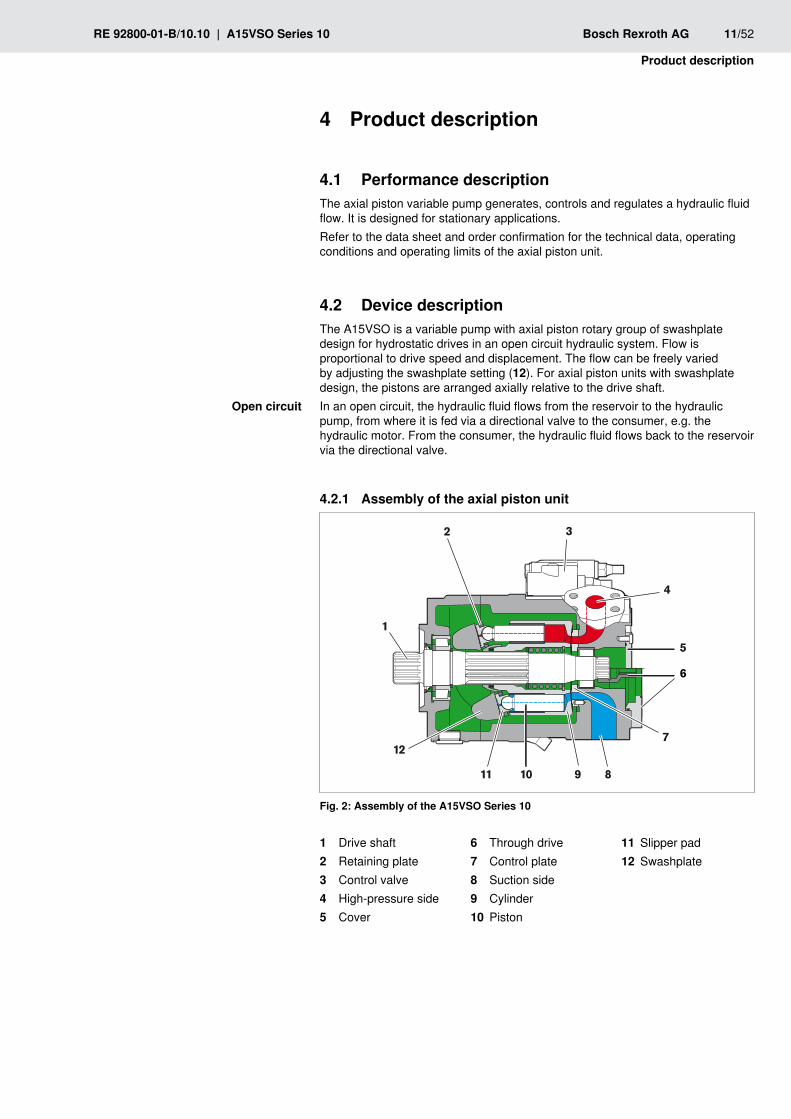
4.2 Device descriptionThe A15VSO is a variable pump with axial piston rotary group of swashplate design for hydrostatic drives in an open circuit hydraulic system. Flow is proportional to drive speed and displacement. The flow can be freely varied by adjusting the swashplate setting (12). For axial piston units with swashplate design, the pistons are arranged axially relative to the drive shaft.In an open circuit, the hydraulic fluid flows from the reservoir to the hydraulic pump, from where it is fed via a directional valve to the consumer, e.g. the hydraulic motor. From the consumer, the hydraulic fluid flows back to the reservoir via the directional valve.
4.2.1 Assembly of the axial piston unit
1
2
10
3
4
7
8911
12
5
6
Assembly of the A15VSO Series 10Fig. 2:
1 Drive shaft2 Retaining plate3 Control valve4 High-pressure side5 Cover
6 Through drive7 Control plate 8 Suction side9 Cylinder10 Piston
11 Slipper pad12 Swashplate
Open circuit
12/52 Bosch Rexroth AG A15VSO Series 10 | RE 92800-01-B/10.10
Product description
Functional description4.2.2 Torque and a rotational speed are applied to the drive shaft (1) by an engine. The cylinder (9) is picked up and turned by the splines of the drive shaft. With every revolution, the pistons (10) execute a stroke in the cylinder bores, the size of which depends on the pitch of the swashplate (12). The slipper pads (11) are held on with the pistons and guided along the glide surface of the swashplate by the retaining plate (2). The pitch of the swashplate moves each piston throughout a revolution through top and bottom dead center and back to the initial position. Here, fluid is fed into and out through two control slots in the control plate (7) according to the displacement. On the suction side, (8) fluid flows into the enlarging piston chamber. At the same time, on the high-pressure side (4) the fluid is pushed out of the cylinder chamber into the hydraulic system by the pistons.The swivel angle of the swashplate (12) is steplessly varied. Adjusting the swashplate swivel angle controls the piston stroke and, therefore, the displacement. The swivel angle is controlled hydraulically via the stroke piston (not illustrated). The swashplate is mounted in swivel bearings for easy motion, and it is kept in balance by the opposing piston (not illustrated). Increasing the swivel angle increases the displacement; reducing the angle results in a corresponding reduction in displacement.The swivel angle can be adjusted between zero and +100% in pump mode, depending on the controller version. With special controllers, motor mode is also possible with swivel up to -100%.
Various control devices are available depending on requirements. Information about this can be found in data sheet RE 92800.
The following warning notice applies to all axial piston units with the controllers/control units E. and H. as either basic or additional controllers.
The spring return in the control unit is not a safety device.The spool valve inside the control unit can get stuck in an undefined position by internal contamination (contaminated hydraulic fluid, abrasion or residual contamination from system components). As a result, the axial piston unit can no longer supply the flow specified by the operator.
Check whether your application requires that remedial measures be taken fon your machine in order to bring the driven consumer into a safe position (e. g. immediate stop).
Pump
Control
CAuTION!

RE 92800-01-B/10.10 | A15VSO Series 10 Bosch Rexroth AG 13/52
Product description
4.3 Product identificationThe axial piston unit can be identified from the name plate. The following example shows an A4VG A15VSO name plate:
7201
richtungDreh-
SN:
Made in Germany
12345678
xxxxxxxxxxxx
MNR: FD:
Rexroth A15VO280LRE2A0V/10MRVE4A41E
10W09
1
6
23
491011
12
578
13
14
A4VSO name plate A15VSOFig. 3:
Manufacturer1 Production date2 Internal plant designation3 Direction of rotation (viewed from 4 drive shaft) – here: clockwisePower setting (optional)5 Barcode6 Rotational speed7 Flow setting (optional)8
Pressure controller setting 9 (optional)Displacement10 Serial number11 Material number of the axial piston 12 unit
13 Ordering codeCustomer number14

14/52 Bosch Rexroth AG A15VSO Series 10 | RE 92800-01-B/10.10
Transport and storage
5 Transport and storage
Transporting the axial piston unit5.1
Risk of damage!Striking or impulsive forces could damage the axial piston unit.
Do not strike the coupling or drive shaft of the axial piston unit. fDo not set/place the axial piston unit on the drive shaft. fDo not strike sensitive fittings (e.g. sensors or valves). fDo not strike sealing areas (e.g. the suction port or through drive). fLeave the flange cover on the axial piston unit until shortly before the lines are fconnected.
Axial piston units can be transported with a forklift truck or with a lifting device.
Make certain that the forklift truck or lifting device has adequate lifting fcapacity.
Table 3: Dimensions and weightsSize 280Weight kg 143
Width mm The dimensions vary with the unit type. The values applicable for your axial piston unit can be found in the installation drawing (request if necessary).
Height mmDepth mm
Transporting with lifting device5.1.1 For transporting, the axial piston unit can be connected to a lifting device via a ring screw in the case or in the drive shaft. Alternatively, it can also be transported with a lifting strap.
Only use the lifting strap if you are unable to achieve the required installation position by transporting with the ring screw.
f For all threaded holes, use a threaded plug from the same system of units and of the correct size.Screw a ring screw fully into the thread in the case. fMake sure that each ring screw can bear the total weight of the axial piston funit plus approx. 20%.
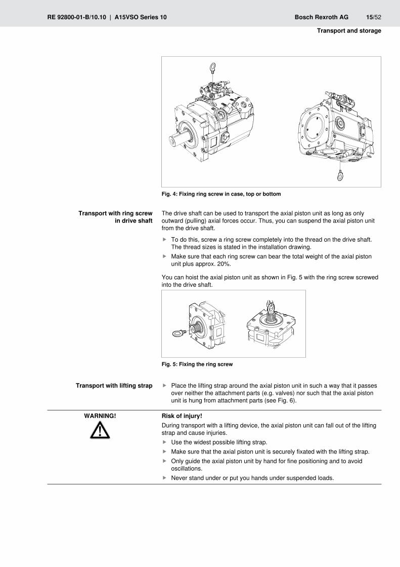
You can hoist the axial piston unit as shown in Fig. 4 with the ring screw screwed into the case.
CAuTION!
Dimensions and weights
Transport with ring screw in case
RE 92800-01-B/10.10 | A15VSO Series 10 Bosch Rexroth AG 15/52
Transport and storage
Fixing ring screw in case, top or bottomFig. 4:
The drive shaft can be used to transport the axial piston unit as long as only outward (pulling) axial forces occur. Thus, you can suspend the axial piston unit from the drive shaft.
To do this, screw a ring screw completely into the thread on the drive shaft. fThe thread sizes is stated in the installation drawing.Make sure that each ring screw can bear the total weight of the axial piston funit plus approx. 20%.
You can hoist the axial piston unit as shown in Fig. 5 with the ring screw screwed into the drive shaft.
Fixing the ring screwFig. 5:
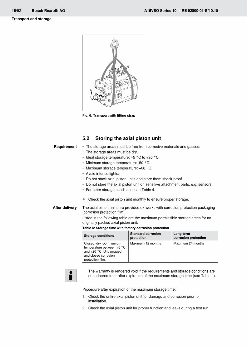
f Place the lifting strap around the axial piston unit in such a way that it passes over neither the attachment parts (e.g. valves) nor such that the axial piston unit is hung from attachment parts (see Fig. 6).
Risk of injury!During transport with a lifting device, the axial piston unit can fall out of the lifting strap and cause injuries.
Use the widest possible lifting strap. fMake sure that the axial piston unit is securely fixated with the lifting strap. fOnly guide the axial piston unit by hand for fine positioning and to avoid foscillations.Never stand under or put you hands under suspended loads. f
Transport with ring screw in drive shaft
Transport with lifting strap
wARNING!
16/52 Bosch Rexroth AG A15VSO Series 10 | RE 92800-01-B/10.10
Transport and storage
Transport with lifting strapFig. 6:
Storing the axial piston unit5.2 • The storage areas must be free from corrosive materials and gasses.
The storage areas must be dry. •Ideal storage temperature: +5 °C to +20 °C •Minimum storage temperature: -50 °C. •Maximum storage temperature: +60 °C. •Avoid intense lights. •Do not stack axial piston units and store them shock-proof. •Do not store the axial piston unit on sensitive attachment parts, e.g. sensors. •For other storage conditions, see Table 4. •
Check the axial piston unit monthly to ensure proper storage. f
The axial piston units are provided ex-works with corrosion protection packaging (corrosion protection film).Listed in the following table are the maximum permissible storage times for an originally packed axial piston unit.Table 4: Storage time with factory corrosion protection
Storage conditions Standard corrosion protection
long-term corrosion protection
Closed, dry room, uniform temperature between +5 °C and +20 °C. Undamaged and closed corrosion protection film.
Maximum 12 months Maximum 24 months
The warranty is rendered void if the requirements and storage conditions are not adhered to or after expiration of the maximum storage time (see Table 4).
Procedure after expiration of the maximum storage time:
Check the entire axial piston unit for damage and corrosion prior to 1. installation.
Check the axial piston unit for proper function and leaks during a test run.2.
Requirement
After delivery

RE 92800-01-B/10.10 | A15VSO Series 10 Bosch Rexroth AG 17/52
Transport and storage
If the storage time exceeds 24 months, the shaft seal must be replaced.3.
After expiry of the maximum storage time, we recommend that you have the axial piston unit inspected by your responsible Rexroth Service partner.
In the event of questions regarding repair and spare parts, contact your responsible Rexroth Service partner or the service department of the manufacture's plant for the axial piston unit, see chapter "9.5 Spare parts" for further information.If a dismounted axial piston unit is to be stored, it must be preserved against corrosion for the duration of the storage.
The following instructions only refer to axial piston units which are operated with a mineral-oil based hydraulic fluid. Other hydraulic fluids require preservation methods that are specifically designed for them. In such a case, consult with Rexroth Service (see chapter "9.5 Spare parts" for address).
Rexroth recommends the following procedure:
Clean the axial piston unit, see chapter "9.1 Cleaning and care".1.
Completely empty the axial piston unit.2.
For storage time up to 12 months: Moisten the inside of the axial piston unit 3. with mineral oil and fill with approx. 100 ml mineral oil. For storage time up to 24 months: Filling the axial piston unit with corrosion protection VCI 329 (20 ml). Filling is done through the case drain port "T1", "T2" or "T3", see chapter "6.4 Installing axial piston unit", Fig. 13.
Seal all ports airproof.4.
Moisten the unpainted areas of the axial piston unit with mineral oil or with a 5. suitable, easily removable corrosion protection agent, e.g. acid-free grease.
Package the axial piston unit airproof together with desiccant in corrosion 6. protection film.
Store the axial piston unit so that it is protected against jolts. See 7. "Requirement" in this chapter for further conditions.
After removal
18/52 Bosch Rexroth AG A15VSO Series 10 | RE 92800-01-B/10.10
Installation
6 InstallationPrior to installation, the following documents must be available:
Installation drawing for the axial piston unit (available from Rexroth) •Hydraulic circuit diagram for the axial piston unit (in the installation drawing) •Hydraulic circuit diagram for the system (available from the system •manufacturer)Order confirmation (contains the preset data of the axial piston unit) •Data sheet for the axial piston unit (contains the technical data) •
6.1 unpackingThe axial piston unit is delivered in a corrosion protection film made of polyethylene material (PE).
Dispose of the packaging according to the national regulations of your country. f
Risk of parts falling outIf the packaging is not opened correctly, parts may fall out and damage the parts or even result in injury.
Place the packaging on a flat and solid underground. fOnly open the packaging from the top. f
6.2 Installation conditionsThe installation location and position of the axial piston unit essentially •determine the procedures during installation and commissioning (such as when filling and air bleeding the axial piston unit).Correct filling and air bleeding is necessary to prevent damage to the axial •piston unit and to maintain correct function.Note that you can expect certain installation positions to affect the control •device. Because of gravity, dead weight and case pressure, minor characteristic displacements and actuating time changes may occur.
Observe all limits specified in the data sheet, e.g. temperature, viscosity fhydraulic fluid purity and direction of rotation.Make certain that the axial piston unit is air bled and filled with hydraulic fluid fduring commissioning and operation. This is also to be observed following relatively long standstill periods as the axial piston unit may empty via the hydraulic lines.The case drain fluid in the case interior must be directed to the reservoir via fthe highest case drain port. Use the line size which is appropriate for the port.A check valve in the case drain line (cracking pressure 0.5 bar) can prevent fthe system emptying through the case drain line. Please not the correct flow direction.To achieve favorable noise values, decouple all connecting lines from all fvibration-capable components (e.g. reservoir) using elastic elements.
CAuTION!

RE 92800-01-B/10.10 | A15VSO Series 10 Bosch Rexroth AG 19/52
Installation
Make certain that the suction line, case drain fluid, and return line flow into the freservoir below the minimum fluid level in all operating conditions. This will prevent air from being drawn in, which could result in the formation of foam.
S
1 230
0 12
-1
-0.20.8 abs.
21
Suction pressureFig. 7:
Absolute pressure gauge1 Standard pressure gauge2
Make certain that a minimum suction pressure of 0.8 bar absolute is present fat port "S" (0.5 bar absolute for cold start) during operation in all installation positions and installation locations for the axial piston pump, see Fig. 7. See data sheet for additional values.Suction conditions are improved with below-reservoir installation and inside-reservoir installation.
Absolute cleanliness is required. The axial piston unit must be installed in a fclean condition. Contamination of the hydraulic fluid can have a considerable impact on the function and service life of the axial piston unit.Do not use any cotton waste or linty cloths for cleaning. fUse suitable liquid detergents to remove lubricants and other difficult-to- fremove contamination. Detergents must not penetrate the hydraulic system.
Risk of damage due to lack of lubrication!Sufficient lubrication must be guaranteed to prevent damage to the axial piston unit.
During installation, make sure that the motor case is completely filled with fhydraulic fluid during commissioning and during operation with the installation position "drive shaft upwards" (e.g. no air intrusions).Make certain that the suction line is always filled with hydraulic fluid during fcommissioning and operation.
CAuTION!

20/52 Bosch Rexroth AG A15VSO Series 10 | RE 92800-01-B/10.10
Installation
6.3 Installation positionThe following installation positions are permissible. The shown piping layout illustrates the basic layout.
6.3.1 Below-reservoir installation (standard)Below-reservoir installation is when the axial piston unit is installed outside of the reservoir below the minimum fluid level.
Recommended installation positions: 1 and 2.
ht min
hmin
T1
T2
S
S
ht minhmin
SB
SB
amin
amin
1 2
T2
T3
T1
ht minhmin
T2 S
SB
amin
3
T1
T3
T3
Below-reservoir installation with installation positions 1–3Fig. 8:
T1, T2 Highest case drain port ht min Minimum necessary immersion depth (200 mm)
S Suction port hmin Minimum necessary spacing from suction port to reservoir base (100 mm)
SB Baffle (baffle plate) amin When designing the reservoir, ensure adequate distance between the suction line and the case drain line. This prevents the heated, return flow from being drawn directly back into the suction line.
Below-reservoir installationTable 5: Installation position Air bleeding Filling1 (drive shaft, horizontal) T1 S + T1
2 (drive shaft, horizontal) T2 S + T2
3 (drive shaft, vertical) T2 S + T2

RE 92800-01-B/10.10 | A15VSO Series 10 Bosch Rexroth AG 21/52
Installation
Inside-reservoir installation6.3.2 Inside-reservoir installation is when the axial piston unit is installed in the reservoir below the minimum fluid level. The axial piston unit is completely below the hydraulic fluid. If the minimum fluid level is equal to or below the upper edge of the pump, see chapter "6.3.3 Above-reservoir installation".
Risk of damage during inside-reservoir installation!To prevent damages to the axial piston unit, all plastic parts (e.g. protective caps, covers) must be removed prior to installation in the reservoir.
Remove all plastic parts before installing the axial piston unit in the reservoir. fMake certain that no pieces of these parts remain in the reservoir.Remove the flange cover from the suction port " f S" and open at least one T port.Axial piston units with electrical component must not be installed below the fhydraulic fluid level.
Our advice is to fit a suction pipe to the suction port "S" and to fit a pipe to case drain port "T1", "T2" or "T3". In such cases, the other case drain ports must be plugged. The case of the axial piston unit should be filled before fitting the piping and filling the reservoir with hydraulic fluid.
S
hminamin
ht min
54
T2
hmin
ht min
amin
T1
T1
T2
T3
T3
6
S
hminamin
ht min
T2
T1
T3
SB SB
SB
Inside-reservoir installation with installation positions 4–6Fig. 9:
T1, T2 Highest case drain port hmin Minimum necessary spacing from suction port to reservoir base (100 mm)
S Suction port amin When designing the reservoir, ensure adequate distance between the suction line and the case drain line. This prevents the heated, return flow from being drawn directly back into the suction line.
SB Baffle (baffle plate)
ht min Minimum necessary immersion depth (200 mm)
CAuTION!

22/52 Bosch Rexroth AG A15VSO Series 10 | RE 92800-01-B/10.10
Installation
Inside-reservoir installationTable 6: Installation position Air bleeding Filling4 (drive shaft, horizontal) via the highest open
port T1
automatically via the open port T1 due to position below hydraulic fluid level
5 (drive shaft, horizontal) via the highest open port T2
automatically via the open port T2 due to position below hydraulic fluid level
6 (drive shaft, vertical) via the highest open port T2
automatically via the open port T2 due to position below hydraulic fluid level
6.3.3 Above-reservoir installationAbove-reservoir installation is when the axial piston unit is installed above the minimum fluid level of the reservoir.
Risk of damage due to lack of lubrication!Sufficient lubrication must be guaranteed to prevent damage to the axial piston unit.
During installation, make sure that the motor case is completely filled with fhydraulic fluid during commissioning and during operation with the installation position " drive shaft upwards" (e.g. no air inclusions).Check the hydraulic fluid level in the case interior regularly; if necessary, frecommission. With above-reservoir installation, the case interior may drain via the case drain line after longer standstill periods (air enters via the shaft seal ring) or via the service line (gap leakage). The bearings are thus insufficiently lubricated when the pump is recommissioned.Make certain that the suction line is always filled with hydraulic fluid during fcommissioning and operation.
Observe the maximum permissible suction height hS max = 800 mm. The permissible suction height hs is derived from the total pressure loss.
CAuTION!
RE 92800-01-B/10.10 | A15VSO Series 10 Bosch Rexroth AG 23/52
Installation
hS max
ht min
hmin
SB
SB
F
F
S
S
7 8
amin
amin
T2
hS max
ht min
hmin
SB
F
S
9
T1
amin
T1
T2
T3
T2
T3
T1
T3
hS max
ht min
hmin
0.5
bar
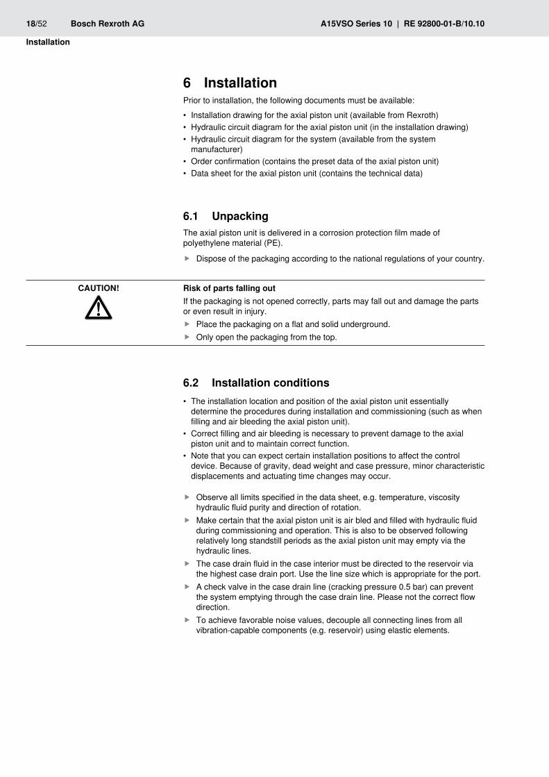
Above-reservoir installation with installation positions 7–9Fig. 10:
T1, T2 Highest case drain port hS max Maximum permissible suction height
F Air bleed and filling port ht min Minimum necessary immersion depth (200 mm)
S Suction port hmin Minimum necessary spacing from suction port to reservoir base (100 mm)
SB Baffle (baffle plate) amin When designing the reservoir, ensure adequate distance between the suction line and the case drain line. This prevents the heated, return flow from being drawn directly back into the suction line.
Above-reservoir installationTable 7: Installation position Air bleeding Filling7 (drive shaft, horizontal) F T1 (F)
8 (drive shaft, horizontal) F T2 (F)9 (drive shaft, vertical) F T2 (F)

24/52 Bosch Rexroth AG A15VSO Series 10 | RE 92800-01-B/10.10
Installation
Installing the axial piston unit6.4
Systems which are in operation pose a risk of injury!Working on operating systems poses a danger to life and limb. The work steps described in this chapter must only be performed on systems which are at a standstill. Before beginning work:
Ensure that the engine cannot be switched on. fEnsure that all power-transmitting components and connections (electric, fpneumatic, hydraulic) are switched off according to the manufacturer's instructions and are secured against being switched on again. If possible, remove the main fuse for the system.Ensure that the system is completely hydraulically relieved and depressurized. fPlease follow the system manufacturer's instructions.Only qualified personnel (see chapter "2.3 Personnel qualifications") are fauthorized to install the axial piston unit.
6.4.1 Preparation
Check the delivery contents for completeness and transport damages.1.
Compare the material number and designation (ordering code) with the details 2. in the order confirmation.
If the material number for the axial piston unit does not correspond to the one in the order confirmation, contact Rexroth Service for clarification, see chapter "9.5 Spare parts" for address.
Before installing, completely empty the axial piston unit to prevent mixing with 3. the hydraulic fluid used in the system.
Check the direction of rotation of the axial piston unit (on the name plate) and 4. make sure that this corresponds to the direction of rotation of the engine.
L
R
Fig. 11: Direction of rotation
l Counter-clockwise
R Clockwise
The direction of rotation as specified on the name plate determines the direction of rotation of the axial piston unit as viewed on the drive shaft. For information on the direction of rotation of the engine, please refer to the engine manufacturer's instruction manual.
DANGER!

RE 92800-01-B/10.10 | A15VSO Series 10 Bosch Rexroth AG 25/52
Installation
6.4.2 DimensionsThe installation drawing contains the dimensions for all connections and ports on the axial piston unit. Also observe the manuals provided by the manufacturers of the other components when selecting the required tools.
6.4.3 General instructionsDuring installation (and disassembly) of the axial piston unit, observe the following general instructions and handling instructions:
After a short operating time, toothed belts lose a major portion of their pre- •tension and thus cause speed variations and torsional vibrations. Torsional vibrations may cause leakages on the shaft seal ring or increased rotary angle accelerations of the rotary group of the driven axial piston unit. Particularly at risk are diesel drives with a small number of cylinders and low flywheel mass.V-belt drives without automatic tensioning device are also critical with regard to •speed variations and torsional vibrations. These can also lead to leakages on the shaft seal ring. An automatic tensioning device can lessen the speed variations and vibrations and thus avoid consequential damage.When transferring the input or output drive of an axial piston unit with the aid of •a cardan shaft, vibrations may occur which may result in leakages on the shaft seal ring of the axial piston unit depending on the temperature and frequency.
When using toothed belts or v-belts to transfer the input or output drive, falways use an automatic tensioning device.Fix the axial piston unit so that the expected forces and torques can be ftransferred without any danger.The permissible axial and radial loading of the drive shaft, the permissible ftorsional vibrations, the optimum direction of load force, as well as the limit speeds can be found in the data sheet.Observe the permissible radial forces on the drive shaft when driving with fradial loading (belt drives). If necessary, the belt pulley must be separately mounted.
Risk of damage!Striking or impulsive forces could damage the axial piston unit.
Do not strike the coupling or drive shaft of the axial piston unit. fDo not set/place the axial piston unit on the drive shaft. fDo not strike sensitive fittings (e.g. sensors or valves). fDo not strike sealing areas (e.g. the suction port or through drive). f
How to install the axial piston unit depends on the connecting elements to the drive side. The following descriptions explain the installation of the axial piston unit:
with clutch •on a gearbox •
wARNING!
26/52 Bosch Rexroth AG A15VSO Series 10 | RE 92800-01-B/10.10
Installation
6.4.4 Installation with clutchHow to install the axial piston unit with a coupling is described in detail in the following:
Install the specified coupling half onto the drive shaft of the axial piston unit 1. according to the instructions of the coupling manufacturer.
The drive shaft of the axial piston unit is equipped with a threaded bore. Use this threaded bore to pull the coupling element onto the drive shaft. Refer to the installation drawing for the dimensions of the threaded bore.
Make certain that the installation location is clean and free from dirt and 2. contaminants.
Clamp the coupling hub onto the drive shaft or ensure permanent lubrication 3. of the drive shaft. This prevents the formation of frictional corrosion and the associated wear.
Transport the axial piston unit to the installation location.4.
Install the coupling onto the input according to the instructions of the coupling 5. manufacturer.
The axial piston unit must not be tightened down until the coupling has been correctly installed.
Fix the axial piston unit at the installation location.6.
If necessary, details on the required tools and tightening torques for the fixing 7. screws are available from the machine or system manufacturer.
For bell housing installation, check the coupling axial play through the bell –window according to the manufacturer's instructions.For flange installation, align the support for the axial piston unit with the –input.
When using flexible couplings, check that the input is free of resonance after 8. completing the installation.
6.4.5 Installation on a gearboxHow to install the axial piston unit on a gearbox is described in detail in the following:After installing on a gearbox, the axial piston unit is covered and is difficult to access:
Therefore, before installing, make sure that the centering spigot centers the faxial piston unit (observe tolerances) and that no impermissible axial or radial forces act on the drive shaft of the axial piston unit (installation length).Protect the spline of the drive shaft from frictional corrosion by providing fpermanent lubrication.
6.4.6 Completing installation
Remove any mounted transport screws.1.
Remove the transport protection. 2. The axial piston unit was delivered with protective covers and plastic plugs or locking screws. These must be removed before connecting. Use appropriate tools.

RE 92800-01-B/10.10 | A15VSO Series 10 Bosch Rexroth AG 27/52
Installation
Make certain that the sealing and functional surfaces are not damaged.3.
Ports which are intended for connecting lines are provided with plastic plugs or locking screws which serve as transport protection. All ports needed for the function must be connected (see Table 8). Failure to comply with this could lead to malfunctions or damage. If no connection is made, these ports must be plugged with a suitable metal locking screw since the plastic plugs are not pressure-proof.
Risk of damage to persons and property!Operating the axial piston unit with plastic plugs can result in injuries or damage to the axial piston unit.
Before commissioning, remove all plastic plugs and replace them with fsuitable, pressure-proof, metal locking screws.
1
1
2
43
Fig. 12: Removing transport protection
Steel flange cover1 Locking screw in ports 2 T1, T2 and T3
Plastic plug for control ports3
For version with through drive, 4 metallic flange cover and fixing screws
The adjusting screws are protected against unauthorized resetting by means of protective caps. Removal of the protective caps will void the warranty. If you need to modify the setting, please contact your responsible Rexroth Service (address as to chapter "9.5 Spare parts").
For versions with through drive, install the auxiliary pump according to the 4. pump manufacturer's manual.
CAuTION!

28/52 Bosch Rexroth AG A15VSO Series 10 | RE 92800-01-B/10.10
Installation
Hydraulically connecting the axial piston unit6.4.7 The machine or system manufacturer is responsible for dimensioning the lines. The axial piston unit must be connected to the rest of the hydraulic system in accordance with the hydraulic circuit diagram of the machine or system manufacturer.
Damage to the axial piston unit!Hydraulic lines and hoses that are installed under mechanical stress generate additional mechanical forces during operation, which will reduce the service life of the axial piston unit and the entire machine or system.
Install hydraulic lines and hoses without mechanical stress. f
Risk of damage!Generally, a minimum permissible suction pressure at port "S" is specified for axial piston pumps in all installation positions. If the pressure at port "S" drops below the specified values, damage may occur which may lead to the axial piston pump being damaged beyond repair.
Make sure that the necessary suction pressure is not undercut. This is finfluenced by:
the piping (e.g. suction cross-section, pipe diameter, length of suction line) –the position of the reservoir –the viscosity of the hydraulic fluid –a filter cartridge or check valve in the suction line, if these are fitted –(regularly check the level of soiling of the filter cartridge)
Only connect suitable hydraulic lines to the service and function ports.
wear and malfunctionsThe cleanliness of the hydraulic fluid has a considerable impact on the cleanliness and service life of the hydraulic system. Any contamination of the hydraulic fluid leads to wear and malfunctions. In particular, contaminants, such as welding beads or metal cuttings in the hydraulic lines, may damage the axial piston unit.
Absolute cleanliness is required. fThe axial piston unit must be installed in a clean condition. fMake certain that all ports, hydraulic lines and add-on units (e.g. measuring fequipment) are clean.Make certain that no contaminants enter when sealing the ports. fMake certain that no detergents enter the hydraulic system. fDo not use any cotton waste or linty cloths for cleaning. fDo not use hemp as a sealant under any circumstances. f
For inside-reservoir installation, the case of the axial piston unit should be filled before fitting the piping and filling the reservoir with hydraulic fluid.
CAuTION!
CAuTION!
CAuTION!

RE 92800-01-B/10.10 | A15VSO Series 10 Bosch Rexroth AG 29/52
Installation
Observe the following notes when routing the suction, pressure and case drain lines.
Make certain that the suction line (pipe or hose) is as short and straight as fpossible.The line cross section of the suction line is to be sized so that the minimum fpermissible pressure at the suction port and the maximum permissible pressure are not exceeded.Be certain that the design of all junctions is air tight and that the pressure fcapability of all hoses meet specifications, also with respect to the external air pressure.With the pressure lines, make certain that the pipes, hoses and connecting felements are approved for the operating pressure range.Always route the case drain lines so that the housing is constantly filled fwith hydraulic fluid and to ensure that no air gets through the shaft seal ring even during extended standstill periods. The case internal pressure must not exceed the maximum values listed for the axial piston unit in the data sheet under any operating conditions. The case drain line in the reservoir must end up below the minimum fluid level under all conditions (see chapter "6.3 Installation position").
The ports and fixing threads are designed for the maximum pressure specified in the data sheet. The machine or system manufacturer must ensure that the connecting elements and lines correspond to the specified application conditions (pressure, flow, hydraulic fluid, temperature) with the necessary safety factors.
To connect the axial piston unit to the hydraulic system:
Remove the locking screws at the ports at which the connections are to be 1. made according to the hydraulic circuit diagram.
Only use clean hydraulic lines or rinse out the hydraulic system with a 2. flushing unit before commissioning. Follow the instructions of the flushing unit manufacturer.
Connect the lines according to the hydraulic circuit diagram. 3. Either pipes or hoses must be connected to all ports according to the installation drawing and machine or system circuit diagram or the ports plugged using suitable locking screws.
The installation drawing contains the dimensions for all connections and ports on the axial piston unit. Also observe the manuals provided by the manufacturers of the other hydraulic components when selecting the required tools.
Make certain that the union nuts on the fittings and flanges are tightened 4. correctly (observe the manufacturer's tightening torques!). Mark all checked fittings using e.g. a permanent marker pen.
Make certain that the pipes and hose lines and every combination of 5. connecting piece, coupling or connecting point with hoses or pipes have been inspected by a technically qualified person for safe working condition.
Notes on routing the lines
Procedure
30/52 Bosch Rexroth AG A15VSO Series 10 | RE 92800-01-B/10.10
Installation
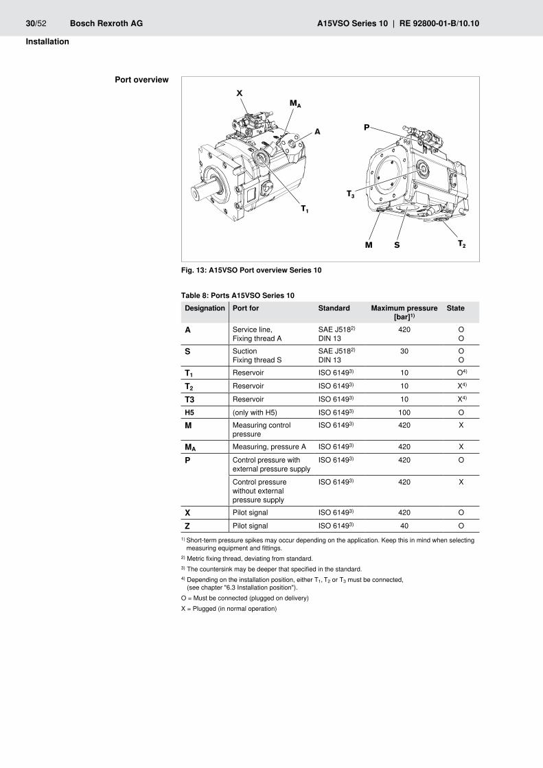
A15VSO Port overview Series 10Fig. 13:
Ports A15VSO Series 10Table 8: Designation Port for Standard Maximum pressure
[bar]1)State
A Service line, Fixing thread A
SAE J5182) DIN 13
420 OO
S SuctionFixing thread S
SAE J5182) DIN 13
30 OO
T1 Reservoir ISO 61493) 10 O4)
T2 Reservoir ISO 61493) 10 X4)
T3 Reservoir ISO 61493) 10 X4)
H5 (only with H5) ISO 61493) 100 O
M Measuring control pressure
ISO 61493) 420 X
MA Measuring, pressure A ISO 61493) 420 X
P Control pressure with external pressure supply
ISO 61493) 420 O
Control pressure without external pressure supply
ISO 61493) 420 X
X Pilot signal ISO 61493) 420 O
Z Pilot signal ISO 61493) 40 O1 ) Short-term pressure spikes may occur depending on the application. Keep this in mind when selecting
measuring equipment and fittings.2) Metric fixing thread, deviating from standard.3) The countersink may be deeper that specified in the standard.4) Depending on the installation position, either T1, T2 or T3 must be connected,
(see chapter "6.3 Installation position").O = Must be connected (plugged on delivery)X = Plugged (in normal operation)
Port overview
A
T1
T3
P
S T2M
MA
X

RE 92800-01-B/10.10 | A15VSO Series 10 Bosch Rexroth AG 31/52
Installation
The following tightening torques apply:
Threaded hole of the axial piston unit: •The maximum permissible tightening torques MG max are maximum values of the threaded holes and must not be exceeded. For values, see the following table.Fittings: •Observe the manufacturer's instruction regarding the tightening torques of the used fittings.Fixing screws: •For fixing screws according to DIN 13/ISO 68, we recommend checking the tightening torque in individual cases as per VDI 2230.Locking screws: •For the metallic locking screws supplied with the axial piston unit, the required tightening torques of locking screws MV apply. For values, see the following table.
Tightening torques of the threaded holes and locking screwsTable 9:
Ports Maximum permissible tightening torque of the threaded holes MG max
Required tightening torque of the locking screws MV
wAF hexagon socket for the locking screwsStandard Thread size
ISO 6149 M14 x 1.5 80 Nm 45 Nm 6 mmM42 x 2 580 Nm 330 Nm 22 mm1)
1) Different from ISO 6149
The axial piston units are used in application areas with metric as well as with Imperial systems of units.Both the system of units and the size of threaded hole and threaded plug (e.g. locking screw) must match.Due to the limited options for visually detecting differences, there is a risk of mix-ups.
Risk of damage to persons and property!If a threaded plug which is of a different measurement system and size with respect to the threaded hole is pressurized, the threaded plug may loosen itself or even be ejected from the hole in a projectile-like manner. This can result in serious injury and damage to equipment. Hydraulic fluid can be discharged from this leakage point.
Use the drawings (installation drawing/data sheet) to determine the required fthreaded plug for each fitting.Make certain that there are no mix-ups when installing fittings, fixing screws fand locking screws.For all threaded holes, use a threaded plug from the same system of units and fof the correct size.
Electrically connecting the axial piston unit6.4.8 The machine or system manufacturer is responsible for the layout of the electric control.Electrically controlled axial piston units must be connected in accordance with the electric circuit diagram of the system manufacturer.
Tightening torques
Risk of mix-ups with threaded connections
wARNING!

32/52 Bosch Rexroth AG A15VSO Series 10 | RE 92800-01-B/10.10
Installation
For axial piston units with electric control or mounted sensors, note for example:
the permissible voltage range •the permissible current •the correct connections •the recommended electric control units. •
These parameters can be found in data sheet RE 92800.
Missing seals and connections lead to noncompliance with the protection class!Fluids and contaminants may penetrate and damage the product beyond repair.
Prior to installation, make sure that all seals and connectors f are tight.
Short circuit in event of penetrating hydraulic fluid!Fluid can penetrate the product and cause a short circuit.
Do not install electrically controlled axial piston units in a reservoir below the freservoir fluid level (inside-reservoir installation).
Switch off power supply to the relevant system component.1.
Electrically connect the axial piston unit (12 or 24V).2.
If necessary, you can change the position of the connector by turning the solenoid.To do this, proceed as follows:
Loosen the fixing nut (1. 1) of the solenoid. To do this, turn the fixing nut (1) one turn counter-clockwise.
Turn the solenoid body (2. 2) to the desired position.
Retighten the fixing nut. Tightening torque of the fixing nut: 5+1 Nm.3.
For further details and technical data, e.g. regarding the selection of a suitable mating connector, refer to data sheet RE 92800.On axial piston units with Hirschmann connector, the following tightening torques apply when securing line connectors:
Fixing screw M3 ( • 1):0.5 Union nut M16 x 1.5 ( • 2): 1.5–2.5 Nm
1
2
Tightening torque for HIRSCHMANN connectorFig. 14:
CAuTION!
CAuTION!
Changing plug position
2
1
Tightening torque for HIRSCHMANN connector

RE 92800-01-B/10.10 | A15VSO Series 10 Bosch Rexroth AG 33/52
Commissioning
7 Commissioning
Danger while working in the danger zone of a machine or system!It is not permissible to work in the danger zone of a machine or system.
The machine or system must only be commissioned if safe working is fensured.Pay attention to and rectify potential danger sources before commissioning fthe machine or system.Nobody may stand in the danger zone of the machine or system. fThe emergency stop button for the machine or system must be within the foperator's reach.Always follow the instructions of the machine or system manufacturer during fcommissioning.
Risk of damage to persons and property!Commissioning of the axial piston unit requires basic mechanical and hydraulic knowledge.
Only qualified personnel (see chapter "2.3 Personnel qualifications") are fauthorized to commission the axial piston unit.
Risk of toxication and injury!Contact with hydraulic fluids may damage your health (e.g. eye injuries, skin damage, toxication upon inhalation).
Always check the lines for wear and damage before each commissioning. fWhile performing these checks, wear safety gloves, safety glasses and fsuitable working clothes.If hydraulic fluid should, nevertheless, come into contact with your eyes or fpenetrate your skin, consult a doctor immediately.When working with hydraulic fluids, strictly observe the safety instructions fprovided by the hydraulic fluid manufacturer.
Fire hazard!Hydraulic fluid is easily flammable.
Keep open flames and ignition sources away from the axial piston unit. f
First 7.1 commissioning
Risk of damage to the product!Any contamination of the hydraulic fluid leads to wear and malfunctions. In particular, contaminants, such as welding beads or metal cuttings in the hydraulic lines, may damage the axial piston unit.
Ensure utmost cleanliness during commissioning. fMake sure that no contaminants may penetrate when sealing the gauge ports f .
wARNING!
CAuTION!
wARNING!
wARNING!
CAuTION!

34/52 Bosch Rexroth AG A15VSO Series 10 | RE 92800-01-B/10.10
Commissioning
Risk of damage to the product!If you commission the axial piston unit without or with insufficient hydraulic fluid, the axial piston unit could be damaged immediately, possibly beyond repair.
When commissioning or recommissioning a machine or system, make sure fthat the case interior and the suction and service lines of the axial piston unit are filled with hydraulic fluid and remain filled during operation.
When commissioning the axial piston unit, observe the basic safety instructions and intended use provided in chapter "2 General safety instructions".
Connect the pressure gauge to the measurement points provided for operating fpressure, case pressure and suction pressure to check the technical data when operating for the first time.
Filling the axial piston unit7.1.1 You will require an approved hydraulic fluid:The machine or system manufacturer can provide you with precise details on the hydraulic fluid. Details on minimum requirements for mineral-oil based hydraulic fluids, environmentally acceptable hydraulic fluids or HF hydraulic fluids for the axial piston unit are available in the Rexroth publications RE 90220, RE 90221 and RE 90223, respectively.To ensure the functional reliability of the axial piston unit, cleanliness level 20/18/15 according to at least ISO 4406 is necessary for the hydraulic fluid. At very high hydraulic fluid temperatures (+90 °C to maximum +115 °C), cleanliness level 19/17/14 according to at least ISO 4406 is necessary. For permissible temperatures, see the data sheet.
Risk of damage due to lack of lubrication!Sufficient lubrication must be guaranteed to prevent damage to the axial piston unit.
Make sure that the motor case is completely filled with hydraulic fluid during fcommissioning and during operation with the installation position " drive shaft upwards" (e.g. no air inclusions).Make certain that the suction line is always filled with hydraulic fluid during fcommissioning and operation.With above-reservoir installation, an axial piston pump must be moved to ffull swivel angle after no more than 3 seconds during commissioning and recommissioning. Make certain that the axial piston pump really does suck in hydraulic fluid and build up pressure.
The axial piston unit should be filled with a filling unit (10 µm filter grade). The axial piston unit must not be operated while it is being filled with the filling unit.
Danger of environmental contamination!The discharge or spillage of hydraulic fluid while filling the axial piston unit can lead to environmental pollution and contamination of the groundwater.
When filling and changing the hydraulic fluid, always place a drip tray under fthe axial piston unit.Observe the information in the safety data sheet for the hydraulic fluid and the fspecifications provided by the system manufacturer.
CAuTION!
CAuTION!
CAuTION!

RE 92800-01-B/10.10 | A15VSO Series 10 Bosch Rexroth AG 35/52
Commissioning
Fill and air bleed the axial piston unit via the appropriate ports, see chapter 1. "6.3 Installation position". The hydraulic lines of the system must also be filled.
Test the direction of rotation of the engine. To do this, rotate the engine briefly 2. at the lowest rotational speed (inching). Make sure that direction of rotation of the axial piston unit matches the parameters on the name plate, see also chapter "4.3 Product identification", Fig. 3: Name plate.
Operate the axial piston pump at a lower speed (starter speed for internal 3. combustion engines or inching operation for electric motors) until the pump system is completely filled and bled. To inspect, drain the hydraulic fluid at the case drain port and wait until it drains without bubbles.
Make certain that all ports are either piped up or plugged according to the 4. general circuit diagram.
If a shut-off valve is used in the suction and/or case drain line, make sure that 5. the axial piston unit is not operated with the shut-off valves closed.
Testing the hydraulic fluid supply7.1.2 The axial piston unit must always have a sufficient supply of hydraulic fluid. For this reason, the supply of hydraulic fluid must be ensured at the start of the commissioning process.When you test the hydraulic fluid supply, constantly monitor the noise development and check the hydraulic fluid level in the reservoir. If the axial piston unit becomes louder (cavitation) or the case drain fluid is discharged with bubbles, this is an indication that the axial piston unit is not being sufficiently supplied with hydraulic fluid.Notes on troubleshooting can be found in chapter "14 Troubleshooting".To test the hydraulic fluid supply:
Allow the engine to run at the lowest speed. The axial piston unit must be 1. operated without load. Pay attention to leakage and noise.
Check the axial piston unit’s case drain line during the test. The case drain 2. fluid should not contain any bubbles.
Increase the load and check whether the operating pressure rises as 3. expected.
Check the suction pressure at "4. S" of the axial piston pump at nominal speed and maximum flow. Refer to data sheet RE 92800 for the permissible value.
Check the case drain pressure at the connected port "5. T1", "T2" or "T3" at maximum pressure. Refer to data sheet RE 92800 for the permissible value.
36/52 Bosch Rexroth AG A15VSO Series 10 | RE 92800-01-B/10.10
Commissioning
7.1.3 Performing functional test
Risk of injury in case of incorrectly connected machine or system!Any change of the connections will lead to malfunctions (e.g. lift instead of lower) and thus represents a corresponding danger to persons and equipment.
When connecting hydraulic components, observe the specified piping faccording to the hydraulic circuit diagram of the machine or system manufacturer.
Once you have tested the hydraulic fluid supply, you must perform a functional test on the machine or system. The functional test should be performed according to the instructions of the machine or system manufacturer.The axial piston unit is checked for functional capability before delivery according to the technical data. During commissioning, it must be ensured that the axial piston unit was installed in accordance with the design of the machine or system.
In particular, check whether the axial piston unit builds up pressure after the fengine is started and that the case pressure does not rise to an impermissible level.If necessary, remove the pressure gauge and plug the ports so that they are fpressure-proof.
7.1.4 Performing flushing cycleIn order to remove foreign bodies from the system, Rexroth recommends a flushing cycle for the entire system.
The flushing cycle must be performed with an additional flushing unit. Follow the instructions of the flushing unit's manufacturer for the exact procedure during the flushing cycle. To avoid internal contamination, the axial piston unit must not be included in the flushing cycle.
7.2 Recommissioning after standstillDepending on the installation conditions and ambient conditions, changes may occur in the system which make recommissioning necessary.Among others, the following criteria may make recommissioning necessary:
Air in the hydraulic system •Water in the hydraulic system •Old hydraulic fluid •Other contamination •
Before recommissioning, proceed as described in chapter f"7.1 First commissioning".
wARNING!
RE 92800-01-B/10.10 | A15VSO Series 10 Bosch Rexroth AG 37/52
Commissioning
7.3 Running-in phaseThe bearings and sliding surfaces are subject to a running-in phase. The increased friction at the start of the running-in phase results in increased heat development which decreases with increasing operating hours. The volumetric and mechanical-hydraulic efficiency increases as well through the conclusion of the running-in phase of approx. 10 operating hours.
Risk of damage by insufficient viscosity!Increased temperature of the hydraulic fluid can cause the viscosity to move out of the permissible range.
Monitor the operating temperature during the running-in phase, e.g. by fmeasuring the case drain temperature at port T1, T2 or T3.Reduce the loading (pressure, rpm) of the axial piston unit if impermissible foperating temperatures and/or viscosities occur.
CAuTION!

38/52 Bosch Rexroth AG A15VSO Series 10 | RE 92800-01-B/10.10
Operation
8 OperationThe product is a component which requires no settings or changes during operation. For this reason, this chapter of the manual does not contain any information on adjustment options. Use the product only within the performance range provided in the technical data. The machine or system manufacturer is responsible for the proper project planning of the hydraulic system and its control.
RE 92800-01-B/10.10 | A15VSO Series 10 Bosch Rexroth AG 39/52
Maintenance and repair
9 Maintenance and repair
9.1 Cleaning and care
Damage to the surface caused by solvents and aggressive detergents!Aggressive detergents may damage the seals on the axial piston unit and cause them to age faster.
Never use solvents or aggressive detergents. f
Damage to the hydraulic system and the seals!A power washer's water pressure could damage the electronics and the seals of the axial piston unit.
Do not point the power washer at sensitive components, e.g. shaft seal ring, felectrical connections and electrical components.
For cleaning and care of the axial piston unit, observe the following:
Plug all openings with suitable protective caps/devices. fCheck whether all seals and plugs of the plug connections are securely fseated to ensure that no moisture can penetrate into the axial piston unit during cleaning.Use only water and, if necessary, a mild detergent to clean the axial piston funit.Remove coarse dirt from the outside of the machine and keep sensitive fcomponents such as solenoids, valves, indicators and sensors clean.
9.2 InspectionIn order to enable long and reliable operation of the axial piston unit, Rexroth recommends testing the hydraulic system and axial piston unit on a regular basis and documenting the following operating conditions:
Inspection scheduleTable 10: Task to be carried out IntervalHydraulic system Check level of hydraulic fluid in the reservoir. daily
Check the operating temperature (comparable load conditions) at the case drain port and in the reservoir.
weekly
Perform a hydraulic fluid analysis: viscosity, aging, contamination
yearly or every 2000 h (which ever occurs first)
Axial piston unit
Check axial piston unit for leakage. Early detection of hydraulic fluid loss can help identify and rectify faults on the machine or system. For this reason, Rexroth recommends that the axial piston unit and system always be kept in a clean condition.
daily
Check axial piston unit for noise development. daily
Check fasteners for tight seating. All fasteners have to be checked when the system is switched off, non-pressurized and cooled down.
monthly
CAuTION!
CAuTION!
40/52 Bosch Rexroth AG A15VSO Series 10 | RE 92800-01-B/10.10
Maintenance and repair
9.3 MaintenanceThe axial piston unit is low maintenance when used as intended.The service life of the axial piston unit is heavily dependent on the quality of the hydraulic fluid. For this reason, we recommend changing the hydraulic fluid at least once per year or every 2000 operating hours (which ever occurs first) or having it analyzed by the hydraulic fluid manufacturer or a laboratory to determine its suitability for further use.The service life of the axial piston unit is limited by the service life of the bearings fitted. The service life can be requested from the responsible Rexroth Service partner, see "9.5 Spare parts" for address. Based on these details, a maintenance period is to be determined by the system manufacturer for the replacement of the bearings and included in the maintenance schedule of the hydraulic system.
9.4 RepairRexroth offers a comprehensive range of services for the repair of Rexroth axial piston units.Repairs to the axial piston unit may only be performed by authorized, skilled and instructed personnel.
Only use genuine spare parts from Rexroth for repairing the Rexroth axial fpiston units.
Tested and pre-installed original Rexroth assembly groups allow for successful repair requiring only little time.
9.5 Spare parts
Personal injury and property damage due to faulty spare parts!Spare parts that do not meet the technical requirements specified by Rexroth may cause personal injury or property damage.
Use only original spare parts from Rexroth. f
The spare parts lists for axial piston units are order specific. When ordering spare parts, quote the material and serial number of the axial piston unit as well as the material numbers of the spare parts.Address all questions regarding spare parts to your responsible Rexroth Service partner or the service department of the manufacture's plant for the axial piston unit.
Bosch Rexroth AG An den Kelterwiesen 14 72160 Horb am Neckar, Germany Tel. +49 (0)74 51 - 92 0 Fax +49 (0)74 51 - 82 21 [email protected] For the addresses of foreign subsidiaries, please refer to www.boschrexroth.com/addresses
CAuTION!
RE 92800-01-B/10.10 | A15VSO Series 10 Bosch Rexroth AG 41/52
Decommissioning
10 DecommissioningThe axial piston unit is a component that does not require decommissioning. For this reason, this chapter of the manual does not contain any informationFor details about how to remove or replace your axial piston unit, please refer to chapter "11 Removal and replacement".
11 Removal and replacement
Required 11.1 toolsRemoval can be performed using standard tools. No special tools are necessary.
11.2 Preparing for removal
Risk of injuries due to remove under pressure and voltage!If you do not switch off the pressure and power supply before removing the product, you may get injured or the device or system components may be damaged.
Make certain that the relevant system components are not under pressure or fvoltage.
Decommission the entire system as described in the overall manual for the 1. machine or system.
Protect the complete system against being energized.2.
Relieve the hydraulic system according to the instructions of the machine or 3. system manufacturer.
11.3 Removing the axial piston unitProceed as follows to remove the axial piston unit:
Make sure that the hydraulic system is non-pressurized.1.
Check whether the axial piston unit has cooled down far enough so that it can 2. be removed without danger.
For below-reservoir installation, before removing the axial piston unit from the 3. complete system, seal the connection to the reservoir or drain the reservoir.
Place a drip tray under the axial piston unit to collect any hydraulic fluid that 4. may escape.
wARNING!
42/52 Bosch Rexroth AG A15VSO Series 10 | RE 92800-01-B/10.10
Removal and replacement
Danger of environmental contamination!If hydraulic fluid is spilled or escapes during removal of the axial piston unit, this can lead to environmental pollution and contamination of the ground water.
When draining the hydraulic fluid, always place a drip tray under the axial fpiston unit.Observe the information in the safety data sheet for the hydraulic fluid and the fspecifications provided by the system manufacturer.
Loosen the lines and collect the escaping hydraulic fluid in the container.5.
Remove the axial piston unit. Use an appropriate lifting device.6.
Completely empty the axial piston unit.7.
Plug all openings.8.
Preparing the components for storage or further 11.4 use
Proceed as described in section "5.2 Storing the axial piston unit". f
CAuTION!
RE 92800-01-B/10.10 | A15VSO Series 10 Bosch Rexroth AG 43/52
Disposal
12 DisposalObserve the following points when disposing of the axial piston unit:
Completely empty the axial piston unit.1.
Dispose of the hydraulic fluid according to the national regulations of your 2. country.
Remove the axial piston unit into its individual parts and properly recycle these 3. parts.
Separate parts by:4. Cast parts –Steel –Non-ferrous metal –Electronic waste –Plastic –Seals. –
12.1 Environmental protectionCareless disposal of the axial piston unit, the hydraulic fluid and the packaging material could lead to pollution of the environment.
Therefore, dispose of the axial piston unit, the hydraulic fluid and the fpackaging material in accordance with the currently applicable regulations in your country.Dispose of hydraulic fluid residues according to the applicable safety data fsheets for these hydraulic fluids.
Extension and 13 conversionDo not convert the axial piston unit. This also includes a modification of the adjusting screws.
The warranty from Rexroth only applies to the delivered configuration. In case of extensions or conversions, the warranty will become void.
Adjusting screws are protected against unauthorized resetting by means of protective caps. Removal of the protective caps will void the warranty. If you need to modify the setting, please contact your responsible Rexroth Service (address as to chapter "9.5 Spare parts").

44/52 Bosch Rexroth AG A15VSO Series 10 | RE 92800-01-B/10.10
Troubleshooting
14 TroubleshootingThe following table may assist you in troubleshooting. The table makes no claim for completeness.In practical use, problems which are not listed here may also occur.
How to proceed for troubleshooting14.1 Always act systematically and targeted, even under pressure of time. Random fand imprudent removal and readjustment of settings could result in the inability to ascertain the original error cause.First obtain a general overview of how your product works in conjunction with fthe entire system.Try to determine whether the product worked properly in conjunction with the fentire system before the error occurred.Try to determine any changes of the entire system in which the product is fintegrated.
Were there any changes to the product's application conditions or operating –range?Were there any changes (conversions) or repairs on the complete system –(machine / system, electrics, control) or on the product? If yes, which?Was the product or machine operated as intended? –How did the malfunction appear? –
Try to get a clear idea of the error cause. Directly ask the (machine) operator. fIf you cannot rectify the error, contact one of the contact addresses which can fbe found under: www.boschrexroth.com/addresses.
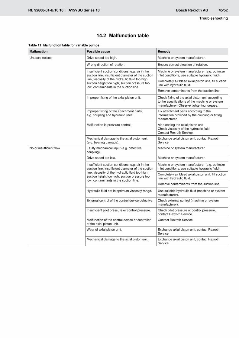
RE 92800-01-B/10.10 | A15VSO Series 10 Bosch Rexroth AG 45/52
Troubleshooting
14.2 Malfunction table
Malfunction table for variable pumpsTable 11:
Malfunction Possible cause Remedy
Unusual noises Drive speed too high. Machine or system manufacturer.
Wrong direction of rotation. Ensure correct direction of rotation.
Insufficient suction conditions, e.g. air in the suction line, insufficient diameter of the suction line, viscosity of the hydraulic fluid too high, suction height too high, suction pressure too low, contaminants in the suction line.
Machine or system manufacturer (e.g. optimize inlet conditions, use suitable hydraulic fluid).
Completely air bleed axial piston unit, fill suction line with hydraulic fluid.
Remove contaminants from the suction line.
Improper fixing of the axial piston unit. Check fixing of the axial piston unit according to the specifications of the machine or system manufacturer. Observe tightening torques.
Improper fixing of the attachment parts, e.g. coupling and hydraulic lines.
Fix attachment parts according to the information provided by the coupling or fitting manufacturer.
Malfunction in pressure control. Air bleeding the axial piston unitCheck viscosity of the hydraulic fluidContact Rexroth Service.
Mechanical damage to the axial piston unit (e.g. bearing damage).
Exchange axial piston unit, contact Rexroth Service.
No or insufficient flow Faulty mechanical input (e.g. defective coupling).
Machine or system manufacturer.
Drive speed too low. Machine or system manufacturer.
Insufficient suction conditions, e.g. air in the suction line, insufficient diameter of the suction line, viscosity of the hydraulic fluid too high, suction height too high, suction pressure too low, contaminants in the suction line.
Machine or system manufacturer (e.g. optimize inlet conditions, use suitable hydraulic fluid).
Completely air bleed axial piston unit, fill suction line with hydraulic fluid.
Remove contaminants from the suction line.
Hydraulic fluid not in optimum viscosity range. Use suitable hydraulic fluid (machine or system manufacturer).
External control of the control device defective. Check external control (machine or system manufacturer).
Insufficient pilot pressure or control pressure. Check pilot pressure or control pressure, contact Rexroth Service.
Malfunction of the control device or controller of the axial piston unit.
Contact Rexroth Service.
Wear of axial piston unit. Exchange axial piston unit, contact Rexroth Service.
Mechanical damage to the axial piston unit. Exchange axial piston unit, contact Rexroth Service.
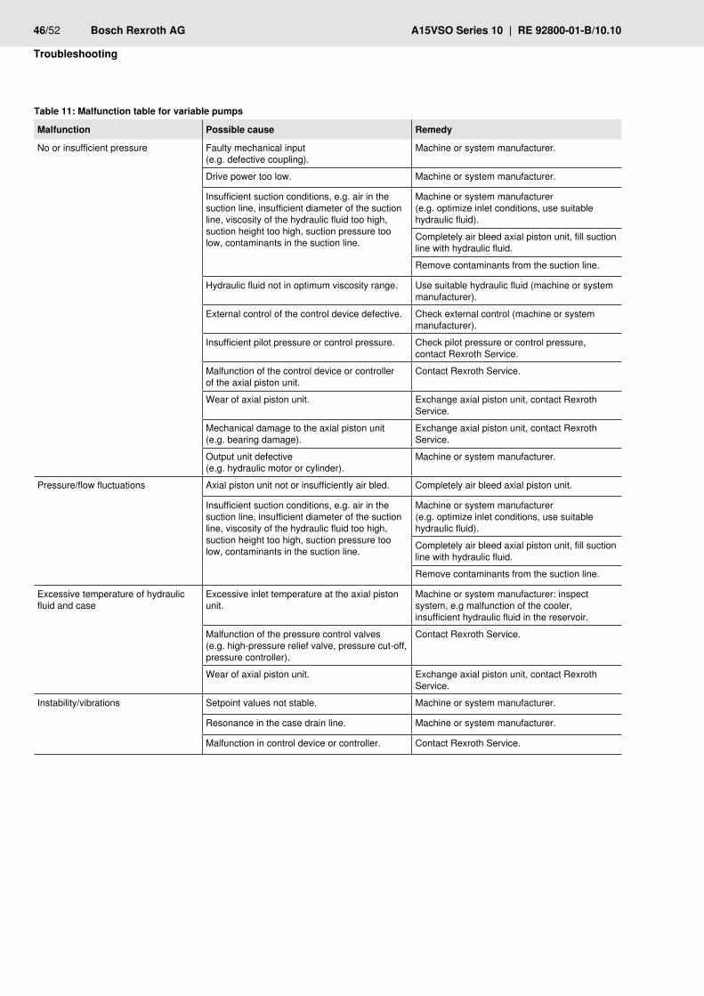
46/52 Bosch Rexroth AG A15VSO Series 10 | RE 92800-01-B/10.10
Troubleshooting
Malfunction table for variable pumpsTable 11:
Malfunction Possible cause Remedy
No or insufficient pressure Faulty mechanical input (e.g. defective coupling).
Machine or system manufacturer.
Drive power too low. Machine or system manufacturer.
Insufficient suction conditions, e.g. air in the suction line, insufficient diameter of the suction line, viscosity of the hydraulic fluid too high, suction height too high, suction pressure too low, contaminants in the suction line.
Machine or system manufacturer (e.g. optimize inlet conditions, use suitable hydraulic fluid).
Completely air bleed axial piston unit, fill suction line with hydraulic fluid.
Remove contaminants from the suction line.
Hydraulic fluid not in optimum viscosity range. Use suitable hydraulic fluid (machine or system manufacturer).
External control of the control device defective. Check external control (machine or system manufacturer).
Insufficient pilot pressure or control pressure. Check pilot pressure or control pressure, contact Rexroth Service.
Malfunction of the control device or controller of the axial piston unit.
Contact Rexroth Service.
Wear of axial piston unit. Exchange axial piston unit, contact Rexroth Service.
Mechanical damage to the axial piston unit (e.g. bearing damage).
Exchange axial piston unit, contact Rexroth Service.
Output unit defective (e.g. hydraulic motor or cylinder).
Machine or system manufacturer.
Pressure/flow fluctuations Axial piston unit not or insufficiently air bled. Completely air bleed axial piston unit.
Insufficient suction conditions, e.g. air in the suction line, insufficient diameter of the suction line, viscosity of the hydraulic fluid too high, suction height too high, suction pressure too low, contaminants in the suction line.
Machine or system manufacturer (e.g. optimize inlet conditions, use suitable hydraulic fluid).
Completely air bleed axial piston unit, fill suction line with hydraulic fluid.
Remove contaminants from the suction line.
Excessive temperature of hydraulic fluid and case
Excessive inlet temperature at the axial piston unit.
Machine or system manufacturer: inspect system, e.g malfunction of the cooler, insufficient hydraulic fluid in the reservoir.
Malfunction of the pressure control valves (e.g. high-pressure relief valve, pressure cut-off, pressure controller).
Contact Rexroth Service.
Wear of axial piston unit. Exchange axial piston unit, contact Rexroth Service.
Instability/vibrations Setpoint values not stable. Machine or system manufacturer.
Resonance in the case drain line. Machine or system manufacturer.
Malfunction in control device or controller. Contact Rexroth Service.
RE 92800-01-B/10.10 | A15VSO Series 10 Bosch Rexroth AG 47/52
Technical data
15 Technical dataThe technical data of your axial piston unit can be found in data sheet RE 92800.The data sheets can be found on the internet underwww.boschrexroth.com/axial-piston-pumps
The preset technical data of your axial piston unit can be found in the order confirmation.
Appendix16
16.1 Address directory For the addresses of foreign subsidiaries, please refer to www.boschrexroth.com/addresses

48/52 Bosch Rexroth AG A15VSO Series 10 | RE 92800-01-B/10.10
Alphabetical index
AAbbreviations 5Above-reservoir installation 22Address directory 47Assembly 11
BBelow-reservoir installation 20
CCare 39Caution 8Changing solenoid position 32Cleaning 39Commissioning 33
First 33Connecting
Electrical 31Hydraulic 28
Control plate 11Control valve 11Conversion 43Corrosion protection 16Cover 11Cylinder 11
DDanger 8Decommissioning 41Delivery contents 10Device description 11Dimensions 14, 25Direction of rotation 24Drive shaft 11
EEnvironmental protection 43
FFilling 34Flushing cycle 36Forklift truck 14Functional description
Control 12Open circuit 11Pump 12
Functional test 36
GGeneral instructions 25
HHigh-pressure side 11Hydraulic fluid 34
IIdentification 13Inspection 39Installation 18, 24
Completing 26General instructions 25On a gearbox 26Preparation 24With clutch 26
Installation conditions 18Installation position 20
Above-reservoir installation 22Below-reservoir installation 20
InstructionsGeneral 8, 25
lLifting device 14Lifting strap 15
MMaintenance 39, 40Malfunction table 45
NName plate 13
OObligations
of the operator 9Operation 38Ordering code 13
PPerformance description 11Piston 11Port overview 30Pressure side 11Product description 11
QQualifications
Personnel 7
Alphabetical index17

RE 92800-01-B/10.10 | A15VSO Series 10 Bosch Rexroth AG 49/52
Alphabetical index
RRecommissioning
After standstill 36Related documents 4Removal 41
Performing 41Preparing 41
Repair 40Replacement 41Retaining plate 11Ring screw 14, 15Running-in phase 37
SSafety instructions 6, 7Slipper pad 11Spare parts 40Storage 14Storage time 16Storing 16Suction side 11Swashplate 11
TTechnical data 47Through drive 11Tightening torques 31Tools 41Transport 14
With lifting device 15With ring screw 14, 15
Transporting 14Transport protection 27Troubleshooting 44
uUnpacking 18Use
Improper 6Intended 6
wWarning 8Warranty 8, 16, 27, 34, 43Waste disposal 43Weights 14

50/52 Bosch Rexroth AG A15VSO Series 10 | RE 92800-01-B/10.10

RE 92800-01-B/10.10 | A15VSO Series 10 Bosch Rexroth AG 51/52
Bosch Rexroth AGHydraulicsAxial piston unitsAn den Kelterwiesen 1472160 Horb a.N., GermanyTel. +49 (0) 74 51 92-0Fax +49 (0) 74 51 82 [email protected]/axial-piston-pumps
Printed in GermanyRE 92800-01-B/10.10