A1120/40 Programmable Electronic Polyphase Meter · Elster Metering Systems would like to draw the...
157
A1120/40 Programmable Electronic Polyphase Meter Users Manual Options • CT or Direct Connected • Serial Communications • Load Profiling • Read Without Power • SO Pulse Output • English or OBIS Display Descriptors M181 001 1 6.2010
Transcript of A1120/40 Programmable Electronic Polyphase Meter · Elster Metering Systems would like to draw the...

A1120/40 Programmable Electronic Polyphase Meter
Users Manual
Options • CT or Direct Connected • Serial Communications • Load Profiling • Read Without Power • SO Pulse Output • English or OBIS Display Descriptors
M181 001 1 6.2010


A1120/40 Programmable Electronic Polyphase Meter
Chapter 1 - Introduction
M181 001 1B
5.2009

Minor Change Record Date Modification 7.5.2009 Format change

A1120/40 Operating & Maintenance Instructions - Chapter 1 1 ___________________________________________________________________________
© Elster Metering Limited - M181 001 1A - 5/2009
Introduction Structure of the Manual The A1120/40 meter Users Manual consists of a number of Chapters containing information on Meter Hardware, Communications and Software Support. Each Chapter is self contained so that for specific information, only that part of the manual needs to be referred to. Each Chapter can therefore be distributed as a document in its own right. Manual Numbering System The manual numbering system is defined as follows:
M181 - (A1120/40) 001 - (Manual variation) - 1 (Chapter number) - A (Issue) Sections and their Contents The contents of the manual are divided into the following Chapters: Chapter 1 - Introduction (M181 001 1) Chapter 1 contains a general description of the manual itself. Chapter 2 - Operating & Maintenance Instructions (M181 001 2) Chapter 2 contains general information on the A1120/40 meter including configuration and installation. Chapter 3 - Software Support (M181 001 3) This Chapter contains full documentation for Power Master Unit Software Support. This includes Reading, Programming and Configuring the A1120/40 meter. Chapter 4 - Communications (M181 001 4) Operating and Installation Instructions for all types of communications including, RS232, RS485 and GSM modems. General information and configuration data for setting up ASL, GSM modems are also included.

2 A1120/40 Operating & Maintenance Instructions - Chapter 1 ___________________________________________________________________________

A1120/40 Programmable Polyphase Meter
Chapter 2 - Operating &
Maintenance Instructions
M181 001 2G 5.2010

A1120/40 - Electronic Polyphase Meter 1
© Elster Metering Limited - M181 001 2G - 5/2010
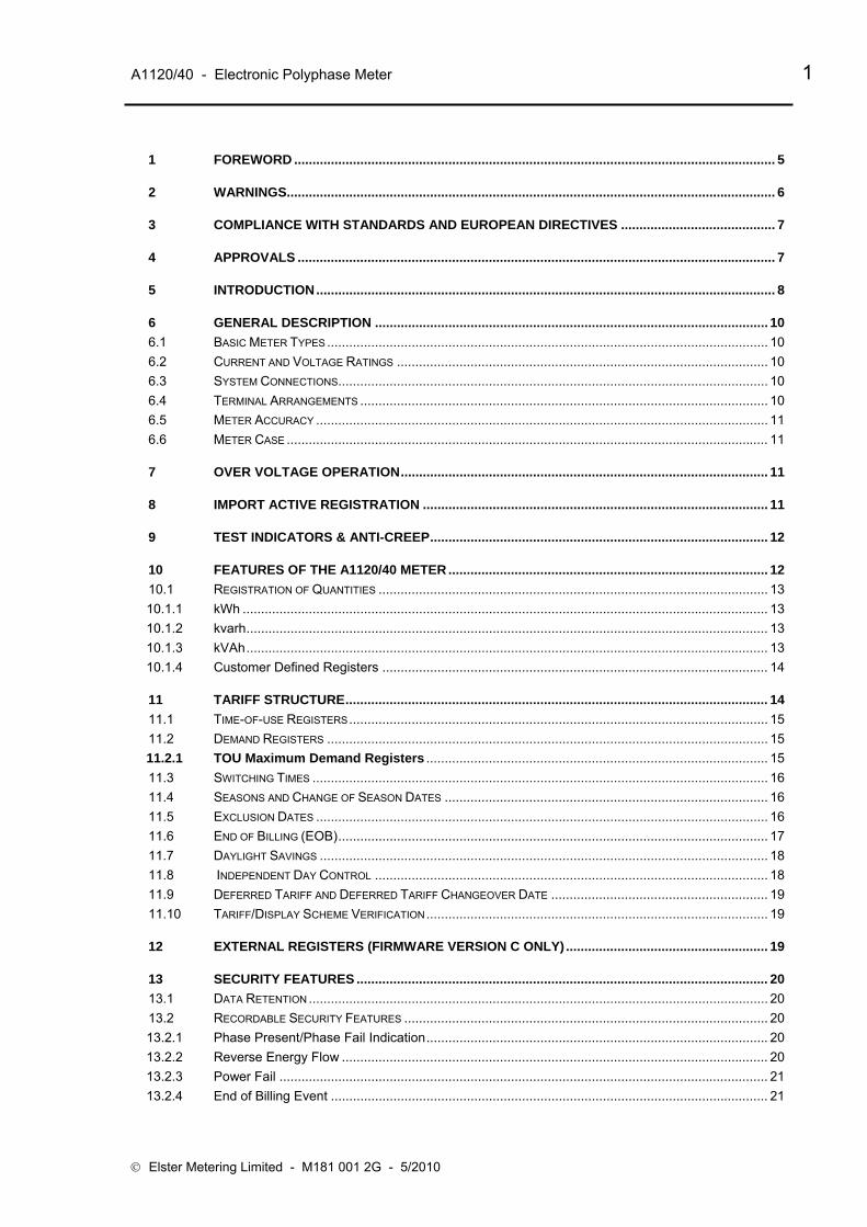
1 FOREWORD ................................................................................................................................... 5
2 WARNINGS..................................................................................................................................... 6
3 COMPLIANCE WITH STANDARDS AND EUROPEAN DIRECTIVES .......................................... 7
4 APPROVALS .................................................................................................................................. 7
5 INTRODUCTION............................................................................................................................. 8
6 GENERAL DESCRIPTION ........................................................................................................... 10 6.1 BASIC METER TYPES ........................................................................................................................ 10 6.2 CURRENT AND VOLTAGE RATINGS ..................................................................................................... 10 6.3 SYSTEM CONNECTIONS..................................................................................................................... 10 6.4 TERMINAL ARRANGEMENTS ............................................................................................................... 10 6.5 METER ACCURACY ........................................................................................................................... 11 6.6 METER CASE ................................................................................................................................... 11
7 OVER VOLTAGE OPERATION.................................................................................................... 11
8 IMPORT ACTIVE REGISTRATION .............................................................................................. 11
9 TEST INDICATORS & ANTI-CREEP............................................................................................ 12
10 FEATURES OF THE A1120/40 METER ....................................................................................... 12 10.1 REGISTRATION OF QUANTITIES .......................................................................................................... 13 10.1.1 kWh ............................................................................................................................................... 13 10.1.2 kvarh.............................................................................................................................................. 13 10.1.3 kVAh.............................................................................................................................................. 13 10.1.4 Customer Defined Registers ......................................................................................................... 14
11 TARIFF STRUCTURE................................................................................................................... 14 11.1 TIME-OF-USE REGISTERS.................................................................................................................. 15 11.2 DEMAND REGISTERS ........................................................................................................................ 15 11.2.1 TOU Maximum Demand Registers ............................................................................................. 15 11.3 SWITCHING TIMES ............................................................................................................................ 16 11.4 SEASONS AND CHANGE OF SEASON DATES ........................................................................................ 16 11.5 EXCLUSION DATES ........................................................................................................................... 16 11.6 END OF BILLING (EOB)..................................................................................................................... 17 11.7 DAYLIGHT SAVINGS .......................................................................................................................... 18 11.8 INDEPENDENT DAY CONTROL ........................................................................................................... 18 11.9 DEFERRED TARIFF AND DEFERRED TARIFF CHANGEOVER DATE ........................................................... 19 11.10 TARIFF/DISPLAY SCHEME VERIFICATION............................................................................................. 19
12 EXTERNAL REGISTERS (FIRMWARE VERSION C ONLY) ....................................................... 19
13 SECURITY FEATURES ................................................................................................................ 20 13.1 DATA RETENTION ............................................................................................................................. 20 13.2 RECORDABLE SECURITY FEATURES ................................................................................................... 20 13.2.1 Phase Present/Phase Fail Indication............................................................................................. 20 13.2.2 Reverse Energy Flow .................................................................................................................... 20 13.2.3 Power Fail ..................................................................................................................................... 21 13.2.4 End of Billing Event ....................................................................................................................... 21

2 A1120/40 - Electronic Polyphase Meter
© Elster Metering Limited - M181 001 2G - 5/2010
13.2.5 Programming Event Log................................................................................................................ 21 13.2.6 CT Ratio Programming.................................................................................................................. 22 13.2.7 Watchdog (Transient Reset).......................................................................................................... 22 13.2.8 In Service Hours ............................................................................................................................ 22 13.2.9 Meter Errors................................................................................................................................... 22 13.2.10 Cover Removal Detection.............................................................................................................. 22 13.2.11 Remaining Internal Battery Life ..................................................................................................... 23 13.3 HISTORICAL DATA ............................................................................................................................ 23
14 METER DISPLAY ......................................................................................................................... 24 14.1 INTRODUCTION................................................................................................................................. 24 14.2 GENERAL ................................................................................................................................... 24 14.3 DISPLAY MODES .............................................................................................................................. 25 14.3.1 Default Mode ................................................................................................................................ 25 14.3.2 Utility Mode .................................................................................................................................. 26 14.3.3 ENGLISH DISPLAY............................................................................................................................. 26 14.3.4 OBIS Display ................................................................................................................................ 26 14.4 Displayable Data.......................................................................................................................... 27 15 USING THE PUSHBUTTONS....................................................................................................... 28
16 COMMUNICATIONS..................................................................................................................... 28 16.1 OPTICAL COMMUNICATIONS PORT...................................................................................................... 28 16.2 OPTIONAL RS232 PORT ................................................................................................................... 29 16.2.1 Modem Power Supply ................................................................................................................... 29 16.2.2 Resetting the Power Supply .......................................................................................................... 29 16.3 DATA STREAM MODE........................................................................................................................ 29
17 PROGRAMMING THE METER..................................................................................................... 30
18 REAL TIME CLOCK AND CALENDAR........................................................................................ 30
19 BATTERY BACK-UP .................................................................................................................... 31 19.1 INTERNAL BATTERY .......................................................................................................................... 31 19.1.1 INTERNAL BATTERY MONITORING....................................................................................................... 31
20 MODULE/BATTERY CARRIER.................................................................................................... 32 20.1 COMMUNICATIONS MODULE............................................................................................................... 32 20.2 EXTERNAL BATTERY MODULE............................................................................................................ 32
21 OUTPUT........................................................................................................................................ 32 21.1 CUSTOMER CONFIGURABLE AUXILIARY OUTPUT (SO AND RELAY)......................................................... 33 21.2 TEST INDICATION (MANUFACTURING OPTION) ...................................................................................... 34
22 ADDITIONAL VOLTAGE TERMINALS ........................................................................................ 34
23 LOAD PROFILE RECORDING (A1140) ....................................................................................... 34
24 INSTRUMENTATION.................................................................................................................... 35
25 TECHNICAL DATA....................................................................................................................... 36

Operating & Maintenance Instructions 3
26 INSTALLATION ............................................................................................................................ 37 26.1 UNPACKING ................................................................................................................................... 37 26.2 HANDLING ................................................................................................................................... 37 26.3 STORAGE ................................................................................................................................... 37 26.4 INSTALLATION SITE........................................................................................................................... 37 26.5 ELECTROMAGNETIC COMPATIBILITY (EMC) ........................................................................................ 37 26.6 FIXING AND CONNECTION.................................................................................................................. 38
27 COMMISSIONING......................................................................................................................... 39
28 MAINTENANCE............................................................................................................................ 40
29 DISPOSAL AND RECYCLING ..................................................................................................... 40 FIGURE 1 - MODEL CODE................................................................................................................................ 41 FIGURE 1 - MODEL CODE (CONTINUED) ........................................................................................................... 42 FIGURE 2 - A1120/40 METER ......................................................................................................................... 43 FIGURE 3 - TYPICAL NAMEPLATE ..................................................................................................................... 44 FIGURE 4 - LOAD CURVES............................................................................................................................... 45 FIGURE 5 - TERMINAL ARRANGEMENTS ............................................................................................................ 46 FIGURE 5A - TERMINAL CONFIGURATIONS........................................................................................................... 47 FIGURE 6 - DIMENSIONS, FIXING CENTRES ....................................................................................................... 48 FIGURE 7 - A1120/40 DISPLAYS ..................................................................................................................... 49 FIGURE 7 - A1120/40 DISPLAYS (CONTINUED).................................................................................................. 50 FIGURE 8 - DISPLAY TABLE ............................................................................................................................. 51 FIGURE 8 - DISPLAY TABLE (CONTINUED).......................................................................................................... 52 FIGURE 8 - DISPLAY TABLE (CONTINUED).......................................................................................................... 53 FIGURE 8 - DISPLAY TABLE (INSTRUMENTATION) ............................................................................................... 54 FIGURE 9 - PASSWORD ACCESS LEVELS .......................................................................................................... 55
APPENDIX A - CHECKING KWH AND KVARH REGISTRATION ACCURACY........................................... 56 A1 INTRODUCTION................................................................................................................................. 56 A2 CHECKING METER ACCURACY USING THE LED TEST INDICATOR .......................................................... 56 A2.1 COMPARING THE NUMBER OF LED PULSES WITH SUBSTANDARD METER REGISTER ADVANCE .................... 56 A2.2 Comparing LED pulses with substandard meter pulses ................................................................ 57 A3 CHECKING METER REGISTRATION ACCURACY FROM REGISTER ADVANCES............................................ 57 A3.1 Using the 'Dial Test' values on the meter display .......................................................................... 57
APPENDIX B - RS232 MULTI-DROP MODE ............................................................................................... 58 B1 RS232 MULTI-DROP INSTALLATION PROCEDURE................................................................................. 58
4 A1120/40 - Electronic Polyphase Meter
© Elster Metering Limited - M181 001 2G - 5/2010
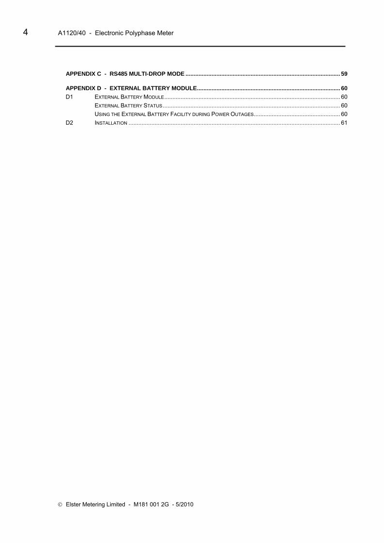
APPENDIX C - RS485 MULTI-DROP MODE ............................................................................................... 59
APPENDIX D - EXTERNAL BATTERY MODULE........................................................................................ 60 D1 EXTERNAL BATTERY MODULE............................................................................................................ 60 EXTERNAL BATTERY STATUS............................................................................................................. 60 USING THE EXTERNAL BATTERY FACILITY DURING POWER OUTAGES..................................................... 60 D2 INSTALLATION .................................................................................................................................. 61

Operating & Maintenance Instructions 5
1 FOREWORD
HEALTH AND SAFETY
Compliance with Instructions in this Manual The instructions and information in this manual are provided in compliance with Section 6 of the UK Health and Safety at Work Act, as amended by Schedule 3 of the Consumer Protection Act 1987.
The purchaser is responsible for making sure that everyone, whether in his employment or not, who will be associated with the products supplied by Elster Metering Systems, and to which these instructions and information apply, are made familiar with the contents of this manual.
This applies to all persons who may be involved in activities such as unpacking, inspecting, testing, setting, cleaning, installing, commissioning, operating, maintaining, decommissioning or disposing of the products.
Safety of Persons using Electrical Products Employers have a duty to ensure, as far as is reasonably practicable, the Health, Safety and Welfare at Work of all their employees. Employers must therefore ensure that employees are informed, trained and supervised and use proper working procedures to ensure the safety of themselves and others.
The information provided in this manual is intended to ensure that products are properly installed and otherwise handled in order to maintain them in a safe condition.
In the UK, employers have duties under the Health and Safety at Work Act 1974 and the various regulations stemming therefrom.
In countries outside the UK, employers should ensure proper compliance with the Health and Safety Legislation that is applicable to them.
Putting into Service Products supplied by Elster Metering Systems have been designed and manufactured, in accordance with appropriate standards, to operate under specified conditions, when properly installed.
The purchaser or delegated contractor is responsible for the "Putting into Service" of any Elster Metering Systems products that have been supplied as "Non-connected". All related activities must therefore be carried out with due regard to any applicable legislation, standards and good practice.

6 A1120/40 - Electronic Polyphase Meter
© Elster Metering Limited - M181 001 2G - 5/2010
2 WARNINGS
WARNINGS
Internal Electronic Circuits Parts of the internal electronic circuits of these meters are, due to technical necessity, connected to PHASE VOLTAGES.
Dangerous voltages are present A Terminal Cover Plate must always be fitted to the A1120/40 meter to protect the main meter terminals. If the Terminal Cover Plate is not fitted to the A1120/40 meter, all supplies to the meter must be isolated before a module, module peripheral equipment or external battery module is installed or removed.
Failure to do so may result in electric shock.
Caution
Installation of a faulty module or module peripheral equipment may affect the main meter functionality.
Removal of the main cover invalidates the certification of certified meters.
Liquid Crystal Display Liquid crystals are toxic. If a display is damaged, avoid contact with the liquid. If the liquid makes contact with the skin it must be washed off immediately with water.
Seek medical advice.
Batteries The meter contains an internal Lithium manganese dioxide primary cell. This battery is completely safe under normal conditions. However, it must never be recharged, disassembled, heated above 100° C, incinerated, or have the contents exposed to water.
Fire, explosion or severe burns may result if these instructions are disregarded.
In the interests of safety, environmental protection and possible legislation, Lithium batteries require careful disposal. Before arranging for the disposal of these cells, users should satisfy themselves that the proposed means of disposal is both safe and compliant with local legislation requirements.
Elster Metering Systems would like to draw the user's attention to the International Standard for Lithium Batteries - IEC 60084-4 - which gives further information about the handling, storage, transport and disposal of lithium cells.
Elster Metering Systems should be contacted by the user should difficulties arise in arranging proper disposal. They will if practical help the user identify safe disposal means.
An optional External Battery Module supports the display and optical communications during power outages. A non-rechargeable “alkaline” (alkaline zinc manganese dioxide) PP3 (IEC 6LR61) battery is used.
This battery is completely safe under normal conditions. It must not be recharged, disassembled, short-circuited, overheated or incinerated. It contains corrosive materials.
Used batteries should be disposed of in compliance with local legislation requirements.

Operating & Maintenance Instructions 7
3 COMPLIANCE WITH STANDARDS AND EUROPEAN DIRECTIVES Meters are marked with the European CE mark, in accordance with the Marking Directive 93/68/EEC, to indicate compliance with the requirements of the EMC Directive 89/336/EEC.
Safety requirements for meters are addressed in specific metering standards outlined below.
The CE Mark does not denote compliance with the European Low Voltage Directive 73/23/EEC, which specifically excludes electricity meters.
The A1120/40 meter measures active energy, according to the requirements of - EN 62053-21/22:2003 for indoor kWh meters of Protective Class II and Accuracy Class 0.5s, 1 or 2 (MID) - Annex MI-003, kWh Class A, B or C.
The meter measures reactive energy in accordance with EN 62053-23:2003, Class 2 or Class 3.
Meters displaying OBIS Identification Codes meet the requirements of IEC 62056-61.
The degree of ingress protection is to IP53, IEC 60529:1989.
The meter complies with DIN 43857 Part 2 and Part 4 - dimensional requirements (except for the top fixing centres).
The meter complies with the essential requirements of the EC Directive 2004/22/EC on Measuring Instruments (MID).
The meter complies with the general requirements and particular requirements of EN 50470 Parts 1 & 3, and complies with Class M2 Mechanical environment and Class E2 Electromagnetic Environment.
Devices for metering and billing electrical energy described in this manual are supplied for use in a ‘Fixed Installation’ only. Devices described are a ‘component of a system only’ and therefore outside the scope of European Directives 2002/95/EC RoHS (Restriction of the Use of Certain Hazardous Substances in Electrical Equipment) and 2002/96/EC WEEE (Waste Electrical and Electronic Equipment).
4 APPROVALS kWh/kvarh energy meters are approved by the Office of Gas and Electricity Markets (OFGEM) in compliance with European and British metering legislation.

8 A1120/40 - Electronic Polyphase Meter
© Elster Metering Limited - M181 001 2G - 5/2010
5 INTRODUCTION
The A1120/40 has been designed to meet the changing needs of the Electricity Supply Industry.
The meter offers a ‘modular’ solution for remote communications, allowing the meter to be integrated into an AMR system at any time. Flexibility in communications provides the Utility with the means to employ the most cost effective communications method. The RJ11 connector provides power for a modem removing any requirement for external connections. The modem fits neatly under the terminal cover providing a high degree of protection against fraud or tampering.
Communications are provided via the optical (IEC 62056-21) port and are supported by data stream mode, allowing fast reading of meter data. The A1140 permits up to 90 days of load profile data to be collected in less than 30 seconds. The RJ11 socket provides optional RS232 communications allowing remote access to the same data as the optical port. This port can be multi-dropped, allowing access to up to 10 meters in a single installation. A further option allows a pulsed output to be transmitted via the meter’s auxiliary terminals.
The meter is available in a number of variants that measure combinations of active energy, four quadrant reactive energy and kVAh. Two customer defined registers can be used to summate energy from any like unit registers. Instrumentation quantities to aid installation can be included in the display sequence.
Firmware Version C allows 12 External Registers to display data from an external source such as a gas or water meter. The registers are written to by an intelligent source via the RS232 port.
The meter offers extensive security data which includes a programming log with user ID. Further security can be provided as an option with terminal cover and main cover removal detection. As an alternative option, the latter detection switch can instead be used to allow the CT ratio to be changed.
The Liquid Crystal Display (9.8mm) has large characters that can be viewed from a wide angle. The display sequence is programmable and can be auto-cycle, step or utility. Displayed information can have English language identifiers or OBIS (Object Identification System) codes. The OBIS codes can be changed via the Power Master Unit.
Power Master Unit software provides a user-friendly WindowsTM graphical interface for programming the meter and reading meter data.
The meters are approved to:
EN 62053-21/22 for kWh accuracy - Class 0.5s, 1 or 2 EC Directive 2004/22/EC (MID) - Class A, B or C EN 62053-23 for kvarh accuracy - Class 2 or Class 3
The meter has an ingress protection rating of IP53 to IEC 60529:1989.
The following main variants of the meter (configured at manufacture) are available:
Import kWh
Import kWh, Q1 and Q4 kvarh
Import kWh, Q1, Q2, Q3, Q4 kvarh, kVAh 1
Import/Export kWh
Import/Export kWh, Q1, Q2, Q3, Q4 kvarh
Import/Export kWh, kVAh 1-2
Import/Export kWh, Q1, Q2, Q3, Q4 kvarh, kVAh 1-2
Operating & Maintenance Instructions 9
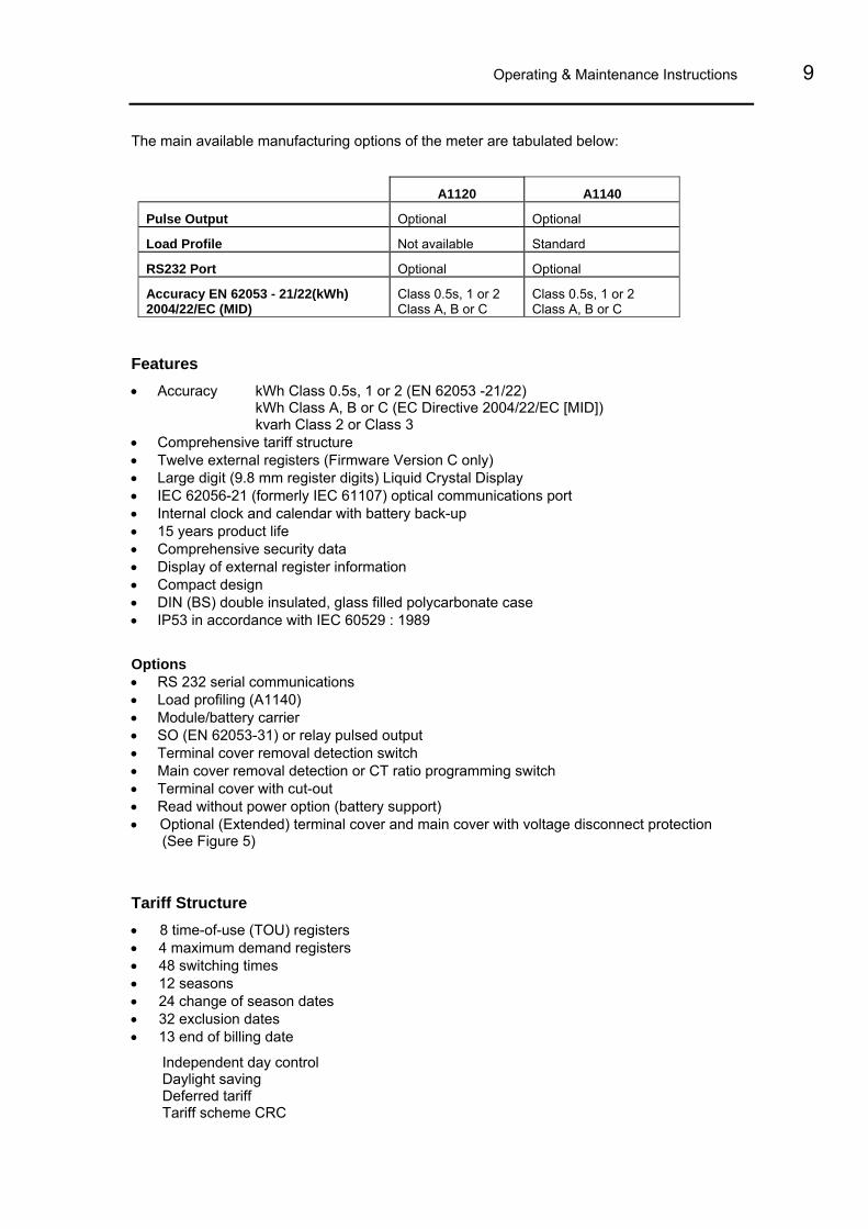
The main available manufacturing options of the meter are tabulated below:
A1120 A1140
Pulse Output Optional Optional
Load Profile Not available Standard
RS232 Port Optional Optional
Accuracy EN 62053 - 21/22(kWh) 2004/22/EC (MID)
Class 0.5s, 1 or 2 Class A, B or C
Class 0.5s, 1 or 2 Class A, B or C
Features • Accuracy kWh Class 0.5s, 1 or 2 (EN 62053 -21/22) kWh Class A, B or C (EC Directive 2004/22/EC [MID])
kvarh Class 2 or Class 3 • Comprehensive tariff structure • Twelve external registers (Firmware Version C only) • Large digit (9.8 mm register digits) Liquid Crystal Display • IEC 62056-21 (formerly IEC 61107) optical communications port • Internal clock and calendar with battery back-up • 15 years product life • Comprehensive security data • Display of external register information • Compact design • DIN (BS) double insulated, glass filled polycarbonate case • IP53 in accordance with IEC 60529 : 1989 Options • RS 232 serial communications • Load profiling (A1140) • Module/battery carrier • SO (EN 62053-31) or relay pulsed output • Terminal cover removal detection switch • Main cover removal detection or CT ratio programming switch • Terminal cover with cut-out • Read without power option (battery support) • Optional (Extended) terminal cover and main cover with voltage disconnect protection
(See Figure 5) Tariff Structure • 8 time-of-use (TOU) registers • 4 maximum demand registers • 48 switching times • 12 seasons • 24 change of season dates • 32 exclusion dates • 13 end of billing date
Independent day control Daylight saving Deferred tariff Tariff scheme CRC

10 A1120/40 - Electronic Polyphase Meter
© Elster Metering Limited - M181 001 2G - 5/2010
6 GENERAL DESCRIPTION
6.1 Basic Meter Types LM… DIN/BS Termination
6.2 Current and Voltage Ratings Unless otherwise indicated on the nameplate, the following meter ratings are available:
Voltage Current Frequency 3 Element Meters *220 - 240V L-N 105 - 127V L-N
2 Element Meters 220 - 240V L-L 105 - 127V L-L
20 - 100A (Direct connected) 10 - 100A (Direct connected) 5 - 100A (Direct connected) 1 - 2A (CT operated) *5 - 10A (CT operated) 1 - 10A (CT operated)
50 or 60Hz
* Ratings available for Class 0.5s, CT operated variant
Note - 105 - 127V meters and 60Hz meters are not OFGEM or MID approved.
6.3 System Connections Meters can be supplied for direct connected or CT, 3 element (3 phase, 4 wire) or 2 element (3 phase 3 wire) applications and have the following connection capability:
Number of Elements Connection capability
3 * 3 phase, 4 wire
2 phases of 3 phase, 4 wire
2 phase, 3 wire
1 phase, 3 wire
1 phase, 2 wire
2 * 3 phase, 3 wire * Connections available for Class 0.5s, CT operated variant
6.4 Terminal Arrangements
Current Terminals
8.2mm diameter bore, 2 x M6 Combi pinch screws
9.0mm diameter bore, 2 x M6 Combi pinch screws
9.5mm diameter bore, 2 x M6 Combi pinch screws
Auxiliary Terminals 3.2mm diameter bore, M3 Combi pinch screws Meter nameplates (see Figure 3 for example) are marked with the rated current, reference voltage, frequency and the relevant meter constant (pulses/kWh, pulses/kvarh).
Connection diagrams (See Figure 5A for examples) are shown underneath the terminal cover.
A Terminal Cover Plate must be fitted to protect the meter Main Terminals.
Operating & Maintenance Instructions 11
6.5 Meter Accuracy
The A1120/40 meter measures active energy, in accordance with the requirements of - EN 62053-21/22 for indoor kWh meters of protective Class II and accuracy Class 0.5s, 1 or 2, EC Directive 2004/22/EC (MID) - Class A, B or C
The design of the meter ensures life long stability. There are no on-site adjustments.
The meter measures reactive energy in accordance of the requirements of EN 62053-23 for kvarh meters for reactive energy Class 2 or Class 3.
Typical accuracy curves are shown in Figure 4.
6.6 Meter Case The case is double insulated to protective Class II.
The case provides an ingress protection rating of IP53 in accordance with IEC 60529:1989.
The base is light beige coloured polycarbonate.
A separate phenolic terminal block conforms to DIN 43857 Part 2 and 4.
The extended terminal cover is moulded in light beige coloured polycarbonate. An option with a cut-out is available.
The main cover is moulded in tinted, clear polycarbonate.
Figure 6 illustrates the outline and fixing dimensions.
The main cover is secured by two sealable screws. Two separate sealable screws secure the terminal cover.
The terminal cover plate protects the meter main terminals.
An optional main cover prevents access to the voltage disconnect links (See Figure 5)
A holder for a module/battery that attaches to the base under the terminal cover is available as an option.
7 OVER VOLTAGE OPERATION
The meter has been designed to withstand a phase - neutral voltage of √3 x 1.1 Uref (i.e. 440V for 230V meters) for an indefinite period. When tested over a 12 hour duration the change in meter error was less than 0.4%.
8 IMPORT ACTIVE REGISTRATION Import Active registration can be configured at manufacture to one of the following:
Import Active Units Only – Import Active Units measures the sum of all phases, when the total system flow is positive.
Positive (kWh [L1] + kWh [L2] + kWh [L3])
Power Flow Insensitive Mode - Power Flow Insensitive Mode allows the meter to increment its main kWh register regardless of whether the system energy flow is import or export.
│(kWh [L1] + kWh [L2] + kWh [L3])│

12 A1120/40 - Electronic Polyphase Meter
© Elster Metering Limited - M181 001 2G - 5/2010
The Reverse Energy Event Alarm, Reverse Energy Count and Reverse kWh Register respond only to reverse power flow and continue to function as in normal operation.
Theft Resistant Measurement - Theft Resistant Measurement mode measures the sum of the modulus of each phase (│kWh [L1]│ + │kWh [L2]│ + │kWh [L3]│)
The Reverse Energy Event Alarm, Reverse Energy Count and Reverse kWh Register respond only to reverse power flow and continue to function as in normal operation.
Note 1: Power Flow Insensitive Mode and Theft Resistant Measurement may not be allowed in certain countries due to local regulations.
Note 2: Theft resistant measurement is not appropriate for meters connected to 3 phase 3 wire systems.
9 TEST INDICATORS & ANTI-CREEP
Test Indicators
Two red test output LEDs (for kWh and kvarh) are provided which pulse in accordance to the following configurations:
Import only meter - The LED pulses for forward system energy only
Import meter with Power Flow Insensitive enabled - The LED pulses for forward and reverse system energy
Import meter with Theft Resistant measurement enabled – The pulsing LED reflects theft resistant measurement.
Import/export meter - The LED pulses for import and export energy
See Section 25 (Technical Data) for LED specification.
Anti-creep
The Wh and varh anti-creep threshold is set at manufacture to a value appropriate to the meter rating and accuracy class. For a 4 wire meter connected with less than 3 elements energised, the value adjusts to maintain an appropriate current threshold level. Each Test Indicator LED is continuously illuminated when the meter's anti-creep lock is operating for kWh and kvarh respectively.
10 FEATURES OF THE A1120/40 METER The meter contains numerous features, combinations of which can be selected to provide the required metering function. Main variants are selected at manufacture (See Section 5). Programmable features are selected using Power Master Unit Software that runs on an IBM or compatible PC.
This software is available from Elster Metering Systems and is described in M181 001 3.
Note: The features available will depend on the meter variant (See Section 5).

Operating & Maintenance Instructions 13
10.1 Registration of Quantities 10.1.1 kWh
kWh total import (active energy)
kWh total export (active energy)
Total import and total export quantities are registered separately. The measurement discrimination is such that, as the power factor of any load from 0.05Ib to Imax is varied over 360°, the import and export registers will never advance together. The resolution of registration is 1mWh.
10.1.2 kvarh Q1 kvarh Inductive Import
Q2 kvarh Capacitive Import
Q3 kvarh Inductive Export
Q4 kvarh Capacitive Export
All four quadrants are registered separately. The resolution of registration is 1mvarh.
kvarh is derived using the phase shift method.
Note: The diagram shows a representation of the quadrants. The active quadrant can be shown on the display.
10.1.3 kVAh kVAh is derived from the measured kWh and kvarh values
The calculation uses the formula: kVAh = √ ([kWh]2 + [kvarh]2 )
There are two kVAh registers. These can each be configured to accept pulses from any combination of quadrants e.g.
Q1 Q2 Q3 Q4
kWh * * kVAh - to match 2 electromechanical meters
kvarh * *
Note: Real and reactive energy for each phase is respectively summated prior to kVAh calculation.
E
XPO
RT A
CTIV
E PO
WER
I
MPORT REACTIVE POWER
EXPORT REACTIVE POWER
Q1Q2
Q3 Q4
+Q
-Q
+P-P
Lagging/Indu
ctive
Lea
ding
/Cap
acitiv
e
Lagging/Inductive Leading/Capacitive

14 A1120/40 - Electronic Polyphase Meter
© Elster Metering Limited - M181 001 2G - 5/2010
10.1.4 Customer Defined Registers Two Customer Defined (CD) Registers are provided. These are cumulative registers which can be used throughout the tariff scheme and load profile data and are programmable to accept consumption from any two of the following like-unit registers:
kWh import
kWh export
Q1 kvarh
Q2 kvarh
Q3 kvarh
Q4 kvarh
kVAh 1
kVAh 2
Examples of their use are:
CD Register 1 Total kWh kWh import + kWh export = Total kWh
CD Register 2 Total Import kvarh Q1 + Q2 = Total Import kvarh
The contents of the Customer Defined Registers can be viewed on the display.
11 TARIFF STRUCTURE The tariff structure repeats year on year and comprises the following features: 8 Time-of-use (TOU) registers 4 Maximum demand registers 48 Switching times 12 Seasons 24 Change of season dates 32 Exclusion dates 13 End of billing dates Daylight savings Independent day control Deferred tariff Tariff scheme CRC
At least one Season must be programmed into the meter for TOU registers to be available.

Operating & Maintenance Instructions 15
11.1 Time-of-use Registers A total of 8 Time-of-use (TOU) registers are provided. Each TOU register has a single source that can be selected from one of the following: Import kWh Export kWh Q1 kvarh Q2 kvarh Q3 kvarh Q4 kvarh kVAh 1 kVAh 2 Customer Defined Register 1 Customer Defined Register 2
Each TOU Register is independently time controlled so that registration can take place over a restricted time period.
The contents of each TOU Register can be viewed on the display along with the active rate(s).
11.2 Demand Registers The A1120/40 provides the rising demand value associated with each of the 10 registered quantities specified in Section 11.1. The demand integration period can be 1, 2, 3, 4, 5, 6, 10, 15, 20, 30 or 60 minutes.
In A1140 meters the integration period used for the demand registers is the same as the load profile integration period.
During any period, the rising demand value is calculated by measuring the energy consumed to a point in a period, then scaling the measured value by a factor equal to the ratio of the demand period to a total hour interval.
Rising Demand = Energy recorded in current period x 60 p minutes in demand period
The contents of each Rising Demand Register can be viewed on the display.
11.2.1 TOU Maximum Demand Registers The meter has 4 maximum demand registers, each with an independent source selectable from one of the 10 rising demands.
The meter records the three highest maximum demand values (along with time and date stamp) that can be sampled on a continuous basis (24-hour period) or over a restricted time period. At the end of each billing period, the greatest of the three demands is added to a corresponding cumulative maximum demand register. The maximum demand registers are then set to zero.

16 A1120/40 - Electronic Polyphase Meter
© Elster Metering Limited - M181 001 2G - 5/2010
11.3 Switching Times
Up to 48 switching times can be set, each allocated to a specified season. Each switching event can be enabled for any combination of days of the week. These are the transition times when one or more TOU registers become active or inactive.
Each switching time is defined in hours and minutes. A 24-hour clock is used.
The above diagram shows the tariff for TOU1 and TOU2. TOU1 is active from 06:00 to 18:00. TOU2 is active from 18:00 to 06:00. It is possible for none or multiple TOU registers to be programmed to be active at any particular time period.
11.4 Seasons and Change of Season Dates Up to 12 Seasons may be specified and at least one Season must be programmed for the TOU registers to be available. Each Season is activated by one or more Change of Season Dates.
Up to 24 Change of Season Dates are available, each date specifying the start of a new Season. These may refer to a different Season, or the same Season may be used more than once in a year.
The old Season ends at the instant the new Season starts. A new Season starts at 00.00 of the specified day. Start dates are specified as absolute (dd.mm) dates.
The diagram shows three Seasons. Season 1 is in operation from October to February, Season 2 from March to May and Season 3 from June to September.
11.5 Exclusion Dates There may be special days in the year when the tariff does not follow the normal pattern, e.g. public holidays. These can be taken care of by invoking Exclusion Dates.
Up to 32 Exclusion Dates can be programmed.
06:00 18:00
24 hours
Switching times
Operating & Maintenance Instructions 17
These dates will fall into one of three categories:
1 Dates which are fixed for every year e.g. December 25th - programmed by absolute dd.mm
2 Dates which fall on the same day of the month every year e.g. the first Monday in May
3 Dates which vary from year to year e.g. Easter Monday - defined using dd.mm.yy
For each Exclusion Date the meter may be programmed to:
- Use the switching times for a different weekday of the current season
- Use the switching times for the same weekday but a different season
- Use the switching times for a different weekday of a different season
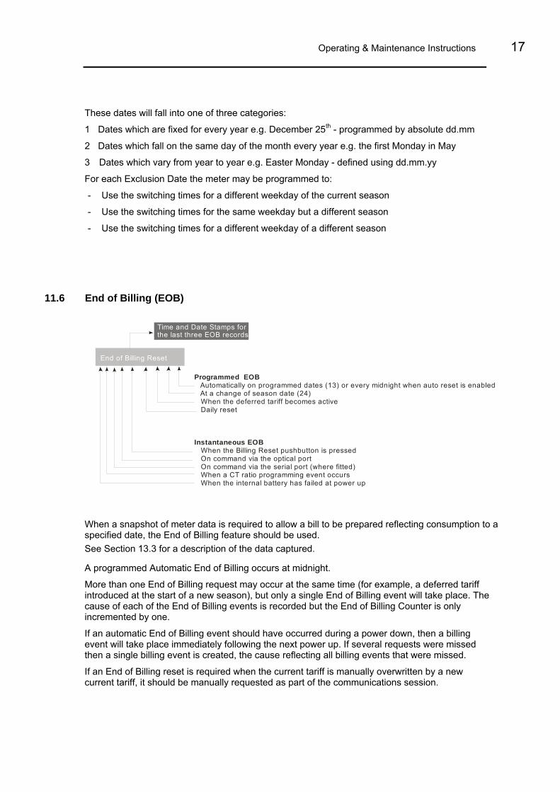
11.6 End of Billing (EOB)
End of Billing Reset
Time and Date Stamps forthe last three EOB records
Programmed EOB
Instantaneous EOB
Automatically on programmed dates (13) or every midnight when auto reset is enabled At a change of season date (24) When the deferred tariff becomes active Daily reset
When the Billing Reset pushbutton is pressed On command via the optical port On command via the serial port (where fitted) When a CT ratio programming event occurs When the internal battery has failed at power up
When a snapshot of meter data is required to allow a bill to be prepared reflecting consumption to a specified date, the End of Billing feature should be used. See Section 13.3 for a description of the data captured.
A programmed Automatic End of Billing occurs at midnight.
More than one End of Billing request may occur at the same time (for example, a deferred tariff introduced at the start of a new season), but only a single End of Billing event will take place. The cause of each of the End of Billing events is recorded but the End of Billing Counter is only incremented by one.
If an automatic End of Billing event should have occurred during a power down, then a billing event will take place immediately following the next power up. If several requests were missed then a single billing event is created, the cause reflecting all billing events that were missed.
If an End of Billing reset is required when the current tariff is manually overwritten by a new current tariff, it should be manually requested as part of the communications session.

18 A1120/40 - Electronic Polyphase Meter
© Elster Metering Limited - M181 001 2G - 5/2010
Mon Tue Wed Thu Fri Sat Sun1 2 3 Switching programs
Auto Reset initiates a Billing Reset every midnight. When Auto Reset is enabled there is an option to inhibit the reset of the Maximum Demand Registers.
A message that a Billing Reset has been initiated is displayed with a code showing the cause of the reset (See Figure 8, Display Table).
At each Billing Reset the oldest of the fifteen historical data records is overwritten. Time and date stamps, together with causes are stored for the last three End of Billing events.
End of Billing Lock-out
A further End of Billing can be inhibited via the Power Master Unit for either:
- Up to 255 minutes
- Until the next midnight boundary
Note: This only inhibits instantaneous end of billing requests, either via the pushbutton or communications setting, not programmed End of billing events.
11.7 Daylight Savings The meter provides 2 Daylight Savings dates whereby the clock can be advanced by one or two hours at the start of the summer and can be retarded by one or two hours at the end of the summer.
The day on which a Daylight Saving occurs is programmable, with the choice of the first, second, third, fourth or last specified weekday in a specified month.
The algorithm used will identify the correct calendar dates for the next 50 years.
All of the following will reflect Daylight Savings:
Automatic End of Billing
Switching times within the tariff definition
Time and date stamps (For firmware Version C meters, daylight savings time and date stamps can be referenced to base time or daylight savings time)7.
Optionally load profile (A1140 only)
11.8 Independent Day Control The meter has the facility to have a different switching program consisting of several switching times running on different days of the week. An example of a switching program is below.

Operating & Maintenance Instructions 19
11.9 Deferred Tariff and Deferred Tariff Changeover Date A second tariff can be programmed in the meter that will take effect from a programmed date.
An option to perform an End of Billing on the Deferred Tariff Changeover Date is available as part of the deferred tariff structure.
11.10 Tariff/Display Scheme Verification The meter generates a checksum (CRC-16) of the tariff/display scheme currently residing in the meter. The checksum can be included as part of the display sequence, and also compared with a tariff checksum generated by the Power Master Unit. This allows quick verification, either locally or remotely, that the correct tariff/display scheme resides within the meter.
12 EXTERNAL REGISTERS (FIRMWARE VERSION C ONLY)
Firmware Version C of the A1120/40 has 12 External Registers that can be used to display data from an external source such as a gas or water meter. The registers are accessed via an intelligent source (such as a modem) and can be viewed on the A1120/40 meter display.
The registers are configured as three sets, External set 1, External set 2 and External set 3.
Each register set has four associated registers and has its own formatting options that can be configured using the Power Master Unit (Number of digits, Number of decimal places and display scale).
The Display shows Register 2 of External Set 1
Each register has 16 digits. The user is able to select English text or create an OBIS code for each of the twelve external registers.

20 A1120/40 - Electronic Polyphase Meter
© Elster Metering Limited - M181 001 2G - 5/2010
13 SECURITY FEATURES
Password Protection
The A1120/40 meter uses a Password as part of the security algorithm. The passwords must be entered in upper case. Password protection can be disabled at manufacture if required. Four levels of access are available. Entering the correct password for levels 0, 1, 2 and 3 allows the functions in Figure 9 to be performed, higher levels giving access to the lower levels. Passwords may also be set to defaults using the Power Master Unit. It is important to note that the integrity of the A1120/40 meter passwords should always be protected. This can be achieved by ensuring the ability to change passwords is controlled and only made available to Administrative Personnel. The level 3 password should be changed at regular intervals. It may be appropriate for no more than 100 meters to be protected by the same level 3 password. Calibration values, zeroing of registers etc. are protected by a security link that is removed at the factory before the meter is sealed.
13.1 Data Retention All cumulative register and time of use data is saved to non-volatile memory every time the power to the meter fails and also every 2 hours. The data is recovered when power is restored to the meter.
All data is retained for the nominal life of the meter.
13.2 Recordable Security Features The following security features are available and can be included in the display sequence:
13.2.1 Phase Present/Phase Fail Indication The meter detects and stores the number of phase fail events to a maximum of 65535. The register will then roll over to 0. A time and date stamp of the three most recent events is recorded. The phase fail threshold can be set between 0 and 250 V. Phase indication on the display (L1, L2, L3) has the following options:
Indicator ‘on’ when phase present
Indicator ‘on’ when phase failed
Where a meter is to be used on a supply with less than 4 wires, it is possible to disable the monitoring and display of phases L2 and L3.
13.2.2 Reverse Energy Flow Reverse run event count
The meter detects and stores the number of reverse running events to a maximum of 65535. The register will then roll over to 0.
A time and date stamp of the three most recent events is recorded.

Operating & Maintenance Instructions 21
The count and time and date stamps can be included in the display sequence. An event is detected if the meter runs in reverse for a period greater than 5 seconds.
Reverse energy reading
Irrespective of whether the meter is set to import only power flow insensitive mode, reverse kWh power flow will be independently recorded.
Theft Resistant Measurement
Theft Resistant Measurement mode measures the sum of the modulus of each phase (│kWh [L1]│ + │kWh [L2]│ + │kWh [L3]│)
The Reverse Energy Event Alarm, Reverse Energy Count and Reverse kWh Register respond only to reverse power flow and continue to function as in normal operation.
Reverse energy Alarm (Import only meter)
The reverse run indication, which responds to the total system power flow, can be inhibited if required.
Per Phase Reverse Run Indication
Any phase in reverse run can be indicated on the Liquid Crystal Display by flashing the L1, L2 or L3 phase indicators.
13.2.3 Power Fail A count of the cumulative number of power downs to a maximum of 65,535 is recorded. The register will then roll over to 0.
A time and date stamp of the three most recent events is recorded. The count and time and date stamps can be included in the display sequence.
13.2.4 End of Billing Event A count of the number of end of billing events to a maximum of 65,535 is recorded. The register will then roll over to 0. Time and date stamps together with the source of the billing reset for the three most recent events is recorded. The count and time and date stamps can be included in the display sequence. The message ‘Reset’ is displayed each time an End of Billing event takes place.
13.2.5 Programming Event Log A count of the number of programming events to a maximum of 65,535 is recorded. A time and date stamp of the three most recent events together with the source (optical or RS232 data port) is recorded. The identity of the programming user is also stored. The count and time and date stamps can be included in the display sequence.
Note: Programming events are communications sessions where the meter configuration or data has been changed. Reading data only does not count as a programming event.

22 A1120/40 - Electronic Polyphase Meter
© Elster Metering Limited - M181 001 2G - 5/2010
13.2.6 CT Ratio Programming The CT ratio can be displayed as a ratio or as a scalar quantity. A count of the number of CT Ratio reprogramming events to a maximum of 65,535 is recorded together with source (Optical or RS232 port) and time and date stamps for the three most recent events. The identity of the programming user is also stored. The count and time and date stamp can be included in the display sequence.
Note: CT Ratio Reprogramming Events are communications sessions where the primary or secondary value of the CT has been changed.
An End of Billing Reset can be requested with a CT ratio change.
A CT Programming switch can be fitted as a manufacturing option. The switch must be activated in order to change the CT ratio. The switch is under the terminal cover and may be protected by a paper seal.
13.2.7 Watchdog (Transient Reset) A count of the number of watchdog resets to a maximum of 65,535 is recorded together with time and date stamps for the three most recent events. The count and time and date stamps can be included in the display sequence.
13.2.8 In Service Hours The elapsed time counter records the cumulative time (to a resolution of 1 hour) the meter has been powered up. The count can be included in the display sequence.
The amount of storage is in excess of 25 years.
13.2.9 Meter Errors
An alarm can be displayed if an error occurs. The alarm and error message (See Figure 8, Display table) can be disabled via the Power Master Unit.
Access to the data is via the optical port, the RS232 data port or on the LCD. A time and date stamp of the three most recent non-fatal error events is recorded where possible.
In the unlikely event that any of the above meter errors occur, a catastrophic failure has been detected and the meter should be returned to Elster Metering for failure investigation.
13.2.10 Cover Removal Detection Main Cover As a manufacturing option the main cover can be fitted with a tamper switch to detect removal. The number of times the cover has been removed to a maximum of 65,535 is recorded together with the time and date stamps of the last three occurrences. The count and time and date stamps can be included in the display sequence.
Note: The main cover removal option is not available when the meter is configured for CT Ratio Programming Switch.

Operating & Maintenance Instructions 23
Terminal Cover As a manufacturing option the meter can be fitted with a tamper switch to detect removal of the terminal cover. The number of times the cover has been removed to a maximum of 65,535 is recorded together with the time and date stamps of the last 3 occurrences.
The count and time and date stamps can be included in the display sequence.
13.2.11 Remaining Internal Battery Life The A1120/40 provides a count of the number of hours of life left in the internal battery. The count can be included in the display sequence.
The count is calculated by subtracting the amount of time the meter has been supported during power outages from the initial battery life estimate.
13.3 Historical Data At each End of Billing the following data is stored to historical registers: Meter Data
• Cumulative Registers • TOU Registers • TOU MD Registers
There are 15 sets of historical registers
Event Data
• Reverse running count, last 3 time and date stamps • Billing events count, last 3 time and date stamps • Power failures count, last 3 time and date stamps • Meter errors, last 3 time and date stamps of non fatal errors • Watchdog resets count, last 3 time and date stamps • Programming events count, last 3 time and date stamps • Phase failures (L1, L2 or L3) count, last 3 time and date stamps • CT ratio programming events count, last 3 time and date stamps • External battery failures count, last 3 time and date stamps • Number of times the terminal cover has been removed, last 3 time and date stamps • Number of times the main cover has been removed, last 3 time and date stamps • In-service hours • Internal battery life Note that for Version C meters the Time and Date Stamps can be in Base Time or daylight Savings Time.

24 A1120/40 - Electronic Polyphase Meter
© Elster Metering Limited - M181 001 2G - 5/2010
14 METER DISPLAY
14.1 Introduction
The A1120/40 meter is fitted with a high contrast liquid crystal display that can be viewed from a wide angle. The main display characters are 9.8mm high.
The display can be configured using the Power Master Unit to display data with English descriptors or OBIS (Object Identification System) format.
The Test Display with a description of the displayed legend (English or OBIS) is shown below.
English IdentifierOBIS Code
EnglishDescrip tion
Reverse Run
Phase Indicators
Chevrons Energy FlowDirection
Alarm
MultiplierX10, X100
Units of QuantityM, k, W, V, A, r, h
MeasurementRegister, Time,Date, Security Data
14.2 General
Display Resolution The resolution of the display can be set at manufacture to 7, 6 or 5 digits. The decimal point indicator can be configured to be a point or a comma and set to 0, 1 or 2 places. kWh Wh mWh
Internal storage is :- 1 2 3 4 5 6 7 8 9 0 1 2 3. 4 5 6 The display is a window of this. e.g. 1 2 3 4 5 6 7 8 9 0 1 2 3. 4 5 6
Seven Digits Six Digits Five Digits 4 5 6 7 8 9 0 5 6 7 8 9 0. 1 6 7 8 9 0. 1 2
5 6 7 8 9 0 6 7 9 9 0. 1 7 8 9 0. 1 2
6 7 8 9 0 7 8 9 0. 1 8 9 0. 1 2
Units of Quantity and Multiplier
The Units of Quantity (Wh, kWh, MWh) and multiplier (x10, x100) displayed are selectable by the Power Master Unit and displayed in the top right corner of the display.
The display opposite shows kWh, x10.

Operating & Maintenance Instructions 25
14.3 Display Modes The display has two modes of operation, Default Mode and Utility Mode. Up to 40 displays can be made available for each mode of operation.
14.3.1 Default Mode The Default Mode can operate in two ways, Auto-cycle or single step.
Auto-cycle
At power up the segment test pattern is shown. This will remain displayed for a period of 3 seconds.
The display will then sequence through the programmed displays, remaining on each display item for one step duration time, called the Auto-cycle step duration (2-30 seconds).
3 seconds Next display 2-30 seconds Step
Step mode is entered by a single press of the Display Pushbutton. The first display in the autocycle sequence is displayed. Further presses of the pushbutton allow the consumer to step through the autocycle display items, and then through the single step display items.
The display will default to autocycle mode at a programmed time after the last press of the display pushbutton.
Display pushbutton press Next display

26 A1120/40 - Electronic Polyphase Meter
© Elster Metering Limited - M181 001 2G - 5/2010
14.3.2 Utility Mode It is necessary to break the seal on the Reset Pushbutton to enter ‘Utility’ mode. The mode is entered by pressing the Reset Pushbutton. ‘Utility’ appears on the display. Single presses of the Display pushbutton will then step through the utility displays. The display will default to autocycle mode at a programmed time after the last press of the Display Pushbutton, or if the Reset Pushbutton is again pressed. Short press Reset Pushbutton
Press Display Pushbutton Next display
14.3.3 English Display
Chevrons & Identifiers
The chevrons on the display have the following meaning: Identifiers
Description
1 2 3 4 5 6 7
Import Security Export
The display identifiers give a description of the main register displayed.
Examples of the display are shown in Figures 7.
A full list of displays is given in Figure 8.
14.3.4 OBIS Display
The OBIS code gives a description of the main register displayed. OBIS Code
Chevron 7 indicates the register is active.
Examples of displays and a full list of displays are given in Figures 7 and 8 respectively. Active
Chevron/Description 1 Import 2 Export 3 - 4 Security 5 - 6 - 7 -

Operating & Maintenance Instructions 27
14.4 Displayable Data A full list of displayable data items is given in Figure 8. Items available will depend on the meter variant. Segment Test Pattern Cumulative Registers
Customer Defined Registers Rising Demand Registers TOU Maximum Demand TOU Registers Historical Registers Security Instrumentation Phase Failure CT Ratio Tariff CRC Meter Errors
Dial Test
For dial testing, the cumulative kWh and kvarh displays can be set to a higher resolution by using the Power Master Unit.
The resolution of the display can be configured to 0, 1, 2, 3 or 4 decimal places
Note: If the display is configured for Wh with no multiplier set, the maximum resolution of the display is 3 decimal places.
The meter will cease using dial test resolution when instructed by the Power Master Unit, or after a programmable number of power cycles.
Display Indicators System Reverse Run Indicator
Phase Failure Indication Per Phase Reverse Run Indication Error/Alarm
Energy Direction Indicators
Communications Indication When communications are taking place the following indicators are displayed in the top left corner of the display.
o Optical communication r RS232 Communication Figure 7 shows examples of the display. The indicators can be disabled via the Power Master Unit.

28 A1120/40 - Electronic Polyphase Meter
© Elster Metering Limited - M181 001 2G - 5/2010
15 USING THE PUSHBUTTONS Two pushbuttons can be provided as an option. Their use is as follows:
Default Display Mode A short press of the display (right pushbutton) enters consumer display mode at the first display in the autocycle display sequence. Single presses of the display pushbutton allow the user to step through the consumer display sequence. The display will default to auto cycle mode at a programmed time after the last press of the consumer display pushbutton.
Utility Display Mode
A short press of the Reset (left pushbutton) enters the utility display mode at the first display in the utility sequence. Single presses of the display (right pushbutton) allow the user to step through the utility display sequence. The display will default to auto cycle mode at a programmed time after the last press of the display pushbutton, or if the Reset pushbutton is presses again.
Billing Reset
A Billing Reset can be initiated by holding both of the pushbuttons pressed for approximately 3 seconds. The billing reset pushbutton can be disabled by using the Power Master Unit.
As a further option, a message that a billing ‘reset’ has been initiated can be displayed.
External Battery Support (Optional)
Pressing either pushbutton allows the displays to be read and optical communications to be established during power outages (See Appendix D).
16 COMMUNICATIONS
Communications with an A1120/40 can be established via the IEC 62056-21(formerly 1107) port or via the optional RS232 Port. A symbol can be displayed in the top left corner of the display which gives an indication of the type of communications currently taking place.
16.1 Optical Communications Port A bi-directional infra red communications port is provided to allow reading of all stored data (measurement, diagnostic and current personality) and programming of "personality" data. Data Stream Mode (See Section 16.3) allows a fast method of retrieving all data from the meter.
The port is accessible through the front of the main cover and interfaces to a hand held unit or computer. In normal operation the port only operates when the meter is powered from the a.c. supply.
An optional battery (See Section 20) supports the port during power outages. This facility is limited to reading data only.
The port can operate at baud rates of up to 9600.

Operating & Maintenance Instructions 29
16.2 Optional RS232 Port
An RJ11 connector provides RS232 communications. The port allows access to the same data as the optical port, using the same protocol. The port operates at speeds of up to 9600 baud. Data Stream Mode (See Section 16.3) allows a fast method of retrieving all data.
The RS232 port supports multi drop mode, allowing up to 10 meters (RS232) or 32 meters (RS485) to be accessed from a PC (See Appendix B).
16.2.1 Modem Power Supply
The RS232 port allows different modules to be added that can support different means of communications (PSTN, Ethernet, GSM etc).
An isolated internal d.c. supply to power the modem is provided via the RJ11 socket
Nominal Voltage: ≥+6V with mean load ≤500mA
The power is sufficient to support a GSM modem
16.2.2 Resetting the Power Supply
If a modem is installed which draws too much power from the meter, a transient reset occurs and the modem power supply is disabled to prevent continuous resetting of the meter. On early versions of A1120/40 meter only, the RS232 port may also be disabled. The power supply (and RS232 port on early versions of the meter) can be re-enabled using the PMU via the IEC 1107 port or by using the following sequence:
Step to the ‘GSM signal strength’ display in the Utility Display section of the meter
Press the display and utility pushbuttons together for several seconds until ‘PSU On’ is displayed
If the meter generates another reset, an alternative modem should be fitted and the power supply re-enabled as above.
16.3 Data Stream Mode Data stream mode allows fast reading of all metering data (90 days of 30 minute, one channel data in 30 seconds). To achieve this, the meter and modem device must be configured to 8 bits, no parity, 1 stop bit (Selectable via the Power Master Unit).

30 A1120/40 - Electronic Polyphase Meter
© Elster Metering Limited - M181 001 2G - 5/2010
17 PROGRAMMING THE METER
The meter can be programmed via the optical port or via the RS232 port. The optical port can be connected either directly to a PC (IBM compatible) or to a Hand Held Unit. In both cases an IEC 62056-21 (formerly 1107) Probe is required.
Information for the meter is first prepared on forms within the Power Master Unit Software (Refer to Master Unit Software M181 001 3).
The meter does not check to ensure that reprogramming has been completed, therefore at the end of a reprogramming session all data should be read back to confirm the meter is programmed correctly.
If communications fail during programming a failure message is displayed.
Each time the meter is reprogrammed, the programming counter is incremented and the time and date of the event is recorded. The user who created the scheme in the PMU is recorded.
Note: The programming counter does not increment when a 'Set time' or 'Time and date adjustment' only is programmed to the meter.
18 REAL TIME CLOCK AND CALENDAR The clock uses the notation 00:00 to 23:59. The calendar automatically caters for leap years.
Note: - For time stamps 00:00 indicates the start of the day and 24:00 the end of the day.
The time base for the clock is a programmable option. It can be derived from either the a.c. supply frequency or from a crystal controlled oscillator.
When the clock is synchronised to the mains frequency, it maintains synchronisation for variations of up to +/- 5% of nominal mains frequency. Outside these limits the meter switches to the crystal oscillator and then switches back to mains when the frequency is back within limits.
Crystal calibration achieves an internal accuracy of better than 0.5 of a second per day at reference temperature. In the event of a supply failure a backup battery supports the crystal oscillator, which maintains timekeeping.
There are two methods of adjusting the meter clock:
1. The time and date of the clock may be set via the IEC 62056-21 optical port or RS232 communications port (if fitted) provided the correct (level 2 or higher) password is used.
2. If a request for a small adjustment (-7.5 minutes to +7.5 minutes) to the current setting is made (with appropriate password), this adjustment will be applied by shortening or lengthening subsequent demand periods by 5 seconds until the whole of the adjustment has been achieved.

Operating & Maintenance Instructions 31
19 BATTERY BACK-UP The A1120/40 has an internal battery that supports the clock and calendar.
An optional external battery that supports the reading of meter data and display facilities during power outages can be provided.
19.1 Internal Battery
In the event of an a.c. failure, an internal battery (a Lithium ‘coin’ cell) supports the real time clock.
The battery is soldered onto the printed circuit board.
The meter can be programmed to initiate one of the following courses of action should the supply fail and the battery become exhausted. When the supply returns: - a. Freeze the TOU registers and increment the total cumulative registers only b. Assume the last known time and continue to use the TOU registers
See Section 29 for battery disposal.
19.1.1 Internal Battery Monitoring
The battery provides support for the life of the meter. The following functions are provided on the Battery Monitor: -
Elapsed Time - The total amount of battery support time is monitored. The elapsed time counter decrements to represent the use/shelf life of the battery.
Remaining Time - The remaining battery life is calculated by subtracting the elapsed time from the expected time. The remaining life may be read via the optical or RS232 communications port and its value optionally included in the display sequence.
If the remaining time falls to zero, a ‘flag’ is set which can be read by via the optical port or RS232 port.
Failed Battery - The occurrence of total battery fail is monitored each time the meter is energised. A flag is set and the time and date recorded when the meter last powered down.

32 A1120/40 - Electronic Polyphase Meter
© Elster Metering Limited - M181 001 2G - 5/2010
20 MODULE/BATTERY CARRIER A Special housing can be supplied as an option for a Module or External Battery. Molex Connector
20.1 Communications Module Simple installation
Snap in position
Sealable (under the terminal cover)
Connects to the meter via a 'RJ11' connector
Refer to Chapter 3 (M181 001 3) Communications Modules
20.2 External Battery Module Simple installation
Snap in position
Sealable (under the terminal cover)
Connects to the meter via a 'Molex' connector Refer to Appendix D, External Battery Module
21 OUTPUT An optional output can be provided. This output can be set at manufacture to one of the following options:
SO output, floating, customer configurable pulse duration/value
SO output, floating, replicating the kWh LED
SO output, floating, replicating the kvarh LED
100mA relay output, floating, customer configurable pulse duration/value
100mA relay output, floating, replicating the kWh LED
100mA relay output, floating, replicating the kvarh LED
300mA relay output, floating, customer configurable pulse duration/value
The outputs have the following characteristics:
SO Output 100 mA Relay Output 300mA Relay Output Maximum voltage (Umax) 27V d.c. 230V a.c or d.c 230V a.c Maximum current in On-state 27 mA 100mA 300mA Minimum current in On-state 10 mA Maximum current in Off-state 2 mA
The output is connected using two 3.2mm diameter terminals (See Figure 5).
The pulse output meets the requirements of IEC 62053-31.
RJ11 Connector

Operating & Maintenance Instructions 33
WARNING
See Warning in Section 26.6 regarding additional protection for circuits connected to the auxiliary terminals.
21.1 Customer Configurable Auxiliary Output (SO and Relay)
Retransmit
The customer configurable auxiliary output can be sourced (using the Power Master Unit) to transmit pulses from one of the following registers:
• Cumulative registers (Import or export Wh - Q1, Q2, Q3 or Q4 - VAh 1 or VAh 2)
• Customer defined registers (Register 1 or Register 2)
The pulse value and width can be configured as follows:
Pulse value 1, 2, 4, 5, 10, 20, 40, 50, 100, 200, 250 Pulse width (ms) 10, 20, 30, 40, 50, 60, 80, 100, 120, 160, 200, 250
High Impedance
Low Impedance
Energy = Pulseconsumed ) value
Pulse width Caution
Care should be taken in selecting the combination of pulse width and pulses/unit. Avoid combinations that may give insufficient spacing between pulses at maximum load.
To ensure correct operation a maximum of 10 pulses/sec should not be exceeded.
When the meter is in anti-creep mode the output does not pulse.
Rate Indication The output can be sourced (using the Power Master Unit) to provide indication of an active rate.
The output becomes low impedance if any one of a selected combination of TOU or MD TOU tariffs is activate.

34 A1120/40 - Electronic Polyphase Meter
© Elster Metering Limited - M181 001 2G - 5/2010
21.2 Test Indication (Manufacturing option) The output can be configured at manufacture to generate pulses that replicate the kWh LED or the kvarh LED.
This option is desirable if meter accuracy verification must be performed without using optical pickups. When configured in this way the auxiliary output pulse width and LED pulse width are the same (approximately 6 ms).
22 ADDITIONAL VOLTAGE TERMINALS As an option the A1120/40 can be supplied with additional terminals that allow external equipment to be powered from the meter (See Figure 5).
WARNING
Connections made to these terminals will only be protected by the installation’s main fuse cut-out.
The installer must ensure that additional local protection is provided for any circuits connected to these terminals.
23 LOAD PROFILE RECORDING (A1140)
4 Demand Values(kW, kvar, kVA,
Customer Defined)
Demand Period End
Typical Load Profile Recording
Readings
Readings
Power Master Unit
ProprietarySoftware
Channels Days 1 300 2 300 3 265 4 205(30 minute integration period)
The A1140 can be programmed to record up to four values from any of the rising demand registers at the end of each integration period. Up to 300 days of 30 minute data can be stored for a single channel. The number of day's storage is reduced if Instrumentation Profiling is configured, the Number of Channels stored is increased or the Integration Period is reduced.
Integration period - 1, 2, 3, 4, 5, 6, 10, 15, 20, 30, 60 minutes. Common with the demand period.
Load profile data is stored with reference to either base time or daylight saving time. • Base Time - Daylight savings have no effect on the demand period and 48 periods are stored
(assuming 30 minute integration period).
• Daylight savings time - When the clock advances, 46 periods will be stored. When the clock retards, 50 periods will be stored (assuming 30 minute integration period).
Operating & Maintenance Instructions 35
Status information is also stored with each integration:
• Load profile event indication with time and date stamps – Power up, Power down, Time change, Configuration change, New day, Daylight savings, Forced end of demand.
• Load profile status indication per period – Transient reset, Time synchronisation, Data change, CT ratio change, Internal battery failure, Reverse run, Phase failure (one or more phases).
When storage is full, new data overwrites the oldest stored data.
Using Data Stream Mode (9600 baud rate), 90 days of single channel, 30 minute demand period data can be read in less than 30 seconds.
Two methods of reading load profile data are provided: • Number of day’s data up to and including the current day • From day x up to and including day y.
Load profiles can be transferred to the Power Master Unit and viewed in Readings.
24 INSTRUMENTATION The A1120/40 calculates the following instrumentation values: Volts (Phase A, B, C) Current (Phase A, B, C) Watts (Phase A, B, C, System) Phase Angle (Phase A, B, C) Phase Rotation (Phase A, B, C) Power Factor (Phase A, B, C, System) Frequency (Phase A, B, C)
Instrumentation values can be included in the display sequence.
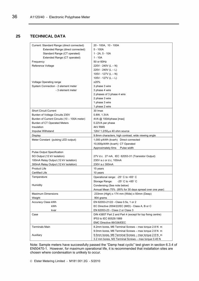
36 A1120/40 - Electronic Polyphase Meter
© Elster Metering Limited - M181 001 2G - 5/2010
25 TECHNICAL DATA
Current: Standard Range (direct connected) Extended Range (direct connected) Standard Range (CT operated) Extended Range (CT operated)
20 - 100A, 10 - 100A 5 - 100A 1 - 2A, 5 - 10A 1 - 10A
Frequency Reference Voltage Voltage Operating range System Connection - 2 element meter - 3 element meter
50 or 60Hz 220V - 240V (L – N) 220V - 240V (L – L) 105V - 127V (L – N) 105V - 127V (L – L) ±20% 3 phase 3 wire 3 phase 4 wire 2 phases of 3 phase 4 wire 2 phase 3 wire 1 phase 3 wire 1 phase 2 wire
Short Circuit Current Burden of Voltage Circuits 230V Burden of Current Circuits (10 – 100A meter) Burden of CT Operated Meters Insulation Impulse Withstand
30 Imax 0.8W, 1.3VA 4VA @ 100A/phase [max] 0.22VA per phase 4kV RMS 12kV 1.2/50μs 40 ohm source
Display 9.8mm characters, high contrast, wide viewing angle Meter Constant (pulsing LED output) 1,000 p/kWh (kvarh) Direct connected
10,000p/kWh (kvarh) CT Operated Approximately 6ms Pulse width
Pulse Output Specification SO Output (12 kV isolation) 100mA Relay Output (12 kV isolation) 300mA Relay Output (12 kV isolation)
27V d.c. 27 mA, IEC 62053-31 (Transistor Output) 230V a.c or d.c, 100mA 230V a.c 300mA
Product Life Certified Life
15 years 10 years
Temperature Humidity
Operational range: -25° C to +65° C Storage Range: -25° C to +85° C Condensing (See note below) Annual Mean 75% (95% for 30 days spread over one year)
Maximum Dimensions Weight
233mm (High) x 174 mm (Wide) x 50mm (Deep) 904 grams
Accuracy Class kWh kWh kvar
EN 62053-21/22 - Class 0.5s, 1 or 2 EC Directive 2004/22/EC (MID) - Class A, B or C EN 62053-23 - Class 2 or Class 3
Case DIN 43857 Part 2 and Part 4 (except for top fixing centre) IP53 to IEC 60529:1989 EMC Directive 89/336/EEC
Terminals Main Auxiliary
8.2mm bores, M6 Terminal Screws – max torque 2.8 N m 9.0mm bores, M6 Terminal Screws – max torque 2.8 N m 9.5mm bores, M6 Terminal Screws – max torque 2.8 N m 3.2 mm bores, M3 Terminal Screws – max torque 0.45 N
Note: Sample meters have successfully passed the “Damp heat cyclic” test given in section 6.3.4 of EN50470-1. However, for maximum operational life, it is recommended that installation sites are chosen where condensation is unlikely to occur.

Operating & Maintenance Instructions 37
26 INSTALLATION
26.1 Unpacking
Remove the meter from its packaging and inspect for damage.
Check that there is no movement or loose parts within the meter enclosure.
If damage has been sustained in transit, an immediate claim should be made to the Transport Company, and a report sent to the Elster Metering Systems branch office or agent.
WARNING
Removal of the main cover seals will invalidate certification.
The meter type and rating must be correct for the intended application.
26.2 Handling Once removed from the packaging, meters must be treated with care and not subjected to excessive shock or mechanical vibration.
Care should be taken to avoid marking or scratching the meter case and polycarbonate cover.
26.3 Storage If the meter is not required for immediate use, it should be returned to the original packing (including plastic bag) and stored in a clean, dry environment. Storage temperature: -25° C to +85° C
26.4 Installation Site The installation site should be a dry indoor environment and, as far as is practicable, away from direct sunlight and free from mechanical shock and vibration.
26.5 Electromagnetic Compatibility (EMC) The A1120/40 meter has been designed and tested for compliance with the EMC Directive.
It is, however, the responsibility of the installer for ensuring that a system conforms to the Directive.

38 A1120/40 - Electronic Polyphase Meter
© Elster Metering Limited - M181 001 2G - 5/2010
In order to assist the installer the following guidelines are given: - 1. Keep a.c. circuits and d.c. circuits separated by a minimum of 50mm where possible 2. Where a.c. and d.c. circuits must cross, do so at right angles to each other 3. The cables for each circuit must be bunched together to minimise the loop 4. area enclosed 5. The cables for the pulsing output must use a twisted pair. Where the environment is
electrically hostile, screened twisted pair cable may be required. The screen must be connected to earth at one point only
6. Ancillary equipment must also be CE marked 7. If interposing relays are used (a.c. or d.c.) then these must be correctly and adequately
suppressed
26.6 Fixing and Connection
WARNING
Installation must always be carried out by appropriately trained and qualified personnel in accordance with normal metering custom and practice.
The installer is responsible for the choice of connecting cables which must be appropriate for the voltage and current rating of the meter and for ensuring that the supply is properly fused. For direct current meters, 25mm2 cables are recommended. Meters must be protected by fuses equal to the meter rating. i.e. 100A fuse for a 100A meter. Failure to do so may result in damage or fire.
Connections to the auxiliary voltage terminals will only be protected by the installation’s main fuse cut-out. The installer must ensure that additional local protection is provided for any circuits connected to these terminals.
Refer to the connection diagrams inside the terminal cover, paying particular attention to the auxiliary terminal configuration.
Isolate all circuits before carrying out the installation.
Refer to the nameplate to ensure that the correct meter is being installed. Failure to comply with these instructions may result in damage, fire and/or electric shock.
To mount the meter on the meter board Remove the meter terminal cover.
Fix a 5mm dia. x 13mm long round headed wood screw into the meter board to accommodate the keyhole fixing aperture at the back of the meter. Note that a choice of two fixing points is available for the upper fixing screw (see figure 6). Leave the shank of the screw projecting from the board by 4.5 mm. Hang the meter on the screw and align it to be vertical. Secure the lower end of the meter to the board using two 5mm dia. x 13mm long round head screws through the lower mounting holes in the area of the terminal chamber. Tighten screws just sufficiently to prevent movement of the meter.

Operating & Maintenance Instructions 39
WARNING
Do not over-tighten the screws or the meter base may be damaged. For connecting to the large diameter terminals, strip back the cable insulation by 26mm.
Fully insert cables into the terminals so that the insulation butts up into the counter-sunk recesses in the bottom face of the terminal block.
Using a Number 2 Phillips or flat blade screwdriver, tighten the M6 terminal screws to a torque of between 2.2N m (minimum), 2.8N m (maximum).
Auxiliary terminal connections should be completed with appropriately sized cable. The M3 terminal screws should be tightened using a Number 1 Phillips or flat blade screwdriver to a maximum torque of 0.45N m.
Where connections are taken from the auxiliary voltage terminals, appropriate fuses should be incorporated to protect these circuits.
If a battery (for read without power) is installed in the module housing, the battery must be connected before mains supplies are energised.
It is also recommended that connections to the meter’s RJ11 connector are made with the meter supplies isolated.
27 COMMISSIONING
WARNING
Commissioning must only be carried out by appropriately trained and qualified personnel.
Check that the supply rating on the meter nameplate corresponds to the system rating.
Removal of the meter cover seals will invalidate certification.
With the system de-energised, check the cable connections are secure and correct to the wiring diagram fitted under the terminal cover
Refit and seal the terminal cover. Energise and load the system
At power-up, ensure all segments of the LCD show in the test pattern
Check that the display is cycling through the display sequence
Check that the LED test indicators are illuminated or flashing
Check the operation of the pulse output (if fitted)
Check operation of the RS232 port (if fitted)
Carry out load checks as necessary

40 A1120/40 - Electronic Polyphase Meter
© Elster Metering Limited - M181 001 2G - 5/2010
28 MAINTENANCE No maintenance is necessary during the meter's normal working life.
29 DISPOSAL AND RECYCLING Liquid Crystal Display Liquid crystals are toxic. If a display is damaged, avoid contact with the liquid. If the liquid makes contact with the skin it must be washed off immediately with water. Seek medical advice.
Recycling Materials The following meter materials are recyclable: polycarbonates, metals and printed circuit board (see Safety Warning in Section 2).
Major plastic parts are marked with recycling information. On the disposal of a meter, every endeavour should be made to comply with local environmental legislation regarding recovering materials and waste disposal.
Batteries
If the main cover is removed from the meter then a Lithium manganese dioxide battery will be exposed.
This battery is completely safe under normal conditions. However, it must never be disassembled, heated above 100°C, incinerated, nor have the contents exposed to water.
Fire, explosion or severe burns may result if these instructions are disregarded.
In the interests of safety, environmental protection and possible legislation, Lithium batteries require careful disposal.
Before arranging for the disposal of these cells, users should satisfy themselves that the proposed means of disposal is both safe and compliant with local legislation requirements.
Elster Metering Systems would like to draw the user's attention to the International Standard for Lithium Batteries - IEC 60084-4. - which gives further information about the handling, storage, transport and disposal of Lithium cells.
The user should contact Elster Metering Systems should difficulties arise in arranging proper disposal. They will if practical, help the user identify safe disposal means.
An optional battery may be housed in a module housing attached to the meter. The battery is a non re-chargeable, alkaline zinc manganese dioxide, PP3 size. Where local legislation places restraint on the disposal of this type of battery, the requirements of that legislation should be obeyed.

Operating & Maintenance Instructions 41
POLYPHASE (A1120/A1140) MODEL CODE
Vref Ib Imax MODEL
L-L L-N
TYPE (nameplate)
example: L M 3 A A B N N B B B N N B - A N
PRODUCT/TERMINATION Polyphase, BS/DIN termination L M SERVICE TYPE
3Ph 4W for use on: 3
3Ph 3W 2 CURRENT RANGE Direct Connected 20A – * (* is any multiple of Ib up to 100A maximum) A Direct Connected 10A – * (* is any multiple of Ib up to 100A maximum) B Direct Connected 5A – * (* is any multiple of Ib up to 100A maximum) C CT Operated 1A – 2A L CT Operated 5A – 10A M CT Operated 1A – 10A N Direct Connected (10A - 100A) -40 ْ to 70 ْC operation P VOLTAGE 220 - 240V (L - N) (See note 2 for Ref voltage ranges) A 220 - 240V (L - L) (See note 2 for Ref voltage ranges) (LM2****** variants only) B 105 - 127V (L - N) (See note 2 for Ref voltage ranges) Not OFGEM Approved C 105 - 127V (L - L) (See note 2 for Ref voltage ranges) (LM2****** variants only) Not OFGEM Approved D ACCURACY CLASS 50 Hz Cl.1 kWh, Cl.2 kvarh (IEC 62053-21, 23 see note 1) B 50 Hz Cl.2 kWh, Cl.3 kvarh (IEC 62053-21, 23 see note 1) C 60 Hz Cl.1 kWh, Cl.2 kvarh (IEC 62053-21, 23 see note 1) Not OFGEM Approved E 60 Hz Cl.2 kWh, Cl.3 kvarh (IEC 62053-21, 23 see note 1) Not OFGEM Approved F HARDWARE - SWITCHES No tamper detect switches N Two tamper detect switches B Terminal cover tamper detect switch and CT ratio programming protection switch C HARDWARE - BUTTONS No buttons N Two buttons B Backlit LCD with no buttons C Backlit LCD with twom buttons D HARDWARE - BATTERY No external battery connection N
External Battery connection. Note! External battery module cannot be fitted when an RS232 comms module is fitted B Supercapacitor/External battery/RS485 module connection C OPERATIONAL MODES Import kWh only B Import kWh, Q1 and Q4 kvarh C Import kWh, Q1, Q2, Q3, Q4 kvarh and Imp kVAh D Imp/Exp kWh E Imp/Exp kWh, Q1, Q2, Q3, and Q4 kvarh F Imp/Exp kWh and Imp/Exp kVAh G Imp/Exp kWh, Q1, Q2, Q3, Q4 kvarh and Imp/Exp kVAh H Import kWh only (Power Flow Insensitive) J Import kWh, Q1 and Q4 kvarh (Power Flow Insensitive) K Import kWh, Q1, Q2, Q3, Q4 kvarh and Imp kVAh (Power Flow Insensitive) L Import kWh only (Theft Resistant Measurement) R Import kWh, Q1 and Q4 kvarh (Theft Resistant Measurement) S Import kWh, Q1, Q2, Q3, Q4 kvarh and Imp kVAh (Theft Resistant Measurement) T TARIFFS A1120 Multi Rate B A1140 Multi Rate (with load profile) C A1120 Multi Rate with password protected register zeroing and zero level time shift D
A1140 (with load profile) Multi Rate with password protected register zeroing and zero level time shift E AUXILIARY OUTPUT No Output N
SO output, floating, 2 aux terminals. 12 kV isolation (Configurable pulse duration/value) 27V DA only P SO output, floating, 2 aux terminals. 12 kV isolation, replicating centre LED (kWh) 27V DA only A SO output, floating, 2 aux terminals. 12 kV isolation, replicating left hand LED (kvarh) 27V DA only R
Relay output, floating, 2 aux terminals. 12 kV isolation (Configurable pulse duration/value) 230V AC, DC S Relay output, floating, 2 aux terminals. 12 kV isolation, replicating centre LED (kWh) 230V AC, DC D Relay output, floating, 2 aux terminals. 12 kV isolation, replicating left hand LED (kvarh) 230V AC, DC U 300mA Relay output, floating, 2 aux terminals, 12kV isolation, indicating tariff/MD state, 230V a.c only T COMMUNICATIONS No Serial Comms N RS232 serial Comms Note! RS232 Comms module cannot be fitted when an external battery module is fitted R OTHER OPTIONS Standard (Extended) Terminal cover B Standard (Extended) Terminal cover with cut-out C Standard (Extended) Terminal plus 9.0mm main terminal bores D Short Terminal Cover E Standard (Extended) Terminal cover with additional voltage terminals F Standard (Extended) Terminal cover with cut-out and additional voltage terminals G Standard (Extended) Terminal cover plus 9.0 mm mail terminal bores and additional voltage terminals H Standard (Extended) Terminal cover plus 9.5 mm main terminal bores J Standard (Extended) Terminal cover and main cover with voltage disconnect protection K Standard (Extended) Terminal cover with slotted head screws L Standard (Extended) Terminal cover with cut-out and slotted head screws M Short terminal cover with slotted head screws P
Figure 1 - Model Code

42 A1120/40 - Electronic Polyphase Meter
© Elster Metering Limited - M181 001 2G - 5/2010
VERSION 8 TOU Registers, 4 MD Registers, 15 Historical Registers, DSM - see Note 4 - A 8 TOU Registers, 4 MD Registers, 15 Historical Registers, DSM, DLS time stamps and 12 external registers - Note! All new customers from November 2007 - see Note 4
- C
8 TOU Registers, 4 TOU Registers, 15 Historical Registers, DSM, DLS Time stamps, 12 External Registers and Daily Billing F 8 TOU Registers, 4 TOU Registers, 15 Historical Registers, DSM, DLS Time stamps, 12 External Registers - Note! Register zeroing by use of "Register Zeroing Tool" is NOT available in this option
G
Revision Suffix Firmware 2-01178-Q (Version A only). Enhanced GPRS and COP 10 QFirmware 2-01322-K (Version C) Enhanced GPRS and COP 10 K Firmware 2-01340-B (Version F) Daily Billing B Firmware 2-01345-A (Version G) Enhanced GPRS & COP 10. No register zeroing Z SPECIAL ADDITIONS FIRMWARE None NAdditional Firmware Function for ESCOM only (Phase angle definition as A1700 A SPECIAL ADDITIONS HARDWARE NONE N
Notes Note 1: CURRENT RATINGS
IEC/EN 62052-11 defines only Basic, Reference and Maximum currents as follows: Basic Current (Ib) Direct Connected Standard values: 5, 10, 15, 20, 30, 40, 50A Exceptional
values: 80A. Reference Current (In) CT Operated Standard values: 1, 2, 5A Exceptional values: 1.5, 2.5A Direct Connected Maximum current (Imax) shall preferably be an integral multiple of Ib.
Direct Connected A1120/A1140 meters may have Imax values up to a maximum of 100A CT Operated shall have maximum currents of 1.2 In, 1.5 In and 2 In
CT Operated A1120/A1140 meters may be:
1 - 2A (suitable for use as 1 - 1.2A, 1 - 1.5A, or 1 - 2A) 5 - 10A (suitable for use as 5 - 6A, 5 - 7.5A, or 5 - 10A) 1 - 10A (suitable for use with any of the above 6 ratings)
EN 50470-1 (MID) defines basic values or Itr from which Imin, Iref and Imax can be derived Basic values of Itr Direct Connected 0.5, 1, 1.5, 2A Basic values of Itr CT Operated 0.05, 0.1, 0.25 Imin, Iref and Imax have been chosen so that the following relationships are met Direct Connected, Class A Imin < 0.5 x Itr Iref = 10 x Itr Imax > 50 x Itr CT Operated, Class A Imin < 0.4 x Itr In = 20 x Itr Imax > 1.2 x In Direct Connected, Class B Imin < 0.5 x Itr Iref = 10 x Itr Imax > 50 x Itr CT Operated, Class B Imin < 0.2 x Itr In = 20 x Itr Imax > 1.2 x In
Note 2: VOLTAGE RATINGS
Of the values IEC/EN 62052-11 defines for reference voltages, the following may be accepted
Ref Voltages for meters not connected through current transformers Std values 120, 230, 400V Exceptional values 100, 127, 200, 220, 240, 380, 415V
EN 50470- 1 (MID) defines for reference voltages, the following standards and exceptional values
Ref Voltages for Direct Connected Std values 230/400V Exceptional values 220/380V, 240/415V
Meters with marked currents and voltages other than the above values CANNOT be provided when the nameplate shows the IEC/EN Standard Number.
If a valid requirement exists for meters with marked values within the acceptable ranges, but not listed above, specific arrangements to provide nameplates not showing the IEC/EN standard must be made. Note 3: TEST INDICATOR OUTPUT VALUES
The following values are to be used for the Test Indicator LED outputs: Direct Connected: 1,000 p/kWh (kvarh) CT Operated: 10,000 p/kWh (kvarh) Note 4: SCHEME COMPATIBILITY
Schemes generated for VERSION 'A' meters are not compatible with VERSION 'C' meters
Note 5: SPECIAL ADDITIONS Early issues of this code used the final (16th) digit for SPECIAL ADDITIONS and an 'A' in this position indicates "with additional voltage terminals".
Figure 1 - Model Code (Continued)

Operating & Maintenance Instructions 43
1. Reset Pushbutton 5. Display
2. Display Pushbutton 6. Nameplate
7. IEC 62056-21 Port
3. kvarh pulse LED
4. kWh pulse LED
1 Reset Pushbutton (See Section 15) 2 Display Pushbutton (See Section 15) 3 kvarh Pulse Indicator (See Section 9) 4 kWh Pulse Indicator (See Section 9) 5 Display (See Section 14) 6 Nameplate (See Figure 3) 7 IEC 62056-21 Port (See Section 16)
Module Carrier (Fits under the terminal cover) Figure 2 – A1120/40 Meter

44 A1120/40 - Electronic Polyphase Meter
© Elster Metering Limited - M181 001 2G - 5/2010
Figure 3 - Typical Nameplate

Operating & Maintenance Instructions 45
Figure 4 - Load Curves

46 A1120/40 - Electronic Polyphase Meter
© Elster Metering Limited - M181 001 2G - 5/2010
Terminal Block (3 phase 4 wire shown) Voltage connections Voltage Links shown in open position Main cover removal or CT ratio programming switch on a CT Meter. (whole current meters only) Terminal cover removal switch Optional additional
Voltage terminal on whole current meter
Molex connector to connect external battery
1 2 3 4 5 6 7 8 9 10 12 20 21 Element 1 Element 2 Element 3 Neutral Auxiliary Terminals RJ 11
RJ 11 and Auxiliary Terminals
Auxiliary Terminals
RJ11 Socket
6 5 4 3 2 1
Terminal & RJ11 Numbering
Terminal RJ11 1 2 3
Element 1 - Line in - Voltage terminal - Line out
4 5 6
Element 2 - Line In - Voltage Terminal - Line Out
1 2 3 4 5 6
Rx (Input) Tx (Output) Rx (Input) No Connection Zero Volts Modem Power Supply (+) Output
7 8 9
Element 3 - Line In - Voltage Terminal
- Line Out
10 12
Neutral In Neutral Out
Auxiliary 20 positive 21 negative
See Warning in Section 22 regarding protection for additional voltage terminals.
Figure 5 - Terminal Arrangements
Main cover with voltage disconnect protection. Note that this cover cannot be used if voltage terminals are fitted.

Operating & Maintenance Instructions 47
TO L
OADA
B
NC
+-
20 21
A
BC
JL 3
013
312B
LM3 ***
RxTx0V+V
3 phase 4 wire, CT operated
TO L
OADA
B
NC
+-
20 21
A
BC
JL 3
013
311B
LM3 ***
RxTx0V+V
3 phase 4 wire, Direct connected
Note: These diagrams are examples only.
WARNING
Meters must be connected according to the diagram fitted under the meter terminal cover.
Figure 5A – Terminal Configurations

48 A1120/40 - Electronic Polyphase Meter
© Elster Metering Limited - M181 001 2G - 5/2010
Back View Side View
171.5mm 49mm
139mm
121mm
233mm
150mm
110mm
Terminal Cover with Cut-out Short Terminal Cover Figure 6 – Dimensions, Fixing Centres

Operating & Maintenance Instructions 49
English Displays OBIS Displays
Segment Test
Cumulative
Customer Defined (1-2)
Rising Demand (Export)
Maximum Demand (1-4)
Maximum Demand (1-4) Date Time
Cumulative Maximum Demand (1-4)
Time of Use (1-8)
Figure 7 - A1120/40 Displays

50 A1120/40 - Electronic Polyphase Meter
© Elster Metering Limited - M181 001 2G - 5/2010
English Displays OBIS Displays Historical
Security (Reverse Run Event Count)
Instrumentation (Phase A Voltage)
Dial Test
Communications Indicators Optical Remote RS232
End of Billing (Change of Season) End of Billing (Internal Battery Fail)
Error (Power Fail Data) Error (Internal Battery Fail)
CT (Scalar) CT (Ratio)
External Registers
Figure 7 - A1120/40 Displays (continued)

Operating & Maintenance Instructions 51
Description Units OBIS Display Code English Display
Note 1 * Identifier Chevron Index Segment Test - - - - - Current Time - 0.9.1 - - - Current Date - 0.9.2 - - - Cumulative
Total Import kWh kWh 1.8.0 CUM 1 - Total Export kWh kWh 2.8.0 CUM 2 - Q1 kvarh kvarh 5.8.0 CUM - 1 Q2 kvarh kvarh 6.8.0 CUM - 2 Q3 kvarh kvarh 7.8.0 CUM - 3 Q4 kvarh kvarh 8.8.0 CUM - 4 kVAh 1 kVAh D.8.0 CUM - - kVAh 2 kVAh E.8.0 CUM - - Customer Defined 1 * A.8.0 CUM - Cd 1 Customer Defined 2 * B.8.0 CUM - Cd 2 Rising Demand Total Import kW kW 1.4.0 DEM 1 - Total Export kW kW 2.4.0 DEM 2 - Q1 kvar kvar 5.4.0 DEM - 1 Q2 kvar kvar 6.4.0 DEM - 2 Q3 kvar kvar 7.4.0 DEM - 3 Q4 kvar kvar 8.4.0 DEM - 4 kVA 1 kVA D.4.0 DEM - - kVA 2 kVA E.4.0 DEM - - CD 1 * A.4.0 DEM - Cd 1 CD 2 * B.4.0 DEM - Cd 2 Cumulative MD (1-4) Total Import kW kW 1.2.(1 - 4) CUM MAX DEM - 1 - 4 Total Export kW kW 2.2.(1 - 4) CUM MAX DEM - 1 - 4 Q1 kvar kvar 5.2.(1 - 4) CUM MAX DEM - 1 - 4 Q2 kvar kvar 6.2.(1 - 4) CUM MAX DEM - 1 - 4 Q3 kvar kvar 7.2.(1 - 4) CUM MAX DEM - 1 - 4 Q4 kvar kvar 8.2.(1 - 4) CUM MAX DEM - 1 - 4 kVA 1 kVA D.2.(1 - 4) CUM MAX DEM - 1 - 4 kVA 2 kVA E.2.(1 - 4 CUM MAX DEM - 1 - 4 1 - 4 CD 1 * A.2.(1 - 4) CUM MAX DEM - 1 - 4 1 - 4 CD 2 * B.2.(1 - 4) CUM MAX DEM - 1 - 4 Maximum Demand (1-4) 1 - 4 Import kW kW 1.6.(1 - 4) MAX DEM - 1 - 4 1 - 4 Import Time - 1.6.(1 - 4) MAX DEM - 1 - 4 1 - 4 Import Date - 1.6.(1 - 4) MAX DEM - 1 - 4 1 - 4 Export kW kW 2.6.(1 - 4) MAX DEM - 1 - 4 1 - 4 Export Time - 2.6.(1 - 4) MAX DEM - 1 - 4 1 - 4 Export Date - 2.6.(1 - 4) MAX DEM - 1 - 4 1 - 4 Q1 kvar kvar 5.6.(1 - 4) MAX DEM - 1 - 4 1 - 4 Q1 Time - 5.6.(1 - 4) MAX DEM - 1 - 4 1 - 4 Q1 Date - 5.6.(1 - 4) MAX DEM - 1 - 4 1 - 4 Q2 kvar kvar 6.6.(1 - 4) MAX DEM - 1 - 4 1 - 4 Q2 Time - 6.6.(1 - 4) MAX DEM - 1 - 4 1 - 4 Q2 Date - 6.6.(1 - 4) MAX DEM - 1 - 4 1 - 4 Q3 kvar kvar 7.6.(1 - 4) MAX DEM - 1 - 4 1 - 4 Q 3 Time - 7.6.(1 - 4) MAX DEM - 1 - 4 1 - 4 Q3 Date - 7.6.(1 - 4) MAX DEM - 1 - 4 1 - 4 Q4 kvar kvar 8.6.(1 - 4) MAX DEM - 1 - 4 1 - 4 Q4 Time - 8.6.(1 - 4) MAX DEM - 1 - 4 1 - 4 Q4 Date - 8.6.(1 - 4) MAX DEM - 1 - 4 1 - 4 kVA 1 kVA D.6.(1 - 4) MAX DEM - 1 - 4 1 - 4 kVA 1 Time - D.6.(1 - 4) MAX DEM - 1 - 4 1 - 4 kVA 1 Date - D.6.(1 - 4) MAX DEM - 1 - 4 1 - 4 kVA 2 kVA E.6.(1 - 4) MAX DEM - 1 - 4 1 - 4 kVA 2 Time - E.6.(1 - 4) MAX DEM - 1 - 4 1 - 4 kVA 2 Date - E.6.(1 - 4) MAX DEM - 1 - 4 1 - 4 CD 1 * A.6.(1 - 4) MAX DEM - 1 - 4 1 - 4 CD 1 Time * A.6.(1 - 4) MAX DEM - 1 - 4 1 - 4 CD 1 1 Date * A.6.(1 - 4) MAX DEM - 1 - 4 1 - 4 CD 2 * B.6.(1 - 4) MAX DEM - 1 - 4 1 - 4 CD 2 Time * B.6.(1 - 4) MAX DEM - 1 - 4 1 - 4 CD 2 Date * B.6.(1 - 4) MAX DEM - 1 - 4
Figure 8 - Display Table

52 A1120/40 - Electronic Polyphase Meter
© Elster Metering Limited - M181 001 2G - 5/2010
Description Units OBIS Display Code English Display
Note 1 Identifier Chevron Index TOU (1-8) 1 - 8 Import kWh kWh 1.8.(1 - 8) TOU - 1 - 8 1 - 8 Export kWh kWh 2.8.(1 - 8) TOU - 1 - 8 1 - 8 Q1 kvarh kvarh 5.8.(1 - 8) TOU - 1 - 8 1 - 8 Q2 kvarh kvarh 6.8.(1 - 8) TOU - 1 - 8 1 - 8 Q3 kvarh kvarh 7.8.(1 - 8) TOU - 1 - 8 1 - 8 Q4 kvarh kvarh 8.8.(1 - 8) TOU - 1 - 8 1 - 8 kVAh 1 kVAh D.8.(1 - 8) TOU - 1 - 8 1 - 8 kVAh 2 kVAh E.8.(1 - 8) TOU - 1 - 8 1 - 8 CD 1 * A.8.(1 - 8) TOU - 1 - 8 1 - 8 CD 2 * B.8.(1 - 8) TOU - 1 - 8 External Registers Register Set 1 (1-4) - User selectable Cum - S1 - (1 - 4) Register Set 2 (1-4) - User selectable Cum - S2 - (1 - 4) Register Set 3 (1-4) - User selectable Cum - S3 - (1 - 4) Security Program Event Count - C.2.0 - 4 1 Program Event Time - C.2.0 - 4 1 Program Event Date - C.2.0 - 4 1 CT Ratio Change Count - C.72.0 - 4 2 CT Ratio Change Time - C.72.0 - 4 2 CT Ratio Change Date - C.72.0 - 4 2 Phase Fail Event Count - C.54.0 - 4 3 Phase Fail Event Time - C.54.0 - 4 3 Phase Fail Event Date - C.54.0 - 4 3 Power Fail Event Count - C.7.0 - 4 4 Power Fail Event Time - C.7.0 - 4 4 Power Fail Event Date - C.7.0 - 4 4 Rev Run Event Count - C.53.0 - 4 5 Rev Run Event Time - C.53.0 - 4 5 Rev Run Event Date - C.53.0 - 4 5 End Billing Count - 0.1.0 - 4 7 End Billing Time - 0.9.6 - 4 7 End Billing Date - 0.9.7 - 4 7 Main Cov RemCount - C.70.0 - 4 8 Main Cov Remove Time - C.70.0 - 4 8 Main Cov Remove Date - C.70.0 - 4 8 Term Cov Rem Count - C.71.0 - 4 9 Term Cov Remove Time - C.71.0 - 4 9 Term Cov Remove Date - C.71.0 - 4 9 Est Battery Life Remain - C.6.0 - 4 10 In Service Hours - C.8.0 - 4 11 Active Tariff CRC - C.80.1 - 4 CrC1 Deferred Tariff CRC - C.80.4 - 4 CrC4 CT Ratio - 0.4.2 4 Ct
EOB Events (All Meters) Code (HEX) Display Program Date or Midnight 01 rESEt Change of Season 02 rESEt Deferred Tariff 04 rESEt Serial Port Command 08 rESEt Optical Port Command 10 rESEt Billing Pushbutton Press 20 rESEt CT Programming Event 40 rESEt Battery Fail 80 rESEt
Meter Errors - Power fail data - FF 0040 Error 0040 Period backup data error - FF 0080 Error 0080 ROM checksum error - FF 0100 Error 0100 I2C Bus error - FF 0200 Error 0200 Internal battery life exceeded
- FF 0400 Error 0400
Internal battery fail - FF 0800 Error 0800
Figure 8 - Display Table (continued)

Operating & Maintenance Instructions 53
Description Units OBIS Display Code English Display
Note 1 Identifier Chevron Index
Historical (Most recent only) Total Import kWh kWh 1.8.0.1 CUM - H1 Total Export kWh kWh 2.8.0.1 CUM - H1 Q1 kvarh kvarh 5.8.0.1 CUM - H1 Q2 kvarh kvarh 6.8.0.1 CUM - H1 Q3 kvarh kvarh 7.8.0.1 CUM - H1 Q4 kvarh kvarh 8.8.0.1 CUM - H1 Import kVAh kVAh D.8.0.1 CUM - H1 Export kVAh kVAh E.8.0.1 CUM - H1 Customer Defined 1 * A.8.0.1 CUM - H1 Customer Defined 2 * B.8.0.1 CUM - H1
Historical MD’s 1 - 4 Import kW kW 1.6.(1 - 4).1 MAX DEM - H1 (1 - 4) 1 - 4 Import Time - 1.6.(1 - 4).1 MAX DEM - H1 (1 - 4) 1 - 4 Import Date - 1.6.(1 - 4).1 MAX DEM - H1 (1 - 4) 1 - 4 Export kW kW 2.6.(1 - 4).1 MAX DEM - H1 (1 - 4) 1 - 4 Export Time - 2.6.(1 - 4).1 MAX DEM - H1 (1 - 4) 1 - 4 Export Date - 2.6.(1 - 4).1 MAX DEM - H1 (1 - 4) 1 - 4 Q1 kvar kvar 5.6.(1 - 4).1 MAX DEM - H1 (1 - 4) 1 - 4 Q1 Time - 5.6.(1 - 4).1 MAX DEM - H1 (1 - 4) 1 - 4 Q1 Date - 5.6.(1 - 4).1 MAX DEM - H1 (1 - 4) 1 - 4 Q2 kvar kvar 6.6.(1 - 4).1 MAX DEM - H1 (1 - 4) 1 - 4 Q2 Time - 6.6.(1 - 4).1 MAX DEM - H1 (1 - 4) 1 - 4 Q2 Date - 6.6.(1 - 4).1 MAX DEM - H1 (1 - 4) 1 - 4 Q3 kvar kvar 7.6.(1 - 4).1 MAX DEM - H1 (1 - 4) 1 - 4 Q 3 Time - 7.6.(1 - 4).1 MAX DEM - H1 (1 - 4) 1 - 4 Q3 Date - 7.6.(1 - 4).1 MAX DEM - H1 (1 - 4) 1 - 4 Q4 kvar kvar 8.6.(1 - 4).1 MAX DEM - H1 (1 - 4) 1 - 4 Q4 Time - 8.6.(1 - 4).1 MAX DEM - H1 (1 - 4) 1 - 4 Q4 Date - 8.6.(1 - 4).1 MAX DEM - H1 (1 - 4) 1 - 4 kVA 1 kVA D.6.(1 - 4).1 MAX DEM - H1 (1 - 4) 1 - 4 kVA 1 Time - D.6.(1 - 4).1 MAX DEM - H1 (1 - 4) 1 - 4 kVA 1 Date - D.6.(1 - 4).1 MAX DEM - H1 (1 - 4) 1 - 4 kVA 2 kVA E.6.(1 - 4).1 MAX DEM - H1 (1 - 4) 1 - 4 kVA 2 Time - E.6.(1 - 4).1 MAX DEM - H1 (1 - 4) 1 - 4 kVA 2 Date - E.6.(1 - 4).1 MAX DEM - H1 (1 - 4) 1 - 4 CD 1 * A.6.(1 - 4).1 MAX DEM - H1 (1 - 4) 1 - 4 CD 1 Time * A.6.(1 - 4).1 MAX DEM - H1 (1 - 4) 1 - 4 CD 1 Date * A.6.(1 - 4).1 MAX DEM - H1 (1 - 4) 1 - 4 CD 2 * B.6.(1 - 4).1 MAX DEM - H1 (1 - 4) 1 - 4 CD 2 Time * B.6.(1 - 4).1 MAX DEM - H1 (1 - 4) 1 - 4 CD 2 Date * B.6.(1 - 4).1 MAX DEM - H1 (1 - 4)
Historical Registers
CUM MD 1- 4 Import kW kW 1.2.(1 - 4).1 CUM MAX DEM - H1 (1 - 4) CUM MD 1 - 4 Export kW kW 2.2.(1 - 4).1 CUM MAX DEM - H1 (1 - 4) CUM MD Q1 1 - 4 kvar kvar 5.2.(1 - 4).1 CUM MAX DEM - H1 (1 - 4) CUM MD Q2 1 - 4 kvar kvar 6.2.(1 - 4).1 CUM MAX DEM - H1 (1 - 4) CUM MD Q3 1 - 4 kvar kvar 7.2.(1 - 4).1 CUM MAX DEM - H1 (1 - 4) CUM MD Q4 1 - 4 kvar kvar 8.2.(1 - 4).1 CUM MAX DEM - H1 (1 - 4) CUM MD kVA 1 1 - 4 kVA kVA D.2.(1 - 4).1 CUM MAX DEM - H1 (1 - 4) CUM MD kVA 2 1 - 4 kVA kVA E.2.(1 - 4) 1 CUM MAX DEM - H1 (1 - 4) CUM MD CD 1 1 - 4 * A.2.(1 - 4).1 CUM MAX DEM - H1 (1 - 4) CUM MD CD 2 1 - 4 * B.2.(1 - 4).1 CUM MAX DEM - H1 (1 -4) TOU 1 - 8 Import kWh kWh 1.8.(1 - 8).1 TOU - H1 (1 -8) TOU 1 - 8 Export kWh kWh 2.8.(1 - 8).1 TOU - H1 (1 - 8) TOU 1 - 8 Q1 kvarh kvarh 5.8.(1 - 8).1 TOU - H1 (1 - 8) TOU 1 - 8 Q2 kvarh kvarh 6.8.(1 - 8).1 TOU - H1 (1 - 8) TOU 1 - 8 Q3 kvarh kvarh 7.8.(1 - 8).1 TOU - H1 (1 - 8) TOU 1 - 8 Q4 kvarh kvarh 8.8.(1 - 8).1 TOU - H1 (1 - 8) TOU 1 - 8 kVAh 1 kVAh D.8.(1 - 8).1 TOU - H1 (1 - 8) TOU 1 - 8 kVAh 2 kVAh E.8.(1 - 8).1 TOU - H1 (1 - 8) TOU 1 - 8 CD 1 * A.8.(1 - 8).1 TOU - H1 (1 - 8) TOU 1 - 8 CD 2 * B.8.(1 - 8).1 TOU - H1 (1 - 8) Rev Run Count - C.53.0.1 - 4 H1 5 Phase Fail Count - C.54.0.1 - 4 H1 3 Power Fail Count - C.7.0.1 - 4 H1 4 Program Count - C.2.0.1 - 4 H1 1 CT Ratio Change Count - C.72.0.1 - 4 H1 2 Main Cover Remove Count - C.70.0.1 - 4 H1 8 Term Cover Remove Count - C.71.0.1 - 4 H1 9 End Billing Count - 0.1.0.1 - 4 H1 7 In Service Hours - C.8.0.1 - 4 H1 11 Estimated Battery Life - C.6.0.1 - 4 H1 10
Figure 8 - Display Table (continued)
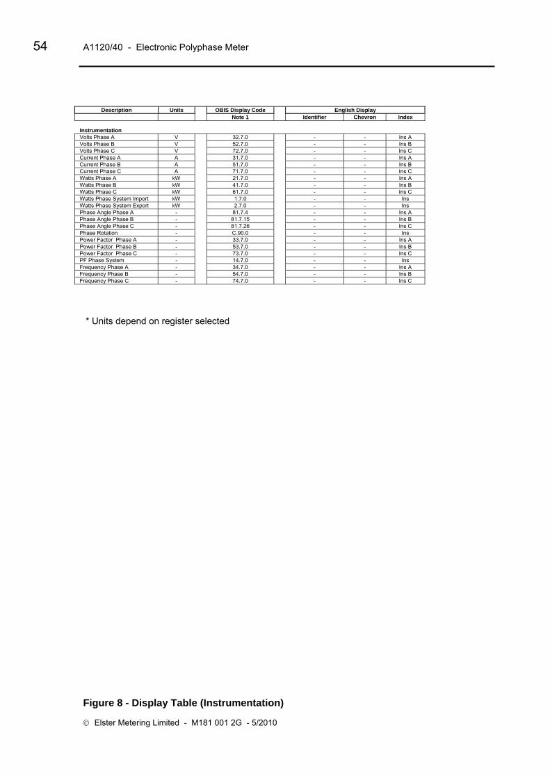
54 A1120/40 - Electronic Polyphase Meter
© Elster Metering Limited - M181 001 2G - 5/2010
Description Units OBIS Display Code English Display Note 1 Identifier Chevron Index
Instrumentation Volts Phase A V 32.7.0 - - Ins A Volts Phase B V 52.7.0 - - Ins B Volts Phase C V 72.7.0 - - Ins C Current Phase A A 31.7.0 - - Ins A Current Phase B A 51.7.0 - - Ins B Current Phase C A 71.7.0 - - Ins C Watts Phase A kW 21.7.0 - - Ins A Watts Phase B kW 41.7.0 - - Ins B Watts Phase C kW 61.7.0 - - Ins C Watts Phase System Import kW 1.7.0 - - Ins Watts Phase System Export kW 2.7.0 - - Ins Phase Angle Phase A - 81.7.4 - - Ins A Phase Angle Phase B - 81.7.15 - - Ins B Phase Angle Phase C - 81.7.26 - - Ins C Phase Rotation - C.90.0 - - Ins Power Factor Phase A - 33.7.0 - - Ins A Power Factor Phase B - 53.7.0 - - Ins B Power Factor Phase C - 73.7.0 - - Ins C PF Phase System - 14.7.0 - - Ins Frequency Phase A - 34.7.0 - - Ins A Frequency Phase B - 54.7.0 - - Ins B Frequency Phase C - 74.7.0 - - Ins C
* Units depend on register selected
Figure 8 - Display Table (Instrumentation)

Operating & Maintenance Instructions 55
Level 0 (Correct level 0 password [Read only])
Meter Serial Number
Meter Scheme Id
Level 1 (Correct level 1 password [Read only])
All data listed at level 0
Half hourly values of Load Profile
Total cumulative Active Energy
Total cumulative Reactive Energy
Total cumulative VA
Maximum Demand Registers (MD)
Time of Use Registers
Measurement transformer ratios
Measurement transformer error factor
Alarm indications
Level 2 (Correct level 2 password [Read and Program])
All data listed in level 0 and 1
Correction to the time and date
End of Billing
Time set
Level 3 (Correct level 3 password [Read and Program])
All operations listed in levels 0, 1 and 2
Programming
Setting the passwords for Levels 1, 2 and 3
Protocol Timeouts
Figure 9 – Password Access Levels
56 A1120/40 - Electronic Polyphase Meter
© Elster Metering Limited - M181 001 2G - 5/2010
APPENDIX A - Checking kWh and kvarh Registration Accuracy
WARNING
Only trained and competent personnel, familiar with meter test procedures should carry out the following operation.
A1 Introduction Various methods of checking the accuracy of registration of the A1120/40 meter are available. Methods using the LED test indicators and Register advances are described below.
A2 Checking Meter Accuracy Using the LED Test Indicator The LED test indicators are configured at manufacture to pulse for import kWh and import kvarh (import only meter) or pulse for import plus export kWh and kvarh (import/export or power flow insensitive meters).
A2.1 Comparing the number of LED pulses with substandard meter register advance
What you will need
Suitable test equipment with a sensor to detect LED pulses
A suitable substandard meter (set to the same system configuration as the meter under test)
A counter for counting the number of LED pulses
Checking registration
In order to achieve a repeatability of 0.1% the test time at any load needs to be a minimum of 60 seconds.
1. Connect the test equipment and a suitable load to the meter, then power up the meter
2. The right hand Test LED pulses for kWh
3. Run the test for a suitable duration and check the amount the substandard has advanced and the number of pulses detected
Calculate the registration by dividing the number of pulses by the meter constant.
e.g. 994 (LED count) = 0.994 kWh advance. 1000 (meter constant)
Compare this kWh advance with the amount the substandard has advanced.
Repeat for kvarh using left hand Test LED.
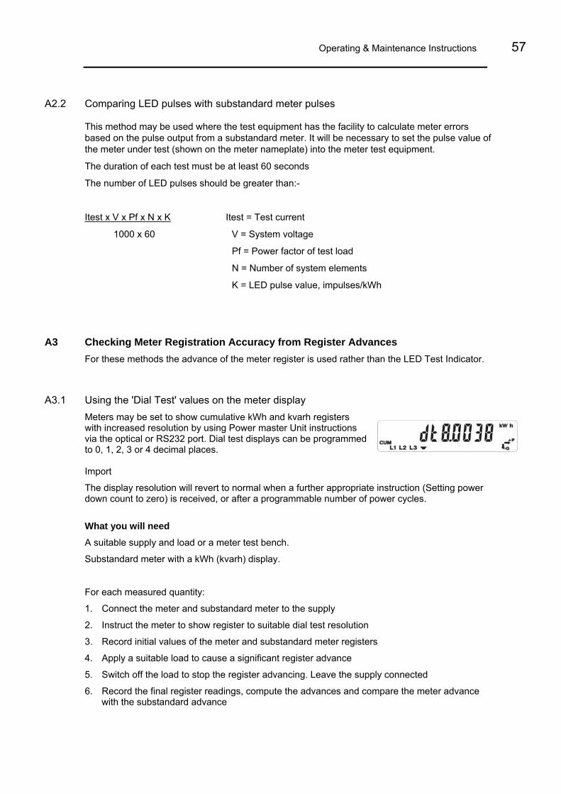
Operating & Maintenance Instructions 57
A2.2 Comparing LED pulses with substandard meter pulses
This method may be used where the test equipment has the facility to calculate meter errors based on the pulse output from a substandard meter. It will be necessary to set the pulse value of the meter under test (shown on the meter nameplate) into the meter test equipment.
The duration of each test must be at least 60 seconds
The number of LED pulses should be greater than:-
Itest x V x Pf x N x K Itest = Test current
1000 x 60 V = System voltage
Pf = Power factor of test load
N = Number of system elements
K = LED pulse value, impulses/kWh
A3 Checking Meter Registration Accuracy from Register Advances For these methods the advance of the meter register is used rather than the LED Test Indicator.
A3.1 Using the 'Dial Test' values on the meter display Meters may be set to show cumulative kWh and kvarh registers with increased resolution by using Power master Unit instructions via the optical or RS232 port. Dial test displays can be programmed to 0, 1, 2, 3 or 4 decimal places. Import
The display resolution will revert to normal when a further appropriate instruction (Setting power down count to zero) is received, or after a programmable number of power cycles.
What you will need
A suitable supply and load or a meter test bench.
Substandard meter with a kWh (kvarh) display.
For each measured quantity:
1. Connect the meter and substandard meter to the supply
2. Instruct the meter to show register to suitable dial test resolution
3. Record initial values of the meter and substandard meter registers
4. Apply a suitable load to cause a significant register advance
5. Switch off the load to stop the register advancing. Leave the supply connected
6. Record the final register readings, compute the advances and compare the meter advance with the substandard advance

58 A1120/40 - Electronic Polyphase Meter
© Elster Metering Limited - M181 001 2G - 5/2010
APPENDIX B - RS232 Multi-drop Mode A1120/40 meters allow up to 12 meters to be connected in RS232 multi-drop configuration. Two-way RJ11 adaptors will be required to link each meter in the chain.
B1 RS232 Multi-drop Installation Procedure
The connection diagram for RS232 multi-drop mode is shown below
1. Observe all Safety Warnings, Warnings, Precautions for handling electrostatic discharge sensitive devices and EMC Guidelines in Section 2
2. Remove the terminal cover from the meters. If the terminal cover plate is not in place, switch off all supplies to the meter.
3. Connect a two-way RJ11 adaptor to the RJ11 port of the first meter in the multi-drop chain
4. Connect an RS232 cable from the PC to the first port of the RJ11 as shown below
5. Connect a Flat Pin Cable to the second port of the RJ11 adaptor
6. Replace the terminal cover and fit appropriate seals
7. Connect a two-way RJ11 adaptor to the RJ11 port of the second meter in the multi-drop chain
8. Connect the flat pin cable from the first meter to the RJ11 adaptor of the second meter in the multi-drop chain
9. Connect a Flat Pin Cable to the second port of the RJ11 adaptor
10. Replace the terminal cover and fit appropriate seals
11. Continue as steps 7 to 10 to the next meter
12. When all multi-drop connections are made and all terminal covers are in place, switch on the supplies
R 11 AdaptorJ R 11 AdaptorJ
Next MeterFrom PC Flat Pin Cable
Rx (2)Tx (3)
No Connection (4)Zero Volts (5)
(2) Tx(3) Rx(4)(5)
RJ11 Connector
6 5 4 3 2 1

Operating & Maintenance Instructions 59
APPENDIX C - RS485 Multi-drop Mode A1120/40 meters allow up to 12 meters to be connected in RS485 multi-drop configuration. Two-way RJ11 adaptors will be required to link each meter in the chain.
Amplicon Amplicon Amplicon8 7 6 5 4 3 2 1 8 7 6 5 4 3 2 1 8 7 6 5 4 3 2 1
25-way D type 25-way D type 25-way D type
+VDC 7 4 2 3 +VDC 7 4 2 3
6 5 4 3 2 1 6 5 4 3 2 1
RJ11 RJ11
W
hite
W
hite
B
lack
Bla
ck
Y
ello
w
Yello
w
B
lue
B
lue
Next Meter
1: 2: 3: B4: A5: A16: B17: VCD8: Gnd
Gnd+V
PC Standard 9-25 Way Lead

60 A1120/40 - Electronic Polyphase Meter
© Elster Metering Limited - M181 001 2G - 5/2010
APPENDIX D - External Battery Module
D1 External Battery Module
An External Battery Module can be fitted as an option which allows reading of meter data via the optical port and access to the display facilities during power outages. The battery is housed in the Module Carrier that fits below the meter terminal cover.
The Battery Module connects to the meter via a special ‘Molex’ connector.
The 'Molex' connector is optional. The use of the External Battery Module must be specified at the time the meters are ordered.
External Battery Status The battery voltage is monitored to detect if it has failed. A new battery install date can be programmed and can be read back from the meter.
Using the External Battery Facility during Power Outages The External Battery facility will only operate when power has been removed from the meter. The module is energised by pressing the display pushbutton.
Once the module has been energised-
Displays can cycled in the normal way using the pushbuttons Meter data can be read via the optical port (note that the communications session will always be completed before power is removed)
External Battery Module power will be removed from the meter if the 'No button time-out' (programmable from 10 to 120 seconds using the Power Master Unit) has expired.

Operating & Maintenance Instructions 61
D2 Installation
WARNINGS
Read Section 2 (Warnings) before installing the Battery Module.
Check that the terminal cover plate is in place before installing the module. If the terminal cover plate is not in place, all supplies to the meter must be isolated.
For correctly installed 3 phase 4 wire meters, one of the battery connections will be at 'Mains Neutral' potential. Under fault conditions, this connection could be raised to a 'Fatally Dangerous Potential'.
For 3 phase 3 wire meters, one of the battery connections will be at 'Mains Phase Potential'.
The External Battery Module and its connection leads are double insulated. No attempt should be made to modify the assembly or open the module housing. A replacement assembly must be used if the battery becomes exhausted.
Failure to follow these instructions may result in electric shock or death.
Installing the Module
1. Read the Warnings above
2. Remove the meter terminal cover
3. If the terminal cover plate is not in place, do not attempt to install the module unless all supplies to the meter have been isolated
4. Clip the Battery Module over the Terminal Block as shown in Section D1
5. Connect the 'Polarised Molex connector' to the 'Molex socket' making sure the cable is routed in the recess by the 'Terminal Block Screw Holder' as shown in Section D1
6. Replace the terminal cover
Technical Information
Battery Type (Alkaline zinc manganese dioxide) +9 Volt PP3 (IEC 6LR61)
Battery Life 5 years with one reading session each month
Battery Safety See Warnings, Section 2
Specifications 550 mA hours


A1120/40 Programmable Electronic Polyphase Meter
Chapter 4 - Communications
M181 001 4A
5.2007
DRAFT
Other Manuals in this Series
A1120/40 Operating & Maintenance M181 001 2 A1120/40 Software Support M181 001 4

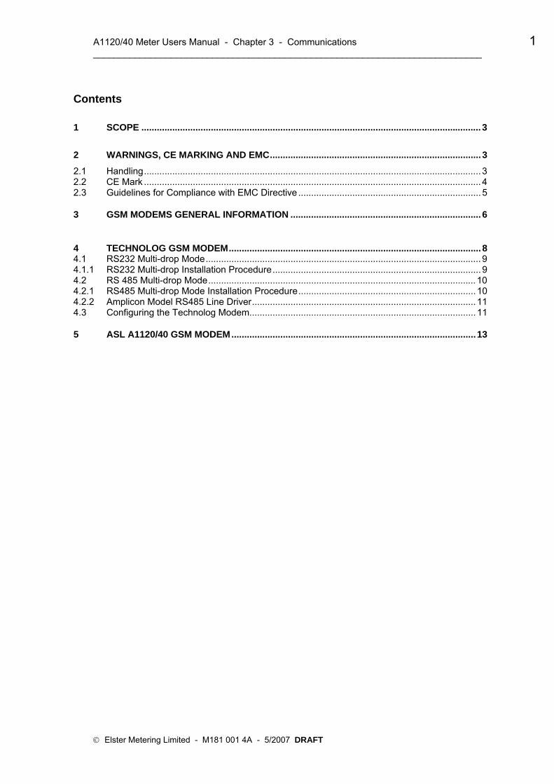
A1120/40 Meter Users Manual - Chapter 3 - Communications 1 ___________________________________________________________________________
Contents
1 SCOPE .................................................................................................................................... 3
2 WARNINGS, CE MARKING AND EMC.................................................................................. 3
2.1 Handling................................................................................................................................... 3 2.2 CE Mark ................................................................................................................................... 4 2.3 Guidelines for Compliance with EMC Directive ....................................................................... 5
3 GSM MODEMS GENERAL INFORMATION .......................................................................... 6
4 TECHNOLOG GSM MODEM.................................................................................................. 8 4.1 RS232 Multi-drop Mode........................................................................................................... 9 4.1.1 RS232 Multi-drop Installation Procedure................................................................................. 9 4.2 RS 485 Multi-drop Mode........................................................................................................10 4.2.1 RS485 Multi-drop Mode Installation Procedure.....................................................................10 4.2.2 Amplicon Model RS485 Line Driver.......................................................................................11 4.3 Configuring the Technolog Modem........................................................................................11
5 ASL A1120/40 GSM MODEM...............................................................................................13
© Elster Metering Limited - M181 001 4A - 5/2007 DRAFT

2 A1120/40 Users Manual - Chapter 3 __________________________________________________________________________
FORWARD
HEALTH AND SAFETY WARNING
Compliance with Instructions in this Manual
The instructions and information in this manual are provided in compliance with Section 6 of the UK Health and Safety at Work Act, as amended by Schedule 3 of the Consumer Protection Act 1987. The purchaser is responsible for making sure that everyone, whether in his employment or not, who will be associated with the products supplied by Elster Metering Systems, and to which these instructions and information apply, are made familiar with the contents of this manual.
This applies to all persons who may be involved in activities such as unpacking, inspecting, testing, setting, cleaning, installing, commissioning, operating, maintaining, decommissioning or disposing of the products.
Safety of Persons using Electrical Products
Employers are reminded that they have a duty to ensure, as far as is reasonably practicable, the Health, Safety and Welfare at work of all their Employees. Employers must therefore ensure that employees are informed; trained and supervised and use proper working procedures to ensure the safety of themselves and others.
The information provided in this manual is intended to ensure that products are properly installed and otherwise handled in order to maintain them in a safe condition.
In the UK, employers have duties under the Health and Safety at Work Act 1974 and the various regulations stemming therefrom.
In countries outside the UK, employers should ensure proper compliance with the Health and Safety Legislation which is applicable to them.
Putting into Service
Products supplied by Elster Metering Systems have been designed and manufactured, in accordance with appropriate standards, to operate under specified conditions, when properly installed. The purchaser or delegated contractor is responsible for the "Putting into Service" of any Elster Metering Systems products which have been supplied as "Non-connected".
All related activities must therefore be carried out with due regard to any applicable legislation, standards and good practice.
© Elster Metering Limited - M181 001 4A - 5/2007 DRAFT

Communications 3 ___________________________________________________________________________
Communications
1 SCOPE
This Chapter covers the operation and installation of the ASL A1120/40 GSM modem and Technolog A1120/40 GSM modem. Both modems are housed in a secure carrier that fits under the meter terminal cover.
Before installing a module or module peripheral equipment, read the Safety Warnings, Warnings, Precautions for handling electrostatic discharge sensitive devices and EMC Guidelines below.
2 WARNINGS, CE MARKING AND EMC
SAFETY WARNINGS
Dangerous voltages are present
If the Terminal Cover Plate is not fitted to the A1120 meter, all supplies to the meter must be isolated before a module or module peripheral equipment is installed or removed.
Failure to do so may result in electric shock or death.
When installing or removing a module, be aware that multi-drop terminals may be energised from other A1120 meters.
Caution
Installation of a faulty module or module peripheral equipment may affect the main meter functionality.
2.1 Handling
CAUTION
Observe precautions for handling electrostatic discharge sensitive devices
When handling communications modules and module peripheral equipment described in this manual, observe electrostatic discharge precautions at all times.
Avoid touching connector pins and printed circuit boards on communications modules and module peripheral equipment where the PCB is exposed.
Failure to adhere to this instruction may result in electrostatic damage, contamination or corrosion.
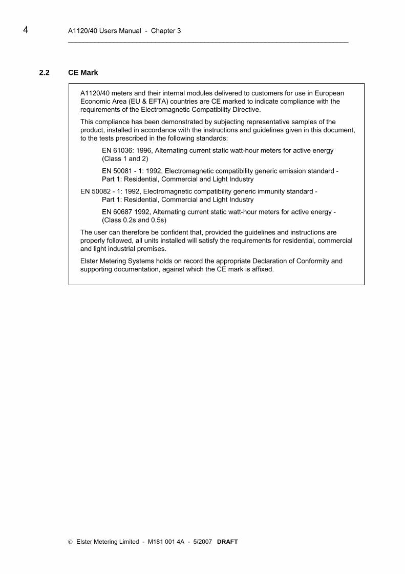
4 A1120/40 Users Manual - Chapter 3 __________________________________________________________________________
2.2 CE Mark
A1120/40 meters and their internal modules delivered to customers for use in European Economic Area (EU & EFTA) countries are CE marked to indicate compliance with the requirements of the Electromagnetic Compatibility Directive.
This compliance has been demonstrated by subjecting representative samples of the product, installed in accordance with the instructions and guidelines given in this document, to the tests prescribed in the following standards:
EN 61036: 1996, Alternating current static watt-hour meters for active energy (Class 1 and 2)
EN 50081 - 1: 1992, Electromagnetic compatibility generic emission standard - Part 1: Residential, Commercial and Light Industry
EN 50082 - 1: 1992, Electromagnetic compatibility generic immunity standard - Part 1: Residential, Commercial and Light Industry
EN 60687 1992, Alternating current static watt-hour meters for active energy - (Class 0.2s and 0.5s)
The user can therefore be confident that, provided the guidelines and instructions are properly followed, all units installed will satisfy the requirements for residential, commercial and light industrial premises.
Elster Metering Systems holds on record the appropriate Declaration of Conformity and supporting documentation, against which the CE mark is affixed.
© Elster Metering Limited - M181 001 4A - 5/2007 DRAFT
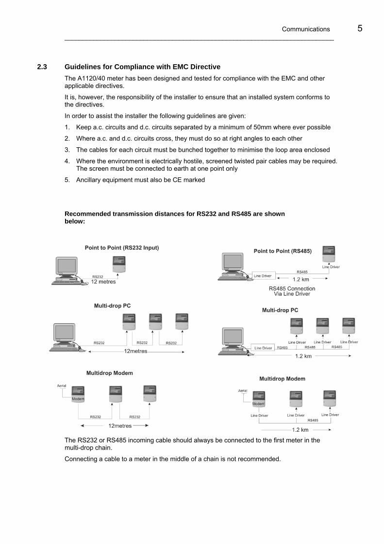
Communications 5 ___________________________________________________________________________
2.3 Guidelines for Compliance with EMC Directive
The A1120/40 meter has been designed and tested for compliance with the EMC and other applicable directives.
It is, however, the responsibility of the installer to ensure that an installed system conforms to the directives.
In order to assist the installer the following guidelines are given:
1. Keep a.c. circuits and d.c. circuits separated by a minimum of 50mm where ever possible
2. Where a.c. and d.c. circuits cross, they must do so at right angles to each other
3. The cables for each circuit must be bunched together to minimise the loop area enclosed
4. Where the environment is electrically hostile, screened twisted pair cables may be required. The screen must be connected to earth at one point only
5. Ancillary equipment must also be CE marked
Recommended transmission distances for RS232 and RS485 are shown below:
The RS232 or RS485 incoming cable should always be connected to the first meter in the multi-drop chain.
Connecting a cable to a meter in the middle of a chain is not recommended.

6 A1120/40 Users Manual - Chapter 3 __________________________________________________________________________
3 GSM MODEMS GENERAL INFORMATION GSM (Global System for Mobile) Communications Modems are ideally suited for use in remote areas where it is not practical to connect to a PSTN telephone network. The modems can be used in any area that provides GSM coverage.
Two types of GSM modems have been developed for use with the A1120/40 meter:
Technolog A1120/40 GSM Cello Modem
ASL A1120/40 GSM Modem
The modems have been custom designed for use with the A1120/40 meter and can be installed beneath the meter terminal cover.
GSM modems can be used with the Service provider of your choice.
Meters can be multi-dropped if required (See Section 4.2.1 for multi-drop Installation).
About the SIM
The SIM Card must be provided by the by the Network Service Provider (O2, Orange, Vodafone etc) with the following settings:
Data enabled Air baud rate: 1200 - 9600 (the SIM baud rate must be configured to match the meter serial port baud rate)
Transparent (no error correction) or non-transparent (error correction)
The preferred settings for the A1120 are - 9600 baud, non-transparent
SIM security pin disable
It is a requirement that the SIM Card Pin Security Number for all types of GSM modem is disabled on installation. If the pin security number is enabled and the modem is powered down, a site visit will be necessary to re-enter the pin number.
Transmission speeds (all modems)
1200 baud 2400 baud 4800 baud 9600 baud
Error checking
The GSM system allows full verification of all data received when configured in non-transparent mode.
Antenna There is a wide range of antennae, each with their own characteristics for use with GSM modems. It is therefore important to choose an antenna most suitable for your installation.
© Elster Metering Limited - M181 001 4A - 5/2007 DRAFT

Communications 7 ___________________________________________________________________________
How to Site the Antenna
The antenna should be mounted vertically in a position where it is possible to receive good mobile phone reception from your Service Provider. Signal strength may be tested by using the monitor on a mobile telephone providing the mobile uses the same service provider as the SIM in the GSM.
It is recommended that the antenna is mounted at least 1 metre from the installation.

8 A1120/40 Users Manual - Chapter 3 __________________________________________________________________________
4 TECHNOLOG GSM MODEM Features
• Dual-band (900/1800 MHz) • 1200 to 9600 baud rate • RS232 port • Transparent or non-transparent mode • Fully compliant with ETSI GSM Phase 2+
specifications (Normal MS) • Tri-coloured LED indicating modem status and signal
strength • Software reset facility • 10 years design life • Over the air programmable • Powered from meter • Power 500mA at 5V (min)
Automatic Reset Facility
An automatic reset is initiated to unlock a locked modem.
Connecting the Modem in Multi-drop Mode
Up to 10 meters (RS232) or 32 meters (RS485) can be connected in multi-drop mode.
For RS232 connection, see Section 4.1.
For RS485 connection, see Section 4.2
What You Will Need
Equipment Description
GSM Modem Technolog or ASL
SIM Card (Supplied by Service Provider)
Antenna and Cable
To suit application
Midi Mag 3db GSM 4m SMA (Example)
RS232 two-way Adaptor(s)
Amplicon Line Driver(s) Model 485
Note: There is a wide variety of equipment meeting the required specifications available for use with Elster GSM modems. Equipment listed is a representative sample only.
© Elster Metering Limited - M181 001 4A - 5/2007 DRAFT

Communications 9 ___________________________________________________________________________
4.1 RS232 Multi-drop Mode Up to 10 meters can be connected in multi-drop configuration from a single modem. The maximum transmission distance is 12 metres. Each meter will require a two-way RJ11 adaptor to link to the next meter in the chain.
4.1.1 RS232 Multi-drop Installation Procedure The connection diagram for RS232 multi-drop mode is shown below.
Each meter in the chain will require an RJ11 two-way adaptor.
1. Observe all Safety Warnings, Warnings, Precautions for handling electrostatic discharge sensitive devices and EMC Guidelines in Section 2
2. Remove the terminal cover from the meters. If the terminal cover plate is not in place, switch off all supplies to the meter.
3. Connect a two-way RJ11 adaptor to the RJ11 port of the first meter in the multi-drop chain
4. Connect the modem to the first port of the adaptor
5. Connect a Flat Pin Cable to the second port of the RJ11 adaptor
6. Replace the terminal cover and fit appropriate seals
7. Connect a two-way RJ11 adaptor to the RJ11 port of the second meter in the multi-drop chain
8. Connect the flat pin cable from the first meter to the RJ11 adaptor of the second meter in the multi-drop chain
9. Connect a Flat Pin Cable to the second port of the RJ11 adaptor
10. Replace the terminal cover and fit appropriate seals
11. Continue as steps 7 to 10 to the next meter
12. When all multi-drop connections are made and all terminal covers are in place, switch on the supplies
R 11 AdaptorJ
Next MeterFlat 4-Pin Cable
R 11 AdaptorJ
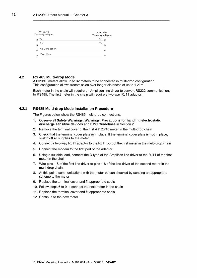
10 A1120/40 Users Manual - Chapter 3 __________________________________________________________________________
A1120/40Two-way adaptor
A1120/40Two-way adaptor
2
3
4
5
2
3
4
5
Tx
TxRx
Rx
Zero Volts
No Connection
4.2 RS 485 Multi-drop Mode A1120/40 meters allow up to 32 meters to be connected in multi-drop configuration. This configuration allows transmission over longer distances of up to 1.2km.
Each meter in the chain will require an Amplicon line driver to convert RS232 communications to RS485. The first meter in the chain will require a two-way RJ11 adaptor.
4.2.1 RS485 Multi-drop Mode Installation Procedure The Figures below show the RS485 multi-drop connections.
1. Observe all Safety Warnings, Warnings, Precautions for handling electrostatic discharge sensitive devices and EMC Guidelines in Section 2
2. Remove the terminal cover of the first A1120/40 meter in the multi-drop chain 3. Check that the terminal cover plate is in place. If the terminal cover plate is not in place,
switch off all supplies to the meter 4. Connect a two-way RJ11 adaptor to the RJ11 port of the first meter in the multi-drop chain
5. Connect the modem to the first port of the adaptor
6. Using a suitable lead, connect the D type of the Amplicon line driver to the RJ11 of the first meter in the chain
7. Wire pins 1-8 of the first line driver to pins 1-8 of the line driver of the second meter in the multi-drop chain.
8. At this point, communications with the meter be can checked by sending an appropriate scheme to the meter
9. Replace the terminal cover and fit appropriate seals 10. Follow steps 6 to 9 to connect the next meter in the chain 11. Replace the terminal cover and fit appropriate seals 12. Continue to the next meter
© Elster Metering Limited - M181 001 4A - 5/2007 DRAFT

Communications 11 ___________________________________________________________________________
Amplicon Amplicon Amplicon8 7 6 5 4 3 2 1 8 7 6 5 4 3 2 1 8 7 6 5 4 3 2 1
25-way D type 25-way D type 25-way D type
+VDC 7 4 2 3 +VDC 7 4 2 3 +VDC 7 4 2 3
6 5 4 3 2 1 6 5 4 3 2 1 6 5 4 3 2 1
Two-way R 11 adaptorJ
RJ11 RJ11
W
hite
W
hite
W
hite
B
lack
B
lack
B
lack
Yello
w
Y
ello
w
Y
ello
w
B
lue
B
lue
B
lue
Next Meter
1: 2: 3: B4: A5: A16: B17: 8:
4.2.2 Amplicon Model RS485 Line Driver The Amplicon line driver converts RS232 transmission to RS485 This configuration allows transmission over longer distances of up to 1.2km.
4.3 Configuring the Technolog Modem The Technolog modem communications parameters can be configured using an SMS text message via a mobile phone.
The initial settings will depend on whether the meter is configured for a Standard Data to Read or Data Stream Mode.
Standard Data to Read Mode Data Stream Mode
Enter Bits Per Second = 9600 Enter Bits Per Second = 9600
Data Bits = 7 Data Bits = 8
Parity = E Parity = None
Stop Bits = 1 Stop Bits = 1
Flow Control = None Flow Control = None
Inserting the SIM
The SIM should be set to the Service Provider settings detailed in Section C2, General Information (About the SIM).
SIM Card Type
Carefully slide the SIM into the SIM slot

12 A1120/40 Users Manual - Chapter 3 __________________________________________________________________________
Modem Settings
Set up an SMS text message on your mobile phone as follows:
ZT1xyz Where x is the baud rate 0 - 1200 1 - 2400 2 - 4800
3 - 9600
Where y is the parity 0 - Even 1 - Odd 2 - None
Where z is the data bits 0 - 7
1 - 8 Send the text message to the data number of the SIM Card
© Elster Metering Limited - M181 001 4A - 5/2007 DRAFT

Communications 13 ___________________________________________________________________________
5 ASL A1120/40 GSM MODEM Features • Modem compatible communications rates up to 9600
baud • Error correction including V110 (for ISDN/GSM
connected host • IP connectivity for AMR using low cost GPRS services • SMS AMR capability with programmable read time
and remote diagnostics • Industry standard RJ12 plug interface flying lead • Host powered • LED indication for modem status, network status and signal strength • Standby mode with current drain of 50mW • Typical average operating power of <500mW • Local or remote antenna • RS232/RS485 multi-drop option Modem Installation The modem connects to the meter in exactly the same way as the Technolog modem by using standard At Hayes commands The ASL modem communications parameters can be configured using an SMS text message via a mobile phone.
The initial settings will depend on whether the meter is configured for a Standard Data to Read or Data Stream Mode.
Standard Data to Read Mode Data Stream Mode
Enter Bits Per Second = 9600 Enter Bits Per Second = 9600
Data Bits = 7 Data Bits = 8
Parity = E Parity = None
Stop Bits = 1 Stop Bits = 1
Flow Control = None Flow Control = None
Inserting the SIM
The SIM should be set to the Service Provider settings detailed in Section C2, General Information (About the SIM).
SIM Card Type
Carefully slide the SIM into the SIM slot

14 A1120/40 Users Manual - Chapter 3 __________________________________________________________________________
Configuring the Modem
1. Connect a PC with HyperTerminal installed to the modem
2. Open the HyperTerminal software. Type the name of the connection in the field provided
3. Press OK
4. The dialogue opposite is displayed
5. Select the PC Port to which the GSM modem is connected
6. Press OK
7. Enter the modem settings shown below
8. Disconnect the power
Modem Settings for ASL GSM Modem Type the following commands to configure the modem:
ATQ0 <ENTER> Quite mode off
ATE1 “ Echo on
AT&C1 " Indicates remote carrier
AT&D0 " Ignore DTR
ATS0 = 1 " Answer after 1 ring
ATS10 = 50 " Comms timeout
AT+CBST = 7,0,1 " (These settings should be set by your service provider). [Speed], [Name], [Connection Element]
AT+0 Speed 9600 N81 AT+1 9600 E71 AT+2 4800 N81 AT+3 4800 E71 AT+5 2400 N81 AT+6 2400 E71 AT+7 1200 N81 1200 E71
Once configured, remember to change HyperTerminal baud rate to match.
ATE0 <ENTER> Echo off ATQ1 " Suppress result codes AT&W " Save settings AT&V " View modem settings
© Elster Metering Limited - M181 001 4A - 5/2007 DRAFT

Communications 15 ___________________________________________________________________________
LED Status Indicators
The ASL modem has three status LED’s
Modem Status (Green LED)
Slow flash (once every 3 seconds) CDS mode (waiting for call) Fast flash (twice a second) during call
Network status (Red LED)
Off (module off)
On (Not registered) Long pauses, short blinks (Registered with network)
Signal strength (Yellow LED)
Off/ Slow flash/ On (with increasing signal levels) (The more ‘on time’ the better the signal)

16 A1120/40 Users Manual - Chapter 3 __________________________________________________________________________
© Elster Metering Limited - M181 001 4A - 5/2007 DRAFT

A1120/40 Programmable Electronic Polyphase Meter
Chapter 3 - Software Support
M181 001 3C 12.2007
Other Manuals in this Series
A1120/40 Operating & Maintenance Instructions M181 001 2
A1120/40 Communications M181 001 4


A1120/1140 Programmable Polyphase Meter Users Manual - Chapter 4 i __________________________________________________________________ CONTENTS POWER MASTER UNIT METER COMPATIBILITY ............................................................................... III SOFTWARE INSTALLATION ............................................................................................................IV
POWER MASTER UNIT ........................................................................................................... 1
1.1 POWER MASTER UNIT INTRODUCTION ........................................................................... 1 1.2 PREREQUISITES............................................................................................................ 1 1.3 LOGGING ON TO THE SYSTEM ....................................................................................... 2 1.4 FEATURES OF THE MAIN MASTER UNIT WINDOW............................................................ 2 Action Windows.......................................................................................................... 2 1.5 THE MAIN WINDOW ...................................................................................................... 3 Menus......................................................................................................................... 4 Scheme Editor Pages ................................................................................................ 6 Using the Toolbar ....................................................................................................... 7 About Help.................................................................................................................. 7
THE SCHEME MANAGER ....................................................................................................... 9
2.1 INTRODUCING SCHEMES ............................................................................................... 9 2.2 THE SCHEME MANAGER COMPONENTS ......................................................................... 9 2.3 SCHEME MANAGER..................................................................................................... 10
SCHEME EDITOR................................................................................................................... 11
3.1 SELECTING THE METER TYPE...................................................................................... 11 3.2 SCHEME EDITOR ........................................................................................................ 11 3.3 STARTING A NEW SCHEME.......................................................................................... 12 3.4 SCHEME EDITOR ........................................................................................................ 12 3.4.1 SUMMARY .................................................................................................................. 13 3.4.2 METER IDENTIFIERS.................................................................................................... 13 3.4.3 PASSWORDS .............................................................................................................. 13 Password Security.................................................................................................... 13 3.4.4 TARIFF/DISPLAY ......................................................................................................... 14 Register Sources...................................................................................................... 14 Define Seasons........................................................................................................ 15 Season Changeover Dates ...................................................................................... 16 Exclusion Dates........................................................................................................ 16 Default Display ......................................................................................................... 17 Utility Display............................................................................................................ 18 Checksum ................................................................................................................ 18 3.4.5 DEFERRED TARIFF/DISPLAY........................................................................................ 18 3.4.6 DEFERRED SETUP ...................................................................................................... 19 3.4.7 BILLING DATES........................................................................................................... 19 3.4.8 METER CONSTANTS.................................................................................................... 20 3.4.9 RELAY SETUP............................................................................................................. 20 3.4.10 LOAD PROFILING ........................................................................................................ 21 3.4.11 METER OPTIONS ........................................................................................................ 21 Clock ........................................................................................................................ 21 Register Formats...................................................................................................... 22 Date Formats............................................................................................................ 22 Communications....................................................................................................... 22 Modem Power Supply ...........................................................................................................23 Error Handling .......................................................................................................... 23
Other (VA 1) ............................................................................................................. 24 VA 2.......................................................................................................................... 24
3.4.12 A1120/40 METER USER INTERFACE OPTIONS ............................................................. 24 3.4.13 TIME & DATE.............................................................................................................. 25
© Elster Metering Ltd - M181 001 3C - 12/2007

ii A1120/1140 Programmable Polyphase Meter Users Manual ___________________________________________________________________
READING & EXAMINING METER DATA .............................................................................. 27
4.1 OPEN DATA TO READ EDITOR ..................................................................................... 27 4.1.1 Data Stream Mode ................................................................................................... 28 4.2 READINGS VIEWER ..................................................................................................... 28 4.2.1 Viewing Load Profile Data........................................................................................ 29
METER MANAGER................................................................................................................. 31
5.1 METER MANAGER INTRODUCTION ............................................................................... 31 Meter Information Editor........................................................................................... 32
METER LIST ........................................................................................................................... 35
6.1 THE METER LIST COMPONENTS .................................................................................. 35 Meter List Context Menu .......................................................................................... 35
SYSTEM ADMINISTRATION.................................................................................................. 37
7.1 SYSTEM ..................................................................................................................... 37 Changing Passwords ............................................................................................... 37 Defining a New User ................................................................................................ 38 File Locations ........................................................................................................... 39 Meter Connection Setup .......................................................................................... 39 Communications Server Setup ................................................................................ 39 Communications Server Log.................................................................................... 41 Back-up Database.................................................................................................... 41 Time Set Mode......................................................................................................... 41
COMMUNICATIONS............................................................................................................... 43
8.1 COMMUNICATIONS METHODS ...................................................................................... 43 Connections ............................................................................................................. 43 8.2 SENDING A SCHEME TO METER ................................................................................... 45 Execute Meter List.................................................................................................... 45 Quick Send Scheme................................................................................................. 45 8.3 COMMUNICATIONS SERVER......................................................................................... 45 Introduction............................................................................................................... 45 8.4 MAIN MENU................................................................................................................ 46 File............................................................................................................................ 46 8.5 VIEWING COMMUNICATIONS FAILURES......................................................................... 47 8.6 NETWORKING THE POWER MASTER UNIT..................................................................... 47
APPENDIX A........................................................................................................................... 49
A1 EXPORTING READINGS AS A TEXT ONLY FILE............................................................... 49 Setting up the File printer ......................................................................................... 49 A2 LIVE LINK ................................................................................................................... 50
APPENDIX B........................................................................................................................... 51
B1 OMS Software .......................................................................................................... 51 B2 Downloading Schemes ............................................................................................ 51
© Elster Metering Ltd - M181 001 3C - 12/2007

Power Master Unit iii _________________________________________________________________
Power Master Unit Meter Compatibility Variants of the A1120/40 Meter that can be programmed with the Power Master Unit are shown opposite. This manual is for use with the A1120 meter and the A1140 load profile meter only. See the list below for details of meter variants.
To program an A1700 (Vision) meter or PPM see manual M120 001 6.
To program an A120 or A140 single phase meter, see Manual M130 001 3.
For programming meters it is strongly recommended that only one meter variant is selected at a time. If more than one type of meter is selected and a Scheme is created, scheme parameters applicable to the lowest specification of meter only will be programmed to the meter. A1120/40 Meter Variants
A1120/40 Versions LM******** - A Times always show UTC/GMT LM******** - C Times (as selected) show GMT/BST LM*******B - Import (Wh) LM*******C - Import (Wh), Q1 and Q4 (varh) LM*******D - Import (Wh), Q1 and Q4 (varh), VA 1 LM*******E - Import/Export (Wh) LM*******F - Import/Export (Wh), Q1, Q2, Q3, Q4 (varh) LM*******G - Import/Export (Wh), VA 1/2 LM*******H - Import/Export (Wh), Q1, Q2, Q3, Q4, (varh), VA 1/2

iv A1120/1140 Programmable Polyphase Meter Users Manual ___________________________________________________________________
Software Installation What you will Need (Recommended Minimum Specification) Pentium 3 Processor 256 MB RAM CD ROM 60 MB free hard disk space SVGA Display
The Power Master Unit has been developed as a 32-bit Windows™ application. As such it should present no problems running on most configurations of Windows NT 4, Windows 2000 and Windows XP.
Several third party software packages (such as CHIRPS) are included in the Power Master Unit. Refer to their operating instructions/authoring company's to determine their levels of Windows compatibility.
The performance and operation of the Power Master Unit Software will inevitably depend on the way Windows has been set up on a given PC. There are a number of limitations when using a “single user” application in a fully networked environment and where the operating system controls the interaction between an application and the resources of the computer. Wherever possible it is recommended that the Power Master Unit machine is set to single application/single user mode with all local permissions, etc. set. Operating recommendation
It is recommended that the Master Unit is operated using a mouse. Portable computers should use an external mouse fitted to the mouse port.
The Power Master Unit can be operated from the keyboard if required.
Installing the Software Before beginning installation, make sure all other programs are closed.
If upgrading the Master Unit to a later version, ALWAYS make a back up of the database prior to beginning the upgrade.
The installation can be halted by clicking on the "Cancel" button on the bottom right of the screen.
To install the software, follow the instructions below:
InstallShield Click on the Install Software hypertext link in the Read Me. The InstallShield Wizard will run.
After a short time the screen opposite is displayed. If the Power Master Unit is not already on your PC a prompt will be displayed to continue. Click Upgrade Power Master Unit, Next to continue.
© Elster Metering Ltd - M181 001 3C - 12/2007
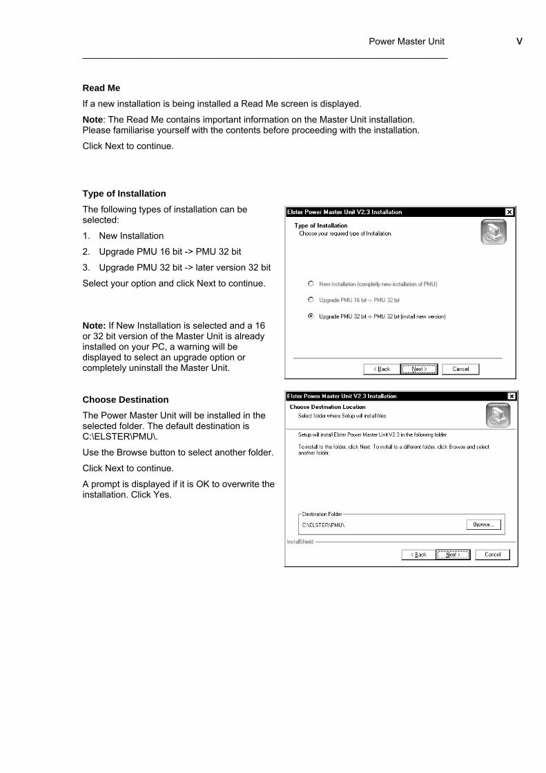
Power Master Unit v _________________________________________________________________
Read Me If a new installation is being installed a Read Me screen is displayed.
Note: The Read Me contains important information on the Master Unit installation. Please familiarise yourself with the contents before proceeding with the installation.
Click Next to continue.
Type of Installation The following types of installation can be selected:
1. New Installation
2. Upgrade PMU 16 bit -> PMU 32 bit
3. Upgrade PMU 32 bit -> later version 32 bit
Select your option and click Next to continue.
Note: If New Installation is selected and a 16 or 32 bit version of the Master Unit is already installed on your PC, a warning will be displayed to select an upgrade option or completely uninstall the Master Unit.
Choose Destination The Power Master Unit will be installed in the selected folder. The default destination is C:\ELSTER\PMU\.
Use the Browse button to select another folder.
Click Next to continue.
A prompt is displayed if it is OK to overwrite the installation. Click Yes.

vi A1120/1140 Programmable Polyphase Meter Users Manual ___________________________________________________________________
Installation Options Click the installation options required. The Master Unit can be installed in the default directories or a directory of your choice by using the Browse buttons.
Click Next to continue.
Note: For an upgrade it is recommended all installation options are selected and Use copy of existing database.
Flag Probe Selection Various probes can be used to communicate with meters via the optical 'FLAG' communications port. These probes are one of two basic types:
Probe with DTR disabled
Probe with DTR enabled
It is important to choose the correct probe for your installation, as optical communications will not be available if the wrong probe is selected.
© Elster Metering Ltd - M181 001 3C - 12/2007

Power Master Unit vii _________________________________________________________________
Select Program Folder This allows the program to be stored on the Start Menu in the folder name of your choice. You may select a folder already on your system or select a new folder. When you have chosen the folder:
Click Next to continue.
Start Copying Files Before the files are copied to your PC, a summary of the files you have selected to install is displayed. Before continuing, check they are the options you require.
Click Next to continue.
Installation Complete The files are copied to your PC.
Click Finish.
Note 1: The Power Master Unit must have a printer attached for correct installation. If a printer is not available a generic print driver may be used.

viii A1120/1140 Programmable Polyphase Meter Users Manual ___________________________________________________________________
© Elster Metering Ltd - M181 001 3C - 12/2007
Scheme Editor Meter Identifiers Passwords Tariff /DisplayDeferred Tariff /DisplayDeferred Tariff Setup Billing Dates Meter Constants Relay Setup Load ProfilingMeter Options User Interface OptionsTime & Date
Readings As Scheme Editor +Current ValuesHistorical RegistersInstantaneous ValuesMeter Physical InfoInstrumentation Values
Scheme Manager Meter Mana gerMeter Information Editor Connection (Comms)TypeElementsRelaysLoad ProfileCommunicationOS & Telephone NumberIdentifiersUtility CodesPasswords
Quick Send
Meter List
Meter Schemes
Execute Meter List
Examine Meter Readings
Register Values, Historical Registers, Load Profile Data, Instrumentation Profile Data, Security Data, Hardware ConfigurationMeter Identifiers, Passwords, Tariff, Deferred Tariff, Billing Dates, Display, Meter Constants, Customer Registers, Relay Setup,Load Profiling, , A1120 Options, A1120 UI Options, Time & Date
Changing Passwords Defining a New UserFile LocationsMeter Connection SetupComms Server SetupBack-up DatabaseTime Set ModeLanguage
Systems Administration
A1120/40 Power Master Unit Overview
Power Master Unit 1 _________________________________________________________________
Power Master Unit
1.1 Power Master Unit Introduction This section gives the basics on how to use the Power Master Unit software.
The Power Master Unit (Referred to in this manual as the Master Unit) software is a menu driven package designed to support all variants of Elster Metering Systems:
A1700 (PPM) Polyphase Commercial and Industrial Meters
A1120/40 Light Industrial and Commercial Meters
A120/140 Electronic Single-phase Domestic Meters
Power Master Unit meter compatibility does not allow different meter types to be programmed by the same scheme, therefore a separate manual support's each application. This manual supports A1120 and A1140 meters only. For information on how to program the A1700 and PPM meters, see manual M120 001 6.
To program A120/140 meters, see manual M130 001 3.
The key features of the Master Unit software are:
Menu driven, using Microsoft ® Windows based operating software to guide the user through the process of setting up a meter for any particular application.
Programming structure to ensure that, if an attempt is made to program a feature that is not present in a meter, erroneous data cannot be programmed.
All other features are programmed normally.
The Software permits:
Reading and Programming directly through the optical port
Reading and Programming through the serial port either directly or via a modem
Reading and Programming indirectly via a Hand Held Unit (HHU) through the optical port
Transferring information to and from a HHU
1.2 Prerequisites This tutorial assumes you are comfortable with the 'Microsoft Windows' environment.
The Master Unit is Windows™ compatible, but if you are uncertain of the Windows structure, it is worth spending a little time familiarising yourself with the 'Brief Tour of Microsoft Windows' in the Windows manual before entering the software.

2 A1120/1140 Programmable Polyphase Meter Users Manual ___________________________________________________________________
1.3 Logging On to the System Open the Power Master Unit from the appropriate directory to display the Master Unit Logon dialog.
For security reasons, only users with a direct knowledge of the correct User id and Passwords will be permitted to Log On to the Master Unit software. The Password is initially set to Elster. This should be changed as soon as possible to prevent unauthorised access to the Master Unit. The password may be changed using the System/Change Password dialog from the Main Menu bar.
To enter the system a User name with the correct Password must be entered. Three attempts to match the Password with the User name are allowed before access is denied. If a match is not found, a message is displayed and the program exits.
Select the User Name and enter the password. The system enters the Master Unit main menu.
The default password is:
User Name Elster
Password Elster
Note: Administrator access is for certifying or building meters only. For details of Administrator access, contact Elster Metering Systems.
1.4 Features of the Main Master Unit Window When the software is first entered, the Main window is displayed. The Window is divided into elements consisting of three Action Windows and a Status Bar.
Action Windows There are three action windows, the Scheme manager, Meter manager and the Meter list.
The Scheme and Meter manager function in a similar way and consist of two panes. The left pane is divided into a series of folders and sub folders. These folders represent Scheme related and meter information. The right pane consists of objects that relate to an opened folder.
The Meter list brings together a meter or number of meters from the Meter manager and a scheme or a number of schemes from the Scheme manager to produce a list of meters and their associated schemes.
© Elster Metering Ltd - M181 001 3B - 5/2007

Power Master Unit 3 _________________________________________________________________
Techniques used on the action windows
Selecting Objects or folders Point at the object or folder and click the left most mouse button.
The object or folder will appear highlighted.
Opening folders In the Scheme Manager, double click the leftmost mouse button on Schemes. The folder will open to show further folders. Dragging and dropping objects or folders Valid objects or folders can be moved from the Meter manager or Scheme manager to the Meter list using drag and drop techniques.
Meter ManagerMeters B9918293
B9618294B9918293Meter ListDrag &
Drop
Use of the rightmost mouse button
Point to an object in the Scheme manager and click the rightmost mouse button. A menu appears.
1.5 The Main Window This section provides an overview of the Master Unit Software. The use of the components of the Window is detailed in the section, Features of the Main Master Unit.

4 A1120/1140 Programmable Polyphase Meter Users Manual ___________________________________________________________________
Menus
File New Scheme: Opens a new blank A1700 (PPM), A1120/40 or A120/40 Scheme in the Scheme manager ready to be edited. Open: Opens an existing file ready to be edited ------------------------------------------------------------------------------------------------- Open Meter List: Opens the Load Meter list Action Window. Select a Meter list and press Load to open the list. Save Meter List: Allows a new Meter list to be saved. Save Meter List As: Allows a Meter list to be edited and saved as a new name. ------------------------------------------------------------------------------------------------- Logoff ELSTER: Logs off the current user Exit: Quits the Master Unit
Edit Cut - Remove a highlighted object and insert it on the clipboard, then use the paste facility to paste it in a folder
Paste - Paste a cut object from the clipboard to the selected Manager.
Rename - Rename a highlighted object.
Delete - Delete a highlighted object. (For the Scheme manager and Meter manager the object is inserted into the Trash can).
Tools
Delete RES Files This option allows unwanted .RES files to be deleted.
Import old Master Unit file - This allows files produced in the original Elster Metering Systems Master Unit to be converted for use in the Power Master Unit. Files are imported to the Old Master Unit folder and arranged as a scheme for use in the Power Master Unit.
© Elster Metering Ltd - M181 001 3B - 5/2007

Power Master Unit 5 _________________________________________________________________
Import RES file - This retrieves meter readings from different locations such as a:\ to be transferred to the Master Unit.
Import Scheme/meter - Import a Scheme or meter parameters from another source such as a floppy disk or Network drive.
Export Scheme/meter - Export a Scheme or meter parameters to another source such as a floppy disk or Network drive.
Options
Operation Confirmation - Confirmation gives the option of warning the user if schemes, meters or folders are being moved or deleted.
Automatically Scan for Readings - When selected, all readings files will be automatically imported in the Scheme manager. The default of the scanning frequency is 10 seconds, but this can be altered using the scan frequency dropdown box. If the Master Unit is networked or a low specification PC is being used, leave this option unchecked for faster Master Unit response. Check as required to update the readings using the Automatically scan for readings facility.
Passwords in Meters - This option allows the passwords of A1120/40 meters to be ignored. Default Passwords - This option allows the default passwords to be entered and used as defaults in the Meter Manager. The passwords must match the passwords programmed to the meter. Note: Only uppercase alphanumeric characters may be used.
Transfer
Execute Meter List - This will execute the Meter list currently selected. Quicksend Scheme - This allows a Scheme currently selected to be programmed to a meter, bypassing the Meter list. Launch Communications Server - Opens the Communications Server ready for a communications session Launch CHIRPS - Opens CHIRPS ready for a communications session. Launch OMS - Opens the Open Metering Systems software ready for a communications session with a Hand Held Unit.

6 A1120/1140 Programmable Polyphase Meter Users Manual ___________________________________________________________________
System
Change Password - Used to change the Current User's password.
User Administration - Used to set a User's permissions or add New Users.
File Location - Used to locate System Files.
Meter Connection Setup - Allows communications facilities to be specified.
Communications Server Setup - Allows all communications ports to be configured
View Communications Log - Views the log of communications session.
Back-up Database - Allows a total back-up of the database to be created.
Time Set Mode - Allows a meter's time to be set automatically to the system time, or to a predetermined time.
Language - Allows a language choice to be selected for the strings resources. The Master Unit is then restarted and the new language strings are implemented.
Window
Show Communications Failures Window - Allows all communications failures to be viewed or saved. Saved files may be kept as a record for support purposes.
Arrange - Opens minimised Windows and re-arranges customised Windows to the Master Unit Set-up.
Scheme Editor Pages Each page in the Scheme editor is similar in construction with all fields and controls being used in the same way.
The Meter Constants page is shown opposite. It consists of a Page Identifier and three Check Panels.
© Elster Metering Ltd - M181 001 3B - 5/2007

Power Master Unit 7 _________________________________________________________________
Page Name Identifier This identifier is unique to the page currently being edited. Other pages of this type can be selected using the arrow by the side of the identifier. This allows editing of an existing scheme or new schemes using the same data to be created.
Check Panels The Transformers ratio check panel is shown below and is selected or deselected using the check box in the top left corner.
If the box is unchecked the contents of the panel cannot be altered. The meter functionality or data will remain unchanged.
If the box is checked, the panel becomes operable and the meter functionality or data can be changed.
Using the Toolbar
Restore Scheme The toolbar allows special tasks to be performed by simply pressing the required toolbar button. By laying the cursor over a button, the button name is displayed.
About Help The Power Master Unit Help gives a step-by-step guide on how to enter a scheme into an A1120 meter or A1140 meter.
All information required to program a meter is contained in the Help.
Using the F1 Key Pressing F1 whilst a topic is selected in the Master Unit software displays the topic Help information.

8 A1120/1140 Programmable Polyphase Meter Users Manual ___________________________________________________________________
© Elster Metering Ltd - M181 001 3B - 5/2007

Power Master Unit 9 ___________________________________________________________________________
The Scheme Manager
2.1 Introducing Schemes The Scheme manager allows schemes to be organised or read.
A Scheme can consist of an individual entry, such as a Tariff/Display sequence. This Scheme may be used to program a number of different meters with the same Tariff and Display sequence. This gives the advantage of changing only one parameter or any combination of programmable features of a group of meters, all other parameters remaining unchanged.
2.2 The Scheme Manager Components The Scheme manager is divided into five components.
Schemes - Used to store and organise Schemes.
Readings - Used to store the readings obtained from a meter after the Data transfer of a Scheme incorporating a Read. The Readings can include all Scheme data, Diagnostic data, Load profile data and Status reports. Data Stream Mode allows fast reading of Register Readings, Historical Data and Load Profile Data.
Old Master Unit – Not applicable to A1120/40 meters.
Import - This option allows any valid Power Master Unit file to be imported. Individual or linked files can be selected. For example, if a Scheme is selected for Import, all pages will also be imported.
Trash Can - All files deleted from the Scheme manager are transferred to the Trash can. They can be transferred back to the Scheme manager using cut and paste or by selecting the file and dragging it to the scheme folder. To empty the Trash can, select the items and press Delete. The entries are removed from the database.
Warning - Once files have been deleted they cannot be recovered.

10 A1120/1140 Programmable Polyphase Meter Users Manual ___________________________________________________________________
© Elster Metering Ltd - M181 001 3C - 12/2007
2.3 Scheme Manager Once a component of the Scheme manager has been selected, a Context Menu with the options shown opposite becomes available. Select A1120/40 scheme. Options obey standard Windows conventions and are viewed by pointing at the right pane of the Scheme manager, then right clicking the mouse.

Power Master Unit 11 ___________________________________________________________________________
Scheme Editor
3.1 Selecting the Meter Type Before using the Scheme editor, the type of meter to be programmed must be selected. Select File/New/A1120/40 Scheme and open the scheme. Select Compatibility on the Main Menu Bar.
Select the appropriate meter variant only. From now on the Power Master Unit will only display parameters applicable to the selected model(s) of A1120/40 Meter. It is strongly recommended that only one meter variant is selected at a time. If more than one variant is selected and a Scheme is created, scheme parameters applicable to the lowest specification of meter only will be available for selection. To Select meter compatibility - Select compatibility A1120 in the Scheme Editor then select meter variant. If 'Save as Default' is checked, the selection will be saved and used as the default when the Power Master Unit is powered up and new schemes are created.
3.2 Scheme Editor As an entry is made to a Scheme, the entry in the Summary changes to Bold (See opposite). This allows quick verification of Scheme entries.
Care should be taken when entering a Scheme to ensure the correct parameters are selected for generic meter models. If a parameter is not available for a particular model of meter, the meters will still be programmed, but no action will take place for the unavailable parameter. For this reason it is recommended that meter compatibility is selected in isolation.

12 A1120/1140 Programmable Polyphase Meter Users Manual ___________________________________________________________________
Toolbar
The Scheme Toolbar is shown opposite. It consists of the following components:
Restore Scheme
If a scheme has been modified but not saved, restore returns the scheme to its original settings.
Save Scheme
Save scheme saves the current scheme settings.
Quick Send
Quick send allows a scheme to be transferred to the meter.
Sets up the properties for the system printer and allows all pages of the current scheme to be printed.
3.3 Starting a New Scheme To enter a scheme from the Main Window, select File/New/A1120/40 scheme, or right click the mouse in the right pane of the Scheme manager and select New/A1120/40 Scheme.
To Enter a Scheme - In the Main Window, select the File/New/A1120/40 Scheme option. A Scheme called New Scheme is entered in the Scheme manager and is highlighted.
Rename the scheme and press Enter.
3.4 Scheme Editor The Scheme Editor can be used to program all variants of the A1120/40 meter.
© Elster Metering Ltd - M181 001 3C - 12/2007
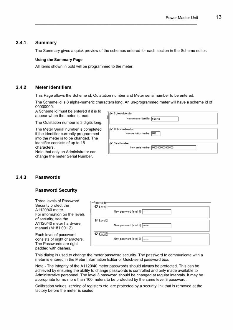
Power Master Unit 13 ___________________________________________________________________________
3.4.1 Summary The Summary gives a quick preview of the schemes entered for each section in the Scheme editor. Using the Summary Page All items shown in bold will be programmed to the meter.
3.4.2 Meter Identifiers This Page allows the Scheme id, Outstation number and Meter serial number to be entered.
The Scheme id is 8 alpha-numeric characters long. An un-programmed meter will have a scheme id of 00000000. A Scheme id must be entered if it is to appear when the meter is read.
The Outstation number is 3 digits long.
The Meter Serial number is completed if the identifier currently programmed into the meter is to be changed. The identifier consists of up to 16 characters. Note that only an Administrator can change the meter Serial Number.
3.4.3 Passwords
Password Security Three levels of Password Security protect the A1120/40 meter. For information on the levels of security, see the A1120/40 meter hardware manual (M181 001 2).
Each level of password consists of eight characters. The Passwords are right padded with dashes.
This dialog is used to change the meter password security. The password to communicate with a meter is entered in the Meter Information Editor or Quick-send password box. Note - The integrity of the A1120/40 meter passwords should always be protected. This can be achieved by ensuring the ability to change passwords is controlled and only made available to Administrative personnel. The level 3 password should be changed at regular intervals. It may be appropriate for no more than 100 meters to be protected by the same level 3 password. Calibration values, zeroing of registers etc. are protected by a security link that is removed at the factory before the meter is sealed.

14 A1120/1140 Programmable Polyphase Meter Users Manual ___________________________________________________________________
3.4.4 Tariff/Display The Tariff/Display Page is divided into six Tabs, Register sources, Define season, Season change over dates, Default, Utility display and Checksum.
Complex tariffs should be entered in a logical manner, by completing each Tab working from left to right.
Note – All tab’s should be completed otherwise some information may be cleared from the meter.
Register Sources 8 Rate Registers, 4 Maximum Demands, 2 Customer Defined Registers
Source Dropdown List
The source of each of the Rate Registers and MD Registers must be defined.
To Select Rate Sources - Double click source for the required rate to reveal the dropdown list then select the required source from the list by hitting return.
Customer Defined Registers
Two Customer Defined (CD) Registers can be used throughout for tariff scheme, cumulative, load profile data and display. They are programmable to accept values from any two of the following like-unit registers: a) kWh total import b) kWh total export
c) Q1 kvarh Import Lagging Energy d) Q2 kvarh Import Leading Energy e) Q3 kvarh Export Lagging Energy f) Q4 kvarh Export Leading Energy
g) Add import kVAh h) Add export kVAh
© Elster Metering Ltd - M181 001 3C - 12/2007

Power Master Unit 15 ___________________________________________________________________________
Examples of their use are: CD Register 1 kWh import + kWh export (a + b) = Total kWh CD Register 2 kvarh import lagging + kvarh import leading (c + d) = Total Import kvarh
Define Seasons
12 Seasons This Tab allows the Seasons to be created. The Seasons are then applied to the Season change over dates.
Each Season must be given a unique name.
This Tab also allows the Rate Source Clock to be displayed in steps of 5, 10, 15 or 30 minutes.
To Defining a Season - Select required Season and name the Season
Click on New Day, name the Day, then press the Add button Double click on Monday to reveal the dropdown list, then select New Day
Click on the Add Rate button. The Rate Source clock is displayed
Place the cursor on the leading edge of the active time (a double arrow will be displayed), then drag to the start time for the Rate. Repeat for the end time of the rate. Alternatively time may be entered directly on the right hand side.
Click on the Add Rate button and repeat for all required Rates and MD’s for this Season
Repeat for all required Days and Seasons
Select Scheme/Save page as from the main menu and save the page
Note 1 - Use copy of existing day type allows a similar day type to be created and saved as a new name.
To create a similar day type, press the New Day button and Check the Use copy of existing day type box. Select the Day type from ‘Existing day types’ then Type the New day name, then press the ‘Add’ button.

16 A1120/1140 Programmable Polyphase Meter Users Manual ___________________________________________________________________
Season Changeover Dates 24 Season Changeover Dates Season Changeover Dates are the dates on which a new season begins. Season Change Over Dates are defined by day, month and season number.
Entering the seasons changeover dates To enter a fixed date - Select the first season then click on the Season Dates column at the start of the required Season. Click and drag to the Season end date
Repeat for all Seasons
Select Scheme/Save page
If a date other than the first day of the month is required for the season start date, click on the ‘day’ tab and use the scroll bar to find the start of the season. Click and drag to the Season end date
To enter a variable date - Check Enable Advanced Season Editing then select the Season. From the Season Change Editor, select Last Monday in April.
Selecting Next starts on Last Sunday in September.
Select OK.
Note: February 29 will only be activated on leap years even if selected, otherwise the February 28 will be used.
The calendar can be viewed by day or by month by selecting the appropriate option at the bottom of the calendar.
Billing Reset A Billing Reset can be activated by selecting ‘perform a billing reset on change season’.
Exclusion Dates 32 Exclusion Dates Exclusion Dates are the dates when the normal switching times for that season are not to be adopted i.e. Public Holidays. Instead, Switching times with defined actions take over.
A switching time for the 1 Jan is shown opposite. The shaded box indicates the season or day to switch to i.e. Holiday is the day type selected to use.
© Elster Metering Ltd - M181 001 3C - 12/2007

Power Master Unit 17 ___________________________________________________________________________
Choosing the Exclusion Date Type The Exclusion Date can be set to one of the following options:
Set to day type – this sets an Exclusion Date to a particular day as defined in the Define season day list
Set to specific day of the same season – this sets the Exclusion date to a specific day of the Season currently selected
Set to specific season – this sets the Exclusion date to the day currently selected of a specific Season. Exclusion Date Repetition The A1120/40 meter Exclusion Date repetition can be applied in the following ways:
Every year
Specified year only
Repeated every four years from the specified date
The set to first option allows the Exclusion date to be applied on a selected day of the week on or after the specified date.
e.g. set 1st Monday after April 25th to obtain 1st Monday in May.
Default Display
Up to 40 Displays can be shown in the A1120/40 Default display sequence.
For ease of building, the displays are arranged in a number of sections which can be chosen from the Selection drop down box. Displays can be in English or displayed as OBIS codes.
To display OBIS codes, check the Enable OBIS codes checkbox.
To change or enter OBIS codes, select the Defaults Tab. Highlight the field to be changed and type in the new code (A maximum of five characters are allowed for the full OBIS code).
Building the display The available displays can be entered using Drag and Drop or by using the Button.
Drag and Drop Click on the required display from the Available displays list and hold down the leftmost mouse button. Drag the selected display Item from the Available display list to the Display list.

18 A1120/1140 Programmable Polyphase Meter Users Manual ___________________________________________________________________
To transfer a group of sequential displays - Click on the first display in the list. Hold down the shift key.
Click the last display required in the list (the displays will appear highlighted) then drag the highlighted displays to the display list.
Using the Buttons To Transfer a display - Select the required display from the Available display list.
Click the button. The display is transferred from the Available display list to the Display list.
To Remove a display from the display list - Click on the required display Click the button. The display is removed.
To Change the display order - Click on the required display and click the button to move the display upwards in the display order.
Click on the required display and click the button to move the display downwards in the display order.
Utility Display Up to 40 Displays can be shown in the A1120/40 Utility display sequence.
The displays are entered in exactly the same way as the Consumer Display.
Checksum This includes a checksum of the complete Tariff/Display Scheme. The checksum can be used to verify the meter is running the same scheme as in the PMU.
3.4.5 Deferred Tariff/Display The deferred Tariff/Display is a pre-defined tariff that will become active specified by the user in the Deferred Tariff Setup.
The setup for the deferred Tariff/Display is exactly the same as Tariff/Display.
© Elster Metering Ltd - M181 001 3C - 12/2007

Power Master Unit 19 ___________________________________________________________________________
3.4.6 Deferred Setup This Page allows the Deferred Tariff/Display to be disabled, or enabled on a specified date.
A Billing Reset on switching to Deferred Tariff can also be actioned.
3.4.7 Billing Dates 13 Billing Dates
This Page allows the End of billing dates to be set. The dates can be set to a date specified by the user or to the last day of each month. Sort Table: Press Sort table to arrange the dates in sequential order.
End of month: Press End of month to enter the last day for all months.
Note: Although the 29th February may be entered, the End of billing will occur on the 28th of February for non-leap years.
Perform billing reset during communications option - When selected, this option causes a billing reset to be performed at the end of each communications session.
Enable Auto-reset - When selected the meter will perform a Billing Reset and store all Historical data every midnight. At each Billing Reset the oldest of the fifteen historical data records will be overwritten. Automatic end of billing dates take precedence over the enable auto reset.
Reset Maximum demands - When Enable Auto Reset is enabled, checking the Reset Maximum Demands checkbox will reset the maximum demand registers.
The highest demand of each maximum demand register is added to the corresponding cumulative maximum demand register.

20 A1120/1140 Programmable Polyphase Meter Users Manual ___________________________________________________________________
3.4.8 Meter Constants Transformer Ratios The A1120/40 Meter can be supplied for the following types of connection:
Direct connected or CT operated.
The screen shows connection for a CT operated meter.
The maximum CT Ratio is 500:1
Performing a Billing Reset on CT Ratio Change
Check the panel to perform a billing reset when the meter CT Ratio is changed. CT Ratio Display
The meter can display the CT as a ratio or as a scalar quantity. Check the panel to display as a CT Ratio. Leave unchecked to display as scalar. CT Error
The CT error can be compensated for.
To compensate for a CT error of +0.4%, enter a value of +0.4%, then a compensation value of -0.4% will be applied.
Note: If the CT programming switch is fitted to the meter, the switch must be activated in order to change the CT ratio.
3.4.9 Relay Setup The pulsing output of the A1120/40 meter can be configured to one of the following options:
Retransmit Rate indication
Retransmit Retransmit is selected along with the appropriate Source, Pulse value and the Pulse width.
Ensure that the chosen pulse value and pulse width leaves adequate gaps between pulses at maximum meter loads.
© Elster Metering Ltd - M181 001 3C - 12/2007

Power Master Unit 21 ___________________________________________________________________________
Rate Registers
This option is used to close the relay if any of the rate registers or combinations of the rate registers are active. Using the buttons Use the ≤ button to select the Rate(s)
Remove a rate register, use the ≥
To St all rate registers, use the ‹‹Remove all rate registers, Use the ››
3.4.10 Load Profiling The A1140 meter records block demand only. The Integration period may be set to 1, 2, 3, 4, 5, 6, 10, 15, 20, 30 or 60 minutes.
Up to four channels can be selected to be included in the load profile definition.
3.4.11 Meter Options
Clock Clock source - The time keeping of the meter can be derived from the AC supply or from the internal crystal oscillator. If AC supply is selected, the crystal will take over in the event of a supply failure.
Load profiling – The A1140 can be set to observe daylight savings (See 3.4.13, Time and date) or to ignore daylight savings.

22 A1120/1140 Programmable Polyphase Meter Users Manual ___________________________________________________________________
Register Formats (LM ********-A) Register formats allow the decimal point style and the number of digits, number of decimal places and the display scale to be selected for cumulative and demand registers.
LM ********-C
Custom Cumulative Register Formats can be set for Main, Ext Set 1, Ext Set 2 and Ext Set 3.
Date Formats This defines the way the Date is displayed on the LCD. The selection is made from the dropdown lists. The following formats are available – dd mm yy mm dd yy
Communications The communications TAB gives the following option:
Enable or Disable Serial port Allows the serial port to be enabled or disabled.
Serial Port Baud Rate Allows the serial port baud rate to be set to one of the following: 300, 600, 1200, 2400, 4800, 9600.
Serial Port Configuration Allows the port data bit configuration to be set to an option from the dropdown list. The following options are available:
7 bits, even parity, 1 stop bit
8 bits, no parity, 1 stop bit
Data Stream Mode meters should be set to 8, None, 1.
Communication Turn-around Time
This is a programmable time before which the meter will respond for a request for data. The default is 200ms.
© Elster Metering Ltd - M181 001 3C - 12/2007

Power Master Unit 23 ___________________________________________________________________________
Modem Power Supply Disable Serial Port Power - The power for the modem is disabled
Always Power Serial Port - The power to the modem is permanently enabled
Interrupt Serial Port Power - To ensure the correct operation of any device connected to the serial port, power to the port is interrupted for 20 seconds at a programmable period (1 - 24 hours) set by the user.
If a communications session is active the reset will occur at the end of the communications session.
Note: If a modem is installed which draws too much power from the meter, a transient reset occurs and the modem power supply is disabled to prevent continuous resetting of the meter. The power supply can be re-enabled via the IEC 1107 port by using the ‘Always power serial port’ or ‘Interrupt serial port power’ facility.
Error Handling The Error handling tab is shown opposite. Battery or Clock Fail Action - If the battery in the meter has failed and a supply failure also occurs, when power is restored the time and date of the battery failure will be logged.
In this event the meter can do one of three things:
Continue on the tariff scheme, with a consequent time error equal to the duration of the supply failure.
Action End of Billing Reset, then continue using the tariff as normal.
Action End of Billing Reset and freeze the tariff.
Reverse Run Configuration - This allows reverse run events to be recorded for an import only meter, or to be omitted for an import/export meter. Active Phases for Phase Failure Monitoring - For normal operating conditions, all three phases are enabled. For certain configurations (e.g. 2 phases of a 3 phase 4 wire) only the red and blue phases are activated. Leaving the yellow phase unchecked allows display messages and load profile flags to be inhibited for the yellow phase. Install External Battery - This allows the Read Without Power battery to be installed.
Voltage Phase Failure Threshold - The voltage phase failure threshold is applied to the voltage connected directly to the meter terminals.
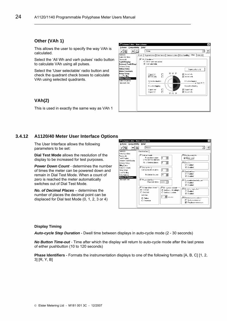
24 A1120/1140 Programmable Polyphase Meter Users Manual ___________________________________________________________________
Other (VAh 1) This allows the user to specify the way VAh is calculated.
Select the ‘All Wh and varh pulses’ radio button to calculate VAh using all pulses.
Select the ‘User selectable’ radio button and check the quadrant check boxes to calculate VAh using selected quadrants.
VAh(2) This is used in exactly the same way as VAh 1
3.4.12 A1120/40 Meter User Interface Options The User Interface allows the following parameters to be set:
Dial Test Mode allows the resolution of the display to be increased for test purposes.
Power Down Count - determines the number of times the meter can be powered down and remain in Dial Test Mode. When a count of zero is reached the meter automatically switches out of Dial Test Mode.
No. of Decimal Places – determines the number of places the decimal point can be displaced for Dial test Mode (0, 1, 2, 3 or 4)
Display Timing
Auto-cycle Step Duration - Dwell time between displays in auto-cycle mode (2 - 30 seconds)
No Button Time-out - Time after which the display will return to auto-cycle mode after the last press of either pushbutton (10 to 120 seconds) Phase Identifiers - Formats the instrumentation displays to one of the following formats [A, B, C] [1, 2, 3] [R, Y, B]
© Elster Metering Ltd - M181 001 3C - 12/2007

Power Master Unit 25 ___________________________________________________________________________
Voltage Phase Status - Allows the voltage phase indicators (L1, L2, L3) to be displayed as phase fail or phase present. The indicators can be enabled or disabled from the display.
Billing Reset Lockout - Manual billing resets can be locked out until midnight or locked out for a set duration. Display Overrides - Allows the meter error message to be omitted from the display. Error (Alarm) Icon - This option allows the Error Icon to be omitted from the display.
Quadrant Icon - This option allows the quadrant icon to be omitted from the display.
Communications Indicator - This option allows the communications indicator (o optical, r remote) to be omitted from the display. End of Billing Button - This option allows the End of Billing button to be enabled or disabled.
Reverse Run Indicators - This option allows the System Reverse Run Indicator to be enabled or disabled and the per phase reverse run indicators (flashing L1, L2, L3) to be enabled or disabled.
3.4.13 Time & Date
Meter Time Adjustment This allows the meter time to be adjusted in the following ways.
1. Set the Meter time to the PC (or HHU) clock time
Password level 1 allows Time Adjust
Password level 3 allows Time Set
2. Time adjust the Meter time (by 5 seconds every integration period), until the Meter time matches the PC Clock time. The maximum time a meter can be adjusted is +/-7.5 minutes.
Daylight Savings Daylight Savings can be advanced or retarded by 1 or 2 hours or can be disabled.
Enter the Week (1 to 4, Last), Weekday, Month and Hour for Advance and Retard for Daylight Savings. Week/Last will action Daylight Savings on the last Weekday of the month.
Note. The advance and retard need to be the same.

26 A1120/1140 Programmable Polyphase Meter Users Manual ___________________________________________________________________
© Elster Metering Ltd - M181 001 3C - 12/2007

Power Master Unit 27 ___________________________________________________________________________
Reading & Examining Meter Data
4.1 Open Data to Read Editor To open the Read Editor, refer to Section 2.1.
This Editor allows the Register Values, Instantaneous Values, Load Profile Data, Scheme Page Information and Other information to be read back from a meter.
Note: If 1 Day's Load Profile Data is selected, the data read back is the current day’s data from midnight to the end of the last demand period.
Current Values
Instantaneous values

28 A1120/1140 Programmable Polyphase Meter Users Manual ___________________________________________________________________
4.1.1 Data Stream Mode Data Stream Mode allows data to be read back from the meter via the serial port and optical communications port much faster than the normal Data to Read mode. Data Stream Mode is available to read all data.
To use the Data Stream option via the serial port, the Serial Port configuration in the A1120/40 options/communications page must be set to 8 (eight bits), none (no parity), 1 (one stop bit)
4.2 Readings Viewer The Readings Viewer allows data read back from a meter to be examined.
To View the Readings
Double click on the new data to read in the scheme manager
Double click one of the readings to view the data read back from the meter.
Generally these are displayed in a similar format to which the data is entered.
© Elster Metering Ltd - M181 001 3C - 12/2007

Power Master Unit 29 ___________________________________________________________________________
4.2.1 Viewing Load Profile Data Load profile data read back from a meter can be viewed using the readings Viewer.
Click on Load Profile Data from the readings to view the screen below.
Graph Load Profile readings can be displayed as a graph.
The actual value of data can be viewed by placing the cursor on the plotted readings.
Data shown in red shows data with a 'Flag' set.
To determine the type of flag set, simply lay the cursor over the red area of data. The type of Flag in Readings and Flag box can be viewed in the bottom right hand corner of the screen.
View the type of Flag in the Readings and Flags box in the bottom right hand corner of the screen.
Report A Report of the number of days Load Profile data for a given channel can be displayed and printed from a given date.
The Hardware configuration of the meter can also be displayed.

30 A1120/1140 Programmable Polyphase Meter Users Manual ___________________________________________________________________
Functions This dialogue allows a CSV (Comma, separated variable) file to be exported ready for viewing in a spreadsheet such as Excel. Alternatively the data can be exported in a file format that is suitable for being transferred into an MV90 system.
© Elster Metering Ltd - M181 001 3C - 12/2007

Power Master Unit 31 ___________________________________________________________________________
Meter Manager
5.1 Meter Manager Introduction
The Meter manager is used to organise the systems meter's. It is used to invoke the Meter Information editor.
The Meter manager consists of three components.
Meters - This is a list of meters available on the system. It allows Meter Connection information, Identifiers and Security information to be configured.
To Enter a New Meter Right click in the right hand pane of the Meter manager, select New Meter and rename the meter.
Import - Schemes/meter that have been set up in other Master Units can be imported and placed in the Schemes/meter Import folder.
Trash Can - All files deleted from the Meter manager are transferred to the Trash Can. They can be transferred back to the Meter manager if required. Once deleted from the Trash Can the files are no longer available to the system.
Meter Manager Context Menu
Most of the features of the Context Menu are the same as the Scheme manager. The menu is made available by right clicking the mouse in the right pane of the Meter manager.
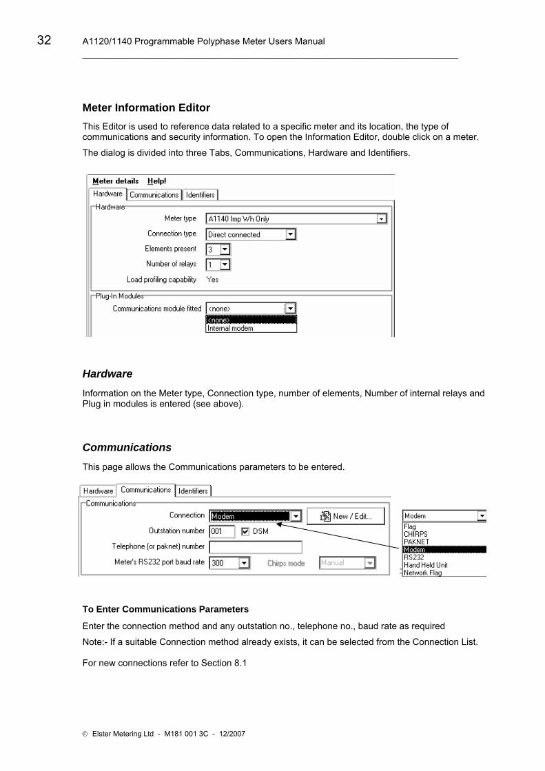
32 A1120/1140 Programmable Polyphase Meter Users Manual ___________________________________________________________________
Meter Information Editor This Editor is used to reference data related to a specific meter and its location, the type of communications and security information. To open the Information Editor, double click on a meter.
The dialog is divided into three Tabs, Communications, Hardware and Identifiers.
Hardware
Information on the Meter type, Connection type, number of elements, Number of internal relays and Plug in modules is entered (see above).
Communications This page allows the Communications parameters to be entered.
To Enter Communications Parameters
Enter the connection method and any outstation no., telephone no., baud rate as required
Note:- If a suitable Connection method already exists, it can be selected from the Connection List. For new connections refer to Section 8.1
© Elster Metering Ltd - M181 001 3C - 12/2007

Power Master Unit 33 ___________________________________________________________________________
Note 2:- The PC’s baud rate should be set as follows – For RS232 connection the PC baud rate must match the A1120/40 baud rate – For Modem connection the baud rate should be set to the specification of modem connected to the A1120/40 meter.
Identifiers
Identifiers allow the Meter Serial Number, the Site id and a description of the meter to be entered.

34 A1120/1140 Programmable Polyphase Meter Users Manual ___________________________________________________________________
© Elster Metering Ltd - M181 001 3C - 12/2007

Power Master Unit 35 ___________________________________________________________________________
Meter List
6.1 The Meter List Components The Meter list consists of a list of meters with their associated Schemes brings together meters configured in the Meter manager, and Schemes created in the Scheme manager, to create a list of meters and their associated schemes.
This is achieved by copying a Meter and a Scheme into the Meter list.
Note 1: If a Scheme is incompatible with a meter, warning triangles appear as shown opposite. Right click on the meter or scheme and select Show Conflicts to establish the reason.
Note 2: Multiple schemes can be sent to a meter as a single communications session by attaching the schemes to the meter using drag and drop. It should be noted that if the same scheme page (e.g. display page) is contained in more than one of the schemes, only the page from the last scheme attached is programmed to the meter.
Meter List Context Menu The options available from the dropdown list are shown opposite. The Context Menu list is made available by right clicking the mouse in the right pane of the Meter list.
New Meter List The New option clears the Meter list ready for a new Meter list to be created.
Open Scheme - This allows information on the meter or meter scheme to be viewed or edited using Save. A new Meter List can also be created by editing the Meter List and Using the Save As facility.
Remove - Removes the selected list from the Meter List
Show Conflicts - Shows any discrepancies between the scheme and the meter
New Meter List - Allows a new Meter list to be created
Open Meter List - Allows a selected Meter list to be opened
Save Meter List - Allows the current Meter list to be Saved
Save Meter List As - Allows the selected Meter list to be saved as a new name
Execute Meter List - Execute Meter List is used for communicating with a meter. It is used with the Meter Communications Server to Program or Read.

36 A1120/1140 Programmable Polyphase Meter Users Manual ___________________________________________________________________
© Elster Metering Ltd - M181 001 3C - 12/2007

Power Master Unit ______________________________________________________________________________
37
System Administration
7.1 System The System menu allows Users to change their password and create new users. It also allows other parameters shown opposite to be entered.
Changing Passwords This allows the password for a User to be changed.

A1120/1140 Programmable Polyphase Meter Users Manual _____________________________________________________________________________________
38
Defining a New User To protect the Schemes and Data, Users can define `lower levels' of Users who do not require full access to the system resources. Click on System then select User administration. This opens the Security Dialog.
Note: Properties can be moved from one window to another using drag and drop.
To Create a New User Select User Administration, User, Create New User
Type the new user name
Go to User Change Password, enter the new password and press OK
Click on a permission and drag it to the required window (Read Only or No Access)
Select other required permissions and repeat
Select User, Save
Don't forget your Password Note: Users can grant access to new users they create only if they have access to the permissions themselves.
If a number of permissions require dragging to another window, hold down the shift key, drag the cursor over the required permissions to select a block of permissions then click on the highlighted permissions and drag them to the required window.
Permissions - Permissions are used to transfer topics from one window to another in the same way as drag and drop.
Select a topic in No Access, select Permissions/Move to Edit. The topic then moves to the Edit panel.
Use the Restore option from the Users dropdown list to return to the original Administrator selection.
Use the Delete option from the Users menu list to delete the selected User.
© Elster Metering Ltd - M181 001 3C - 12/2007

Power Master Unit ______________________________________________________________________________
39
File Locations File location points the Master Unit to the location of externally produced files that may require importing into the Master Unit. File types are shown in the left column and the setting (location) in the right column.
To Modify a File Location, click on Modify and select the directory where the files of the selected type are located then Press OK.
Meter Connection Setup This dialog is used in exactly the same way as the Connections Setup in the Meter information editor.
Communications Server Setup The Communications Server Setup is used to assign the type of communication to be used on each port and organise the Server File paths.
To enter the server setup, Select System/Communications Server Setup from the Scheme manager Main menu.

A1120/1140 Programmable Polyphase Meter Users Manual _____________________________________________________________________________________
40
To select the comms port - Select the comms port (1 - 16) then double click on the type of communications from the dropdown list.
Auto Detect - This automatically detects the hardware available on a selected port and assigns it to the port.
Disable DTR Various probes can be used to communicate with meters via the optical 'FLAG' communications port. These probes are one of two basic types:
Probe with DTR disabled
Probe with DTR enabled
It is important to choose the correct probe for your installation, as optical communications will not be available if the wrong probe is selected.
Modem Init - If a modem is selected on a port, Modem Initialisation allows the initialisation string to be set. The modem type (tone or pulsed dialling) must first be selected.
To set the string, select Modem, select the type of dialling then type the string in the box provided and press Save File Location - To modify a file path, press Modify and edit the file path accordingly.
Use number of retries to set the number of times the computer tries to connect.
Result (.RES) File Management - This option allows the user to Append new data to a .RES file or Always overwrite the .RES file with new data.
If Append new data is selected, any new data is added to the .RES file. This option is used if the .RES files are to be used outside the Power Master Unit.
Note – If this option is used, old readings are stored in the database and new readings are appended.
Always overwrite with new data is the option normally used. This overwrites any old data with the new data.
© Elster Metering Ltd - M181 001 3C - 12/2007

Power Master Unit ______________________________________________________________________________
41
Communications Server Log The communications server log keeps a record of all communications sessions with meters. The log records the following parameters:-
Time and Date, Meter Serial Number, Scheme Identifier, Transmit/Receive data, Status.
Back-up Database Back-up database allows all files in the database to be backed up. It is recommended that the database is backed up at least once a week and that the files are stored on a separate computer. The file format is shown opposite.
Time Set Mode Time set mode can be set from the Real Time Clock (RTC) or Hand Held Unit (HHU) or from a time specified by the User. This mode is used to override the Set to PC option in Scheme manager Time and Date. It does not affect the System time.
Note:- This option will only take effect if the Scheme has Set to PC/HHU Clock configured as part of the Scheme.

A1120/1140 Programmable Polyphase Meter Users Manual _____________________________________________________________________________________
42
© Elster Metering Ltd - M181 001 3C - 12/2007

Power Master Unit ______________________________________________________________________________
43
Communications
8.1 Communications Methods Communications are set up within the Meter manager using the Meter information editor.
The set up requires the communications type etc., an outstation number and telephone number depending on the communications type to be defined.
Connections
To Set- up/Modify a Connections for a modem
Create a New Meter from the Meter manager. Type in the new name (Test)
Double click on the meter and Select Communications
Press New/Edit to display the dialog above
Click New Connection and enter the connection name
Select the method of connection (Modem)
Select the modem serial port (Com 1)
Press Save, then Close
Once the Connection is complete, type in the Outstation number, Telephone number and Baud rate to complete the communications setup.

A1120/1140 Programmable Polyphase Meter Users Manual _____________________________________________________________________________________
44
Methods of Connection
Modem - Modems are connected to a meter via the RS232 communications port and the Elster Metering Systems Communications Server. The Communications Serial Port, Outstation number and Telephone number also require entering.
PAKNET - PAKNET connects a meter via a PAKNET Radio PAD and the RS232 communications port and the communications server. The Communications Serial Port, Outstation number and PAKNET PAD number also require entering.
Flag - Flag connection allows communication with a meter via the meter's Optical Port.
RS232 - RS232 connection allows an A1120/40 to be targeted for communications. The baud rate is selectable. Data Steam Mode allows fast data readings.
CHIRPS - This option allows CHIRPS files to be created.
To create a CHIRPS file, select CHIRPS, select the Directory where the Chirps files are stored and press OK Hand Held Unit - This allows the Master Unit to communicate with a Hand Held Unit via OMS software.
Proxy Flag - Manufacturing facility only
Network Flag – For connection to Ethernet, select Hardware and select the meter type, select Communications and Connection/Network flag then Press New/Edit and enter the Host and Port address.
The Host port address of the Ethernet module connected to the meter would be typically 192.168.0.2:14001 (Contact your local IT Department).
© Elster Metering Ltd - M181 001 3C - 12/2007

Power Master Unit ______________________________________________________________________________
45
8.2 Sending a Scheme to Meter There are two ways of sending a Scheme to a meter, by executing the Meter list or by Quick send scheme.
Execute Meter List Execute Meter list can be selected from Transfer in the Main menu, or by right clicking in the Meter list.
To Transfer a Meter List Select the Meter list to be transferred then select Transfer/Execute Meter list. File transfers should be visible in the Communications Server
Quick Send Scheme This allows the user to send a complete scheme to a meter, by-passing the Meter list. Quick send can be selected using the toolbar or by saving the scheme, then right clicking on the scheme icon.
To Quick send a Scheme Select the Scheme to be transferred
Select Quick send Scheme from Transfer in the Main Menu. This will open the Quick send Setup dialog
Fill in the dialog referring to Connections
Press OK. File transfers should be visible in the Communications Server
8.3 Communications Server
Introduction Communications with a meter is automatically established via the Communications Server, when a Scheme is executed from a Meter list or in Quick send mode. The server is used for the following modes of operation that are set in Meter Information Editor/Communications:
Modem, Paknet, Flag or RS232

A1120/1140 Programmable Polyphase Meter Users Manual _____________________________________________________________________________________
46
When a Meter list is executed, the Communications Server opens on the desktop, showing data being transferred in Red (Transmit) or Green (Receive) blocks of data in the Communications window. Communications can take place on up to nine Ports.
To view data in the form of a Log while it is being transferred, click in the Communications Window. The data being transferred is displayed as a log while communications take place.
Data Log
Notes 1. During Comms the Serial number and Scheme name are displayed once connection to the meter is
established. If this data is not available, ? is displayed
2. The number of sent and received Packets is displayed with the number of bytes
3. The program can be aborted during comms by clicking Exit. This will end all sessions in an orderly manner.
4. It is recommended that the comms application is closed down once the Master Unit has been closed
8.4 Main Menu
File Open - Allows files stored on the PC to be Read and Viewed
Close - Closes an opened file
Save - Saves an opened file
Save/As - Saves a file as a New Name
Print Preview - Shows page layout of a file to be printed
Print - Prints an opened file
Print Setup - Configures the System Printer
Exit - Exits the Communications Server
Window Arrange - Arranges customised Meter manager, Meter list and Scheme manager windows to original view.
© Elster Metering Ltd - M181 001 3C - 12/2007

Power Master Unit ______________________________________________________________________________
47
8.5 Viewing Communications Failures To view the log of communications
failures select Window, Show communications failures.
A log of all failures encountered during the current Master Unit session will be displayed.
Use Save to save the error messages as Text Files. The file will contain information required to analyse the failure. Use the text files if support is required when contacting Elster Metering Systems about communications failures.
8.6 Networking the Power Master Unit Client PC runningPower Master Unit Software Server PC with
Communications Server installed
The Power Master Unit can communicate over a network by installing the Communications Server on a remote PC and sharing the directory. The file location must be set in the Communications Server Setup.
Setting the File Paths At the Server PC: Install the Communications Server in the required directory and share the directory including the Script, Result and Log subdirectories with the Client PC
Select the Communications Server Setup and change the Script, Log and Results path to the correct location on the Server PC
At the Client PC: Connect to the share on the remote PC running the Communications Server
Select the Communications Server Setup from the System Menu and set the Script, Log and Results path to the correct location on the Server PC
Note:
To allow communications from a number of Power Master Units connected to a network, the Communications Server must be left running when it is installed on a remote drive.

A1120/1140 Programmable Polyphase Meter Users Manual _____________________________________________________________________________________
48
© Elster Metering Ltd - M181 001 3C - 12/2007

Power Master Unit ______________________________________________________________________________
49
Appendix A
A1 Exporting Readings as a Text Only File Readings and Schemes can be exported and printed as a text only file by setting up a “generic/text only” printer on port “file”. This feature allows schemes/readings (or selected parts of) to be cut and pasted into other applications such as Bug Collector Pro, Word etc.
Setting up the File printer From the Main Window, choose Start/Settings/Printers
Select Add/New/Printer. The Add Printer Wizard appears
Press Next. Select File
Press Next. Select Manufacturer/Generic, Printer Generic/ Text only
Press Next. Select keep existing drivers
Press Next. Select No for default printer
Press Finish
A Print to File dialog appears
Name the file (text Printer)
All files output to this printer will be printed as text only files and can be viewed in Notepad.

A1120/1140 Programmable Polyphase Meter Users Manual _____________________________________________________________________________________
© Elster Metering Ltd - M181 001 3C - 12/2007
50
A2 Live Link The live link software displays instrumentation details as shown in the display opposite.
Using the software Select a meter from the Meter Manager
Right click and select Live Link
Data will be read back from the meter
Note: The Include log data in network output box in System/Communications Server Setup/Client setup must be checked for data to be viewed.

Power Master Unit ______________________________________________________________________________
51
Appendix B
B1 OMS Software OMS software forms part of CHIRPS and is configured in the CHIRPS directory.
OMS will allow a variety of Hand Held Units (HHU) to be used with the system.
The software can be used to transfer schemes to a HHU from the Power Master Unit, using either Quick send or executing a Meter list.
The software can also be used to upload .RES or .BUD files from a HHU by launching the OMS Transfer program.
B2 Downloading Schemes Select Quick-send
Select the connection type (HHU) and enter the password as required
Click OK
The Window shown is displayed
Click OK The OMS top level menu is displayed

A1120/1140 Programmable Polyphase Meter Users Manual _____________________________________________________________________________________
52
Hand Held Unit (HHU) HHU allows data files and configuration data to be downloaded using a HHU.
System HHU
Set UpTransferSave Set UpConfig File
Click on HHU to reveal the following menu.
Set Up
Mpalm 3000
XX
Click on Set Up
The meter, Master Unit path and procedures are set up automatically by the Power Master Unit and should not be changed. The HHU and the Comm port should be set up as appropriate. Click OK when all parameters are set. Note: If any modifications are made they can be saved by selecting HHU/Save Set Up. Download - To download the files to HHU, follow the flowchart below:
With CHIRPS for the HUSKYSelect Comms
This starts HCOMor
At C> Type HCOMPress Enter
HUSKY File transfer Utility‘Press Escape to Exit’ is displayed
At the PCAt the HHU
Select HHUClick Transfer
Files are transferred to the HHU
After Transfer Press ESC
Select SystemExit
© Elster Metering Ltd - M181 001 3C - 12/2007

Power Master Unit ______________________________________________________________________________
53
Programming/Reading a Meter
A
t the HHU
At the C> prompt typeCHK (HUSKY)
Press Enter
Select ManualPress Enter
Select scheme to be transferredPress Enter
When the transfer is completethe HHU responds with an
Achievement Byte(0 if successful)
Select QuitPress Enter
Uploading Readings - In the Power Master Unit, select Transfer/Launch OMS HHU Transfer Program from the Main Menu.
Mpalm 3000
\OMS_TRAN\RESULTS
X
Click OK (OMS top level menu is displayed)
Click on HHU/Set up
Power Master Unit sets up the Meter, Master Unit path and Procedures automatically. If the load profile data has been read, check Upload BUD Files. The HHU and the Comm port should be set up as appropriate. Click OK when all parameters are set. Note: If any modifications are made, selecting HHU/Save Set Up can save them. Upload - To Upload the files from HHU, follow the flowchart below:
With CHIRPS for the HUSKYSelect Comms
This starts HCOMor
At C> Type HCO MPress Enter
HUSKY F ile transfer Utility‘Press Escape to Exit’ is displayed
At the PCAt the HHU
Select HHUClick Transfer
Files are transferred to the PC
After Transfer Press ESC
Select SystemExit

A1120/1140 Programmable Polyphase Meter Users Manual _____________________________________________________________________________________
54
Configuration
If the HHU.CFG on the HHU is lost or corrupt, a new configuration file can be downloaded to the HHU.
Select HHU/Config File.
Set the parameters as shown below:
HHU Config. File
Number of Retries 5 Date of Expire 311279 Number of Sessions 0000 HHU Identification HuskyFS2 File Size 12 Comms Port COM1 Timing 1 1600 Timing 2 3000 Timing 3 0200 Timing 4 0100 OK Cancel
Click on data to be edited and type changes. (TAB can also be used to move between entries). Click on OK
Select HHU/Set up
In the procedures section, only Download HHU Config should be selected
Click OK
With CHIRPS for the HUSKYSelect Comms
This starts HCOMor
At C> Type HCOMPress Enter
HUSKY File transfer Utility‘Press Escape to Exit’ is displayed
At the PCAt the HHU
Select HHUClick Transfer
Files are transferred to the HHU
After Transfer Press ESC
Select SystemExit
Number of retries - This is the number of tries CHIRPS repeats the FLAG message before terminating with an error message.
© Elster Metering Ltd - M181 001 3C - 12/2007

Power Master Unit ______________________________________________________________________________
55
Date of Expiry - This is the date of expiry of the current CHIRPS Configuration File. A new file with the following format must be loaded. Day of Month ( 2 Characters) 01-31 Month ( 2 Characters) 01-12 Last 2 digits of Year ( 2 Characters) 00-99
Number of Sessions - This is the number of sessions that CHIRPS will run in the range of 0000 to 9999. After entry the value decrements by one until it reaches 0001. CHIRPS will then cease to run.
If the number is initially set to zero, CHIRPS will run for an indefinite number of times.
HHU Identification - This is an eight digit identifier determining the type of HHU that CHIRPS is running on.
File Size - The file size should always be set to 12
Comms Port - If the first three characters are set to COM. then the fourth character is interpreted as the comms port (e.g. COM1) which is the default value.
Timings - CHIRPS timing protocols should be set to the following values and not changed.
Timing 1 1600 Timing 2 3000 Timing 3 0200 Timing 4 0100
Load Default - The default file is identical to the Configuration File and can be loaded in case CHIRPS has been corrupted.
A new default file can be generated by saving the data and re-saving the file HHU.CFG to HHU.DEF.
Click System Exit to return to the Power Master Unit.

A1120/1140 Programmable Polyphase Meter Users Manual _____________________________________________________________________________________
© Elster Metering Ltd - M181 001 3C - 12/2007
56


Elster Metering Systems Tollgate Business Park Beaconside, Stafford Staffordshire ST16 3HS United Kingdom Tel. 44 (0) 1785 275200 Web: www. elstermetering.com
About Elster Group Elster Group is the world’s leading manufacturer and supplier of highly accurate, high quality, integrated metering and utilisation solutions to the gas, electricity and water industries.
In addition, through its subsidiary Ipsen International, it is the leading global manufacturer of high-level thermochemical treatment equipment.
The group has over 9,000 staff and operations in 38 countries, focused in North and South America, Europe and Asia. Elster’s high quality products and systems reflect the wealth of knowledge and experience gained from over 170 years of dedication to measuring energy and scarce natural resources.
The company’s policy is one of continuous product improvement and the right is reserved to modify the specification contained herein without notice.


![-134- US4665322 [A05] Nishimu Electronics Uninterruptible polyphase AC power supply US4665322 [A05] Nishimu Electronics Uninterruptible polyphase AC power.](https://static.fdocuments.in/doc/165x107/56649e1b5503460f94b0991a/-134-us4665322-a05-nishimu-electronics-uninterruptible-polyphase-ac-power.jpg)