A09 Series ZigBee PWM Lighting Control Application...
20
A09 Series ZigBee PWM Lighting Control Application Note PM-A8-1230 Internal v1128 05302014
Transcript of A09 Series ZigBee PWM Lighting Control Application...
A09 Series ZigBee PWM Lighting ControlApplication Note
PM-A8-1230Internal v1128
05302014

2. | Application Note for A09 Series ZigBee PWM Lighting Control
CONF
IDEN
TIAL
: PM-
A8-1
230
A09 Series ZigBee PWM Lighting ControlApplication Note
© 2015 Nietzsche Enterprise Co., Ltd. All rights reserved. No part of the contents of this manual may be transmitted or reproduced in any form
or by any means without the written permission of Nietzsche Enterprise Co., Ltd. ZigBee® is a registered trademark of the ZigBee Alliance.
Technical Support: E-mail : [email protected]

4. | Application Note for A09 Series ZigBee PWM Lighting Control
CONF
IDEN
TIAL
: PM-
A8-1
230
Table of Contents
Abstract ………………………………………………………………………………………………………………………
Nietzsche Enterprise Delivers...................................................................................................
Why PWM with Dimming ……………………………………………………………………………………………………
Product Description…………………………………………………………………………………………………………
A09 Product Photos ………………………………………………………………………………………………………
A09 Series Specification……………………………………………………………………………………………………
LED Driver Wiring with A09 Diagram ……………………………………………………………………………………
Operation Procedure & LED Indication …………………………………………………………………………………
Application Structure...................................................................................................................
Wireless Lighting Control by Local PC / PLC ………………………………………………………………………
Wireless Lighting Control & Energy Management by Remote Smart Devices ……………………………...…
Light Control PC Software....................................................................................................................................…
Light Control System(LCS) PC Software Set-up for Dimming ……………………………………………………
FAQ.........................................................................................................................................................................
5
6
7
9
11
12
13
14
15
15
16
17
17
19
Application Note for A09 Series ZigBee PWM Lighting Control | 5.
CONF
IDEN
TIAL
: PM-
A8-1
230
Abstract
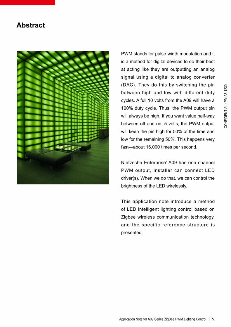
PWM stands for pulse-width modulation and it is a method for digital devices to do their best at acting like they are outputting an analog signal using a digital to analog converter (DAC). They do this by switching the pin between high and low with different duty cycles. A full 10 volts from the A09 will have a 100% duty cycle. Thus, the PWM output pin will always be high. If you want value half-way between off and on, 5 volts, the PWM output will keep the pin high for 50% of the time and low for the remaining 50%. This happens very fast—about 16,000 times per second.
Nietzsche Enterprise’ A09 has one channel PWM output, installer can connect LED driver(s). When we do that, we can control the brightness of the LED wirelessly.
This application note introduce a method of LED intelligent lighting control based on Zigbee wireless communication technology, and the specif ic reference structure is presented.

6. | Application Note for A09 Series ZigBee PWM Lighting Control
CONF
IDEN
TIAL
: PM-
A8-1
230
The system can achieve normal PWM dimming, timing dimming, self-adaptive d i m m i n g a n d m o o d l i g h t i n g w i t h a corresponding human-computer interface, or customized design. This method is more intelligent and humanized than traditional lighting control system.
Combining the sensing technology of lighting control, such as occupancy sensors and daylighting controls, a further 40% energy can be saved. Given these facts, the evolution to LED lighting in homes and offices promises a significant positive environmental impact towards reducing carbon footprint.
ZigBee is the only global standards-based wireless technology designed to address the unique needs of low-cost, low-power wireless sensor and control networks. ZigBee can be used almost anywhere, is easy to implement and needs little power to operate. Dimming LEDs is most commonly done either by lowering the current, or through a technique called Pulsed Width Modulation (PWM). LEDs have a very quick response time (~20 nanoseconds), and instantaneously reach full light output.
Nietzsche Enterprise DeliversCombining dedication to wireless technology and building automation products with
its world-class engineering and mixed-signal design expertise, Nietzsche Enterprise
delivers critical building blocks to its customers, giving them the competitive edge
to succeed in today’s dynamic LED lighting market. Using Nietzsche ZigBee PWM
Output Device, control software and reference usage model, energy efficient LED
lighting for the residential market and easy-to-install smart commercial lighting
systems that provide quick return on investment.
Application Note for A09 Series ZigBee PWM Lighting Control | 7.
CONF
IDEN
TIAL
: PM-
A8-1
230
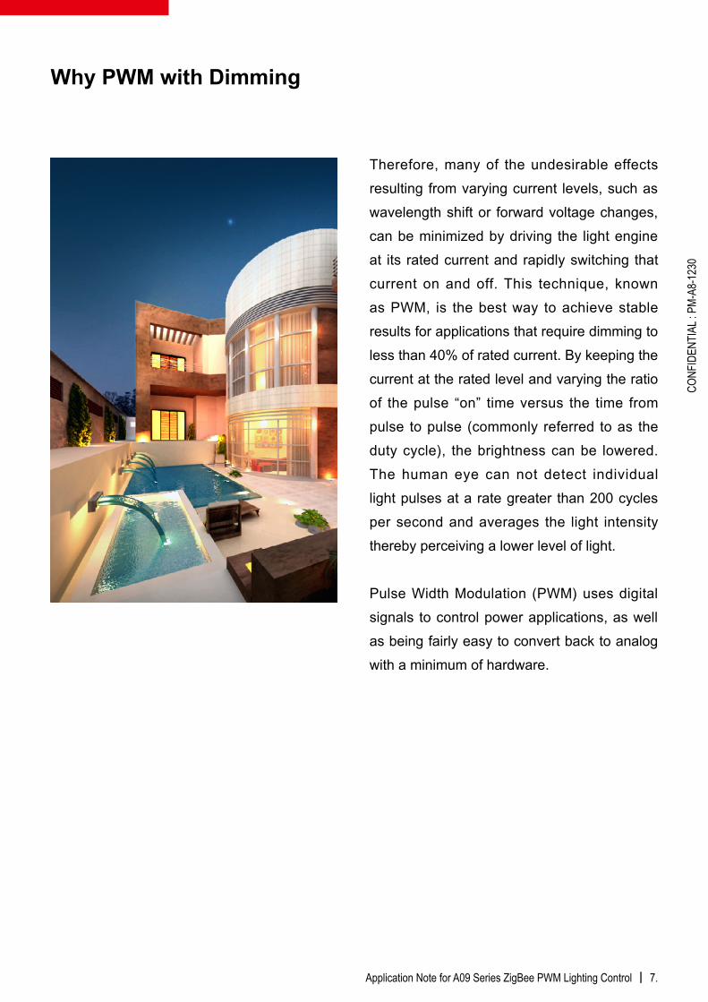
Therefore, many of the undesirable effects resulting from varying current levels, such as wavelength shift or forward voltage changes, can be minimized by driving the light engine at its rated current and rapidly switching that current on and off. This technique, known as PWM, is the best way to achieve stable results for applications that require dimming to less than 40% of rated current. By keeping the current at the rated level and varying the ratio of the pulse “on” time versus the time from pulse to pulse (commonly referred to as the duty cycle), the brightness can be lowered. The human eye can not detect individual light pulses at a rate greater than 200 cycles per second and averages the light intensity thereby perceiving a lower level of light.
Pulse Width Modulation (PWM) uses digital signals to control power applications, as well as being fairly easy to convert back to analog with a minimum of hardware.
Why PWM with Dimming
8. | Application Note for A09 Series ZigBee PWM Lighting Control
CONF
IDEN
TIAL
: PM-
A8-1
230
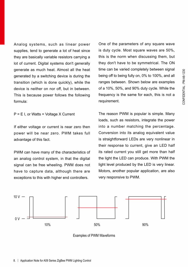
10 V
Analog systems, such as l inear power supplies, tend to generate a lot of heat since they are basically variable resistors carrying a lot of current. Digital systems don't generally generate as much heat. Almost all the heat generated by a switching device is during the transition (which is done quickly), while the device is neither on nor off, but in between. This is because power follows the following formula:
P = E I, or Watts = Voltage X Current
If either voltage or current is near zero then power will be near zero. PWM takes full advantage of this fact.
PWM can have many of the characteristics of an analog control system, in that the digital signal can be free wheeling. PWM does not have to capture data, although there are exceptions to this with higher end controllers.
One of the parameters of any square wave is duty cycle. Most square waves are 50%, this is the norm when discussing them, but they don't have to be symmetrical. The ON time can be varied completely between signal being off to being fully on, 0% to 100%, and all ranges between. Shown below are examples of a 10%, 50%, and 90% duty cycle. While the frequency is the same for each, this is not a requirement.
The reason PWM is popular is simple. Many loads, such as resistors, integrate the power into a number matching the percentage. Conversion into its analog equivalent value is straightforward LEDs are very nonlinear in their response to current, give an LED half its rated current you still get more than half the light the LED can produce. With PWM the light level produced by the LED is very linear. Motors, another popular application, are also very responsive to PWM.
0 V10% 50% 90%
Examples of PWM Waveforms
Application Note for A09 Series ZigBee PWM Lighting Control | 9.
CONF
IDEN
TIAL
: PM-
A8-1
230
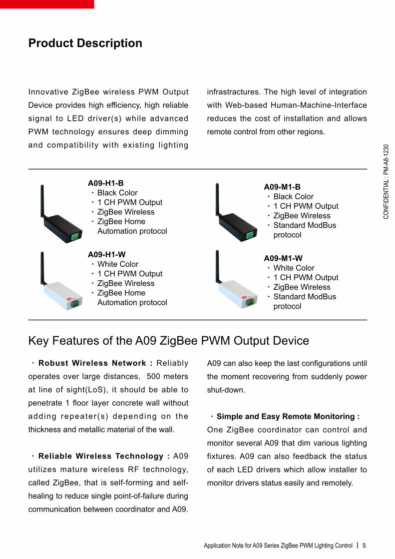
Innovative ZigBee wireless PWM Output Device provides high efficiency, high reliable signal to LED driver(s) while advanced PWM technology ensures deep dimming and compatibi l i ty with exist ing l ighting
Product Description
‧Robust Wireless Network : Reliablyoperates over large distances, 500 meters at line of sight(LoS), it should be able to penetrate 1 floor layer concrete wall without add ing repeater (s) depending on the thickness and metallic material of the wall.
‧Reliable Wireless Technology : A09utilizes mature wireless RF technology, called ZigBee, that is self-forming and self-healing to reduce single point-of-failure during communication between coordinator and A09.
A09-H1-B‧Black Color‧1 CH PWM Output‧ZigBee Wireless‧ZigBee Home
Automation protocol
A09-M1-B‧Black Color‧1 CH PWM Output‧ZigBee Wireless‧Standard ModBus
protocol
A09-M1-W‧White Color‧1 CH PWM Output‧ZigBee Wireless‧Standard ModBus
protocol
A09-H1-W‧White Color‧1 CH PWM Output‧ZigBee Wireless‧ZigBee Home
Automation protocol
A09 can also keep the last configurations until the moment recovering from suddenly power shut-down.
‧Simple and Easy Remote Monitoring :One ZigBee coordinator can control and monitor several A09 that dim various lighting fixtures. A09 can also feedback the status of each LED drivers which allow installer to monitor drivers status easily and remotely.
infrastractures. The high level of integration with Web-based Human-Machine-Interface reduces the cost of installation and allows remote control from other regions.
Key Features of the A09 ZigBee PWM Output Device
10. | Application Note for A09 Series ZigBee PWM Lighting Control
CONF
IDEN
TIAL
: PM-
A8-1
230
‧Remote Control and Scheduling : A09 control can be based on user configurable ON/OFF/DIM schedules programmed on a daily / monthly / yearly / special events basis or customized design.
‧Dimming Control : A09 supports dimming of any LED driver with a PWM input.
‧Power Metering : The whole wireless lighting control infrastructure can be added A08 Energy meter and actuator to feedback energy consumption over one specific LED driver. Therefore, installer can monitor electrical parameters such as Current, Voltage, Power Factor, KW and Kwh.
‧Fault Monitoring : Extens ive fau l t monitoring function can be customized,
that reports lamp burn outs, lamp cycling, ballast failure, over/under voltage, abnormal power consumption, low power factor, communication failure and more. All faults are sent to the Centralized Monitoring Office that generates alarms for visualization and fault rectification.
‧Alarm Call Service : Alarms can be customized that sends directly to relevant users via Emails or Text Messages (SMS) when they occur. Messages are time stamped and contain key parameters associated with the fault/alarm.
‧Burn Hours : The installed can customized controller that keeps track of LED driver burn hours for predictive maintenance, allowing pro-active lamp replacement.
Application Note for A09 Series ZigBee PWM Lighting Control | 11.
CONF
IDEN
TIAL
: PM-
A8-1
230
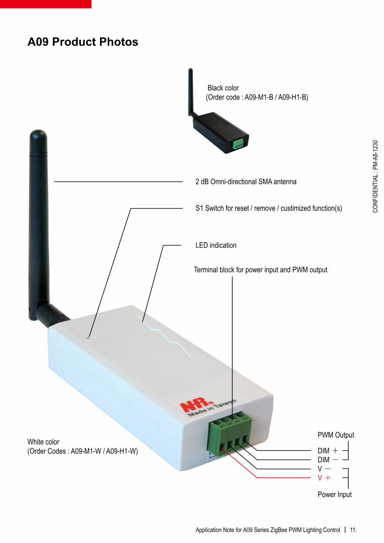
A09 Product Photos
2 dB Omni-directional SMA antenna
S1 Switch for reset / remove / custimized function(s)
LED indication
Terminal block for power input and PWM output
Black color(Order code : A09-M1-B / A09-H1-B)
White color(Order Codes : A09-M1-W / A09-H1-W) DIM +
DIM -V -V +
PWM Output
Power Input

12. | Application Note for A09 Series ZigBee PWM Lighting Control
CONF
IDEN
TIAL
: PM-
A8-1
230
Ordering Codes A09-M1-W A09-M1-B A09-H1-W A09-H1-BNetwork Protocol Modbus RTU ZigBee Home AutomationColor White Black White BlackPWM Channel 1 CH 1 CH 1CH 1 CHDimming Mode PWMPWM Output Frequency 300Hz ~ 20KHzPWM Duty Cycle 0 ~ 100%PWM Voltage DC 0V for low level – 10V for high levelDimming Load Capacity 1000 mAWireless Protocol IEEE 802.15.4 Zigbee2007/PRO HATransmission Range 500 meters / 1640 feet (Free Space)Operating Frequency 2.4GHz ISM BandRF Output Power 18dBmReceiver Sensitivity -92dBmPower Consumption 0.8WNetwork Topology Star / Tree / MeshPower Supply DC 12V ~ 24VOperating Temperature -10 °C ~ 50 °C (32°F ~ 104°F)Input and output connections Screw terminal AWG 16 max.Color White (standard), BlackDimensions 62mm(L) x 42mm(W) x 15mm(H)Weight 50.4g / 1.78ozOperating System Windows 95 ~ Win 8Addressing HA:IEEE MAC 64Bit / Modbus: IDCertifications CE/FCC/RoHS
A09 Series Specificatio

Application Note for A09 Series ZigBee PWM Lighting Control | 13.
CONF
IDEN
TIAL
: PM-
A8-1
230
V+
V-
DIM+
DIM-PWM OUTPUT
POWER INPUT
LED DriverACLACNGND
V-V+
DIM-DIM+
POWER SUPPLYDC 12V
.
.
....
.
.
.
TO D
IMM
ER
PW
M IN
PU
TTO
LO
AD
DC
OU
TPU
T
PO
WE
R IN
PU
T
...
...
V-
V+
V-
V+
LED LIGHT / FIXTURE#
LED DRIVER CONNECT WITH A09 DIAGRAM
A09 ZigBee PWM Output Device
LED Driver Wiring with A09 Diagram
A09 Terminal Block Dimension

14. | Application Note for A09 Series ZigBee PWM Lighting Control
CONF
IDEN
TIAL
: PM-
A8-1
230
Procedure Action LED indicationDuring Installation
Step1 - Reset device Press and hold S1 for 5 seconds on ZPOD*
‧ Resetting : Red LED and Blue LED flash simultaneously for 2 seconds‧ After reset : Blue LED flashes once every 5 seconds(No-joined mode)
Step2 - Join device Press S1 for 1 seconds on Coordinator*
‧Joining : Blue LED flashes 3 times‧Joined : Blue LED flashes once every 2 seconds
Remove ZPOD* from current PAN*
‧ Press S1 for 3 times on Coordinator‧ Press S1 for 2 times on ZPOD*
Remove : Red LED quickly flashes until remove completion, and go to No-joined mode
During Operation
Set ON Operates on HMI* A09 Receiving ON command : Red LED flashes once
Set OFF Operates on HMI* A09 Receiving OFF command : Red LED flashes twice
Adjust Duty Cycle(%) Operates on HMI* Adjust Duty Cycle/brightness : Red LED flashes once
Definition :
*ZPOD : ZigBee PWM Output Device
*Coordinator : Installer need to choose proper coordinator to meet the need of field applicatoin. Each coordinator has its own position and type of S1. Please check manual of each type for more details.
*ON command is “Previous-set” value of Duty Cycle/Frequency(%)
*OFF command is “Zero” value of Duty Cycle/Frequency(%)
*PAN : Personal Area Network referring to the wireless network
*HMI : Human Machine Interface referring to Software on Notebook PC, Point-of-sale PC, Programmable Logic Controller, Smart devices…etc.
The photo demonstrates how to pressS1 switch with bended paperclip.
Operation Procedure & LED Indication
Application Note for A09 Series ZigBee PWM Lighting Control | 15.
CONF
IDEN
TIAL
: PM-
A8-1
230
LED Driver
Notebook PC
Industrial PC
PLCA09
ZigBee USBDongle
LED Lights
LED Lights
LED Lights
LED Lights
LED Driver
LED Driver
LED Driver
A09
A09
A09
Desktop PC
Wireless Lighting Control By Local PC / PLC
Application Structure
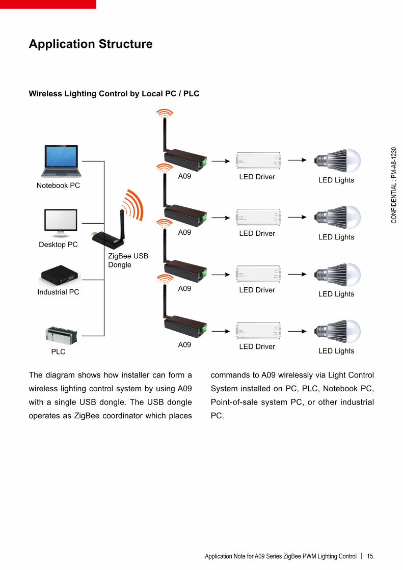
The diagram shows how installer can form a wireless lighting control system by using A09 with a single USB dongle. The USB dongle operates as ZigBee coordinator which places
commands to A09 wirelessly via Light Control System installed on PC, PLC, Notebook PC, Point-of-sale system PC, or other industrial PC.
Wireless Lighting Control by Local PC / PLC
16. | Application Note for A09 Series ZigBee PWM Lighting Control
CONF
IDEN
TIAL
: PM-
A8-1
230
LED Driver
Notebook PC
Tablet PC
Smart Phones
A09 ZigBee 3G/ WiFi / EthernetGateway Controller LED Lights
LED Lights
LED Lights
LED Lights
LED Driver
LED Driver
LED Driver
A09
A09
A09
Desktop PC
Wireless Lighting Control & Energy Management By Remote Smart Devices
ZigBeeEnergy Meter
Company Cloud Database
ZigBee EthernetGateway
Wireless Lighting Control & Energy Management by Remote Smart Devices
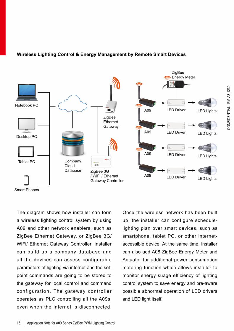
The diagram shows how installer can form a wireless lighting control system by using A09 and other network enablers, such as ZigBee Ethernet Gateway, or ZigBee 3G/ WiFi/ Ethernet Gateway Controller. Installer can build up a company database and all the devices can assess configurable parameters of lighting via internet and the set-point commands are going to be stored to the gateway for local control and command conf igurat ion. The gateway contro l ler operates as PLC controlling all the A09s, even when the internet is disconnected.
Once the wireless network has been built up, the installer can configure schedule-lighting plan over smart devices, such as smartphone, tablet PC, or other internet-accessible device. At the same time, installer can also add A08 ZigBee Energy Meter and Actuator for additional power consumption metering function which allows installer to monitor energy suage efficiency of lighting control system to save energy and pre-aware possible abnormal operation of LED drivers and LED light itself.
Application Note for A09 Series ZigBee PWM Lighting Control | 17.
CONF
IDEN
TIAL
: PM-
A8-1
230
Light Control System(LCS) PC Software Set-up for Dimming
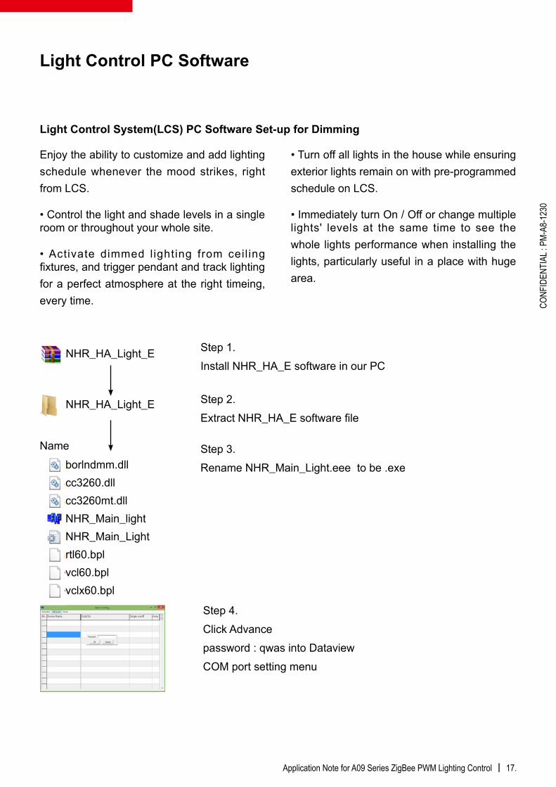
Step 3. Rename NHR_Main_Light.eee to be .exe
Step 1.Install NHR_HA_E software in our PC
Step 2. Extract NHR_HA_E software file
Step 4.Click Advancepassword : qwas into DataviewCOM port setting menu
Enjoy the ability to customize and add lighting schedule whenever the mood strikes, right from LCS.
• Control the light and shade levels in a single room or throughout your whole site.
• Activate dimmed l ighting from ceil ing fixtures, and trigger pendant and track lighting for a perfect atmosphere at the right timeing, every time.
• Turn off all lights in the house while ensuring exterior lights remain on with pre-programmed schedule on LCS.
• Immediately turn On / Off or change multiple lights' levels at the same time to see the whole lights performance when installing the lights, particularly useful in a place with huge area.
NHR_HA_Light_E
NHR_HA_Light_E
borlndmm.dllcc3260.dllcc3260mt.dllNHR_Main_lightNHR_Main_Lightrtl60.bplvcl60.bplvclx60.bpl
Name
Light Control PC Software

18. | Application Note for A09 Series ZigBee PWM Lighting Control
CONF
IDEN
TIAL
: PM-
A8-1
230
To name device; set light duty %, choose area; manually On / Off
To scheduling light timing
Single On / Off control or Automatically group control

Application Note for A09 Series ZigBee PWM Lighting Control | 19.
CONF
IDEN
TIAL
: PM-
A8-1
230
1. Can I split a single Zigbee PWM Output Device to drive multiple LED drivers (Buck pack)? Yes, you can do this. First of all, you need to know what LED Driver you will use and how many such drivers you will use. For getting to know what LED Driver you are dealing with, please check driver datasheet about relevant information such as the current draw on the PWM input; input resistance to the driver; or requirement of output resistance from the previous device. If none of the above-mentioned information has been shown, then please go to their sales representative for further support. For how many such derivers you will use, please do NOT exceed Dimming Load Current in total for the direct connection from any one pin. For A09, the Dimming Load Current is 1000 mA. Therefore, in this case A09 is capable of driving 10 LED drivers at maximum with current draw at 100 mA. Note : If two different drivers will track identically over the 0-100% PWM range. That is a 50% PWM output may not give you 50% brightness when using two different driver modules wired to their LEDs. You can only try it and see if that might be a visual problem or not.
2. How many LED lights can single LED driver accommodate? Driving single LED light sources in non-dimming applications is relatively simple. A constant-current driver is chosen to deliver the desired current, with enough forward voltage output to accommodate the maximum input voltage of the LED source. LED light sources are not designed to be driven with a reverse voltage. Driving multiple LED light sources with one driver is generally done with the LEDs arranged in series strings to avoid uneven light levels resulting from voltage variations. When selecting a series string driver, the output voltage should be high enough to accommodate the sum of the maximum input voltages of LED light sources. Determine the number of low voltage outputs of the driver when installing multiple PWM controllers/dimmer switches. No more than one PWM controller/dimmer switch can be attached to a single output of the driver. Appropriated loading of each element in an LED lighting system is vital. First of all, choosing an driver for use with a fixture must ensure that the LED light load is less than the driver’s maximum rating (typically in amps, volts, and/or watts), “AND” is greater than the driver’s minimum rating. The LED driver may function intermittently, or fail prematurely, if that is not properly loaded. Installer must check rated power of LED driver, and ensure it covers the Watt of LED lights in total. It is recommended to load the driver no more than 80% its labeled rating for maximum longevity.
FAQ

© 2015 Nietzsche Enterprise Co., Ltd. All rights reserved. Sentrol Cloud is registered trade mark that Nietzsche Enterpriser owns as sensor cloud service pllarform. No part of the contents of this manual may be transmitted or reproduced in any form or by any means without the written permission of Nietzsche Enterprise Co., Ltd. The content expressed in this document can be changed without notification.
PM-A8-1230
Nietzsche Enterprise Co., Ltd. (NHR), est. 1978, is an ISO9001 certified manufacturer, has been engaged in wireless communication and power solutions for over 36 years and continues to focus on meeting current and future market needs in Wireless Sensing Network. NHR's design center and factory are in Taipei, Taiwan, with a commitment to solving constraints from wires and cables through delivering intuitive, convenient, reliable, and rapid return on investment wireless solutions to customers. Products and solutions include agriculture, logistics/transportation, energy & water management, security & maintenance, industrial, asset management, and aquatic.
SentrolCloud is a sensor cloud platform for Automated Control and Instant Out-limit Alert. Using a world-leading cloud storage service provider to ensure the data is secure and always accessible from anywhere via any web-enabled computer, tablet, or smart phone, SentrolCloud interface puts intuitive monitoring and control at your fingertips allowing for 1-second rapid decision-making and more in-depth trend analysis. For more information, visit our cloud platform at www.sentrolcloud.com
www.shop-wifi.com/wireless-sensors
e-mail: [email protected]


![AT08550: ZigBee Attribute Reporting · ZigBee Attribute Reporting [APPLICATION NOTE] Atmel-42334A-ZigBee-Attribute-Reporting -ApplicationNote_012015 3 1 Overview The ZigBee Specification](https://static.fdocuments.in/doc/165x107/5f43d267b58b3c15740a0db6/at08550-zigbee-attribute-reporting-zigbee-attribute-reporting-application-note.jpg)