A001 4X270 MW BHADRADRI TPS VOLUME II B … · VENTILAION SYSTEM LIST OF TOOLS AND TACKELS ......
47
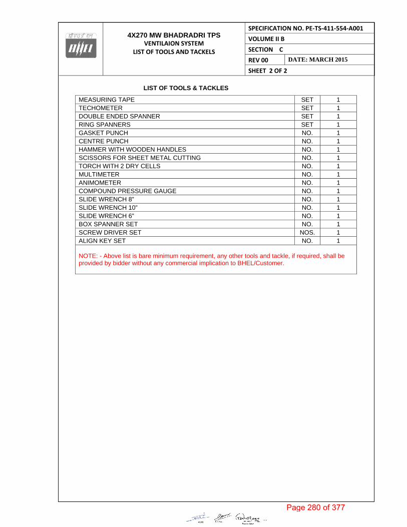
4X270 MW BHADRADRI TPS VENTILAION SYSTEM LIST OF TOOLS AND TACKELS SPECIFICATION NO. PE‐TS‐411‐554‐A001 VOLUME II B SECTION C REV 00 DATE: MARCH 2015 SHEET 2 OF 2 LIST OF TOOLS & TACKLES MEASURING TAPE SET 1 TECHOMETER SET 1 DOUBLE ENDED SPANNER SET 1 RING SPANNERS SET 1 GASKET PUNCH NO. 1 CENTRE PUNCH NO. 1 HAMMER WITH WOODEN HANDLES NO. 1 SCISSORS FOR SHEET METAL CUTTING NO. 1 TORCH WITH 2 DRY CELLS NO. 1 MULTIMETER NO. 1 ANIMOMETER NO. 1 COMPOUND PRESSURE GAUGE NO. 1 SLIDE WRENCH 8” NO. 1 SLIDE WRENCH 10” NO. 1 SLIDE WRENCH 6” NO. 1 BOX SPANNER SET NO. 1 SCREW DRIVER SET NOS. 1 ALIGN KEY SET NO. 1 NOTE: - Above list is bare minimum requirement, any other tools and tackle, if required, shall be provided by bidder without any commercial implication to BHEL/Customer. Page 280 of 377
Transcript of A001 4X270 MW BHADRADRI TPS VOLUME II B … · VENTILAION SYSTEM LIST OF TOOLS AND TACKELS ......
4X270 MW BHADRADRI TPS
VENTILAION SYSTEM LIST OF TOOLS AND TACKELS
SPECIFICATION NO. PE‐TS‐411‐554‐A001
VOLUME II B
SECTION C
REV 00 DATE: MARCH 2015
SHEET 2 OF 2
LIST OF TOOLS & TACKLES
MEASURING TAPE SET 1 TECHOMETER SET 1 DOUBLE ENDED SPANNER SET 1 RING SPANNERS SET 1 GASKET PUNCH NO. 1 CENTRE PUNCH NO. 1 HAMMER WITH WOODEN HANDLES NO. 1 SCISSORS FOR SHEET METAL CUTTING NO. 1 TORCH WITH 2 DRY CELLS NO. 1 MULTIMETER NO. 1 ANIMOMETER NO. 1 COMPOUND PRESSURE GAUGE NO. 1 SLIDE WRENCH 8” NO. 1 SLIDE WRENCH 10” NO. 1 SLIDE WRENCH 6” NO. 1 BOX SPANNER SET NO. 1 SCREW DRIVER SET NOS. 1 ALIGN KEY SET NO. 1 NOTE: - Above list is bare minimum requirement, any other tools and tackle, if required, shall be provided by bidder without any commercial implication to BHEL/Customer.
Page 280 of 377

SPECIFICATION NO. PE-TS- 411-554-A-001
TECHNICAL SPECIFICATION VOLUME II B
FOR VENTILATION SYSTEM SECTION C
4 X 270 MW BHADRADRI TPS, REV 00 MARCH 2015
SHEET 1 OF 2
PE
M-6
666-
0
ANNEXURE- V
DRAWING AND DOCUMENTS SUBMISSION PROCEDURE
Page 281 of 377

Tela
ngan
a St
ate
Pow
er G
ener
atio
n C
orpo
ratio
n Lt
d.
EPC
Bid
Doc
umen
t1x
800
MW
Kot
hagu
dem
TPS
e-
PCT/
TS/K
/02/
2014
-15
DEV
ELO
PMEN
T C
ON
SULT
ANTS
V.IIA
/S-6
Anx-
1:1
(e-P
CT-
TS-K
-02-
2014
-15-
Vol.
IIA-6
Ann
x.do
cx)
AN
NEX
UR
E-1
DIS
TRIB
UTI
ON
SC
HED
ULE
S. No
Des
crip
tion
TSG
ENC
OM
/S D
CP
L, K
OLK
ATA
Equi
pmen
t Ve
ndor
Rem
arks
Dire
ctor
Proj
ects
Dire
ctor
Te
chni
cal
CE/C
ivil
Ther
mal
Proj
ects
H
yd.
CE/
TPC-
I,H
ydCE
/ O
&M
/KT
PS
SE/
Civi
lKT
PS
SE/E
&M
/KT
PSD
E Co
nstr
. KT
PS
Kolk
ata
HYD
KTPS
ALe
tter
Of
Inte
nt
or
Con
trac
t D
ocu
men
ts1
11
S1
22
11
11
2
BV
endo
r D
raw
ings
1.Pr
elim
inar
y1
11
21
12
212
1-
S2.
Retu
rn p
relim
inar
y w
ith
com
men
ts-
-1
21
11
1S
1-
1
3.Fi
nal a
nd a
ny r
evis
ion
ther
eof
a. C
ivil
11
6+1T
11
6+1T
1-
2+1T
11
Sb.
E&
M1
11
6+1T
11
6+1T
12+
1T1
1S
C.D
esig
n D
raw
ings
1.Pr
elim
inar
ya.
Civ
il1
12
11
21
14
11
Sb.
E&
M1
11
21
12
14
11
S2.
Rele
ased
for
con
stru
ctio
na.
Civ
il1
12
11
61
11
12
Sb.
E&
M1
11
12
16
11
12
S3.
Retu
rn m
arke
d ‘A
s bu
ilt’
a. C
ivil
--
1-
-1
--
11
S1
b. E
&M
--
-1
--
11
11
S1
4.As
bui
lt dr
awin
gsa.
Civ
il-
-1+
1T-
2+1T
5+1T
-1
1+1T
-1
Sb.
E&
M-
-1
2+1T
2+1T
-5+
1T1+
1T1+
1T-
1S
CO
NS
ULT
AN
T
Page 282 of 377

Tela
ngan
a St
ate
Pow
er G
ener
atio
n C
orpo
ratio
n Lt
d.
EPC
Bid
Doc
umen
t1x
800
MW
Kot
hagu
dem
TPS
e-
PCT/
TS/K
/02/
2014
-15
DEV
ELO
PMEN
T C
ON
SULT
ANTS
V.IIA
/S-6
Anx-
1:2
(e-P
CT-
TS-K
-02-
2014
-15-
Vol.
IIA-6
Ann
x.do
cx)
S. No
Des
crip
tion
TSG
ENC
OM
/S D
CP
L, K
OLK
ATA
Equi
pmen
t Ve
ndor
Rem
arks
Dire
ctor
Proj
ects
Dire
ctor
Te
chni
cal
CE/C
ivil
Ther
mal
Proj
ects
H
yd.
CE/
TPC-
I,H
ydCE
/ O
&M
/KT
PS
SE/
Civi
lKT
PS
SE/E
&M
/KT
PSD
E Co
nstr
. KT
PS
Kolk
ata
HYD
KTPS
DPr
ogre
ss R
epor
t M
onth
ly1.
Equi
pmen
t ve
ndor
11
12
11
21
11
1S
2.M
/s D
CPL,
Kol
kata
11
22
11
21
S1
1N
ilE
Test
& I
nspe
ctio
n Re
port
s1.
Equi
pmen
t m
anuf
actu
rer
a. C
ivil
11
12
11
1-
111
1S
sb.
E&
M1
1-
21
-1
111
11
S2.
M/s
DCP
L, K
olka
ta1
1-
21
-1
1S
-1
-F
Inst
ruct
ion
Man
uals
/Dat
a Bo
oks
1.Eq
uipm
ent
man
ufac
ture
ra.
Civ
il1
11+
1T1
16+
1T1
12+
1T1
1S
b. E
&M
11
-3+
1T1
-6+
1T2
3+1T
11
S2.
M/s
DCP
L, K
olka
ta1
1-
10+
1T1
-15
+1T
-S
11
Nil
GM
/s D
CPL,
Kol
kata
Crite
ria1
11
8+1T
11
21
11
1S
HD
esig
n Ca
lcul
atio
ns1
11
8+1T
11
21
11
1S
IFi
nal c
onsu
lting
En
gine
erin
g Re
port
11
110
11
21
S1
1N
il
S–
Sour
ce, T
–Tr
ansp
aren
cy &
Sof
t Co
py o
n CD
,
TSG
ENCO
:Te
lang
ana
Stat
ePo
wer
Gen
erat
ion
Corp
orat
ion
Lim
ited
Dire
ctor
, Pro
ject
s, H
yd:
Dire
ctor
/ Pr
ojec
ts, T
SGEN
CO, V
idyu
t So
udha
, Hyd
erab
ad –
500
082
CO
NS
ULT
AN
T
Page 283 of 377
Tela
ngan
a St
ate
Pow
er G
ener
atio
n C
orpo
ratio
n Lt
d.
EPC
Bid
Doc
umen
t1x
800
MW
Kot
hagu
dem
TPS
e-
PCT/
TS/K
/02/
2014
-15
DEV
ELO
PMEN
T C
ON
SULT
ANTS
V.IIA
/S-6
Anx-
1:3
(e-P
CT-
TS-K
-02-
2014
-15-
Vol.
IIA-6
Ann
x.do
cx)
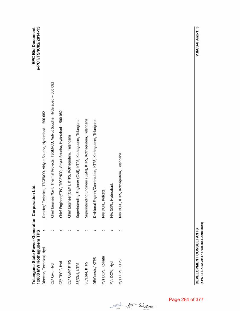
Dire
ctor
, Tec
hnic
al, H
yd:
Dire
ctor
/Te
chni
cal,
TSG
ENCO
, Vid
yut
Soud
ha,
Hyd
erab
ad –
500
082
CE/
Civi
l, H
yd:
Chie
f En
gine
er/C
ivil,
The
rmal
Pro
ject
s, T
SGEN
CO, V
idyu
t So
udha
, Hyd
erab
ad –
500
082
CE/
TPC-
I, H
yd:
Chie
f En
gine
er/T
PC,T
SGEN
CO, V
idyu
t So
udha
, H
yder
abad
–50
0 08
2
CE/
O&
M/
KTPS
:Ch
ief
Engi
neer
(O&
M),
KTP
S,Ko
thag
udem
, Tel
anga
na
SE/C
ivil,
KTP
S:
Supe
rinte
ndin
g En
gine
er (
Civi
l), K
TPS,
Kot
hagu
dem
, Tel
anga
na
SE/E
&M
, KTP
S:
Supe
rinte
ndin
g En
gine
er (
E&M
), K
TPS,
Kot
hagu
dem
, Tel
anga
na
DE/
Cons
tr./
KTPS
: D
ivis
iona
l Eng
iner
/Con
strc
utio
n, K
TPS,
Kot
hagu
dem
, Tel
anga
na
M/s
DCP
L,Ko
lkat
a:
M/s
DCP
L, K
olka
ta.
M/s
DCP
L, H
yd:
M/s
DCP
L,H
yder
abad
.
M/s
DCP
L,KT
PS:
M/s
DCP
L,KT
PS, K
otha
gude
m, T
elan
gana
Page 284 of 377
6044417
Text Box

TECHNICAL SPECIFICATION 4X270 MW BHADRADRI TPS
SPECIFICATION NO.PE-TS-411-554-A001
VOLUME II B
SECTION C
REV. 00 DATE: MARCH 2015
ANNEXURE: VI
MASTER DRAWING LIST WITH SCHEDULE OF SUBMISSION (MDL)
Page 285 of 377
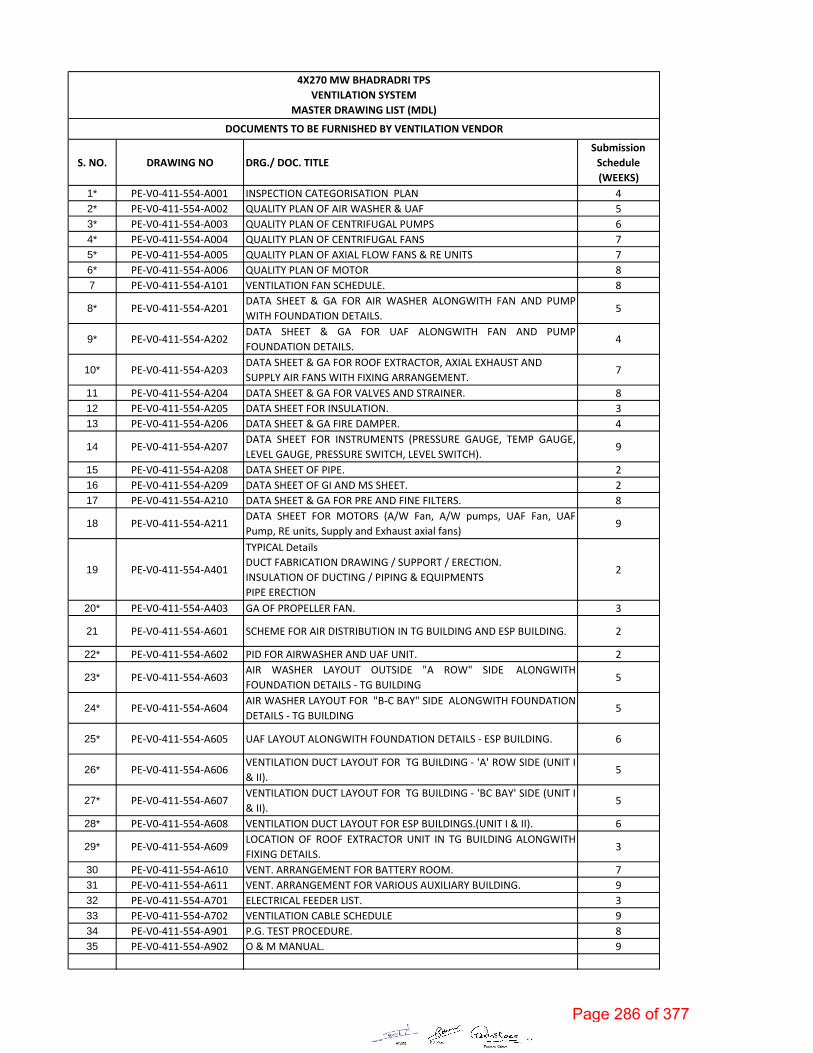
S. NO. DRAWING NO DRG./ DOC. TITLE
Submission
Schedule
(WEEKS)
1* PE‐V0‐411‐554‐A001 INSPECTION CATEGORISATION PLAN 4
2* PE‐V0‐411‐554‐A002 QUALITY PLAN OF AIR WASHER & UAF 5
3* PE‐V0‐411‐554‐A003 QUALITY PLAN OF CENTRIFUGAL PUMPS 6
4* PE‐V0‐411‐554‐A004 QUALITY PLAN OF CENTRIFUGAL FANS 7
5* PE‐V0‐411‐554‐A005 QUALITY PLAN OF AXIAL FLOW FANS & RE UNITS 7
6* PE‐V0‐411‐554‐A006 QUALITY PLAN OF MOTOR 8
7 PE‐V0‐411‐554‐A101 VENTILATION FAN SCHEDULE. 8
8* PE‐V0‐411‐554‐A201DATA SHEET & GA FOR AIR WASHER ALONGWITH FAN AND PUMP
WITH FOUNDATION DETAILS.5
9* PE‐V0‐411‐554‐A202DATA SHEET & GA FOR UAF ALONGWITH FAN AND PUMP
FOUNDATION DETAILS.4
10* PE‐V0‐411‐554‐A203DATA SHEET & GA FOR ROOF EXTRACTOR, AXIAL EXHAUST AND
SUPPLY AIR FANS WITH FIXING ARRANGEMENT.7
11 PE‐V0‐411‐554‐A204 DATA SHEET & GA FOR VALVES AND STRAINER. 8
12 PE‐V0‐411‐554‐A205 DATA SHEET FOR INSULATION. 3
13 PE‐V0‐411‐554‐A206 DATA SHEET & GA FIRE DAMPER. 4
14 PE‐V0‐411‐554‐A207DATA SHEET FOR INSTRUMENTS (PRESSURE GAUGE, TEMP GAUGE,
LEVEL GAUGE, PRESSURE SWITCH, LEVEL SWITCH).9
15 PE‐V0‐411‐554‐A208 DATA SHEET OF PIPE. 2
16 PE‐V0‐411‐554‐A209 DATA SHEET OF GI AND MS SHEET. 2
17 PE‐V0‐411‐554‐A210 DATA SHEET & GA FOR PRE AND FINE FILTERS. 8
18 PE‐V0‐411‐554‐A211DATA SHEET FOR MOTORS (A/W Fan, A/W pumps, UAF Fan, UAF
Pump, RE units, Supply and Exhaust axial fans)9
19 PE‐V0‐411‐554‐A401
TYPICAL Details
DUCT FABRICATION DRAWING / SUPPORT / ERECTION.
INSULATION OF DUCTING / PIPING & EQUIPMENTS
PIPE ERECTION
2
20* PE‐V0‐411‐554‐A403 GA OF PROPELLER FAN. 3
21 PE‐V0‐411‐554‐A601 SCHEME FOR AIR DISTRIBUTION IN TG BUILDING AND ESP BUILDING. 2
22* PE‐V0‐411‐554‐A602 PID FOR AIRWASHER AND UAF UNIT. 2
23* PE‐V0‐411‐554‐A603AIR WASHER LAYOUT OUTSIDE "A ROW" SIDE ALONGWITH
FOUNDATION DETAILS ‐ TG BUILDING 5
24* PE‐V0‐411‐554‐A604AIR WASHER LAYOUT FOR "B‐C BAY" SIDE ALONGWITH FOUNDATION
DETAILS ‐ TG BUILDING 5
25* PE‐V0‐411‐554‐A605 UAF LAYOUT ALONGWITH FOUNDATION DETAILS ‐ ESP BUILDING. 6
26* PE‐V0‐411‐554‐A606VENTILATION DUCT LAYOUT FOR TG BUILDING ‐ 'A' ROW SIDE (UNIT I
& II).5
27* PE‐V0‐411‐554‐A607VENTILATION DUCT LAYOUT FOR TG BUILDING ‐ 'BC BAY' SIDE (UNIT I
& II).5
28* PE‐V0‐411‐554‐A608 VENTILATION DUCT LAYOUT FOR ESP BUILDINGS.(UNIT I & II). 6
29* PE‐V0‐411‐554‐A609LOCATION OF ROOF EXTRACTOR UNIT IN TG BUILDING ALONGWITH
FIXING DETAILS.3
30 PE‐V0‐411‐554‐A610 VENT. ARRANGEMENT FOR BATTERY ROOM. 7
31 PE‐V0‐411‐554‐A611 VENT. ARRANGEMENT FOR VARIOUS AUXILIARY BUILDING. 9
32 PE‐V0‐411‐554‐A701 ELECTRICAL FEEDER LIST. 3
33 PE‐V0‐411‐554‐A702 VENTILATION CABLE SCHEDULE 9
34 PE‐V0‐411‐554‐A901 P.G. TEST PROCEDURE. 8
35 PE‐V0‐411‐554‐A902 O & M MANUAL. 9
4X270 MW BHADRADRI TPS
VENTILATION SYSTEM
MASTER DRAWING LIST (MDL)
DOCUMENTS TO BE FURNISHED BY VENTILATION VENDOR
Page 286 of 377

S. NO. DRAWING NO DRG./ DOC. TITLE
Submission
Schedule
(WEEKS)
Notes
1
2
3
4
5
6
7
(a)
(b)
(c)
(d)
(e)
(f)
(g)
(h)
(i)
(j)
(k)
(l)
(m)
Submission schedule (Week) is from date of LOI to Package vendor.
The drawings/ documents submitted by vendor shall be complete in all respects with revised drawing submitted incorporating all comments. Any incomplete drawing submitted shall be treated as non-submission with delays attributable to vendor’s account. For any clarification/discussion required to complete the drawings, the bidder shall himself depute his personal to BHEL / Customer’s place any number of time as per the requirement for across the table discussions/ finalizations/ submissions of drawings
Star marked (*) documents shall be treated as basic Engineering documents.
All drawings shall be prepared as per BHEL's title block and shall bear BHEL's drawing No.
The above drawing list is tentative and shall be finalized with the successful bidder after placement of order. While some of the drawings indicated above may not be applicable, some additional drawings may also be required based on scope of work.
Drawings shall be prepared in Auto-Cad latest edition. Required no. of hard and soft copies (editable) of the drawings shall be furnished as per requirement specified elsewhere in the specification.
Only manual calculation with authentic supporting literature (e.g. extracts of hand Book/ standard/codes) shall be acceptable. All design calculations and drawings shall be in SI system only.
All the drawings and documents including general arrangement drawing, data sheet, calculation etc. to be furnished to the customer during detailed engineering stage shall include / indicate the following details for clarity w.r.t. Inspection, construction, erection and maintenance etc.:-
All drawings and documents shall indicate the list of all reference drawings including general arrangement.
All drawings shall include / show plan, elevation, side view, cross - section, skin section, blow - up view; all major self-manufactured and bought out items shall be labeled and included in BOQ / BOM in tabular form.
Schedule of drawings submissions, comment incorporations & approval shall be as stipulated in the specifications. The successful bidder shall depute his design personnel to BHEL’s/ Customer’s/ Consultant’s office for across the table resolution of issues and to get documents approved in the stipulated time.
Bidder to follow the following the drawing submission schedule:
1st submission of drawings from date of LOI as per the submission schedule.
Every revised submission incorporating comments – within 7 days.
Bidder to submit revised drawings complete in all respects incorporating all comments. Any incomplete drawing submitted shall be treated as non-submission with delays attributable to bidder’s account. For any clarification/ discussion required to complete the drawings, the bidder shall himself depute his personal to BHEL for across the table discussions/ finalizations/ submissions of drawings.
Painting schedule shall also be made as a part of general arrangement drawing of each equipment / items indicating at least 3 trade names.
All the drawings required to be furnished to customer during detailed engineering stage shall include technical parameters, details of paints and lubrication, hardness and BOQ / BOM in tabular form indicating all major components including bought out items and their quantity, material of construction indicating its applicable code / standard, weight, make etc.
Drawings/ documents to be submitted for purchasers review/ approval shall be under Revision A, B, C… etc. while drawings /documents to be submitted thereafter for customer’s approval after purchaser’s approval shall be under R-0, 1, 2, 3 ….etc.
Drawings and documents not covered above but required to check safety of machines/ system, shall be submitted during detailed engineering stage without any commercial implication.
All drawings shall include "B.O.M" and indicate quantity, material of construction, make along with IS/BS No., Technical parameters, dimensions, hardness, machining symbol and tolerance, requirement of radiography and hydraulic tests, painting details, elevation, side view, plan, skin section and blow-up view for clarity.
Page 287 of 377

TECHNICAL SPECIFICATION 4X270 MW BHADRADRI TPS
SPECIFICATION NO.PE-TS-411-554-A001
VOLUME II B
SECTION C
REV. 00 DATE: MARCH 2015
ANNEXURE: VII
FORMAT FOR OPERATION AND MAINTENANCE MANUAL
Page 288 of 377

Page 1 of 3
Format for Operation & Maintenance Manual Project name :
Project number :
Package Name :
PO reference :
Document number :
Revision number :
Sl.no. & Sections
Description Tick ( √ )if included in Manual
Remarks
Yes No Not Applicable
1. Cover page
1.1 Project Name
1.2 Customer/consultant Name
1.3 Name of Package
1.4 Supplier details with phone, FAX ,email address , Emergency Contact number
1.5 Name and sign of prepared by , checked by & approved by
1.6 Revision history with approval Details
2.0 Index
2.1 showing the sections & related page nosAll the pages should be numbered section wise
3.0 Description of Plant/System
3.1 Description /write up of operating principle of system equipment/ associated sub‐systems & accessories/controls system , operating conditions, performance parameters under normal , start up and special cases
3.2 Equipment list and basic parameter with Tag numbers
3.3 Data sheets approved by Customer/for information and catalogues provided by original manufacturer
3.4 Associated other packages and Interface /terminal points
3.5 P&ID & Process Diagrams
3.6 GA Layout drawings, As‐built drawings , Actual photograph of items/system (Drawings of A2 & bigger sizes are to be attached in the last)
3.7 Single line/wiring diagrams
3.8 Control philosophy /control write‐ups
4.0 Commissioning Activities (if not covered in separate document i.e. erection
Page 289 of 377

Page 2 of 3
manual, commissioning manual)4.1 Pre‐Commissioning Checks
4.2 handling of items at site
4.3 Storage at site
4.4 Unpacking & Installation procedure
5.0 Operation Guidelines for plant personal/user/operator
5. 1 Interlock & Protection logic along with the limiting values of protection settings for the equipment along with brief philosophy behind the logic, drawings etc. to be provided.
5. 2 Start up, normal operation and shut down procedure for equipments along with the associated systems in step by step mode. Valve sequence chart, step list, interlocks etc. with Equipment isolating procedures to be mentioned.
5. 3 Do’s & Don’t of the equipments.
5. 4 Safety precautions to be taken during normal operation. Safety symbols, Emergency instructions on total power failure condition/lubrication failure/any other condition
5. 5 Parameters to be monitored with normal values and limiting values
5. 6 Trouble shooting with causes and remedial measures
5. 7 Routine operational checks, recommended logs & records
5. 8 Changeover schedule if more than one auxiliary for the same purpose is given
5. 9 Painting requirement and schedule
5. 10 Inspection, repair , Testing and calibration procedures
6.0 Maintenance guidelines for plant personal
6.1 List of Special Tools and Tackles required for Overhaul/Trouble shooting including special testing equipment required for calibration etc.
6.2 Stepwise dismantling and re‐assembly procedure clearly specifying the tools to be used, checks to be made, records to be maintained, clearances etc. to be mentioned. Tolerances for fitment of various components to be given.
6.3 Preventive Maintenance & Overhauling schedules linked with running hours/calendar period along with checks to be given
Page 290 of 377
Page 3 of 3
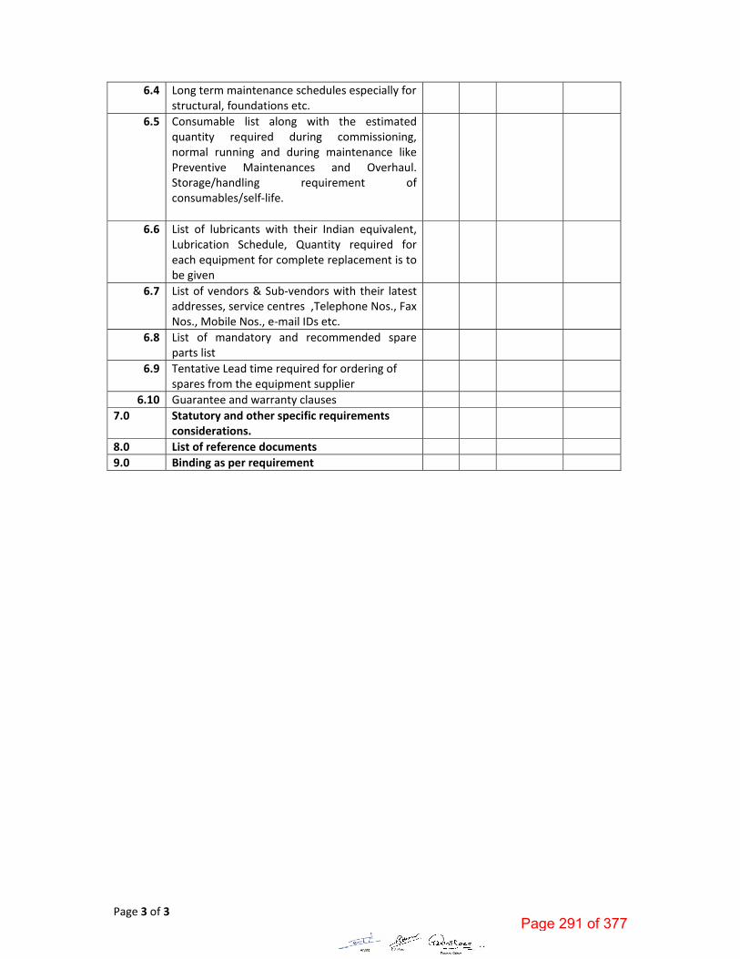
6.4 Long term maintenance schedules especially for structural, foundations etc.
6.5 Consumable list along with the estimated quantity required during commissioning, normal running and during maintenance like Preventive Maintenances and Overhaul. Storage/handling requirement of consumables/self‐life.
6.6 List of lubricants with their Indian equivalent, Lubrication Schedule, Quantity required for each equipment for complete replacement is to be given
6.7 List of vendors & Sub‐vendors with their latest addresses, service centres ,Telephone Nos., Fax Nos., Mobile Nos., e‐mail IDs etc.
6.8 List of mandatory and recommended spare parts list
6.9 Tentative Lead time required for ordering of spares from the equipment supplier
6.10 Guarantee and warranty clauses
7.0 Statutory and other specific requirements considerations.
8.0 List of reference documents
9.0 Binding as per requirement
Page 291 of 377
TECHNICAL SPECIFICATION 4X270 MW BHADRADRI TPS
SPECIFICATION NO.PE-TS-411-554-A001
VOLUME II B
SECTION C
REV. 00 DATE: MARCH 2015
ANNEXURE: VIII
SITE STORAGE AND PRESERVATION
Page 292 of 377
PROJECT ENGINEERING MANAGEMENT, POWER SECTOR
BHARAT HEAVY ELECTRICALS LIMITED-NOIDA
Page 293 of 377

CONTENT
1 SCOPE OF THE DOCUMENT
2 PURPOSE OF STORAGE & PRESERVATION
3 MEASURES TO BE TAKEN FOR STORAGE AND PRESERVATION
a) GENERAL STORAGE REQUIREMENTS
b) GENERAL PRESERVATION REQUIREMENTS
c) GENERAL INSPECTION REQUIREMENTS
4 TYPE OF STORAGE FOR VARIOUS EQUIPMENT
5. CONCLUSION
6. STACKING ARRANGEMENT FOR PLATES AND STRUCTURAL STEEL
Page 294 of 377

1. SCOPE OF THE DOCUMENT
This guideline is prepared in intent to provide proper site storage and preservation of the
Mechanical, Electrical and C & I items / equipment supplied under various bought out
packages/items. This storage procedure shall be followed at different power plant sites by
concerned agency for storage and preservation from the date of equipment received at
site until the same are erected and handed over to the customer.
2. PURPOSE OF STORAGE & PRESERVATION
Many of the items may be required to be kept in stores for long period. It shall therefore
be essential that proper methods of storage and preservation be applied so that items do
not deteriorate, loose some of their properties and become unusable due to atmospheric
conditions and biological elements.
3. MEASURES TO BE TAKEN FOR STORAGE, HANDLING & PRESERVATION
a) GENERAL STORAGE REQUIREMENTS
1. To the extent feasible, materials should be stored near the point of erection. The
storage areas should have adequate unloading and handling facilities with adequate
passage space for movement of material handling equipment such as cranes, fork lift
trucks, etc. The storage of materials shall be properly planned to minimise time loss
during retrieval of items required for erection.
2. The outdoor storage areas as well as semi-closed stores shall be provided with
adequate drainage facilities to prevent water logging. Adequacy of these facilities shall
be checked prior to monsoon.
3. The storage sheds shall be built in conformity with fire safety requirements. The stores
shall be provided with adequate lights and fire extinguishers. ‘No smoking’ signs shall
be placed at strategic locations. Safety precautions shall be strictly enforced.
4. Adequate lighting facility shall be provided in storage areas and storage sheds and
security personnel positioned to ensure enforcement of security measures to prevent
theft and loss of materials.
5. Adequate number of competent stores personnel and security staff shall be deployed
to efficiently store and maintain the equipment / material.
7. The equipment shall be stored in an orderly manner, preserving their identification
slips, tags and instruction booklets, etc., required during erection. The storage of
materials shall be equipment-wise. Loose parts shall be stored in sheds on racks,
Page 1 of 13Page 295 of 377

preserving the identification marks and tags in good condition. The group codes shall
be displayed on the racks
6. At no time shall any materials be stored directly on ground. All materials shall be
stored minimum 200 mm above the ground preferably on wooden sleepers
b) GENERAL PRESERVATION REQUIREMENTS
1. All special measures to prevent corrosion shall be taken like keeping material in dry
condition, avoiding the equipment coming in contact with corrosive fluid like water,
acid etc.
2. Materials which carry protective coating shall not be wrapped in paper, cloth, etc., as
these are liable to absorb and retain moisture. The material shall be inspected and in
case of signs of wear or damages to protective coating, that portion shall be cleaned
with approved solution and coated with an approved protective paint. Complete record
of all such observations and protective measures taken shall be maintained.
3. Generally equipment supplied at site are properly greased or rust protective oil is
applied on machined/ fabricated components. However periodic inspection shall be
carried out to ensure that protection offered is intact.
4. While handling the equipment, no dragging on the ground is permitted. Avoid using
wire rope for lifting coated components. Use polyester slings (if possible) otherwise
protective material (e.g. clothes, wood block etc.) should be used while handling the
components with rope / slings
5. For Equipment supplied with finished paint, touch paint shall be done in case any
surface paint gets peeled off during handling. Otherwise such surfaces shall
necessarily be wrapped with polythene to avoid any corrosion. Further for equipment
wherein finish coat is to be applied at site, site to ensure that equipment is received
with primer coat applied.
6. It shall be ensured by periodic inspection that plastic inserts are intact in tapped holes,
wherever applicable.
7. Pipes shall be blown with air periodically and it shall be ensured that there is no
obstruction.
8. Silica gel or approved equivalent moisture absorbing material in small cotton bags
shall be placed and tied at various points on the equipment, wherever necessary.
9. Heavy rotating parts in assembled conditions shall be periodically rotated to prevent
corrosion/jamming due to prolonged storage.
Page 2 of 13Page 296 of 377

10. All the electrical equipment such as motors, generators, etc. shall be tested for
insulation resistance at least once in three months and a record of such measured
insulation values shall be maintained.
11. Following preservatives/preservation methods can be used depending upon type of
equipment
a. Rust preventive fluid (RPF)
b. Rust protective paints
c. Tarpaulin covers, in case of outdoor storage
d. De-oxy aluminate for weld-ments
c) GENERAL INSPECTION REQUIREMENTS
1. Period inspection of materials with specific reference to –
Ingress of moisture and corrosion damages.
Damage to protective coating.
Open ends in pipes, vessels and equipment -
- In case any open ends are noticed, same shall be capped.
2. Any damages to equipment / materials.
- In case of any damages, these shall be promptly notified and in all cases, the
repairs / rectification shall be carried out.
- Any items found damaged or not suitable as per project requirements shall be
removed from site. If required to store temporarily, they shall be clearly
marked and stored separately to prevent any inadvertent use.
Page 3 of 13Page 297 of 377
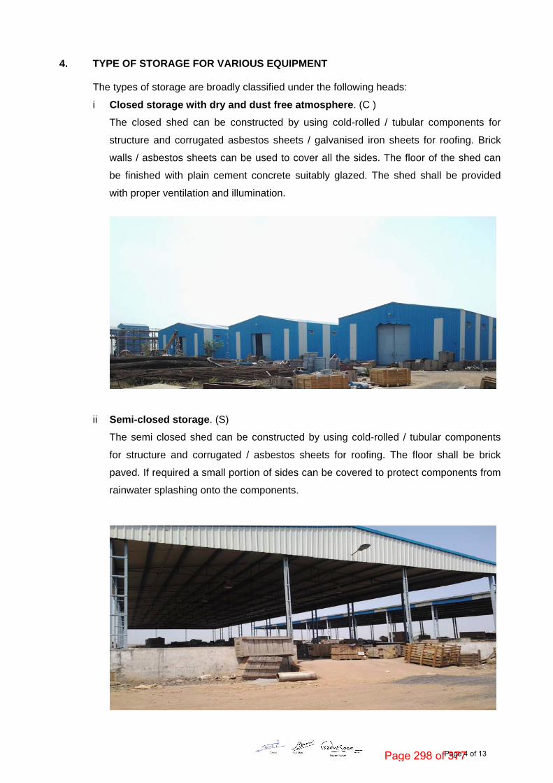
4. TYPE OF STORAGE FOR VARIOUS EQUIPMENT
The types of storage are broadly classified under the following heads:
i Closed storage with dry and dust free atmosphere. (C )
The closed shed can be constructed by using cold-rolled / tubular components for
structure and corrugated asbestos sheets / galvanised iron sheets for roofing. Brick
walls / asbestos sheets can be used to cover all the sides. The floor of the shed can
be finished with plain cement concrete suitably glazed. The shed shall be provided
with proper ventilation and illumination.
ii Semi-closed storage. (S)
The semi closed shed can be constructed by using cold-rolled / tubular components
for structure and corrugated / asbestos sheets for roofing. The floor shall be brick
paved. If required a small portion of sides can be covered to protect components from
rainwater splashing onto the components.
Page 4 of 13Page 298 of 377

iii Open storage (O )
The open yard shall be levelled, well consolidated to achieve raised ground with the
provision of feeder roads for crane approach along with access roads running all
sides. One part of the open yard shall be stone pitched, levelled and consolidated with
raised ground suitable for storing / stacking heavier and critical components with due
space to handle them by cranes etc . Adequate number of sleepers, concrete block
etc. to be provided to make raised platforms to stack critical materials.
A separate yard to be identified as “scrap yard” slightly away from main open yard to
store wooden/steel scraps, which are to be disposed off. This is required to avoid mix
up with regular components as well as to avoid fire hazard.
Some of the components, which are having both machined & un-machined surfaces
and are bulky, shall be stored in open storage area on a raised ground and suitably
covered with water proof / fire retardant tarpaulin.
Page 5 of 13Page 299 of 377

The equipment listed below shall be stored and inspected as per requirement mentioned in the
table below.
Sl. No. Description of the equipment Type of Storage
Check for Remarks
Raw material /mechanical items like pipes, plates, structure sections etc.)
1. Steel pipes ( lined/unlined) S Damage , paint, corrosion, rubber lining peeling
Provide end cap
2. MS Plates S Damage, paint, corrosion
3. SS Plates S Damage
4. Non-metallic pipes S Damage, cracks Provide end cap
5. Stainless steel pipes S Damage , Provide end cap
6. MS sections, beams S Damage, paint, corrosion
7. Cable trays S Damage, condition of preservations
8. Insulation sheets S Damage
9. Insulation C Damage, packing
10. Hangers Rods S Damage, paint, packing
11. Tubes S Damage, paint , packing
Provide end cap
12. Hume pipes O Damage
13. Castings O Damage, paint, corrosion
Fabricated mechanical items (pressure vessels, tanks etc.)
14. Pressure vessels (unlined) O Damage, paint, corrosion,
Covered nozzles
15. Atmospheric storage tanks (unlined)
O Damage, paint, corrosion
Covered nozzles
Page 6 of 13Page 300 of 377

Sl. No. Description of the equipment Type of Storage
Check for Remarks
16. Pressure vessels (lined) S Damage, paint, corrosion, rubber lining
17. Atmospheric storage tanks(lined) S Damage, paint, corrosion, rubber lining
18. Support structures O Damage , paint, corrosion
19. Flanges C Damage , paint, corrosion
20. Fabricated pipes S Damage , paint, corrosion
Provide end cap
21. Vessels internals C Damage , paint, corrosion ,packing
22. Grills S Damage , paint, corrosion
23. Angles S Damage , paint, corrosion
24. Bridge mechanism/clarifier mechanism
O Damage , paint, corrosion
25. Cranes, rails S Damage , paint, corrosion
26. Stair cases O Damage , paint, corrosion
27. Ladders/handrails O Damage , paint, corrosion
28. Fabricated ducts S Damage , paint, corrosion
29. Isolation Gates O Damage , paint, corrosion
30. Fabricated boxes/panels S Damage , paint, corrosion
Mechanical components like valves, fittings, cables glands, spares etc.)
31. Valves S Damage , packing
Page 7 of 13Page 301 of 377

Sl. No. Description of the equipment Type of Storage
Check for Remarks
32. Fittings S Damage , packing Provide end cap
33. Cable glands C Damage , packing
34. Tools & tackles C Damage , packing
35. Nut , bolts, washers, C Damage , packing
36. Gasket & Packings C Damage , packing
37. Copper tubes C Damage , packing, corrosion
Provide end cap
38. SS tubing C Damage , packing Provide end cap
Rotating assemblies (pumps, blowers, stirrers, fans, compressors etc.)
39. Pumps S Damage , packing, corrosion
Shaft rotation
40. Blowers/Compressors S Damage , packing, corrosion
Shaft rotation
41. Agitators/stirrers/radial launders C Damage , packing, corrosion
Shaft rotation
42. Rollers for chlorine tonner mounting
C Damage , packing, corrosion
43. Centrifuge S Damage , packing,
44. Gear box C Damage , packing, corrosion
45. Bearings C Damage , packing, corrosion
46. Fans S Damage , packing, corrosion
47. Dosing skids S Damage , packing, corrosion
48. Pump assemblies S Damage , packing, corrosion
49. Air washers( INTERNALS) S Damage , packing
50. Air conditioners ( split) C Damage , packing
Page 8 of 13Page 302 of 377

Sl. No. Description of the equipment Type of Storage
Check for Remarks
51. Elevators( CONTAINERIZED) O Damage , packing, corrosion
52. Chillers/VA machines S Damage , packing
53. Air handling Unit/Package unit S Damage , packing
54. Chlorinators & Evaporators C Damage , packing
55. Ejectors C Damage , packing
56. Electrolyser C Damage , packing
Miscellaneous items like chain pulley blocks, hoists etc.
57. Chain pulley blocks S Damage, Packing
58. Electric hoists S Damage, Packing
59. Fire extinguishers C Damage, expiry date
60. Fork Lift Truck S Damage, Packing
61. Hydraulic Mobile Crane O Damage, Packing
62. Mobile Pick Up & Carry Crane O Damage, Packing
63. Motor boats O Damage, Packing
64. Safety showers S Damage, Packing
65. Diffusers/dampers S Damage, Packing
Chemicals and consumables ( acid, alkali, paints, oils, reagents and special chemicals)
66. Hydro Chloric Acid (HCl)
Store in canes/ storage tank in dyke area
Date of production/ leakage/fumes
hazardous chemical
67. Sulphuric acid (H2SO4 )
Store in canes/ storage tank in dyke area
Date of production/ leakage/fumes
hazardous chemical
Page 9 of 13Page 303 of 377

Sl. No. Description of the equipment
Type of Storage
Check for Remarks
68. Sodium hydroxide (NaOH)
Store in canes/ storage tank in dyke area
Date of production/ leakage/ fumes/ breather
hazardous chemical ,breather to be checked for air ingress
69. Sodium hypo chlorite To be stored under shed
Date of production/ leakage/ fumes
hazardous chemical ,self-life normally 15-30 days after which strength of chemical decays
70. Ammonia S Date of production/ leakage/ fumes
Store in closed storage tanks, hazardous chemical
71. CW treatment chemicals S Date of production , Self-life
Store in closed canes
72. RO/UF cleaning chemicals S Date of production , Self-life
Store in closed canes
73. Lime C Damage to packing , seepage
Prevent moisture, rain
74. Alum bricks C Damage to packing Prevent moisture, rain
75. Poly electrolyte S Store in closed storage tanks
76. Laboratory chemicals( powder)
C Damage, Packing self-life
77. Laboratory chemicals( liquid)
C Damage, Packing self-life
78. Lubrication oils C Leakage
79. Paints S Leakage ,air tightness
80. Sand O Damage of packing No hooks
81. Salt (NaCl) C Damage of packing, water ingress
Prevent moisture, rain
82. Anthracite S Damage of packing
83. Activated carbon S Damage of packing
Page 10 of 13Page 304 of 377
Sl. No. Description of the equipment
Type of Storage
Check for Remarks
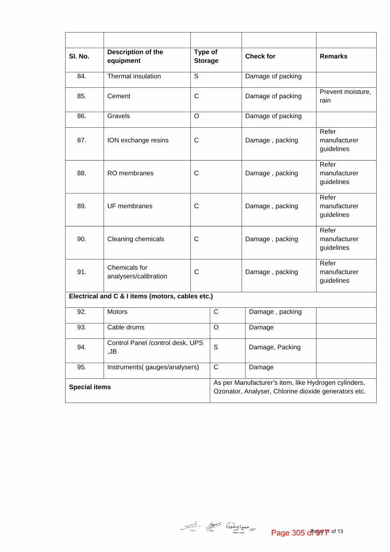
84. Thermal insulation S Damage of packing
85. Cement C Damage of packing Prevent moisture, rain
86. Gravels O Damage of packing
87. ION exchange resins C Damage , packing Refer manufacturer guidelines
88. RO membranes C Damage , packing Refer manufacturer guidelines
89. UF membranes C Damage , packing Refer manufacturer guidelines
90. Cleaning chemicals C Damage , packing Refer manufacturer guidelines
91. Chemicals for analysers/calibration
C Damage , packing Refer manufacturer guidelines
Electrical and C & I items (motors, cables etc.)
92. Motors C Damage , packing
93. Cable drums O Damage
94. Control Panel /control desk, UPS ,JB
S Damage, Packing
95. Instruments( gauges/analysers) C Damage
Special items As per Manufacturer’s item, like Hydrogen cylinders, Ozonator, Analyser, Chlorine dioxide generators etc.
Page 11 of 13Page 305 of 377

5. CONCLUSION
Concerned storage agency at site should make sure that loss in equipment performance
and wear & tear are minimised through proper storage and preservation. The above are
broad guidelines and cover major equipment / materials. However specific storage
practices shall be followed as per manufacturer recommendation. All the necessary
measures even in addition to the ones mentioned above, if found necessary, should be
taken to achieve the objective.
Page 12 of 13Page 306 of 377

Figure – 1 – PLATE STACKING ARRANGEMENT
Figure – 2 – STRUCTURAL STEEL STACKING ARRANGEMENT
Page 13 of 13Page 307 of 377

TECHNICAL SPECIFICATION 4X270 MW BHADRADRI TPS STANDARD SPECIFICATION
SPECIFICATION NO.PE-TS-411-554-A001
VOLUME II B
SECTION D
REV. 00 DATE: MARCH 2015
SECTION: D
STANDARD SPECIFICATION
Page 308 of 377

TECHNICAL SPECIFICATION
AIR WASHER
SPECIFICATION NO.PES-554-01
VOLUME II B
SECTION D
REV. 00 DATE: NOV 2012
SHEET 1 OF 3
SECTION-D
AIR WASHER
Page 309 of 377
TECHNICAL SPECIFICATION
AIR WASHER
SPECIFICATION NO.PES-554-01
VOLUME II B
SECTION D
REV. 00 DATE: NOV 2012
SHEET 2 OF 3
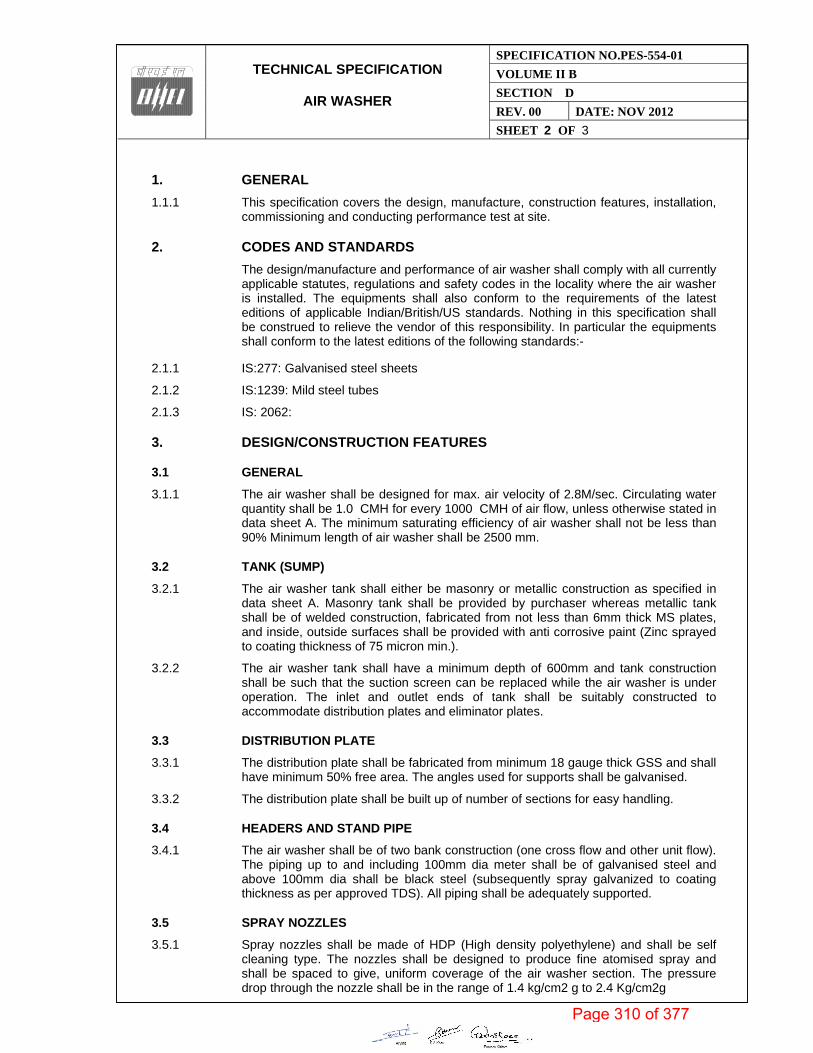
1. GENERAL
1.1.1 This specification covers the design, manufacture, construction features, installation, commissioning and conducting performance test at site.
2. CODES AND STANDARDS
The design/manufacture and performance of air washer shall comply with all currently applicable statutes, regulations and safety codes in the locality where the air washer is installed. The equipments shall also conform to the requirements of the latest editions of applicable Indian/British/US standards. Nothing in this specification shall be construed to relieve the vendor of this responsibility. In particular the equipments shall conform to the latest editions of the following standards:-
2.1.1 IS:277: Galvanised steel sheets
2.1.2 IS:1239: Mild steel tubes
2.1.3 IS: 2062:
3. DESIGN/CONSTRUCTION FEATURES
3.1 GENERAL
3.1.1 The air washer shall be designed for max. air velocity of 2.8M/sec. Circulating water quantity shall be 1.0 CMH for every 1000 CMH of air flow, unless otherwise stated in data sheet A. The minimum saturating efficiency of air washer shall not be less than 90% Minimum length of air washer shall be 2500 mm.
3.2 TANK (SUMP)
3.2.1 The air washer tank shall either be masonry or metallic construction as specified in data sheet A. Masonry tank shall be provided by purchaser whereas metallic tank shall be of welded construction, fabricated from not less than 6mm thick MS plates, and inside, outside surfaces shall be provided with anti corrosive paint (Zinc sprayed to coating thickness of 75 micron min.).
3.2.2 The air washer tank shall have a minimum depth of 600mm and tank construction shall be such that the suction screen can be replaced while the air washer is under operation. The inlet and outlet ends of tank shall be suitably constructed to accommodate distribution plates and eliminator plates.
3.3 DISTRIBUTION PLATE
3.3.1 The distribution plate shall be fabricated from minimum 18 gauge thick GSS and shall have minimum 50% free area. The angles used for supports shall be galvanised.
3.3.2 The distribution plate shall be built up of number of sections for easy handling.
3.4 HEADERS AND STAND PIPE
3.4.1 The air washer shall be of two bank construction (one cross flow and other unit flow). The piping up to and including 100mm dia meter shall be of galvanised steel and above 100mm dia shall be black steel (subsequently spray galvanized to coating thickness as per approved TDS). All piping shall be adequately supported.
3.5 SPRAY NOZZLES
3.5.1 Spray nozzles shall be made of HDP (High density polyethylene) and shall be self cleaning type. The nozzles shall be designed to produce fine atomised spray and shall be spaced to give, uniform coverage of the air washer section. The pressure drop through the nozzle shall be in the range of 1.4 kg/cm2 g to 2.4 Kg/cm2g
Page 310 of 377

TECHNICAL SPECIFICATION
AIR WASHER
SPECIFICATION NO.PES-554-01
VOLUME II B
SECTION D
REV. 00 DATE: NOV 2012
SHEET 3 OF 3
3.6 ELIMINATOR PLATE
3.6.1 Eliminator plate shall be fabricated from 22 gauge thick GSS (Zinc coating thickness as per approved TDS).The eliminator section shall have minimum 6 bends. Spacer bars, tie rods and supports shall be of galvanised steel construction. Eliminator box shall be complete with suitable drop tray and drain pipe.
3.7 SUCTION SCREENS
3.7.1 Suitable no. of suction screens shall be provided by vendor and one set of spare screens shall be furnished along with each air washer.
3.8 INSPECTION DOOR AND MARINE LIGHT
3.8.1 Air tight inspection door of 600x700mm, metallic construction shall be provided. The air washer shall be equipped with marine light as required.
3.9 MAKE UP, DRAIN AND QUICK FILL CONNECTION
3.9.1 The air washer shall be provided with quick fill and make up connection. The quick fill valve shall be a globe valve. Float valve for making connection shall be backed up by a gate valve. Drain connections complete with isolating valves shall be provided for both suction and main tank. Over-flow pipe shall be provided for main tank and shall be connected to drain pipe, before the isolating valve or drain. In case of masonry tanks suitable pipe pieces with stiffener plates shall be provided by Vendor for use during casting of masonry tank.
4. DATA TO BE FURNISHED BY VENDOR AFTER AWARD OF CONTRACT
4.1.1 Performance curve for air washer
4.1.2 GA drg.
4.1.3 Foundation drag. weight, dynamic loading etc.
4.1.4 O&M manual
Page 311 of 377
TITLE SPECIFICATION NO. PE-TS-411-554-A001
AIR WASHER VOLUME II-B
DATA SHEET - A SECTION D
REV 00 DATE : MARCH 2015
SHEET 1 OF 2
PE
M-6
666-
0
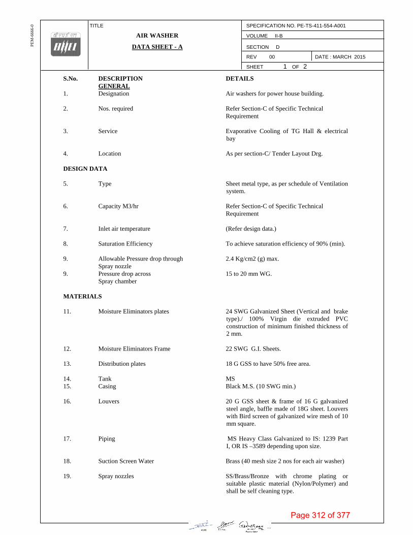
S.No. DESCRIPTION DETAILS GENERAL 1. Designation Air washers for power house building. 2. Nos. required Refer Section-C of Specific Technical Requirement 3. Service Evaporative Cooling of TG Hall & electrical
bay 4. Location As per section-C/ Tender Layout Drg. DESIGN DATA 5. Type Sheet metal type, as per schedule of Ventilation
system. 6. Capacity M3/hr Refer Section-C of Specific Technical Requirement 7. Inlet air temperature (Refer design data.) 8. Saturation Efficiency To achieve saturation efficiency of 90% (min). 9. Allowable Pressure drop through 2.4 Kg/cm2 (g) max. Spray nozzle 9. Pressure drop across 15 to 20 mm WG. Spray chamber MATERIALS 11. Moisture Eliminators plates 24 SWG Galvanized Sheet (Vertical and brake
type)./ 100% Virgin die extruded PVC construction of minimum finished thickness of 2 mm.
12. Moisture Eliminators Frame 22 SWG G.I. Sheets. 13. Distribution plates 18 G GSS to have 50% free area. 14. Tank MS 15. Casing Black M.S. (10 SWG min.) 16. Louvers 20 G GSS sheet & frame of 16 G galvanized
steel angle, baffle made of 18G sheet. Louvers with Bird screen of galvanized wire mesh of 10 mm square.
17. Piping MS Heavy Class Galvanized to IS: 1239 Part
I, OR IS –3589 depending upon size. 18. Suction Screen Water Brass (40 mesh size 2 nos for each air washer) 19. Spray nozzles SS/Brass/Bronze with chrome plating or
suitable plastic material (Nylon/Polymer) and shall be self cleaning type.
Page 312 of 377

TITLE SPECIFICATION NO. PE-TS-411-554-A001
AIR WASHER VOLUME II-B
DATA SHEET - A SECTION D
REV 00 DATE : MARCH 2015
SHEET 2 OF 2
PE
M-6
666-
0
20. Flooding Nozzles SS/Nylon/Polymer. 21. Banks Two spray banks each connected to individual
header EQUIPMENT SELECTION CRITERIA 22. Face Velocity through louver. Not to exceed 2.5 m/s 23. Max. Pressure drop Not to exceed 6.5 mm Wg when clean 24. Saturation efficiency Not less than 90%. 25. Face velocity of air Not to exceed 2.5 m/s. & 2.25 M/s (Max.) through spray chamber. & fill section 26. Allowable pressure drop 15 to 20 mm Wg. for washing chamber. NOTE:
1) All parts coming in contact with moisture for air washer shall be spray galvanized/epoxy painted (2 coat of rust preventing epoxy primer & 2 coat of finished paint from both sides.) 2) Moisture eliminator shall have bends at 30 Degree with the direction of air flow & shall have effectively hooked edges for traping the water.
Page 313 of 377

TECHNICAL SPECIFICATION
LOW PRESSURE AIR DISTRIBUTION
SYSTEM
SPECIFICATION NO.PES-554-02
VOLUME II B
SECTION D
REV. 02 DATE: NOV 2012
SHEET 1 OF 7
SECTION-D
LOW PRESSURE AIR DISTRIBUTION SYSTEM
Page 314 of 377
TECHNICAL SPECIFICATION
LOW PRESSURE AIR DISTRIBUTION
SYSTEM
SPECIFICATION NO.PES-554-02
VOLUME II B
SECTION D
REV. 02 DATE: NOV 2012
SHEET 2 OF 7
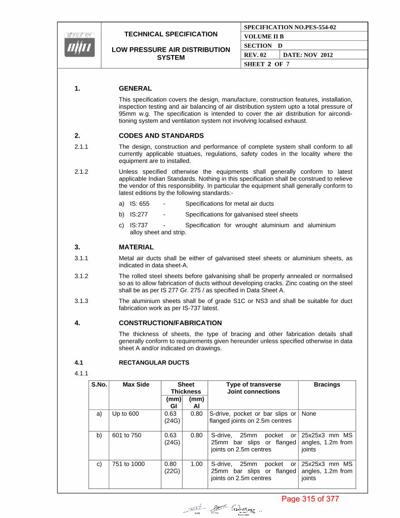
1. GENERAL
This specification covers the design, manufacture, construction features, installation, inspection testing and air balancing of air distribution system upto a total pressure of 95mm w.g. The specification is intended to cover the air distribution for aircondi-tioning system and ventilation system not involving localised exhaust.
2. CODES AND STANDARDS
2.1.1 The design, construction and performance of complete system shall conform to all currently applicable stuatues, regulations, safety codes in the locality where the equipment are to installed.
2.1.2 Unless specified otherwise the equipments shall generally conform to latest applicable Indian Standards. Nothing in this specification shall be construed to relieve the vendor of this responsibility. In particular the equipment shall generally conform to latest editions by the following standards:-
a) IS: 655 - Specifications for metal air ducts
b) IS:277 - Specifications for galvanised steel sheets
c) IS:737 - Specification for wrought aluminium and aluminium alloy sheet and strip.
3. MATERIAL
3.1.1 Metal air ducts shall be either of galvanised steel sheets or aluminium sheets, as indicated in data sheet-A.
3.1.2 The rolled steel sheets before galvanising shall be properly annealed or normalised so as to allow fabrication of ducts without developing cracks. Zinc coating on the steel shall be as per IS 277 Gr. 275 / as specified in Data Sheet A.
3.1.3 The aluminium sheets shall be of grade S1C or NS3 and shall be suitable for duct fabrication work as per IS-737 latest.
4. CONSTRUCTION/FABRICATION
The thickness of sheets, the type of bracing and other fabrication details shall generally conform to requirements given hereunder unless specified otherwise in data sheet A and/or indicated on drawings.
4.1 RECTANGULAR DUCTS
4.1.1
S.No. Max Side Sheet Thickness
Type of transverse Joint connections
Bracings
(mm)GI
(mm) Al
a) Up to 600 0.63 (24G)
0.80 S-drive, pocket or bar slips or flanged joints on 2.5m centres
None
b) 601 to 750 0.63 (24G)
0.80 S-drive, 25mm pocket or 25mm bar slips or flanged joints on 2.5m centres
25x25x3 mm MS angles, 1.2m from joints
c) 751 to 1000 0.80 (22G)
1.00 S-drive, 25mm pocket or 25mm bar slips or flanged joints on 2.5m centres
25x25x3 mm MS angles, 1.2m from joints
Page 315 of 377

TECHNICAL SPECIFICATION
LOW PRESSURE AIR DISTRIBUTION
SYSTEM
SPECIFICATION NO.PES-554-02
VOLUME II B
SECTION D
REV. 02 DATE: NOV 2012
SHEET 3 OF 7
d) 1001 to1500 0.80 (22G)
1.00 40x40x3mm MS angle, flanged connections or 40mm pocket or40mm bar slips with 35x3mm bar reinforcing on 2.5m centres
40x40x3 mm MS angles, 1.2m from joints
e) 1501 to2250 1.00 (20G)
1.50 40x40x3mm MS angle, flanged connections or 40mm pocket or40mm bar slips, 1M maximum centres, with 35x3mm bar reinforcing
40x40x3 mm diagonal angles or 40x40x3mm angles, 600mm from joints
f) 2251 & above 1.25 (18G)
1.80 50x50x3mm MS angles,connections or 40mm pocket or 40 mm bar slips, 1M maximum centres with 35x3mm bar reinforcing.
50x50x3mm diagonal angles or 50x50x3mm angles 600 mm from joints.
g) No bracing is required if transverse joints are less than 600mm apart
h) For ducts larger than 2250mm, special handling and supporting methods shall be provided as per the approval of Purchaser
4.1.2 All rectangular ducts having either dimension larger than 450mm shall be cross broken except these ducts which are insulated with sand cement plaster. Air outlet connections on ducts need not be cross broken.
4.1.3 The seams on duct cones shall be of Pittsburgh type. Longitudinal seams shall be smooth inside the ducts.
4.1.4 The flanges used for transverse joints shall be joined together with GI bolts (grade 4.6) and nuts spaced at 125mm centres as per following:
a) Upto 1000mm - 6 mm dia GI bolts b) 1001 to 1500 - 8 mm dia GI bolts c) 1501 and above - 10mm dia GI bolts
4.1.5 The MS angle flanges shall be connected to ducts with rivets at approx. 100mm centres. The flanged joints shall have 6mm thick felt packing stuck to flanges with shellac varnish. The holes in the felt packing shall be burnt through. The ducts are to be tapped 6mm across the MS flanges.
4.1.6 MS angles used for bracings shall be tack welded to the ducts or rivetted at 125mm centres, as applicable.
4.2 ROUND DUCTS
4.2.1
S.No. Duct dia-mm Sheet Thickness
Reinforcing
(mm)GI
(mm) Al
a) Up to 150 0.63 (24G)
0.80 None
b) 151 to 600 0.80 (22G)
1.00 None
c) 601 to 1000 1.00 (20G)
1.50 40x40x3mm girth MS
d) 1001 to1250 1.00 1.50 40x40x3mm girth MS angles at 2.0 meter centres
Page 316 of 377

TECHNICAL SPECIFICATION
LOW PRESSURE AIR DISTRIBUTION
SYSTEM
SPECIFICATION NO.PES-554-02
VOLUME II B
SECTION D
REV. 02 DATE: NOV 2012
SHEET 4 OF 7
(20G) e) 1251 & above 1.25
(18G)1.80 40x40x3mm girth MS angles at 1.2m centres
4.2.2 The seams on round ducts may be continuously welded or grooved longitudinal seam. In case of welding of GI sheet, zinc rich paint shall be applied on the welded zone.
4.2.3 Round ducts shall either be joined by welding or the ducts shall be swedged 40mm from the ends such that larger end will butt against the swedge and is held in place with sheet metal screws.
4.3 DUCT SUPPORTS
Unless specified otherwise on drawings, rectangular ducts with larger side of 2250mm or above shall be supported by 15mm MS rods and 50x50x3mm and MS angles while those below 2250 mm shall be supported by 10mm MS rods and all angles shall be given a coat of primer paint. The duct supports shall be at a distance not exceeding 1800mm. The MS rods shall be fixed to MS angle cleats, which in turn are fixed to ceiling slab by suitable anchor fasteners. All anchor fasteners, MS angle cleats, coach screws, hooks and other supporting material required shall be provided by vendor.
However, If ducts are thermally insulated, the MS angles and supports shall not be in direct contact with ducts, for which purpose wooden pieces/ Resin bonded fibre glass sheets (50 mm thick) shall be used in between.
4.4 FLEXIBLE CONNECTIONS
Wherever the sheet metal ducts connects to intake or discharge of fan units a flexible connection of at least 150mm width made by closely woven double layer Fire resistant or canvas shall be provided. The same shall be attached to angle iron frames on equipment and to similar frame on duct or casing by means of a steel band or collar fitting over the end of the flexible connection and bolted through angle iron frame so as to clamp securely between the band and the angle frame.
4.5 TRANSFORMATIONS AND BREACHES
All curves, bends, offsets and other transformations shall be made for easy and noiseless flow of air. The throat of every branch duct shall be sized to have a velocity not exceeding that in the main duct to which the branch is connected.
4.6 CAULKING
Wherever duct passes through wall, the opening between masonary and duct work shall be neatly caulked or sealed to prevent movement of air from one space to adjoin by space with a rated fire resistant material.
4.7 EASEMENT
Normally pipe hangers, light fitting rods etc. shall not be allowed to pass through the ducts. Wherever, It becomes absolutely essential to pass these hangers/rods etc. Through the ducts, prior approval of purchaser shall be taken and light streamlines easement around the same shall be provided to maintain smooth air flow.
4.8 ACCESS DOORS
Access doors shall be provided in ducts, plenums etc. on both sides to allow access and servicing of equipment viz. pipes, dampers, coils, valves, heaters etc.
All access doors shall be adequately sized and lined suitably with felt to prevent air leakage. The doors shall be of built-up construction, structurally strong and shall have
Page 317 of 377

TECHNICAL SPECIFICATION
LOW PRESSURE AIR DISTRIBUTION
SYSTEM
SPECIFICATION NO.PES-554-02
VOLUME II B
SECTION D
REV. 02 DATE: NOV 2012
SHEET 5 OF 7
at least two hinges each, and shall be with two rust proof window sash locks of approved type. All doors shall be so set as to flush with outer finish of duct insulation etc.
4.9 DAMPERS AND SPLITTERS
4.9.1 Dampers and splitters shall be provided at suitable points for proportional volume control of the system. Splitters and dampers shall be made of minimum 18 gauge GSS of quadrant type with locking device mounted outside the duct at accessible location.
4.9.2 Fire Dampers
Fire dampers/fire doors shall be provided as specified in Data Sheet -A and shall be installed at locations indicated on drawings and/or as required/approved by purchaser, including all openings in passage of duct work through fire walls and floors etc. The fire damper shall be of electrical type with damper motor actuated by thermal sensor or fusible link type.
4.9.3 Gravity operated back draft dampers shall be provided to ensure pressurisation of rooms as specified. These dampers shall be designed such as not to allow infiltration of outside air while forced exit of air shall be achieved through this damper. The louvres shall be freely mounted on spindles to allow the dampers to open with the pressure developed by the fan. The dampers shall be provided with flange at inlet.
4.9.4 Vanes
Unless otherwise shown in the drawings all elbows shall be such that the throat radius is 75% of the duct width. In case throat radius is smaller, suitable single thickness vanes of approved details shall be provided.
4.9.5 Flashing
For the ducts penetrating roofs or outside walls, provision of flashing shall be made by the ducting vendor.
4.10 DIFFUSERS AND GRILLS
The type and quantity of diffusers and grills is indicated on enclosed drawings/data sheet A. The size/quantity of diffusers/ grills indicated in the drawing/data sheet is indicative and is for vendor’s reference purpose only. Vendor shall ensure that the diffusers/grills offered are of requisite capacity, throw and terminal velocity. The pressure drop and noise levels shall be as per data sheet. A enclosed. The diffusers/grills shall be approved by purchaser.
Unless specified otherwise the diffusers/grills shall be of mild steel land painted with two coats of primer paint. Supply air grills shall be complete with volume control dampers. Supply air grills shall be double deflection type while Return Air grills can be single deflection type. Ceiling outlets/diffusers shall have volume control dampers, fixed grids and blanking baffles. All volume control dampers shall be operated by a key from the front of grills/diffusers.
Suitable vanes shall be provided in duct collars to have uniform air distribution. Blank-off baffles wherever required, shall also be provided.
4.11 PLENUMS AND RA BOXING
All plenum chambers and/or connections to fans, dampers etc. shall be constructed in 18 gauge GI sheet. supported on 40x40x6mm MS angle frames. All vertical angles shall be riveted at appox. 125mm. centres to the casing. Suitable caulking compound (Pecora or equivalent) shall be inserted between the base of the angle and all masonary construction to which angles are fastened.
Page 318 of 377
TECHNICAL SPECIFICATION
LOW PRESSURE AIR DISTRIBUTION
SYSTEM
SPECIFICATION NO.PES-554-02
VOLUME II B
SECTION D
REV. 02 DATE: NOV 2012
SHEET 6 OF 7
Return air boxing requirements if any are indicated in data sheet-A and the same shall be provided by vendor. The return air box shall be fabricated out of GI sheets shall be insulated with 25mm thick fibre-glass.
4.12 ACCOUSTIC LINING
The ducts shall be lined acoustically from inside as given in data- sheet A and/or section C of the specification.
4.13 PAINTING
Wherever specified the ducts shall be painted or lined with suitable anti-corrosive paint/ lining as per approval of purchaser. In particular the ducts coming in contact with acid fumes shall be epoxy coated, inside and outside.
4.14 THERMAL INSULATION
Thermal insulation shall be as per data sheet - A and the insulation shall conform to enclosed spec. no. PES-553-08.
5. INSPECTION AND TESTING
5.1 INSPECTION & TESTING DURING FABRICATION–BY MAIN VENDOR
5.1.1 Visual inspection of GI sheets and angles, channels etc. – dents, black spots, chipping of zinc coating, white dust on galvanised sheets shall be avoided. Pitting , lamination in angles and channels shall be avoided.- visual inspection by Main Vendor.
5.1.2 Galvanised sheets - Test certificate shall be furnished for visual check, coating thickness, adhesion test, sheet thickness, uniformity of coating –review of TC by BHEL/Customer
5.1.3 Check for dimensions & mass as per latest IS-277.
5.1.4 Check for defect, twists, ungalvanised spots as per IS-2629.
5.1.5 Bend test & wrapping test as per IS-277.
5.1.6 Zinc coating test on samples as per IS-6745.
5.2 INSPECTION & TESTING AT SITE.
5.2.1 The duct branches, elbows etc. shall be inspected and the joints and connections etc, are to be checked before they are assembled in position.
5.2.2 After completion, all duct systems shall be checked and tested for air leakage, tightness, velocity, pressure drop, vibration and noise etc.
6. BALANCING
6.1.1 The entire air distribution system shall be balanced by vendor to supply the air quantities as required in various rooms so as to maintain the requisite temperature and air flow in the conditioned spaces. The final balance of air quantities through each grill/diffuser etc. shall be recorded and submitted to purchaser for approval. Proper steps shall be taken to have a uniform temperature in all enclosures, with utmost care for noise level to be within tolerance limit
6.1.2 All instruments required for testing/balancing etc. of the air distribution system shall be provided by vendor.
Page 319 of 377

TECHNICAL SPECIFICATION
LOW PRESSURE AIR DISTRIBUTION
SYSTEM
SPECIFICATION NO.PES-554-02
VOLUME II B
SECTION D
REV. 02 DATE: NOV 2012
SHEET 7 OF 7
7. DATA TO BE FURNISHED BY VENDOR AFTER THE AWARD OF CONTRACT
7.1 Fabrication drawings of ducts and grilles, louvers, dampers, etc, including typical details of grilles dampers etc.
7.2 Test certificates in line with scope of inspection.
7.3 Other dimensional drawings & documents as may be required by purchaser for better understanding of the system & for preparation of operation, maintenance & instruction manual.
Page 320 of 377

TITLE SPECIFICATION NO. PE-TS-411-554-A001
LOW PRESSURE VOLUME II-B
AIR DISTRIBUTION SYSTEM SECTION D
DATA SHEET - A REV 00 DATE: MARCH 2015
SHEET 1 OF 1
PE
M-6
666-
0
1) General (List of areas) As per schedule/tender drgs of Ventilation system.
2) i) GSS Duct Work a) Type Zinc coating (Refer Section-C of Specific Technical Requirement) b) 1.25 mm thk ducting Bidder to estimate as per Drawings/sketch c) 1.0 mm thk ducting Separately for Ventilation system. d) Any other size (area wise) e) Battery Room ducting. MS with epoxy painting on both sides. 3) Special painting MS Ducts in Battery Room to be epoxy
painted. Both interior & exterior) 4) Thermal Insulation Required in duct for vent. System
exposed to Sun only (furnished by Cement sand plaster) 5) SA grilles (for each size) (SQ.M) To suit airflow as per schedule/tender drgs. 6) Exhaust Gravity/Manual relief dampers (for each -do- size & to maintain a slight positive pressure inside.)
a) Frame 1.6mm M.S. b) Louver 0.8mm Al.
NOTE: 1) Ducting shall be as per IS-655 standard. 2) Opposed blade type volume control damper (gang operated) shall be provided at each supply air grilles. 3) Bidder to provide suitable gasketing at each duct flange.(Asbestos shall not be used). 4) Supply Air Grills shall have 2 (two) set of adjustable louvres. 5) Bidder to indicate unit rates for variable items like ducting, grilles with & without volume control
damper, gravity damper, thermal insulation, etc. 6) Grilles, frames & louvres shall be of at least 18 SWG sheet and 20 SWG MS respectively. 6) Fire damper shall be solenoid operated in accordance with NFPA. The solenoid shall be charged during
open condition and shall be de-energising to close. 7) Access door in ducting system shall be provided as required. 8) MS Angle (painted) shall be used only as duct supports. 9) Velocity thru duct shall not exceed 12 M/sec for Ventilation system. 10) All exhaust/return air grilles shall have one set of louvres in the front or thick rat-proof wire net guards.
Page 321 of 377

TECHNICAL SPECIFICATION
VENTILATION FANS
SPECIFICATION NO.PES-554-03
VOLUME II B
SECTION D
REV. 02 DATE: NOV 2012
SHEET 1 OF 4
SECTION-D
VENTILATION FANS
Page 322 of 377

TECHNICAL SPECIFICATION
VENTILATION FANS
SPECIFICATION NO.PES-554-03
VOLUME II B
SECTION D
REV. 02 DATE: NOV 2012
SHEET 2 OF 4
1. GENERAL
This specification covers the design, manufacture, testing of performance at manufacturer’s/sub-contractors works, delivery at site, handling at site, erection and commissioning of ventilation fans.
2. CODE AND STANDARDS
The design, manufacture and performance of equipment shall comply with all currently applicable statutes, regulations and safety codes in the locality where it is to be installed. The equipment shall conform to latest edition of applicable Indian Stand-ards or their equivalent standards. Nothing in this specification shall be construed to relieve the vendor of this responsibility. In particular the equipment shall conform to the latest editions of the Following standards.
2.1.1 IS:4894 -Centrifugal fans
2.1.2 IS:3588 -Electric Axial Flow fans
2.1.3 IS:2312 -Propeller type A.C. ventilation fans
2.1.4 IS-3963 -Roof extractor units
2.1.5 BS:848 -Method of performance test for fans.
2.1.6 AMCA publication 99 standards handbook
2.1.7 AMCA standard 210, Test code for air moving devices.
3. DESIGN AND CONSTRUCTION
3.1 THE ENCLOSED DATA SHEET A GIVES THE NECESSARY DETAILS FOR CENTRIFUGAL/AXIAL/ROOF EXTRACTOR UNITS ETC.
3.2 WELDING PROCESS AND WELDERS EMPLOYED FOR FABRICATION SHALL BE QUALIFIED AS PER ASME SEC. IX
3.3 CASING
3.3.1 The centrifugal fans casing shall be of welded construction fabricated with heavy gauge material (min 3 mm) with flanges (min. 5 mm) on inlet and out let side for direct connection and shall be rigidly reinforced and supported by structural angles. The seams shall be permanently sealed airtight. Horizontal Split casings shall be provided on large size fans. Casing drain (at bottom) with threaded plug/ with valve shall be provided, as required. All mounting/ connecting holes shall be drilled off centre.
3.3.2 The axial flow casing for supply fans/roof extractors shall be of heavy gauge construction (min 3 mm) properly reinforced for rigidity and shall be complete with suitable supports. Access doors with suitable locking arrangement shall be provided in the casing for easy access to the motor and impeller. External junction box/ Terminal box on casing with IP-55 protection shall be provided, if required. Wiring for motor from external junction box/ Terminal box shall be through flexible conduit.
3.3.3 Suitable motor brackets designed for rigid mounting of motors, shall be provided for roof extractors and wall mounted exhaust/ supply fans.
3.4 IMPELLER
3.4.1 Centrifugal fan impeller shall have die formed, aerofoil or laminar blades welded to the rim and back plate and shall have non-overloading, self cleaning characteristics. Rim shall be spun to have smooth contour. If required, intermediate stiffening rings
Page 323 of 377

TECHNICAL SPECIFICATION
VENTILATION FANS
SPECIFICATION NO.PES-554-03
VOLUME II B
SECTION D
REV. 02 DATE: NOV 2012
SHEET 3 OF 4
shall be provided. Shaft sleeves shall be furnished, if specified. The impeller, pulley and shaft sleeve shall be secured to the shaft by key and/or nuts (threaded opposite to direction of rotation of impeller). The impeller shall be statically and dynamically balanced.
3.4.2 The axial fan impeller shall be of high efficiency aerofoil design. The blades shall be mounted on a streamlined hub and the impeller shall be mounted directly on the motor shaft. Impeller shall be in one piece however; fabricated blades will be acceptable up to 450 mm impeller diameter.
3.4.3 Roof ventilator impeller may either be centrifugal or axial type. Backward inclined blades shall be provided for centrifugal impellers. Blades may be die-formed or cast. Axial flow impeller shall be directly mounted to motor shaft whereas centrifugal impeller may either be direct-driven or belt-driven. The shaft of belt-driven centrifugal fan shall be solid cold rolled carbon steel, ground and polished. However, direct mounted impellers are preferred.
3.5 BEARINGS:
3.5.1 The centrifugal fan bearing may be ball, roller or sleeve bearings of self-aligning heavy duty type with adequate capacity and life. Make of Bearings to be specified. Bearings shall be oil/grease lubricated and provided with fittings for lubrication from outside and shall be located in easily accessible position to facilitate maintenance.
3.6 INLET CONES AND GUARDS
3.6.1 Centrifugal fans inlet shall be spun to have a smooth contour. Inlet screen, if provided, shall be galvanised wire mesh of 25 mm square with wire thickness of min. 1.5 mm.
3.6.2 Inlet cone, outlet bell and suitably designed guards shall be provided.
3.7 GUIDE VANES:
3.7.1 In case of vane axial fans guide vanes shall be provided on discharge side.
3.8 BASE PLATE AND VIBRATION ISOLATORS
3.8.1 Base plate and vibration isolators, which may be double deflection rubber in shear or rubber in compression type or spring type shall be provided. With each fan rubber bushes, washers wherever needed for vibration isolator in sufficient nos. shall be included, as required, to ensure isolation of foundation from vibration of equipment. For roof ventilators suitable mounting arrangement shall be provided such that there is no ingress of rain water into the building.
3.9 HOOD AND COWL
3.9.1 Roof exhaustors shall be provided with hinge type hood providing easy access to motor and impeller. Weather proof lockable type disconnect switch shall be provided such that hood can open only when the disconnect switch is in’off’ position. On larger size of roof ventilators hoods may be of split construction. 15 mm mesh galvanised bird screen shall be provided.
3.9.2 Rain protection cowls shall be designed to suit wall exhausters/supply fans for protecting fans from rain. The cowls shall be provided with bird screen of heavy gauge expanded metal netting.
3.10 SPEED
3.10.1 The speed of axial flow fans/roof ventilators shall not exceed 960 RPM for impeller dia exceeding 450 mm and shall not be greater than 1440 with impeller dia less than 450 mm.
Page 324 of 377
TECHNICAL SPECIFICATION
VENTILATION FANS
SPECIFICATION NO.PES-554-03
VOLUME II B
SECTION D
REV. 02 DATE: NOV 2012
SHEET 4 OF 4
4. MOTORS
Drive motors shall be of totally enclosed type, suitable for horizontal/vertical mounting as applicable and shall comply with the requirments of the specifications furnished elsewhere for motors.
5. ACCESSORIES
Accessories as specified in Data sheet-A and as required for satisfactory trouble free & safe operation of fans shall be provided.
TESTING AND INSPECTION
List of TCs arranged as per Approved Quality Plan shall be furnished along with copy of TCs at the time of inspection by BHEL
Visual inspection of sheets/plates, angles, channels etc. – Pitting, lamination in sheets/ plates, angles and channels shall be avoided.- visual inspection by main contractor of BHEL.
Sheets/ Plates - Test certificate shall be furnished for physical and chemical properties for sheets / plates- for review by BHEL
Shaft: Mechanical and chemical-– review by BHEL
Motors (of approved make): Routine TC ,FLP TC if applicable
Workmanship and dimensional check as per manufacturing drg. and approved Drgs.- by main contractor of BHEL.- Shall be checked by BHEL/ Customer during final inspection.
Balancing of impellers- Dynamic balancing certificates shall be furnished –grade 6.3 or better to ISO-1940. Balancing weights shall be positively locked/ welded to avoid loosening. - witness by manufacturer - TC to be furnished for review by BHEL(consisting of weight of impeller, radius of correction and balancing rpm). For spare impellers Dynamic Balancing shall be witnessed by BHEL.
Performance test of one Centrifugal fan or Axial Fan /per type/per size as per applicable standard – by BHEL.
Centrifugal/ Axial fans 100% run tested by main contractor of BHEL. Run test by BHEL/Customer may be at random or 100%- Vibration shall be within satisfactory zone of VDI 2056 (group- G ) machines when measured on bearing housing and noise level <85 dbA at 1 metre distance. Max. Temp. on bearing housing- 40 degrees Centigrade + ambient
Page 325 of 377

TITLE SPECIFICATION NO. PE-TS-411-554-A001
CENTRIFUGAL FAN VOLUME II-B
DATA SHEET - A SECTION D
REV 00 DATE MARCH 2015
SHEET 1 OF 2
PE
M-6
666-
0
No. Particulars Data 1 General Information 1.1 Fan Designation/application. Refer schedule of Ventilation system/
Air washers & UAF Units. 1.2 Nos. required/capacity Refer Section-C of Specific Technical Requirement 1.3 Location Refer layout drg. Attached. 2.0 Design Data 2.1 Type DIDW for Air Washer and SISW for UAF 2.2 Type of blades backward curved 2.3 Arrangement To suit application as per layout. 2.4 Discharge direction To suit application as per layout. 2.5 Duty Continuous 2.6 Capacity at site (Cubic Meter/hr) & static pressure. Refer Section-C of Specific Technical Requirement 2.7 Suction pressure (mm Wg) As per system requirement. 2.8 Fluid Atmospheric Air. 2.9 Suction Temperature Refer weather data attached. 2.10 Suction humidity Refer weather data attached. 3.0 Materials 3.1 Fan Scroll Heavy Gauge Mild Steet to IS: 2062
with galvanised 3.2 Fan Casing (side plates & stiffeners) Heavy Gauge Mild Steet to IS: 2062 /
IS: 1079 / Eq. Minimum 3 mm thick casing.
3.3 Impeller Mild Steel/plate to IS: 2062 3.4 Impeller hub Mild Steet/plate to IS: 2062 3.5 Impeller back plate blade & shroud Mild Steet to IS: 2062 / IS: 1079 / Eq. 3.6 a) Shaft EN-8 or eqv. b) Shaft sleeve -do- 3.7 Support frame and structure. Mild Steet to IS: 2062 3.8 Flexible connection at outlet Fire resistant type plastic impregnated
canvas with MS Flanges and cleats (3mm thick).
Page 326 of 377