A Workflow to Minimize Shadows in UAV-based Orthomosaics
14
University of Calgary PRISM: University of Calgary's Digital Repository Arts Arts Research & Publications 2019-01-08 A Workflow to Minimize Shadows in UAV-based Orthomosaics Rahman, Mir Mustafizur; McDermid, Gregory J.; Mckeeman, Taylor; Lovitt, Julie Journal of Unmanned Vehicle Systems, NRC Research Press Rahman, M. M., McDermid, G. J., Mckeeman, T., & Lovitt, J. (2019). A Workflow to Minimize Shadows in UAV-based Orthomosaics. Journal of Unmanned Vehicle Systems, (ja). https://doi.org/10.1139/juvs-2018-0012 http://hdl.handle.net/1880/109470 journal article https://creativecommons.org/licenses/by-nc-sa/4.0 Unless otherwise indicated, this material is protected by copyright and has been made available with authorization from the copyright owner. You may use this material in any way that is permitted by the Copyright Act or through licensing that has been assigned to the document. For uses that are not allowable under copyright legislation or licensing, you are required to seek permission. Downloaded from PRISM: https://prism.ucalgary.ca
Transcript of A Workflow to Minimize Shadows in UAV-based Orthomosaics

University of Calgary
PRISM: University of Calgary's Digital Repository
Arts Arts Research & Publications
2019-01-08
A Workflow to Minimize Shadows in UAV-based
Orthomosaics
Rahman, Mir Mustafizur; McDermid, Gregory J.; Mckeeman, Taylor;
Lovitt, Julie
Journal of Unmanned Vehicle Systems, NRC Research Press
Rahman, M. M., McDermid, G. J., Mckeeman, T., & Lovitt, J. (2019). A Workflow to Minimize
Shadows in UAV-based Orthomosaics. Journal of Unmanned Vehicle Systems, (ja).
https://doi.org/10.1139/juvs-2018-0012
http://hdl.handle.net/1880/109470
journal article
https://creativecommons.org/licenses/by-nc-sa/4.0
Unless otherwise indicated, this material is protected by copyright and has been made available
with authorization from the copyright owner. You may use this material in any way that is
permitted by the Copyright Act or through licensing that has been assigned to the document. For
uses that are not allowable under copyright legislation or licensing, you are required to seek
permission.
Downloaded from PRISM: https://prism.ucalgary.ca

Title: A Workflow to Minimize Shadows in UAV-based Orthomosaics
Authors: 1*Mir Mustafizur Rahman, 1Gregory J. McDermid, 1Taylor Mckeeman, and 1Julie Lovitt
1 Department of Geography, University of Calgary; [email protected], [email protected], [email protected], [email protected]
Abstract: Shadows from buildings, terrain, and other elevated features represent lost and/or impaired data values that hinder the quality of optical images acquired under all but the most diffuse illumination conditions. This is particularly problematic in high-spatial-resolution imagery acquired from unmanned aerial vehicles (UAVs), which generally operate very close to the ground. However, the flexibility and low cost of re-deployment of the platform also presents opportunities, which we capitalize on in a new workflow designed to eliminate shadows from UAV-based orthomosaics. Our straightforward, three-step procedure relies on images acquired from two different UAV flights, where illumination conditions produce diverging shadow orientations: one before solar noon and another after. From this multi-temporal image stack, we first identify and then eliminate shadows from individual orthophoto components, then construct the final orthomosaic using a feature-matching strategy with the commercial software package Photoscan. The utility of our strategy is demonstrated over a treed-wetland study site in northwestern Alberta, Canada: a complex scene containing wide variety of shadows, which our workflow effectively eliminated. While shadow-reduced orthomosaics are generally less useful for feature-identification tasks that rely on the shadow element of image interpretation, they create a superior foundation for most other image-processing routines, including classification and change-detection.
1. Introduction
Reflected sunlight is the source of illumination for the vast majority of Earth-observation instruments that are operating in the visible and near-infrared portions of the electromagnetic spectrum. As a result, shadows from clouds, trees, buildings, and other elevated features are present in most such imagery. While shadows can play a key role in image interpretation (e.g. Lillesand et al. 2008) and object detection (e.g. Tong et al. 2013), they are most often viewed as noise: regions impaired data or no data that hinder a broad range of image-processing routines (Saha et al. 2005; Li et al. 2014). While shadows are present in optical data acquired from all platforms (ground, airborne, and satellites), they are perhaps most problematic in high-spatial-resolution airborne imagery (Liu and Yamazaki 2012), such as those collected from unmanned aerial vehicles (UAVs).
Most authors deal with shadows using a two-step procedure: detection and compensation (Li et al. 2014). Shadow-detection techniques range from simple image-thresholding (Shu and Freeman 1990; Dare 2005) to complex 3-D modeling (Rau et al. 2002), are commonly encountered in the literature. However, the compensation step remains problematic (Shahtahmassebi et al. 2013), leading many researchers to simply exclude shadowed portions of an image from further analysis (e.g. Zhang et al. 2014; Zhu and Woodcock 2014; Dare 2005; Li et al. 2005).

Surfaces within the extent of shadows are either not detected or have an impaired signal due of low levels of illumination. Compensation strategies developed to recover data under shadows generally fall into one of three broad categories (Shahtahmassebi et al. 2013):
(i) Interpolation, by which missing data is filled in using adjacent pixels (e.g. Zhang et al. 2012);
(ii) Enhancement, wherein ‘darkened’ data is radiometrically adjusted to reveal what was lost (e.g. Wu et al. 2012); and
(iii) Replacement, by which missing data is acquired from an alternative source (Rau et al. 2002).
Interpolation and enhancement are functional, but rely on methods that may generalize or misrepresent missing data (Lillesand et al. 2008). Replacement is generally more reliable (Rau et al. 2002), but relies on multi-temporal data that may pose challenges related to geometric mismatch (Dare 2005), radiometric mismatch (Roy et al. 2008), and additional project costs (Gotez et al. 2003).
In recent years, UAVs have emerged as popular platforms for a wide variety of remote-sensing applications, including environmental monitoring, emergency management, resource operations, inspections, filmography, and photography (Pajares 2015), due to their relative ease-of-use, low operating costs, and potential to generate very high-resolution imagery (Colomina and Molina 2014). This sharp increase in high-density data, combined with easily accessed structure-from-motion (SfM) algorithms for extracting 3D surface models, has greatly enhanced our capacity to generate high-resolution orthomosaics (Colomina and Molina 2014). While shadows are a prominent and often-troublesome feature of UAV-derived orthomosaics (e.g. Lovitt et al. 2017), the flexibility of the platform provides unique opportunities for integrating the multitemporal data required by replacement-type shadow-compensation algorithms. In this paper, we propose a new UAV-based data collection and processing workflow designed to produce seamless, shadow-free orthomosaics. We demonstrate our techniques over a vegetated study area in northwestern Alberta, Canada.
2. Workflow
Our workflow for reducing shadow in UAV-based orthomosaics is comprised of three stages: (i) image acquisition, (ii) shadow detection, and (iii) shadow-masked orthomosaicking (Figure 1). Each of these stages is described below.

Figure 1: A workflow for creating shadow-reduced orthomosaics from two-pass UAV photography.
2.1 Image Acquisition
Our workflow calls for two sets of UAV photographs to be collected during a single image acquisition: one flight before solar noon and a second flight after. In both cases, flight parameters should be set to deliver a minimum of 80% end-lap and 60% side-lap among flight lines, as per standard UAV stereo-coverage protocols (Zarco-Tejada et al. 2014). A pair of image sets acquired in this fashion maximizes the chance that any given patch of ground will be imaged under direct-light conditions. While shadows before solar noon may tend to obscure features to the west of vertical objects (trees, buildings, elevated terrain, etc.), these same shadows after solar noon will fall to the east. Under ideal conditions, both flights can be acquired within hours of each other on the same day, minimizing unwanted phenological, environmental, and atmospheric effects. The actual timing of the data collections (within a given day) might vary depending on the geographic location of the study site and the date of the year on which the data will be collected. Online available tools like the SunCalc (SunCalc 2018) can be used to estimate the position of the sun, and the size and the direction of the shadow at different times of the day for a given location (study site).
2.2 Shadow Detection
Shadows from the pre-noon and post-noon flights are identified and masked using a two-step procedure. First, each of the individual photos are orthorectified using an existing 3-D surface model. Such surfaces are routinely available using SfM workflows available in a variety of commercial and open-source software packages. The large amounts of overlap amongst UAV flight lines will deliver a photo stack with numerous individual orthophotos available throughout the area of interest (AOI): some acquired before solar noon and others after. In the second step, the values of individual pixels in the photo stack are assessed to identify and mask out shadows. To assist with this, we use a blank mosaic image covering the entire AOI. For each mosaic pixel, the corresponding pixels from individual candidate photos are examined for shadows (Figure 2). We calculate the mean DN values of each individual pixel throughout the stack: those below the mean are classified as shadow and removed from further consideration (Figure 3).

Figure 2: A diagram displaying a simple conceptual model for identifying overlapping pixels from individual orthophotos.
Figure 3: An example of a portion of the study area (left), with an image (right) displaying shadow of the elevated objects within the same area identified by our algorithm.

2.3. Orthomosaicking
The shadow-masked images (morning and afternoon scenes together) are used to generate the final orthomosaic of the study area. We use Agisoft Photoscan to perform this task, but other SfM software packages could also be employed. Photoscan first aligns the photos by searching for common reference points among overlapping photos. The software then uses X, Y, and Z values from each ground control point, along with the camera positions (recorded automatically during the data collection), to generate and geolocate a dense point cloud. Next, the software builds a mesh that represents the 3D surface of the study area, based on the point cloud. Finally, the mesh and associated RGB values from the photos are used to create digital orthophotography. Since shadow-affected pixels have been masked during the shadow-detection phase, they do not appear in the final orthomosaic. While straightforward, our workflow produces very effective results.
3.0 Case Study
We demonstrated our workflow in a study area located approximately 40 km north of Peace River in the Canadian province of Alberta, between 56°21’32’’ N and 56°21’58” N Latitudes and 116°47’37” W and 116°47’58” W Longitudes (Figure 4). The site covers about 42 ha, and is classified as a treed bog: a wetland environment where the climate is generally dry enough to permit the presence of trees. Black spruce (Picea mariana) is the dominant tree species in the study area, with Labrador tea (Rhododendron groelandicum) and cranberry (Oxycoccus microcarpus) comprising most of the shrubby understory. This complex mix of vegetation creates shadows of varied sizes and shapes under all but the most diffuse light conditions. Aside from natural vegetation, the area also contains a variety of linear-disturbance features which are visible in Figure 4, including seismic lines (small linear corridors used for sub-surface mapping and petroleum exploration), a pipeline, and a mineral-filled road that roughly bisects the site from north to south.
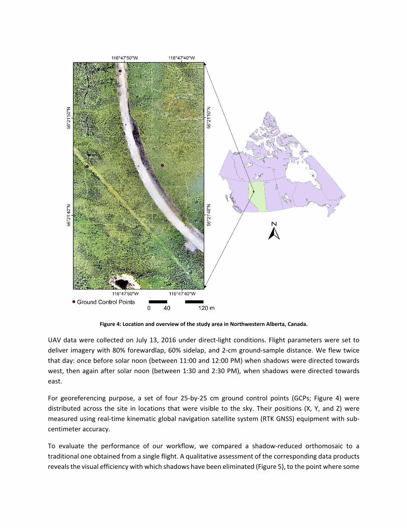
Figure 4: Location and overview of the study area in Northwestern Alberta, Canada.
UAV data were collected on July 13, 2016 under direct-light conditions. Flight parameters were set to deliver imagery with 80% forewardlap, 60% sidelap, and 2-cm ground-sample distance. We flew twice that day: once before solar noon (between 11:00 and 12:00 PM) when shadows were directed towards west, then again after solar noon (between 1:30 and 2:30 PM), when shadows were directed towards east.
For georeferencing purpose, a set of four 25-by-25 cm ground control points (GCPs; Figure 4) were distributed across the site in locations that were visible to the sky. Their positions (X, Y, and Z) were measured using real-time kinematic global navigation satellite system (RTK GNSS) equipment with sub-centimeter accuracy.
To evaluate the performance of our workflow, we compared a shadow-reduced orthomosaic to a traditional one obtained from a single flight. A qualitative assessment of the corresponding data products reveals the visual efficiency with which shadows have been eliminated (Figure 5), to the point where some

ground features (trees, for example) are difficult to identify without their corresponding shadows. The performance of the workflow was confirmed with a quantitative assessment, wherein we classified the raw orthomosaic into two classes – shadow and other – using an unsupervised (K-Means) decision rule. An assessment of the accuracy of this classification was performed using randomly selected shadow (70 nos.) and other class sample points (70 nos.). The reported classification accuracy was 96% with a kappa of 0.91. According to our classification, 22.3% of the study area was covered by shadow in the raw orthomosaic. From a visual assessment, a complete lack of shadow was observed on the shadow treated orthomosaic. The following sections briefly describe how the shadow-treated orthomosaic performed under different conditions.
Figure 5: A visual comparison of shadow-reduced (right) and raw (left) orthomosaics of scenes within the study area.

3.1 Seamless Performance of the Orthomosaic
We inspected shadow-treated orthomosaics for seams or other unwanted side-effects of our workflow in two locations: (i) at the edge of former shadows, and (ii) at the border of individual photos. At the edge of former shadows, we observed consistently smooth and seamless blends, with no hard boundaries or other unwanted artefacts. For example, Figures 6 display areas of ground vegetation surface objects that were obscured by shadow in the raw orthomosaic (Figure 6A) but are clearly and seamlessly visible in the shadow-treated orthomosaic (Figure 6B). The same is true of more complex situations, such as the previously obscured equipment and ground features (Figure 6C) that are fully and seamlessly visible following shadow treatment (Figure 6D). No signed of unwanted degradation were noted.
Figure 6: Example of seamless performance of shadow treated orthomosaic under shadows.
The border of individual photos was another area of potential concern. In general, we found both the raw orthomosaic and the shadow-treated orthomosaic to display seamless borders at the edge of individual photos (Figure 7). However, when it was not possible to collect two adjacent image under similar lighting conditions, the shadow-treated orthomosaic was observed to perform better than the original orthomosaic. Figure 8 shows such an example, where one of the photo was captured under diffuse-light conditions with no hard shadow (sun temporarily obscured by a cloud), and the adjacent photo was

captured under direct sunlight with hard shadows of elevated objects on the ground. When the shadow was not treated, a clear radiometric difference was observed (Figure 8A). Conversely, the shadow-treated orthomosaic was able to produce a visually seamless mosaic of the same area (Figure 8B). This might be because the dynamic data range of a photo with hard shadow is much larger than that of the adjacent photo that is captured under diffuse-light conditions, making it difficult for the radiometric normalization algorithm to fit them to a similar data range. On the other hand, when the shadow is masked out (in case of shadow-treated orthomosaic) the dynamic data range of the photo with hard shadow narrows, and become more similar to a photo that is captured under diffuse-light conditions. Thus, it becomes easier to radiometrically normalize such photos to one another.
Figure 7: A comparison of seamless performance between the raw orthomosaic (bottom) and the shadow-treated orthomosaic (top) at photo borders. The red dashed lines display photo borderlines. A seamless blend between photos is
observed in both orthomosaics.

Figure 8: A comparison of performance between the raw orthomosaic and the shadow-treated orthomosaic, when data is collected under varying light conditions. The shadow-treated orthomosaic (right) displays better radiometric matching than
the raw orthomosaic (left).
3.2 Complex Shadows
In areas where the canopy was very dense, a complex mixture of shadow made it difficult to observe the ground even when the data was collected at two different times of the day. In cases like this, the sides of elevated objects (e.g., trees) often replaced the ground in the shadow-treated orthomosaic (Figure 9). This problem could be minimized by decreasing the FOV (field of view), increasing overlaps, and/or masking out a certain percent of the input photos along the edges.

Figure 9: The performance of the shadow-treated orthomosaic degrades somewhat when the ground is never visible from an aerial platform, despite time of day.
4.0 Summary
Compensating for shadows using multi-temporal imagery is normally constrained by three main factors: (i) geometric mismatch, (ii) radiometric mismatch, and (iii) cost. Our workflow using multi-flight UAV data minimizes the influence of all three factors. For example, image mosaicking is traditionally performed using a superimposing method (Rahman et al. 2013), based on geometric location of individual pixels within the photos or scenes. This strategy focuses geometric distortion (caused primarily by errors in the GCPs and georeferencing model) along seam lines. By contrast, the high overlap (60-90%) delivered by UAV flights permits the use of a feature-matching mosaicking strategy. Feature matching identifies distinct features within the photos and uses their relative location to warp and mosaic them together. As a result, the final product is seamless.
Compensation for shadows using multitemporal imagery is usually done with historical data, with images acquired from a different date. Consequently, the radiometry among image dates is expected to vary due to phenological changes, varied sun-surface-sensor geometry, and environmental conditions, making it difficult to produce a seamless mosaic. In contrast, UAV platforms are able to collect data quickly and repeatedly, delivering data with similar illumination conditions and same-day target status.
It is perhaps unfair to compare the cost of piloted aircraft or satellite platforms to that of a UAV. However, the negligible set-up and operating cost of a UAV system allows for rapid, repetitive, and on-demand data collection to meet the needs of producing high-quality, shadow-free orthomosaics.
Our straightforward workflow capitalizes on the strengths and flexibility of the UAV platform, and is capable of detecting and reliably compensating for shadows across a vegetated study area. We characterize the shadow in our study area as complex, since their size, shape, and orientation varies abruptly. We look forward to future applications of this workflow to other natural and urban settings.

5.0 Acknowledgement
Research funding was provided by Emissions Reduction Alberta (Grant # BI40020) and Shell Canada Ltd. We also thank Shell Canada for site access and logistical support, NAIT Boreal Research Institute and the University of Waterloo for assisting with project design and facilitating field data collecting. The authors declare no conflict of interest. The founding sponsors had no role in the design of the study; in the collection, analyses, or interpretation of data; in the writing of the manuscript, and in the decision to publish the results.
6.0 References
Bendea, H., Boccardo, P., Dequal, S., Giulio Tonolo, F., Marenchino, D., and Piras, M. 2008. Low cost UAV for post-disaster assessment. The International Archives of the Photogrammetry, Remote Sensing and Spatial Information Sciences, 37(B8): 1373-1379.
Dare, P.M. 2005. Shadow analysis in high-resolution satellite imagery of urban areas. Photogrammetric Engineering and Remote Sensing, 71(2): 169-177.
Goetz, S.J., Wright, R.K., Smith, A.J., Zinecker, E., and Schaub, E. 2003. IKONOS imagery for resource management: Tree cover, impervious surfaces, and riparian buffer analyses in the mid-Atlantic region. Remote Sensing of Environment, 88(1): 195-208.
Li, Y., Gong, P., and Sasagawa, T. 2005. Integrated shadow removal based on photogrammetry and image analysis. International Journal of Remote Sensing, 26(18): 3911-3929.
Li, H., Zhang, L., and Shen, H. 2014. An adaptive nonlocal regularized shadow removal method for aerial remote sensing images. IEEE Transactions on Geoscience and Remote Sensing, 52(1): 106-120.
Lillesand, T.M., Kiefer, R.W., and Chipman, J.W. 2008. Remote Sensing and Image Interpretation (6th ed.). Hoboken, NJ: Wiley.
Liu, W., and Yamazaki, F. 2012. Object-based shadow extraction and correction of high-resolution optical satellite images. IEEE Journal of Selected Topics in Applied Earth Observations and Remote Sensing, 5(4): 1296-1302.
Rahman, M.M., Hay, G.J., Couloigner, I., Hemachandran, B., Bailin, J., Zhang, Y., and Tam, A. 2013. Geographic object-based mosaicking (OBM) of high-resolution thermal airborne imagery (TABI-1800) to improve the interpretation of urban image objects. IEEE Geoscience and Remote Sensing Letters, 10(4): 918-922.
Rau, J., Chen, N.Y., and Chen, L.C. 2002. True orthophoto generation of built-up areas using multi-view images. Photogrammetric Engineering and Remote Sensing, 68(6): 581-588.
Roy, D. P., Ju, J., Lewis, P., Schaaf, C., Gao, F., Hansen, M., and Lindquist, E. 2008. Multi-temporal MODIS–Landsat data fusion for relative radiometric normalization, gap filling, and prediction of Landsat data. Remote Sensing of Environment, 112(6): 3112-3130.
Saha, A.K., Arora, M.K., Csaplovics, E., and Gupta, R.P. 2005. Land cover classification using IRS LISS III image and DEM in a rugged terrain: a case study in Himalayas. Geocarto International, 20(2): 33-40.
Sarabandi, P., Yamazaki, F., Matsuoka, M., and Kiremidjian, A. 2004. Shadow detection and radiometric restoration in satellite high resolution images. In Geoscience and Remote Sensing Symposium, 2004. IGARSS'04. Proceedings. 2004 IEEE International (6: 3744-3747). IEEE.

Shahtahmassebi, A., Yang, N., Wang, K., Moore, N., and Shen, Z. 2013. Review of shadow detection and de-shadowing methods in remote sensing. Chinese Geographical Science, 23(4): 403-420.
Shen, H., Li, X., Cheng, Q., Zeng, C., Yang, G., Li, H., and Zhang, L. 2015. Missing information reconstruction of remote sensing data: A technical review. IEEE Geoscience and Remote Sensing Magazine, 3(3): 61-85.
Shu, J.S.P. and Freeman, H. 1990. Cloud shadow removal from aerial photographs. Pattern Recognition, 23(6): 647-656.
SunCalc 2018. Citing online sources: advice on online citation formats [online]. Available from https://www.suncalc.org/ [Cited: October 2018].
Tong, X.H., Lin, X.F., Feng, T.T., Xie, H., Liu, S.J., Hong, Z.H., Chen, P., 2013. Use of shadows for detection of earthquake-induced collapsed buildings in high-resolution satellite imagery. ISPRS Journal of Photogrammetry and Remote Sensing 79: 53-67.
Wu, Q., Zhang, W., and Kumar, B. V. 2012. Strong shadow removal via patch-based shadow edge detection. 2012 IEEE International Conference on Robotics and Automation. May 14-18, 2012 St. Paul, MN, USA. pp. 2177-2182
Zarco-Tejada, P.J., Diaz-Varela, R., Angileri, V., Loudjani, P., 2014. Tree height quantification using very high resolution imagery acquired from an unmanned aerial vehicle (UAV) and automatic 3D photo-reconstruction methods. European Journal of Agronomy 55: 89-99.
Zhang, H., Sun, K., and Li, W. 2014. Object-oriented shadow detection and removal from urban high-resolution remote sensing images. IEEE Transactions on Geoscience and Remote Sensing, 52(11): 6972-6982.
Zhang, S., Chen, M., and Tang, J.S. 2012. Shadow Detecting and Shadow Interpolation Algorithm for InSAS. Advanced Materials Research, 605: 2121-2125.
Zhu, Z., and Woodcock, C.E. 2014. Continuous change detection and classification of land cover using all available Landsat data. Remote sensing of Environment, 144: 152-171.