
A Wireless Mesh IoT sensor system Vicotee Njord … Sheets/Vicotee PDFs/Vicotee... · Doc: 1100852...
20
Doc: 1100852 Vicotee Njord Nodes Datasheet Rev.B Release Date: 2016-11-02 Page 1 | 20 A Wireless Mesh IoT sensor system Vicotee Njord series Nodes FEATURES A SmartMesh IP network consists of a highly scalable self-forming multi-hop mesh of wireless nodes, known as motes, which collect and relay data, and a network manager that monitors and manages network performance and security, and exchanges data with a host application. > 99.999% Data Reliability even in harsh, dynamically changing RF environments Secured Network Makes traditional sensors wireless Covers most standard sensor interfaces Low Power – Runs on batteries for years Delivers real-time critical information Network Manager supports up to 100 nodes Mesh Network Node distances typical 50m WEB browser based Interface configuration DESCRIPTION Vicotee Njord Nodes, are Sensor and Sensor interface Units in a wireless mesh network system. The complete Network system also consists of a Wireless Gateway, and other system units (illustrated in Application example below). Mesh Network in Vicotee Njord Nodes is based on the SmartMesh IP Dust network from Linear Technology. Njord Nodes exists in several different models, all with basic sensors for: Temperature, Ambient Light, Humidity and Acceleration, both static and dynamic. Different models are equipped with optional MIB (Module Interface Board) Interfaces for connection to most types of sensors. Vicotee Njord Nodes are primary powered by embedded batteries that can last for several years, depending on connected sensors and measurement interval. Nodes with External power connection is also available. Flow Wireless Mesh Network Sensors / Actuators Wiring Application Example Pressure Gateway 10000 Regular Network Solutions Application User Vicotee Njord Node Ambient Light Temperature Humidity Accellerometer Njord Nodes Cloud Gas Basic Sensors MIB Interfaces (Optional)
Transcript of A Wireless Mesh IoT sensor system Vicotee Njord … Sheets/Vicotee PDFs/Vicotee... · Doc: 1100852...

Doc: 1100852 Vicotee Njord Nodes Datasheet Rev.B Release Date: 2016-11-02 P a g e 1 | 20
A Wireless Mesh IoT sensor system Vicotee Njord series Nodes
FEATURES
A SmartMesh IP network consists of a highly scalable self-forming multi-hop mesh of wireless nodes, known as motes, which collect and relay data, and a network manager that monitors and manages network performance and security, and exchanges data with a host application.
> 99.999% Data Reliability even in harsh, dynamically changing RF environments
Secured Network
Makes traditional sensors wireless
Covers most standard sensor interfaces
Low Power – Runs on batteries for years
Delivers real-time critical information
Network Manager supports up to 100 nodes
Mesh Network Node distances typical 50m
WEB browser based Interface configuration
DESCRIPTION
Vicotee Njord Nodes, are Sensor and Sensor
interface Units in a wireless mesh network system.
The complete Network system also consists of a
Wireless Gateway, and other system units
(illustrated in Application example below).
Mesh Network in Vicotee Njord Nodes is based on the
SmartMesh IP Dust network from Linear Technology.
Njord Nodes exists in several different models, all with
basic sensors for: Temperature, Ambient Light, Humidity
and Acceleration, both static and dynamic.
Different models are equipped with optional MIB
(Module Interface Board) Interfaces for connection to
most types of sensors.
Vicotee Njord Nodes are primary powered by embedded
batteries that can last for several years, depending on
connected sensors and measurement interval.
Nodes with External power connection is also available.
Flow
Wireless Mesh Network Sensors /
Actuators Wiring
Application Example
Pressure
Gateway
10000
Regular
Network
Solutions
Application
User
Vicotee Njord Node
Ambient Light
Temperature
Humidity
Accellerometer
Njord Nodes
Cloud
Gas
Basic
Sensors MIB
Interfaces
(Optional)
Doc: 1100852 Vicotee Njord Nodes Datasheet Rev.B Release Date: 2016-11-02 P a g e 2 | 20
Vicotee Njord series Nodes
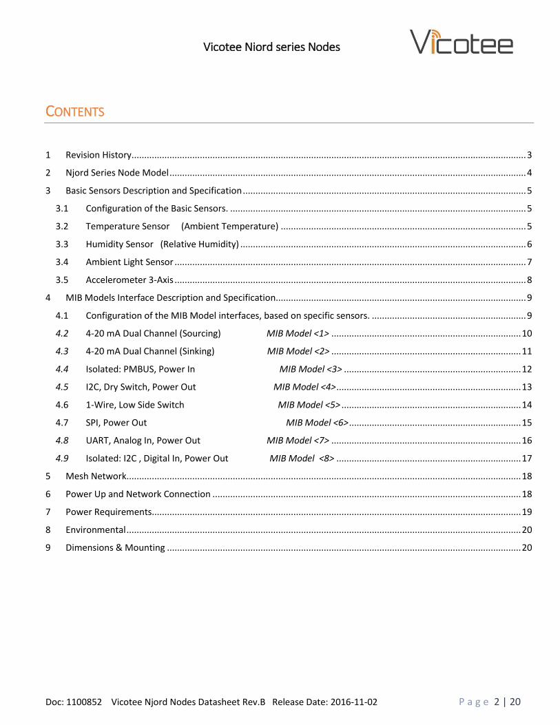
CONTENTS
1 Revision History ............................................................................................................................................................ 3
2 Njord Series Node Model ............................................................................................................................................. 4
3 Basic Sensors Description and Specification ................................................................................................................ 5
3.1 Configuration of the Basic Sensors. ..................................................................................................................... 5
3.2 Temperature Sensor (Ambient Temperature) ................................................................................................. 5
3.3 Humidity Sensor (Relative Humidity) ................................................................................................................. 6
3.4 Ambient Light Sensor ........................................................................................................................................... 7
3.5 Accelerometer 3-Axis ........................................................................................................................................... 8
4 MIB Models Interface Description and Specification................................................................................................... 9
4.1 Configuration of the MIB Model interfaces, based on specific sensors. ............................................................. 9
4.2 4-20 mA Dual Channel (Sourcing) MIB Model <1> ........................................................................... 10
4.3 4-20 mA Dual Channel (Sinking) MIB Model <2> ........................................................................... 11
4.4 Isolated: PMBUS, Power In MIB Model <3> ...................................................................... 12
4.5 I2C, Dry Switch, Power Out MIB Model <4> ......................................................................... 13
4.6 1-Wire, Low Side Switch MIB Model <5> ....................................................................... 14
4.7 SPI, Power Out MIB Model <6> .................................................................... 15
4.8 UART, Analog In, Power Out MIB Model <7> ........................................................................... 16
4.9 Isolated: I2C , Digital In, Power Out MIB Model <8> ......................................................................... 17
5 Mesh Network ............................................................................................................................................................ 18
6 Power Up and Network Connection .......................................................................................................................... 18
7 Power Requirements.................................................................................................................................................. 19
8 Environmental ............................................................................................................................................................ 20
9 Dimensions & Mounting ............................................................................................................................................ 20
Doc: 1100852 Vicotee Njord Nodes Datasheet Rev.B Release Date: 2016-11-02 P a g e 3 | 20
Vicotee Njord series Nodes
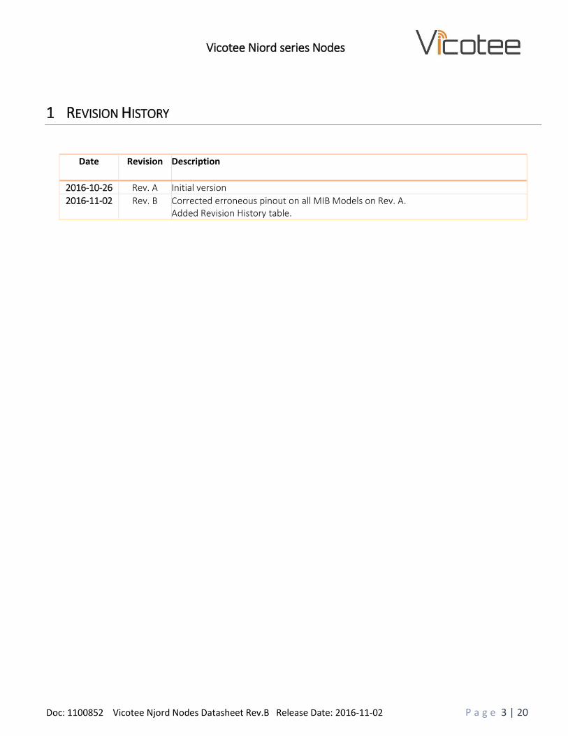
1 REVISION HISTORY
Date Revision Description
2016-10-26 Rev. A Initial version
2016-11-02 Rev. B Corrected erroneous pinout on all MIB Models on Rev. A. Added Revision History table.
Doc: 1100852 Vicotee Njord Nodes Datasheet Rev.B Release Date: 2016-11-02 P a g e 4 | 20
Vicotee Njord series Nodes
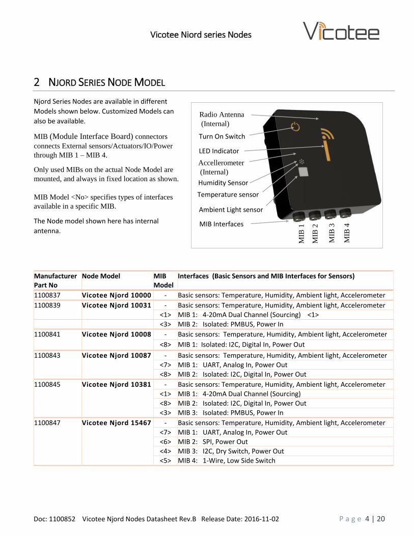
2 NJORD SERIES NODE MODEL
Manufacturer Part No
Node Model MIB Model
Interfaces (Basic Sensors and MIB Interfaces for Sensors)
1100837 Vicotee Njord 10000 - Basic sensors: Temperature, Humidity, Ambient light, Accelerometer
1100839 Vicotee Njord 10031
- Basic sensors: Temperature, Humidity, Ambient light, Accelerometer
<1> MIB 1: 4-20mA Dual Channel (Sourcing) <1>
<3> MIB 2: Isolated: PMBUS, Power In
1100841 Vicotee Njord 10008
- Basic sensors: Temperature, Humidity, Ambient light, Accelerometer
<8> MIB 1: Isolated: I2C, Digital In, Power Out
1100843 Vicotee Njord 10087
- Basic sensors: Temperature, Humidity, Ambient light, Accelerometer
<7> MIB 1: UART, Analog In, Power Out
<8> MIB 2: Isolated: I2C, Digital In, Power Out
1100845 Vicotee Njord 10381
- Basic sensors: Temperature, Humidity, Ambient light, Accelerometer
<1> MIB 1: 4-20mA Dual Channel (Sourcing)
<8> MIB 2: Isolated: I2C, Digital In, Power Out
<3> MIB 3: Isolated: PMBUS, Power In
1100847 Vicotee Njord 15467
- Basic sensors: Temperature, Humidity, Ambient light, Accelerometer
<7> MIB 1: UART, Analog In, Power Out
<6> MIB 2: SPI, Power Out
<4> MIB 3: I2C, Dry Switch, Power Out
<5> MIB 4: 1-Wire, Low Side Switch
Njord Series Nodes are available in different
Models shown below. Customized Models can
also be available.
MIB (Module Interface Board) connectors
connects External sensors/Actuators/IO/Power
through MIB 1 – MIB 4.
Only used MIBs on the actual Node Model are
mounted, and always in fixed location as shown.
MIB Model <No> specifies types of interfaces
available in a specific MIB.
The Node model shown here has internal
antenna.
Temperature sensor
Ambient Light sensor
Humidity Sensor
LED Indicator
Turn On Switch
Accellerometer
(Internal)
MIB
1
MIB
2
MIB
3
MIB
4
Radio Antenna
(Internal)
MIB Interfaces
Doc: 1100852 Vicotee Njord Nodes Datasheet Rev.B Release Date: 2016-11-02 P a g e 5 | 20
Vicotee Njord series Nodes
3 BASIC SENSORS DESCRIPTION AND SPECIFICATION
3.1 CONFIGURATION OF THE BASIC SENSORS.
Initially the different Sensors have some default functions, as described in this datasheet.
Further configuration of sensors are defined on system basis, through a configuration process on Vicotee Web Portal.
- Selection of optional function. (For the sensors with this possibility)
- Parameter setting for the selected function(s).
- Physical property unit of measurements.
This gives a freedom to use sensors in several different applications.
Just configure sensor in Vicotee Web Portal, and use sensor in your application.
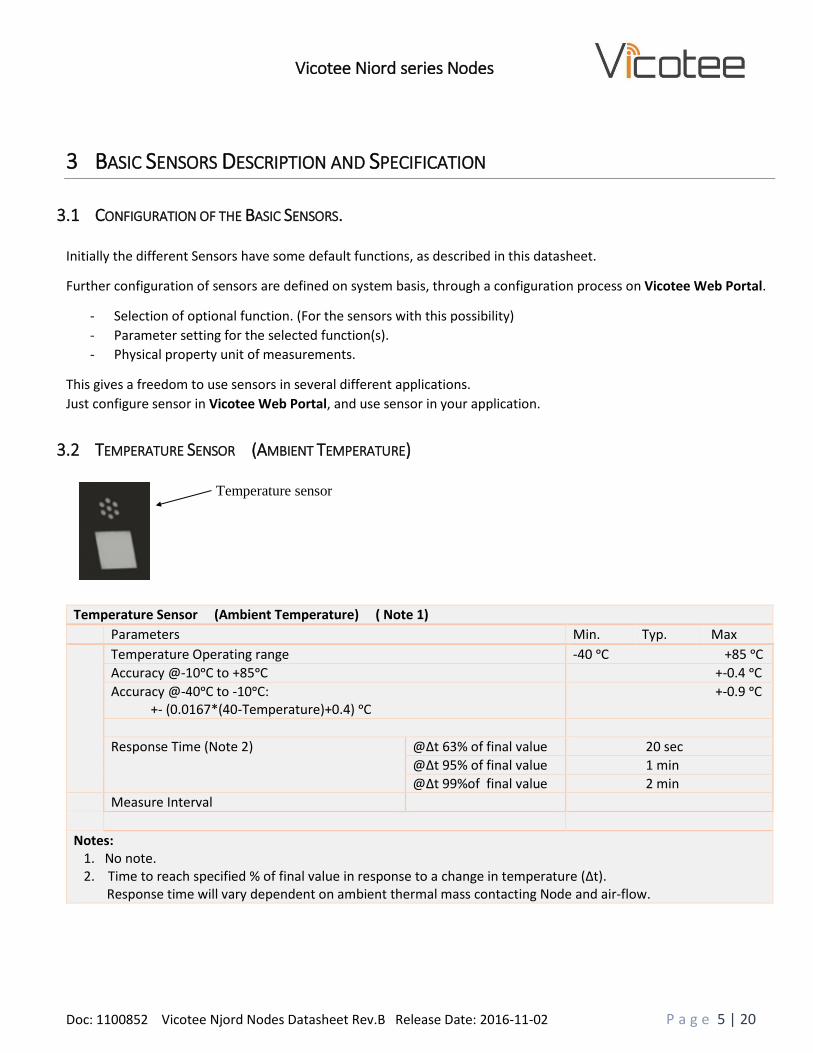
3.2 TEMPERATURE SENSOR (AMBIENT TEMPERATURE)
Temperature Sensor (Ambient Temperature) ( Note 1)
Parameters Min. Typ. Max
Temperature Operating range -40 ᵒC +85 ᵒC
Accuracy @-10ᵒC to +85ᵒC +-0.4 ᵒC
Accuracy @-40ᵒC to -10ᵒC: +- (0.0167*(40-Temperature)+0.4) ᵒC
+-0.9 ᵒC
Response Time (Note 2)
@∆t 63% of final value 20 sec
@∆t 95% of final value 1 min
@∆t 99%of final value 2 min
Measure Interval
Notes: 1. No note. 2. Time to reach specified % of final value in response to a change in temperature (∆t). Response time will vary dependent on ambient thermal mass contacting Node and air-flow.
Temperature sensor

Doc: 1100852 Vicotee Njord Nodes Datasheet Rev.B Release Date: 2016-11-02 P a g e 6 | 20
Vicotee Njord series Nodes
3.3 HUMIDITY SENSOR (RELATIVE HUMIDITY)
Humidity Sensor (Relative Humidity) ( Note 1)
Parameters Min. Typ. Max
Relative Humidity Operating Range (Note 2) 0% RH 100% RH
Accuracy @ 0-80%RH +-4% RH
Accuracy @ 80-100%RH +- (0.15*(%RH-80)+ 4) %RH
+-7% RH
Response time (Note 3) @ ∆RH 63% of final value 20 s
@ ∆RH 95% of final value 1 min
@ ∆RH 99% of final value 2 min
Measure Interval
Notes: 1. No note.
2. Recommended humidity operating range is 20% to 80% RH (non-condensing) over –10 °C to 60 °C. Prolonged operation beyond these ranges may result in a shift of sensor reading, with slow recovery time. 3. Time to reach specified % of final value in response to a change in Relative Humidity (∆RH). Response time will vary dependent on ambient air-flow.
Humidity sensor

Doc: 1100852 Vicotee Njord Nodes Datasheet Rev.B Release Date: 2016-11-02 P a g e 7 | 20
Vicotee Njord series Nodes
3.4 AMBIENT LIGHT SENSOR
Ambient Light Sensor (Note 1)
Parameters Min. Typ. Max
Spectral Response (Human Eye) 420nm 670nm
Peak Spectral Response 550nm
Light sensitivity
Range 0.0 lux 83865 lux
Resolution 20.48 lux
Normalized Light Sensitivity at different angles.
Θ = ±0ᵒ 1.0
Θ = ±30ᵒ 0.78
Θ = ±45ᵒ 0.5
Θ = ±70ᵒ 0.18
Measure Interval
Notes: 1. No note
Ambient Light
Window
Side view of
Ambient Light
incoming angle
Θ: ±45ᵒ
Θ Θ
Spectral Response
Doc: 1100852 Vicotee Njord Nodes Datasheet Rev.B Release Date: 2016-11-02 P a g e 8 | 20
Vicotee Njord series Nodes
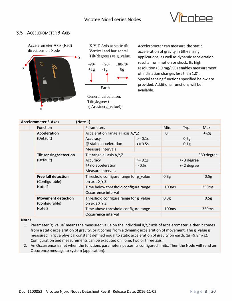
3.5 ACCELEROMETER 3-AXIS
Accelerometer 3-Axes (Note 1)
Function Parameters Min. Typ. Max
Acceleration (Default)
Acceleration range all axis A,Y,Z 0 +-2g
Accuracy @ stable acceleration
>= 0.1s 0,5g
>= 0.5s 0.1g
Measure Intervals
Tilt sensing/detection (Default)
Tilt range all axis A,Y,Z 360 degree
Accuracy @ no acceleration
>= 0.1s +- 3 degree
> 0.5s +- 2 degree
Measure Intervals
Free fall detection (Configurable) Note 2
Threshold configure range for g_value on axis X,Y,Z
0.3g 0.5g
Time below threshold configure range 100ms 350ms
Occurrence interval
Movement detection (Configurable) Note 2
Threshold configure range for g_value on axis X,Y,Z
0.3g 0.5g
Time above threshold configure range 100ms 350ms
Occurrence interval
Notes 1. Parameter ‘g_value’ means the measured value on the individual X,Y,Z axis of accelerometer, either it comes
from a static acceleration of gravity, or it comes from a dynamic acceleration of movement. The g_value is measured in ‘g’, a physical constant defined equal to static acceleration of gravity on earth. 1g =9.8m/s2. Configuration and measurements can be executed on one, two or three axis.
2. An Occurrence is met when the functions parameters passes its configured limits. Then the Node will send an Occurence message to system (application).
Z
Y
X
Accelerometer can measure the static
acceleration of gravity in tilt-sensing
applications, as well as dynamic acceleration
results from motion or shock. Its high
resolution (3.9 mg/LSB) enables measurement
of inclination changes less than 1.0°.
Special sensing functions specified below are
provided. Additional functions will be
available.
Accelerometer Axis (Red)
directions on Node X,Y,Z Axis at static tilt.
Vertical and horizontal
Tilt(degrees) vs g_value.
Earth
General calculation:
Tilt(degrees)=
(-Arcsine(g_value))◦
-90◦
+1g +90◦
-1g 180◦/0◦
0g

Doc: 1100852 Vicotee Njord Nodes Datasheet Rev.B Release Date: 2016-11-02 P a g e 9 | 20
Vicotee Njord series Nodes
4 MIB MODELS INTERFACE DESCRIPTION AND SPECIFICATION
4.1 CONFIGURATION OF THE MIB MODEL INTERFACES, BASED ON SPECIFIC SENSORS.
Initially the different interfaces on MIB Models are defined only in type, pinout, electrical parameters, etc.,
as described in this datasheet.
Configuration of interfaces are defined on system basis, through a configuration process on Vicotee Web Portal.
- Interface Variants
- Timing
- Protocol
- Physical property unit of measurements.
This gives a freedom to connect a multitude of sensor types, with different implementation of interfaces.
Just find the sensor(s) and interface specification, connect sensor, configure sensor in Vicotee Web Portal, and use
sensor in your application.

Doc: 1100852 Vicotee Njord Nodes Datasheet Rev.B Release Date: 2016-11-02 P a g e 10 | 20
Vicotee Njord series Nodes
4.2 4-20 MA DUAL CHANNEL (SOURCING) MIB MODEL <1>
Ch0 and Ch1 are identical, except for pinout.
The 4-20mA Current Loop receiver has Sourced Power to supply an external sensor with power.
4-20mA Ch0 / Ch1 DC Characteristics MIB Model <1>
Pin Signal Name Dir. Parameters Min. Typ. Max
3
2
4-20mA Ch0+ 4-20mA Ch1+
O
Sourced Power (Configurable for one of three different output voltages)
@ +6V +5.5V +6.0V +6.5V
@ +12V +11,0V +12.0V +13.0V
@ +24V +23,0V +24.0V +25.0V
Sourced Power change @ 4-20mA current variation 20mV 100mV
Internal High Side Current sense resistor 4,97 4.99 ohm 5,01
4
1
4-20mA Ch0- 4-20mA Ch1-
I
Current Return Voltage(VCR) @ ICR(MAX)=20mA 0.1V
Current Loop Accuracy 1%
Measurement Interval
Gnd / Shield DC Characteristics MIB Model <1>
Pin Signal Name Dir. Parameters Min. Typ. Max
5 Gnd - Voltage on Gnd (VGnd) by definition (Note 1) 0V 0V
Shield Shield - Voltage on Shield. (Internal connected to Gnd.) 0V 0V
Note 1: Gnd is the reference voltage for all signals/power on MIB Model <1>, if nothing else is specified.
Sensor Shield/Encapsulation
Signal Conditioning
Shield
GND
Power Sensor
Element
4-20mA
Connector and Cable
Sensor element example 4-20mA Ch0 + 3
4-20mA Ch0 - 4
4-20mA Ch1+ 2
4-20mA Ch1- 1
Gnd 5
Shield
Gnd
Gnd
Shield
MIB Connector
connecting side
MIB Model <1>
R= 4.99 ohm
+6V/12V/24V
R +6V/12V/24V
R
+ -
+ -
Shield
4-20mA Ch1 connection

Doc: 1100852 Vicotee Njord Nodes Datasheet Rev.B Release Date: 2016-11-02 P a g e 11 | 20
Vicotee Njord series Nodes
4.3 4-20 MA DUAL CHANNEL (SINKING) MIB MODEL <2>
TBD
Doc: 1100852 Vicotee Njord Nodes Datasheet Rev.B Release Date: 2016-11-02 P a g e 12 | 20
Vicotee Njord series Nodes
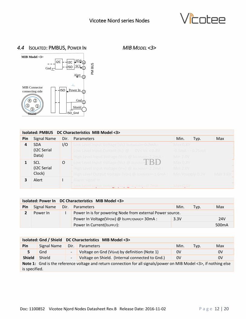
4.4 ISOLATED: PMBUS, POWER IN MIB MODEL <3>
Isolated: PMBUS DC Characteristics MIB Model <3>
Pin Signal Name Dir. Parameters Min. Typ. Max
4 SDA (I2C Serial Data)
I/O
Low Level Input Voltage (VIL): IIL(Typival)=-0.7mA : Max 0,8V
Low Level Input Current (IIL): @ 0V< VIL < 0.8V -0.5mA - - 0.75mA
High Level Input Voltage (VIH): @ IOL(MAX)=-2.2mA : Min 2.0V
1 SCL (I2C Serial Clock)
O Low Level Input Voltage (VIL): @ IIL(MAX)=-0.7mA : Max 0,8V
High Level Input Voltage (VIH): @ IOL(MAX)=-2.2mA : Min 2.0V
High Level Output Voltage (VOH) @ IOH(MAX)=-1.6mA : Min Vsupply-0.3V Max 3.6V
3 Alert I Alarm signal In
Low Level Input Voltage (VIL): @ IIL(MAX)=-0.7mA : Max 0,8V
Isolated: Power In DC Characteristics MIB Model <3>
Pin Signal Name Dir. Parameters Min. Typ. Max
2 Power In I
Power In is for powering Node from external Power source.
Power In Voltage(VPOW) @ ISUPPLY(MAX)= 30mA : 3.3V 24V
Power In Current(ISUPPLY): 500mA
Isolated: Gnd / Shield DC Characteristics MIB Model <3>
Pin Signal Name Dir. Parameters Min. Typ. Max
5 Gnd - Voltage on Gnd (VGnd) by definition (Note 1) 0V 0V
Shield Shield - Voltage on Shield. (Internal connected to Gnd.) 0V 0V
Note 1: Gnd is the reference voltage and return connection for all signals/power on MIB Model <3>, if nothing else is specified.
I2C
ISO
ISO_Gnd
SDA 4
SCL 1
Alert 3
Power In 2
Gnd 5
Shield
Gnd
Shield
MIB Connector
connecting side
MIB Model <3> I2C
PM
BU
S
Shield
ISO
TBD

Doc: 1100852 Vicotee Njord Nodes Datasheet Rev.B Release Date: 2016-11-02 P a g e 13 | 20
Vicotee Njord series Nodes
4.5 I2C, DRY SWITCH, POWER OUT MIB MODEL <4>
I2C DC Characteristics MIB Model <4>
Pin Signal Name Dir. Parameters Min. Typ. Max
4 SDA (I2C Serial Data)
I/O
Low Level Input Voltage (VIL): IIL(Typival)=-0.7mA : Max 0,8V
Low Level Input Current (IIL): @ 0V< VIL < 0.8V -0.5mA - - 0.75mA
1 SCL (I2C Serial Clock)
O
Low Level Input Voltage (VIL): @ IIL(MAX)=-0.7mA : Max 0,8V
High Level Input Voltage (VIH): @ IOL(MAX)=-2.2mA : Min 2.0V
Dry Switch DC Characteristics MIB Model <4>
Pin Signal Name Dir. Parameters Min. Typ. Max
3 Dry Switch I
Low Level Input Voltage (VIL): IIL(Typival)=-0.7mA : Max 0,8V
Power Out DC Characteristics MIB Model <4>
Pin Signal Name Dir. Parameters Min. Typ. Max
2 Power Out O
Power Out is for powering external connected sensors.
Power Out Voltage(VPOW) @ ISUPPLY(MAX)= 30mA : 2.8V 3.6V
Power Out Current(ISUPPLY): 30mA
Gnd / Shield DC Characteristics MIB Model <4>
Pin Signal Name Dir. Parameters Min. Typ. Max
5 Gnd - Voltage on Gnd (VGnd) by definition (Note 1) 0V 0V
Shield Shield - Voltage on Shield. (Internal connected to Gnd.) 0V 0V
Note 1: Gnd is the reference voltage and return connection for all signals/power on MIB Model <4>, if nothing else is specified.
I2C
GND
SDA 4
SCL 1
Dry Switch 3
Power Out 2
Gnd 5
Shield
Gnd
Shield
MIB Connector
connecting side
MIB Model <4>
Shield
TBD
Doc: 1100852 Vicotee Njord Nodes Datasheet Rev.B Release Date: 2016-11-02 P a g e 14 | 20
Vicotee Njord series Nodes
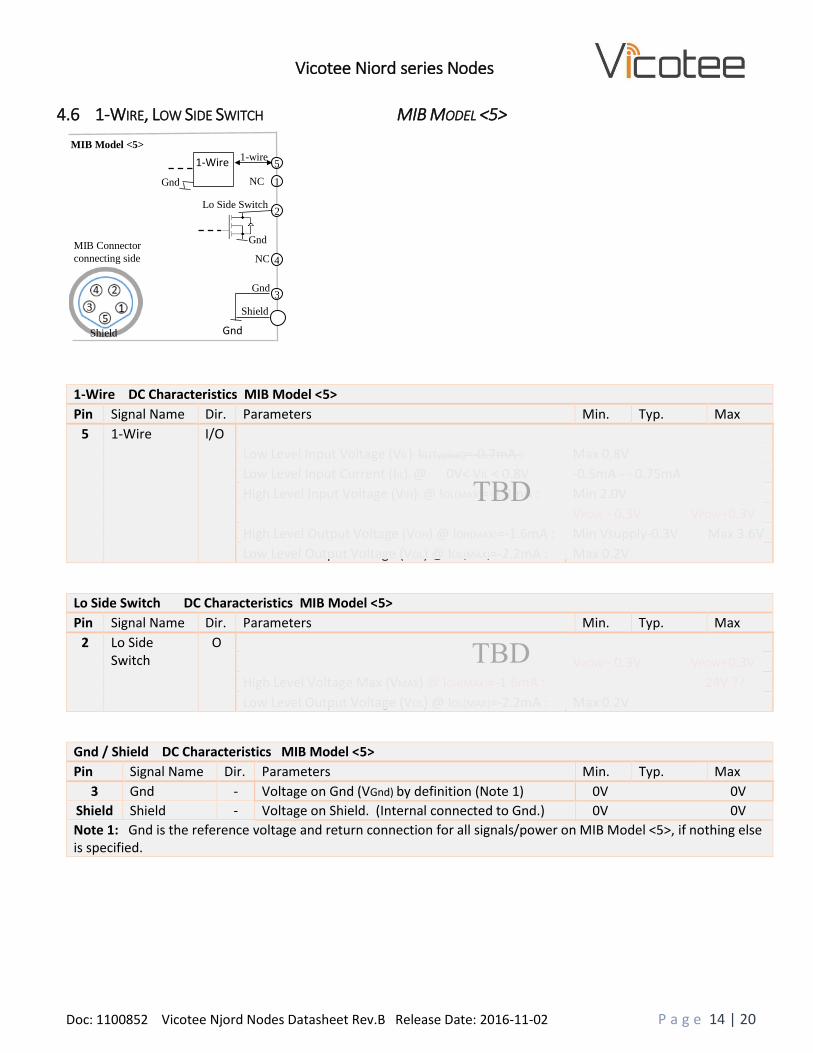
4.6 1-WIRE, LOW SIDE SWITCH MIB MODEL <5>
1-Wire DC Characteristics MIB Model <5>
Pin Signal Name Dir. Parameters Min. Typ. Max
5 1-Wire
I/O
Low Level Input Voltage (VIL): IIL(Typival)=-0.7mA : Max 0,8V
Low Level Input Current (IIL): @ 0V< VIL < 0.8V -0.5mA - - 0.75mA
High Level Input Voltage (VIH): @ IOL(MAX)=-2.2mA : Min 2.0V
VPOW - 0.3V VPOW+0.3V
High Level Output Voltage (VOH) @ IOH(MAX)=-1.6mA : Min Vsupply-0.3V Max 3.6V
Low Level Output Voltage (VOL) @ IOL(MAX)=-2.2mA : Max 0.2V
Lo Side Switch DC Characteristics MIB Model <5>
Pin Signal Name Dir. Parameters Min. Typ. Max
2 Lo Side Switch
O
VPOW - 0.3V VPOW+0.3V
High Level Voltage Max (VMAX) @ IOH(MAX)=-1.6mA : 24V ??
Low Level Output Voltage (VOL) @ IOL(MAX)=-2.2mA : Max 0.2V
Gnd / Shield DC Characteristics MIB Model <5>
Pin Signal Name Dir. Parameters Min. Typ. Max
3 Gnd - Voltage on Gnd (VGnd) by definition (Note 1) 0V 0V
Shield Shield - Voltage on Shield. (Internal connected to Gnd.) 0V 0V
Note 1: Gnd is the reference voltage and return connection for all signals/power on MIB Model <5>, if nothing else is specified.
1-Wire
Gnd
1-wire 5
NC 1
Lo Side Switch 2
NC 4
Gnd 3
Shield
Gnd
Gnd
Shield
MIB Connector
connecting side
MIB Model <5>
Shield

Doc: 1100852 Vicotee Njord Nodes Datasheet Rev.B Release Date: 2016-11-02 P a g e 15 | 20
Vicotee Njord series Nodes
4.7 SPI, POWER OUT MIB MODEL <6>
SPI DC Characteristics MIB Model <6>
Pin Signal Name Dir. Parameters Min. Typ. Max
4 MOSI (Master Out Slave In)
O
High Level Output Voltage (VOH) @ IOH(MAX)=-1.6mA : VPOW - 0.3V VPOW+0.3V
Low Level Output Voltage (VOL) @ IOL(MAX)=-2.2mA : +0.2V
5 MISO (Master In Slave Out)
I Low Level Input Voltage (VIL): @ IIL(MAX)=-0.7mA : -0.3V +0.6V
High Level Input Voltage (VIH): @ IOL(MAX)=-2.2mA : +2.0V Vout+0.3V
1 SCLK (Slave Clock)
O High Level Output Voltage (VOH) @ IOH(MAX)=-1.6mA : VPOW - 0.3V VPOW+0.3V
Low Level Output Voltage (VOL) @ IOL(MAX)=-2.2mA : +0.2V
3 SS (Slave Select)
O High Level Output Voltage (VOH) @ IOH(MAX)=-1.6mA : VPOW - 0.3V VPOW+0.3V
Low Level Output Voltage (VOL) @ IOL(MAX)=-2.2mA : 0.2V
Power Out DC Characteristics MIB Model <6>
Pin Signal Name Dir. Parameters Min. Typ. Max
2 Power Out O
Power Out is for powering external connected sensors.
Power Out Voltage(VPOW) @ ISUPPLY(MAX)= 30mA : 2.8V 3.6V
Power Out Current(ISUPPLY): 30mA
Gnd / Shield DC Characteristics MIB Model <6>
Pin Signal Name Dir. Parameters Min. Typ. Max
- Gnd - Gnd is not on connector. Only internal in MIB
Voltage on Gnd (VGnd) by definition (Note 1) 0V 0V
Shield Shield - Voltage on Shield. (Internal connected to Gnd.) 0V 0V
Note 1: Gnd/Shield is the reference voltage and return connection for all signals/power on MIB Model <6>, if nothing else is specified. Note 2: Shield must be used for external Gnd connections, since there is no separate Gnd pin In this MIB Model.
SPI
Gnd
MOSI 4
MISO 5
SCLK 1
Power Out 2
(Vpow)
SS 3
Shield
Gnd
Gnd
Shield
MIB Connector
connecting side
MIB Model <6>
Shield

Doc: 1100852 Vicotee Njord Nodes Datasheet Rev.B Release Date: 2016-11-02 P a g e 16 | 20
Vicotee Njord series Nodes
4.8 UART, ANALOG IN, POWER OUT MIB MODEL <7>
UART DC Characteristics MIB Model <7>
Pin Signal Name Dir. Parameters Min. Typ. Max
4 Tx (Transmit Data)
O
High Level Output Voltage (VOH) @ IOH(MAX)=-1.6mA : VPOW - 0.3V VPOW+0.3V
Low Level Output Voltage (VOL) @ IOL(MAX)=-2.2mA : +0.2V
1 Rx (Receive Data)
I Low Level Input Voltage (VIL): @ IIL(MAX)=-0.7mA : -0.3V +0.6V
High Level Input Voltage (VIH): @ IOL(MAX)=-2.2mA : +2.0V Vout+0.3V
Analog In DC Characteristics MIB Model <7>
Pin Signal Name Dir. Parameters Min. Typ. Max
5 Analog In
I
Analog Voltage In
Input Voltage ranges (Vin) More than one range? 0V 10V
Resolution 10 bit
Power Out DC Characteristics MIB Model <7>
Pin Signal Name Dir. Parameters Min. Typ. Max
2 Power Out O
Power Out is for powering external connected sensors.
Power Out Voltage(VPOW) @ ISUPPLY(MAX)= 30mA : 2.8V 3.6V
Power Out Current(ISUPPLY): 30mA
Gnd / Shield DC Characteristics MIB Model <7>
Pin Signal Name Dir. Parameters Min. Typ. Max
3 Gnd - Voltage on Gnd (VGnd) by definition (Note 1) 0V 0V
Shield Shield - Voltage on Shield. (Internal connected to Gnd.) 0V 0V
Note 1: Gnd is the reference voltage and return connection for all signals/power on MIB Model <7>, if nothing else is specified.
UART
GND
Tx 4
Rx 1
Analog In 5
+3.3V Power Out 2
Gnd 3
Shield
Gnd
Gnd
Shield
MIB Connector
connecting side
MIB Model <7>
+ -
Shield
TBD
TBD
Doc: 1100852 Vicotee Njord Nodes Datasheet Rev.B Release Date: 2016-11-02 P a g e 17 | 20
Vicotee Njord series Nodes
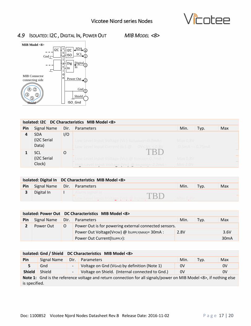
4.9 ISOLATED: I2C , DIGITAL IN, POWER OUT MIB MODEL <8>
Isolated: I2C DC Characteristics MIB Model <8>
Pin Signal Name Dir. Parameters Min. Typ. Max
4 SDA (I2C Serial Data)
I/O
Low Level Input Voltage (VIL): IIL(Typival)=-0.7mA : Max 0,8V
Low Level Input Current (IIL): @ 0V< VIL < 0.8V -0.5mA - - 0.75mA
1 SCL (I2C Serial Clock)
O
Low Level Input Voltage (VIL): @ IIL(MAX)=-0.7mA : Max 0,8V
High Level Input Voltage (VIH): @ IOL(MAX)=-2.2mA : Min 2.0V
Isolated: Digital In DC Characteristics MIB Model <8>
Pin Signal Name Dir. Parameters Min. Typ. Max
3 Digital In I Alarm signal In
Low Level Input Voltage (VIL): @ IIL(MAX)=-0.7mA : Max 0,8V
Isolated: Power Out DC Characteristics MIB Model <8>
Pin Signal Name Dir. Parameters Min. Typ. Max
2 Power Out O
Power Out is for powering external connected sensors.
Power Out Voltage(VPOW) @ ISUPPLY(MAX)= 30mA : 2.8V 3.6V
Power Out Current(ISUPPLY): 30mA
Isolated: Gnd / Shield DC Characteristics MIB Model <8>
Pin Signal Name Dir. Parameters Min. Typ. Max
5 Gnd - Voltage on Gnd (VGnd) by definition (Note 1) 0V 0V
Shield Shield - Voltage on Shield. (Internal connected to Gnd.) 0V 0V
Note 1: Gnd is the reference voltage and return connection for all signals/power on MIB Model <8>, if nothing else is specified.
I2C
ISO
ISO_Gnd
SDA 4
SCL 1
Power Out 2
Gnd 5
Shield
Gnd
Shield
MIB Connector
connecting side
MIB Model <8> I2C
Dig
In
Isolation
Shield
3 Digital
In
TBD
TBD

Doc: 1100852 Vicotee Njord Nodes Datasheet Rev.B Release Date: 2016-11-02 P a g e 18 | 20
Vicotee Njord series Nodes
5 MESH NETWORK
Mesh Networking in Vicotee Njord Nodes is based on the SmartMesh IP Dust network from Linear Technology. A SmartMesh IP network consists of a self-forming multi-hop mesh of nodes, known as motes, which collect and relay data, and a network manager that monitors and manages network performance and security, and exchanges data with a host application.
Radio specification
Parameter Condition Min Typ Max Units Frequency Band 2.4000 2.4835 GHz
Transmitter Output Power High Calibrated Setting Low Calibrated Setting
Delivered to a 50Ω load 8 0
dBm dBm
Receiver Sensitivity Packet Error Rate (PER) = 1% –93 dbm
Receiver Saturation Maximum Input Level the Receiver Will Properly Receive Packets
0 dBm
Range (Note 1) 50 m
Notes:
1. Actual RF range is subject to a number of installation-specific variables including, but not restricted to ambient temperature, relative humidity, presence of active interference sources, line-of-sight obstacles, and near-presence of objects (for example, trees, walls, signage, and soon) that may induce multipath fading. As a result, range varies.
6 POWER UP AND NETWORK CONNECTION
Turn On Switch Note:
Before Powering On, the Node must be registered in the Vicotee WEB Portal.
Follow Startup instructions in Vicotee User Manual before going further.
Node is Powered On (activated) by pressing Turn On Switch for 1-2 s.
This is verified by a flashing sequence in the LED Indicator.
The LED Indicator will flash until connection has been established.
The only way to turn off the Node is now through Vicotee WEB Portal.
LED Indicator

Doc: 1100852 Vicotee Njord Nodes Datasheet Rev.B Release Date: 2016-11-02 P a g e 19 | 20
Vicotee Njord series Nodes
7 POWER REQUIREMENTS
Power requirement pr. Node varies depending node and network configuration.
Main affecting parameters are:
- Types of sensors connected and activated
- Number of sensors connected and activated
- Measurement Intervals
Node Power Requirement
Parameter Condition Min Typ Max Quiescent current (No external sensors)
Network connected. No Network communication. (Note 1)
50 uA
Peak current (No external sensors)
Network connected. Network communication. No external sensors (Note 2) @ 10ms pr. Measurement interval
10mA
Mean current (No external sensors) Basic Node
Network connected. Network communication. No external sensors (Note 2) @ 20ms pr. Measurement interval.
1 s 300uA
10 s 120 uA
1 min 103 uA
2 min 102 uA
5 min
Total Mean current (4 pcs Low Current (1mA) sensors)
Network connected. Network communication. 4 pcs. external Low Current (1mA) sensors @ 20ms pr. Measurement interval.
1 s 380 uA
10 s 130 uA
1 min 110uA
2 min 102uA
5 min 101 uA
Mean current (4 pcs High Current (20mA) sensors)
Network connected. Network communication. 4 pcs. external High Current (20mA) sensors @ 20ms pr. Measurement interval.
1 s 1,9 mA
10 s 280 uA
1 min 130 uA
2 min 120 uA
5 min 110 uA
Notes: 1. When connected to network, but the network is at a minimum of activity, no sensor data transfer, just network maintaining. 2. Ongoing Network communication lasts for just about 10ms for each measurement interval (packet transfer). This period is called Peak
Current. In time between Network communications, Power requirements are close to quiescent current

Doc: 1100852 Vicotee Njord Nodes Datasheet Rev.B Release Date: 2016-11-02 P a g e 20 | 20
Vicotee Njord series Nodes
8 ENVIRONMENTAL
Parameter Condition Min Typ Max Units Storage Temperature Range
-20 70 oC
Operating Temperature Range
-20 50 oC
Temperature Ramp Rate While operating in Network -8 +8 oC/Min
Storage and Operating Relative Humidity Non-Condensing
90 %RH
Protection rating IP66
9 DIMENSIONS & MOUNTING
32 mm
86
mm
70
mm
43 mm
88 mm 4 pcs. Magnets for magnetic
mounting of Node
Magnet
Magnet
Magnet
Magnet


![R-30ia Karel Reference Manual [Ver.7.30][Marrcrlrf04071e Rev.b]](https://static.fdocuments.in/doc/165x107/53fc16c0dab5ca5d298b4599/r-30ia-karel-reference-manual-ver730marrcrlrf04071e-revb.jpg)


