A Tutorial on the Implementation of Block Ciphers ...
80
A Tutorial on the Implementation of Block Ciphers: Software and Hardware Applications Howard M. Heys Memorial University of Newfoundland, St. John’s, Canada email: [email protected] Dec. 10, 2020
Transcript of A Tutorial on the Implementation of Block Ciphers ...

A Tutorial on the
Implementation of Block Ciphers:
Software and Hardware Applications
Howard M. Heys
Memorial University of Newfoundland, St. John’s, Canadaemail: [email protected]
Dec. 10, 2020

2
Abstract
In this article, we discuss basic strategies that can be used to implement block ciphers inboth software and hardware environments. As models for discussion, we use substitution-permutation networks which form the basis for many practical block cipher structures. Forsoftware implementation, we discuss approaches such as table lookups and bit-slicing, whilefor hardware implementation, we examine a broad range of architectures from high speedstructures like pipelining, to compact structures based on serialization. To illustrate differentimplementation concepts, we present example data associated with specific methods anddiscuss sample designs that can be employed to realize different implementation strategies.We expect that the article will be of particular interest to researchers, scientists, andengineers that are new to the field of cryptographic implementation.
3

4

Terminology and Notation
Abbreviation DefinitionSPN substitution-permutation networkIoT Internet of ThingsAES Advanced Encryption StandardECB electronic codebook modeCBC cipher block chaining modeCTR counter mode
CMOS complementary metal-oxide semiconductorASIC application-specific integrated circuitFPGA field-programmable gate array
Table 1: Abbreviations Used in Article
5

6
Variable DefinitionB plaintext/ciphertext block size
(also, size of cipher state)κ number of cipher key bits
(also, size of key state)R number of roundsn S-box size (number of input/output bits)
P = [pB−1...p1p0] plaintext block of B bitsC = [cB−1...c1c0] ciphertext block of B bitsK = [kκ−1...k1k0] κ-bit cipher keyD = [dB−1...d1d0] B-bit cipher stateD∗ = [d∗B−1...d
∗1d∗0] B-bit next cipher state
X = [xB−1...x1x0] B-bit cipher state at input to substitution layerand output of key mixing layer
Y = [yB−1...y1y0] B-bit cipher state at output of substitution layerand input to permutation layer
Z = [zB−1...z1z0] B-bit cipher state at output of permutation layerand input to key mixing layer
RKr = [rkr,B−1...rkr,1rkr,0] B-bit round key of round rK ′ = [k′κ−1...k
′1k′0] κ-bit key state
P † = [P †B−1...P†1P†0 ]T bit-slice plaintext structure:
B ×B matrix of bits consisting of B rows of
B-bit plaintext blocks, P †i , i ∈ {0, 1, ..., B − 1}p†i,j element at row i, column j of P †, i, j ∈ {0, 1, ..., B − 1}
C† = [C†B−1...C†1C†0 ]T bit-slice ciphertext structure:
B ×B matrix of bits consisting of B rows of
B-bit ciphertext blocks, C†i , i ∈ {0, 1, ..., B − 1}D† = [D†B−1...D
†1D†0]T bit-slice cipher state:
B ×B matrix of bits consisting of B columns of
B-bit cipher states, D†i , i ∈ {0, 1, ..., B − 1}d†i,j element at row i, column j of D†, i, j ∈ {0, 1, ..., B − 1}
Table 2: Notation Used in Article
Contents
1 Introduction to Block Ciphers 9
1.1 Target Implementation Environments . . . . . . . . . . . . . . . . . . . . . . 9
1.2 Basic Cipher Principles . . . . . . . . . . . . . . . . . . . . . . . . . . . . . . 11
1.3 Substitution Permutation Networks . . . . . . . . . . . . . . . . . . . . . . . . 12
1.3.1 16-bit SPN . . . . . . . . . . . . . . . . . . . . . . . . . . . . . . . . . 12
1.3.2 64-bit SPN . . . . . . . . . . . . . . . . . . . . . . . . . . . . . . . . . 17
1.4 Modes of Operation . . . . . . . . . . . . . . . . . . . . . . . . . . . . . . . . 18
1.4.1 Electronic CodeBook Mode . . . . . . . . . . . . . . . . . . . . . . . . 19
1.4.2 Cipher Block Chaining Mode . . . . . . . . . . . . . . . . . . . . . . . 20
1.4.3 Counter Mode . . . . . . . . . . . . . . . . . . . . . . . . . . . . . . . 20
1.5 General Implementation Structures . . . . . . . . . . . . . . . . . . . . . . . . 21
1.6 Summary . . . . . . . . . . . . . . . . . . . . . . . . . . . . . . . . . . . . . . 23
2 Software Implementation 25
2.1 Structure of Encryption . . . . . . . . . . . . . . . . . . . . . . . . . . . . . . 25
2.2 Structure of Decryption . . . . . . . . . . . . . . . . . . . . . . . . . . . . . . 26
2.3 Direct Implementation of an SPN . . . . . . . . . . . . . . . . . . . . . . . . . 27
2.3.1 Key Mixing Layer Implementation . . . . . . . . . . . . . . . . . . . . 28
2.3.2 Substitution Layer Implementation . . . . . . . . . . . . . . . . . . . . 28
2.3.3 Permutation Layer Implementation . . . . . . . . . . . . . . . . . . . . 28
2.4 Table Lookup Implementations . . . . . . . . . . . . . . . . . . . . . . . . . . 29
2.4.1 Permutation in a Table . . . . . . . . . . . . . . . . . . . . . . . . . . 29
2.4.2 Combined Substitution/Permutation Table . . . . . . . . . . . . . . . 30
2.5 Time/Memory Tradeoffs of Lookup Tables . . . . . . . . . . . . . . . . . . . . 33
2.6 Bit-slice Implementations . . . . . . . . . . . . . . . . . . . . . . . . . . . . . 35
2.6.1 Bit-slicing the S-box . . . . . . . . . . . . . . . . . . . . . . . . . . . . 36
2.6.2 Restructuring the Data for Bit-Slicing . . . . . . . . . . . . . . . . . . 39
2.6.3 Bit-slicing the Permutation and Key Mixing . . . . . . . . . . . . . . . 41
2.6.4 Example of Bit-Slicing . . . . . . . . . . . . . . . . . . . . . . . . . . . 42
2.6.5 Other Structures for Bit-slicing . . . . . . . . . . . . . . . . . . . . . . 45
2.7 Software Implementation of Cipher Modes . . . . . . . . . . . . . . . . . . . . 46
2.8 Summary . . . . . . . . . . . . . . . . . . . . . . . . . . . . . . . . . . . . . . 47
7
8 CONTENTS
3 Hardware Implementation 493.1 Iterative Design . . . . . . . . . . . . . . . . . . . . . . . . . . . . . . . . . . . 50
3.1.1 Basic Iterative Architecture . . . . . . . . . . . . . . . . . . . . . . . . 503.1.2 Round Function Hardware . . . . . . . . . . . . . . . . . . . . . . . . . 523.1.3 Loop Unrolling . . . . . . . . . . . . . . . . . . . . . . . . . . . . . . . 53
3.2 Parallelization - A High Speed Implementation . . . . . . . . . . . . . . . . . 553.3 Pipelining - A High Speed Implementation . . . . . . . . . . . . . . . . . . . . 56
3.3.1 Description of Pipeline Architecture . . . . . . . . . . . . . . . . . . . 563.3.2 Selecting Hardware for a Pipeline Stage . . . . . . . . . . . . . . . . . 583.3.3 Timing Issues for Pipeline Designs . . . . . . . . . . . . . . . . . . . . 583.3.4 Example of Pipelining . . . . . . . . . . . . . . . . . . . . . . . . . . . 59
3.4 Serial Design - A Compact Implementation . . . . . . . . . . . . . . . . . . . 603.4.1 The Concept of Serialization . . . . . . . . . . . . . . . . . . . . . . . 613.4.2 A Sample Design . . . . . . . . . . . . . . . . . . . . . . . . . . . . . . 613.4.3 Selectable Register . . . . . . . . . . . . . . . . . . . . . . . . . . . . . 63
3.5 Hardware Implementation of Decryption . . . . . . . . . . . . . . . . . . . . . 653.6 Hardware Implementation of Cipher Modes . . . . . . . . . . . . . . . . . . . 663.7 Tradeoffs Between Architectures . . . . . . . . . . . . . . . . . . . . . . . . . 663.8 Summary . . . . . . . . . . . . . . . . . . . . . . . . . . . . . . . . . . . . . . 69
4 Conclusion 71
References 73
Appendix: Key Scheduling 77
Chapter 1
Introduction to Block Ciphers
Block ciphers are the workhorse of security applications. Using a symmetric key approach,block cipher algorithms encrypt a block of plaintext bits (typically, 64 or 128 bits) to producean equally-sized block of ciphertext bits. These algorithms can be found in a broad range ofapplication environments and it is almost certainly true that the best known block cipher,the Advanced Encryption Standard (AES) [1][2], is the most applied cipher in the worldtoday.
1.1 Target Implementation Environments
Implementations of block ciphers can be divided into two broad categories: software andhardware. Software implementations make use of the instructions available on generalpurpose processors, while hardware implementations focus on designs at the level of logicgates and registers. Of course, within these two categories, there are many sub-categoriesdependent on the processor characteristics for software (eg. instruction set, word size,memory availability, etc.) and the technology for hardware (eg. CMOS application-specificintegrated circuits (ASICs) and field-programmable gate arrays (FPGAs)). Implementationchoices are invariably influenced by the objectives of the application and the features of thetargeted environment. This results in the consideration of factors such as speed and resourceconstraints including chip area, system memory, and device power or energy limitations.
As examples of the diversity of target environments, consider that block ciphers couldbe implemented for the following 3 sample scenarios:
1. a general purpose computer using a processor with a word size of 64-bits (that is,instructions use 64-bit operands and data is stored as 64-bit words),
2. a device targeted to an application for the Internet of Things (IoT), making use ofeither (a) a small processor (eg. a microcontroller) or (b) custom dedicated hardwareof limited area, and
3. a high speed communications gateway targeted to service many high speed dataconnections.
9

10 CHAPTER 1. INTRODUCTION TO BLOCK CIPHERS
Now, consider briefly for these different environments, the resources needed and the influencesof those resource requirements on the implementation of the block cipher. For the 64-bit general purpose computer, there is likely to be lots of memory and a comprehensiveinstruction set with a large word size for operands and in such implementations probablyspeed of encryption (or throughput) is of most interest. In contrast, the implementationtargeted to the IoT device would be fundamentally concerned with the constrained resourcessuch as memory and word size for a small processor or circuit area and power/energylimitations for a hardware implementation. Hence, for the IoT device, it is necessary toconsider lightweight cryptography [3] and, for the applications to which such a device istargeted, speed of the encryption process is usually not an important consideration. Lastly,for the high speed communications gateway, speed of encryption is so important that it isoften desirable to utilize custom designed hardware implementations that give the ability toprocess many different connections at high speeds.
Clearly, there are a breadth of potential applications and, as a result, there are manydifferent considerations when implementing ciphers. In many scenarios, different types ofimplementations could be employed within the same application. For example, an IoTdevice might interact with a software application on a general purpose computer. In somecircumstances, specially-targeted ciphers are proposed that are intended specifically for oneor more these environments. For example, many recently proposed block cipher algorithmsare considered lightweight, targeted specifically to implementation on constrained devices.In such cipher proposals, implementation approaches are often discussed by the cipherproponents. In practice, however, it is often desirable to have a cipher be applied to manydifferent environments, which may vary dramatically in the nature of their requirements.This is case, for example, for AES, which can be found in all manner of targeted environmentsfrom high speed software to compact hardware architectures. The near-ubiquity of AES haslead to processors with special instructions to facilitate encryption speedup [4] and thedevelopment of specialized hardware structures suitable for the specific components definedfor AES (for example, see [5]).
In this article, we choose to focus our discussions on the general principles that can beapplied to the implementations of ciphers on many different platforms. We do not get intodetails which are targeted to one particular cipher and, instead, describe approaches thatcan generally be applied to the majority of proposed block ciphers. The main objectiveof the article then is not to provide a detailed description of the implementation for aparticular cipher or ciphers, but instead present the principles that form the foundation forunderstanding how ciphers can be implemented. This is accomplished by using illustrativeexamples and sample designs of cipher implementations. This article is a starting point forthe cryptographic engineer wanting to have an understanding of the general structures andmethods found in implementations before the engineer delves more deeply into the possiblearchitectures suitable to their cipher of interest. To this end, we present a basic form ofblock cipher, referred to as the substitution-permutation network (SPN), which we then useas the basis of our discussion of implementation approaches.

1.2. BASIC CIPHER PRINCIPLES 11
1.2 Basic Cipher Principles
We first discuss some of the fundamental principles with which all block ciphers are designed.1
Block ciphers encrypt a block of plaintext, P , of size B bits by applying a key-dependenttransformation to produce an B-bit block of ciphertext, C. The key, K, is defined to be κbits in size, giving a key space with a total of 2κ possible keys. Block ciphers fall into thecategory of symmetric key cryptography. Such ciphers have the same key applied for bothencryption and decryption.
Typically, B ≥ 64. Compact, lightweight ciphers, such as the PRESENT block cipher [6],targeted to constrained systems environments (such as some devices for IoT), which requireimplementation efficiency but which can typically accommodate lower security levels, havesmaller block sizes of 64 bits, while ciphers like AES used for a broad range of applications,are usually expected to have higher security levels and large block sizes (eg. 128 bits). Blockciphers with very small block sizes (such as 32 bits) would not acceptable for any context,because a small block size may make a dictionary attack practical, where the attacker isable to acquire some known plaintext and corresponding ciphertext and build a table ofplaintext-ciphertext mappings for a system with a given secret key.
The key size, κ, must be large enough to ensure that a brute force or exhaustive key searchattack is not possible. In such an attack, knowledge of a small number of plaintext blocksand corresponding ciphertext blocks could be utilized by the attacker who can encrypt theplaintext with all possible keys to determine which key results in the corresponding knownciphertext. Using only a modest number of plaintext/ciphertext pairs, the key found can beconfirmed to be the correct one. To prevent this, generally, κ ≥ 80, with the lower boundbeing suitable for low security lightweight applications, while values like κ = 128 or 256would be used for higher security general applications. For example, the PRESENT cipheris defined to operate with 80 or 128 bits of key and AES allows keys of 128, 192, and 256bits in size.
Cryptography has been around for millenia, but in the 1940s, Claude Shannon wasthe first to propose practical structures for the modern ciphers in use today. In [7], hedescribes the concept of a product cipher, where a cipher can be constructed as a compositionof functions, with the functions consisting of simple cryptographic operations. Hence, heproposed constructing a block cipher by iterating over a number of rounds of operations,which, while not in themselves secure, have properties which provide security after manyrepetitions of the operations. Specifically, he proposed the concepts of confusion and diffusionas necessary properties of a block cipher which should be realized by the cipher’s operations.Confusion is defined as the property creating a complex mathematical relationship betweeninput bits and output bits; diffusion reflects that any grouping of a small number of inputbits has an influence across all output bits.
1Note that we use the word “design” in two contexts in this article. We sometimes refer to cipher designwhen referring to the functionality and security of the cipher algorithm, and, in this case, the design is oftendescribed using mathematical and algorithmic notation. Alternatively, we shall also refer to design whendiscussing of the implementation of the cipher and, in this case, we are implying the software functions orhardware structures that are used to realize the cipher.
12 CHAPTER 1. INTRODUCTION TO BLOCK CIPHERS
1.3 Substitution Permutation Networks
A substitution-permutation network (referred as an SP network, or simply an SPN) is a well-known structure for realizing the characteristics of Shannon’s product cipher. Numerouscipher proposals over the years have used the concepts found in SPNs. For example, thePRESENT cipher is an SPN and, most notably, AES has a structure that is very similar toan SPN.
1.3.1 16-bit SPN
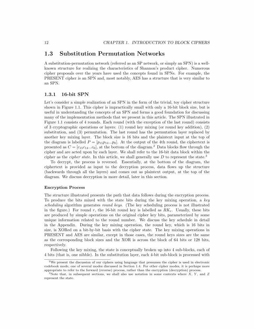
Let’s consider a simple realization of an SPN in the form of the trivial, toy cipher structureshown in Figure 1.1. This cipher is impractically small with only a 16-bit block size, but isuseful in understanding the concepts of an SPN and forms a good foundation for discussingmany of the implementation methods that we present in this article. The SPN illustrated inFigure 1.1 consists of 4 rounds. Each round (with the exception of the last round) consistsof 3 cryptographic operations or layers: (1) round key mixing (or round key addition), (2)substitution, and (3) permutation. The last round has the permutation layer replaced byanother key mixing layer. The block size is 16 bits and the plaintext input at the top ofthe diagram is labelled P = [p15p14...p0]. At the output of the 4th round, the ciphertext ispresented as C = [c15c14...c0], at the bottom of the diagram.2 Data blocks flow through thecipher and are acted upon by each layer. We shall refer to the 16-bit data block within thecipher as the cipher state. In this article, we shall generally use D to represent the state.3
To decrypt, the process is reversed. Essentially, at the bottom of the diagram, theciphertext is provided as input to the decryption process, data flows up the structure(backwards through all the layers) and comes out as plaintext output, at the top of thediagram. We discuss decryption in more detail, later in this section.
Encryption Process
The structure illustrated presents the path that data follows during the encryption process.To produce the bits mixed with the state bits during the key mixing operation, a keyscheduling algorithm generates round keys. (The key scheduling process is not illustratedin the figure.) For round r, the 16-bit round key is labelled as RKr. Usually, these bitsare produced by simple operations on the original cipher key bits, parameterized by someunique information related to the round number. We discuss the key schedule in detailin the Appendix. During the key mixing operation, the round key, which is 16 bits insize, is XORed on a bit-by-bit basis with the cipher state. The key mixing operations inPRESENT and AES are similar, except in those cases, the round keys sizes are the sameas the corresponding block sizes and the XOR is across the block of 64 bits or 128 bits,respectively.
Following the key mixing, the state is conceptually broken up into 4 sub-blocks, each of4 bits (that is, one nibble). In the substitution layer, each 4-bit sub-block is processed with
2We present the discussion of our ciphers using language that presumes the cipher is used in electroniccodebook mode, one of several modes discussed in Section 1.4. For other cipher modes, it is perhaps moreappropriate to refer to the forward (reverse) process, rather than the encryption (decryption) process.
3Note that, in subsequent sections, we shall also use notation in some contexts where X, Y , and Zrepresent the state.

1.3. SUBSTITUTION PERMUTATION NETWORKS 13
roundkeyRK1mixing
roundkeyRK2mixing
roundkeyRK3mixing
roundkeyRK4mixing
roundkeyRK5mixing
keymixing
permutation
substitution
plaintext
...c0
...p0p15...
round1
round2
round3
round4
c15... ciphertext
S1 S2 S3 S4
S1 S2 S3 S4
S1 S2 S3 S4
S1 S2 S3 S4
Figure 1.1: 16-bit SPN (4 Rounds)
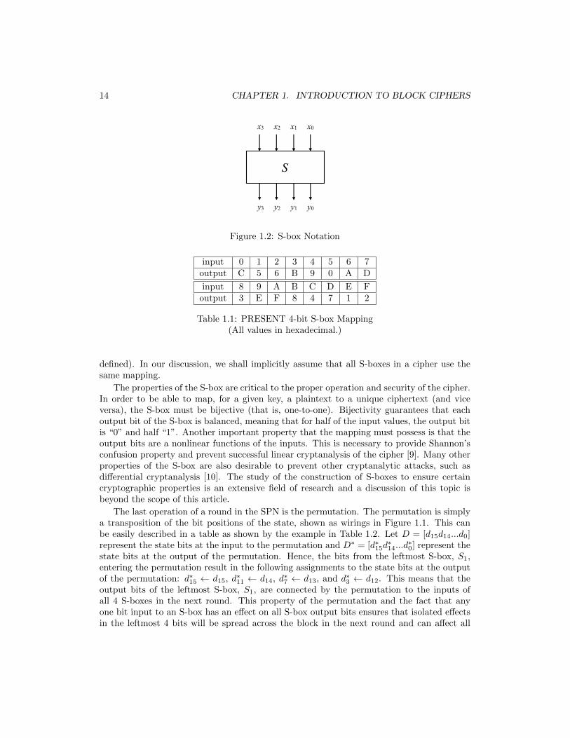
a substitution box or S-box. A 4-bit S-box takes a 4-bit input and maps it to a 4-bit outputas shown in Figure 1.2. The 4-bit S-box operation can be thought of as a table lookup (andcan be implemented as such) where the table consists of 24 nibbles. The input is used as anindex into the table and the output is selected from the position pointed to by the index.An S-box is a fixed mapping (i.e., it is not key dependent) and an example of a 4-bit S-boxis shown in Table 1.1. This is the S-box found in the PRESENT cipher [6]. PRESENT isan SPN and, as with many lightweight ciphers, it uses a small S-box mapping. In contrast,AES uses an 8-bit S-box which is represented by a table of 28 8-bit values, indexed by the8-bit input. In the substitution layer, it is conceivable that all S-boxes are defined to bedifferent mappings (this was the case, for example, with the Data Encryption Standard [8]),but it is more typical for ciphers to use only one mapping for all S-boxes. This is the casefor the PRESENT cipher (with one 4-bit S-box defined) and AES (with one 8-bit S-box
14 CHAPTER 1. INTRODUCTION TO BLOCK CIPHERS
x3 x2 x1 x0
S
y3 y2 y1 y0
Figure 1.2: S-box Notation
input 0 1 2 3 4 5 6 7output C 5 6 B 9 0 A D
input 8 9 A B C D E Foutput 3 E F 8 4 7 1 2
Table 1.1: PRESENT 4-bit S-box Mapping(All values in hexadecimal.)
defined). In our discussion, we shall implicitly assume that all S-boxes in a cipher use thesame mapping.
The properties of the S-box are critical to the proper operation and security of the cipher.In order to be able to map, for a given key, a plaintext to a unique ciphertext (and viceversa), the S-box must be bijective (that is, one-to-one). Bijectivity guarantees that eachoutput bit of the S-box is balanced, meaning that for half of the input values, the output bitis “0” and half “1”. Another important property that the mapping must possess is that theoutput bits are a nonlinear functions of the inputs. This is necessary to provide Shannon’sconfusion property and prevent successful linear cryptanalysis of the cipher [9]. Many otherproperties of the S-box are also desirable to prevent other cryptanalytic attacks, such asdifferential cryptanalysis [10]. The study of the construction of S-boxes to ensure certaincryptographic properties is an extensive field of research and a discussion of this topic isbeyond the scope of this article.
The last operation of a round in the SPN is the permutation. The permutation is simplya transposition of the bit positions of the state, shown as wirings in Figure 1.1. This canbe easily described in a table as shown by the example in Table 1.2. Let D = [d15d14...d0]represent the state bits at the input to the permutation and D∗ = [d∗15d
∗14...d
∗0] represent the
state bits at the output of the permutation. Hence, the bits from the leftmost S-box, S1,entering the permutation result in the following assignments to the state bits at the outputof the permutation: d∗15 ← d15, d∗11 ← d14, d∗7 ← d13, and d∗3 ← d12. This means that theoutput bits of the leftmost S-box, S1, are connected by the permutation to the inputs ofall 4 S-boxes in the next round. This property of the permutation and the fact that anyone bit input to an S-box has an effect on all S-box output bits ensures that isolated effectsin the leftmost 4 bits will be spread across the block in the next round and can affect all
1.3. SUBSTITUTION PERMUTATION NETWORKS 15
input 15 14 13 12 11 10 9 8output 15 11 7 3 14 10 6 2
input 7 6 5 4 3 2 1 0output 13 9 5 1 12 8 4 0
Table 1.2: 16-bit Permutation(Bit 15 is leftmost bit.)
Operation Input Output Comment
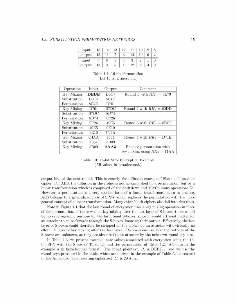
Key Mixing DEBE B0C7 Round 1 with RK1 = 6E79Substitution B0C7 8C4DPermutation 8C4D D701Key Mixing D701 B7DC Round 2 with RK2 = 60DDSubstitution B7DC 8D74Permutation 8D74 C726Key Mixing C726 49E5 Round 3 with RK3 = 8EC3Substitution 49E5 9E10Permutation 9E10 C44AKey Mixing C4AA 1354 Round 4 with RK4 = D71ESubstitution 1354 5B09Key Mixing 5B09 2AA3 Replace permutation with
key mixing using RK5 = 71AA
Table 1.3: 16-bit SPN Encryption Example(All values in hexadecimal.)
output bits of the next round. This is exactly the diffusion concept of Shannon’s productcipher. For AES, the diffusion in the cipher is not accomplished by a permutation, but by alinear transformation which is comprised of the ShiftRows and MixColumns operations [2].However, a permutation is a very specific form of a linear transformation, so in a sense,AES belongs to a generalized class of SPNs, which replaces the permutation with the moregeneral concept of a linear transformation. Many other block ciphers also fall into this class.
Note in Figure 1.1 that the last round of encryption uses a key mixing operation in placeof the permutation. If there was no key mixing after the last layer of S-boxes, there wouldbe no cryptographic purpose for the last round S-boxes, since it would a trivial matter foran attacker to go backwards through the S-boxes, knowing their output. Effectively, the lastlayer of S-boxes could therefore be stripped off the cipher by an attacker with virtually noeffort. A layer of key mixing after the last layer of S-boxes ensures that the outputs of theS-boxes are unknown, as they are obscured to an attacker by the unknown round key bits.
In Table 1.3, we present example state values associated with encryption using the 16-bit SPN with the S-box of Table 1.1 and the permutation of Table 1.2. All data in theexample is in hexadecimal format. The input plaintext, P , is DEBE16, and we use theround keys presented in the table, which are derived in the example of Table A.1 discussedin the Appendix. The resulting ciphertext, C, is 2AA316.

16 CHAPTER 1. INTRODUCTION TO BLOCK CIPHERS
input 0 1 2 3 4 5 6 7output 5 E F 8 C 1 2 D
input 8 9 A B C D E Foutput B 4 6 3 0 7 9 A
Table 1.4: 4-bit Inverse S-box(All values in hexadecimal.)
Decryption Process
As mentioned, decryption involves going backwards through the network. This has 3implications:
1. decryption uses the inverse of the components used for encryption,
2. the round keys used in decryption are the same as for encryption but applied in reverseorder, and
3. with the adjustment of round key bit positions, decryption can be viewed as similar instructure to encryption.
Consider the 3 layers and their inverses. The XOR function of the key mixing is triviallyreversed. Assume input state bit d is XORed with round key bit rk to produce a new statebit, d∗: d∗ = d ⊕ rk. The inverse of this operation produces output d given input d∗ andthis is trivially possible using the operation d = d∗ ⊕ rk based on the properties of XOR.The inverse S-box is easily derived by reversing the roles of input and output. Hence, for anS-box which maps input 00112 (316) to output 10112 (B16), the inverse S-box maps input10112 (B16) to output 00112 (316). Hence, the S-box defined by Table 1.1 has the inverseS-box given in Table 1.4. Finally, the permutation is obviously easily invertible by reversingthe wiring associated with the permutation. For example, input bit 4 leads to output bit 1,implying for the inverse permutation, input bit 1 leads to output bit 4. For the permutationof Table 1.2, the inverse permutation is identical to the permutation.
It is clear that, since decryption is equivalent to processing from the bottom of Figure 1.1to the top, the round key RK5 must be applied first and round key RK1 last in decryption.Hence, it is necessary to run through the complete key schedule to derive the last roundkey before decrypting any ciphertext. In suitable environments where the required memoryis available, the round keys can be stored during this process and then used later duringdecryption. However, for many environments, particularly for hardware implementations, itis not possible to store all round keys and instead the key schedule will need to be run inreverse from the last round key, concurrently with the processing in the decryption datapath.
Lastly, decryption can be restructured to look like encryption, which could be importantto some implementations where similar structures between encryption and decryption mightlead to efficient, easily understood designs. Going backwards through Figure 1.1, we cansee that we process a key mixing of RK5 and (inverse) substitution first, then follow witha key mixing of RK4 after which the (inverse) permutation is applied. But if we take thebits of RK4 and reorder them based on the inverse permutation, we can perform the inversepermutation before the key mixing and follow the inverse permutation with a key mixing

1.3. SUBSTITUTION PERMUTATION NETWORKS 17
!!!!!
!
Figure 1.3: 64-bit SPN (3 rounds)
with the reordered RK4. Similarly, we can reorder RK3 and RK2 and apply them afterthe inverse permutation in the decryption process. In doing this, we have the same order ofcryptographic layers in the decryption process as in the encryption process.
1.3.2 64-bit SPN
In the previous section, we presented and discussed the components in a toy 16-bit cipher.While the block size of this cipher is not at all practical, the components described, includingthe 4-bit S-box are realistic and ciphers with larger block sizes exist which are similarin structure. In this section, we present a realistically-sized 64-bit SPN block cipher.This cipher structure is, in fact, equivalent the structure of the PRESENT cipher [6].PRESENT is an important, foundational cipher in the area of lightweight cryptographyand is a recommended ISO standard [11].
The architecture of the 64-bit SPN consisting of 3 rounds is given in Figure 1.3. Thefigure illustrates the placement of the key mixing layer, but does not show the key scheduling

18 CHAPTER 1. INTRODUCTION TO BLOCK CIPHERS
input 63 62 61 60 59 58 57 56output 63 47 31 15 62 46 30 14
input 55 54 53 52 51 50 49 48output 61 45 29 13 60 44 28 12
input 47 46 45 44 43 42 41 40output 59 43 27 11 58 42 26 10
input 39 38 37 36 35 34 33 32output 57 41 25 9 56 40 24 8
input 31 30 29 28 27 26 25 24output 55 39 23 7 54 38 22 6
input 23 22 21 20 19 18 17 16output 53 37 21 5 52 36 20 4
input 15 14 13 12 11 10 9 8output 51 35 19 3 50 34 18 2
input 7 6 5 4 3 2 1 0output 49 33 17 1 48 32 16 0
Table 1.5: 64-bit Permutation(Bit 63 is leftmost bit.)
algorithm which generates the round keys to mix. Although the block size and potential keysize for this cipher are practical, such a cipher with only 3 rounds would not be secure andwould be susceptible to many cryptanalytic attacks. Decryption would be accomplished byeffectively going backwards (bottom to top) through the structure shown. The PRESENTcipher, while similar in structure, consists of 31 rounds, chosen to ensure security for an80-bit or 128-bit key.
For PRESENT, one mapping is used for all S-boxes and it is given by the mappingpresented in Table 1.1. The permutation illustrated in the figure is summarized in Table 1.5.The key mixing uses bit-by-bit XOR, which in this case is done across the 64-bit state andmakes use of a 64-bit round key generated using a key schedule applied to the full cipherkey (which is either 80-bits or 128-bits for PRESENT).
1.4 Modes of Operation
In order to efficiently and securely use a block cipher, one must use the cipher in anappropriate mode of operation. There are many different modes that have been defined withdifferent objectives in mind. Fundamentally a mode must be secure and must provide thecharacteristics of significance for the targeted application. The mode employed can have animportant impact on the implementation selected. Alternatively, the desired implementationstructure (based on the application requirements) can impact the selected mode. We brieflydescribe three well-known modes [12], but note that many more are proposed and appliedin practice.

1.4. MODES OF OPERATION 19
cipher key K
ciphertext Ci
enc
plaintext Pi
(a) Encryption
cipher key K
plaintext Pi
dec
ciphertext Ci
(b) Decryption
Figure 1.4: Electronic CodeBook Mode
1.4.1 Electronic CodeBook Mode
Electronic CodeBook (ECB) mode is likely the natural mode one thinks about for blockciphers. To encrypt the i-th block of plaintext, one applies the block to the input of theblock cipher and, using the cipher key as a parameter, produces the i-th block of ciphertextat the output. This is illustrated in Figure 1.4. Note that Figures 1.1 and 1.3 have theirinputs and outputs labelled with the presumption that they are used in ECB mode. Thatis, the input to the block cipher operation is the plaintext and the output is the ciphertext.As we shall see, this is not the case for other modes.
In practice, it is not generally advisable to use ECB for the encryption of large amounts ofdata, because it is not considered to be semantically secure (that is, it is possible to determinesome information about the plaintext by observing ciphertext). Consider, for example, thata known plaintext block Pi is encrypted in ECB mode using a particular key to produce theknown observed ciphertext block Ci. If we later observe a second ciphertext Cj (producedusing the same key), such that Cj = Ci, we can then determine that the plaintext Pj used toproduce Cj must be the same as Pi, that is, Pj = Pi. This is a potentially significant sourceof leakage of plaintext information based on observing the ciphertext and having knowledgeof some plaintext/ciphertext pairs and could be a serious problem if large amounts of dataare encrypted. ECB mode can be useful for encrypting small amounts of random data,such as might be the case when protecting keys by encrypting them so that they can betransferred confidentially between parties.
Note that, generally, our discussion in this article is presented using language whichimplies the use of ECB mode. However, the implementation methods can be clearly translatedinto other modes as appropriate and we do provide some discussion on the suitability ofimplementations for different modes.

20 CHAPTER 1. INTRODUCTION TO BLOCK CIPHERS
ciphertext Ci-1
plaintext Pi ciphertext Ci
cipher key K cipher key K
ciphertext Ci-1
enc
ciphertext Ci
(a) Encryption
dec
plaintext Pi
(b) Decryption
Figure 1.5: Cipher Block Chaining Mode
1.4.2 Cipher Block Chaining Mode
Cipher Block Chaining (CBC) is a mode of operation which can be effectively used to encryptlarge amounts of data using a block cipher without the semantic security issues associatedwith ECB mode. Encryption and decryption using CBC mode is illustrated in Figure 1.5.To encrypt the i-th block in a sequence of many plaintext blocks, CBC mode would XORthe plaintext block, Pi, with the ciphertext produced for the previous block, Ci−1. Theresulting block is then fed to the input of the block cipher (operating as an encryptionprocess) with the resulting output considered to be the ciphertext Ci. The first plaintextblock, P1, uses an initialization vector (IV) as C0, since no ciphertext block yet exists.Decryption in CBC mode takes the ciphertext, Ci, as input to the block cipher (operatingas a decryption process), from which the plaintext Pi is derived following XOR of the resultwith the previous ciphertext block, Ci−1.
The chaining aspect ensures that the encryption of a block is dependent on the encryptionresults from previous ciphertexts, thereby preventing the problem of ECB mode wheretwo identical plaintext blocks result in identical ciphertext blocks. In typical encryptionapplications, the IV should be a nonce, which is a variable only assigned any value once.Hence, for CBC mode, different sessions will start the chain using IVs which should beunique to avoid semantic security issues with the first block. However, in many applicationsit is not necessary to keep IVs secret. CBC can be used as a general method to encryptlarge amounts of data, consisting of many plaintext blocks and can be found applied in manycontexts.
1.4.3 Counter Mode
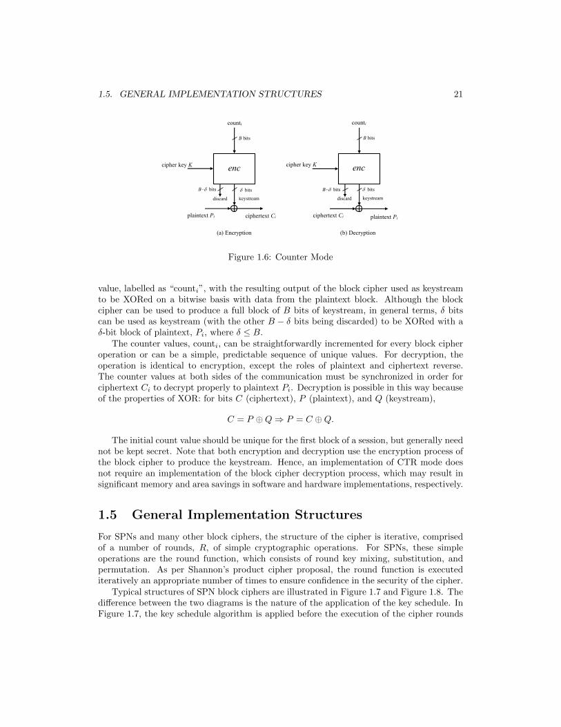
Counter (CTR) mode is another block cipher mode of operation suitable for encrypting alarge amount of plaintext data. In CTR mode, the block cipher is configured to operate asa stream cipher, which produces ciphertext bits by XORing plaintext bits with keystreambits. In CTR mode, illustrated in Figure 1.6, the block cipher takes as input a B-bit counter
1.5. GENERAL IMPLEMENTATION STRUCTURES 21
B-d bits d bits
keystream keystream
cipher key K
ciphertext Ci plaintext Pi
(a) Encryption (b) Decryption
B bits
B-d bits d bits
discard
plaintext Pi
cipher key K
counti
enc
ciphertext Ci
B bits
discard
counti
enc
Figure 1.6: Counter Mode
value, labelled as “counti”, with the resulting output of the block cipher used as keystreamto be XORed on a bitwise basis with data from the plaintext block. Although the blockcipher can be used to produce a full block of B bits of keystream, in general terms, δ bitscan be used as keystream (with the other B − δ bits being discarded) to be XORed with aδ-bit block of plaintext, Pi, where δ ≤ B.
The counter values, counti, can be straightforwardly incremented for every block cipheroperation or can be a simple, predictable sequence of unique values. For decryption, theoperation is identical to encryption, except the roles of plaintext and ciphertext reverse.The counter values at both sides of the communication must be synchronized in order forciphertext Ci to decrypt properly to plaintext Pi. Decryption is possible in this way becauseof the properties of XOR: for bits C (ciphertext), P (plaintext), and Q (keystream),
C = P ⊕Q⇒ P = C ⊕Q.
The initial count value should be unique for the first block of a session, but generally neednot be kept secret. Note that both encryption and decryption use the encryption process ofthe block cipher to produce the keystream. Hence, an implementation of CTR mode doesnot require an implementation of the block cipher decryption process, which may result insignificant memory and area savings in software and hardware implementations, respectively.
1.5 General Implementation Structures
For SPNs and many other block ciphers, the structure of the cipher is iterative, comprisedof a number of rounds, R, of simple cryptographic operations. For SPNs, these simpleoperations are the round function, which consists of round key mixing, substitution, andpermutation. As per Shannon’s product cipher proposal, the round function is executediteratively an appropriate number of times to ensure confidence in the security of the cipher.
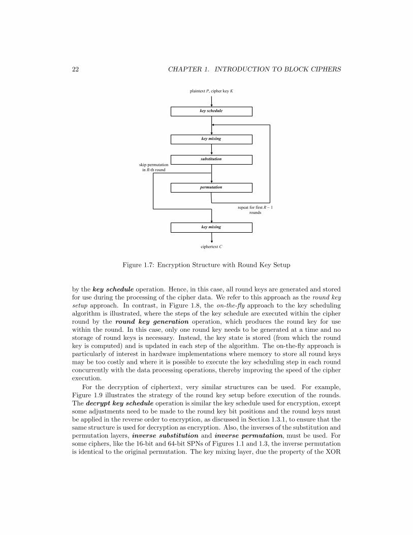
Typical structures of SPN block ciphers are illustrated in Figure 1.7 and Figure 1.8. Thedifference between the two diagrams is the nature of the application of the key schedule. InFigure 1.7, the key schedule algorithm is applied before the execution of the cipher rounds
22 CHAPTER 1. INTRODUCTION TO BLOCK CIPHERS
skip permutation in R-th round
repeat for first R - 1 rounds
key schedule
key mixing
plaintext P, cipher key K
substitution
permutation
key mixing
ciphertext C
Figure 1.7: Encryption Structure with Round Key Setup
by the key schedule operation. Hence, in this case, all round keys are generated and storedfor use during the processing of the cipher data. We refer to this approach as the round keysetup approach. In contrast, in Figure 1.8, the on-the-fly approach to the key schedulingalgorithm is illustrated, where the steps of the key schedule are executed within the cipherround by the round key generation operation, which produces the round key for usewithin the round. In this case, only one round key needs to be generated at a time and nostorage of round keys is necessary. Instead, the key state is stored (from which the roundkey is computed) and is updated in each step of the algorithm. The on-the-fly approach isparticularly of interest in hardware implementations where memory to store all round keysmay be too costly and where it is possible to execute the key scheduling step in each roundconcurrently with the data processing operations, thereby improving the speed of the cipherexecution.
For the decryption of ciphertext, very similar structures can be used. For example,Figure 1.9 illustrates the strategy of the round key setup before execution of the rounds.The decrypt key schedule operation is similar the key schedule used for encryption, exceptsome adjustments need to be made to the round key bit positions and the round keys mustbe applied in the reverse order to encryption, as discussed in Section 1.3.1, to ensure that thesame structure is used for decryption as encryption. Also, the inverses of the substitution andpermutation layers, inverse substitution and inverse permutation, must be used. Forsome ciphers, like the 16-bit and 64-bit SPNs of Figures 1.1 and 1.3, the inverse permutationis identical to the original permutation. The key mixing layer, due the property of the XOR

1.6. SUMMARY 23
skip permutation in R-th round
repeat for first R - 1 rounds
round key generation
key mixing
plaintext P, cipher key K
substitution
permutation
key mixing
ciphertext C
round key generation
Figure 1.8: Encryption Structure with On-the-Fly Round Key Generation
function, is the same for decryption as for encryption.
We use these two general structures of (1) round key setup and (2) on-the-fly round keygeneration as the basis for our discussions of the implementation of ciphers in software andhardware.
1.6 Summary
In this chapter, we have presented the basic notions associated with block ciphers. Specifically,we have described the concept of the substitution-permutation network, one of the basicarchitectures used to implement block ciphers. We have presented concrete examples of atoy 16-bit SPN and a practical 64-bit SPN. The 64-bit SPN is, in fact, the same architectureas the lightweight cipher, PRESENT. We have also given the S-box from PRESENT as an

24 CHAPTER 1. INTRODUCTION TO BLOCK CIPHERS
skip permutation in R-th round
repeat for first R - 1 rounds
decrypt key schedule
key mixing
ciphertext C, cipher key K
inverse substitution
inverse permutation
key mixing
plaintext P
Figure 1.9: Decryption Structure with Round Key Setup
example component used in the cipher.This chapter has also introduced the notion of the mode of operation of a block cipher
and we shall see that often the mode applied to a cipher influences the selection of theimplementation method (and possibly vice versa). Finally, we have illustrated the generaliterative structure of the SPN and discussed how the key schedule can be implemented ineither a setup phase or on-the-fly during the processing of the cipher rounds.
In the next chapter, we will delve into the practical implementation of block ciphers byconsidering the software implementation of the SPN focusing on general methodologies suchas table lookups and bit-slicing structures.

Chapter 2
Software Implementation
In this chapter, we outline some of the principles and methods with which a designer couldimplement a block cipher in software. We focus on general concepts and do not delveinto presenting any specific coding examples. Instead, we use pseudocode, descriptions,and examples to illustrate concepts. In doing so, we presume the availability of typicalinstructions that are found in all processors and refrain from discussing implementation issuesrelated to specific processor instructions which might be helpful in cipher implementationbut which are not ubiquitously found in computing environments.
2.1 Structure of Encryption
Since block ciphers, such as SPNs, are iterative in structure, they can be easily structured ina software program using “for” loops as shown in the pseudocode presented in Algorithm 1,where D is used to represent the cipher state. In the pseudocode, the round key setupapproach is used for key scheduling so that round key values are generated prior to theprocessing of the plaintext data. This is done by calling KEYSCHED which produces andstores the data for the round key array, [RK1, RK2, ..., RKR, RKR+1], based on the initialcipher key. This pseudocode is analogous the structure of Figure 1.7.
The pseudocode developed from the structure of Figure 1.8, with on-the-fly round keygeneration, is given in Algorithm 2. Here the steps of the key scheduling algorithm areplaced within the body of the loop by calling function ROUNDKEY GENERATE. Hence, it isnot necessary to store the complete set of round keys but to just produce the round keyrequired for the current round based on the key state.
For an R round cipher, the body of the loop in both Algorithm 1 and Algorithm 2performs the round operations and the loop is iterated R − 1 times, with the R-th round(which replaces the permutation with a key mixing) following the loop. In software, thefunctions KEYMIX, SUBSTITUTION, and PERMUTATION can be implemented using variousmethods, with the method selected based on an objective associated with the implementation,such as maximizing speed or minimizing storage. The implementation of these operationswill be discussed in upcoming sections.
The key setup strategy of Algorithm 1 could be used when high speeds for software
25

26 CHAPTER 2. SOFTWARE IMPLEMENTATION
Algorithm 1 Pseudocode for Encryption with Round Key Setup
function encrypt(P,K) . inputs: plaintext P and cipher key K[RK1, RK2, ..., RKR, RKR+1]← keysched(K) . generate round keysD ← P . load P into cipher state Dfor r = 1 to R− 1 do
D ← keymix(D,RKr)D ← substitution(D)D ← permutation(D)
end forD ← keymix(D,RKR)D ← substitution(D)D ← keymix(D,RKR+1) . last round replaces permutation with key mixingreturn D . output: ciphertext C
end function
implementations are required, since the key schedule algorithm only needs to be executedonce, before the encryption of all plaintexts to be encrypted under the key. The tradeoff isthat all round keys must be stored for use, which requires more memory and this may bean issue in a tightly constrained system such as those found in some IoT devices. Using theon-the-fly key scheduling strategy of Algorithm 2 will be clearly slower in software, sinceextra operations in ROUNDKEY GENERATE must be executed for every pass of the loop forencryption of every plaintext. However, in this case, it is not necessary to store the fullset of round keys and, hence, there may be advantages in environments with tight memoryconstraints but where speed of the encryption process is not an issue.
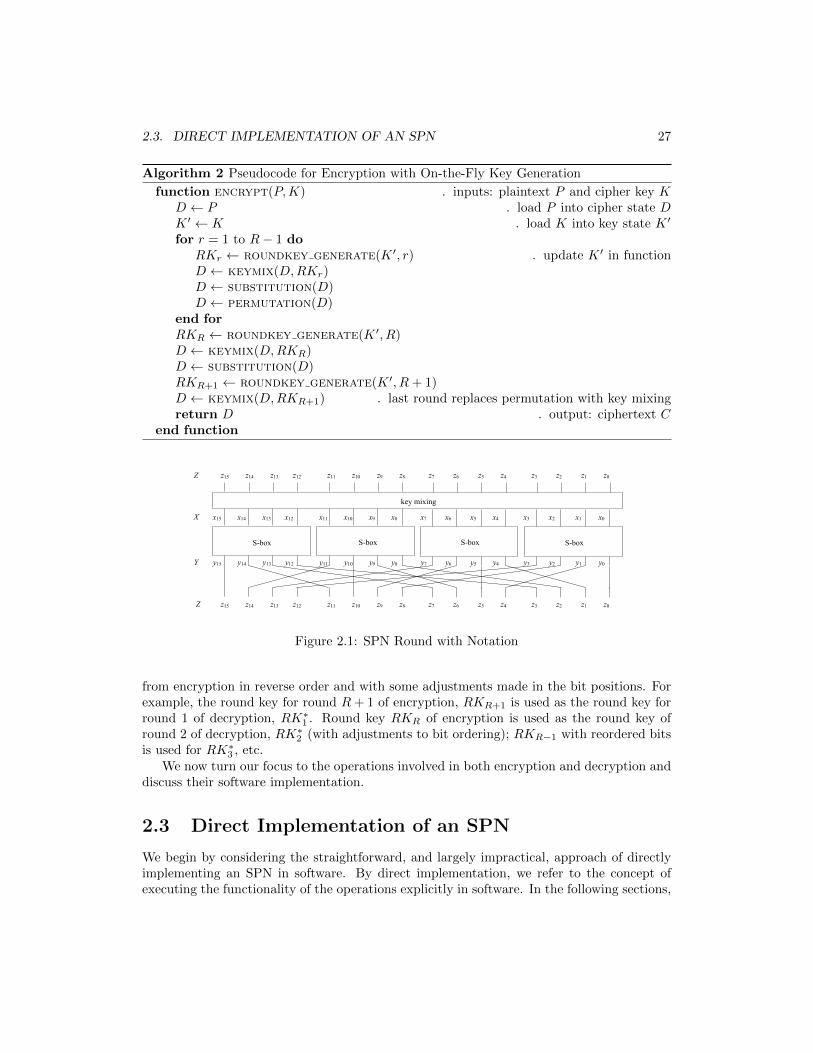
In subsequent sections, we discuss detailed characteristics of various implementationmethods for the operations - key mixing, substitution, and permutation - within the roundfunction. Although we have referred to the cipher state as D in the pseudocode describedin this section, for convenience, in our description of the layers, we shall often use differentvariables to represent the state based on which layer is taking the state as input or producingthe state as output. In particular, we shall use the following labels. The state at the inputof the substitution (and output of the key mixing), we shall label as X = [xB−1xB−2...x0].The state at the output of the substitution and input to the permutation is labelled asY = [yB−1yB−2...y0], while the state at the output of the permutation (and input of the keymixing) shall be referred to as Z = [zB−1zB−2...z0]. For clarity, this is illustrated for oneround of the 16-bit SPN in Figure 2.1.
2.2 Structure of Decryption
One of the advantages of the SPN architecture is that the decryption process is similar instructure to encryption and this is illustrated in Figure 1.9.
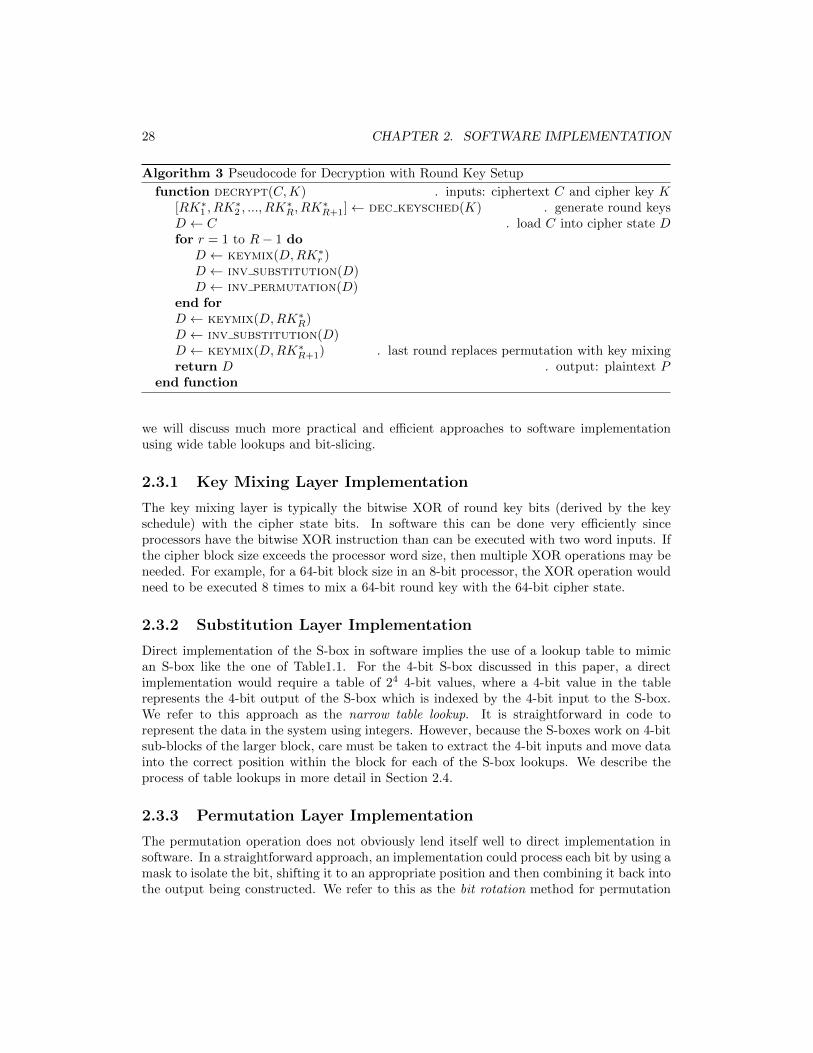
In Algorithm 3, we present the pseudocode for the decryption process and it can be seenthat the layers use inverse operations (specifically the S-box and permutation operationsINV SUBSTITUTION and INV PERMUTATION) as appropriate. Also notably, the round keysfor the decryption process, represented as RK∗r , require the application of the round keys
2.3. DIRECT IMPLEMENTATION OF AN SPN 27
Algorithm 2 Pseudocode for Encryption with On-the-Fly Key Generation
function encrypt(P,K) . inputs: plaintext P and cipher key KD ← P . load P into cipher state DK ′ ← K . load K into key state K ′
for r = 1 to R− 1 doRKr ← roundkey generate(K ′, r) . update K ′ in functionD ← keymix(D,RKr)D ← substitution(D)D ← permutation(D)
end forRKR ← roundkey generate(K ′, R)D ← keymix(D,RKR)D ← substitution(D)RKR+1 ← roundkey generate(K ′, R+ 1)D ← keymix(D,RKR+1) . last round replaces permutation with key mixingreturn D . output: ciphertext C
end function
z15 z14 z13 z12 z11 z10 z9 z8 z3 z2 z1 z0 z7 z6 z5 z4
y15 y14 y13 y12 y11 y10 y9 y8 y3 y2 y1 y0 y7 y6 y5 y4
x15 x14 x13 x12 x11 x10 x9 x8 x3 x2 x1 x0 x7 x6 x5 x4
key mixing
S-box S-box S-box S-box
z15 z14 z13 z12 z11 z10 z9 z8 z3 z2 z1 z0 z7 z6 z5 z4 Z
X
Y
Z
Figure 2.1: SPN Round with Notation
from encryption in reverse order and with some adjustments made in the bit positions. Forexample, the round key for round R+ 1 of encryption, RKR+1 is used as the round key forround 1 of decryption, RK∗1 . Round key RKR of encryption is used as the round key ofround 2 of decryption, RK∗2 (with adjustments to bit ordering); RKR−1 with reordered bitsis used for RK∗3 , etc.
We now turn our focus to the operations involved in both encryption and decryption anddiscuss their software implementation.
2.3 Direct Implementation of an SPN
We begin by considering the straightforward, and largely impractical, approach of directlyimplementing an SPN in software. By direct implementation, we refer to the concept ofexecuting the functionality of the operations explicitly in software. In the following sections,
28 CHAPTER 2. SOFTWARE IMPLEMENTATION
Algorithm 3 Pseudocode for Decryption with Round Key Setup
function decrypt(C,K) . inputs: ciphertext C and cipher key K[RK∗1 , RK
∗2 , ..., RK
∗R, RK
∗R+1]← dec keysched(K) . generate round keys
D ← C . load C into cipher state Dfor r = 1 to R− 1 do
D ← keymix(D,RK∗r )D ← inv substitution(D)D ← inv permutation(D)
end forD ← keymix(D,RK∗R)D ← inv substitution(D)D ← keymix(D,RK∗R+1) . last round replaces permutation with key mixingreturn D . output: plaintext P
end function
we will discuss much more practical and efficient approaches to software implementationusing wide table lookups and bit-slicing.
2.3.1 Key Mixing Layer Implementation
The key mixing layer is typically the bitwise XOR of round key bits (derived by the keyschedule) with the cipher state bits. In software this can be done very efficiently sinceprocessors have the bitwise XOR instruction than can be executed with two word inputs. Ifthe cipher block size exceeds the processor word size, then multiple XOR operations may beneeded. For example, for a 64-bit block size in an 8-bit processor, the XOR operation wouldneed to be executed 8 times to mix a 64-bit round key with the 64-bit cipher state.
2.3.2 Substitution Layer Implementation
Direct implementation of the S-box in software implies the use of a lookup table to mimican S-box like the one of Table1.1. For the 4-bit S-box discussed in this paper, a directimplementation would require a table of 24 4-bit values, where a 4-bit value in the tablerepresents the 4-bit output of the S-box which is indexed by the 4-bit input to the S-box.We refer to this approach as the narrow table lookup. It is straightforward in code torepresent the data in the system using integers. However, because the S-boxes work on 4-bitsub-blocks of the larger block, care must be taken to extract the 4-bit inputs and move datainto the correct position within the block for each of the S-box lookups. We describe theprocess of table lookups in more detail in Section 2.4.
2.3.3 Permutation Layer Implementation
The permutation operation does not obviously lend itself well to direct implementation insoftware. In a straightforward approach, an implementation could process each bit by using amask to isolate the bit, shifting it to an appropriate position and then combining it back intothe output being constructed. We refer to this as the bit rotation method for permutation
2.4. TABLE LOOKUP IMPLEMENTATIONS 29
implementation. For example, consider the leftmost 2 bits entering the 16-bit permutation ofTable 1.2. Assume the input to the permutation is the 16-bit state Y and the 16-bit outputstate is Z. The two bits, y15 and y14, are assigned to outputs as follows: z15 ← y15 andz11 ← y14. This can be done by initializing Z to all zeroes. Then, assign Y to a temporary16-bit variable of the state, W , and mask the leftmost bit by ANDing W with 800016.XOR the result with Z to produce Z = [y1500...00]. Next, assign Y again to W , mask thesecond bit using 400016, shift 3 bits to the right to generate W = [0000y140...00], whichwhen XORed with Z produces Z = [y15000y14...00].1 This can be repeated to move, veryinefficiently, all 16 bits of the state, according to the permutation. The bit rotation methodis generally a poor choice to implement the permutation, although some modern processorshave data manipulation instructions that may allow an improvement in the efficiency of theapproach.
2.4 Table Lookup Implementations
In order to improve the efficiency of the software implementation of an SPN, one could makemuch more extensive use of table lookups. As we discussed in the previous section, S-boxesare naturally implemented as table lookups and, in this section, we will discuss how they canbe conveniently combined with a lookup for the permutation. The other layer in a round,key mixing, is efficiently done using bitwise XOR on data blocks and does not need to involvetable operations.
2.4.1 Permutation in a Table
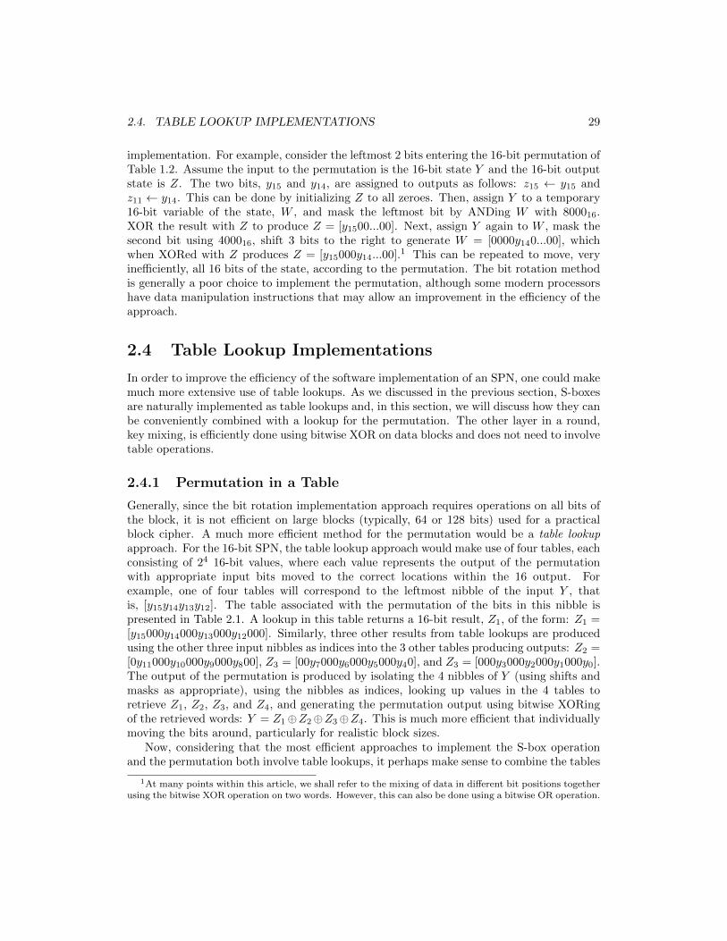
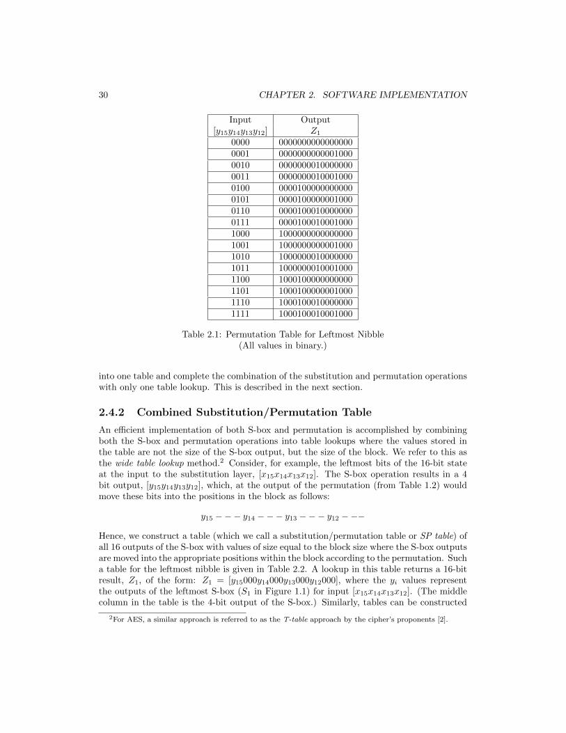
Generally, since the bit rotation implementation approach requires operations on all bits ofthe block, it is not efficient on large blocks (typically, 64 or 128 bits) used for a practicalblock cipher. A much more efficient method for the permutation would be a table lookupapproach. For the 16-bit SPN, the table lookup approach would make use of four tables, eachconsisting of 24 16-bit values, where each value represents the output of the permutationwith appropriate input bits moved to the correct locations within the 16 output. Forexample, one of four tables will correspond to the leftmost nibble of the input Y , thatis, [y15y14y13y12]. The table associated with the permutation of the bits in this nibble ispresented in Table 2.1. A lookup in this table returns a 16-bit result, Z1, of the form: Z1 =[y15000y14000y13000y12000]. Similarly, three other results from table lookups are producedusing the other three input nibbles as indices into the 3 other tables producing outputs: Z2 =[0y11000y10000y9000y800], Z3 = [00y7000y6000y5000y40], and Z3 = [000y3000y2000y1000y0].The output of the permutation is produced by isolating the 4 nibbles of Y (using shifts andmasks as appropriate), using the nibbles as indices, looking up values in the 4 tables toretrieve Z1, Z2, Z3, and Z4, and generating the permutation output using bitwise XORingof the retrieved words: Y = Z1⊕Z2⊕Z3⊕Z4. This is much more efficient that individuallymoving the bits around, particularly for realistic block sizes.
Now, considering that the most efficient approaches to implement the S-box operationand the permutation both involve table lookups, it perhaps make sense to combine the tables
1At many points within this article, we shall refer to the mixing of data in different bit positions togetherusing the bitwise XOR operation on two words. However, this can also be done using a bitwise OR operation.
30 CHAPTER 2. SOFTWARE IMPLEMENTATION
Input Output[y15y14y13y12] Z1
0000 00000000000000000001 00000000000010000010 00000000100000000011 00000000100010000100 00001000000000000101 00001000000010000110 00001000100000000111 00001000100010001000 10000000000000001001 10000000000010001010 10000000100000001011 10000000100010001100 10001000000000001101 10001000000010001110 10001000100000001111 1000100010001000
Table 2.1: Permutation Table for Leftmost Nibble(All values in binary.)
into one table and complete the combination of the substitution and permutation operationswith only one table lookup. This is described in the next section.
2.4.2 Combined Substitution/Permutation Table
An efficient implementation of both S-box and permutation is accomplished by combiningboth the S-box and permutation operations into table lookups where the values stored inthe table are not the size of the S-box output, but the size of the block. We refer to this asthe wide table lookup method.2 Consider, for example, the leftmost bits of the 16-bit stateat the input to the substitution layer, [x15x14x13x12]. The S-box operation results in a 4bit output, [y15y14y13y12], which, at the output of the permutation (from Table 1.2) wouldmove these bits into the positions in the block as follows:
y15 −−− y14 −−− y13 −−− y12 −−−
Hence, we construct a table (which we call a substitution/permutation table or SP table) ofall 16 outputs of the S-box with values of size equal to the block size where the S-box outputsare moved into the appropriate positions within the block according to the permutation. Sucha table for the leftmost nibble is given in Table 2.2. A lookup in this table returns a 16-bitresult, Z1, of the form: Z1 = [y15000y14000y13000y12000], where the yi values representthe outputs of the leftmost S-box (S1 in Figure 1.1) for input [x15x14x13x12]. (The middlecolumn in the table is the 4-bit output of the S-box.) Similarly, tables can be constructed
2For AES, a similar approach is referred to as the T-table approach by the cipher’s proponents [2].

2.4. TABLE LOOKUP IMPLEMENTATIONS 31
Input S-box Output Table Output[x15x14x13x12] [y15y14y13y12] Z1
(Table Index) (Intermediate Value)0000 1100 10001000000000000001 0101 00001000000010000010 0110 00001000100000000011 1011 10000000100010000100 1001 10000000000010000101 0000 00000000000000000110 1010 10000000100000000111 1101 10001000000010001000 0011 00000000100010001001 1110 10001000100000001010 1111 10001000100010001011 1000 10000000000000001100 0100 00001000000000001101 0111 00001000100010001110 0001 00000000000010001111 0010 0000000010000000
Table 2.2: SP Table for Leftmost S-box (S1) Input(All values in binary.)
for the second, third and fourth S-boxes (nibbles [x11x10x9x8], [x7x6x5x4], and [x3x2x1x0]).Note that, although the S-box outputs are identical for identical inputs, four SP tables areused because the permutation results in different values for the table based on which S-boxis receiving the input. For example, if the leftmost S-box, S1, has input “0000”, the SPtable lookup results in an output of “1000100000000000” (as can be seen in Table 2.2), whileinput “0000” to the S-box second from the left, S2 in Figure 1.1, results in an output of“0100010000000000” from the SP table lookup (not illustrated).
Determining the output of the combined substitution/permutation layers can be achievedby using the four S-box inputs to complete four table lookups similar to Table 2.2. The 4blocks corresponding to the outputs of these lookups can then be combined to produce theoutput block of the combined operation by XORing the 4 blocks together. Since the blocksin the tables have “0”s in the bits which are not directly affected by the corresponding S-box output, these bits have no effect in the XORing outcome and only the bits producedby the S-box output end up affecting the appropriate output block bit. The pseudocoderepresenting the combined substitution/permutation operation based on wide table lookupusing multiple lookup tables (4 in this example) is given in Algorithm 4. In the pseudocode,notation “⊕”, “·”, and “>> i” represent bitwise XOR, bitwise AND, and right rotation by ibits, respectively. For right rotations, bits shifted out of the rightmost end of the variable areshifted into the leftmost end of the variable. Function SP LOOKUP(i, ·) represents a lookupin the SP table corresponding to S-box i. An example of the application of the pseudocodeis given in Table 2.3.

32 CHAPTER 2. SOFTWARE IMPLEMENTATION
Algorithm 4 Pseudocode for SP Wide Table Lookup (Multiple Tables)
function sub perm(X) . input: 16-bit state XZ ← 000016for i = 1 to 4 do
W ← [X >> 4(4− i)] · (000F16) . extract 4-bit bit indexV ← SP lookup(i,W ) . perform 4-bit lookup in table iZ ← Z ⊕ V . combine 16-bit result into 16-bit state
end forreturn Z . output: 16-bit state Z
end function
Input X = 7AF8 Z ← 0000i = 1 W ← 7
V ← SP LOOKUP(1, 7) = 8808Z ← 0000⊕ 8808 = 8808
i = 2 W ← AV ← SP LOOKUP(2,A) = 4444Z ← 8808⊕ 4444 = CC4C
i = 3 W ← FV ← SP LOOKUP(3,F) = 0020Z ← CC4C⊕ 0020 = CC6C
i = 4 W ← 8V ← SP LOOKUP(4, 8) = 0011Z ← CC6C⊕ 0011 = CC7D
Output Z = CC7D
Table 2.3: Example of Wide Table Lookup (Multiple Tables)(All values in hexadecimal.)
For the case discussed above, 4 tables are required, each consisting of 16 values of size 16bits. Hence, a minimum total of 4×16 = 64 16-bit words must be stored.3 This is comparedto the memory requirement of 16 nibbles if simply the S-box is stored for the narrow tablelookup approached mentioned in Section 2.3.2.
In some cases, such as for the 16-bit SPN, the memory requirement for the combinedsubstitution/permutation method can be reduced further noting that the values in the 4different SP tables associated with each S-box position are simply rotations of the table forthe leftmost S-box. For example, all values in the table for the S-box that is second from theleft, S2, are the same as the values for the leftmost S-box shifted right by one bit. Hence, forinput “0000” to S1, the table output is “1000100000000000”, while for input ‘0000” to S2, thetable output is “0100010000000000”. As a result, we do not need to store 4 tables, but canstore one table and then with a rotation operation produce the appropriate 16-bit value to
3Of course, this total could also be enumerated as 256 nibbles or 128 bytes. Also it should be noted thathow much is allocated for a table is dependent on how the table is stored in memory. For example, a 16-bittable value might be conveniently stored as a 32-bit integer, resulting in twice as many nibbles (bytes) beingused.
2.5. TIME/MEMORY TRADEOFFS OF LOOKUP TABLES 33
[x7 x6 x5 x4]
SP table nibble 3
retrieve table value
index into table
table value
state input X
v15v14v13v12 v11v10v9 v8 v7 v6 v5 v4 v3 v2 v1 v0
state output Z
rotate right by 2
16 16-bit values
v1 v0 v15v14 v13v12v11v10 v9 v8 v7 v6 v5 v4 v3 v2
z15z14z13z12 z11z10z9 z8 z7 z6 z5 z4 z3 z2 z1 z0
XOR with table values from
nibbles 1, 2, and 4
x15x14x13x12 x11x10x9 x8 x7 x6 x5 x4 x3 x2 x1 x0
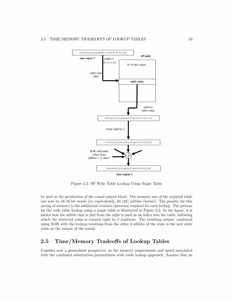
Figure 2.2: SP Wide Table Lookup Using Single Table
be used in the production of the round output block. The memory size of the required tablecan now be 16 16-bit words (or, equivalently, 64 (32) nibbles (bytes)). The penalty for thissaving of memory is the additional rotation operation required for each lookup. The processfor the wide table lookup using a single table is illustrated in Figure 2.2. In the figure, it isshown how the nibble that is 2nd from the right is used as an index into the table, followingwhich the retrieved value is rotated right by 2 positions. The resulting output, combinedusing XOR with the lookup/rotations from the other 3 nibbles of the state is the new statevalue at the output of the round.
2.5 Time/Memory Tradeoffs of Lookup Tables
Consider now a generalized perspective on the memory requirements and speed associatedwith the combined substitution/permutation wide table lookup approach. Assume that an
34 CHAPTER 2. SOFTWARE IMPLEMENTATION
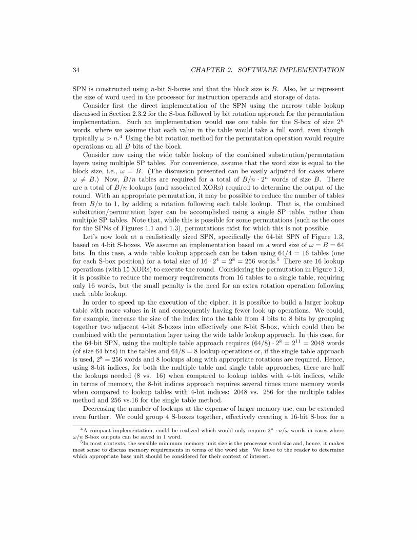
SPN is constructed using n-bit S-boxes and that the block size is B. Also, let ω representthe size of word used in the processor for instruction operands and storage of data.
Consider first the direct implementation of the SPN using the narrow table lookupdiscussed in Section 2.3.2 for the S-box followed by bit rotation approach for the permutationimplementation. Such an implementation would use one table for the S-box of size 2n
words, where we assume that each value in the table would take a full word, even thoughtypically ω > n.4 Using the bit rotation method for the permutation operation would requireoperations on all B bits of the block.
Consider now using the wide table lookup of the combined substitution/permutationlayers using multiple SP tables. For convenience, assume that the word size is equal to theblock size, i.e., ω = B. (The discussion presented can be easily adjusted for cases whereω 6= B.) Now, B/n tables are required for a total of B/n · 2n words of size B. Thereare a total of B/n lookups (and associated XORs) required to determine the output of theround. With an appropriate permutation, it may be possible to reduce the number of tablesfrom B/n to 1, by adding a rotation following each table lookup. That is, the combinedsubsitution/permutation layer can be accomplished using a single SP table, rather thanmultiple SP tables. Note that, while this is possible for some permutations (such as the onesfor the SPNs of Figures 1.1 and 1.3), permutations exist for which this is not possible.
Let’s now look at a realistically sized SPN, specifically the 64-bit SPN of Figure 1.3,based on 4-bit S-boxes. We assume an implementation based on a word size of ω = B = 64bits. In this case, a wide table lookup approach can be taken using 64/4 = 16 tables (onefor each S-box position) for a total size of 16 · 24 = 28 = 256 words.5 There are 16 lookupoperations (with 15 XORs) to execute the round. Considering the permutation in Figure 1.3,it is possible to reduce the memory requirements from 16 tables to a single table, requiringonly 16 words, but the small penalty is the need for an extra rotation operation followingeach table lookup.
In order to speed up the execution of the cipher, it is possible to build a larger lookuptable with more values in it and consequently having fewer look up operations. We could,for example, increase the size of the index into the table from 4 bits to 8 bits by groupingtogether two adjacent 4-bit S-boxes into effectively one 8-bit S-box, which could then becombined with the permutation layer using the wide table lookup approach. In this case, forthe 64-bit SPN, using the multiple table approach requires (64/8) · 28 = 211 = 2048 words(of size 64 bits) in the tables and 64/8 = 8 lookup operations or, if the single table approachis used, 28 = 256 words and 8 lookups along with appropriate rotations are required. Hence,using 8-bit indices, for both the multiple table and single table approaches, there are halfthe lookups needed (8 vs. 16) when compared to lookup tables with 4-bit indices, whilein terms of memory, the 8-bit indices approach requires several times more memory wordswhen compared to lookup tables with 4-bit indices: 2048 vs. 256 for the multiple tablesmethod and 256 vs.16 for the single table method.
Decreasing the number of lookups at the expense of larger memory use, can be extendedeven further. We could group 4 S-boxes together, effectively creating a 16-bit S-box for a
4A compact implementation, could be realized which would only require 2n · n/ω words in cases whereω/n S-box outputs can be saved in 1 word.
5In most contexts, the sensible minimum memory unit size is the processor word size and, hence, it makesmost sense to discuss memory requirements in terms of the word size. We leave to the reader to determinewhich appropriate base unit should be considered for their context of interest.
2.6. BIT-SLICE IMPLEMENTATIONS 35
Index Size Multiple Tables Memory Single Table Memory # Lookups(64-bit words) (64-bit words)
4 28 = 256 24 = 16 168 211 = 2048 28 = 256 816 218 = 262144 216 = 65536 4
Table 2.4: Tradeoffs for Wide Table Lookup (64-bit SPN using 4-bit S-boxes)
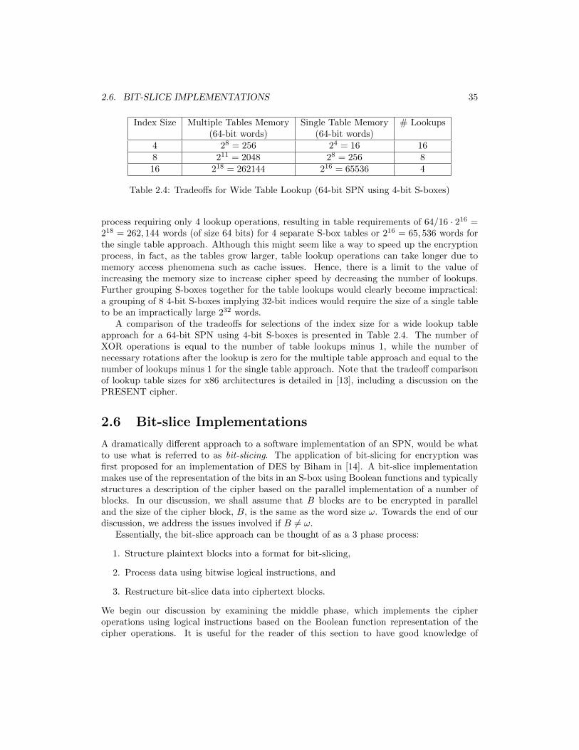
process requiring only 4 lookup operations, resulting in table requirements of 64/16 · 216 =218 = 262, 144 words (of size 64 bits) for 4 separate S-box tables or 216 = 65, 536 words forthe single table approach. Although this might seem like a way to speed up the encryptionprocess, in fact, as the tables grow larger, table lookup operations can take longer due tomemory access phenomena such as cache issues. Hence, there is a limit to the value ofincreasing the memory size to increase cipher speed by decreasing the number of lookups.Further grouping S-boxes together for the table lookups would clearly become impractical:a grouping of 8 4-bit S-boxes implying 32-bit indices would require the size of a single tableto be an impractically large 232 words.
A comparison of the tradeoffs for selections of the index size for a wide lookup tableapproach for a 64-bit SPN using 4-bit S-boxes is presented in Table 2.4. The number ofXOR operations is equal to the number of table lookups minus 1, while the number ofnecessary rotations after the lookup is zero for the multiple table approach and equal to thenumber of lookups minus 1 for the single table approach. Note that the tradeoff comparisonof lookup table sizes for x86 architectures is detailed in [13], including a discussion on thePRESENT cipher.
2.6 Bit-slice Implementations
A dramatically different approach to a software implementation of an SPN, would be whatto use what is referred to as bit-slicing. The application of bit-slicing for encryption wasfirst proposed for an implementation of DES by Biham in [14]. A bit-slice implementationmakes use of the representation of the bits in an S-box using Boolean functions and typicallystructures a description of the cipher based on the parallel implementation of a number ofblocks. In our discussion, we shall assume that B blocks are to be encrypted in paralleland the size of the cipher block, B, is the same as the word size ω. Towards the end of ourdiscussion, we address the issues involved if B 6= ω.
Essentially, the bit-slice approach can be thought of as a 3 phase process:
1. Structure plaintext blocks into a format for bit-slicing,
2. Process data using bitwise logical instructions, and
3. Restructure bit-slice data into ciphertext blocks.
We begin our discussion by examining the middle phase, which implements the cipheroperations using logical instructions based on the Boolean function representation of thecipher operations. It is useful for the reader of this section to have good knowledge of
36 CHAPTER 2. SOFTWARE IMPLEMENTATION
Boolean functions, Boolean algebra, and/or combinational logic design techniques. At theend of this section, we present an example of the 16-bit SPN to clarify the approach.
2.6.1 Bit-slicing the S-box
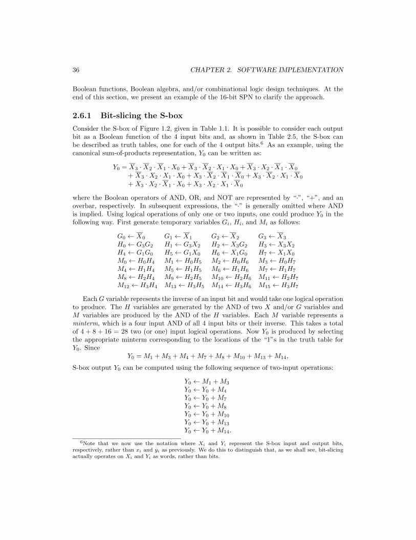
Consider the S-box of Figure 1.2, given in Table 1.1. It is possible to consider each outputbit as a Boolean function of the 4 input bits and, as shown in Table 2.5, the S-box canbe described as truth tables, one for each of the 4 output bits.6 As an example, using thecanonical sum-of-products representation, Y0 can be written as:
Y0 = X3 ·X2 ·X1 ·X0 +X3 ·X2 ·X1 ·X0 +X3 ·X2 ·X1 ·X0
+ X3 ·X2 ·X1 ·X0 +X3 ·X2 ·X1 ·X0 +X3 ·X2 ·X1 ·X0
+ X3 ·X2 ·X1 ·X0 +X3 ·X2 ·X1 ·X0
where the Boolean operators of AND, OR, and NOT are represented by “·”, “+”, and anoverbar, respectively. In subsequent expressions, the “·” is generally omitted where ANDis implied. Using logical operations of only one or two inputs, one could produce Y0 in thefollowing way. First generate temporary variables Gi, Hi, and Mi as follows:
G0 ← X0 G1 ← X1 G2 ← X2 G3 ← X3
H0 ← G3G2 H1 ← G3X2 H2 ← X3G2 H3 ← X3X2
H4 ← G1G0 H5 ← G1X0 H6 ← X1G0 H7 ← X1X0
M0 ← H0H4 M1 ← H0H5 M2 ← H0H6 M3 ← H0H7
M4 ← H1H4 M5 ← H1H5 M6 ← H1H6 M7 ← H1H7
M8 ← H2H4 M9 ← H2H5 M10 ← H2H6 M11 ← H2H7
M12 ← H3H4 M13 ← H3H5 M14 ← H3H6 M15 ← H3H7
EachG variable represents the inverse of an input bit and would take one logical operationto produce. The H variables are generated by the AND of two X and/or G variables andM variables are produced by the AND of the H variables. Each M variable represents aminterm, which is a four input AND of all 4 input bits or their inverse. This takes a totalof 4 + 8 + 16 = 28 two (or one) input logical operations. Now Y0 is produced by selectingthe appropriate minterm corresponding to the locations of the “1”s in the truth table forY0. Since
Y0 = M1 +M3 +M4 +M7 +M8 +M10 +M13 +M14,
S-box output Y0 can be computed using the following sequence of two-input operations:
Y0 ←M1 +M3
Y0 ← Y0 +M4
Y0 ← Y0 +M7
Y0 ← Y0 +M8
Y0 ← Y0 +M10
Y0 ← Y0 +M13
Y0 ← Y0 +M14.
6Note that we now use the notation where Xi and Yi represent the S-box input and output bits,respectively, rather than xi and yi as previously. We do this to distinguish that, as we shall see, bit-slicingactually operates on Xi and Yi as words, rather than bits.

2.6. BIT-SLICE IMPLEMENTATIONS 37
X3X2X1X0 Y3 Y2 Y1 Y00000 1 1 0 00001 0 1 0 10010 0 1 1 00011 1 0 1 10100 1 0 0 10101 0 0 0 00110 1 0 1 00111 1 1 0 11000 0 0 1 11001 1 1 1 01010 1 1 1 11011 1 0 0 01100 0 1 0 01101 0 1 1 11110 0 0 0 11111 0 0 1 0
Table 2.5: Truth Table for S-box of Table 1.1(All values in binary.)
To generate one output bit of the S-box, Y0, in this way would require at total of 35operations, 28 to produce the G, H, and M variables and 7 more to generate Y0 from theM variables.7 This is a lot of operations. However, consider that the canonical expressionsfor the remaining 3 outputs of the S-box, Y1, Y2, and Y3, are:
Y1 = M2 +M3 +M6 +M8 +M9 +M10 +M13 +M15,
Y2 = M0 +M1 +M2 +M7 +M9 +M10 +M12 +M13,
andY3 = M0 +M3 +M4 +M6 +M7 +M9 +M10 +M11.
Since the M variables only need to be produced once, to generate the output bits of theS-boxes takes a total of 28 + 4 · 7 = 56 operations or 56/4 = 14 operations on average peroutput bit.8
It is apparent that 14 operations per bit is not efficient. As we shall see, a major challengefor bit-slicing is finding a minimized form of the Boolean functions which ensures that themaximum efficiency for the software implementation of the Boolean function is achieved. Forour example, can we reduce the average number of Boolean operations to produce an outputbit to something substantially less that 14? In fact, for the PRESENT S-box of Table 1.1, it
7Since Y0 only needs 8 of the 16 M values, strictly speaking only 20 + 7 = 27 operations are needed forY0. However, all 16 M values must be calculated for the remaining outputs in any case.
8The number of operations can be further reduced to a small degree by calculating temporary variablesrepresenting the sum of pairs of M bits which are used to produce multiple output bits. For example,calculating M9 +M10 and saving the result in a variable could reduce the number of operations by two sincethe variable can be used to generate Y1, Y2, and Y3.

38 CHAPTER 2. SOFTWARE IMPLEMENTATION
can be shown that the following simple Boolean function can be used to produce the outputbit, Y0 [15]9:
Y0 = X0 ⊕X3 ⊕X2 · (X1 ⊕X2)
which can be structured as the following sequence of two-input logic operations, making useof variables, Ti:
T1 ← X1 ⊕X2
T2 ← X2 · T1T3 ← X3 ⊕ T2Y0 ← X0 ⊕ T3.
(2.1)
The remaining outputs can be subsequently generated using the following process [15]:
T2 ← T1 · T3T1 ← T1 ⊕ Y0T2 ← T2 ⊕X2
T4 ← X0 + T2Y1 ← T1 ⊕ T4
T4 ← X0
T2 ← T2 ⊕ T4Y3 ← Y1 ⊕ T2
T2 ← T2 + T1Y2 ← T2 ⊕ T3.
(2.2)
The total number of logical operations is therefore only 14 to produce the 4 output bits!Hence, the average number of operations per bit is only 3.5, substantially reduced over theprevious analysis’ average of 14 operations per bit.
Let us now consider how we can make use of Boolean expressions to efficiently implementthe S-box in software. For convenience, we shall initially assume that the block size of thecipher, B, is equal to the size of the words used as operands in processor instructions, ω,and let ω = B = 64. Consider that we have four 64-bit words, X3, X2, X1, and X0, witheach word corresponding to an input bit of the S-box. That is, Xi is a word containinginformation for input bit xi of an S-box (as illustrated in Figure 1.2), with each of the 64bits of Xi corresponding to the same S-box input bit associated with the encryption of 64different plaintext blocks. More specifically, consider an S-box in a particular round of thecipher has its four input bits represented by the word Xi = [xi,63xi,62...xi,0], i ∈ {0, 1, 2, 3},and, within this word, bit j, 0 ≤ j ≤ 63, represented as xi,j , represents input i to the S-boxfor the j-th plaintext block.
Now, assuming that Y0 = [y0,63y0,62...y0,0] is a 64-bit word that represents the S-boxoutput bit y0 for all 64 encryptions. It is possible to produce all 4 S-box output bits for all64 blocks in parallel by using (2.1) and (2.2), where the logical operations are performed inparallel on all bits of the word using the processor’s bitwise logical instructions. However,
9Methods used to determine simple Boolean functions made up of 2-input operations to compute S-boxoutput bits is beyond the scope of this article.

2.6. BIT-SLICE IMPLEMENTATIONS 39
executing these instructions produces S-box output bits for 64 different blocks. Hence,although it may seem costly to implement the Boolean function in software instructions, theparallel nature of the process gives the potential for improved speed up compared to otherapproaches such as the wide table lookup approach.
Using this process for our sample S-box, from (2.1) and (2.2), 14 instructions produces4 output bits of an S-box for 64 parallel encryptions, meaning the average number ofinstructions to produce an S-box output bit value across all encryptions is (14/4)/64 = 0.055.For the 64-bit cipher, it would take 14 · 16 = 224 instructions to produce the output of thesubstitution layer (16 S-boxes in total) for 64 parallel encryptions, which is equivalent toan average of 224/64 = 3.5 instructions to produce the output of a substitution layer forthe encryption of one block. This can be compared to the multiple table lookup approachusing a 4-bit index, which would require 16 table lookups and 15 XOR instructions for thesubstitution layer applied to each block. Hence, using bit-slicing for the substitution layer,when compared to the wide table lookup method, it appears that there is a potential forspeed-up on the order of (16 + 15)/3.5 ≈ 9.10 Ignoring any memory requirements for thekey schedule, bit-slicing would have modest memory requirements requiring B = 64 wordsto store the words representing each bit of the state for the parallel encryptions. Dependingon the nature of the key schedule and its implementation, the memory requirements to storeand produce round keys could be significantly more.
Although there seems to be great potential using bit-slicing, there are two significantchallenges: (1) an efficient Boolean function representation of the S-box must be found,and (2) the plaintext block from 64 different encryptions must be restructured into thedata structure appropriate for bit-slicing where words should contain information from thesame bit from numerous blocks. In the next section, we discuss the the nature of the datarestructuring. For small S-boxes, such as 4-bit S-boxes found in lightweight ciphers suchas PRESENT, simple 4-bit Boolean functions may be found (such as illustrated previously)that can lead to potentially very efficient bit-slice implementations. However, for larger S-boxes, such as the 8-bit S-boxes found in AES, the 8-bit Boolean functions are substantiallymore complex than for smaller functions. Consider that the canonical form of the Booleanfunction representing an AES S-box consists of 128 minterms, each with 8 inputs (takenfrom the S-box input bits or their inverses). Of course, this can be reduced using logicminimization techniques, but there will still be clearly many two-operand logic instructionsto produce the 8-bit output of an S-box. In fact, the average number of instructions per bitfor the AES S-boxes is much larger than for 4-bit S-boxes and, in general, bit-slicing is bestsuited to systems comprised of small S-boxes.
2.6.2 Restructuring the Data for Bit-Slicing
Since the idea behind bit-slicing is to have multiple blocks of plaintext being encryptedsimultaneously by executing the logical operations representing the cipher components usingbitwise logical instructions on words, it is necessary to restructure the data representing the
10This is a gross simplification. This speed-up only applies to the substitution portion of the processingand presumes the convenience of data being structured for bit-slicing. Also, the timing cost of differentinstructions is not the same. For example, certainly a table lookup operation (which includes the setup stepsfor the index, as well as the actual memory access) is not equivalent in timing cost to a simple XOR of 2operands.

40 CHAPTER 2. SOFTWARE IMPLEMENTATION
plaintext into an appropriate format. Let us continue assuming ω = B = 64. At theinput of the system, for the 64-bit SPN, we shall assume that we have 64 plaintext blocksto encrypt, with each block stored in a word. We can visualize the data as organizedinto a matrix of plaintext where the words containing blocks map onto rows containing 64elements each consisting of 1 bit of a plaintext and each column of the matrix representsthe position of bits within the block. For example, the leftmost column is bit 63 of theplaintext and the rightmost is bit 0 of the plaintext. We label this plaintext maxtrix as P †
and let the rows of P †, from top to bottom, be P †63, P†62, ..., P
†0 , each representing a different
plaintext block. Each block maps to a 64-bit word with the j-th bit of block, P †i , labelled
as p†i,j , j ∈ {0, 1, ...63}. Hence, we have the following representation:
P † =
P †63P †62P †61...
P †1P †0
=
p†63,63 p†63,62 p†63,61 ... p†63,1 p†63,0p†62,63 p†62,62 p†62,61 ... p†62,1 p†62,0p†61,63 p†61,62 p†61,61 ... p†61,1 p†61,0...
p†1,63 p†1,62 p†1,61 ... p†1,1 p†1,0p†0,63 p†0,62 p†0,61 ... p†0,1 p†0,0
.
To encrypt using bit-slicing, the bits of the plaintext matrix must be reassigned to thebit-slicing data structure, an 64×64 matrix of bits (represented by 64 rows of 64-bit words),
which we refer to as the bit-slicing state, D†, comprised of elements d†i,j , i, j ∈ {0, 1, ..., 63},where i represents the row (starting with 63 at the top) and j represents the column (startingwith 63 at the left). The resulting matrix representing the bit-slice state thus has the format:
D† =
D†63D†62D†61...
D†1D†0
=
d†63,63 d†63,62 d†63,61 ... d†63,1 d†63,0d†62,63 d†62,62 d†62,61 ... d†62,1 d†62,0d†61,63 d†61,62 d†61,61 ... d†61,1 d†61,0...
d†1,63 d†1,62 d†1,61 ... d†1,1 d†1,0d†0,63 d†0,62 d†0,61 ... d†0,1 d†0,0
.
The elements of D† are derived from the original plaintext block, P †, as follows:
d†i,j ← p†j,i
for all i, j ∈ {0, 1, ..., 63}. That is, the j-th bit of the i-th block of plaintext should beput into the i-th bit of the j-th word of D†. This is equivalent to saying that D† is atransposition of matrix P †. Similarly, after the completion of the encryption of all 64 blocksto produce the ciphertext blocks, the data in D† must be restructured back into one word(row) representing the bits of one block. In other words, we need to transpose D† to get theciphertext matrix, C†, following the encryption process. The flow of the encryption processfor bit-slicing can thus be summarized as follows:
{(P †)T → D†} =⇒ {Update D†using bit-slice encryption} =⇒ {(D†)T → C†}
where (·)T represents transposition of the argument matrix.

2.6. BIT-SLICE IMPLEMENTATIONS 41
For the encryption of 64 blocks, the two transposition operations on the 64×64 matricesresult in 2 × 64 × 64 = 213 variable assignments for an average of 128 such assignmentsper plaintext block. These operations are not needed for other encryption methods such asthe table lookup approaches. Hence, they indicate an overhead associated with bit-slicing.However, if the core Boolean function operations can be implemented efficiently, then thisoverhead may be small enough to ensure that bit-slicing is more efficient than methods suchas table lookup.
Also, it should be noted that, in practice, assembly language instructions on modernprocessors can allow some efficiencies in the movement of data bits within the words of datarepresenting the cipher data blocks. For example, in [16], assembly code is given for anefficient data restructuring.
To this point, we have discussed how to structure the implementation to determine theoutput of an S-box by executing the appropriate Boolean operators of NOT, AND, OR, andXOR using bitwise logical instructions in software. We have discussed the need to transformdata at both the input (plaintext) and output (ciphertext) to ensure data is an appropriateformat for bit-slicing during the processing of the data. We emphasize again that unless aneffort is made to minimize the number of logical operations to realize the S-box, clearly thiswill not be as efficient as a table lookup approach. We need to finish our explanation byclarifying how the bit-slice data processing can be done for the other round function layers,the permutation and the key mixing.
2.6.3 Bit-slicing the Permutation and Key Mixing
We have focused on discussing the Boolean function representation of S-boxes and itsrelationship to bit-slicing. However, before we present a detailed example of bit-slicing, weshould comment on the other operations that comprise the round operation of the cipher.The permutation operation is a simple reordering of the bit positions and, hence, can beeasily incorporated into bit-slicing at negligible cost: instead of assigning the output of theBoolean operations to the word representing the state bit at the output of the substitutionlayer, the output can be assigned to the word representing the bit position to which thepermutation will move the S-box output bit. For example, for the 64-bit SPN using thepermutation in Table 1.5, the word representing the state bit 19 (at the output of thesubstitution), will be assigned into the word representing state bit 52, which is the positionto which bit 19 is moved due to the permutation.
For the key mixing operation, incorporation into the bit-slicing process is also trivial.Since most applications will use the same key for a large number of plaintext data blocks,it is reasonable to assume all blocks being encrypted by one pass through the bit-slicedcipher implementation are using the same key and, hence, the round keys are the same foreach block. In general for a B-bit SPN, for bit-slicing, the round key data structure shouldalso represent a B × B matrix, stored in the system as B words of size B-bits, where eachword represents one bit position within the cipher round key and each bit within the wordrepresents the round key bit value for each of the B blocks being encrypted. However, sinceall round keys are the same for all encryptions, all words (which are the rows of the B ×Bmatrix) of the bit-slice round key structure must be all “0”s or all “1”s. Using bit-slicing, itis possible to prepare and store the words to represent the round key bits prior to processingthe encryption of any plaintext blocks using a particular cipher key. In order to execute key
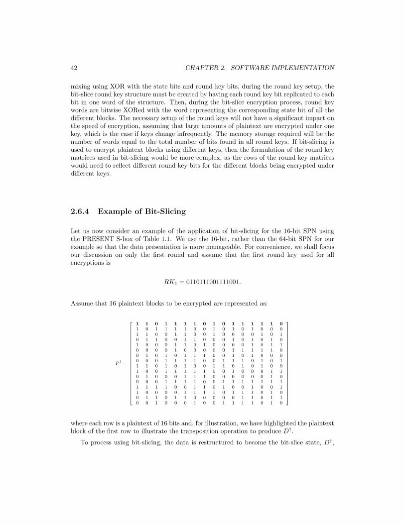
42 CHAPTER 2. SOFTWARE IMPLEMENTATION
mixing using XOR with the state bits and round key bits, during the round key setup, thebit-slice round key structure must be created by having each round key bit replicated to eachbit in one word of the structure. Then, during the bit-slice encryption process, round keywords are bitwise XORed with the word representing the corresponding state bit of all thedifferent blocks. The necessary setup of the round keys will not have a significant impact onthe speed of encryption, assuming that large amounts of plaintext are encrypted under onekey, which is the case if keys change infrequently. The memory storage required will be thenumber of words equal to the total number of bits found in all round keys. If bit-slicing isused to encrypt plaintext blocks using different keys, then the formulation of the round keymatrices used in bit-slicing would be more complex, as the rows of the round key matriceswould need to reflect different round key bits for the different blocks being encrypted underdifferent keys.
2.6.4 Example of Bit-Slicing
Let us now consider an example of the application of bit-slicing for the 16-bit SPN usingthe PRESENT S-box of Table 1.1. We use the 16-bit, rather than the 64-bit SPN for ourexample so that the data presentation is more manageable. For convenience, we shall focusour discussion on only the first round and assume that the first round key used for allencryptions is
RK1 = 0110111001111001.
Assume that 16 plaintext blocks to be encrypted are represented as:
P†=
1 1 0 1 1 1 1 0 1 0 1 1 1 1 1 01 0 1 1 1 1 0 0 1 0 1 0 1 0 0 01 1 0 0 1 1 0 0 1 0 0 0 0 1 0 10 1 1 0 0 1 1 0 0 0 1 0 1 0 1 01 0 0 0 1 1 0 1 0 0 0 0 1 0 1 10 0 0 0 1 0 0 0 0 0 1 1 1 1 1 00 1 0 1 0 1 1 1 0 0 1 0 1 0 0 00 0 0 1 1 1 1 0 0 1 1 1 0 1 0 11 1 0 1 0 1 0 0 1 1 0 1 0 1 0 01 0 0 1 1 1 1 1 0 0 1 0 0 0 1 10 1 0 0 0 1 1 1 0 0 0 0 0 0 1 00 0 0 1 1 1 1 0 0 1 1 1 1 1 1 11 1 1 1 0 0 1 1 0 1 0 0 1 0 0 11 0 0 0 0 1 1 1 1 0 1 1 1 0 1 00 1 1 0 1 1 0 0 0 0 0 1 1 0 1 10 0 1 0 0 0 1 0 0 1 1 1 1 0 1 0
where each row is a plaintext of 16 bits and, for illustration, we have highlighted the plaintextblock of the first row to illustrate the transposition operation to produce D†.
To process using bit-slicing, the data is restructured to become the bit-slice state, D†,
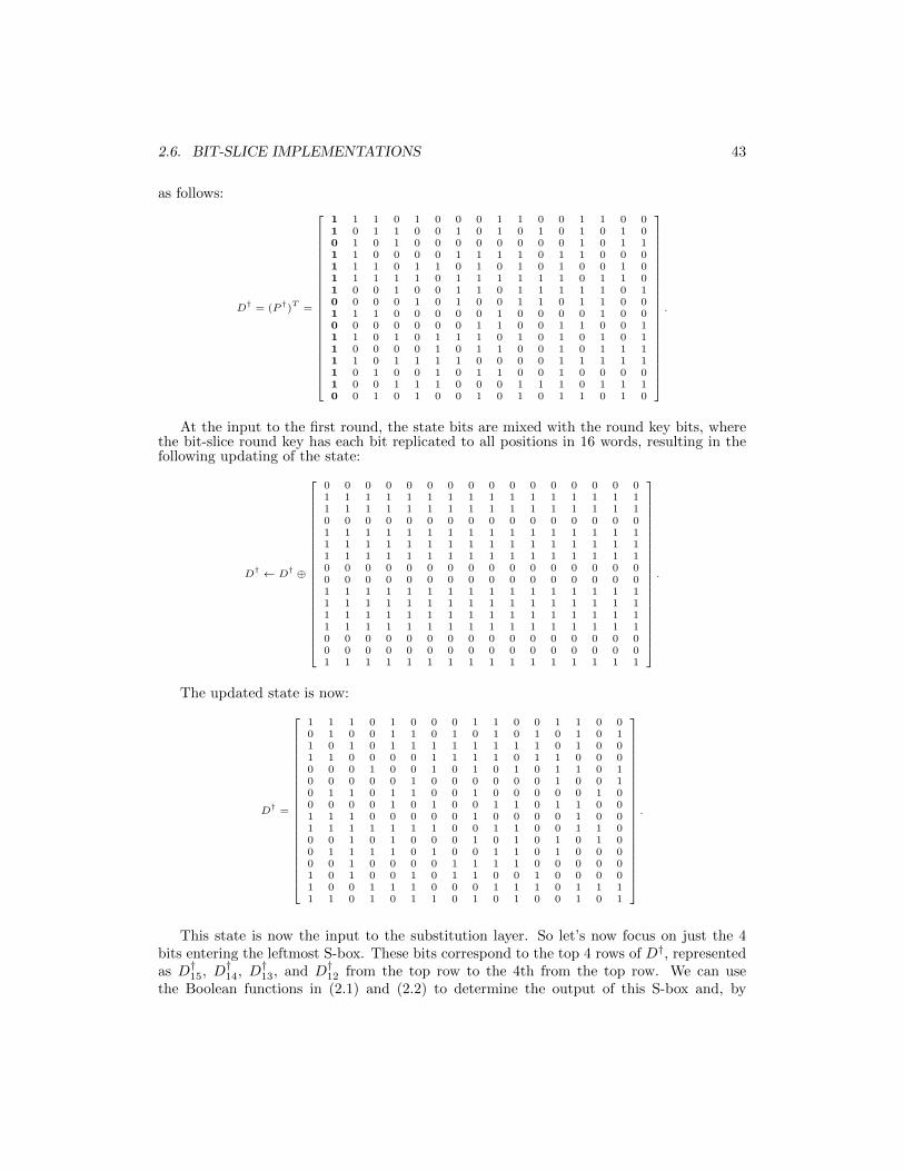
2.6. BIT-SLICE IMPLEMENTATIONS 43
as follows:
D†= (P
†)T
=
1 1 1 0 1 0 0 0 1 1 0 0 1 1 0 01 0 1 1 0 0 1 0 1 0 1 0 1 0 1 00 1 0 1 0 0 0 0 0 0 0 0 1 0 1 11 1 0 0 0 0 1 1 1 1 0 1 1 0 0 01 1 1 0 1 1 0 1 0 1 0 1 0 0 1 01 1 1 1 1 0 1 1 1 1 1 1 0 1 1 01 0 0 1 0 0 1 1 0 1 1 1 1 1 0 10 0 0 0 1 0 1 0 0 1 1 0 1 1 0 01 1 1 0 0 0 0 0 1 0 0 0 0 1 0 00 0 0 0 0 0 0 1 1 0 0 1 1 0 0 11 1 0 1 0 1 1 1 0 1 0 1 0 1 0 11 0 0 0 0 1 0 1 1 0 0 1 0 1 1 11 1 0 1 1 1 1 0 0 0 0 1 1 1 1 11 0 1 0 0 1 0 1 1 0 0 1 0 0 0 01 0 0 1 1 1 0 0 0 1 1 1 0 1 1 10 0 1 0 1 0 0 1 0 1 0 1 1 0 1 0
.
At the input to the first round, the state bits are mixed with the round key bits, wherethe bit-slice round key has each bit replicated to all positions in 16 words, resulting in thefollowing updating of the state:
D† ← D
† ⊕
0 0 0 0 0 0 0 0 0 0 0 0 0 0 0 01 1 1 1 1 1 1 1 1 1 1 1 1 1 1 11 1 1 1 1 1 1 1 1 1 1 1 1 1 1 10 0 0 0 0 0 0 0 0 0 0 0 0 0 0 01 1 1 1 1 1 1 1 1 1 1 1 1 1 1 11 1 1 1 1 1 1 1 1 1 1 1 1 1 1 11 1 1 1 1 1 1 1 1 1 1 1 1 1 1 10 0 0 0 0 0 0 0 0 0 0 0 0 0 0 00 0 0 0 0 0 0 0 0 0 0 0 0 0 0 01 1 1 1 1 1 1 1 1 1 1 1 1 1 1 11 1 1 1 1 1 1 1 1 1 1 1 1 1 1 11 1 1 1 1 1 1 1 1 1 1 1 1 1 1 11 1 1 1 1 1 1 1 1 1 1 1 1 1 1 10 0 0 0 0 0 0 0 0 0 0 0 0 0 0 00 0 0 0 0 0 0 0 0 0 0 0 0 0 0 01 1 1 1 1 1 1 1 1 1 1 1 1 1 1 1
.
The updated state is now:
D†=
1 1 1 0 1 0 0 0 1 1 0 0 1 1 0 00 1 0 0 1 1 0 1 0 1 0 1 0 1 0 11 0 1 0 1 1 1 1 1 1 1 1 0 1 0 01 1 0 0 0 0 1 1 1 1 0 1 1 0 0 00 0 0 1 0 0 1 0 1 0 1 0 1 1 0 10 0 0 0 0 1 0 0 0 0 0 0 1 0 0 10 1 1 0 1 1 0 0 1 0 0 0 0 0 1 00 0 0 0 1 0 1 0 0 1 1 0 1 1 0 01 1 1 0 0 0 0 0 1 0 0 0 0 1 0 01 1 1 1 1 1 1 0 0 1 1 0 0 1 1 00 0 1 0 1 0 0 0 1 0 1 0 1 0 1 00 1 1 1 1 0 1 0 0 1 1 0 1 0 0 00 0 1 0 0 0 0 1 1 1 1 0 0 0 0 01 0 1 0 0 1 0 1 1 0 0 1 0 0 0 01 0 0 1 1 1 0 0 0 1 1 1 0 1 1 11 1 0 1 0 1 1 0 1 0 1 0 0 1 0 1
.
This state is now the input to the substitution layer. So let’s now focus on just the 4bits entering the leftmost S-box. These bits correspond to the top 4 rows of D†, representedas D†15, D†14, D†13, and D†12 from the top row to the 4th from the top row. We can usethe Boolean functions in (2.1) and (2.2) to determine the output of this S-box and, by

44 CHAPTER 2. SOFTWARE IMPLEMENTATION
incorporating the permutation, place these 4 bits into the correct new positions withinthe state. We now let Yi, i ∈ {0, 1, .., 15}, represent the words for each output bit of thesubstitution layer (rather than just an individual S-box). Hence, bits Y15, Y14, Y13, and Y12represent the outputs bits of the leftmost S-box. The following operations must occur:
T1 ← D†13 ⊕D†14 = [AFF4]⊕ [4D55] = [E2A1]
T2 ← D†14 · T1 = [4D55] · [E2A1] = [4001]
T3 ← D†15 ⊕ T2 = [E8CC]⊕ [4001] = [A8CD]
Y12 ← D†12 ⊕ T3 = [C3D8]⊕ [A8CD] = [6B15]
T2 ← T1 · T3 = [E2A1] · [A8CD] = [A081]T1 ← T1 ⊕ Y12 = [E2A1]⊕ [6B15] = [89B4]
T2 ← T2 ⊕D†14 = [A081]⊕ [4D55] = [EDD4]
T4 ← D†12 + T2 = [C3D8] + [EDD4] = [EFDC]Y13 ← T1 ⊕ T4 = [89B4]⊕ [EFDC] = [6668]
T4 ← D†12 = [C3D8] = [3C27]T2 ← T2 ⊕ T4 = [EDD4]⊕ [3C27] = [D1F3]Y15 ← Y13 ⊕ T2 = [6668]⊕ [D1F3] = [B79B]
T2 ← T2 + T1 = [D1F3] + [89B4] = [D9F7]Y14 ← T2 ⊕ T3 = [D9F7]⊕ [A8CD] = [713A]...
D†15 ← Y15 = [B79B] ... D†11 ← Y14 = [713A] ...
D†7 ← Y13 = [6668] ... D†3 ← Y12 = [6B15]
Note that we have used hexadecimal notation to represent 16-bit words for convenience ofpresentation. The last four assignments update state bits based on the permutation andshould only be done after similarly logical operations are applied to produce words Y11 toY0, with the resulting assignments to the appropriate D†i words to finalize the output of thesubstitution/permutation combination.
After the application of the Boolean functions and permutation to all bits, the resultingstate matrix becomes
D†=
1 0 1 1 0 1 1 1 1 0 0 1 1 0 1 1...0 1 1 1 0 0 0 1 0 0 1 1 1 0 1 0...0 1 1 0 0 1 1 0 0 1 1 0 1 0 0 0...0 1 1 0 1 0 1 1 0 0 0 1 0 1 0 1...
.
where we only illustrate the four rows for D†15, D†11, D†7, and D†3 and leave the remainingrows as an exercise for the reader. Subsequent rounds would follow similarly. After the lastround (which recall would have the permutation replaced with an extra key mixing), thebit-slice state needs to be restructured so that the resulting data is formatted as 16 rows of16 bits, where each row contains a ciphertext block (rather than a particular bit from allblocks). This is similar to the data structuring operation at the start of encryption and isthe equivalent to C† = (D†)T .

2.6. BIT-SLICE IMPLEMENTATIONS 45
2.6.5 Other Structures for Bit-slicing
We have described constructing a bit-slice implementation assuming that B blocks are to beencrypted in parallel in an implementation where the word size ω is the same as the blocksize of the cipher, that is, ω = B. But clearly it is possible that, in some circumstances,the word size will not equal the block size. How do we structure a bit-slice implementationwhen B 6= ω? Consider the two cases (1) ω > B and (2) B > ω.
For the first case, ω > B, and, for convenience in our discussions, let ω = 128 and B = 64.For this case, it is possible to apply bit-slicing by treating the two 64-bit blocks as one 128-bit superblock and constructing the appropriate bit-slice process with 128 simultaneouslyencryptions. In this scenario, the permutation does not mix bits between the 2 blocksmaking up the superblock. Since there will 128 superblocks processed in parallel, in fact,there will be 256 64-bit blocks that will be processed with one pass through the bit-slicestructure.
For the second case, B > ω, and, for convenience in our discussions, let ω = 32 andB = 128. One possible approach is to structure the bit-slicing around a virtual 128-bitword, which is made up of four 32 words. So in this case, 128 encryptions will be done inparallel. Each logical operation on the bits from 128 encryptions will need 4 instructions,one for each word making up the 128-bit virtual word. Essentially, each operation on the128-bit virtual word, will require the equivalent of 4 instructions on 32-bit operands.
To this point, we have assumed that the number of blocks encrypted in parallel using bit-slicing is the same as the block size (or superblock size). Although this can be particularlyefficient, it presents challenges in environments where data is to be encrypted in smallbatches, since a large number of blocks must be collected before the data can be restructuredand processed using bit-slicing. However, it is also possible to encrypt fewer than B blocksin parallel. Consider for example, the 64-bit SPN where 16 blocks are encrypted in parallelby using a bit-slicing state, D†, of 64 rows and 16 columns. In this case, each bitwise logicoperator is only operating on 16 bits of the ω bits of a word. If ω is 64, for example, thiswould be only 1/4 of the efficiency of operating on 64 parallel blocks. It is also possibleto pack data into words (corresponding to a row of D†) so that more than one bit of ablock occurs in each row. For example, rather than 64 rows with 16 columns to implementencryption of 16 blocks, one could pack the data into an matrix of 16 rows and 64 columns,where each row would contain bit i from 16 different blocks and also, bits i+ 16, i+ 32, andi+ 64 from all 16 blocks. This is possible because each output bit of an S-box correspondingto a particular position is produced using the same Boolean function for all S-boxes. In thisapproach, instructions available in the processor would have to be exploited to efficientlymove data around to achieve the permutation operation. This is done for PRESENT in [17].
In some cases, ciphers have been designed to be specifically suited to implementationusing bit-slicing [18] [19] [20]. Such designs, in addition to being efficiently implementableusing a software bit-slicing method, are also very compact for hardware implementationand can be implemented to be resistant to side channel attacks. It has even be found,applying bit-slicing to CTR mode and taking advantage of available processor instructions,it is possible to develop a high throughput implementation of AES [21].

46 CHAPTER 2. SOFTWARE IMPLEMENTATION
2.7 Software Implementation of Cipher Modes
As presented in Section 1.4, block ciphers are applied using one of many possible modes ofoperation, such as ECB, CBC, and CTR. In all cases, certainly a table lookup implementationwould be a useful approach to implementing an efficient encryption. The input to theblock cipher “encryption” operation would be plaintext for ECB, plaintext XORed with theprevious ciphertext for CBC, and a counter value for CTR mode. Table lookup approachesrepresent a fast implementation that can be used effectively for modes which must processplaintext sequentially, that is, modes for which the previous ciphertext is generated beforethe current plaintext is processed. For example, CBC relies on using the previous ciphertextas part of the next block input and can only be used in applications which sequentiallyprocess plaintext data. ECB and CTR modes can be structured to execute one encryptionat a time and such applications can also benefit from an efficient table lookup approach.
Bit-slicing can be more efficient than table lookups in circumstances where the Booleanfunctions representing the S-boxes can be implemented using a small number of two-operandlogical instructions. However, if it is necessary to require the parallel processing of B inputblocks for efficient bit-slicing, issues can arise. In ECB mode, plaintext blocks could bebuffered and then encrypted when B plaintext blocks become available. In the case of CTRmode, the count is easily predictable and, hence, it is quite possible to process B blocks inparallel to produce keystream, which can then be stored for when B plaintext blocks areavailable to encrypt. However, using a bit-slice implementation is particularly problematicif the block cipher is used in CBC mode. Since, CBC mode relies on the previous ciphertextto prepare the next block input, only one block at a time can encrypted and parallelizingencryption as required for bit-slicing is not possible.11 Other feedback modes, such as outputfeedback (OFB) mode and cipher feedback (CFB) mode [12], also require linkages betweenconsecutive encryptions, making the parallelization needed for bit-slicing challenging.
Consider now CTR mode. The nature of the mode presents an opportunity to makeparticularly efficient use of bit-slicing, by eliminating some data restructuring. Normally, atthe output of a bit-slice process, the data is generally restructured from the bit-slice stateformat back to the general data format where words become ciphertext blocks. However, inCTR mode, the block cipher is used in encryption mode to produce a sequence of keystreamblocks, not ciphertext directly. If we followed the normal method and the output of thebit-slice process restructures the data, CTR mode would result in a conventional bit orderin the keystream of:
bit 1 of block 1⇒ bit 2 of block 1⇒ ...⇒ bit B of block 1⇒ bit 1 of block 2 ⇒ bit 2 of block 2⇒ ...
However, for an application of CTR mode, this restructuring operation at the output is notnecessary. The result of not restructuring the data format would be that keystream will benon-conventionally ordered as follows:
bit 1 of block 1⇒ bit 1 of block 2⇒ ...⇒ bit 1 of block B⇒ bit 2 of block 1⇒ bit 2 of block 2⇒ ...
11One could apply bit-slicing in CBC mode, if one could encrypt B independent, interleaved streams.However, it is possible in such a scenario that the streams could be using different keys and this would haveto be considered in the setup of the round key structure for bit-slicing.

2.8. SUMMARY 47
This ordering of keystream creates no more predictability in the keystream and, hence, can beconsidered as secure as the conventional ordering. However, since this is a non-conventionalway to generate the keystream in CTR mode, both the transmitter and receiver wouldhave to be in agreement of how to implement the mode. For example, it would not bepossible for the transmitter to use a bit-slice implementation and then, for efficiency, usethe non-conventional ordering, while the receiver uses a table lookup implementation anduses the conventional ordering. Of course, the receiver could use the table lookup methodand restructure the keystream to use the non-conventional ordering, thereby making itselfcompatible with the transmitter.
2.8 Summary
In this chapter, we have discussed software implementation approaches to block ciphers,using the 16-bit and 64-bit SPNs as case studies. Approaches have included table lookupmethods and bit-slicing. The wide table lookup approach can be used to combine theS-box and permutation operations into table lookups where the values stored in the tablerepresent the full block width with the S-box output bits moved into the appropriate positionswithin the block according to the permutation. The width of the table index (and theassociated size of the table) is somewhat adjustable allowing for tradeoffs between the speedof the implementation and the amount of memory required. Bit-slicing is a dramaticallydifferent approach to implementation and its value is highly dependent on finding a logicalrepresentation of the S-box which requires a small number of 2-operand logic gates. Dueto the necessary structuring of data, typically multiple blocks are encrypted in paralleland, hence, bit-slicing is most appropriate for applications which employ compatible modesof operation, such as counter mode. Finally, we note that other techniques exist for fastsoftware implementations which make explicit use of instructions of the SIMD architecturefound on modern processors. For example, the vector permutation (vperm) techniquedescribed in [22] [13] relies on the existence of shuffling instructions. Most significantly,processors now support an AES instruction set (AES-NI) designed to efficiently accelerateAES operations [4].

48 CHAPTER 2. SOFTWARE IMPLEMENTATION

Chapter 3
Hardware Implementation
We now turn our attention to hardware implementations of block ciphers, again focusingon SPNs. We discuss synchronous sequential logic designs that can be used for targettechnologies such as field-programmable arrays (FPGAs) and application-specific integratedcircuits (ASICs) realized for different CMOS technologies. The architectures that we discussin this section presume that the reader has a basic knowledge of digital hardware design,including concepts such as logic gates, registers, multiplexers, and synchronous sequentiallogic design aspects such as datapaths, controllers, and timing issues.1
Cryptographic applications fall on a spectrum with the two extremes being (1) highspeed/throughput (eg. core network routers) and (2) compact and often low power orenergy (eg. wireless sensor nodes or other IoT devices). We shall discuss hardware structureswhich can be used to target these two extremes, as well as applications falling somewherein between. In synchronous sequential logic designs, the speed or throughput of the blockcipher hardware implementation is determined by (1) the average number of ciphertextsproduced per clock cycle and (2) the frequency of the clock (which can be as high as theinverse of the minimum possible clock period). The complexity of a hardware design isoften characterized by (1) the number of logic gates required for a synthesized design, (2)the number of logic blocks used in an FPGA implementation, or (3) the area required inan ASIC implementation. Often, the design complexity is characterized as the number ofequivalent gates, where a gate is a 2-input NAND gate. In our discussions, we shall often use“area” when referring to a design’s complexity, where smaller area implies a more compactdesign.
In the following sections, we discuss various design strategies for encryption by describingsample designs. By necessity, these descriptions leave out some details so that we can focuson the main aspects of interest. We leave it to the reader to envision the potential structuresfor the components of the designs not specifically outlined.
1For convenience, we shall assume in our discussion that registers used to store data such as the cipherstate are loaded on the rising edge of the clock.
49
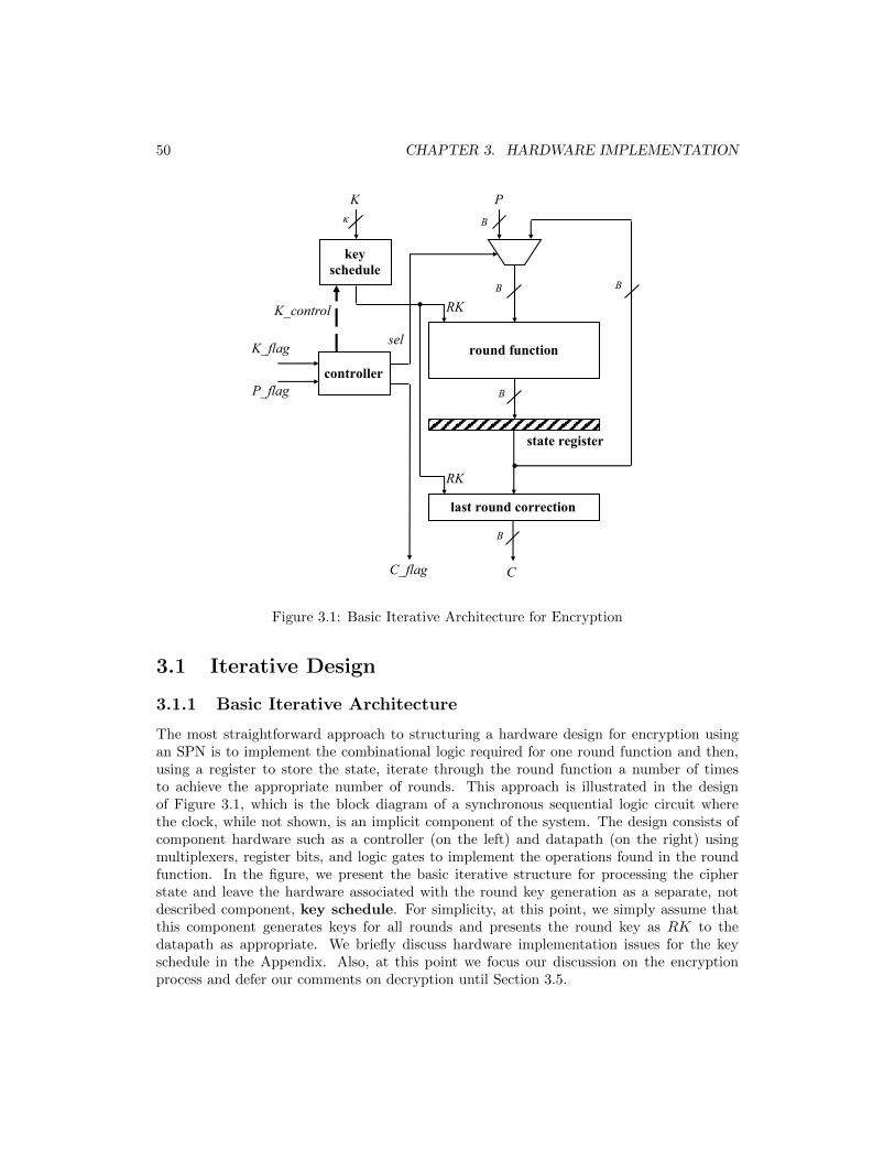
50 CHAPTER 3. HARDWARE IMPLEMENTATION
RK
k B
B B
RK K_control
C_flag
sel
P_flag
round function
state register
controller
key schedule
K P
K_flag
C
B
last round correction
B
Figure 3.1: Basic Iterative Architecture for Encryption
3.1 Iterative Design
3.1.1 Basic Iterative Architecture
The most straightforward approach to structuring a hardware design for encryption usingan SPN is to implement the combinational logic required for one round function and then,using a register to store the state, iterate through the round function a number of timesto achieve the appropriate number of rounds. This approach is illustrated in the designof Figure 3.1, which is the block diagram of a synchronous sequential logic circuit wherethe clock, while not shown, is an implicit component of the system. The design consists ofcomponent hardware such as a controller (on the left) and datapath (on the right) usingmultiplexers, register bits, and logic gates to implement the operations found in the roundfunction. In the figure, we present the basic iterative structure for processing the cipherstate and leave the hardware associated with the round key generation as a separate, notdescribed component, key schedule. For simplicity, at this point, we simply assume thatthis component generates keys for all rounds and presents the round key as RK to thedatapath as appropriate. We briefly discuss hardware implementation issues for the keyschedule in the Appendix. Also, at this point we focus our discussion on the encryptionprocess and defer our comments on decryption until Section 3.5.

3.1. ITERATIVE DESIGN 51
We now provide a rough description of the flow of the data through the encryptionsystem of Figure 3.1. The hardware for the basic iterative design will operate as follows.The controller will be comprised of a state machine that moves from control state to state asappropriate based on inputs to the controller and provides output control signals based onthe control state. Upon assertion of the K flag, the controller will use control signals in theK control interface to indicate to the key schedule module that the cipher key is availableat the κ-bit input K. Subsequent to the key input, plaintext will be available at B-bitinput P as signalled by input P flag. With the arrival of a plaintext block, the controllerwill set control signal sel to ensure that the data of P is selected by the multiplexer andpassed into the combinational logic of the round function, such that the output will beloaded into the B-bit state register on the next rising clock edge. The value stored inthe register represents the state of the cipher and in subsequent clock cycles, sel will beset for the multiplexer to select the feedback from the register as the input to the roundfunction logic. Each clock cycle with the feedback selection represents the processing of around and the appropriate round key RK must be presented by the key schedule module.After the R rounds of the cipher, the C flag signal is asserted to indicate to an externaldevice the B-bit output signal C (coming from the state register output and fed throughthe combinational logic module last round correction) is the valid ciphertext producedduring the encryption operation. Hence, for the basic iterative architecture, a ciphertextblock is produced every R clock cycles and the throughput is 1/(R · tclock) blocks/second,where tclock is the clock period.
Two factors in determining the clock timing requirements for the iterative architectureare (1) the propagation delay between register loads (including both the delays of the registerand combinational logic of the round hardware) and (2) the setup time of the register. Thepropagation delay of the register is the time from the rising clock edge to when the outputof the register becomes valid. The setup time of the register is the window of time before aclock edge during which the inputs to the register should be stable to avoid problems whenloading at the clock edge. In general, the circuit timing must satisfy the following expression:
tclock > tpd reg + tpd comb + tsetup (3.1)
where tpd reg is the propagation delay of the register, tpd comb is the propagation delay ofthe combinational logic in the round, and tsetup is the setup time of the register. Note thattpd comb is determined by propagation delay through the multiplexer, key mixing and S-boxlayers, with the permutation having no gates and, hence, negligible propagation delay.
Note that in Figure 3.1 the round function hardware is re-used for all rounds, includingthe last round. However, since the actual structure of the SPN requires a last round that ismodified from all other rounds, we have added at the output the last round correctionmodule. This module can correct the output of the last round function by applying theinverse permutation (and thereby removing the permutation from the last round) and addinga new key mixing operation with RK now set as the final round key value. We leave detailson how the key schedule block will generate and manage the necessary round keys to thereader to resolve.

52 CHAPTER 3. HARDWARE IMPLEMENTATION
d15 d11 d7 d3 d0
x0 x1 x2 x3
y0 y1 y2 y3
S-box Logic S-box Logic S-box Logic S-box Logic
!!"∗
rk15 rk7 rk11 ... ... ... rk3 ... rk0
... !!$∗ !%∗ !!∗ !&∗ !'∗
Figure 3.2: Round Function Logic for 16-bit SPN
3.1.2 Round Function Hardware
Let’s now consider the combinational logic that would comprise the round function. Forthe 16-bit SPN, this is illustrated in Figure 3.2, where di, d
∗i , and rki are used to represent
input bit i of the round function, output bit i of the round function, and bit i of thecurrent round key. The round function combinational logic can simply consist of the 3 layerscorresponding to the operations: key mixing, substitution, and permutation. The key mixingoperation is comprised of B 2-input XOR gates, where each gate has as inputs a state bitand the corresponding round key bit. The permutation layer represents a routing of bitpositions and is simply a matter of wiring, requiring no logic gates. The substitution logicwill be multi-level logic. It could be two-level sum-of-products (AND-OR) logic or product-of-sums (OR-AND) logic were each bit represents the output bit of an S-box and has as inputthe 4-bits of the corresponding S-box. The logic for each output can be minimized usingappropriate combinational logic minimization techniques (eg. Boolean algebra, Karnaughmaps, computer-based minimization tools). If the logic for one S-box output is in the sum-of-products form, the logic can use as few as 2 levels (excluding inverters), where the firstlevel involves AND gates with as many as 4 inputs and the second level will be an ORgate with as many as 8 inputs.2 Alternatively, the logic of the outputs of the S-box can beminimized jointly to allow for the sharing of gates, although this could result in more gatelevels. For example, in Section 2.6.1, a logic description of the PRESENT S-box is presentedwith a small number of two-input gates to compute the S-box outputs. The correspondinglogic is illustrated in Figure 3.3. Note, this logic requires 8 levels of logic, with each levelinvolving 2-input gates or inverters.
For convenience, assume that the propagation delay through each gate is tprop, regardlessof the number of inputs. Hence, the propagation delay through the simplified PRESENTS-box of Figure 3.3 is 8 · tprop. In comparison, the 2-level AND-OR logic would have apropagation delay of 3·tprop (including the propagation delay through the necessary inverters,in addition to the delay through the 2 levels of ANDs and ORs). The allowable clock periodof the circuit, tclock, is dependent on the delay through the combinational logic of the roundfunction, including the layers of the key mixing (one level of 2-input XOR gates) and the
2The canonical sum-of-products form will have exactly 8 AND terms, since the S-boxes are constructedfrom balanced Boolean functions. However, a minimized sum-of-products form could have fewer AND termsand those AND terms could have fewer that 4 inputs.
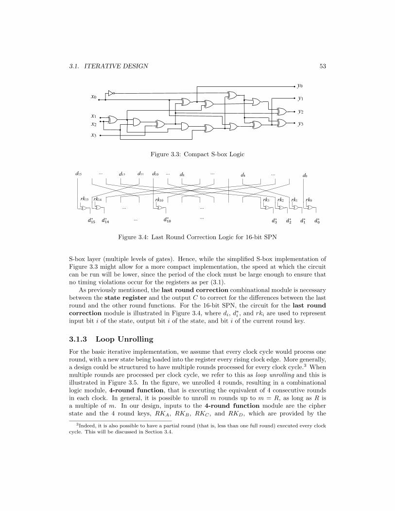
3.1. ITERATIVE DESIGN 53
y3
y1
y2
y0
x3
x2
x1
x0
Figure 3.3: Compact S-box Logic
d15 d11 d10 d4 d0 d12 d8
!"#∗ ... !"%∗ !&∗ !"∗ !'∗ !(∗ !"'∗
rk15
...
... ...
rk14 rk10
... rk2 rk3 rk1 rk0
... ...
...
Figure 3.4: Last Round Correction Logic for 16-bit SPN
S-box layer (multiple levels of gates). Hence, while the simplified S-box implementation ofFigure 3.3 might allow for a more compact implementation, the speed at which the circuitcan be run will be lower, since the period of the clock must be large enough to ensure thatno timing violations occur for the registers as per (3.1).
As previously mentioned, the last round correction combinational module is necessarybetween the state register and the output C to correct for the differences between the lastround and the other round functions. For the 16-bit SPN, the circuit for the last roundcorrection module is illustrated in Figure 3.4, where di, d
∗i , and rki are used to represent
input bit i of the state, output bit i of the state, and bit i of the current round key.
3.1.3 Loop Unrolling
For the basic iterative implementation, we assume that every clock cycle would process oneround, with a new state being loaded into the register every rising clock edge. More generally,a design could be structured to have multiple rounds processed for every clock cycle.3 Whenmultiple rounds are processed per clock cycle, we refer to this as loop unrolling and this isillustrated in Figure 3.5. In the figure, we unrolled 4 rounds, resulting in a combinationallogic module, 4-round function, that is executing the equivalent of 4 consecutive roundsin each clock. In general, it is possible to unroll m rounds up to m = R, as long as R isa multiple of m. In our design, inputs to the 4-round function module are the cipherstate and the 4 round keys, RKA, RKB , RKC , and RKD, which are provided by the
3Indeed, it is also possible to have a partial round (that is, less than one full round) executed every clockcycle. This will be discussed in Section 3.4.

54 CHAPTER 3. HARDWARE IMPLEMENTATION
RKE
state register
B
B B
B
B k
RKC
RKD
RKB
RKA
K_control
C_flag
sel P_flag 4-round
function
controller
key schedule
K P
K_flag
C
last round correction
Figure 3.5: Encryption with Loop Unrolling
key schedule module. As a result, the state register is loaded with the output of thecombinational logic needed to realize 4 rounds. The cipher states between every 4th roundprocessed during a clock cycle occur implicitly within the combinational logic and are neverstored in the register.
Since the round function combinational logic has 4 times as many levels as the 1-roundbasic iterative design, we would expect that the clock of the unrolled 4-round design wouldhave a period that is 4 times the period of the basic iterative design. In compensation,ciphertext is produced every R/4 clock cycles so that the throughtput is now given by4/(R · tclock) blocks/second, with the expectation that tclock is roughly 4 times larger thanfor the basic iterative design. In fact, it might be possible to decrease tclock to somethingless than 4 times that of the basic iterative design. Consider the timing constraint givenin (3.1). It is reasonable to expect tpd comb will be a little less than 4 times larger, since,although there are 4 layers of the round function operations, there is still only one layerof input multiplexer and tpd reg and tsetup will remain unchanged from the basic iterativedesign. Hence, if the timing values of the register, tpd reg and tsetup, and the propagationdelay through the multiplexer are not negligible, then the new tclock for the 4-round unrolleddesign could be significantly smaller than 4 times the 1-round basic iterative clock period.As a result, it might be possible to increase the speed of encryption by unrolling the iterativedesign.

3.2. PARALLELIZATION - A HIGH SPEED IMPLEMENTATION 55
B B
B B B k
C1
RK
round function
key schedule
K P1
Cm
round function
Pm
C2
round function
P2
state register state register state register
B
last round correction last round correction last round correction
Figure 3.6: Parallel Encryption (Datapath Only)
Although improvement in the speed of the cipher is possible with loop unrolling, itis difficult to predict whether such improvement will be significant, as it will be highlydependent on the target technology and the associated abilities of the design tools. However,it is clear that, since the combinational logic of 4 rounds (rather than one round) is requiredfor our design, we do expect that the area of the unrolled design will be substantially more.
3.2 Parallelization - A High Speed Implementation
An approach to hardware implementation that is of interest for high speed applications isthe concept of parallelization. In Figure 3.6, a parallelization method is used based on theunderlying structure of a basic iterative design. Note that, for simplicity, the diagram doesnot illustrate the controller module and any necessary control signals. The key scheduleand last round correction modules perform roles as previously described for the basiciterative architecture. The idea with parallelization is to replicate hardware so that theprocessing of multiple blocks can be undertaken concurrently. For example, in the figure,m blocks are processed by accepting simultaneously m plaintext blocks, P1 to Pm, into mdifferent datapaths. Within each datapath is an iterative design consisting of the hardwarefor one round and appropriate input selected by a multiplexer. Hence, each plaintext block isprocessed independently on the m different sets of hardware. After the appropriate numberof rounds, the output is made available for all ciphertexts as C1 to Cm as shown. Since miterative datapaths are happening concurrently, it is reasonable to assume that this designproduces ciphertext blocks at a speed that is m times the speed of the iterative design ofSection 3.1.1.
Obviously, there is a significant cost to parallelization in terms of the area of the resulting
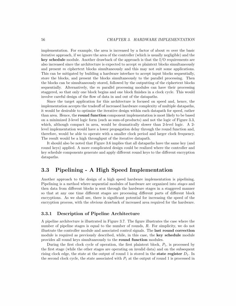
56 CHAPTER 3. HARDWARE IMPLEMENTATION
implementation. For example, the area is increased by a factor of about m over the basiciterative approach, if we ignore the area of the controller (which is usually negligible) and thekey schedule module. Another drawback of the approach is that the I/O requirements arealso increased since the architecture is expected to accept m plaintext blocks simultaneouslyand present m ciphertext blocks simultaneously and this may not suit some applications.This can be mitigated by building a hardware interface to accept input blocks sequentially,store the blocks, and present the blocks simultaneously to the parallel processing. Thenthe blocks can be simultaneously stored, followed by the outputting of the ciphertext blockssequentially. Alternatively, the m parallel processing modules can have their processingstaggered, so that only one block begins and one block finishes in a clock cycle. This wouldinvolve careful design of the flow of data in and out of the datapaths.
Since the target application for this architecture is focused on speed and, hence, theimplementation accepts the tradeoff of increased hardware complexity of multiple datapaths,it would be desirable to optimize the iterative design within each datapath for speed, ratherthan area. Hence, the round function component implementation is most likely to be basedon a minimized 2-level logic form (such as sum-of-products) and not the logic of Figure 3.3,which, although compact in area, would be dramatically slower than 2-level logic. A 2-level implementation would have a lower propagation delay through the round function and,therefore, would be able to operate with a smaller clock period and larger clock frequency.The result would be a high throughput of the iterative datapath.
It should also be noted that Figure 3.6 implies that all datapaths have the same key (andround keys) applied. A more complicated design could be realized where the controller andkey schedule components generate and apply different round keys to the different encryptiondatapaths.
3.3 Pipelining - A High Speed Implementation
Another approach to the design of a high speed hardware implementation is pipelining.Pipelining is a method where sequential modules of hardware are organized into stages andthen data from different blocks is sent through the hardware stages in a staggered mannerso that at any one time different stages are processing different parts of different blockencryptions. As we shall see, there is significant potential for increasing the speed of theencryption process, with the obvious drawback of increased area required for the hardware.
3.3.1 Description of Pipeline Architecture
A pipeline architecture is illustrated in Figure 3.7. The figure illustrates the case where thenumber of pipeline stages is equal to the number of rounds, R. For simplicity, we do notillustrate the controller module and associated control signals. The last round correctionmodule is required as previously described, while, in this case, the key schedule moduleprovides all round keys simultaneously to the round function modules.
During the first clock cycle of operation, the first plaintext block, P1, is processed bythe first stage (while the other stages are operating on invalid data) and on the subsequentrising clock edge, the state at the output of round 1 is stored in the state register D1. Inthe second clock cycle, the state associated with P1 at the output of round 1 is processed in

3.3. PIPELINING - A HIGH SPEED IMPLEMENTATION 57
state register DR
state register DR-1
stage 2 f2
state register D2
RKR+1 B
B
k
K state register D1
RKR
RKR-1
RK2
RK1 round function
key schedule
P
C
round function
round function
round function
last round correction
stage 1 f1
stage R-1 fR-1
stage R fR
g
Figure 3.7: Encryption Using Pipelining (Datapath Only)
the second stage hardware and stored in the register D2 at the output of this stage on thenext rising clock edge. Also, during this cycle, a second plaintext block, P2, is processed bythe first stage and stored in register D1 at the next clock edge. During the 3rd clock cycle,the 3rd stage processes data from P1, the 2nd stage processes data from P2, and now the 1ststage processes a third plaintext block P3. Data is stored in the associated 3 registers at thesubsequent rising clock edge. Note that during this time, the data in all the registers whichfollow stages not processing proper data is not meaningful and should be ignored. We referto the first R clock cycles as the period during which the pipeline is being primed and dataoutput C will not be valid while the pipeline is being primed.
After R clock cycles, the first plaintext has travelled through all R round functions andthe output data has now been loaded into the register following the last stage, DR, and,hence, is now available as ciphertext to the output (through the last round correctionmodule). In each subsequent clock cycle, the results from the following plaintexts are putinto the output register DR and presented as ciphertext. In other words, after the pipelineis primed, each clock cycle will produce one ciphertext. As data flows through the pipelinestages, the data of plaintext Pi will be followed by the data of plaintext Pi+1. Note that,although it takes R clock cycles for the original ciphertext to come out, once the pipelineis primed and all stages are processing legitimate data, ciphertext will be available everyclock cycle (assuming plaintext has been fed to the input in every clock cycle). Since thepropagation delay through the round function can be the same as for the round function ofthe basic iterative architecture, the speed at which the clock can be run is similar. However,

58 CHAPTER 3. HARDWARE IMPLEMENTATION
instead of producing a ciphertext block every R cycles, pipelining can produce a ciphertextblock every clock cycle. Hence, for this pipeline structure of one stage for every round,pipelining is R times faster than the basic iterative design and this comes at the expenseof roughly R times more area. Note that, although ciphertext can be produced every clockcycle, the latency of the system is still R clock periods, where we define latency to be thedelay from when a plaintext enters the system until when its ciphertext is produced at theoutput.
As with the parallel design, since pipelining is targeted to high speed applications, theround function hardware is best implemented as a low propagation delay 2-level logic circuit,thereby allowing for minimizing the period of the clock and maximizing the frequency of theclock. Note that, unlike other hardware architectures, a pipeline design has no feedback inthe circuit.
3.3.2 Selecting Hardware for a Pipeline Stage
Just as the basic iterative design can be unrolled, it is also possible to construct a pipelinearchitecture which has several consecutive rounds in a stage, rather than just one. Forexample, if R = 16, an 8 stage pipeline architecture could have 2 consecutive round functionsin one stage. (Registers would be placed between stages and not between rounds.) In thiscase, the pipeline will be processing 8 blocks simultaneously (but staggered) and, whenit is primed, a ciphertext block will be available every clock cycle. However, since theclock cycle must be long enough in duration to ensure that signals can flow through thecombinational logic of 2 rounds without creating any timing violations, the clock frequencyof the implementation will be lower than the pipeline architecture with 1 round per stage.
For some ciphers, it is possible to construct a pipeline architecture where a pipeline stagehas the logic of a partial round. For example, if a round is complex enough that it is possibleto slice the combinational logic of the round function into two halves (somewhat balancedin terms of their propagation delay) with a register between them, then a structure can beimplemented with 2R stages and it may be possible that the clock period can be cut roughlyin half. The result is an even faster implementation which produces a ciphertext block everyclock cycle, while processing data from 2R plaintext blocks simultaneously (but staggered) inthe pipeline. Since the round function of AES is somewhat complex using 8-bit S-boxes anda linear transformation (of ShiftRows and MixColumns) rather than a simple permutation,it is practical to break up the round function into different stages and this has lead to somevery fast architectures for AES [23]. For SPNs, like PRESENT, using 4-bit S-boxes, whichhave much smaller logic circuits in their realization of a round function, using stages whichprocess a partial round is less practical.
3.3.3 Timing Issues for Pipeline Designs
In general, there is limited value in breaking up rounds in an attempt to increase the numberof stages, increase the clock frequency, and increase the throughput of the cipher. Firstly,in breaking up round functions into stages, it is important to have each stage reasonablywell balanced in terms of the propagation delay, since the clock period must be as largeas the worst case propagation delay. For example, breaking down a round function with apropagation delay of tround into two stages, one with a propagation delay of 0.1× tround and
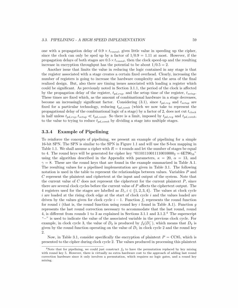
3.3. PIPELINING - A HIGH SPEED IMPLEMENTATION 59
one with a propagation delay of 0.9 × tround, gives little value in speeding up the cipher,since the clock can only be sped up by a factor of 1/0.9 = 1.11 at most. However, if thepropagation delays of both stages are 0.5× tround, then the clock speed-up and the resultingincrease in encryption throughput has the potential to be about 1/0.5 = 2.
Another issue that limits the value in reducing the logic contained in any stage is thatthe register associated with a stage creates a certain fixed overhead. Clearly, increasing thenumber of registers is going to increase the hardware complexity and the area of the finalrealized design. But, also there are timing issues associated with loading a register whichcould be significant. As previously noted in Section 3.1.1, the period of the clock is affectedby the propagation delay of the register, tpd reg, and the setup time of the register, tsetup.These times are fixed which, as the amount of combinational hardware in a stage decreases,become an increasingly significant factor. Considering (3.1), since tpd reg and tsetup arefixed for a particular technology, reducing tpd comb (which we now take to represent thepropagational delay of the combinational logic of a stage) by a factor of 2, does not cut tclockin half unless tpd reg, tsetup � tpd comb. So there is a limit, imposed by tpd reg and tpd comb,to the value to trying to reduce tpd comb by dividing a stage into multiple stages.
3.3.4 Example of Pipelining
To reinforce the concepts of pipelining, we present an example of pipelining for a simple16-bit SPN. The SPN is similar to the SPN in Figure 1.1 and will use the S-box mapping inTable 1.1. We shall assume a cipher with R = 4 rounds and let the number of stages be equalto 4. The round keys will be generated for cipher key “011011100111100100002 = 6E79016”using the algorithm described in the Appendix with parameters, κ = 20, α = 13, andγ = 8. These are the round keys that are found in the example summarized in Table A.1.The resulting values for a pipelined implementation are given in Table 3.1. The followingnotation is used in the table to represent the relationships between values. Variables P andC represent the plaintext and ciphertext at the input and output of the system. Note thatthe current value of C does not represent the ciphertext for the current plaintext P , sincethere are several clock cycles before the current value of P affects the ciphertext output. The4 registers used for the stages are labelled as Di, i ∈ {1, 2, 3, 4}. The values at clock cyclei are loaded at the rising clock edge at the start of clock cycle i and the values loaded aredriven by the values given for clock cycle i − 1. Function fi represents the round functionfor round i (that is, the round function using round key i found in Table A.1). Function grepresents the last round correction necessary to accommodate that the last round, round4, is different from rounds 1 to 3 as explained in Sections 3.1.1 and 3.1.2.4 The superscript“−” is used to indicate the value of the associated variable in the previous clock cycle. Forexample, in clock cycle 3, the value of D2 is produced by f2(D−1 ), which means that D2 isgiven by the round function operating on the value of D1 in clock cycle 2 and the round key2.
Now, in Table 3.1, consider specifically the encryption of plaintext P = CC85, which ispresented to the cipher during clock cycle 2. The values produced in processing this plaintext
4Note that for pipelining, we could just construct f4 to have the permutation replaced by key mixingwith round key 5. However, there is virtually no extra hardware cost to the approach of adding last roundcorrection hardware since it only involves a permutation, which requires no logic gates, and a round keymixing.

60 CHAPTER 3. HARDWARE IMPLEMENTATION
Clock P D1 D2 D3 D4 CCycle f1(P−) f2(D−1 ) f3(D−2 ) f4(D−3 ) g(D4)
0 DEBE XXXX XXXX XXXX XXXX XXXX1 BCA8 D701 XXXX XXXX XXXX XXXX2 CC85 0FEB C726 XXXX XXXX XXXX3 662A 8DE8 B0F2 C44A XXXX XXXX4 8D0B 9855 246E A1AF 584D 2AA35 083E 635E 00F7 EFFF E949 AB2F6 5728 F1C3 D877 30AF 81CF C2BF7 1E75 C5C9 8E87 7041 650D 6C2F8 D4D4 EF08 9A8B FC03 CC9C 8CA8
Table 3.1: Pipelining Example(All values in hexadecimal.)
are the values bolded in the table. At the clock edge at the end of clock cycle 2, the value8DE8 representing the output of round 1 for this plaintext is loaded into register D1 forclock cycle 3. At the next clock edge, value 246E, produced by round function f2, is loadedinto D2. Similarly, value EFFF is loaded into D3 for clock cycle 5 and then value 81CFis loaded into D4 for clock cycle 6. Recall this is output of the round function with keymixing (using round key 4), substitution, and permutation. Function g contains the inversepermutation (to negate the permutation of round function f4) and the key mixing of roundkey 5. The output of g is the value of cipertext C2BF, which is available in clock cycle 6,since there is no register in the last round correction hardware.
3.4 Serial Design - A Compact Implementation
Often the requirements of a hardware implementation demand that the cipher take up only asmall area of a device and this requirement often coincides with an expectation of low powerconsumption as well. Such compact implementations are necessary for applications such aswireless sensor nodes and some IoT devices. One typical method to minimize hardware areais to reduce the footprint caused by the most complex layer, substitution. Consider, forexample, an SPN based on the S-boxes of Table 1.1. A compact hardware realization of theS-box is illustrated in Figure 3.3, which uses only 14 2-input gates to implement the complete4-bit S-box, where the gates include inverters, ANDs, ORs, and XORs. This is equivalentto 3.5 gates per bit of the state. In comparison, the key mixing layer requires only 1 gateper state bit, an XOR of the data bit and round key bit, and the permutation layer involvesno gates, only wiring, to implement. The S-box complexity with 3.5 gates per bit is verylow and many other 4-bit S-boxes may not simplify to such a small number. Notably, whenlarge S-boxes are used, such as the 8-bit S-boxes of AES, there is a much larger number ofgates per bit. The most compact implementations of the AES S-box require about 250-300gates [24], which results in about 35 gates per bit.

3.4. SERIAL DESIGN - A COMPACT IMPLEMENTATION 61
3.4.1 The Concept of Serialization
One way to reduce the footprint of the substitution layer is to process a partial block or sub-block at one time, rather than the full B-bit block. We refer to this approach as serialization.Serialization presumes that every S-box mapping is the same and, hence, it is not necessaryto replicate the n-bit S-box hardware for every n-bit sub-block. For example, for the 64-bit SPN based on 4-bit S-boxes, the basic iterative approach processes a full block of 16S-boxes concurrently per clock cycle. However, using a serial design, the 64-bit SPN couldbe constructed to process a 16-bit sub-block per clock cycle, with 4 S-boxes being processedconcurrently. It would then take 4 clock cycles to process the 4 sub-blocks of a round.Hence, such a design is naturally going to produce ciphertext at a slower rate. For manyapplications, a lower throughput is an acceptable price to be paid for a smaller area and/orpower taken by the implementation of the cipher.
In the most extreme case of serialization, the 64-bit SPN could operate on a sub-block of4 bits (that is, one S-box) for each clock cycle. The resulting operation of a round would take16 clock cycles and, hence, such a design could be expected to be substantially slower thanthe basic iterative design and much slower than a high speed architecture like parallelizationor pipelining. Since this approach uses the smallest possible sub-block size in serialization(4 bits), we refer to this case as full serialization, while the previous example with a 16-bitsub-block size, we refer to as partial serialization.
3.4.2 A Sample Design
In order to explain thoroughly the concept of a serial design, we use as the basis for ourdiscussion, the full serialization of the 16-bit SPN, based on a 4-bit sub-block. A serialencryption architecture is shown in Figure 3.8. The concepts presented for this simpleexample can be extrapolated to more practical designs with larger block sizes and largerS-boxes. In the figure, there 3 general modules, the key schedule module, the controllermodule, and the datapath (including the S-box, selectable register, XOR gates, and themultiplexer). As in our discussions of the previous architectures, we will not discuss thekey schedule module except to note that we presume it provides the appropriate roundkey bits at the appropriate time. In this design, 4 bits of the round key, labelled RK, areto be provided to XOR with the state bits coming from the register and feeding into theS-box input. The controller is responsible for managing the input of the key and plaintextdata and controlling the flow of data in the datapath. The K flag and P flag signals areused by the external device to signal the input of the key K and plaintext block P . Thekey need only be loaded once for the subsequent processing of a large number of plaintextblocks. The controller also uses the 3-bit control signal, sel, to set the selection inputs ofthe register and the multiplexer at the output of the register.
Consider now the datapath. With the block size of 16 bits, it is necessary to have a16-bit register to store the cipher state. The 16-bit selectable register used to hold thestate has the ability to select from four inputs based on sel, including an input feeding fromthe plaintext input to the system, an input from the S-box output and two other internalinputs (not shown in Figure 3.8) which are fedback from bits within the register. The specialfeedback features of the selectable register and how sel could be used to select inputs willbe discussed in the next section.

62 CHAPTER 3. HARDWARE IMPLEMENTATION
2
3
sel
16
4
K_flag
4
4
4
4 4
4
4
4
4
4
16 S-box
RK
K_controlol
P_flag controller
key schedule
K
P
C_flag C
selectable register
Figure 3.8: Serial Encryption Design for 16-bit SPN
When the initial plaintext block is presented to the cipher, it is selected and loaded intothe register by the appropriate setting of sel. In the figure, the 16 bits of plaintext areloaded into the corresponding 16 bits of the register by dividing the 16-bit block into four 4-bit sub-blocks and feeding each sub-block into 4 bits of the register as shown. Subsequently,the cipher will process the substitution layer (as well as the key mixing layer) of the roundusing 4 clock cycles, where in one clock cycle the appropriate sub-block is selected by the4-bit multiplexer at the output of the register based on the sel signal provided by thecontroller. The sub-blocks will be selected sequentially, XORed with the 4 bits of roundkey coming from the key schedule module, fed through the S-box and into the register.The appropriate sub-block of the register will be updated with output from the S-box, whilethe other sub-blocks will remain unchanged based on the setting of the sel bits. Followingthe updating of the register based on the processing of 4 inputs to the S-box requiring 4clock cycles, the permutation layer of the S-box can be implemented using an appropriateselection of register output bits fedback into the appropriate register input bits (internal tothe register and not shown in Figure 3.8) and thus, in one clock cycle, the register bits canbe moved around based on the permutation wiring. As a result, with this design, 5 clockcycles are required to process a round. After the required number of R rounds, the registeroutput can be presented to the external device as the ciphertext indicated by control signalC flag. If we assume the propagation delay of the combinational logic of a round is similarto the expected propagation delay of the basic iterative block cipher (which is reasonable ifthe same logic realization is used for the S-box and ignoring the extra multiplexer delay), itcan be expected that it will take about 5 times longer to produce ciphertext for this serial

3.4. SERIAL DESIGN - A COMPACT IMPLEMENTATION 63
selectable register inside dashed box
00 01 10 11
4
4
sel0
sel1
4
4
d15 d11 d7 d3
from plaintext p15 p14 p13 p12
00 01 10 11
4
d15 d14 d13 d12
4
from S-box
sel2
from other register sub-blocks
sel0
sel1
´ 4
to S-box
to ciphertext c15 c14 c13 c12
Figure 3.9: Selectable Register Design (for Leftmost Sub-block)
design compared to the basic iterative design (assuming the register timing overheads areinsignificant).
Note that this design does not properly deal with the difference in the last round (wherethe permutation is replaced by a key mixing). The permutation is easy to reverse withsimple wiring of the inverse permutation between the register and the output C, but carefulmodification would need to be done to efficiently mix in bits from the last round key. Thiscould be done by adding a layer of key mixing at the S-box output, where in the firstR − 1 rounds, the post-S-box key bits mixed would be all zeroes and then in round R, thepost-S-box key bits mixed would be the last round key bits.
3.4.3 Selectable Register
To better understand the selectable nature of the register, consider Figure 3.9 which illustratesa potential design of the selection for the leftmost sub-block comprised of 4-bits of theregister, labelled as d15d14d13d12. Control signal sel from the controller in Figure 3.8can be implemented as a 3-bit signal (sel2sel1sel0) and used to control both the outputmultiplexer and the input multiplexers (one for each sub-block of 4 bits).
As shown in Figure 3.9, the input multiplexer selection bits are set to “10” to selectthe leftmost bits of the plaintext block, p15p14p13p12, when the register is initially loaded.The remaining 12 plaintext bits are loaded simultaneously into the remaining register bits.
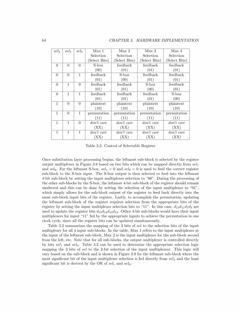
64 CHAPTER 3. HARDWARE IMPLEMENTATION
sel2 sel1 sel0 Mux 1 Mux 2 Mux 3 Mux 4Selection Selection Selection Selection
(Select Bits) (Select Bits) (Select Bits) (Select Bits)0 0 0 S-box feedback feedback feedback
(00) (01) (01) (01)0 0 1 feedback S-box feedback feedback
(01) (00) (01) (01)0 1 0 feedback feedback S-box feedback
(01) (01) (00) (01)0 1 1 feedback feedback feedback S-box
(01) (01) (01) (00)1 0 0 plaintext plaintext plaintext plaintext
(10) (10) (10) (10)1 0 1 permutation permutation permutation permutation
(11) (11) (11) (11)1 1 0 don’t care don’t care don’t care don’t care
(XX) (XX) (XX) (XX)1 1 1 don’t care don’t care don’t care don’t care
(XX) (XX) (XX) (XX)
Table 3.2: Control of Selectable Register
Once substitution layer processing begins, the leftmost sub-block is selected by the registeroutput multiplexer in Figure 3.8 based on two bits which can be mapped directly from sel1and sel0. For the leftmost S-box, sel1 = 0 and sel0 = 0 is used to feed the correct registersub-block to the S-box input. The S-box output is then selected to feed into the leftmost4-bit sub-block by setting the input multiplexer selection to “00”. During the processing ofthe other sub-blocks by the S-box, the leftmost 4-bit sub-block of the register should remainunaltered and this can be done by setting the selection of the input multiplexer to “01”,which simply allows for the sub-block output of the register to feed back directly into thesame sub-block input bits of the register. Lastly, to accomplish the permutation, updatingthe leftmost sub-block of the register requires selection from the appropriate bits of theregister by setting the input multiplexer selection bits to “11”. In this case, d15d11d7d3 areused to update the register bits d15d14d13d12. Other 4-bit sub-blocks would have their inputmultiplexers for input “11” fed by the appropriate inputs to achieve the permutation in oneclock cycle, since all the register bits can be updated simultaneously.
Table 3.2 summarizes the mapping of the 3 bits of sel to the selection bits of the inputmultiplexer for all 4 input sub-blocks. In the table, Mux 1 refers to the input multiplexer atthe input of the leftmost sub-block, Mux 2 is the input multiplexer for the sub-block secondfrom the left, etc. Note that for all sub-blocks, the output multiplexer is controlled directlyby bits sel1 and sel0. Table 3.2 can be used to determine the appropriate selection logicmapping the 3 bits of sel to the 2-bit selection of the input multiplexesr. This logic willvary based on the sub-block and is shown in Figure 3.9 for the leftmost sub-block where themost significant bit of the input multiplexer selection is fed directly from sel2 and the leastsignificant bit is derived by the OR of sel1 and sel0.

3.5. HARDWARE IMPLEMENTATION OF DECRYPTION 65
In practice, there is likely to be little gained by the serialization of the 16-bit SPN ofFigure 3.8. While the hardware required to implement multiple copies of the S-box has beenreduced, other hardware has been added in order to manage the appropriate flow of datain the datapath. For example, five 4-bit 4 × 1 multiplexers, one at the output and four atthe input of the register are required in a serial design, while, in the basic iterative design,one 16-bit 2× 1 multiplexer at the input is needed. Since the complexity of a 4-bit S-box isnot large, with only a few gates per bit, the complexity of serializing the design is not likelyto significantly decrease the area of the design and may even increase it. Also, the penaltyof slower operation is a definitive drawback to the architecture that may make any minorsaving in hardware not worthwhile for some applications. Serialization will have more valuefor ciphers with larger block sizes, such as a 64-bit SPN like PRESENT, and for ciphers suchas AES, which use large 8-bit S-boxes with a large area cost per bit for the S-box hardware.In such cases, reducing the number of S-box modules by serialization can result in muchmore significant savings than the cost of the necessary added multiplexers needed to controlthe flow of data in the serial design. Serial designs for PRESENT [25] and AES [26] havebeen proposed.
3.5 Hardware Implementation of Decryption
Our discussion of hardware implementation has focussed on encryption (or the forwarddirection) in the processing of data in a cipher. In an SPN, as previously noted, decryptioninvolves going in the reverse direction through the network and using the inverse components.Because the datapath for decryption is similar to the encryption datapath, generally, thesame architectures, from serial designs to pipeline designs, can be applied as appropriate forthe target application. We have already noted that the inverse key mixing is the same asthe forward key mixing and permutations can be used for which the inverse permutation isidentical to the forward permutation. This is the case for the SPNs in this article. In AES,however, the inverse linear transformation (specifically, the inverse MixColumns operation)is quite different than the forward operation [2]. Most significantly, for decryption the inverseS-boxes must be used in place of the S-box and this may be of consequence because of thepotentially large complexity. In some cipher proposals, S-boxes for which the forward andinverse mappings are the same are proposed. Such S-boxes are called involution S-boxesand can be found, for example, in the KLEIN cipher [27] and the Midori cipher [28]. Usinginvolution S-boxes allows the sharing of the S-box hardware between the encryption anddecryption structures. Such hardware re-use can reduce the overall area required by thecipher if both the encryption and decryption operations are required for an implementation.
One other significant aspect of decryption that may have influence on the design is theneed to apply the round keys in reverse order (that is, the round key of the last round inencryption is the first round key applied in decryption). This may be problematic for animplementation of decryption that wishes to use an on-the-fly approach to the key schedule.Since, typically, the only way to generate the last round key from encryption is to applythe full key schedule algorithm, the last round key state may need to be pre-computed.From this last key state, the key schedule can possibly proceed with an on-the-fly approachgoing backwards through the key schedule. Of course, in some applications, where plentifulmemory resources are available for the implementation, it may instead be desirable to simply
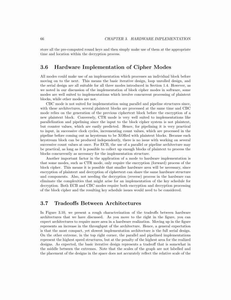
66 CHAPTER 3. HARDWARE IMPLEMENTATION
store all the pre-computed round keys and then simply make use of them at the appropriatetime and location within the decryption process.
3.6 Hardware Implementation of Cipher Modes
All modes could make use of an implementation which processes an individual block beforemoving on to the next. This means the basic iterative design, loop unrolled design, andthe serial design are all suitable for all three modes introduced in Section 1.4. However, aswe noted in our discussion of the implementation of block cipher modes in software, somemodes are well suited to implementations which involve concurrent processing of plaintextblocks, while other modes are not.
CBC mode is not suited for implementation using parallel and pipeline structures since,with these architectures, several plaintext blocks are processed at the same time and CBCmode relies on the generation of the previous ciphertext block before the encryption of anew plaintext block. Conversely, CTR mode is very well suited to implementations likeparallelization and pipelining since the input to the block cipher system is not plaintext,but counter values, which are easily predicted. Hence, for pipelining it is very practicalto input, in successive clock cycles, incrementing count values, which are processed in thepipeline before coming out as keystream to be XORed with plaintext blocks. Because eachkeystream block can be produced independently, there is no issue with working on severalsuccessive count values at once. For ECB, the use of a parallel or pipeline architecture maybe practical, as long as it is possible to collect up enough blocks of plaintext to process theblocks concurrently as necessary for the implementation structure.
Another important factor in the application of a mode to hardware implementation isthat some modes, such as CTR mode, only require the encryption (forward) process of theblock cipher. This means it is possible that smaller hardware area will be necessary, sinceencryption of plaintext and decryption of ciphertext can share the same hardware structureand components. Also, not needing the decryption (reverse) process in the hardware caneliminate the complexities that might arise for an implementation of the key schedule fordecryption. Both ECB and CBC modes require both encryption and decryption processingof the block cipher and the resulting key schedule issues would need to be considered.
3.7 Tradeoffs Between Architectures
In Figure 3.10, we present a rough characterization of the tradeoffs between hardwarearchitectures that we have discussed. As you move to the right in the figure, you canexpect architectures to require more area in a hardware realization. Moving up in the figurerepresents an increase in the throughput of the architecture. Hence, a general expectationis that the most compact, yet slowest implementation architecture is the full serial design.On the other extreme, in the top right corner, the parallel and pipelined implementationsrepresent the highest speed structures, but at the penalty of the highest area for the realizeddesigns. As expected, the basic iterative design represents a tradeoff that is somewhat inthe middle between the extremes. Note that the scales of the graph are not labelled andthe placement of the designs in the space does not accurately reflect the relative scale of the
3.7. TRADEOFFS BETWEEN ARCHITECTURES 67
parallel/pipeline
basic iterative
full serial
partial serial
increasing throughput
increasing area
Figure 3.10: Characterization of Architecture Tradeoffs
area and throughput. The figure is meant to be a rough characterization only. It does notinclude loop unrolling, which is likely to be slightly faster, but with significantly increasedarea over a basic iterative design. Also, the graph does not characterize the many levels ofparameterization that may occur for an architecture. For example, increasing the stages ina pipeline design will increase the area required and likely increase the throughput.
A more detailed comparison of the characteristics of the various hardware architecturesof a 64-bit SPN block cipher is given in Table 3.3. In the table, the throughput and arearequirements of the various architectures are considered. For simplicity in the comparison,the timing and area implications of any necessary multiplexers are not included. For amore precise comparison, since the various architectures have different requirements for themultiplexing of data, the effect of multiplexers should be considered.
The propagation delay through the combinational logic of the round function (specifically,the XOR gate of the key mixing and the logic of the S-box) is defined to be tfunc (inseconds) and, for simplicity, it is assumed that the S-box is the same implementation inall cases. For example, the S-boxes may be assumed to be a 2-level minimized AND-ORstructure. Of course, in practice, different architectures are likely to make use of differentS-box circuits: a high-speed implementation (such as pipelining) will probably use a lowdelay, 2-level structure for the S-box, while a compact implementation (such as a serialdesign) is likely to use a compact S-box structure (such as the one for the PRESENT S-boxin Figure 3.3) which may have a significantly larger propagation delay since more levels oflogic may be used. In more precise timing comparisons, differences between the propagationdelay through combinational hardware used in a round may occur due to the presence or

68 CHAPTER 3. HARDWARE IMPLEMENTATION
Architecture Minimum Throughput Combinational SequentialClock Period Area Area
(sec) (blocks/sec) (nm2) (nm2)Basic Iterative tfunc
1R·tfunc
Afunc Areg
Loop Unrolled ≤ 4 · tfunc ≥ 1R·tfunc
4 ·Afunc Areg(4 rounds)
Parallel tfuncm
R·tfuncm ·Afunc m ·Areg
(m Copies)Pipeline tfunc
1tfunc
R ·Afunc R ·Areg(R stages)Full Serial tfunc
116·R·tfunc
≥ 116 ·Afunc Areg
(1 4-bit S-box)Partial Serial tfunc
14·R·tfunc
≥ 14Afunc Areg
(4 4-bit S-boxes)
Table 3.3: Hardware Tradeoffs for R-Round 64-bit SPN(Ignoring effects of multiplexers.)
absence of multiplexers in the datapath. As well, it is possible the minimum clock period isalso significantly affected by the propagation delay of the register and the setup time of theregister, but this is not considered in the table.
In the table, the variable Afunc represents the area requirement (in nanometers squared)of the combinational logic of the round function consisting of 16 parallel 4-bit S-boxes and theXOR gates of the key mixing layer. Although we do not consider it, in some architectures,the presence or absence of multiplexers affects the area required in a round. Again, itis assumed that one type of S-box implementation is used in the comparison across thearchitectures. The variable Areg represents the area required for the implementation ofa 64-bit register. Note that the area requirements of the key schedule module and thecontroller are not considered in the analysis. In most cases, it is probably reasonable toassume that the controller area is negligible compared to the datapath. However, dependingon the implementation structure, which is affected by the details of the key schedulingalgorithm, the key schedule module could require a significant amount of hardware area(although not likely as much as the cipher datapath) and/or a large amount of registermemory (perhaps significantly more than the datapath if the round keys are pre-computedand stored). These issues are not considered in the comparison presented in the table. Inthe table, the cipher is assumed to have R rounds and, for the parallel implementation, ageneral number, m, of parallel implementations are considered.
In Table 3.3, the nominal design can be considered to be the basic iterative design with aclock period of tfunc (ignoring the register timings), resulting in a throughput of 1/(R ·tfunc)blocks/sec, and areas of Afunc and Areg for the combinational logic of the round functionand the register used to store the state, respectively.
For the unrolled architecture, the propagation delay must be at least tfunc but is certainly≤ 4 · tfunc for 4 unrolled rounds. In practice, the delay may be less than 4 times the delay ofthe 1-round basic iterative architecture, since the delay due to the multiplexer at the input

3.8. SUMMARY 69
of the combinational hardware only affects the round hardware once (not 4 times) and theregister timing values are possibly not negligible as discussed in Section 3.1.3. This results ina throughput which is at least as large as the throughput for the basic iterative architecture,but it may be larger if these timing factors are significant. So the unrolled architecture maybe an improvement on the speed of the basic iterative design, but will certainly have a largercombinational logic area requirement, while having the same area needed for sequential logicregisters.
Both the parallel and pipelined structures can improve the speed of encryption byoperating on multiple blocks simultaneously. For the parallel structure, if the I/O interfaceallows as many as m simultaneous inputs and outputs, then a corresponding speed-up occursin the throughput and a corresponding increase in the area costs occur. For pipelining, withthe number of stages equal to R, the throughput and area increases by a factor of roughly R.For R stages, the I/O can be structured to present and receive one plaintext and ciphertextblock each clock cycle. This can be adjusted to structures with fewer than R stages withcorresponding effects on the throughput and area. Since there are no multiplexers nowin the round hardware, in practice, the clock could be marginally faster than for the basiciterative design. As well, if a pipelining architecture can split one round into multiple stages,there will be a corresponding increase in throughput and the area as the number of stagesincrease. It should be noted that, as previously discussed in Section 3.3.3, as the numberof stages increase, the propagation delay through the combinational logic will decrease andthe register propagation delay and setup time might become significant.
Lastly, the serial implementation decreases the throughput by a factor of at least thenumber of clock cycles to finish a round. Because multiplexers are required at both theinput and output of the register, the effect on the combinational logic propagation delaycould be significant (although this is not reflected in the table). Further, the combinationalarea is reduced by possibly as much as the same factor, although practically, this is notlikely since the reduced S-box hardware area will be offset by extra multiplexer circuitry tocontrol data flow. It should be noted that the sequential logic area still requires as manybits as are needed to store the state. Hence, no reduction in register bits can occur fromthe basic iterative architecture. Note also that the decrease in throughput should actuallyhave a factor equal to “block size / sub-block size + 1” (that is, one greater than the valuein the table) if the strategy used is the same as the sample hardware design discussed inSection 3.4 which required one more clock cycle in a round to complete the permutation.For example, using this approach, the full serialization for 64-bit SPN with 4-bit S-boxestakes 17, not 16, clock cycles to complete a round.
3.8 Summary
In this chapter, we have discussed different architectures for implementing SPN block ciphersin a synchronous, sequential logic design targeted to common hardware technologies likeFPGAs and CMOS ASICs. The most basic approach would be an iterative design usingthe round structure of the cipher to guide the architecture. To improve cipher thoughput,parallelization and pipelining are discussed as options. As well, serialization is presented asmethod that could be used to decrease the area requirement of a cipher implementation. Forall architectures, sample designs are used to illustrate the concepts. The chapter also briefly

70 CHAPTER 3. HARDWARE IMPLEMENTATION
discusses issues associated with the implementation of decryption and the three block ciphermodes introduced in Section 1.4. To wrap up the discussion, a brief overview of the tradeoffsthat exist between the various implementation strategies is discussed. It should be notedthat comprehensive introduction to block cipher hardware implementation architectures,with a focus on AES, can be found in Chapters 10-12 of [29].

Chapter 4
Conclusion
In this article, we have presented a tutorial on several basic implementation strategies ofblock ciphers. Our implementations span software applications, where we discuss tablelookup approaches and bit-slicing, to hardware applications, where we describe basic iterativeapproaches, as well as high-speed designs like pipelining, and compact designs involvingserialization. For the basis of our descriptions, we have used the basic SPN as the modelcipher. This represents a practical structure found in many proposed ciphers and is thefoundation for the most applied block cipher, AES. However, many distinct implementationstructures are proposed for different ciphers and such considerations must be made for anycipher targeted for implementation. AES, in particular, has been extremely well studiedand discussed for its software and hardware implementation approaches and the reader isencouraged to investigate further many of the clever implementation approaches applied toAES.
Finally, it should be noted that a very important consideration for the implementationof ciphers is the notion of resistance to side channel analysis (SCA) attacks [30]. SCAattacks are a category of attacks that take advantage of implementation characteristics torelate side-channel information to the cipher key. Side-channel information exploited inattacks includes power traces, timing of encryption, and response to injected faults, as wellas others. All implementations should be aware of and mitigate the susceptibility of a systemto leakage of information due to side channels. This is an extremely rich area of research,with many hundreds of papers published. Alas, we choose to leave this discussion to others,but encourage all cipher implementers to pursue these issues, once their knowledge of thebasic implementation structures discussed in this article is solidified.
71

72 CHAPTER 4. CONCLUSION

References
[1] National Institute of Standards and Technology. NIST SpecialPublication 197: Advanced Encryption Standard (AES), November 2001.csrc.nist.gov/publications/detail/fips/197/final.
[2] Joan Daemen and Vincent Rijmen. The Design of Rijndael: AES - The AdvancedEncryption Standard. Information Security and Cryptography. Springer, 2002.
[3] Alex Biryukov and Leo Perrin. State of the art in lightweight symmetric cryptography.IACR Cryptology ePrint Archive, 2017:511, 2017.
[4] Shay Gueron. Intel’s new AES instructions for enhanced performance and security. InOrr Dunkelman, editor, Fast Software Encryption, 16th International Workshop, FSE2009, Leuven, Belgium, February 22-25, 2009, Revised Selected Papers, volume 5665 ofLecture Notes in Computer Science, pages 51–66. Springer, 2009.
[5] Akashi Satoh, Sumio Morioka, Kohji Takano, and Seiji Munetoh. A compact rijndaelhardware architecture with s-box optimization. In Colin Boyd, editor, Advances inCryptology - ASIACRYPT 2001, 7th International Conference on the Theory andApplication of Cryptology and Information Security, Gold Coast, Australia, December9-13, 2001, Proceedings, volume 2248 of Lecture Notes in Computer Science, pages239–254. Springer, 2001.
[6] Andrey Bogdanov, Lars R. Knudsen, Gregor Leander, Christof Paar, Axel Poschmann,Matthew J. B. Robshaw, Yannick Seurin, and C. Vikkelsoe. PRESENT: anultra-lightweight block cipher. In Pascal Paillier and Ingrid Verbauwhede, editors,Cryptographic Hardware and Embedded Systems - CHES 2007, 9th InternationalWorkshop, Vienna, Austria, September 10-13, 2007, Proceedings, volume 4727 ofLecture Notes in Computer Science, pages 450–466. Springer, 2007.
[7] Claude E. Shannon. Communication theory of secrecy systems. Bell Syst. Tech. J.,28(4):656–715, 1949.
[8] U.S. Department of Commerce. National Bureau of Standards Federal InformationProcessing Standard 46: Data Encryption Standard (DES), January 1977.
[9] Mitsuru Matsui. Linear cryptanalysis method for DES cipher. In Tor Helleseth, editor,Advances in Cryptology - EUROCRYPT ’93, Workshop on the Theory and Application
73

74 REFERENCES
of of Cryptographic Techniques, Lofthus, Norway, May 23-27, 1993, Proceedings, volume765 of Lecture Notes in Computer Science, pages 386–397. Springer, 1993.
[10] Eli Biham and Adi Shamir. Differential cryptanalysis of des-like cryptosystems. InAlfred Menezes and Scott A. Vanstone, editors, Advances in Cryptology - CRYPTO’90, 10th Annual International Cryptology Conference, Santa Barbara, California, USA,August 11-15, 1990, Proceedings, volume 537 of Lecture Notes in Computer Science,pages 2–21. Springer, 1990.
[11] International Organization for Standardization. ISO/IEC 29192-2:2019 Informationsecurity — Lightweight cryptography — Part 2: Block ciphers, November 2019. availableat iso.org.
[12] National Institute of Standards and Technology. NIST Special Publication 800-38A: Recommendation for Block Cipher Modes of Operation, December 2001.crsc.nist.gov/publications/detail/sp/800-38a/final.
[13] Ryad Benadjila, Jian Guo, Victor Lomne, and Thomas Peyrin. Implementinglightweight block ciphers on x86 architectures. In Tanja Lange, Kristin E. Lauter, andPetr Lisonek, editors, Selected Areas in Cryptography - SAC 2013 - 20th InternationalConference, Burnaby, BC, Canada, August 14-16, 2013, Revised Selected Papers,volume 8282 of Lecture Notes in Computer Science, pages 324–351. Springer, 2013.
[14] Eli Biham. A fast new DES implementation in software. In Eli Biham, editor, FastSoftware Encryption, 4th International Workshop, FSE ’97, Haifa, Israel, January 20-22, 1997, Proceedings, volume 1267 of Lecture Notes in Computer Science, pages 260–272. Springer, 1997.
[15] Kostas Papapagiannopoulos. High throughput in slices: The case of present, PRINCEand KATAN64 ciphers. In Nitesh Saxena and Ahmad-Reza Sadeghi, editors, RadioFrequency Identification: Security and Privacy Issues - 10th International Workshop,RFIDSec 2014, Oxford, UK, July 21-23, 2014, Revised Selected Papers, volume 8651 ofLecture Notes in Computer Science, pages 137–155. Springer, 2014.
[16] Mitsuru Matsui and Junko Nakajima. On the power of bitslice implementation onintel core2 processor. In Pascal Paillier and Ingrid Verbauwhede, editors, CryptographicHardware and Embedded Systems - CHES 2007, 9th International Workshop, Vienna,Austria, September 10-13, 2007, Proceedings, volume 4727 of Lecture Notes in ComputerScience, pages 121–134. Springer, 2007.
[17] Seiichi Matsuda and Shiho Moriai. Lightweight cryptography for the cloud: Exploit thepower of bitslice implementation. In Emmanuel Prouff and Patrick Schaumont, editors,Cryptographic Hardware and Embedded Systems - CHES 2012 - 14th InternationalWorkshop, Leuven, Belgium, September 9-12, 2012. Proceedings, volume 7428 of LectureNotes in Computer Science, pages 408–425. Springer, 2012.
[18] Ross Anderson, Eli Biham, and Lars Knudsen. Serpent: A Proposal for the AdvancedEncryption Standard. National Institute of Science and Technology, January 1998.

REFERENCES 75
[19] Wentao Zhang, Zhenzhen Bao, Dongdai Lin, Vincent Rijmen, Bohan Yang, and IngridVerbauwhede. RECTANGLE: A bit-slice ultra-lightweight block cipher suitable formultiple platforms. IACR Cryptol. ePrint Arch., 2014:84, 2014.
[20] Vincent Grosso, Gaetan Leurent, Francois-Xavier Standaert, and Kerem Varici. Ls-designs: Bitslice encryption for efficient masked software implementations. In CarlosCid and Christian Rechberger, editors, Fast Software Encryption - 21st InternationalWorkshop, FSE 2014, London, UK, March 3-5, 2014. Revised Selected Papers, volume8540 of Lecture Notes in Computer Science, pages 18–37. Springer, 2014.
[21] Emilia Kasper and Peter Schwabe. Faster and timing-attack resistant AES-GCM.In Christophe Clavier and Kris Gaj, editors, Cryptographic Hardware and EmbeddedSystems - CHES 2009, 11th International Workshop, Lausanne, Switzerland, September6-9, 2009, Proceedings, volume 5747 of Lecture Notes in Computer Science, pages 1–17.Springer, 2009.
[22] Mike Hamburg. Accelerating AES with vector permute instructions. In ChristopheClavier and Kris Gaj, editors, Cryptographic Hardware and Embedded Systems - CHES2009, 11th International Workshop, Lausanne, Switzerland, September 6-9, 2009,Proceedings, volume 5747 of Lecture Notes in Computer Science, pages 18–32. Springer,2009.
[23] Alireza Hodjat and Ingrid Verbauwhede. Area-throughput trade-offs for fully pipelined30 to 70 gbits/s AES processors. IEEE Trans. Computers, 55(4):366–372, 2006.
[24] David Canright. A very compact s-box for AES. In Josyula R. Rao and Berk Sunar,editors, Cryptographic Hardware and Embedded Systems - CHES 2005, 7th InternationalWorkshop, Edinburgh, UK, August 29 - September 1, 2005, Proceedings, volume 3659of Lecture Notes in Computer Science, pages 441–455. Springer, 2005.
[25] Carsten Rolfes, Axel Poschmann, Gregor Leander, and Christof Paar. Ultra-lightweightimplementations for smart devices - security for 1000 gate equivalents. In GillesGrimaud and Francois-Xavier Standaert, editors, Smart Card Research and AdvancedApplications, 8th IFIP WG 8.8/11.2 International Conference, CARDIS 2008, London,UK, September 8-11, 2008. Proceedings, volume 5189 of Lecture Notes in ComputerScience, pages 89–103. Springer, 2008.
[26] M. Feldhofer, J. Wolkerstorfer, and V. Rijmen. Aes implementation on a grain of sand.IEE Proceedings - Information Security, 152(1):13–20, Oct 2005.
[27] Zheng Gong, Svetla Nikova, and Yee Wei Law. KLEIN: A new family of lightweightblock ciphers. In Ari Juels and Christof Paar, editors, RFID. Security and Privacy -7th International Workshop, RFIDSec 2011, Amherst, USA, June 26-28, 2011, RevisedSelected Papers, volume 7055 of Lecture Notes in Computer Science, pages 1–18.Springer, 2011.
[28] Subhadeep Banik, Andrey Bogdanov, Takanori Isobe, Kyoji Shibutani, HarunagaHiwatari, Toru Akishita, and Francesco Regazzoni. Midori: A block cipher for lowenergy. In Tetsu Iwata and Jung Hee Cheon, editors, Advances in Cryptology -
76 REFERENCES
ASIACRYPT 2015 - 21st International Conference on the Theory and Application ofCryptology and Information Security, Auckland, New Zealand, November 29 - December3, 2015, Proceedings, Part II, volume 9453 of Lecture Notes in Computer Science, pages411–436. Springer, 2015.
[29] Cetin Kaya Koc, editor. Cryptographic Engineering. Springer, 2009.
[30] Francois-Xavier Standaert. Introduction to side-channel attacks. In Ingrid M. R.Verbauwhede, editor, Secure Integrated Circuits and Systems, Integrated Circuits andSystems, pages 27–42. Springer, 2010.
[31] Eli Biham. New types of cryptanalytic attacks using related keys. J. Cryptology,7(4):229–246, 1994.
[32] Celine Blondeau and Benoıt Gerard. Links between theoretical and effective differentialprobabilities: Experiments on PRESENT. IACR Cryptology ePrint Archive, 2010:261,2010.

Appendix: Key Scheduling
Generalization of the PRESENT Key Schedule
In the main body of this article, we have described the data flow associated with the plaintextto ciphertext processing and only alluded to the key schedule which is responsible for thegeneration of round keys from the original cipher key. Key scheduling algorithms tend tobe uniquely defined for each proposed cipher and, hence, it is harder to identify a generalstructure that represents the concepts typically found in a key schedule. So, here, we describethe key scheduling algorithm in PRESENT, but generalize to various sizes of parameters.
Consider a cipher key K = kκ−1kκ−2...k1k0 of size κ bits, used for an SPN cipher with ablock size of B bits and n-bit S-boxes. It is assumed that κ ≥ B. Let K ′ = k′κ−1k
′κ−2...k
′1k′0
represent the key state bits that are processed during the key schedule. Let R represent thenumber of rounds and assume that R < 32 and, hence, the round number can be representedin binary by 5 bits.1 To represent the round number, we use variable r, referred to as theround count, where the 5 bits of r are given by [r4r3r2r1r0]. Variable α represents a rotationalvalue used during the key schedule. A typical key schedule (derived from the PRESENTkey schedule), illustrated in Figure A.1, might consist of the following steps:
1. Let r = 1 and assign the bits of cipher key K to key state K ′:
[k′κ−1k′κ−2...k
′1k′0]← [kκ−1kκ−2...k1k0]
2. If r > R+ 1, then stop.
3. Use the leftmost B bits of K ′, [k′κ−1k′κ−2...k
′κ−B+1k
′κ−B ] as round key, RKr.
4. Update K ′ as follows:
(a) Rotate K ′ left by α positions:
[k′κ−1k′κ−2...k
′1k′0]← [k′κ−α−1k
′κ−α−2...k
′κ−α+1k
′κ−α]
(b) Process the leftmost n bits with the n-bit S-box:
[k′κ−1k′κ−2...k
′κ−n]← S(k′κ−1, k
′κ−2, ..., k
′κ−n)
1The limit of 32 rounds is a reasonable limit satisfied by practical ciphers. However, it is a trivial matterto extend the size of the round count to more bits if necessary.
77

78 REFERENCES
load cipher key into key register
XOR round count
!!" !!#$" !!#%" !!#&" !!#'"
!(#$" !(#%" . . . !)"
take leftmost B bits as
round key, RK
repeat until all round keys
generated
apply S-box to leftmost n bits
cipher key
state output Z
rotate left by a
v1 v0 v15v14v13v12v11v10v9 v8 v7 v6 v5 v4 v3 v2
r4 r3 r2 r1r0
!(#$!(#%. . . !)
!(#$" !(#%" . . . !)"
!(#$" !(#%" . . . !)"
$(!(#$" . . . !(#*" )
Figure A.1: Sample Key Schedule Structure
(c) XOR the round count into round key bits from position γ down to γ − 4:
[k′γk′γ−1k
′γ−2k
′γ−3k
′γ−4]
← [k′γk′γ−1k
′γ−2k
′γ−3k
′γ−4]⊕ [r4r3r2r1r0]
5. Increment r and return to step 2.
Note that operation “⊕” represents the bitwise XOR operation and S(·) represents the S-boxmapping.
For the version of the PRESENT cipher with an 80-bit key, κ = 80, B = 64, n = 4,R = 31, α = 61, and γ = 19. Overall this key schedule derives informational content ina balanced way from all cipher key bits, mixes in a complex nonlinear operation on thebits through the S-box, and ensures that each round has a distinct operation by adding aconstant derived from the round number (thereby preventing attacks such as related keysattacks [31]).
In Table A.1, we present an example of the key schedule for a simple 16-bit SPN. TheSPN is similar to the SPN in Figure 1.1 and uses the S-box mapping in Table 1.1. Weassume that there are R = 4 rounds and, therefore, 5 round keys must be generated. Theround keys for the system will be generated for 20-bit cipher key 011011100111100100002(6E79016) using the algorithm described above with parameters, κ = 20, α = 13, and γ = 8.
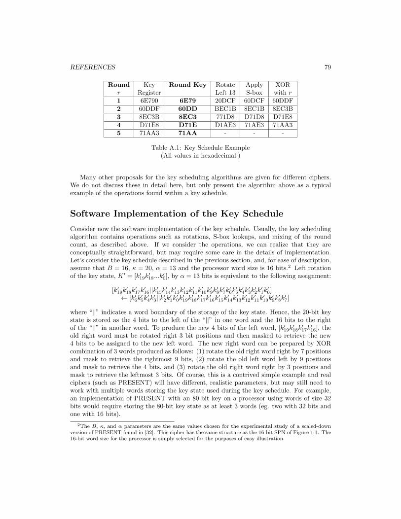
REFERENCES 79
Round Key Round Key Rotate Apply XORr Register Left 13 S-box with r1 6E790 6E79 20DCF 60DCF 60DDF2 60DDF 60DD BEC1B 8EC1B 8EC3B3 8EC3B 8EC3 771D8 D71D8 D71E84 D71E8 D71E D1AE3 71AE3 71AA35 71AA3 71AA - - -
Table A.1: Key Schedule Example(All values in hexadecimal.)
Many other proposals for the key scheduling algorithms are given for different ciphers.We do not discuss these in detail here, but only present the algorithm above as a typicalexample of the operations found within a key schedule.
Software Implementation of the Key Schedule
Consider now the software implementation of the key schedule. Usually, the key schedulingalgorithm contains operations such as rotations, S-box lookups, and mixing of the roundcount, as described above. If we consider the operations, we can realize that they areconceptually straightforward, but may require some care in the details of implementation.Let’s consider the key schedule described in the previous section, and, for ease of description,assume that B = 16, κ = 20, α = 13 and the processor word size is 16 bits.2 Left rotationof the key state, K ′ = [k′19k
′18...k
′0], by α = 13 bits is equivalent to the following assignment:
[k′19k′18k′17k′16||k′15k′14k′13k′12k′11k′10k′9k′8k′7k′6k′5k′4k′3k′2k′1k′0]
← [k′6k′5k′4k′3||k′2k′1k′0k′19k′18k′17k′16k′15k′14k′13k′12k′11k′10k′9k′8k′7]
where “||” indicates a word boundary of the storage of the key state. Hence, the 20-bit keystate is stored as the 4 bits to the left of the “||” in one word and the 16 bits to the rightof the “||” in another word. To produce the new 4 bits of the left word, [k′19k
′18k′17k′16], the
old right word must be rotated right 3 bit positions and then masked to retrieve the new4 bits to be assigned to the new left word. The new right word can be prepared by XORcombination of 3 words produced as follows: (1) rotate the old right word right by 7 positionsand mask to retrieve the rightmost 9 bits, (2) rotate the old left word left by 9 positionsand mask to retrieve the 4 bits, and (3) rotate the old right word right by 3 positions andmask to retrieve the leftmost 3 bits. Of course, this is a contrived simple example and realciphers (such as PRESENT) will have different, realistic parameters, but may still need towork with multiple words storing the key state used during the key schedule. For example,an implementation of PRESENT with an 80-bit key on a processor using words of size 32bits would require storing the 80-bit key state as at least 3 words (eg. two with 32 bits andone with 16 bits).
2The B, κ, and α parameters are the same values chosen for the experimental study of a scaled-downversion of PRESENT found in [32]. This cipher has the same structure as the 16-bit SPN of Figure 1.1. The16-bit word size for the processor is simply selected for the purposes of easy illustration.
80 REFERENCES
For the implementation of the S-box, a table lookup approach can be easily used.Appropriate shifting and masking must be used to prepare the index for the lookup andto move the result into the appropriate position within the words used to store the keystate. The mixing (i.e., XOR) of the round count is also straightforward to realize usingappropriate masking. For example, for the key schedule parameters for the 16-bit SPN aboveand assuming that the key state bits to be XORed with the round count to be [k′8k
′7k′6k′5k′4],
the XOR of the round count with the key state can be achieved as follows:
[k′15k′14k′13k′12k′11k′10k′9k′8k′7k′6k′5k′4k′3k′2k′1k′0]⊕ [0000000r4r3r2r1r00000]
where r4r3r2r1r0 are the bits of the round count r.
Hardware Implementation of Key Schedule
In our discussion of the various architectures that could be employed for the hardwareimplementation of block ciphers, we did not deal with the hardware necessary to implementthe key schedule. The key schedule for different ciphers can vary quite dramatically, but if weconsider the sample key schedule previously described, we can conclude that the necessarystructure should be somewhat simpler than the datapath processing the cipher state. Forexample, the operations involved in the key schedule include storage of key state (generallythe same size as the original cipher key), the application of one S-box mapping per round,the XOR of the round count value, and the rearrangement of the bit positions within thekey register. These are not difficult to implement and, for an iterative design, will not takeup much area in the targeted technology.
The most significant decision to be made for the implementation of the key schedule iswhether to use (1) a round key setup approach, which pre-computes and stores all roundkeys prior to processing any plaintext data, or (2) an on-the-fly round key generationapproach, where the key schedule is applied concurrently with the round function of thecipher datapath. These are the two approaches highlighted in Figures 1.7 and 1.8. Unlikein software implementations, where there is small cost of the memory necessary for storingall round keys for subsequent use during data processing, in hardware implementations,storing a full set of round keys (in registers or in possibly on-board RAM in an FPGA)would typically add dramatically to the resource and area requirement for the design. Forexample, an implementation of the 64-bit SPN PRESENT key schedule which stores allround keys would require (R+ 1) ·B = 32 · 64 = 2048 bits, which dwarfs the requirement of64 register bits to store the state needed in a basic iterative implementation. For this reason,most hardware implementations are more likely to choose an on-the-fly approach to the keyschedule. Such an approach can generate the round keys concurrently with the round dataprocessing and, hence, is likely to have little impact on the cipher throughput.