A TURBULENT STRUCTURE OF GAS-DROPLETS EVAPORATING DOWNWARD SPRAY
7
ILASS 2008 Sep. 8-10, 2008, Como Lake, Italy INTRODUCTION The evaporation of atomised liquid in a turbulent jet flows is used in a number of processes in the power engineering, chemical and food industries, in combustion apparatuses and evaporators, agricultural spraying, spray drying, spray cooling, spray painting, spray casting, and spray scrubbers for gas cleaning and particle separation. The effect of droplets on the intensity on the turbulent flow field structure and turbulent transport processes becomes more higher with increase of droplets size and its mass concentration. These phenomenon influence on heat and mass transfer and determine the flow field structure. For the optimization of evaporation or combustion processes is necessary to know a information about the flow structure, phases velocity fluctuations and droplets size distributions. Therefore, the development of mathematical models of gas-droplets flow is a topical problem in hydrodynamics, heat and mass transfer two-phase flow theory. The present study is focused on low velocity turbulent and steady sprays, which are for example relevant for spray cooling and spray drying and is aiming at the development of a numerical model for predicting sprays based on the Eulerian/Eulerian approach. Investigations of evaporating spray are a prerequisite for further study of spray combustion. The comprehensive reviews of spray with evaporation or combustion can be found in, e.g. [1-4]. Several numerical and experimental studies of the droplet evaporation process in gas-droplets flows are presently available, reported by [5-10] Almost all authors used the Eulerian/Lagrangian approach in their numerical studies. The exceptions here are the studies by Mostafa and Mongia [6], and by Zuev and Lepeshinsky [8]. In the present work was numerically examined the structure of the gas-droplets flow with and without droplet evaporation. The computational model was based on the Eulerian/Eulerian approach for the gas and dispersed phases. NUMERICAL MODEL Statement of the problem In our study, we addressed the problem about a developing two-phase gas-droplet jet. A schematic of the gas-droplets spray flow is shown in Fig. 1. The volume concentration of the dispersed phase was assumed low ( <10 -4 ), and the particles, fine (d<200 µm). According to data reported by [11], the collisions between particles could be neglected when considering the heat and mass transfer processes and hydrodynamics in the two-phase jet flow. j j U 6J x d 2 /3 1 8 i j j i T i i j j i L i Li D L L u i j j UU U P k U x x x x x U U C U U J g uu x Pr Pr i T PL L L i i T i V PL L ut T PV PA j i i P j UT C T T T x x x K C g T D C C ut x x C x A TURBULENT STRUCTURE OF GAS-DROPLETS EVAPORATING DOWNWARD SPRAY V. Terekhov, M. Pakhomov Kutateladze Institute of Thermophysics Siberian Branch of Russian Academy of Sciences, Lab. of Thermal and Gas Dynamics, 630090, Acad. Lavrent'ev Avenue,1, Novosibirsk, Russia E-mails: [email protected], [email protected] ABSTRACT This paper deals with the computational study of droplets evaporation in the turbulent round jet. The Eulerian/Eulerian model was employed for spray computation wherein the gas turbulence was modeled using the LRN k- model. The model is based on solving a system of Reynolds-averaged Navier-Stokes equations for the two-phase flow. The fluctuating dispersed phase characteristics were calculated assuming models previously used by Zaichik et al. (1997), and Derevich (2002). In the present study it was examined the influence of main parameters of two-phase flow, such as droplet diameter, droplet concentration, and gas-phase temperature, on the droplet evaporation process and on the flow structure in the two-phase gas-droplet jet flow. The axial gas velocity declines more slowly with a growth of droplets mass concentration in comparison with a one-phase jet. Increase in mass concentration of droplets results in contraction of two-phase gas-droplets jet. Here, the dispersed phase acts to decrease the gas turbulence level, this influence becoming more pronounced with increase in the droplet concentration. Paper ID ILASS08-14-3 1
Transcript of A TURBULENT STRUCTURE OF GAS-DROPLETS EVAPORATING DOWNWARD SPRAY

ILASS 2008
Sep. 8-10, 2008, Como Lake, Italy
Paper ID ILASS08-082
INTRODUCTION
The evaporation of atomised liquid in a turbulent jet flows is used in a number of processes in the power engineering, chemical and food industries, in combustion apparatuses and evaporators, agricultural spraying, spray drying, spray cooling, spray painting, spray casting, and spray scrubbers for gas cleaning and particle separation. The effect of droplets on the intensity on the turbulent flow field structure and turbulent transport processes becomes more higher with increase of droplets size and its mass concentration. These phenomenon influence on heat and mass transfer and determine the flow field structure. For the optimization of evaporation or combustion processes is necessary to know a information about the flow structure, phases velocity fluctuations and droplets size distributions. Therefore, the development of mathematical models of gas-droplets flow is a topical problem in hydrodynamics, heat and mass transfer two-phase flow theory. The present study is focused on low velocity turbulent and steady sprays, which are for example relevant for spray cooling and spray drying and is aiming at the development of a numerical model for predicting sprays based on the Eulerian/Eulerian approach.
Investigations of evaporating spray are a prerequisite for further study of spray combustion. The comprehensive reviews of spray with evaporation or combustion can be found in, e.g. [1-4]. Several numerical and experimental studies of the droplet evaporation process in gas-droplets flows are presently available, reported by [5-10] Almost all authors used the Eulerian/Lagrangian approach in their numerical studies. The exceptions here are the studies by Mostafa and Mongia [6], and by Zuev and Lepeshinsky [8].
In the present work was numerically examined the structure of the gas-droplets flow with and without droplet evaporation. The computational model was based on the Eulerian/Eulerian approach for the gas and dispersed phases.
NUMERICAL MODEL
Statement of the problem
In our study, we addressed the problem about a developing two-phase gas-droplet jet. A schematic of the gas-droplets spray flow is shown in Fig. 1. The volume concentration of the dispersed phase was assumed low ( <10-4), and the particles, fine (d<200 µm). According to data reported by [11], the collisions between particles could be neglected when considering the heat and mass transfer processes and hydrodynamics in the two-phase jet flow.
j
j
U 6J
x d
2 / 3
1
8
i j ji
T
i i j j i
Li Li D L L u i j
j
U U UP k U
x x x x x
U U C U U J g u ux
Pr Pr
i T PL LL
i i T i
V PL L ut
T PV PA j
i i P j
U T CTT T
x x x
K C gTD C C u t
x x C x
A TURBULENT STRUCTURE OF GAS-DROPLETS
EVAPORATING DOWNWARD SPRAY
V. Terekhov, M. Pakhomov
Kutateladze Institute of Thermophysics Siberian Branch of Russian Academy of Sciences, Lab. of Thermal and Gas Dynamics,
630090, Acad. Lavrent'ev Avenue,1, Novosibirsk, Russia E-mails: [email protected], [email protected]
ABSTRACTThis paper deals with the computational study of droplets evaporation in the turbulent round jet. The Eulerian/Eulerian model
was employed for spray computation wherein the gas turbulence was modeled using the LRN k- model. The model is based
on solving a system of Reynolds-averaged Navier-Stokes equations for the two-phase flow. The fluctuating dispersed phase characteristics were calculated assuming models previously used by Zaichik et al. (1997), and Derevich (2002). In the present study it was examined the influence of main parameters of two-phase flow, such as droplet diameter, droplet concentration, and gas-phase temperature, on the droplet evaporation process and on the flow structure in the two-phase gas-droplet jet flow. The axial gas velocity declines more slowly with a growth of droplets mass concentration in comparison with a one-phase jet. Increase in mass concentration of droplets results in contraction of two-phase gas-droplets jet. Here, the dispersed phase acts to decrease the gas turbulence level, this influence becoming more pronounced with increase in the droplet concentration.
Paper ID ILASS08-14-3
1

6
Sc Sc
i V VT
i i T i
U K K J
x x x d
/P RT.
The turbulent Reynolds stresses and the turbulent heat and mass fluxes in the gas phase were determined according to the Boussinesq hypothesis; they have the form
2
3
ji
i j T ij
j i
UUu u k
x x,
Pr
Tj
T j
Tu t
x,
Sc
VTj V
T j
Ku k
x
Here, ij is the Kronecker delta, and T is the turbulent dynamic viscosity.
LRN two-equations turbulence model
Gas phase turbulence was described with LRN k- model
by Hwang and Lin [12]. The model was modified to the case of evaporating droplets. The empirical constants of the turbulence model take on their values of Hwang and Lin [12]. The adoption of the Taylor microscale in the damping functions and the inclusion of pressure diffusion terms in both
the k and equations were key features of this model.
It is known [13] that calculation with application of
ordinary constants in the k model provides exaggerate
results (approximately 20 30%) for the process of jet
expansion. With a rise of C 1/C 2 ratio expansion of a round
jet decreases. An increase in only constant C 1 drags out jet degeneration. With the purpose of correction, the following
constant modifications of the k model [12], shown in [13],
were used:
C =0.09-0.04f C 2=1.92-0.067f, where 0.2
1/ 2 0 0
02
r U Uf
U x x,
here r1/2 jet half-width estimated on the gas phase velocity U=0.5U1.
Dispersed phase
The system of averaged equations governing transport processes in the dispersed phase has the form
6Lj
j
U J
x d
2
1
Lj Li Li LjL Li
L L
j j j j
LijLi Li L
j
U U u uU
x x x x
DU U g
x
2
Pr
LL
Lj L L LjL
L L
j j j j
PL LL
P
TU T u
x x x x
CT T
C
Here, / 3L u T Lf k is the turbulent kinematic dispersed
phase viscosity written similarly to [11]; fu is the coefficient of particle entrainment in intense vortex motion;
= Ld2/(18 W) and 2 /(12 )pL LC d Y are the particle
dynamic and thermal relaxation times written with regard for the deviation from the Stokes law;
2 / 31 Re / 6LW , 1/ 2 1/ 31 0.3Re PrLY ; kL is the turbulent
kinetic dispersed-phase energy given by the relation 2 2 2
1
2 2L iL L L
i
k u u v ; DLij is the turbulent
diffusion tensor of the particles. The turbulent heat flux in dispersed phase has the form [11,14]
1
21 1 LL Lj v j Lj
j
Tu f u t u
x,
where f v is the function determined the entrainment of particles into intense fluctuations of gas phase velocity and temperature.
The system of dispersed phase velocity and temperature r.m.s. fluctuations based on model by [14]. The heat and mass transfer model for a single droplet was described in detail see of Terekhov and Pakhomov [15].
NUMERICAL SOLUTION ALGORITHM AND TEST
CALCULATIONS FOR ONE-PHASE AIR JET
At the axis of the jet flow the conditions of zero momentum and energy fluxes for the gas and dispersed phases were set. At the outer boundary flow quantities in the low-velocity co-current gas stream were specified. The turbulence kinetic energy and the gradient of the dissipation rate of this energy were both zero. In calculating the two-phase jet flow, inlet conditions were set at the nozzle exit plane either as uniform profiles of phase characteristics or as distributions preliminarily calculated for a two-phase pipe flow. At the exit cross-section boundary conditions were set in the form of zero derivatives of varied quantities.
The discretization of the transport equations in the computational domain was performed by using finite-volume approach. The QUICK scheme [16] used for convective fluxes. The diffusion terms in the momentum, energy and vapor concentration equations were approximated by second-order central difference which gives the stable solution. The SIMPLEC solution algorithm [17] was adopted for pressure-velocity coupling.
Fig. 1. The scheme of the two-phase jet. 1 – jet nozzle, 2 –gas-droplets jet.
2

In axial and radial directions, a logarifmically non-uniform calculation grid was used. All calculations were performed on the grid with 200×100 nodal points. Further increase in the number of calculation nodes caused no substantial changes in the calculated data.
Numerical model was tested by comparison with experimental results for one-phase air round jet by Panchapakesan and Lumley [18].
THE COMPARISON WITH EXPERIMENTAL AND
NUMERICAL RESULTS FOR GAS-PARTICLE JET
WITHOUT HEAT TRANSFER
Figures 2 3 illustrate the evolution of dispersed-phase characteristics over the jet length for the experimental conditions used by Prevost et al. [19] and for the conditions adopted in the numerical study by Derevich [14]. The experimental data were obtained with the help of a phase
Doppler anemometer. The particle diameter was d=10 15
µm, 20 25 µm, 30 35 µm, 40 45 µm; the dispersed phase material, glass of density P=2990 kg/m3; the mass concentration of the particles, MP=0.08; the gas flow Reynolds number, Re=13100; the nozzle diameter, 2R=10mm, and the gas velocity at the nozzle exit plane, U1=20 m/s. The flow moved in the downward direction. In numerical study [14] used the Eulerian/Eulerian approach in the boundary layer approximation.
The distributions of longitudinal dispersed phase velocity across the jet flow for various particle sizes are shown in Fig. 2. An increase in the dispersed phase diameter leads to increased velocity of particles compared to the single-phase flow. The latter regularity can be distinctly traced in the experimental data by [19], in the numerical data by [14], and in the present calculation data.
Figure 3 shows the axial and radial velocity fluctuations of the two phases at the distance x/(2R)=20 from the nozzle exit (Figs. 3a and 3b, respectively). The dispersed phase is seen to exert a pronounced effect on the structure of the fluctuating jet flow. An analysis of the experimental data by Prevost et al. [19], data calculated by Derevich [14], and the present calculation data point to the fact that turbulent fluctuations are quite anisotropic. The amplitude of the longitudinal pulsations of particle velocity over the jet axis and over the transverse coordinate is higher than the amplitude of similar fluctuations in the single-phase jet flow. This phenomenon can be attributed to the additional production of particle-induced turbulence due to turbulent migration and due to the action of the spatially non-uniform mean dispersed phase velocity.
The transverse pulsations of dispersed phase velocity along the axis and over the cross-section of the jet flow are smaller than the gas velocity fluctuations. With increase in the particle size the fluctuations of dispersed phase velocity weaken. The latter can be explained by less pronounced entrainment of particles into the fluctuating gas motion observed with increase in the dispersed phase size. The particles are less entrained into the large scale gas motion, and they therefore take less energy from the carrier phase turbulent eddies. The reduced intensity of transverse gas phase fluctuations leads to weaker pulsations of small sized particles.
It is seen that the present calculation data for the two-phase jet flow well agree with the data by Prevost et al. [19] and Derevich [14].
COMPUTATIONS OF EVAPORATING SPRAY AND
ITS DISCUSSIONS
The calculated heat and mass transfer data for the gas-droplet jet flow with phase transitions are shown in Fig. 4 6.Here, the gas-droplet jet emanates from a nozzle whose diameter is 2R=20 mm. The gas-flow velocity at the nozzle exit plane is U1=30 m/s, and the gas-phase Reynolds number
is Re=2RU1/ =4×10⁴. The initial droplet diameter was varied
in the range d1=1 200 µm, the mass concentration of the
Fig. 2. Radial profiles of gas and particles velocity atx/(2R)=20. Points are experimental data by [19], filled
symbols are two-phase jet, open symbols are one-phase gas jet: 1 – d=0 µm; 2 – 10–15 µm; 3 – 40–45 µm,
dashed curves are computations by [14], solid curves are our numerical data: 1 – d=0 µm; 2 – 15 µm; 3 – 45 µm.
a
bFig. 3. The distribution of axial (a) and radial (b) gas and particles fluctuations at x/(2R)=20. The designations and
conditions are the same as in Figure 2.
3
droplets was ML1=0 20 %, and the dispersed phase
droplets was ML1=0 20 %, and the dispersed phase velocity
was UL1=0 30 m/s. The gas-flow temperature was varied in
the interval T1=303 373 K, the droplet temperature was TL1=293 K, and the ambient temperature at the outer boundary of the jet flow was Te=303 K.
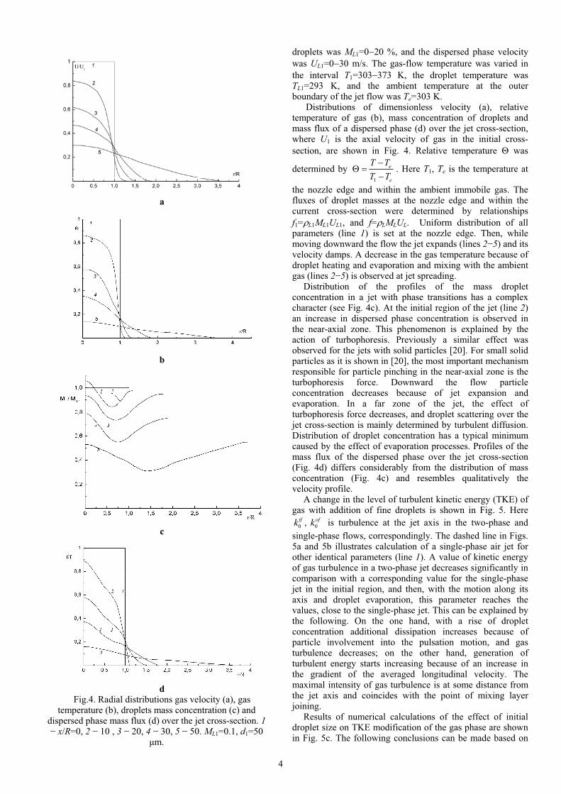
Distributions of dimensionless velocity (a), relative temperature of gas (b), mass concentration of droplets and mass flux of a dispersed phase (d) over the jet cross-section, where U1 is the axial velocity of gas in the initial cross-
section, are shown in Fig. 4. Relative temperature was
determined by 1
e
e
T T
T T. Here T1, Te is the temperature at
the nozzle edge and within the ambient immobile gas. The fluxes of droplet masses at the nozzle edge and within the current cross-section were determined by relationships
f1= L1ML1UL1, and f= LMLUL. Uniform distribution of all parameters (line 1) is set at the nozzle edge. Then, while moving downward the flow the jet expands (lines 2 5) and its velocity damps. A decrease in the gas temperature because of droplet heating and evaporation and mixing with the ambient gas (lines 2 5) is observed at jet spreading.
Distribution of the profiles of the mass droplet concentration in a jet with phase transitions has a complex character (see Fig. 4c). At the initial region of the jet (line 2)an increase in dispersed phase concentration is observed in the near-axial zone. This phenomenon is explained by the action of turbophoresis. Previously a similar effect was observed for the jets with solid particles [20]. For small solid particles as it is shown in [20], the most important mechanism responsible for particle pinching in the near-axial zone is the turbophoresis force. Downward the flow particle concentration decreases because of jet expansion and evaporation. In a far zone of the jet, the effect of turbophoresis force decreases, and droplet scattering over the jet cross-section is mainly determined by turbulent diffusion. Distribution of droplet concentration has a typical minimum caused by the effect of evaporation processes. Profiles of the mass flux of the dispersed phase over the jet cross-section (Fig. 4d) differs considerably from the distribution of mass concentration (Fig. 4 ) and resembles qualitatively the velocity profile.
A change in the level of turbulent kinetic energy (TKE) of gas with addition of fine droplets is shown in Fig. 5. Here
0 0,tf ofk k is turbulence at the jet axis in the two-phase and
single-phase flows, correspondingly. The dashed line in Figs. 5a and 5b illustrates calculation of a single-phase air jet for other identical parameters (line 1). A value of kinetic energy of gas turbulence in a two-phase jet decreases significantly in comparison with a corresponding value for the single-phase jet in the initial region, and then, with the motion along its axis and droplet evaporation, this parameter reaches the values, close to the single-phase jet. This can be explained by the following. On the one hand, with a rise of droplet concentration additional dissipation increases because of particle involvement into the pulsation motion, and gas turbulence decreases; on the other hand, generation of turbulent energy starts increasing because of an increase in the gradient of the averaged longitudinal velocity. The maximal intensity of gas turbulence is at some distance from the jet axis and coincides with the point of mixing layer joining.
Results of numerical calculations of the effect of initial droplet size on TKE modification of the gas phase are shown in Fig. 5c. The following conclusions can be made based on
a
b
c
dFig.4. Radial distributions gas velocity (a), gas
temperature (b), droplets mass concentration (c) and dispersed phase mass flux (d) over the jet cross-section. 1
x/R=0, 2 10 , 3 20, 4 30, 5 50. ML1=0.1, d1=50µm.
4

analysis of Fig. 5c. There is a range of particles sizes, corresponding to maximal suppression of TKE level
(approximately 100 200 µm). The following increase in the particle size provides a gradual increase in gas turbulence because of its generation at streamlining of large droplets. In the range of initial region of the jet (line 1) turbulence suppression is maximal and reaches 80 %. After mixing layer joining of the single-phase jet (the length of initial region is x/R 6), a drastic increase in TKE level is observed, whereas, in the two-phase jet the length of initial region is x/R>6, and it increases with a rise of initial size of droplets (see Fig. 5a). Downward the flow from the point of mixing layer joining
(lines 2 4) the value of TKE suppression reaches 30 40 %. For the cross-section very far from the nozzle edge (line 5),
where the effect of evaporating droplets is low, turbulence suppression is 10 %.
THE COMPARISON WITH EXPERIMENTAL AND
NUMERICAL RESULTS FOR EVAPORATING
SPRAYS
Subsequent figures compare our computations with the experimental data by Solomon et al. [5], and numerical results of Mostafa and Mongia [6] and by Berlemont et al. [7].
The predicted and measured gas-phase velocities over the length of the jet are shown in Fig. 6. The measured data, which were reported by [5], were obtained by the LDA method. The mass concentration of Freon-11 droplets was ML1=7.71, and the droplet size was d1=31 µm. The initial gas temperature and the initial ambient temperature were T1=263K, and the saturation point of Freon droplets was TL1=240.3K. The initial diameter of the air jet was 2R=1.194 mm, and the initial gas velocity was U1=64.5 m/s. The measurements were performed at the following distances from the nozzle exit plane: x/(2R)=50, 100, 250, and 500. Figure 10 also compares the shown data with the numerical calculations by [6]. The calculations by Mostafa and Mongia [6] were performed using the Eulerian/Lagrangian approach and the Eulerian/Eulerian approach for gas and dispesed phases. The gas velocity is seen to decrease along the jet flow. In both approaches, a system of transport equations in the boundary
a
b
cFig. 5. Profiles of gas phase turbulent kinetic energy
(TKE) (a) along the jet length cross-section,(b) over jet, (c) – modification of TKE in two-phase spray. 1d1=10 µm, 2 50 µm, 3 100 µm. x/R=30, ML1=0.1.
Fig. 6. Profiles of axial gas velocity along the jet axis. Symbols are measurements by [5], curves are
predictions: dashed curves are the numerical results of
[6]: 1 Euleraian approach, 2 Lagrangian approach; solid curve is the calculation by this paper.
Fig. 7. Profiles of turbulent kinetic energy along the jet radius. Symbols are experiment [5], dashed curves are
computations [6]: 1 – eulerian/lagrangian approach; 2 – eulerian/eulerian approach, solid curve is the results of
our paper (curve 3). x/(2R)=250.
5

layer approximation is used. In the Fig. 7 was shown the profiles of turbulent kinetic
energy (TKE) across the jet radius. Calculations was provided by Mostafa and Mongia [5] with using eulerian/lagrangian and eulerian/eulerian models in boundary layer approach. The loci of maximum of TKE is approximate confirm to the point of closure of shear layers.
The distribution of gas temperature along the axis of the jet flow is shown in Fig. 8. The solid curves show the temperatures calculated by the present model, and the dashed curves, the calculated data of [7]. Here, the mass concentration of droplets is ML1=0.5, and the droplet size is d1=100 µm. The initial gas temperature and the initial ambient temperature are T1=400 K, and the initial droplet temperature is TL1=300 K. The initial diameter of the air jet is 2R=20 mm; the initial diameter of the dispersed phase flow, 16 mm; the gas-flow velocity at the nozzle exit plane, U1=28 m/s; and the initial velocity of the particles, UL1=0.7U1=19.6 m/s. The fields of velocity pulsations for the phases at the nozzle exit plane were identical. An abrupt initial decrease in the gas temperature is seen, resulting from the heating and evaporation of methanol droplets. As the jet flow gets heated due to mixing with the hot ambient air and due to particle size reduction, an increase of the gas temperature is observed. A good general agreement between the temperature distributions till the distance from the nozzle x/(2R)=40 deserves mention.
Father downstream, typical of the calculated data by Berlemont et al. [7] is a decrease in the gas temperature, whereas our data exhibit a smooth rise of gas temperature up to the ambient temperature, equal to Te=400 K.
Cross-section profiles of dispersed phase diameter are presented in the Fig. 9, where d1 is the initial size of droplets. The size of dispersed phase decreases due to evaporation while moving along the jet length. In the distance from the jet axis zone, the droplet diameter decreases also due to a process of jet mixing with a hot immobile ambient medium. We can observe that the smaller droplets there are on the jet edges. This behavior is more pronounced as they move downstream region from the jet nozzle holder. In the Fig. 9 we can see that it was obtained a good agreement between our data and numerical results by Berlemont et al. [7].
It is observed that the present numerical model for the two-phase jet with droplets evaporation well agree with the numerical and experimental data.
CONCLUSIONS
It is shown for the two-phase jet flows with droplet evaporation that amplitude of axial turbulent velocity fluctuations of the disperse phase is significantly higher than that of radial ones. This phenomenon is connected not only with intrinsic non-isotropic character of turbulent pulsations of the dispersed phase, but also with additional generation of turbulence at dispersed phase motion in the gradient field of the averaged axial velocity of the dispersed phase. Intensity of particle velocity pulsations in the axial direction is higher than in the single-phase gas jet under the same other conditions. Intensity of radial fluctuations of the dispersed phase velocity is significantly less than the value of single-phase pulsations along the whole jet.
Results of calculations and measurements for the case of the two-phase jet were compared. Other works on distribution of parameters of the two-phase evaporating jet along its axis and over the cross-section demonstrate satisfactory correlation of calculation and measurement results with variation of initial parameters in a wide alteration range.
ACKNOWLEDGEMENTS
This work was partially supported by the Russian Foundation for Basic Research (projects no. 05-02-16281, 05-08-33586, and 06-08-00967) and Russian Federation’s Presidental Foundation (Grant MK-186.2007.8).
NOMENCLATURE
CD coefficient of resistance
p, CpA, CpL, CpV heat capacities of mixture, air, liquid, and vapor (J(kg K)-1)D vapor diffusion coefficient in air (m2 s-1)DxL, DrL turbulent diffusivities of droplets in the axial and radial directions due to the stochastic motion of droplets and its entrainment into the gas flow by intense vortices (m2 s-1)d droplet or particle diameter (m) J steam mass flux from the surface of evaporating droplet (kg m-2 s-1)L heat of vaporization (J kg-1)k turbulent kinetic energy (m2 s-2)ML droplet mass concentration in the triple air-vapor- droplet mixture P pressure (Nm-2)
Fig. 8. The distributions of the gas centerline temperature along the two-phase jet. Dashed curve is the predictions of [7] calculations (ML1=0.5), solid curve is
the calculation by this paper.
Fig. 9. Radial distributions of droplets size. Dashed curves are numerical calculations by [7], solid curves are
calculations by this paper. 1 – x=0.2 m; 2 – 0.5 m; 3 – 1 m.
6

r1/2 jet half-width estimated on the gas phase velocity U=0.5U1.R nozzle exit radius (m) U, V velocity component in axial and radial directions (ms-1)
temperature (K) x, r axial and radial coordinates (m)
2 2,u v r.m.s. velocity fluctuations in axial and radial
directions (m2s-2)Pr Prandtl number Sc Schmidt number Re Reynolds number
Greek
volume concentration of droplets
production of turbulent kinetic energy (kg s-3 m)
relative temperature
heat transfer coefficient (W m-2 K-1)
dissipation rate (m2 s-3)
dynamic viscosity (N s m-2)
kinematic viscosity (m2 s-1)
density (kg m-3)
particle relaxation time (s)
particle thermal relaxation time (s)
Subscripts0 parameter on the jet axis 1 parameter at the jet nozzle exit A air L droplet P particle
turbulent parameter V vapor e parameter in the ambient medium.
REFERENCES
[1] N.A. Chigier, The Atomization and Burning of Liquid Fuel Sprays, Prog. Eng. Combust. Sci., vol. 9, pp. 1-76, 1976.
[2] G.M. Faeth, Mixing, Transport and Combustion in Ssprays, Prog. Eng. Combust. Sci., vol. 13, pp. 293-345, 1987.
[3] W.A. Sirignano, Fluid Dynamics of Sprays – 1992 Freeman Scholar Lecture, Trans. ASME J. Fluid Eng.,vol. 115, pp. 345-378, 1992.
[4] F. Peng and S.K. Aggarwal, A Review of Droplets Dynamics and Vaporization Modeling for Engineering Calculation, Trans. ASME J. Eng. Gas Turbines & Power, vol. 117, pp. 453-461, 1995.
[5] A.S.P. Solomon, J.-S. Shuen, Q.-F. Zhang and G.M. Faeth, Measurements and Predictions of the Structure Evaporating Sprays, Trans ASME J. Heat Transfer, vol. 107, pp. 679-686, 1985.
[6] A.A. Mostafa and H.C. Mongia, On the Modeling Turbulent Evaporation Jets: Eulerian Versus
Lagrangian Approach. Int. J. Heat Mass Transfer, vol. 30, pp. 2583-2593, 1987.
[7] A. Berlemont, M.-S. Grancher and G. Gousbet, Heat and Mass Coupling between Vaporizing Droplets and Turbulence using Lagrangian Approach, Int. J. Heat Mass Transfer, vol. 38, pp. 3023-3034, 1995.
[8] Yu.V. Zuev and I.A. Lepeshinsky, Two-Phase Multi-component Turbulent Jet with Phase Canges, FluidDynamics, vol. 30, pp. 130-137, 1995.
[9] X.-Q. Chen and J.C.F. Pereira, Computation of Turbulent Evaporating Sprays with Well-Specified Measurements: A Sensitive Study on droplet Properties, Int. J. Heat Mass Transfer, vol. 39, pp. 441-454, 1996.
[10] M. Sommerfeld, Analysis of Isothermal and Evaporating Turbulent Sprays by Phase-Doppler Anemometry and Numerical Calculations, Int. J. Heat Fluid Flow, vol. 19, pp. 173-186, 1998.
[11] L.I. Zaichik, V.A. Pershukov, M.V. Kozelev and A.A. Vinberg, Modeling of Dynamics, Heat Transfer, and Combustion in Two-Phase Turbulent Flow: 1. Isothermal Flow, Int. J. Exp. Thermal Fluid Sci., vol. 15, pp. 291-310, 1997.
[12] C.B. Hwang and C.A. Lin, Improved Low-Reynolds-
Number k– Model Based on Direct Simulation Data,
AIAA J., vol. 36, pp. 38-43, 1998. [13] T.-W. Kuo and F.V. Bracco, On the Scaling of
Impulsively Started Incompressible Turbulent Round Jet, Trans. ASME J. Fluid Eng., vol. 104, pp. 191-197, 1982.
[14] I.V. Derevich, The Hydrodynamics and Heat Transfer and Mass Transfer of Particles Under Conditions of Turbulent Flow of Gas Suspension in a Pipe and in an Axisymmetric Jet, High Temp., vol. 40, pp. 78-91, 2002..
[15] V.I. Terekhov and M.A. Pakhomov, The Thermal Efficiency of Near-Wall Gas-Droplets Screens. I. Numerical Modeling, Int. J. Heat Mass Transfer, vol. 48, pp. 1747-1759, 2005.
[16] B.P. Leonard, A Stable and Accurate Convective Modelling Procedure Based on Quadratic Upstream Interpolation, Comput. Methods Appl. Mech. Eng., vol. 19, pp. 59-98, 1979.
[17] J.P. Van Doormaal and G.D. Raithby, Enhancements of the SIMPLE Method for Predicting Incompressible Fluid Flow. Int. J. Numerical Heat Transfer, vol. 7, pp. 147-163, 1984.
[18] N.R. Panchapakesan and J.L. Lumley, Turbulence Measurements in Axisimmetric Jet of Air and Helium. Part. 1. Air Jet, J. Fluid Mech., vol. 246, pp. 197-223, 1993
[19] F. Prevost, J. Boree, H.J. Nuglish and G.Charnay, Measurements of Fluid/Particle Correlated Motion in the Far Field of an Axisymmetric Jet, Int. J. Multiphase Flow, vol. 22, pp. 685-701, 1996.
[20] A.A. Shraiber, L.B. Gavin, V.A. Naumov and V.P. Yatsenko, Turbulent Flows of Gas Suspensions, Hemisphere, New York, 1990.
7