A TRANSISTOR HEARING AID - Philips Bound... · 130 PHILlPS TECHNICAL REVIEW VOLUME 19 A TRANSISTOR...
10
130 PHILlPS TECHNICAL REVIEW VOLUME 19 A TRANSISTOR HEARING AID by P. BLOM. and P. BOXMAN. Some time 'ago a short report appeared in this Review on the transistor, hearing-aid type KL 5500. A more detailed description ofthis apparatus illustrates clearly the great advantages resulting from the use of transistors. The entry of the transistor into electronic engin- eering has opened up entirely new possibilities. The most outstanding advantages of the transistor over thermionic valves are its small dimensions and low power consumption, the latter mainly because no filament current is required. Moreover, the power can he supplied by a source of very low voltage. This is particularly advantageous where the source consists of dry batteries, since the energy (the number of watt hours) is supplied much more cheaply by a battery of a few volts than by a battery of some tens of volts. Furthermore, practice has already shown that, in general, transistors may be expected to have a longer life than valves. . Small dimensions and low battery costs are points of especial importance where hearing aids are con- cerned. It is not surprising, therefore, that the first practical application of transistors on a large scale has been in hearing aids, particularly since what is required is amplification at audio frequencies and relatively low power outputs, which is precisely the field of application for which transistors were first manufactured on a commercial basis. The transistors in question are nevertheless capable of supplying a higher output power than is economically possible with the subminiature valves used in valve hearing aids. Transistors offer certain other advantages which make them particularly suitable for hearing aids. In th~ circuit with a common emitter, which is the circuit mostly employed at low frequencies, the impedances involved are relatively low 1). Even in a very compact construction there is therefore nothing to fear from stray capacitance coupling: the stray capacitances form high impedances carrying neglig- ible currents. What is more, transistors' show no microphonic effect; the measures normally needed 1) For the three principle transistor configurations, viz. the circuits with common emitter, common base and common collector, and for a survey of some of their fundamental properties, see for example J. P. Beijersbergen, M. Beun and J. te Winkel, The junction transistor as a network element at low frequencies, 1. Characteristics and h param- eters, Philips tecb. Rev. 19, 15-27, 1957/58 (No. I). 621.395.92: 621.375.4 to combat this effect can therefore be dispensed with, which again makes for compactness. With the Philips transistor hearing aid described here (type KL 5500) 2), the aim has been to help the largest possible number of users. Accordingly this is still the hearing aid with the ,ridest field of applica- tion. Two other types are also being manufactured: type KL 5600, which corresponds substantially to KL 5500 but is smaller (with the sacrifice of some of its possibilities and entailing higher battery costs) and the even smaller type KL 5700, which is in a certain sense a de luxe model, combining minimum dimensions with high quality. Infig.l the three hear- ing aids are shown side by side. Requirements to be satisfied by a hearing aid Speech intelligibility, which is of course the most important criterion for the usefulness of a hearing aid, is a problem which has been solved in modern instruments to the satisfaction of a wide circle of the hard of hearing. Although new measures to improve speech Intelligibility are continually being developed - particularly as regards special types of deafness - more and more importance is now being attached to requirements of a more secondary nature concerned wit~ the need to hear comfortably without great ,effort. For all types of deafness, comfortable hearing is determined in the first place by a favourable signal-to-noise ratio, and in the second place by low non-linear distortion (by non- linear distortion, the instrument itself adds new frequencies to the received signal). Noise in hearing aids is produced partly by the circuit itself and partly by friction between parts of clothing near the'appara- tus 'or between clothing and the case of the apparatus (case noise). The more detailed requirements to be satisfied by a hearing aid depend to a large extent upon the nature of the patient's deafness. A hearing aid capable of meeting the needs of a wide eircle of nsers must therefore possess considerable flexibility. 2) Briefly described in Philips tech. Rev. 17, 315, 1955/56.
-
Upload
nguyenliem -
Category
Documents
-
view
214 -
download
0
Transcript of A TRANSISTOR HEARING AID - Philips Bound... · 130 PHILlPS TECHNICAL REVIEW VOLUME 19 A TRANSISTOR...

130 PHILlPS TECHNICAL REVIEW VOLUME 19
A TRANSISTOR HEARING AID
by P. BLOM. and P. BOXMAN.
Some time 'ago a short report appeared in this Review on the transistor, hearing-aid typeKL 5500. A more detailed description ofthis apparatus illustrates clearly the great advantagesresulting from the use of transistors.
The entry of the transistor into electronic engin-eering has opened up entirely new possibilities. Themost outstanding advantages of the transistor overthermionic valves are its small dimensions and lowpower consumption, the latter mainly because nofilament current is required. Moreover, the power canhe supplied by a source of very low voltage. Thisis particularly advantageous where the sourceconsists of dry batteries, since the energy (thenumber of watt hours) is supplied much morecheaply by a battery of a few volts than by a batteryof some tens of volts. Furthermore, practice hasalready shown that, in general, transistors may beexpected to have a longer life than valves. .Small dimensions and low battery costs are points
of especial importance where hearing aids are con-cerned. It is not surprising, therefore, that the firstpractical application of transistors on a large scalehas been in hearing aids, particularly since what isrequired is amplification at audio frequencies andrelatively low power outputs, which is precisely thefield of application for which transistors were firstmanufactured on a commercial basis. The transistorsin question are nevertheless capable of supplying ahigher output power than is economically possiblewith the subminiature valves used in valve hearingaids.Transistors offer certain other advantages which
make them particularly suitable for hearing aids.In th~ circuit with a common emitter, which is thecircuit mostly employed at low frequencies, theimpedances involved are relatively low 1). Even in avery compact construction there is therefore nothingto fear from stray capacitance coupling: the straycapacitances form high impedances carrying neglig-ible currents. What is more, transistors' show nomicrophonic effect; the measures normally needed
1) For the three principle transistor configurations, viz. thecircuits with common emitter, common base and commoncollector, and for a survey of some of their fundamentalproperties, see for example J. P. Beijersbergen, M. Beunand J. te Winkel, The junction transistor as a networkelement at low frequencies, 1. Characteristics and h param-eters, Philips tecb. Rev. 19, 15-27, 1957/58 (No. I).
621.395.92: 621.375.4
to combat this effect can therefore be dispensed with,which again makes for compactness.
With the Philips transistor hearing aid describedhere (type KL 5500) 2), the aim has been to help thelargest possible number of users. Accordingly this isstill the hearing aid with the ,ridest field of applica-tion. Two other types are also being manufactured:type KL 5600, which corresponds substantially toKL 5500 but is smaller (with the sacrifice of some ofits possibilities and entailing higher battery costs)and the even smaller type KL 5700, which is in acertain sense a de luxe model, combining minimumdimensions with high quality. Infig.l the three hear-ing aids are shown side by side.
Requirements to be satisfied by a hearing aid
Speech intelligibility, which is of course the mostimportant criterion for the usefulness of a hearingaid, is a problem which has been solved in moderninstruments to the satisfaction of a wide circle ofthe hard of hearing. Although new measures toimprove speech Intelligibility are continually beingdeveloped - particularly as regards special types ofdeafness - more and more importance is now beingattached to requirements of a more secondarynature concerned wit~ the need to hear comfortablywithout great ,effort. For all types of deafness,comfortable hearing is determined in the first placeby a favourable signal-to-noise ratio, and in thesecond place by low non-linear distortion (by non-linear distortion, the instrument itself adds newfrequencies to the received signal). Noise in hearingaids is produced partly by the circuit itself and partlyby friction between parts of clothing near the'appara-tus 'or between clothing and the case of the apparatus(case noise).The more detailed requirements to be satisfied by
a hearing aid depend to a large extent upon thenature of the patient's deafness. A hearing aidcapable of meeting the needs of a wide eircle ofnsers must therefore possess considerable flexibility.
2) Briefly described in Philips tech. Rev. 17, 315, 1955/56.

1957/58, No. 4 TRANSISTOR HEARING AID 131
91875
Fig. 1. The three Philips transistor hearing aids, types KL 5500, KL 5600 and KL 5700(from left to right). The one on the left, which has the widest field of application, is dis-cussed in this article.
In most cases a maximum acoustic gain of 55 dBappears to be more than sufficient. Of this, depend-ing upon the degree of his deafness and upon theintensity of sound in the microphone, the patientcan use what he needs by varying a volume controLIn cases of severe deafness, however, it is desirableto be able to boost the maximum acoustic gain up to,say, 65 dB_
Furthermore, for the amplification to be effectiveit should be possible to produce a sufficiently largesound pressure in the ear without this being associat-ed with serious distortion. The earphones commonlyused can readily produce the required pressure,provided the output transistor in the hearing aidcan supply the power. In most cases, a maximumavailable output power of one milliwatt is morethan enough for driving ordinary earphones. Incases of very severe deafness, however, it may bedesirable to increase the output to as much as 10milliwatts. The same higher output mayalso beneeded when bone-conduction earphones are used.With an earphone of this type, which is fixed behindthe ear by means of a headpiece, the sound vibrationsare conducted to the organ of hearing via the bonesof the skull. For this purpose, more power is neededthan for the normal conduction of sound via the ail'in the auditory passage.
For some patients, particularly for sufferers fromconduction deafness, an amplification independentof the amplitude of the input signal is suitable. Theamount of the amplification will differ for differentpatients: where a high amplification is needed, alarge maximum power output must, of course, alsobe available.
There are also patients, however, for whom itwould be quite wrong to have an amplificationindependent of the amplitude of the input signal.Such patients include those who can only hearsounds whose intensity lies above a certain level,but for whom thc threshold of pain ("acoustictra uma") is about the same as for persons with nor-mal hearing. This situation is found in the case ofsufferers from regression deafness 3). For suchpatients the output power of the hearing aid mustbe prevented from exceeding the value correspond-ing to the threshold of pain, as the amplitude of thesignal in the microphone increases. This means thatthe amplification and the maximum available powermust be separately adjustable.Apart from the amplification as a function of the
amplitude of the received signal, the amplification asa function of the frequency is of considerable im-portance. The curve illustrating this dependcncy,is called the response curve, or "fidelity characteris-tic", of the hearing aid. A flat curve is not usuallyrequired. What is aimed at is an agreeable tonequality, but the meaning of "agreeable" in thiscontext depends upon the nature of the hearingdefect and upon the opinion of the patient. This doesnot exclude cases where the patient must, as it were,reassemble his "library" of sounds from a spectrumwhich, though he may find it troublcsome, perhaps,in the beginning, he finally comes to accept as true.In order to be able to meet all these diverse re-
3) The properties of the human ear and the various forms ofdeafness are briefly discussed in an article by P. Blom:An electronic hearing aid, Philips tech. Rev. 15, 37-48,1953/54, which describes a valve hearing aid.

132 PHILlPS TECHNICAL REVIEW VOLUME 19
quirements, it must be possible to regulate theinstrument's response curve.
The hearing aid KL 5500
The amplificarion and power outputs mentionedabove can be attained economically with valvehearing aids only by using batteries of a relativelylarge volume, and this would make the hearing aid toolarge to be acceptable nowadays. If the size of sucha valve instrument is kept acceptably small by theuse of miniature batteries, the battery costs areexorbitant, since small batteries are much less effi-cient than large ones. The properties of the transistormake it possible to solve the problem. The Philipshearing aid type KL 5500 contains four transistors(three of type oe 70 and one, the output transistor,of type oe 71), all connected in the common-emitterconfiguration.The battery holder is designed for a carbon-zinc
rod-type battery, consisting of a single cell whichsupplies a voltage of 1.5 V. The output obtained ismore than 1 mW, which is quite sufficient in allexccpt extreme cases of deafness.
Since the cell used is relatively large (fig. 2), thcbattery costs are extremely low, amounting to about
Fig. 2. The battery holder of the KL 5500 hearing aid, with thethree types of batteries that may be used: a Leclanché drycell (1.S V), two mercury cells with filler piece (2.6 V) or 3mercury cells (3.9 V).
one tenth of the costs of a comparable valve hearingaid. A larger power output and more amplificationbecome available if the battery voltage is increased,which can bc done by using two or three mercurycells of 1.3 V each (fig. 2). The available outputpower is then 4 and 10 mW respectively. This,however, considerably increases the battery costs.In the first place, current consumption increasesin proportion to the voltage; the replacement of thecarbon-zinc cell by three mercury cells means,
therefore, that the current consumption mcreasesroughly by a factor of 3. Thus, although the numberof mA-hours of a mercury cell is about 1.5 timeslarger than that of a carbon-zinc cell, about sixmercury cells will be used up for everyone carbon-zinc cell. In the second place a mercury cell costsmuch more than a carbon-zinc cell (prices differfrom one country to another). In order to savebattery costs in cases where a supply voltage ofabout 4 V is needed, an ordinary 4i V flat torchbattery may he connected to the instrument with aplug.To produce a simple circuit with a flat, reproduo-
ible characteristic (to which corrections, if required,can readily be applied), the successive amplifierstages are RC coupled (fig. 3a). No transformers areused, thus saving space, weight and costs. Themoving-iron microphone is connected directly to thefirst amplifier stage, and the earphone (also of themoving-iron type) is directly connected to the out-put transistor. The volume is controlled by apotcntiometer R3 after the second amplifier stage.To prevent the threshold of pain from bcing ex-ceeded, thc maximum powcr of the output stagecan be limitcd by a variable resistor RI in thecollector circuit of that stage (this will be dealt withlatcr). A multi-position switch, comprising SI' S2 andS:3 in fig. 3, serves for switching the battery on andoff and for attenuating the low anel high t011('S.Themicrophone can be switched over to a listeningcoil,which enables signals to be pickcd up inductive-ly from the field of an exterior coil, such as that of atelephone receiver. The listening coil mayalso beused in combination with a loop circuit fitted intheatres and other buildings for the benefit of thehard of hearing 4).
Details of the amplifierJ
The functioning of the circuit can best be under-stood by considering the D.C. and A.C. circuitsseparately. The D.C. circuit is shown in fig. 3b; it isobtained from fig. 3a by the omission of all branchescontaining capacitors. The A.C. circuit is representedin simplified form in fig. 3c, in which all capacitorsacting as short-circuits to the alternating signalcurrent are considered as ideal short-sircuits and theinternal resistance of the supply battery is neglected.Accordingly, resistor R5 has also been omi.tted infig. 3b and c. (R5' together with C5, provide decoup-ling, that is, they prevent alternating voltages, whichappear across the internal resistance of the battery,
'I) See the article quoted in note 3), page 4.2.
1957/58, No. 4 TRANSISTOR HEARING AID 133
from' being fed back into the preceding amplifierstages.}
The transistors in the first three amplifier stagesare wired in the same way, both for A.C. and D.C. Theresistors Rb and Rc in each of these stages servefor the D.C. biassing. With Rb = 2.2 kO and Rc =
is about 0.4 mA, the base current about 10 (J.A).Since resistor Rb is not connected directly to the
battery, but via the resistor Rc, there is not onlya signal (A.C.) feedback but also a biassing (D.C.)feedback. The, biassing feedback is the. moreimportant, since this makes the collector direct
R5
S3L---------~----------~--------_+._~o+
Fig. 3. a) Complete circuit diagram of hearing aid KL 5500. b) Direct-current circuit.c) Alternating-current circuit, drawn as a cascade arrangement of fourpoles, terminated ateach end by a twopole.M microphone; LS listening coil; SI' S2 and S3 switches, for attenuating the low and high
tones, and for switching the apparatus on and off. SI' S2 and S3 are combined in' a four-position switch. In the, first position, S3 only is open (apparatus switched off), in the secondposition all contacts are closed (high tones attenuated); in the third position S2 is open (alltones amplified normally) and in the fourth position SI is also open (low tones attenuated).
39 kO, the battery voltage being 1.3 V, the operatingpoint P shown infig. 4 is obtained. This point is chosenvery low in the family of characteristics (small Ic),the 'object being to conserve the battery by a mini-mum consumption of current (the collector current
c 93003
current (Ic) less sensrtrve to temperature changes,which in turn prevents the amplification from vary-ing appreciably with temperature changes 'of a fewdegrees centigrade. We shall now' consider thissubject in more detail.
.,~)----~---:------------------------~ --.. ~------- ._--_ --.--
134 PHILIPS TECHNICAL REVIEW VOLUME 19
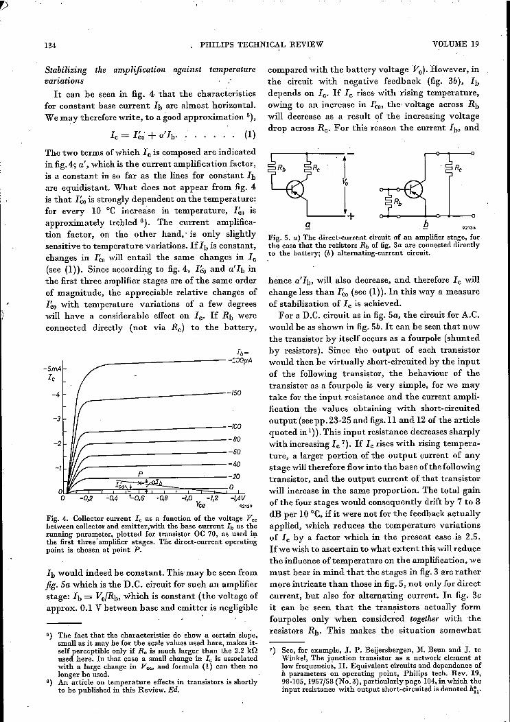
Stabilizing the amplification against tempertuurevariationsIt can be seen in fig. 4 that the characteristics
for constant base current h are almost horizontal.We m~y therefore write, to a good approximation 5),
Ic = I~ó + a'h. : . . . . . (1)
The two terms ofwhich Ic is composed are indicatedin fig. 4; a',which is the current amplification factor,is .a constant in so far as the lines for constant Ibare equidistant. What does not appear from fig. 4is that I~o is strongly dependent on the temperature:for every 10 oe increase in temperature, I~o isapproximately trebled 6). The current amplifica-tion factor, on the other hand,' is only slightlysensitive to temperature variations. IfIb is constant,changes in I~o will entail the same changes in Ic(see (1)). Since according to fig. 4., I~o and a'h inthe first three amplifier stages are of the same orderof magnitude, the appreciable relative changes ofI~o with temperature variations of a few degreeswill have a considerable effect on Ic. If Rb wereconnected directly (not via Rc) to the battery,
-SrnAi,
Ib=__--------------------~-:OOpA
~3
_-----------150-4
_------------100
__-------------80
__------------ro------------------~----~~~~----~---~0~~~~~~~~~~~~0~o -0,2 -0,4 -0,6 -0,8 -I,D -1,2 -I,4V
I{;e .213.
-2
-I
Fig. 4. Collector current le as a function of the voltage Veebetween collector and emitter,with the base current. h as therunning parameter, plotted for transistor OC 70, as used inthe first three' amplifier stages. Tlie direct-current operatingpoint is chosen at point P.
hwould indeed be constant. This-may be seen fromJig. Sa which is the D.e. circuit for such an amplifierstage: h= Vu/Rb, which is constant (the voltage ofapprox. 0.1 V between base and emitter is negligible
5) The fact that the characteristics do show a certain slope,small as it may be for the scale values used here, makes it-self perceptible only if Rc is much larger than the 2.2 kilused here. In that case a small change in le is associatedwith a large change in Vee, and formula (1) can then nolonger be used.
6) An article on temperature effects in transistors is shortlyto be published in this Review. Ed.
comparedwith the battery voltage Vu), However, inthe circuit with negative feedback (fig. 3b), hdepends on Ic. If Ic rises with rising temperature,owing to an increase in I~o, the voltage across Rbwill decrease as a result of the increasing voltagedrop across Rc. For this reason the current h, and
92136
Fig. 5. a) The direct-current circuit of an amplifier stage, forthe case that the resistors Rb of fig. 3a are connecteddirectlyto the battery; (b) alternating-current circuit.
hence a'h, will also decrease, and therefore Ic willchange less than I~u (see (1)). In this way a measureof stabilization of Ic is achieved.
For a D.e. circuit as in fig. Sa, the circuit for A.C.would be as shown in fig. Sb. It can be seen that nowthe transistor by itself occurs as a fourpole (shuntedby resistors). Since the output of each transistorwould then be virtually short-circuited by the inputof the following transistor, the behaviour of thetransistor as a fourpole is very simple, for we maytake for the input resistance and the current ampli-fication the values obtaining with short-circuitedoutput (seepp. 23-25 and figs.ll and 12 of the articlequoted in 1)).This input resistance decreases sharplywith increasing Ic 7). If L; rises with rising tempera-ture, a larger portion of the output current of anystage will therefore flow into the base of the followingtransistor, and the output current of that transistorwill increase in the same proportion. The total gainof the four stages would consequently drift by 7 to 8dB per 10 oe, if it were not for the feedback actuallyapplied, which reduces the temperature variationsof Ic by a factor which in the present case is 2.5.Ifwe wish to ascertain to what extent this will reducethe influence of temperature on the amplification, wemust bear in mind that the stages in fig. 3 are rathermore intricate than those in fig. 5, not only for directcurrent, but also for alternaring current. In fig. 3cit can be seen that the transistors actually formfourpoles only when considered together with theresistors Rb, This makes the situation somewhat
7) See, for example, J. P. Beijersbergen, M. Beun and J. teWinkel, The junction transistor as a network element atlow frequencies, n. Equivalent circuits and dependence ofh parameters on operating point, Philips tech. Rev. 19,98-105, 1957/58 (No. 3), particularly page 104, in which theinput resistance with output short-circuited is denoted h~l'
]957/58, No. 4 TRANSISTOR HEARING' AID 135
complicated. It will be enough here to report that thetotal gain of the hearing aid under discussion in-creases by only 2 to 3 dB per 10oe rise in temperature.Although the signal negative feedback reduces
amplification per stage, it makes the amplificationless dependent upon the properties of the individualtransistors. Since individual transistors of the sametype show a considerable spread in their properties.such stabilization is very welcome: the transistors inthe first three stages can now be replaced withoutany re-adjustments being necessary.Another adverse influence on the amplification is
the fact that the coupling' resistors Rc constituteparasitic loads on the transistors. The advantages ofsimple circuitry without transformers, and withstabilization against temperature variations, entailquite a considerable sacrifice of gain in the pre-amplifier. The theoretical maximum power gain ofan oe 70 transistor - i.e. the power gain with idealmatching at the input and the output - is about36 dB at the operating point considered. In theactual circuit, however, the first two amplifier stagesproduce only 19 dB each and the third 20 dB. Thefinal stage produces 22 dB, making an overall(electrical) gain of about 80 dB.
The output stage
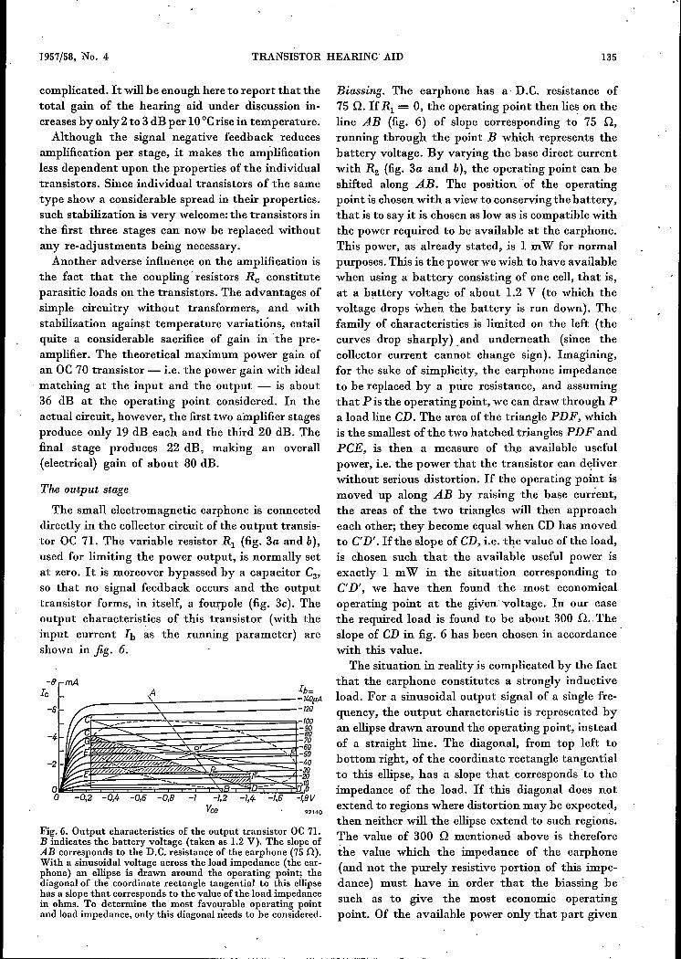
The small electromagnetic earphone is connecteddirectly in the collector circuit of the output transis-tor oe 71. The variable resistor RI (fig. 3a and b),used for limiting the power output, is normally setat zero. It is moreover bypassed by a capacitor C3,
so that no signal feedback occurs and the outputtransistor forms, in itself, a fourpole (fig. 3e). Theoutput characteristics of this transistor (with theinput current h as the running parameter) areshown in fig. 6.
mA
-I -/,2Vee
Fig. 6. Output characteristics of the output transistor oe 71.B indicates the battery voltage (taken as 1.2 V). The slope ofAB corresponds to the D.e. resistance of the earphone (75 Q).With a sinusoidal voltage across the load impedance (the ear-phone) an ellipse is drawn around the operating point; thediagonal of the coordinate rectangle tangential to this ellipsehas a slope that corresponds to the value of the load impedancein ohms. To determine the most favourable operating pointand load impedance, only this diagonal needs to be considered.
92140
Biassing. The earphone has a- D.e. resistance of75 n. IfRI = 0, the operating point then Iies on theline AB (fig. 6) of slope corresponding to 75 n,running through the point B which .represents thebattery voltage. By varying the base direct currentwith R2 (fig. 3a and b), the operating point can beshifted along AB. The position of the operatingpoint is chosen with a view to conserving the battery,that is to say it is chosen as low as is compatible withthe power required to be available at the earphone.This power, as already stated, is 1 mW for normalpurposes. This is the power we wish to have availablewhen using a battery consisting of one cell, that is,at a battery voltage of about 1.2 V (to which thevoltage drops when the battery is run down). Thefamily of characteristics is limited on the left (thecurves drop sharply). and underneath (since thecollector current cannot change sign). Imagining,for the sake of simplicity, the earphone impedanceto be replaced by a pure resistance, and assumingthat P is the operating point, we can draw through Pa load line CD. The area of the triangle PDF, whichis the smallest of the two hatched triangles PDF andPCE, is then a measure of the available usefulpower, i.e. the power that the transistor can deliverwithout serious distortion. If the operating point ismoved up along AB by raising the base current,the areas of the two triangles will then approacheach other; they become equal when CD has movedto C'D'. If the slope of CD, i.e. the value of the load,is chosen such that the available useful power isexactly 1 mW in the situation corresponding toC'D', we have then found the most economicaloperating point at the given voltage. In our casethe required load is found to be about 300 n..Theslope of CD in fig. 6 has been chosen in accordancewith this value.
The situation in reality is complicated by the factthat the earphone constitutes a strongly inductiveload. For a sinusoidal output signalof a single fre-quency, the output characteristic is represented byan ellipse drawn around the operating point, insteadof a straight line. The diagonal, from top left tobottom right, of the coordinate rectangle tangentialto this ellipse, has a slope that corresponds to theimpedance of the load. If this diagonal does notextend to regions where distortion may be expected,then neither will the ellipse extend to such regions.The value of 300 n mentioned above is thereforethe value which the impedance of the earphone(and not the purely resistive portion of this impe-dance) must have in order that the biassing be .such as to give the most economic operatingpoint. Of the available power only that part given

136 PHILIPS TECHNICAL REVIEW VOLUME 19
by the area of triangle P'E'G is dissipated 'in theearphone.
Since the impedance of the earphone depends onthe frequency, it can only he exactly 300 Q for· onefrequency. Earphones are used which have thisimpedance at a frequency of 1000 cis.A second complication is that no definitive conclusion can
be drawn from fig. 6 regarding the distortion to he expected.It is not at all evident, for instance, that serious distortionoccurs if the transistor is driven to very small values of le' Thisdistortion is due to the fact, already mentioned; that the inputresistance of the. transistor increases sharply at small values ofle. Nevertheless, the method indicated above of determiningthe most economical operating point and the most favourableload impedance from fig. 6 does lead to results of practicalvalue..
Since the current amplificationfactor ofthe OC 71transistor may vary between 30 and 75 withindividual transistors of the same type, the basecurrent at which the most fav'ourable operating pointis obtained depends upon the transistor employed.It must therefore be possible to adjust the basecurrent during assembly and subsequently if re:placement of the output transistor should benecessary; this is the reason for making the resistorR2 variable.
Limiting. The operating point discussed above auto-matically provides that, with increasing input signal,the power increases only very little from the momentthat serious distortion sets in. This is due to the factthat the limiting ofthe output signal and the seriousdistortion associated with it both occur equallyonboth sides of the operating point (symmetricallimiting). In this way the output power is preventedfrom exceeding a certain upper limit, thereby pro-viding an effective safeguard against "acousticaltrauma".
The level at which the limiting becomes operativecan be regulated with resistor Rl (fig. 3b). The higherthis resistance, the lower the collector voltage. Thisvoltage is also across the base resistor R2 (the slightpotential difference between base and emitter isnegligible) and thus the base current falls pro-portionately when Rl is increased. In its turn, thecollector current Ic decreases proportionately withthe base current, at least as long as Ic> I~o (see(1». The operating point, is thus shifted along theline OP' (fig. 6) towards the origin; the symmetricalcut-off is thereby maintained.Since the amplification of the output stage is not
stabilized by negative feedback, the considerahlespread in the cun:ent amplification factor of indivi-dual output transistors would normally appear in
full in the total gain. To prevent this happening, avariable resistor R4 is introduced between the firstand second stages (fig. 3a and c) with which thetotal gain can be adjusted during assembly or afterthe replacement of the output transistor. This alsocompcnsates for the residual spread in the character-istics of the earlier stages, still remaining in spite ofnegative feedback.As regards direct current, too, there is no feedback
in the output transistor when Rl is set at zero, andtherefore no stabilization of the operating pointagainst teinperature variations. This is not necessary,however, since the collector bias current le of theoutput transistor is adjusted to a much higher valuethan that of the transistors in the first three stages.The contrihution of I~o to Ic is therefore relativelymuch smaller (see (1».If the battery voltage is doubled or trebled by
using a battery.consisring of two or three cells, theoperating point moves along OP' away from the'origin. The maximum amplitudes of current andvoltage are also doubled or trebled and the availableuseful power is increased by a factor of 4 or 9, as thecase may be. Thus, 'with a battery of three cells theavailable power is brought up to the 10 mW that 'isnecessary for some cases of severe deafness and whenbone conduction is employed. Raising the batteryvoltage causes an increase not only in the biassingcurrent of the output transistor but also in that ofthe transistors in the first three stages, Since higheroperating currents entaillower input resistance, theloss in the resistors Rc (fig. 3c) is lower. This causesthe total gain acoustic to increase from 55 dB forone battery cell to 63 dB and 67 dB for two andthree cells respectively.
With all three battery voltages the resistor Rlallows the ear specialist to lower the maximum out-put power (the ceiling) èontinuously by an amountfrom 0 to 20 dB. It can be seen in fig. 3b that thelimiting of the output is associated with a reductionin battery current, as one would wish.
Microphone, earphone and response curves
The input resistance of the first amplifier stage isrelatively low, being somewhere between 1000Q and1800 Q, and thus readily permits the direct connec-tion of a moving-iron microphone. Crystal micro-phones, as normally used in valve hearing aids, callfor load impedances of the order of 0.1 to 0.5 MQ.This would necessitate the use of a matchingtransformer, and even then less power would bedelivered, with more noise. The moving-iron micro-phone used in the KL 5500 hearing aid has an internalresistance of 1000Q and is particularly suitable for

1957/58, No. 4 TRANSISTOR HEARING AID 137
use with transistor hearing aids. Its smooth fre-quency characteristic facilitates the attainment ofthe desired overall response curve. The microphonefunctions as follows 8). The vibrations of an alumi-nium diaphragm are transferred to an armaturecomposed of a materialof high permeability, Thisarmature constitutes the "galvanometer" diagonalof a magnetic "Wheatstone bridge". The resistancearms are formed by air-gaps in the magnetic system,and the requisite magnetic flux is supplied by a smallpermanent magnet forming the other diagonal of thebridge. The magnetic fl~x through the armature isdependent in direction and. magnitude 'upon itsdeviation from its equilibrium position. A coil fittedaround the armature converts the flux variations intoan alternating voltage. The system is extremely sen-sitive: at 1 kcls the sensitivity is about 0.3 mVIfJ-barwhen the microphone is terminated by 1000 Q.By means of suitably dimensioned resonant aircavities the frequency characteristic can be madefairly flat between 400 and 3000 cis, which is theimportant range for speech (fig. 7). The consequenceof these measures is that the characteristic falls moresharply outside this range, which has the advantage,
- t-......- ..... \
\I- I- ,
V// 1\
1/ \\
/ \
200 300 500 1000 . 2CXXJ 3000 5(XX)cfs-f' 02142
Fig. 7. Frequency characteristic of the microphone. The quanti-ty actually plotted is the voltage across a resistor of 1000 nterminating the microphone, the latter being in a sound field ofconstant pressure.
where the lower frequencies are concerned, of veryefficiently suppressing intermodulation phenomena;which may occur in the presence of "boom", in.motor vehicles, for example.
The microphone casing is surrounded by tworings of a metal with a high initial permeability, thepurpose of which is to shield the microphone against
8) For a detài1ed description see: B. B. Bauer, A miniaturemicrophone for transistorized amplifiers, J: Acoust.· Soc.Amer. 25, 867-869, 1953.
stray magnetic fields (attenuation by about 16 dB)and to help create a quiet background.As regards the earphone, the patient has a choice
of three types. The type Ph 1 earphone has an almostflat frequency characteristic (fig. 8). Unavoidable
~V ., ,,..- . 1\ \/ 1\ ,
1= '= Phi ....- f/ \. .\Ph, jt}\
._ f-. --Iph2 - -~I-" _1_u. ~
_l
f
200 XXJ 500 lOOO 2000 3000 9XJJc/s-f 02143
Fig. 8. Frequency characteristics of the three earphones (Ph 0,Ph 1, Ph 2) from which patients may choose.As a function ofthe frequency f of the constant current through the earphone,the sound pressure is plotted as measured in an artificial ear of2 cmêvolume in which the earphone was fixed.
resonances have been attenuated as much as possibleby the introduetion of damping. Fig. 8 also showsthe characteristics of the two other earphones, typesPh 0 and Ph 2. In these types the resonances areattenuated to a lesser extent.With. the sum of the frequency characteristics of
microphone, amplifier and earphone, an overallresponse curve (fidelity characteristic) is obtained asshown in fig. 9, using an earphone of the type Ph 1.By switching Cl or C2 (fig. 3), a portion ofthe low or
:2':~ "., I.....
~ L. \~,,- , , -,r ,
\/ \.
/ .' ,/ _L ~
L _L . ,
.{
:200 300 500 1000 JOOO 3000 5OOOc15_f
85893
Fig. 9. Overall response curves (fidelity characteristics) of the.complete hearing aid KL 5500 with earphone Ph 1, for thethree positions of the control switch. The quantity plotted isthe sound pressure measured in an artificial ear' of 2 cm3
volume in which the earphone was fixed, the microphone beingin a field of constant pressure .. Full curve: SI closed, S2 open (see fig. 3c); dashed curve:St and $2 both closed; dot-dashed curve: SI open, S2 open.
138 PHILlPS TECHNICAL REVIEW VOLUME 19
high frequency range, respectively, can be cut off,producing the three curves illustrated. These curvescan also be changed by the choice of earphone, sothat.many combinations are possible.
Case noise
. The extremely low battery costs make it possibleto keep this hearing aid in continuous use, This beingso, it is' more important than ever that the usershould be able to hear with the least ,possible effort.Various factors are involved here, an important onebeing, as we have seen, that the tone quality per-ceived by the deaf person should be as agreeable aspossible, heard against a quiet background. The mosttroublesome kind of background interference heardby users of hearing aids is case noise. This is causedby friction between clothing and the case of theinstrument, or by frict:ion between a piece of clothingstretched over the case and an adjacent fabricrubbing over it. Modern hearing aids are so smoothlyfinished, and there is so little movement of clothingwith respect to the case, that the first source of casenoise may, for all practical purposes, be neglected.The movement between adjacent fabrics bearing onthe case, however, is many times greater in amplitudeand is always present. It has the nature of "whitenoise"; that is to say, all frequencies in the bandpassed by the hearing aid are represented in almostthe same intensity. Sufferers from certain types ofdeafness may find this extremely troublesome, andit is therefore very important to suppress this kindof interference: 'as' effectively as possible.The vibrations produced by case noise can reach
the microphone in three ways.a.) The friction may set the case and the chassis ofthe instrument in vibration; the vibration is trans-mitted to the microphone via the microphonemounting. This transmission is almost entirelydetermined by the natural resonance of the systemconsisting of the microphone (mass) and its elasticmounting (stiffness). The natural frequency caneasily be kept below 100 cis, in which case theamplitude of vibrations within the speech rangeremains negligible.b) The vibrations of the case can be transmitted toair cavities inside the hearing aid. These cavitiesoften resonate and thereby pass certain fre-quency ranges with extra intensity. The vibrations
. may possibly reach the microphone via thesecavities.c) The vibrations of the clothing material reach themicrophone diaphragm via the air in the normalway.
. An apparatus has been developed by Philips formaking comparative measurements of the sensitivi ..ty of different hearing aids to case noise. The resultsof such measurements make it possible to assessobjectively the measures taken to suppress inter-ference due to case noise.The apparatus contains an endless cotton belt
driven by a small motor. The hearing aid to betested is pressed against the moving belt, either withor without an intermediate piece of clothing fabricstretched over the case. The case noises thus pro-duced are reproducible, Iand in a certain sense"standardized". The earphone of the hearing aidis fixed in an "artificial ear", and the voltage pro-duced in the microphone of this device is fed to avoltmeter via a band-pass filter (bandwidth onethird). The case noise is subsequently stopped and astandardized "acoustic" noise substituted, i.e. a noisewhose vibrations reach the instrument's micro-phone only by the normal acoustical means, that isvia the air and not by the means mentioned undera) and b) above. This acoustic noise is producedby a loudspeaker set up nearby the hearing aid andfed by a noise generator. The volume of the acousticnoise is adjusted such that the deflection of thevoltmeter is the same as when the case noise wasoperative. A measurement is then made of the soundpressure of the acoustic noise field at the positionof the hearing aid; this is done with the aid of amicrophone connected via the same filter to a volt-meter which is calibrated in decibels above athreshold value of 10-4 dyne/cm2• In this way thesound pressure is. ascertained of the acoustic noisewhich, within a frequency band of one third, pro-duces just as much interference as the standard-ized case noise. By repeating the measurement withdifferent band-pass filters of one third, the entire
/' r'71/
LI 1-\. 1.1 7"- V I
i'-.. r- ....r-, r- 17
......t-.., 17f'.: I--
{
200 m 500 1CXXJ 2CXXJ XXX)_f
!XXX)cjs921 ....
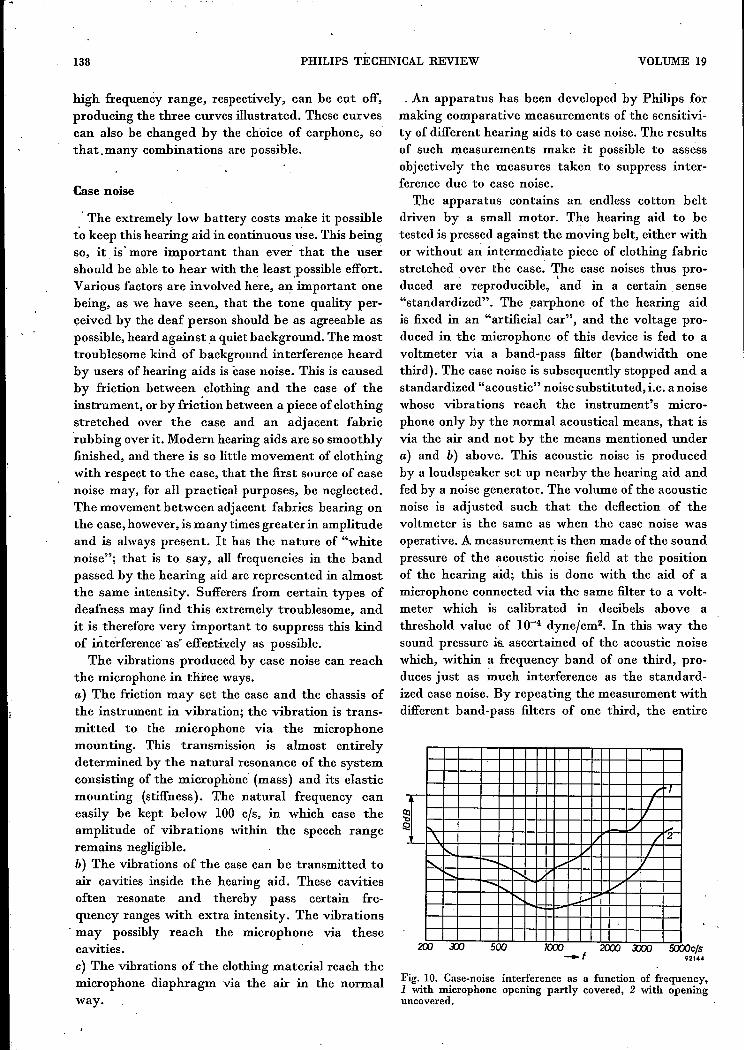
Fig. 10. Case-noise interference as a function of frequency,1 with microphone opening partly covered, 2 with openinguncovered.
1957/58, No. 4 TRANSISTOR HEARING AID 139
audio frequency-range can be covered. The advan-tage of this method is that the results depend onlyupon the extent to which the case-noise vib~ationsreach the microphone of the hearing aid, and notupon the amplification or the response curve of theinstrument.
The method can also be used to investigate theeffect of the conditions under which the case noiseis generated. As an example,jig. 10 shows the effectofpartly covering the microphone opening by vibrat-ing fabric. With a given amplitude of vibration, thevariations in air pressure in the small cavity in frontof the microphone diaphragm are larger the morecompletely the opening is covered. It is seen fromfig. 10 that when the opening is partly covered theinterference is greater at all frequencies than whenthe opening is uncovered; in the range of about 1000to 3000 cfs the difference is as much as 10 dB. It isimportant, therefore, when wearing a hearing aid,to keep the microphone opening entirely free.
The results of case-noise measurements have led-tothe adoption of various measures in the mechanicalconstruction of the type KL 5500 hearing aid - and ,in other types too - to suppress this-rrrterferenee.It has been found that apparently minor modifica-tions often have a substantial effect.
'Summary. The use of transistors in the KL 5500 hearing aidhas made it possible tb reduce battery costs drastically and atthe same Fime to increase the available output power andamplification. As a resnlt, the apparatus can serve a widecircle of deaf persons. After a discussion of the various require-ments to be satisfied by a hearing aid, a description is given ofthe amplifier, in which four transistors are used. The effects oftemperature variations and of the spread in the properties ofindividual transistors are largely eliminated by means ofnegative feedback. The highly sensitive moving-iron micro-phone is directly coupled to the input stage, without the inter-mediary of an input transformer. A transformer is also super-fluous for the earphone, since with transistors the maximumavailable power is obtained with a load having an impedance ofa fewhundred ohms, whichis the normal impedance for electro-magnetic earphones. The variable limiter prevents the maxi-.mum output power from exceeding the threshold of pain. Thearticle concludes with some details of investigations into theinterference caused by case noise.


![SHORTREPORT Anti-Toxoplasma gondiiantibodies ... · anemia,paincrises,infections,ulcersandrecurrentvaso-occlusiveevents[ 1, 2]. ... 31. GarciaMN,Woc‑ ColburnL,RossmannSN,TownsendRL,StramerSL,](https://static.fdocuments.in/doc/165x107/5b6b0bae7f8b9aad038ce2a4/shortreport-anti-toxoplasma-gondiiantibodies-anemiapaincrisesinfectionsulcersandrecurrentvaso-occlusiveevents.jpg)