A Transfer Function Approach to Harmonic Filter Design
15
I I I I I I I I I I I I I I I I I I I I I I I I I I I I I I I I I I I I I I I I I I I I I I I I I I I I I I I I I I I I I I I I I I I I I I I I I I I I I I I I I I his article details a new transfer function approach in passive harmonic filter design for industrial and commercial power sys- tem applications Filter placement along with six common filter configurations are presented. Har- monic impedance, voltage division and current di- vision transfer functions are derived and used in a practical filter design procedure that incorporates IEEE-5 19 distortion limits directly into the design and component specification process. A simple four-step filter design procedure is outlined and used in a variable speed motor drive pumping plant application Several factors need to be considered before a fil- ter design is undertaken. In all cases, there will be a number of reasons why filters are required. These may include utility-imposed distortion limits, telephone interference complaints for existing drive installations, parallel resonance and system problems, poor power quality resulting from one or more motor drives or rectifier loads sharing a common coupling, engineering specification re- quirements, or simply that the drive manufacturer is just a nice guy. (Although this last example is rare in industry ) Drive manufacturers notoriously do not want to deal with harmonic distortion un- less they are forced to by other political or economi- cal factors, since it increases the cost and complexity oftheir product and tends to make each installation specialized However, harmonic dis- tortion is quickly becoming a very hot topzc throughout the power industry-especially with the new version of IEEE-519 Since the drive manufactures tend to be slow to change their basic designs incorporating new technology such as high-quality rectification 111, and since active fil- ter systems still appear to be a few years away from Thzs artzcle uppeared zn zts orzgznal firm at the 1995 Petroleum C Chemzcal Industry ConJrence The authvr, an IEEE Member, zs aprznczpal with Peak Power Engz- neerzng, Golden, Colo. being readily available on the market, passive har- monic filter systems are being used extensively to interface both existing and new large motor drive converter systems Therefore, the need for an effec- tive filter design procedure is justified Currently, passive harmonic filter application is the method practiced most often and is readily available to power system engineers and designers for reducing harmonic voltage and current distor- tion through alternate circuit path operation Sev- eral IEEE transaction papers have been written and published that introduce the theory and imple- mentation of advanced techniques for controlling harmonic current flow such as magnetic flux com- pensation, harmonic current injection, dc ripple injection, series and shunt active filter systems, and pulse-width modulated static var harmonic com- pensators However, practical systems have not been extensively developed and are not yet avail- able on the market It may still be some time before these advanced techniques are fully developed and are readily available so as to successfully compere with passive harmonic filter systems, by the time they can compete, advanced rectifiericonverter de- signs that use active line current-shaping tech- niques will reduce the need for large-scale harmonic filtering systems in new installations, as- suming industry implements the technology Hence, the life expectancy and success of these ad- vanced harmonic control techniques may be lim- ited Until that time arrives, if it even does, passive harmonic filters can be designed and applied alone or in combination with transformer phase shifting and/or higher pulse number rectifier configura- tions to control waveform distortion on the power system This article deals exclusively with passive har- monic filter design Six common filter configura- tions are presented Possibly for the first time, a transfer function approach to filter design and sys- tem modeling performance is presented that can he setup to account for harmonic distortion control limits directly in the filter design process The I m IEEE Industry Applicufians Muguzine 1 Murch/April I997 I 1077-2618/971$10.000 1997 IEEE
description
Harmonic Filter design
Transcript of A Transfer Function Approach to Harmonic Filter Design
I I I I I I I I I I I I I I I I I I
I I I I I I I I I I I I I I I I I I I I I I I I I I I I I I I I I I I I I I I I I I I I I I I I I I I I I I I I I I I I I I I I
his article details a new transfer function approach in passive harmonic filter design for industrial and commercial power sys-
tem applications Filter placement along with six common filter configurations are presented. Har- monic impedance, voltage division and current di- vision transfer functions are derived and used in a practical filter design procedure that incorporates IEEE-5 19 distortion limits directly into the design and component specification process. A simple four-step filter design procedure is outlined and used in a variable speed motor drive pumping plant application
Several factors need to be considered before a fil- ter design is undertaken. In all cases, there will be a number of reasons why filters are required. These may include utility-imposed distortion limits, telephone interference complaints for existing drive installations, parallel resonance and system problems, poor power quality resulting from one or more motor drives or rectifier loads sharing a common coupling, engineering specification re- quirements, or simply that the drive manufacturer is just a nice guy. (Although this last example is rare in industry ) Drive manufacturers notoriously do not want to deal with harmonic distortion un- less they are forced to by other political or economi- cal factors, since it increases the cost and complexity oftheir product and tends to make each installation specialized However, harmonic dis- tortion is quickly becoming a very hot topzc throughout the power industry-especially with the new version of IEEE-519 Since the drive manufactures tend to be slow to change their basic designs incorporating new technology such as high-quality rectification 111, and since active fil- ter systems still appear to be a few years away from
Thzs artzcle uppeared zn zts orzgznal f irm at the 1995 Petroleum C Chemzcal Industry ConJrence The authvr, an IEEE Member, zs aprznczpal with Peak Power Engz- neerzng, Golden, Colo.
being readily available on the market, passive har- monic filter systems are being used extensively to interface both existing and new large motor drive converter systems Therefore, the need for an effec- tive filter design procedure is justified
Currently, passive harmonic filter application is the method practiced most often and is readily available to power system engineers and designers for reducing harmonic voltage and current distor- tion through alternate circuit path operation Sev- eral IEEE transaction papers have been written and published that introduce the theory and imple- mentation of advanced techniques for controlling harmonic current flow such as magnetic flux com- pensation, harmonic current injection, dc ripple injection, series and shunt active filter systems, and pulse-width modulated static var harmonic com- pensators However, practical systems have not been extensively developed and are not yet avail- able on the market It may still be some time before these advanced techniques are fully developed and are readily available so as to successfully compere with passive harmonic filter systems, by the time they can compete, advanced rectifiericonverter de- signs that use active line current-shaping tech- niques will reduce the need for large-scale harmonic filtering systems in new installations, as- suming industry implements the technology Hence, the life expectancy and success of these ad- vanced harmonic control techniques may be lim- ited Until that time arrives, if it even does, passive harmonic filters can be designed and applied alone or in combination with transformer phase shifting and/or higher pulse number rectifier configura- tions to control waveform distortion on the power system
This article deals exclusively with passive har- monic filter design Six common filter configura- tions are presented Possibly for the first time, a transfer function approach to filter design and sys- tem modeling performance is presented that can he setup to account for harmonic distortion control limits directly in the filter design process The
I m IEEE Industry Applicufians Muguzine 1 Murch/April I997
I
1077-2618/971$10.000 1997 IEEE
Harmonic
Locations
L- - - 'y-J
Finite Load
Power Transformation One or More
Non-Linear Harmonic Sources
Equivalent System
Impedance Infinite Source
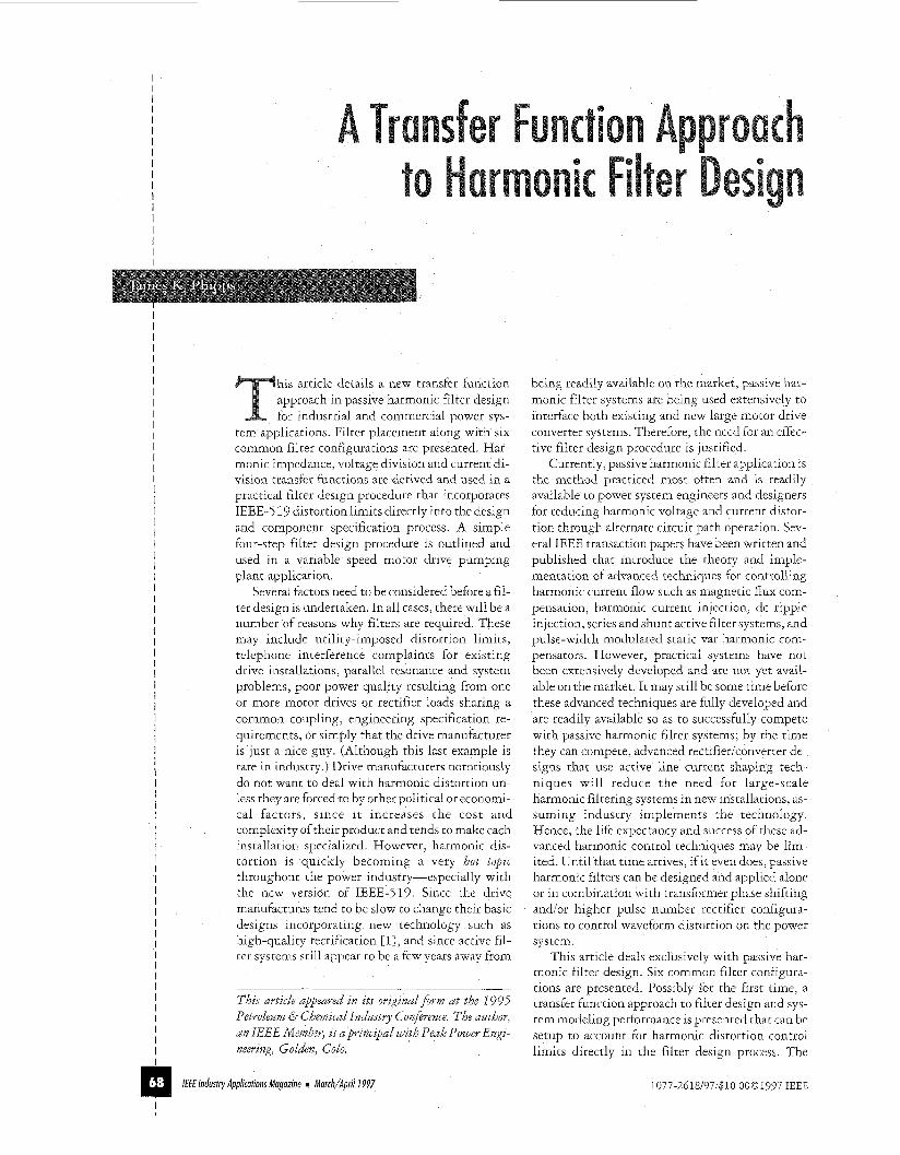
Fig. 1. Practical filter locations.
ANSUIEEE-5 19 harmonic distortion limits and guidelines are incorporated into a practical filter design procedure, and a simple example that ap- plies these steps is presented.
Filter Placement As shown in Fig. 1, there are two practical locations where passive harmonic filters may be effectively applied. Similar to power factor correction capaci- tor placement, the optimum location results in maximized harmonic reduction performance and minimized equipment costs and system losses. Many times, placing the filter system as near to the nonlinear load as possible (i.e., at the same voltage level, preferably at the motor drive terminals) re- sults in the greatest attenuation of harmonic dis- tortion for a given filter reactive power rating. There are both advantages and disadvantages for either filter location as well as several economic al- ternatives to consider. In any case, however, the analysis begins with the generalized frequency- dependent filter system impedance representation Zfi This impedance can take on several forms de- pending on the desired response, and it is the basic building block on which several useful filter sys- tem design transfer functions can be defined.
Fiher Transfer Functions [Z] There are a number of important transfer functions that can be derived for filter design and system modeling purposes. As in all three-phase power system analysis, one of the main design goals is to maintain balanced voltages and currents in the net- work and to maintain reliability and efficiency. With these in mind, the following transfer func- tions are based on single-phase equivalent circuits assuming that the system is designed and operated under balanced conditions. Although it is beyond the scope of this article to discuss unbalanced har- monic systems, ifthe system were to operate unbal- anced, symmetrical component harmonic models and transfer functions could, with moderate effort, be derived and used in addition to a complete three-phase computer simulated model to approxi- mate the unbalanced conditions and system re-
If(@
Zf(S) 1-I' VfW
-
Fig. 2. Filter impeddnce representation.
Fig. 3 . FilterlSystem impedance representation.
sponses. When filter systems are used in unbal- anced loading conditions, the basic single-phase design relations can still be used to calculate the initial component values. Those values can then be inserted into a full three-phase unbalanced model for further analysis and design refinement. Fortu- nately, the application of single-phase rectifier loads that cause unbalanced harmonic systems are of the low power type and, therefore, represent only a small fraction of harmonic producing loads in general. Therefore, the need for unbalanced har- monic analysis and filter operation is much less than it is for balanced operation.
Filter Impedance Transfer Function This transfer function is the basic building block on which the modeling begins. It is defined to be the complex impedance frequency response of the filter system expressed in the s-domain of the indi- vidual filter circuit elements. As shown in Fig. 2, if
I I I I I I I I I I I I I I I I I I I I I I I I I I I I I I I I I I I I I I I I I I I I I I I I I I I I I I I I I I I I I I I I I I I I I I I I I I I I I I I I I I I I I I I I I I I I
lfff hdusfiy Applicafionr Magozhe m Marrh/Aprill997
I I I I I I I I I I I I I I I I I I I I
a general filter branch is defined at its terminals, (1) can be defined as follows:
where
function H f ( s i = Filter impedance s-domain transfer
Zf(s) = Filter s-domain complex impedance Vf(s) = Single-phase equivalent filter s-domain
I voltage I I
I f ( s ) = Filter branch s-domain current
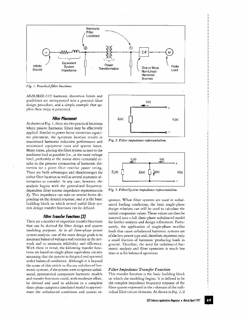
Fig. 4. First-order high-pass. I
-20dBlD
+20dB/D
Fig. j., First-order damped high-pass.
As mentioned above, Zf(s) is considered to be a single phase equivalent impedance when used to model a three-phase system. If the actual filter is configured in a delta connection, care must be taken not to confuse line-to-line and line-to neutral impedances when using (1) For balanced three-phase systems, (2) is used as the wye-delta transform.
1 Z" =-z 3 A
where Z y = Line-to-neutral, Wye, impedance 20 = Line-to-line, Delta, impedance
H f ( s ) can be used to design and tune the filter as a separate system before it is modeled in the power system network Depending on the type and com- plexity of the filter configuration, Zf(si can be fac- tored into a combination of denominators (poles) and numerators (zeros) substituting
to derive the parcicular tuning and damping rela- tions between component variables.
FilterlSystem Impedance Transfer Function After the filter system is configured and Zf(J-) is known, this impedance can be connected to the power system network to derive the filterlsystem impedance transfer function Hfi(s) where Zs(s) is represented as the system Thevenin equivalent sys- tem network impedance.
If other energy storage elements such as capaci- tances and/or inductances exist in the power sys- tem network, they will affect the overall performance of the filter system when it is in- stalled HfiS(s) is a powerful tool that can be used to gain insight into the combined frequency response of the filter connected to the system.
Current Divider Transfer Function There are two types of the current divider transfer functions that can be derived for the filter system connected to the power system network. Referring to Fig. 3, Hcds(s) is the ratio ofsystem current to in- jected current and H.df (s) is the ratio of filter cur- rent to injected current.
I
IF€€ Industry Applications Magazine = March/Aprill997
Transfer functions (9) and (10) are very impor- tant because they serve two roles When the filter system is being designed, the impedances of the transfer functions can be used to assess the overall system performance After the filter system is in- stalled and operational, the harmonic current flows can be measured and the appropriate current di- vider ratios can be computed and plotted on the same graph for a filter performance comparison of designed vs measured response Equation ( 5 ) is useful for designing and determining harmonic current distortion limit compliance with IEEE- 5 19 limits [31
As discussed later, the IEEE-5 19 current dis- tortion limits can be used in conjunction with the expected harmonic current injection from the converter rectifier to compute the minimum current divider ratios required to meet the im- posed limits These ratios can then be used to de- fine the minimum filter attenuations for which Hcds(l) is based.
Voltage Divider Transfer Functions A similar class of transfer functions can be devel- oped for systems where harmonic voltage sensitive loads exist and the designer is mainly interested in developing filter systems to provide frequency de- tuning or voltage distortion control. This class of transfer functions is based on a voltage division be- tween an equivalent harmonic voltage source and harmonic sensitive loads. The nomenclature for this class of transfer functions is typically expressed as Hods (s), where vds refers to the harmonic voltage division with respect to the source. A typical use for this type of system representation is in solving
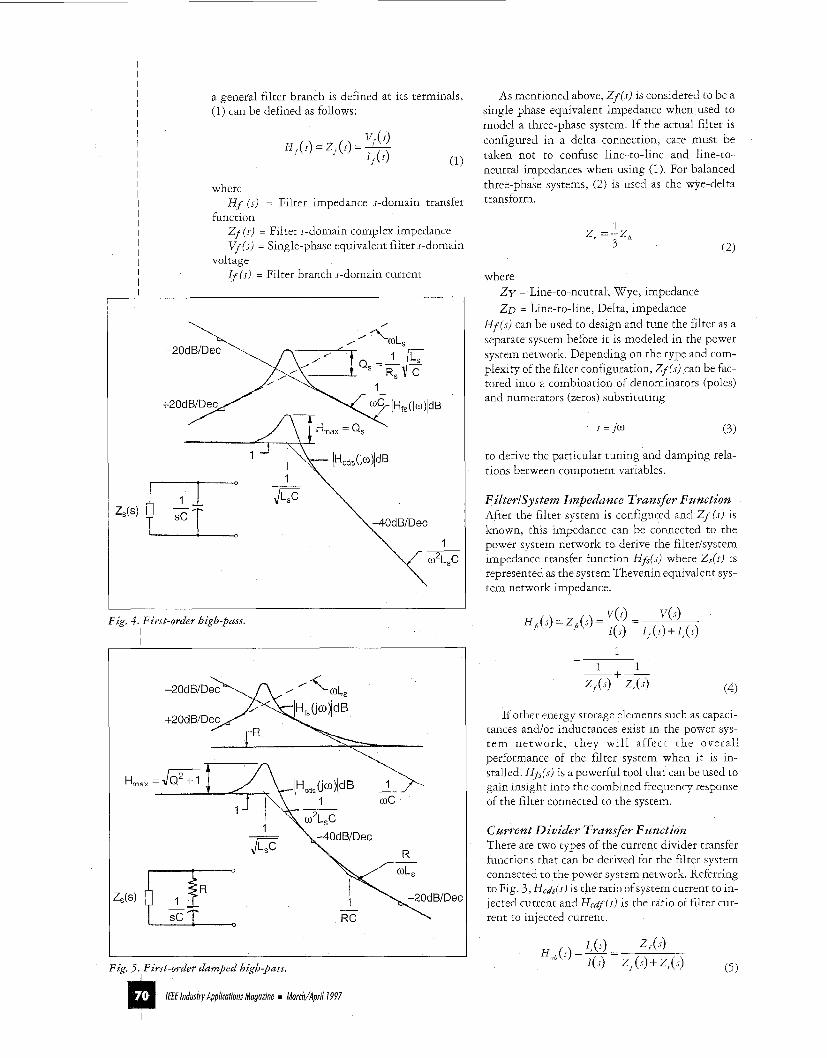
Fig. 6. First-order damped high-pass filter behind a series reactance.
+
Fig. 7. Second-order series resonant filter.
I I
Fig. 8. Second-order filter impedance transfer function.
shunt power factor capacitor parallel or series reso- nant amplification effects of voltage distortion at locations where harmonic sensitive loads exist or high power quality is desired.
First-Order High-P ass Filter A first-order filter consists of a capacitor bank con- nected directly to the power system bus and it is typically intended to filter high frequency har- monics from the system as shown in Fig. 4, with the system impedance assumed to be a simple in- ductance, Z,(s) = sL,. The “order” of the filter, in
I I I I I I I I I I I I I I I I I I I I I I I I I I I I I I I I I I I I I I I I I I I I I I I I I I I I I I I I I I I I
IEF Industry Applications Magazine m March/April I997
I I I I I I I I I I I I I I I I I I I I I I I I I I I
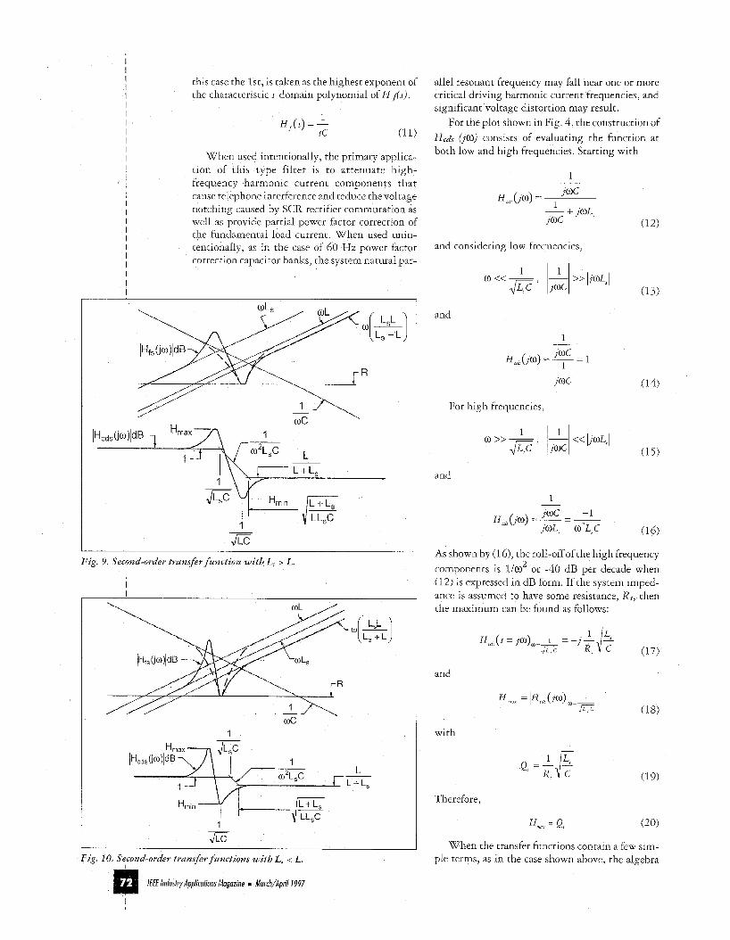
this case the lst, is takenas the highest exponent of the characteristic s-domain polynomial of H f i s ) .
When used intentionally, the primary applica- tion of this type filter is to attenuate high- frequency harmonic current components that cause telephone interference and reduce the voltage notching caused by SCR rectifier commutation as well as provide partial power factor correction of the fundamental load current When used unin- tentionally, as in the case of 60 Hz power factor correction capacitor banks, the system natural par-
I \ \ I L + L 1 \ ';i
Fig. 9. Second-order t rans fer f u n c t i o n with L, > L.
W C 1
L .- L+L,
1 --b- 1 __
E Fig. 10. Secondorder t rans fer f u n c t i o n s with L, i L.
allel resonant frequency may fall near one or more critical driving harmonic current frequencies, and significant voltage distortion may result.
For the plot shown in Fig. 4, the construction of Hcds (10) consists of evaluating the function at both low and high frequencies Starting with
1
(12)
and considering low frequencies,
and
For high frequencies,
and
1
As shown by (1 6), the roll-off of the high frequency components is 1/0 or -40 dB per decade when (12) is expressed in dB form. If the system imped- ance is assumed to have some resistance, Rs, then the maximum can be found as follows:
2
-
and
with
Therefore,
Hrn, = Q, (20)
When the transfer functions contain a few sim- ple terms, as in the case shown above, the algebra
/€FE Industry Applications Magazine I Murch/Aprill997
I
required to derive analytical closed-form expres- sions for the asymptotes and local maxima and minima is fairly straightforward.
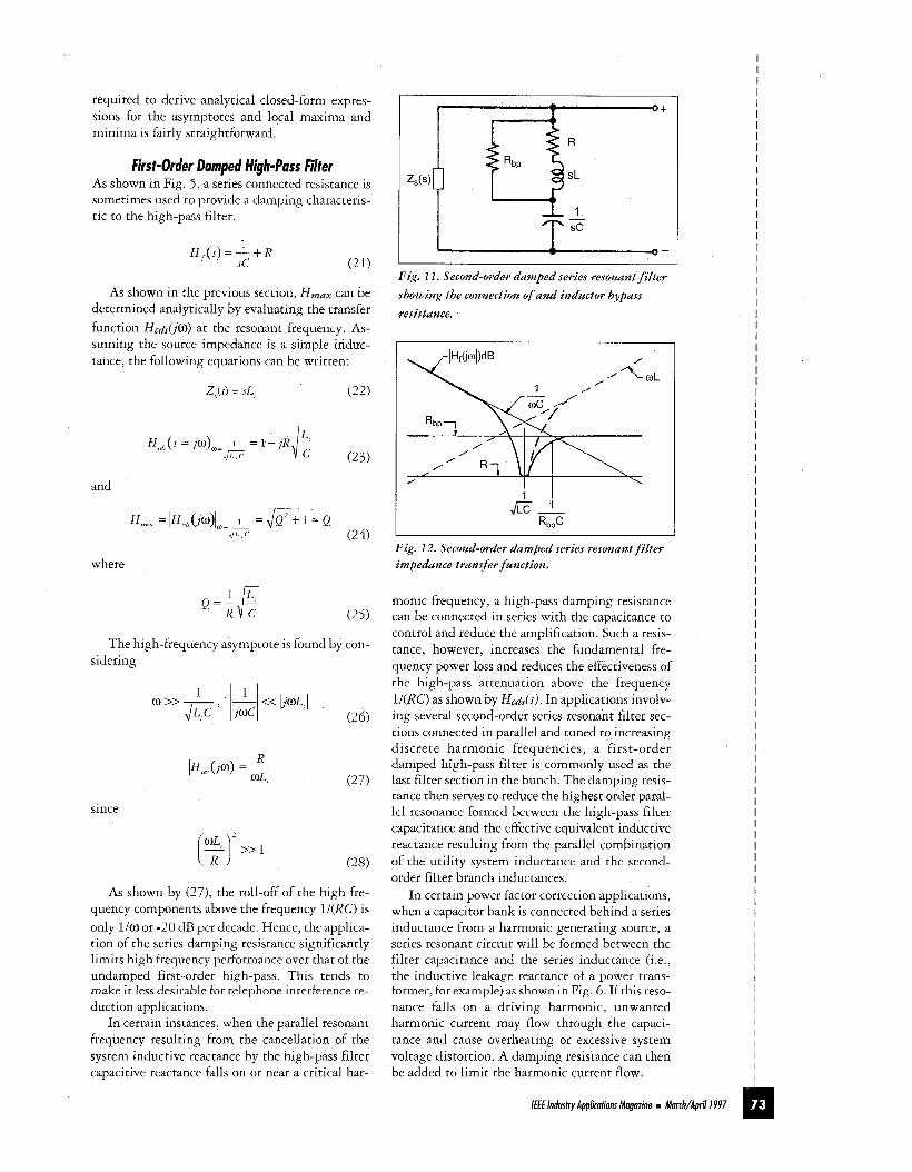
First-Order Damped High-Pass Filter As shown in Fig. 5 , a series connected resistance is sometimes used to provide a damping characteris- tic to the high-pass filter.
H f (s) = + R sc
As shown in the previous section, H,,, can be determined analytically by evaluating the transfer function Hc&O) at the resonant frequency. As- suming the source impedance is a simple induc- tance, the following equations can be written:
Z$) = SL, (22)
and
where
Q = - L
R C ' P The high-frequency asymptote is found by con-
sidering
since
[%)2 >> 1
As shown by (27), the roll-off of the high fre- quency components above the frequency 1/(RC) is only liO or -20 dB per decade Hence, the applica- tion of the series damping resistance significantly limits high frequency performance over that of the undamped first-order high-pass This tends to make it less desirable for telephone interference re- duction applications
In certain instances, when the parallel resonant frequency resulting from the cancellation of the system inductive reactance by the high-pass filter capacitive reactance falls on or near a critical har-
r O +
5- Fig. 11. Second-order damped series resonant filter showing the connection of and inductor bypass resistance.
1 1 GL
RbpC I I
Fig. 12. Second-order damped series resonant filter impeddnce transfer function.
monic frequency, a high-pass damping resistance can be connected in series with the capacitance to control and reduce the amplification Such a resis- tance, however, increases the fundamental fre- quency power loss and reduces the effectiveness of the high-pass attenuation above the frequency lI(RC) as shown by Hcds(s) In applications involv- ing several second-order series resonant filter sec- tions connected in parallel and tuned to increasing discrete harmonic frequencies, a first-order damped high-pass filter is commonly used as the last filter section in the bunch The damping resis- tance then serves to reduce the highest order paral- lel resonance formed between the high-pass filter capacitance and the effective equivalent inductive reactance resulting from the parallel combination of the utility system inductance and the second- order filter branch inductances
In certain power factor correction applications, when a capacitor bank is connected behind a series inductance from a harmonic generating source, a series resonant circuit will be formed between the filter capacitance and the series inductance (I e , the inductive leakage reactance of a power trans- former, for example) as shown in Fig 6 If this reso- nance falls on a driving harmonic, unwanted harmonic current may flow through the capaci- tance and cause overheating or excessive system voltage distortion A damping resistance can then be added to limit the harmonic current flow.
I I I I I I I I I I I I I I I I I I I I I I I I I I I I I I I I I I I I I I I I I I I
I
I I I I I I I I I I I I I I I m Iff€ Industry Applications Magazine m March/Aprill997
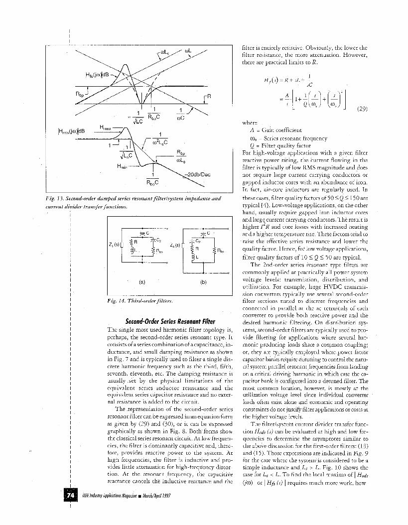
Fig. 13 . Second-order damped series resonant filterlsystem impedance and current divider transfer functions.
I I I I I I I I I I I I I I I I I I I I I I I I I
Fig. 14. Third-order filters.
r Series Resonant Filter The single most used harmonic filter topology is, perhaps, the second-order series resonant type. It consists of a series combination of a capacitance, in- ductance, and small damping resistance as shown in Fig. 7 and is typically used to filter a single dis- crete harmonic frequency such as the third, fifth, seventh, eleventh, etc. The damping resistance is usually set by the physical limitations of the equivalent series inductor resistance and the equivalent series capacitor resistance and no exter- nal resistance is added to the circuit
The representation of the second-order series resonant filter can be expressed in an equation form as given by (29) and (30), or it can be expressed graphically as shown in Fig. 8. Both forms show the classical series resonant circuit At low frequen- cies, the filter is dominantly capacitive and, there- fore, provides reactive power to the system. At high frequencies, the filter is inductive and pro- vides little attenuation for high-frequency distor- tion At the resonant frequency, the capacitive reactance cancels the inductive reactance and the
filter is entirely resistive Obviously, the lower the filter resistance, the more attenuation. However, there are practical limits to R.
1 H , ( s ) = R + s L + - sc
where A = Gain coefficient a0 = Series resonant frequency Q = Filter quality factor
For high-voltage applications with a given filter reactive power rating, the current flowing in the filter is typically of low RMS magnitude and does not require large current carrying conductors or gapped inductor cores with an abundance of iron In fact, air-core inductors are regularly used. In these cases, filter quality factors of 50 5 Q 5 150 are typical [4]. Low-voltage applications, on the other hand, usually require gapped iron inductor cores and large current carrying conductors. The result is higher I R and core losses with increased heating and a higher temperature rise These factors tend to raise the effective series resistance and lower the quality factor Hence, for low voltage applications, filter quality factors of 10 5 Q 5 50 are typical.
The 2nd-order series resonant type filters are commonly applied at practically all power system voltage levels: transmission, distribution, and utilization For example, large HVDC transmis- sion converters typically use several second-order filter sections tuned to discrete frequencies and connected in parallel at the ac terminals of each converter to provide both reactive power and the desired harmonic filtering On distribution sys- tems, second-order filters are typically used to pro- vide filtering for applications where several har- monic producing loads share a common coupling, or, they are typically employed where power factor capacitor banks require detuning to control the natu- ral system parallel resonant frequencies from landing on a critical driving harmonic in which case the ca- pacitor bank is configured into a detuned filter The most common location, however, is mostly at the utilization voltage level since individual converter loads often exist alone and economic and operating constraints do not justify filter applications or costs at the higher voltage levels.
The filterisystem current divider transfer func- tion Hcds (s) can be evaluated at high and low fre- quencies to determine the asymptotes similar to the above discussion for the first-order filters (13) and (1 5 ) . Those expressions are indicated in Fig. 9 for the case where the system is considered to be a simple inductance and L, > L. Fig. 10 shows the case for L, < L To find the local maxima of I Hcds
(10) I or I Hfi ( s i I requires much more work, how-
2
/€€€ lndusfry Apphtions Magazine Marchv’April1997
I
ever. Because of the interaction between the ca- pacitive reactance and the filter inductive reactance, Hmdx does not occur at the parallel reso- nant frequency formed by the filter capacitance and the system inductance.
A numerical method is, therefore, recommended for this estimate. Two possible solutions exist: ( 1 ) the transfer functions can be evaluated numerically and plotted graphically to determine the approxi- mate maxima, or (2) the derivatives of the func- tions can be evaluated numerically to determine frequencies where the maxima occurs. These fre- quencies can then be back substituted and a short iterative procedure can be used to gain any numeri- cal degree of precision desired. It should be noted that finding a closed form expression for these functions involves finding ( 3 2 ) .
While ( 3 2 ) may look innocent as shown above, the evaluation proves to be quite laborious indeed! Hence, numerical methods become very attractive, especially when the system and filter impedances increase in complexity. Fortunately, the minima of the transfer functions is very close to the series reso- nant frequency and typically only tends to increase by a few percent worst case when Ls < L.
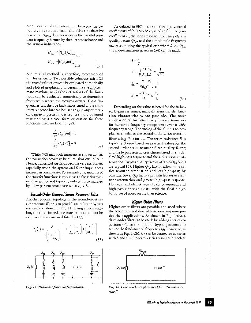
Second-Order Damped Series Resonant Filter Another popular topology of the second-order se- ries resonant filter is to provide an inductor bypass resistance as shown in Fig. 11. Using a little alge- bra, the filter impedance transfer function can be expressed in normalized form by ( 3 3 ) .
As defined in (30), the normalized polynomial coefficients of ( 3 3 ) can be equated to find the gain coefficient A, the series resonant frequency &, the quality factor Qbp, and the simple pole frequency 03,. Also, noting the typical case where R < < Rbp, the approximations given in (34) can be made.
1 A = - ,- L
Depending on the value selected for the induc- tor bypass resistance, many different transfer func- tion characteristics are possible. The main application of this filter is to provide attenuation for harmonic frequency components over a wide frequency range. The tuning ofthis filter is accom- plished similar to the second-order series resonant filter using (34) for a0. The series resistance R is typically chosen based on practical values for the second-order series resonant filter quality factor; and the bypass resistance is chosen based on the de- sired high-pass response and the series resonant at- tenuation. Bypass quality factors of0.5 < Qbp 4 2.0 are typical E>]. Higher Qbp factors allow more se- ries resonant attenuation and less high-pass; by contrast, lower Qbp factors provide less series reso- nant attenuation and greater high-pass response. Hence, a tradeoff between the series-resonant and high-pass responses exists, with the final design being based more on art than science.
Hluher-Order Filters - Higher-order filters are possible and used where the economics and desired harmonic response jus- tify their applications. As shown in Fig. 14(a), a third-order filter can be made by adding a series ca- pacitance C2 to the inductor bypass resistance to reduce the fundamental frequency Ibp losses; or, as shown in Fig. 14(b), C2 can be connected in series with L and sized to form a series resonant branch at
2
Fig. 15. Nth-order filter configurations. Fig. 16. Line reactance placement for a "harmonic- trap."
I I I I I I I I I I I I I I I I I I I I I I I I I I I I I I I I I I I I I I I I I I I I I I I I I I I I I I I I I I I I I I I I I I I I I I I I I I I I I I I I I I I I I I I
@ Iff€ Industry Applicotionr Mogozine Morch/April I 997
I I I I I I I I I I I I I I I I I I I I I I I I I I I I I I I I I I I I I I I I I I I I I I I I I I I I I I I I I I I I I I I I I I I I I I I I I I I I I
I z, ,PCC
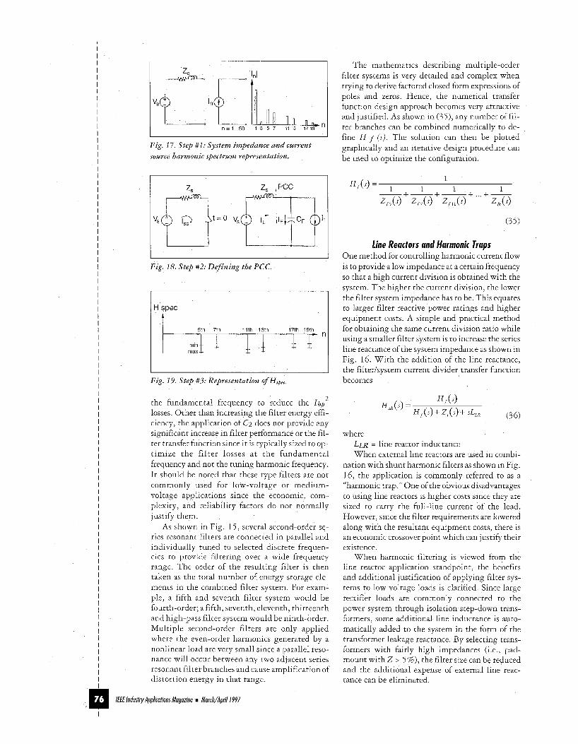
Fig. 17. S tep #1: Sys tem impedance and current source harmonic spectrum representation.
I z, ,PCC ”-ttz0 vsFq+l - I’ Fig. 18. S tep #2: D e f i n i n g the PCC.
H spec I 1
Fig. 19. S tep #3: Representation of HrPec
the fundamental frequency to reduce the Ibp2 losses Other than increasing the filter energy effi- ciency, the application of C2 does not provide any significant increase in filter performance or the fil- ter transfer function since it is typically sized to op- timize the filter losses at the fundamental frequency and not the tuning harmonic frequency. It should be noted that these type filters are not commonly used for low-voltage or medium- voltage applications since the economic, com- plexity, and reliability factors do not normally justify them
As shown in Fig. 15, several second-order se- ries resonant filters are connected in parallel and individually tuned to selected discrete frequen- cies to provide filtering over a wide frequency range The order of the resulting filter is then taken as the total number of energy storage ele- ments in the combined filter system For exam- ple, a fifth and seventh filter system would be fourth-order, a fifth, seventh, eleventh, thirteenth and high-pass filter system would be ninth-order Multiple second-order filters are only applied where the even-order harmonics generated by a nonlinear load are very small since a parallel reso- nance will occur between any two adjacent series resonant filter branches and cause amplification of distortion energy in that range.
The mathematics describing multiple-order filter systems is very detailed and complex when trying to derive factored closed form expressions of poles and zeros Hence, the numerical transfer function design approach becomes very attractive and justified As shown in (35 ) , any number of fil- ter branches can be combined numerically to de- fine H f ( s i The solution can then be plotted graphically and an iterative design procedure can be used to optimize the configuration
- 1
( 3 5 )
fine Reactors and Harmonic Traps One method for controlling harmonic current flow is to provide a low impedance at a certain frequency so that a high current division is obtained with the system The higher the current division, the lower the filter system impedance has to be This equates to larger filter reactive power ratings and higher equipment costs A simple and practical method for obtaining the same current division ratio while using a smaller filter system is to increase the series line reactance of the system impedance as shown in Fig. 16. With the addition of the line reactance, the filterisystem current divider transfer function becomes
where LLR = line reactor inductance When external line reactors are used in combi-
nation with shunt harmonic filters as shown in Fig 16, the application is commonly referred to as a “harmonic trap ” One of the obvious disadvantages to using line reactors is higher costs since they are sized to carry the full-line current of the load However, since the filter requirements are lowered along with the resultant equipment costs, there is an economic crossover point which can justify their existence
When harmonic filtering is viewed from the line reactor application standpoint, the benefits and additional justification of applying filter sys- tems to low voltage loads is clarified Since large rectifier loads are commonly connected to the power system through isolation step-down trans- formers, some additional line inductance is auto- matically added to the system in the form of the transformer leakage reactance By selecting trans- formers with fairly high impedances (1 e , pad- mount with Z > 5 % ) , the filter size can be reduced and the additional expense of external line reac- tance can be eliminated
I€€€ /ndusfry Apphfions Maguzine Morch/Apri/ 1 997
Now that some of the system transfer functions and filter configurations have been discussed, the question of how much filtering is required needs to be answered.
A Passive Harmonic Filfer Design Procedure One of the main goals for outlining an engineering design procedure is to keep it simple $it is going t o be zls&l. With this in mind, and assuming that har- monic filters are required, the following procedure basically consists of obtaining the system informa- tion and building the filterisystem current divider transfer function Hcds(s) based on the applicable IEEE-5 19 distortion limits and harmonic current source spectrum of the rectifier load. Once the fil- ter system impedance transfer function Hf(s ) is op- timized to the system and the design control lim- its, the last step consists ofwriting an engineering specification for the final design. The following steps detail this procedure, and one example is given to show how it can be used in a real-world application.
Step #I: System Data The first step consists of gathering the system im- pedance information and motor drive current source harmonic spectrum. As shown in Fig. 17, the system can be represented as a single-phase Thevenin equivalent and the harmonic spectrum as a simple lumped current source equivalent for a first-order approximation. If more complexity is required in the analysis, the power system can be modeled as a network of impedances taking into account power factor and cable capacitances, and the harmonic sources can be modeled as one or more Norton equivalents connected to a common bus or distributed throughout the network. The detail to which the system is modeled is ultimately a function of the particular engineering require- ment. The main goal is to control the distortion so that when actual field measurements are taken they meet the limits and no adverse system distortions result.
Step #2: Define the PCC If the IEEE-5 19 limits are to be used as the design guidelines, the PCC where the limits are to be ap- plied needs to be defined. As shown in Fig. 18, once the PCC is defined, the short circuit ratio (lSc/h,) of the system and harmonic generating source maximum demand load current can be cal- culated from (37) and (38). The filter system cur- rent has been included to account for its contribution at 60 Hz.
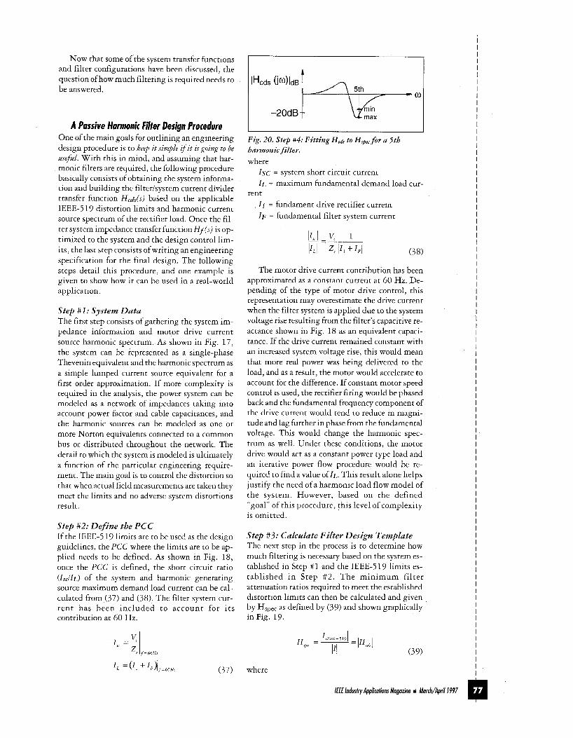
Fig. 20. step #4: Fitting Hcds t o H,, for a 5th harmonic filter. where
Isc = system short circuit current I L = maximum fundamental demand load cur-
I 1 = fundament drive rectifier current I F = fundamental filter system current
rent
The motor drive current contribution has been approximated as a constant current at 60 Hz. De- pending of the type of motor drive control, this representation may overestimate the drive current when the filter system is applied due to the system voltage rise resulting from the filter’s capacitive re- actance shown in Fig. 18 as an equivalent capaci- tance. If the drive current remained constant with an increased system voltage rise, this would mean that more real power was being delivered to the load, and as a result, the motor would accelerate to account for the difference. If constant motor speed control is used, the rectifier firing would be phased back and the fundamental frequency component of the drive current would tend to reduce in magni- tude and lag further in phase from the fundamental voltage. This would change the harmonic spec- trum as well. Under these conditions, the motor drive would act as a constant power type load and an iterative power flow procedure would be re- quired to find a value of IL. This result alone helps justify the need ofa harmonic load flow model of the system. However, based on the defined “goal” of this procedure, this level of complexity is omitted.
Step #S: Calculate Filter Design Template The next step in the process is to determine how much filtering is necessary based on the system es- tablished in Step #1 and the IEEE-519 limits es- tablished in Step #2 . The minimum filter attenuation ratios required to meet the established distortion limits can then be calculated and given by Hspec as defined by (39) and shown graphically in Fig. 19.
I I I I I I I I I I I I I I I I I I I I I I I I I I I I I I I I I I I I I I I I I I I I I I I I I I I I I I I I I I I I I I I I
(37) where I m /E€ Industry Applications Magozine March/Apri/ I997
I I I I I I I I I I I I I I I I I I I I I I I I I I I I I I I I I I I I I I I I I I I I I I I I
I I E E E - ~ ~ ~ = Applicable IEEE-5 19 current dis-
I = Harmonic current spectrum based on I L The maximum and minimum levels in Fig 19
are intended to indicate a design range based on changing system conditions and filter component tolerance variations The maximum design is based on both filter overloading and system impedance changes (i.e , an increased system impedance) The minimum design is based on meeting the IEEE- 519 limits. It should be noted that when using (39) , if the harmonic spectrum is scaled in percent based on I L as calculated in (37) , then Hspec can eas- ily be calculated directly from the IEEE-519 cur- rent distortion tables It should also be noted that if the filter size is changed during the design process, as is usually the case, I L and Hspec will both change
Since the IEEE-5 19 current distortion limits are based on the maximum demand load current I L , the distortion current a harmonic producing load is allowed to inject into the power system is not constant It is dynamic, and it changes with load This tends to make the application of IEEE- 519 tedious to work with from a modeling and compliance standpoint because the actual system loading tends to be composed of several random variables all ofwhich cannot be accounted for dur- ing design When compliance is verified by actual harmonic measurements, the maximum demand can be measured and the applicable IEEE-5 19 limits can be applied However, the actual maxi-
tortion limit spectrum mum load will usually be different from what was modeled during the design process Therefore, common sense and experience are both required when applying the IEEE-5 19 current distortion limits for the purposes of filter design and meas- urement compliance
Step #4: F i t Filter to System, H f und Hcds Step #4 consists of configuring a filter system by building a filter impedance transfer function Hfir) using a combination of first, second and third- order filter sections H f ( s j is then used to build H,ds(s) and plotted graphically with the filter de- sign template H,pec to determine IEEE compliance under both ideal and component tolerance varia- tions An iterative procedure is used to optimize H f (s) and Hcds(s) based on the consideration ofpracti- cal operating conditions and economic alterna- tives. For example, if a single fifth harmonic filter was being designed, Fig 20 shows graphically how the transfer functions can be used together
Step #5: Check Loadings a n d Modeling As a last step in the design process, after the filter system is optimized and fit to the system, actual components need to be selected based on available and practical power system apparatus At that point, the filter component ratings need to be com- pared to the harmonic loadings calculated from the model and appropriate design margins applied. This last step is typically done using a computer-
ALTERNATE SOURCE
PRIMARY SOURCE
CONDUCTOR TYPE
A 750MCM AL UNDERGROUND 6" DUCT BANK
A ~ ~ ~ M c M ACSR OVERHEAD
n 3 9 7 M C M AL OVERHEAD
FAULT LEVELS A PROVIDED BY
4 ' 4 '
;i: VFD
FUTURE FUTURE FUTURE
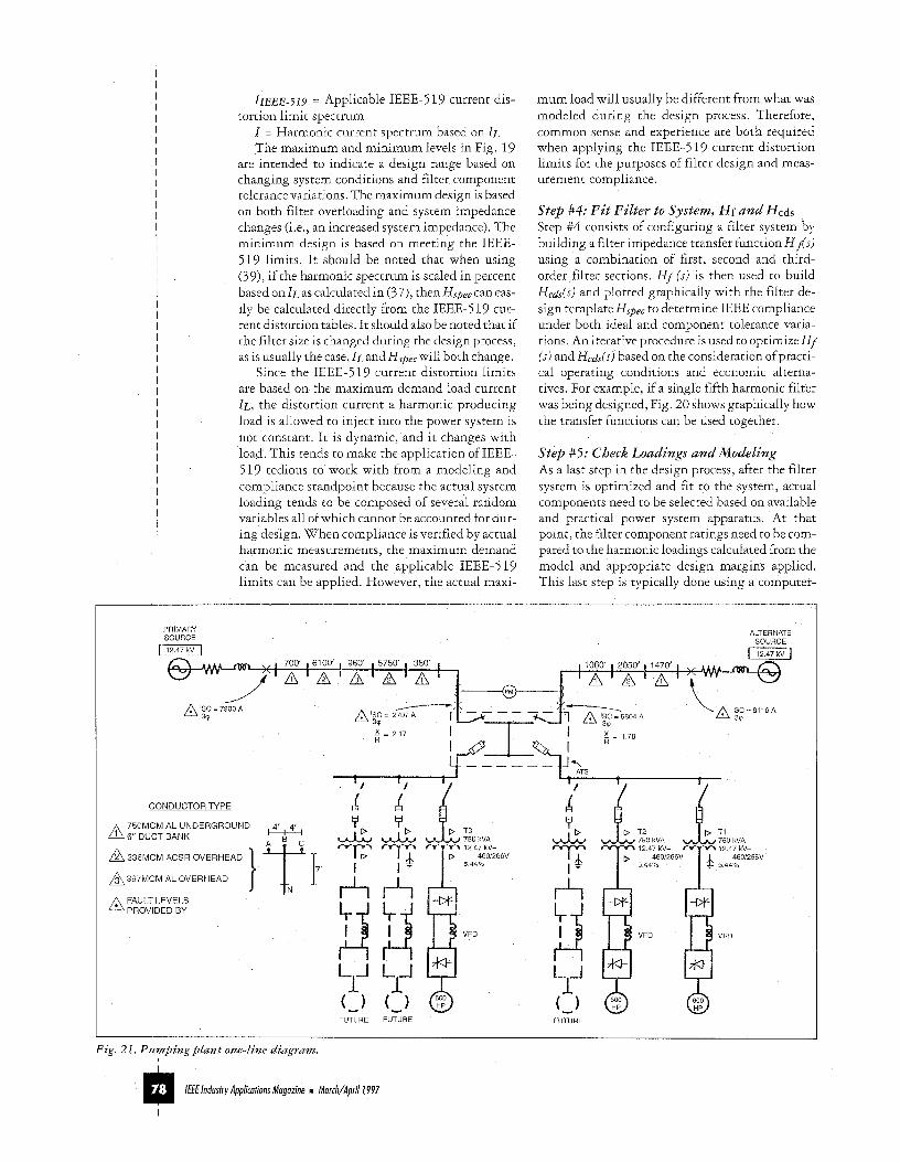
Fig. 21. P u m p i n g plant one-line d iagram.
/E€ lndusfry Applicutions Muguzine I Murch/Aprili997
I
simulated model of the system considering various worst-case harmonic loading conditions and com- ponent tolerance variations to verify proper opera- tion VHARM, HARMFLO, and PSPICE are typical software packages which can be used for this purpose.
This completes the filter design process as far as meeting the current distortion limits are con- cerned There are still many other factors that need to be considered before a technical specifica- tion can be written, but their detailed discussion here is beyond the scope of this article. Some of these include (1) filter reliability, (2) 1 T product calculations for telephone interference, (3) volt- age distortion conditions, (4) filter equipment standards, ( 5 ) quality control, (6) filter configura- tions and switching sequences, (7) filter system switching control, (8) system voltage rise consid- erations, (9) allowable component tolerance varia- tions and design margins, (10) overcurrent and overload protection and indication, (1 1) voltage and current imbalance protection, (12) compo- nent materials, ratings, and construction, (1 3) mechanical and physical considerations such as component layout and cooling, (14) commission- ing and acceptance testing, (15) damping and tuning adjustments and methods, (16) grounding and zero sequence performance, etc.
A Transfer Function Application Example As shown in Fig 2 1, a pumping plant is served by two 12 47 kV distribution feeders through an automatic transfer switch (ATS) arrangement with a weaker primary source and a stronger alternate source from two separate utility substations. The plant has facilities for six 600 hp variable frequency motor drives (VFD), with three planned for the fu- ture. A typical current waveform and harmonic spectrum of a single VFD is shown in Fig 2 1 Each drive is connected to a separate step-down power transformer, each with alternating wye/delta sec- ondary winding configurations to achieve har- monic component cancellation between VFDs The operation of the plant can have any one pump on at a time so the benefits of harmonic reduction from the transformer phase shifting is dependent on the coincidence of the loads It has been re- quested by the utility that the waveform distortion be controlled so that IEEE-519 limits are met when the primary source feeder is in operation Be- cause of the characteristics of the plant, one pump is normally operated alone during light load condi- tions As the loading increases, the other two pumps are used as needed
In this particular example, because of the opeta- tion of the individual pumps, separate filter sys- tems applied at each VFD are being considered as one possible solution The main objective is to de- sign an individual filter system for each VFD recti- fier and estimate the equipment costs
I I I I
800. I I i
-
ik -
0 - -
-800 I I I 0 0.01 66
.3
linl
li, I -
n -
0 0 n 80
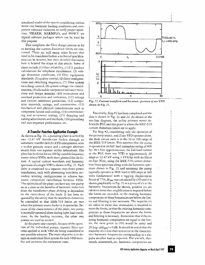
Fig. 22. Current waveform and harmonic spectrum of one VFD shown in Fig. 21,
Essentially, Step # 1 has been completed and the data is shown in Fig. 21 and 22. As shown in the one-line diagram, the utility primary meter de- fines the PCC and this point is where the IEEE-5 19 current distortion limits are to apply.
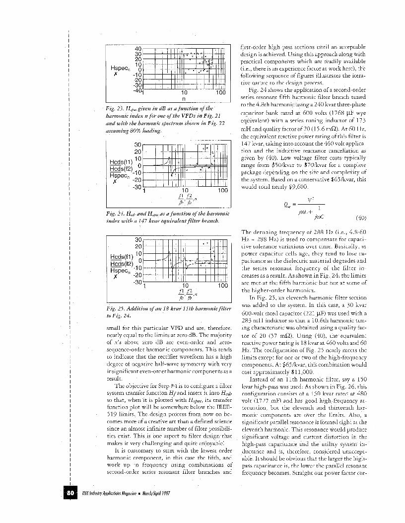
For Step # 2 , considering only the operation of the primary source, and if one VFD operates alone, the short circuit ratio is in the 50 to 100 range of the IEEE-519 limits. This assumes that the pump is operated at its full-load nameplate rating of 600 hp. As a first approximation, the full-load current at the PCC from one VFD is approximately 28 amps at 12.47 kV using 1 kVAIhp with no filters on-line. Next, using the IEEE-519 cuttent distor- tion limit spectrum along with the harmonic spec- trum shown in Fig. 22 and assuming the pump typically operates at 80% load or 600 amps at 460 volts fundamental with a lagging displacement factor of 77%, Hspec was calculated by (39) and it is shown graphically in Fig. 23 as agroup ofx's at the harmonic frequencies.As shown, positive x's are taken to mean that amplification is required before the limits are exceeded, or the existing harmonic components at those frequencies are below the lim- its and filtering is not necessary. The negative x's are taken to mean that attenuation is tequired to meet the limits, or that the existing harmonic com- ponents at those frequencies are above the limits and filtering is necessary. Remember that if the ex- isting harmonic components are equal to the lim- its, the ratio given in (39) would be unity and 20.L0glo(Hspec) = 0 dB. It should be noted that the majority ofx's less than zero occur at the character- istic harmonic frequencies corresponding to a six- pulse rectifier load as expected. The seventh, thir- teenth, nineteenth, etc. harmonic components are
I I I I I I I I I I I I I I I I I I I I I I I I I I I I I I I I I I I I I I I I I I I I I I I I I I I I I I m Iff€ Industry Applications Magazine March/Aprill997
I
I I I I I I I I I I I I I I I I I I I I I I I I I I I I I I I I I I I I I I I I I I I I I I I I I I I I I I I I I I I I I I I I I I I I I I I I I I I I I I I I I I I I I I I I I I I
40 301 20 10
HsPecn 0 ty -10
-20 -30 1 I I I I I I I I I
-404 ' 1 1 ' ' 1 1 1 10 100 n
Fig. 2?. Hspc given in dB as a function of the harmonic index n for one of the VFDs in Fig. 21 and with the harmonic spectrum shown in Fig. 22 assuming 80% loading.
30 20 10 - Hcds(f1)
Hspec, H c d m , 0
x -20 I I I I I I I I I
10 100 -30\ I ' I ' ' ' ' I _ - fl f 2 , n f a ' f b
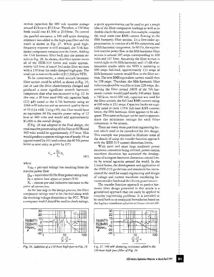
Fig. 24. Hcdi and H,, as a function of the harmonic index with a 147 kvar equivalent filter branch.
30 20 10 Hcds(f1)
Hspec, W S ( f 2 ) - , 0
)r -20 I I I I I I I I I
-30; ' 10 100 _ _ f l f2 f b , f b , n
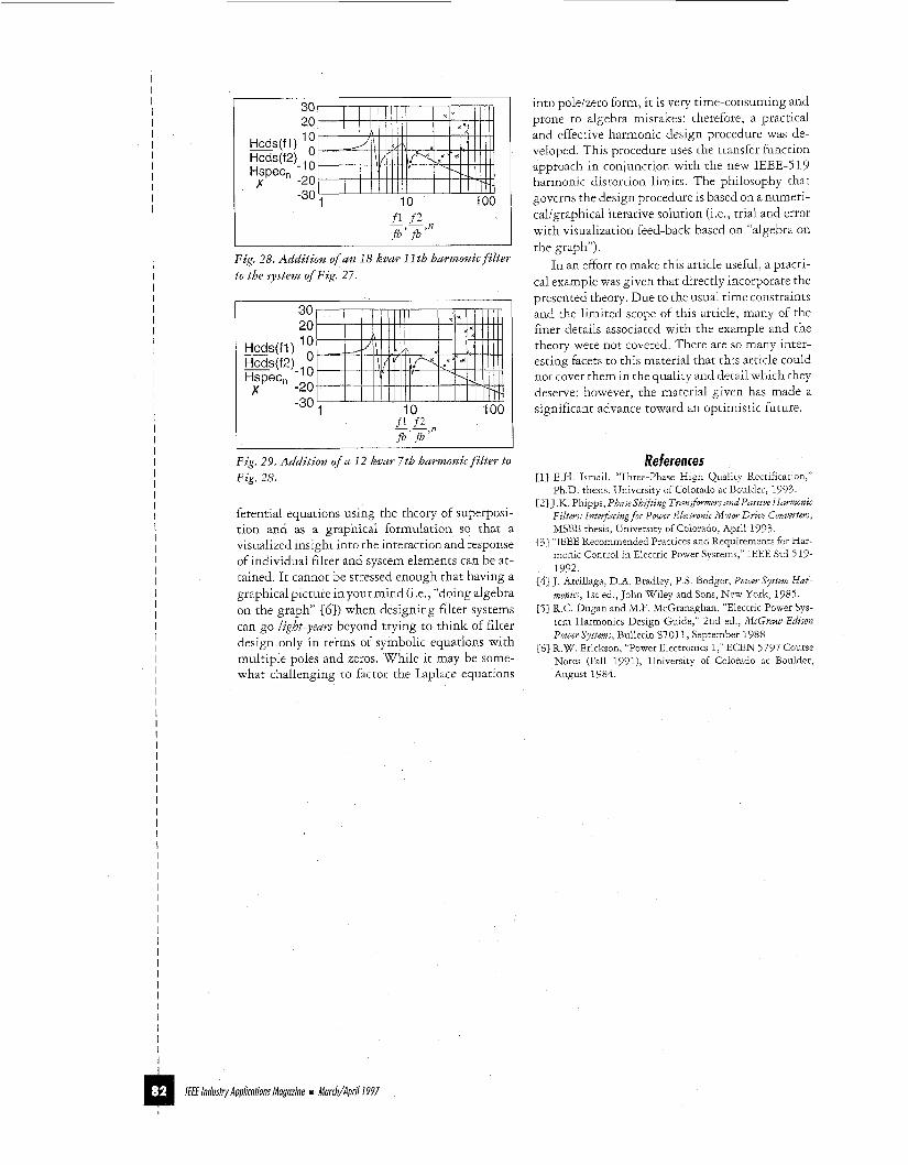
Fig. 25. Addition of an 18 kvar 1 Ith harmonic filter t o Fig. 24.
small for this particular VFD and are, therefore, nearly equal to the limits at zero dB. The majority of x's above zero dB are even-order and zero- sequence-order harmonic components. This tends to indicate that the rectifier waveform has a high degree of negative half-wave symmetry with very insignificant even-order harmonic components as a result.
The objective for Step #4 is to configure a filter system transfer function Hfand insert it into Hcds so that, when it is plotted with Hspec, its transfer function plot will be somewhere below the IEEE- 519 limits. The design process from now on be- comes more of a creative art than a defined science since an almost infinite number of filter possibili- ties exist This is one aspect to filter design that makes it very challenging and quite enjoyable'
It is customary to start with the lowest order harmonic component, in this case the fifth, and work up in frequency using combinations of second-order series resonant filter branches and
/E€€ lndustry Applicutiuns Muguzine m Murch/Apri/ I997
first-order high-pass sections until an acceptable design is achieved. Using this approach along with practical components which are readily available (i e , there is an experience factor at work here), the following sequence of figures illustrates the itera- tive nature to the design process
Fig. 24 shows the application of a second-order series resonant fifth harmonic filter branch tuned to the 4 8th harmonic using a 240 kvar three-phase capacitor bank rated at 600 volts (1768 pF wye equivalent) with a series tuning inductor of 173 mH and quality factor of 20 (1 5 6 mQ) At 60 Hz, the equivalent reactive power rating of this filter is 147 kvar, taking into account the 460 volt applica- tion and the inductive reactance cancellation as given by (40). Low voltage filter costs typically range from $5O/kvar to $iO/kvar for a complete package depending on the size and complexity of the system. Based on a conservative $65/kvar, this would total nearly $9,600
,WY I
j W C (40)
The detuning frequency of 288 Hz (i e , 4 8 60 Hz = 288 Hz) is used to compensate for capaci- tive tolerance variations over time Basically, as power capacitor cells age, they tend to lose ca- pacitance as the dielectric material degrades and the series resonant frequency of the filter in- creases as a result. As shown inFig. 24, the limits are met at the fifth harmonic but not at some of the higher-order harmonics
In Fig. 25, an eleventh harmonic filter section was added to the system In this case, a 30 kvar 600-volt rated capacitor (221 pF) was used with a 283 mH inductor so that a 10 6th harmonic tun- ing characteristic was obtained using a quality fac- tor of 20 (57 mQ). Using (40), the equivalent reactive power rating is 18 kvar at 460 volts and 60 Hz The configuration of Fig 25 nearly meets the limits except for one or two of the high-frequency components. At $65/kvar, this combination would cost approximately $1 1,000
Instead of an 11th harmonic filter, say a 150 kvar high-pass was used. As shown in Fig. 26, this configuration consists of a 150 kvar rated at 480 volt (1727 mF) and has good high-frequency at- tenuation, but the eleventh and thirteenth har- monic components are over the limits Also, a significant parallel resonance is formed right at the eleventh harmonic This resonance would produce significant voltage and current distortion in the high-pass capacitance and the utility system in- ductance and is, therefore, considered unaccept- able It should be obvious that the larger the high- pass capacitance is, the lower the parallel resonant frequency becomes. Straight out power factor cor-
rection capacitors for 480 volt systems average around $5lkvar to $12/kvar. Therefore, a 150 kvar bank would cost $1,500 at $10/kvar. To control the parallel resonance, a 100 mi2 series damping resistance was added to the high-pass filter and the result is shown in Fig. 27. While good high- frequency response is still attained, the 11 th har- monic component remains over the limits. Adding the 11 th harmonic filter back into the system re- sults in Fig. 28. As shown, this filter system meets all of the IEEE-519 limits and totals approxi- mately 165 kvar of tuned 2nd-order filter sections with a 150 kvar 1st-order damped high-pass. The total cost is now on the order of (4 12,500 per VFD.
To be conservative, a small seventh harmonic filter section could be added, as shown in Fig. 29, just in case the drive characteristics changed and produced a more significant seventh harmonic component than what was mcasured in Fig. 22. In this case, a 20 kvar rated 600 volt capacitor bank (221 pF) tuned to the 6.7th harmonic using an 1064 m H inductor and an assumed quality factor of 20 (134 ma) . Using (do), this filter would have an equivalent 60 Hz reactive power rating of 12 kvar at 460 volts and would add approximately $1,000 to the overall design.
If Fig. 28 was adopted as the final design, the total reactive power rating of the filter at 60 Hz and 460 volts would be approximately 3 15 kvar. This would produce a system voltage rise of nearly 3% as approximated by (41) and correct the 60 Hz power factor to near unity as given by (37).
(41)
where
reactive power flow V,;,, = per-unit voltage rise resulting from the
Qeq = equivalent 60 Hz filter power rating (var) s b = system base apparent power (VA) X , = system per unit inductive reactance to the
point of connection As the last step in the design process, the filter
component ratings need to be checked along with the resulting voltage distortion at the PCC. While a computer model should be used to check ratings,
a quick approximation can be used to get a rough idea of the filter component loadings as well as to double-check the computer. For example, consider the total worst-case RMS current flowing in the fifth harmonic filter section. To a first-order ap- proximation, it consists of a 60 Hz component and a fifth harmonic component. At 60 Hz, the equiva- lent reactive power flow in the fifth harmonic filter section is around 185 amps corresponding to 460 volts and 147 kvar. Assuming the filter section is tuned right to the fifth harmonic and -15 dB of at- tenuation results while the VFD is operating at 600 amps full-load, approximately 133 amps of fifth harmonic current would flow in the filter sec- tion. The true RMS equivalent current would then be 228 amps. Therefore, the fifth harmonic filter inductors should be rated for at least 228 amps. As- suming the filter carried 100% of the 5th har- monic current would yield nearly 246 amps. Since a 240 kvar, rated 600 volt, capacitor was used for the filter section, the full load RMS current rating at 600 volts is 23 1 amps. Capacitor banks are typi- cally rated to carry 135% full-load RMS current; hence, the fifth harmonic filter appears to be ade- quate. This same technique can be used to approxi- mate the minimum ratings for each filter component in the system.
There are many more practical engineering fac- tors which need to be considered for this design. This example was presented to illustrate some of the details of using the transfer function approach with the IEEE-5 19 current distortion limits.
With more and more large nonlinear power electronic converters being utilized, power system waveform distortion has warranted the develop- ment of stringent harmonic distortion control lim- its by several agencies around the world. In the United States, the development and application of the IEEE-5 19 guidelines and standards has neces- sitated the need for sound engineering and design of voltage and current waveform interfacing be- tween rectifier loads and the electric power source.
The transfer function approach to passive har- monic filter design presented in this article is a generalized approach that can easily be applied to rvrryday engineering problems. IL is intended to be used both as an analytical formulation based on the Laplace transform solution to linear circuit dif-
30 20 10 - Hcds(f1)
Hspec, - H c d W , 0
8 -20 I I N l l l l l 10 100 -30; ' ' I " ' I "
~~ fl f2,, fi' fi
Fig. 26. Addition of a 150 knar high-pass to Fig. 24.
30 20 10 - Hcds(f1)
Hspec, WS(f2)- , 0
-20 -30 7 10 100
8
_ _ fl f2,, f h ' f b
Fig. 27. 100 rnW dumbing resistance added to the 1,50 kvar high-pass filter of Fig. 26.
I I I I I I I I I I I I I I I I I I I I I I I I I I I
I I I I I I I I I I
I I I I I I I I I I I I I I I I I I I I I I I I I I I I I I I I I m /E€€ industry Applications Mogozine Morch/Apd I997
I I I I I I I I I I I I I I I I I I I I I I I I I I I I I I I I I I I I I I I I I I I I I I I I I I I I I I I I I I I I I I I I I I I I I I I I I I I I I I I I I I I I I I I I I I I I
30 20 10 Hcds(f1)
Hspec, -20
10 100 -30; ' " " " ' ' ' I " ' " '
Fig. 28. Addition of an 18 kvar 11 th harmonic filter t o the system of Fig. 27.
30 20 10 W s ( f 1 )
Hcds(f2)-, 0
x -2Ot-H Hspec,
10 100 -30 _ _ si f 2 $ fb' fb
into poleizero form, it is very time-consuming and prone to algebra mistakes; therefore, a practical and effective harmonic design procedure was de- veloped. This procedure uses the transfer function approach in conjunction with the new IEEE-S 19 harmonic distortion limits. The philosophy that governs the design procedure is based on a numeri- caligraphical iterative solution (i.e., trial and error with visualization feed-back based on "algebra on the graph").
In an effort to make this article useful, a practi- cal example was given that directly incorporate the presented theory. Due to the usual time constraints and the limited scope of this article, many of the finer details associated with the example and the theory were not covered. There are so many inter- esting facets to this material that this article could not cover them in the quality and detail which Ehey deserve; however, the material given has made a significant advance toward an optimistic future.
Fig. 29. Addition of a 12 kvar 7th harmonic filter to Fig. 28,
ferential equations using the theory of superposi- tion and as a graphical formulation so that a visualized insight into the interaction and response of individual filter and system elements can be at- tained It cannot be stressed enough that having a graphical picture in your mind (I e , "doing algebra on the graph" [b]) when designing filter systems can go Izght-years beyond trying to think of filter design only in terms of symbolic equations with multiple poles and zeros. While it may be some- what challenging to factor the Laplace equations
References [l] E.H. Ismail, "Three-phase High Quality Rectification,"
Ph.D. thesis, University of Colorado at Boulder, 1993. 121 J.K. Phipps, PhaseShrfting TransfomzersandPassive Harmonrc
Filters: Interfucmg for Power Electronic Motor Drive Converters, MSEE thesis, University of Colorado, April 1993.
131 "IEEE Recommended Practices and Requirements for Har- monic Control in Electric Power Systems," IEEE Std 5 19- 1992.
[4] J. Arrillaga, D.A. Bradley, P.S. Bodger, Power system Har- monia, 1st ed., John Wiley and Sons, New York, 1985.
[ 5 ] R.C. Dugan and M.Z. McGranaghan, "Electric Power,Sys- tem Harmonics Design Guide," 2nd ed., McGruw-Edison Pwer Systems, Bulletin 87011, September 1988.
161 R.W. Erickson, "Power Electronics 1," ECEN 5797 Course Notes (Fall 1991), University of Colorado at Boulder, August 1984.
/€€E Industry App/ications Mugazine m Murch/Apri/ I 997