A touch of Class, The Windom and thebackwoodsbasic.weebly.com/.../j_pole_antenna_handbook_.pdfC =...
9
These documents are f ree to Amateur Radio Operator's and Not-f or-Prof it organizations. Permission to display elsewhere requires permission of the author(s) and a permit number; Permit number request to display document (include f ile title). All credits and titles must remain a part of the original file or document. Each f ile is (C) and/or reg TM of the author. BUXCOMM, agents, or employees, are not responsible f or errors or ommissions. Use of inf ormation contained in each f ile is at your own risk. Serving HAM Radio since 1959, On the Web Since 1995 Order Toll Free Monday through Friday, 9 amto 5 pm, 1 800 726 2919 or 1 866 300 1969, (C) 1988-2012 ALL Times, Eastern NO MINIMUM ORDERS, Same Day Shipping, except Sunday and Holidays BUXCOMM Corporation 115 LUENBURG DRIVE EVINGTON, VIRGINIA 24550 BUXCOMM Tech Support is by expert ARO's, Technicians and Engineers. *Tech Support; Email; [email protected] CLICK HERE for on-line Printable Order Form. We accept: A touch of Class, The Windom and the J-POLE By Glynn E. "Buck" Rogers Sr (68 years as K4ABT) above " When you have reached perfection, anything more becomes a point of diminishing returns." Enough said! It's difficult to improve on perfection. J-Pole J Pole Antenna Handbook Home Page 12/3/2014 http://www.buxcomm.com/jpoles4ever.htm 1 / 9
Transcript of A touch of Class, The Windom and thebackwoodsbasic.weebly.com/.../j_pole_antenna_handbook_.pdfC =...

These documents are free to Amateur Radio Operator's and Not-for-Prof it organizations. Permission to display elsewhere requires permission of the author(s)
and a permit number; Permit number request to display document (include f ile title). All credits and titles must remain a part of the original file or document.
Each f ile is (C) and/or reg TM of the author. BUXCOMM, agents, or employees, are not responsible for errors or ommissions.
Use of information contained in each f ile is at your own risk.
Serving HAM Radio since 1959, On the Web Since 1995
Order Toll Free Monday through Friday, 9 am to 5 pm, 1 800 726 2919 or 1 866 300 1969, (C) 1988-2012 ALL Times, EasternNO MINIMUM ORDERS, Same Day Shipping, except Sunday and Holidays BUXCOMM Corporation 115 LUENBURG DRIVE EVINGTON, VIRGINIA 24550
BUXCOMM Tech Support is by expert ARO's, Technicians and Engineers. *Tech Support; Email; [email protected] HERE for on-line Printable Order Form.
We accept:
A touch of Class, The Windom and the J-POLEBy Glynn E. "Buck" Rogers Sr (68 years as K4ABT)
above
"When you have reached perfection, anything more becomes a point of diminishing returns." Enough said!
It's difficult to improve on perfection.
J-Pole
J Pole Antenna Handbook Home Page 12/3/2014
http://www.buxcomm.com/jpoles4ever.htm 1 / 9
Windom
to know the difference and for heavens sake, DO NOT attempt building a J-Pole for seventy-five (75) meters.
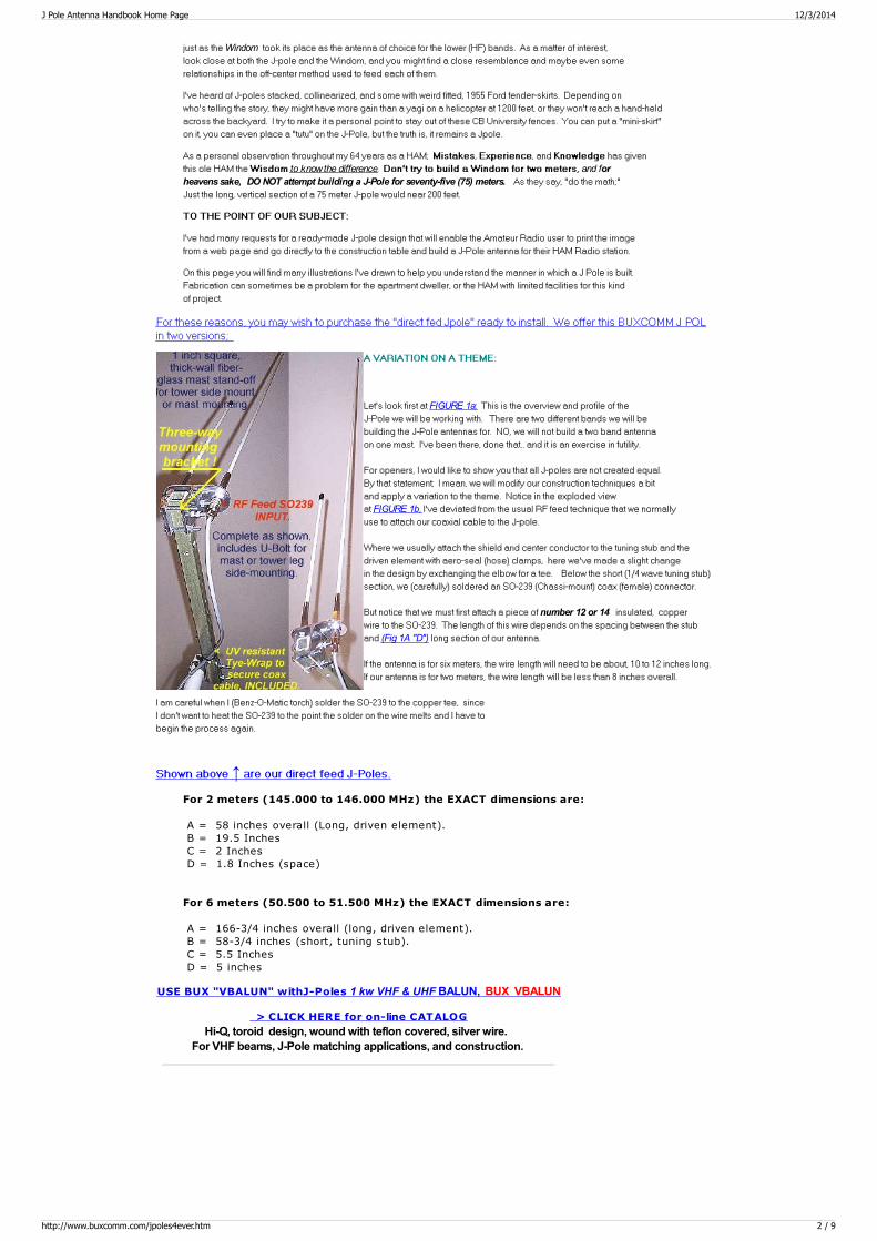
FIGURE 1a
FIGURE 1b
number 12 or 14
(Fig 1A "D")
↑For 2 meters (145.000 to 146.000 MHz) the EXACT dimensions are:
A = 58 inches overall (Long, driven element). B = 19.5 Inches C = 2 Inches D = 1.8 Inches (space)
For 6 meters (50.500 to 51.500 MHz) the EXACT dimensions are:
A = 166-3/4 inches overall (long, driven element). B = 58-3/4 inches (short, tuning stub). C = 5.5 Inches D = 5 inches
USE BUX "VBALUN" withJ-Poles 1 kw VHF & UHF BALUN, BUX VBALUN
> CLICK HERE for on-line CATALOGHi-Q, toroid design, wound with teflon covered, silver wire.
For VHF beams, J-Pole matching applications, and construction.
J Pole Antenna Handbook Home Page 12/3/2014
http://www.buxcomm.com/jpoles4ever.htm 2 / 9
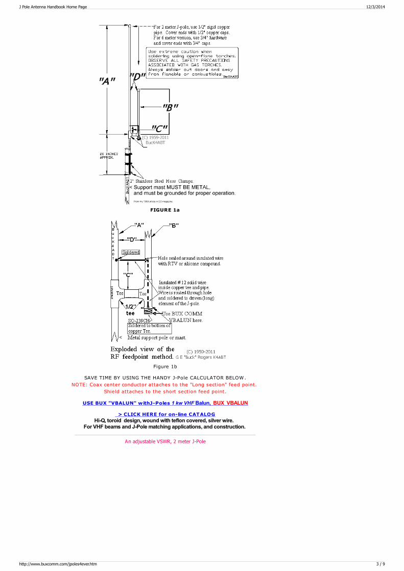
FIGURE 1a
Figure 1b
SAVE TIME BY USING THE HANDY J-Pole CALCULATOR BELOW.NOTE: Coax center conductor attaches to the "Long section" feed point.
Shield attaches to the short section feed point.
USE BUX "VBALUN" withJ-Poles 1 kw VHF Balun, BUX VBALUN
> CLICK HERE for on-line CATALOGHi-Q, toroid design, wound with teflon covered, silver wire.
For VHF beams and J-Pole matching applications, and construction.
An adjustable VSWR, 2 meter J-Pole
J Pole Antenna Handbook Home Page 12/3/2014
http://www.buxcomm.com/jpoles4ever.htm 3 / 9

BUX VBALUN should be installed at the antenna feed point, or where the coax or feed-lineattaches to the J-Pole antenna. BUX BALUNs are used to connect balanced antennas tounbalanced transmission lines, such as coax cable. Their primary purpose is to preventantenna (RF) currents from flowing down the outside of the cable (VSWR). Anotherfunction of the BUX BALUN41 is to match the impedance of an unbalanced coax to theantenna feed point. BUX LISO BALUNS may also be used as “line isolators” anywherealong the cable to prevent the destructive influence of induced RF currents (VSWR). BUX 1:1 BALUNs are current BALUNs. They consist of several large, number 73, ferritecores.
CLOSE UP of the alternative coax feed method.
Use BUX VBALUN to couple coaxial cable to J-Pole.
My Hardware J-Poles from 1959 & BUXCOMM J2JAY (1995)
J Pole Antenna Handbook Home Page 12/3/2014
http://www.buxcomm.com/jpoles4ever.htm 4 / 9

In the early days of packetRadio, we used this Jpole as anIndoor antenna to
hit the local Packet Nodes (PacketRepeater). Unbelievableperformance when
suspended vertically near a window or off the patio. Gain is3.7 dbi MOL.
A=Benz-O-Matic propane torch; B=Lead-Free solder; C=Tapemeasure: D=Tubing cutter; E=Sharpie marking pen; F=Solder
Paste; G=1/2 inch copper caps; H=Hardcopy of the above
J Pole Antenna Handbook Home Page 12/3/2014
http://www.buxcomm.com/jpoles4ever.htm 5 / 9
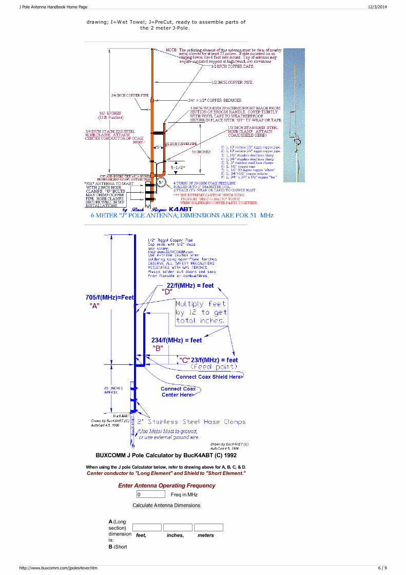
drawing; I=Wet Towel; J=PreCut, ready to assemble parts ofthe 2 meter J-Pole.
BUXCOMM J Pole Calculator by BucK4ABT (C) 1992
When using the J pole Calculator below, refer to drawing above for A, B, C, & D.Center conductor to "Long Element" and Shield to "Short Element."
Enter Antenna Operating Frequency0 Freq in MHz
Calculate Antenna Dimensions
A (Longsection)dimensionis:
feet, inches, meters
B (Short
J Pole Antenna Handbook Home Page 12/3/2014
http://www.buxcomm.com/jpoles4ever.htm 6 / 9
B (Shortsection)dimensionis:
feet, inches, meters
C (Feedpoint)dimensionis:
feet, inches, meters
D(Spacing)dimensionis:
feet, inches, meters
Inside (spacing) dimensions are metal to metal measurements, NOT center to center.
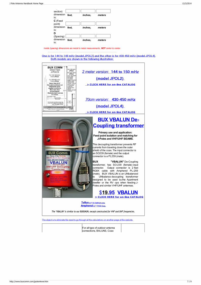
2 meter version:
> CLICK HERE for on-line CATALOG
70cm version:
> CLICK HERE for on-line CATALOG
BUX VBALUN De-Coupling transformer
Primary use and application:Feed point isolation and matching for
J-Poles and VHF/UHF BEAMS.
This decoupling transformer prevents RFcurrents from traveling down the outershield of the coax. The input connector isan SO239 (female) and the outputconnector is a PL259 (male).
BUX "VBALUN" De-Couplingtransformer, has SO-239 (female) inputconnector. Output connector is 2 feetRG8X cable with Amphenol PL-259(male). BUX VBALUN is an UNbalancedto UNbalance decoupling transformerdesigned to be used by the Apartmentdweller or the RV ops when feeding J-Poles and similar VHF/UHF antennas.
$19.95 VBALUN > CLICK HERE for on-line CATALOG
Teflon ®™ E I DuPont corp.
Amphenol ®™ TYCO Corp.
The "VBALUN" is similar to our BUXUNUN, except constructed for VHF and UHF frequencies.
For all type of outdoor antennaconnections, BALUNS, Coax
J Pole Antenna Handbook Home Page 12/3/2014
http://www.buxcomm.com/jpoles4ever.htm 7 / 9
connectors, coax bulkhead entrypanels and more. Use Coax-Seal®to protect any outdoor connection orconnector. Coax-Seal is made of anon-conductive, non-contaminatingwaterproof material that remainsflexible at any temperature from -30°to 180°F. Coax connectors that arenot waterproof or have exposedsolder joints can weaken fromoxidation ! Coax-Seal is superior toelectrical tape or vinyl sealants formoisture protection. Each box ofCoax-Seal contains (60 inches x 1/2inch) five feet and will protect ten(10) connectors.
2.95 Order Code CS104
CLICK HERE to buy COAXSEAL
CAT#, CS104, For alltype of outdoor antennaconnections, BALUNS,Coax connectors, coaxbulkhead entry panelsand more.
TEMPERATURE CONTROLLEDSOLDERING STATION 50W 350 - 900° F
Features :manual temperature settingelectronic temperature controlpower-on LED indicationwith grounded output Specifications :heater power for soldering iron: 50Wtemperature variable control: 375-900°F
voltage supply: 115VACweight: 2.65 lbs.dimensions: 7 1/4" x 3 31/32" x 3 1/2"input power: 50VA max.
$ 24.90 Order VTSS5
> CLICK HERE for Tools & Solder Stations
The "Windom Antenna" was described by Loren G. Windom inQST magazine, September 1929. Pages 19 through 22. Loren Windom, W8GZ, was first to reveal the antenna to the radioamateur community by describing the antenna in the September1929 issue of QST. It was by Windom's name that the antennabecame known. The Windom antenna is an off-center fed dipolewith an unbalanced coax feedline.
In 1937, the Windom was first described as a compromisemultiband antenna. The antenna can be employed on 160, 80, 40, 20 and 10m withconsiderable, though acceptable levels of VSWR. What became perhaps the mostpopular multiband Windom design of all, was the German-made Fritzel FD4 antenna,described by the late Dr. Fritz Spillner1, DJ2KY, in 1971. It had the samedimensions as the multiband Windom antenna, but fitted with a 200Ω (4:1) balun atits feedpoint and fed with coax.
Today, many radio amateurs are using multiband Windom antennas with more thansatisfactory results. It would not be without reason that Windom antennas are beingemployed during IARU HF World Championships! and most of all, by "high-stake-contests." Perhaps many young hams ignore the multiband Windom antennabecause of its sheer simplicity and may be thinking it is too good to be true. Thecomplexity of feeding other dipoles and doublets, the losses in dipoles with traps andthe esoteric marketing of some other antennas seem to appeal to them more.
For more J-Pole information, CLICK HERE:
INDEX to our web pages
Serving HAM Radio since 1959, On the Web Since 1992Order Toll Free Monday through Friday, 9 am to 5 pm, 1 800 726 2919 or 1 866 300 1969, Saturday 9 AM to 2 PM Eastern Time
NO MINIMUM ORDERS, Same Day Shipping, except Sunday and Holidays BUXCOMM Corporation 115 LUENBURG DRIVE EVINGTON, VIRGINIA 24550
BUXCOMM Tech Support is by expert Technicians and Engineers. *Tech Support; Email; [email protected]
Visit one of our websites on the WorldWideWeb
amateuradio.org buckscom.com buckscomm.com
BUXCLUB.ORG BUXCOMM.COM BUXCOMM.NET
BUXCOMM.ORG BUXCOMMCO.COM BUXHAMPARTS.COM
BUXHAMSALES.COM BUXHAMSTORE.COM COMMPARTS.COM
J Pole Antenna Handbook Home Page 12/3/2014
http://www.buxcomm.com/jpoles4ever.htm 8 / 9

COMMPARTS.NET COMMPARTS.ORG EVERYTHINGUNDERTHESUNONLINE.COM
HAMANTENNAS.NET HAMANTENNAS.ORG HAMRADIOEXPERT.COM
hamradioexperts.com hamradioexpress.com hamradiogeek.com
HAMRADIOPARTS.NET JACOMM.COM JEANSHOBBIES.COM
K4ABT.COM PACKETRADIO.COM PACKETRADIO.ORG
POLLYCOMM.COM SEDAN.ORG W4ABT.COM
windomantenna.com windom-antenna.com windomantennas.com
Web Page Design and HTML By G. E. 'Buck' Rogers Sr K4ABT d/b/a BUX CommCo tm ® & © and is a trademark of; G.E. "Buck" Rogers Sr., Communications Consultants
All text and graphics on these pages are ©® ™ of G. E. Rogers Sr and BUX COMM Corp 1958 - 2012
J Pole Antenna Handbook Home Page 12/3/2014
http://www.buxcomm.com/jpoles4ever.htm 9 / 9