A TIONAL ADVISORY COMMITTEE FOR AERONA,UTICS 3 · A TIONAL ADVISORY COMMITTEE FOR AERONA,UTICS 3...
44
A TIONAL ADVISORY COMMITTEE FOR AERONA,UTICS 3 TECHNICAL NOTE TN No. 1049 ANALYSIS CO? AVAPLABIX DATA OX THE EFFECTS OF TABS By Stewart LX. Crandafl and Kemry a. ?Zurrag Langley-Xs~~orfal Aeronautical Lb;borfrtorg I&.z@ey-Field, Va.. https://ntrs.nasa.gov/search.jsp?R=19930081667 2018-09-16T14:56:47+00:00Z
Transcript of A TIONAL ADVISORY COMMITTEE FOR AERONA,UTICS 3 · A TIONAL ADVISORY COMMITTEE FOR AERONA,UTICS 3...
A TIONAL ADVISORY COMMITTEE FOR AERONA,UTICS 3
TECHNICAL NOTE
TN No. 1049
ANALYSIS CO? AVAPLABIX DATA OX THE EFFECTS OF TABS
By Stewart LX. Crandafl and Kemry a. ?Zurrag
Langley-Xs~~orfal Aeronautical Lb;borfrtorg I&.z@ey-Field, Va..
https://ntrs.nasa.gov/search.jsp?R=19930081667 2018-09-16T14:56:47+00:00Z
ERRATA
NACA TN No. 1049
ANALYSIS 0% AVA,ILABLE DATA ON THE EFFYCTS OH TABS ON CONTROL-SURFACE HINGE XOiiiETS
By Stewart M. Cranhall and Harry E. Murray May 1946
On page 2, line 21, reference 21 should be chanced to reference 20.
The numbers of references 12 to 21 in tablea I and III should be reduced by one.
NATIONAL ADVISORY CO?JMITTEE FOR AERONAUTICS
c
.
.
TECHNICAL NOTE NO. 1049
A?XtYSIS OF AVAILABLE DATA ON THE EFFECTS OF TABS
ON CONTROL-SURFACE HINGE MOMENTS
By Stewart M. Crandall and Harry E. Murray
An analysis was .made of the hinge-moment effective- ness of tabs-based on the available two- and three,- dimensional tab data. .The results of the analysis indi-. cated that the Gffects of tabs on control-surface hinge. moments can be estimated from geometric characteristics of the 'tab-flap-airfofl combination with a reasonable degree.of accuracy.
In general the tab'effect on the control-surface hinge moments is reduced by increasing the airfoil trailing&edge ,sngle and by any alteration of the airfoil surface condition or of the air stream, such as moving the transition forward, roughening the surface, or increasing the turbulence, that tends to increase the boundary-layer thickness near the trailing-edge. The tab hinge-moment effectiveness may either increase or decrease with Reyno-lds number. Whether an increase or a decrease occurs depisnds ‘on the range of Reynolds number under consideration and on the surface conditfon of the airfoil.
Gaps at flap and tab hinges reduced the effect of tabs on flap hinge moments, the reduction resulting from tab gaps generally being so large as to make seals advisa- , ble. No consistent variation with angle of attack was I found for the effect of tabs on hinge moments. A tab, however ,.may retain a reasonable part of its hinge-moment ' effectiveness through.and beyond,the stall. Flap deflec- tion decreases the hinge-moment effectiveness of balancing tabs-and increases that of unbalancing tabs.
The-available high-speed data fndicated.that the tab hinge-moment effectfveness decreases as the Mach number
2 NACA TN NO. l&V
increases; however, tabs'may retain a relatively large part of their effectiveness through the subcritical range of Mach number. .-.
INTRODUCTION
In an effort to provide satisfactory methods for predicting control-surface characteristics, the.NACA has undertaken a program of summarizing, analyzing, and cor- relating the results of various experimental investiga- . tions of airplane control surfaces. A collection of balanced-aileron test data is given in reference 1. Ref- erence 2 presents a collection of data applicable to the design of tail surfaces. The results of analyses of data for control surfaces with internal.balances, plain- overhang and Frise balances, beveled trailing edges, and unshielded horn balances have already been published in references 3 to 6. An analysis of the lift effectiveness of control surfaces is presented in reference 7. The present report gives the results of an analysis of the tab hinge-moment effectiveness based on the tab data of references 1 and 2 with additional data from references 8 to 2b. The terms flap and control surface. are used synonymously in the present report. The data were . obtained for the most part under conditions of low Reynolds number, high turbulence, and low Mach number.
.
No data are presented on the tab lift effectiveness, which determines the loss in control-surface lift effec- tiveness resulting from balancing?tab action, because this control-surface-lift effect can be evaluated as indicated by the analysis of reference 7.
. COEFFICIENTS AND SYMJ3OLS ,
c?e . ,flap section hinge-moment coefficient
,
chf flap hinge-moment coefficient r.
Cht tab hinge-moment coefficient
L
1
. I
I
NACA TN No. IQ49 3
”
.
PR
Pet . .
where
2‘ -'
hf
Rf
Ht
9
c
%
Cf
cr
G
+I
pL
bt
bf
and
AChf
qt
:_ average of values of .along part of fiap
balance across tab span __ * ai'rfoil section lift coefficient
:,. . .
. . . i 7
airfoik section 133% '
flap section hinge moment ,
flap hinge moment
tab hinge'moment
dynamic pressure
average airfoil chord across tab span'
tab deflection with respect to flap, degrees
average flap chord a-cross tab span
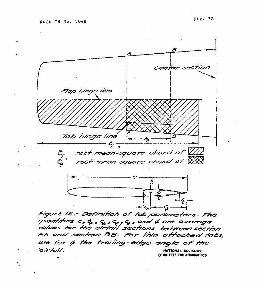
root-mean-square chord of flap
root-mean-square chord of tab
static Pressure on upper surface of airfoil
static pressure on lower surface of airfoil
span of tab
span of flap
increment of flap hinge-moment coefficient
dynamic pressure of air stream over tab
4
'b
?Tf f
Ct
tf
$
Yl
72
y3
y4
6f
a
ai
h
A
P
B
7
R
NACA TN No. 1049
;a.&?rag%~ 'FhoYr,d sf everhang balance, acjrosn. tab span. '
. . .
root;mean-squ& chord of.p;art 'of flap spanned by tab ,. *'.
average tab chord behind tab hinge line . I
average across tab span of flap thickness at flap hinge line
average across tab span of a,irfoil trailing-edge angle
distance from of flap
distance from of flap
distance from end of tab
distance from end of tab
plane of symmetry to inboard end
. plane of symmetry to outboard end
m. .:
inboard end.pf.flap to inboard
Inboard end of flap to outboard
flap deflection with respect to airfoil chord, degree-s
airfoil angle of attack
induced angle' of attack
taper ratio ! root chord
aspect ratio
basic tab hinge-moment effectiveness curve deduced from section data
' basic tab hinge-moment effectiveness curve deduced from finite-span data
turbulence factor
Reynolds number
NACA TN No. 1049
M Mach number
Kc' preliminary
Kt area-mtient
. chord factor
btsff 2 factor
'(. >. bfzi2
,
Kb balance factor
trailing-edge-angle factor 0-3
revised chord factor +
rate of change of tab deflection
- 0.026#)
with respect to _ d6f flap deflection for a linked tab
Subscripts
w f flap .' .
t tab
b balance .
a' trailing-edge angle
C chord
The subscripts to partial derivative8 denote the factotis held constant when the partial derivative is taken.
DATA AND SCOPE
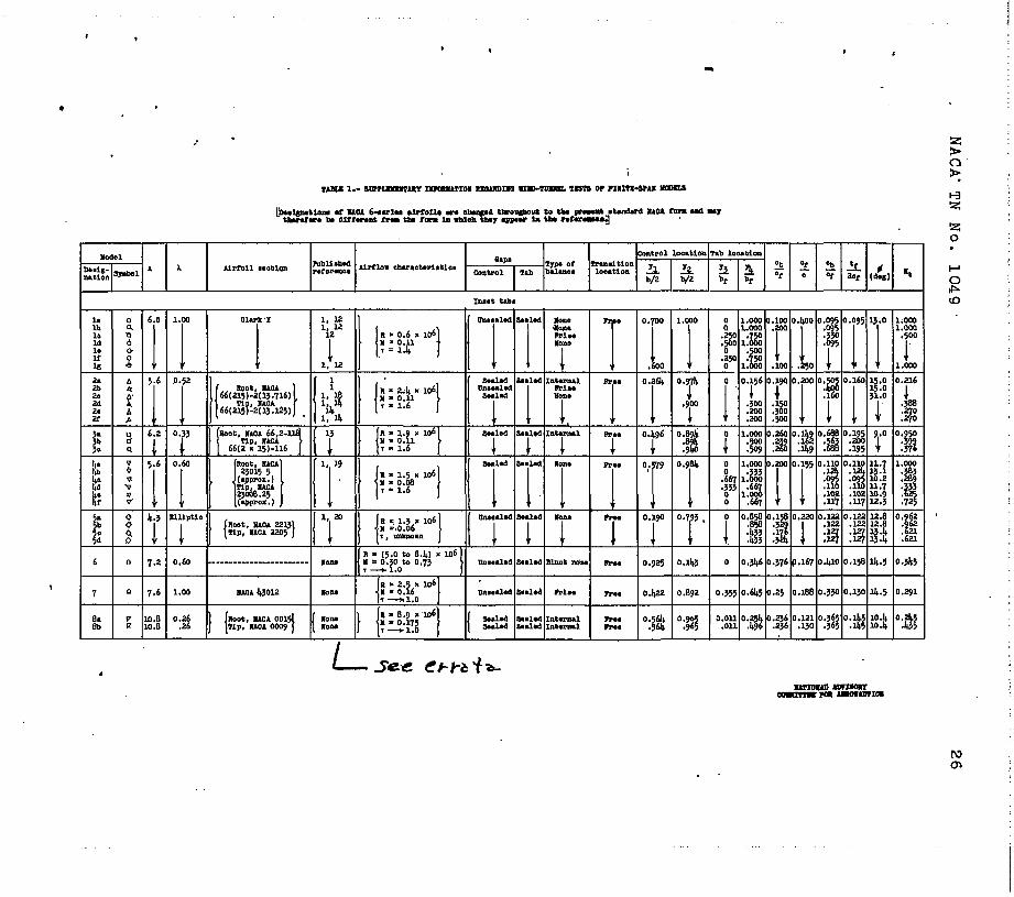
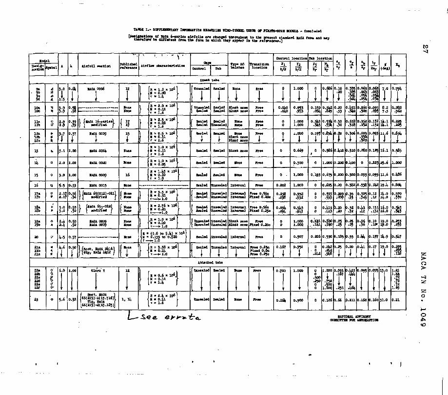
The data used in the correlation were obtained from pressure-distribution tests on NACA 0009 sections smma- rized in reference 2 and from force tests on various model configurations, the Characteristics of which are given.in tables I and II. --These data came from the following
6 NACA TN No. lU47
range3 of tab variables? tab-flap chord ratio from 0.10 to 0.50, flap-airfoi1,cho.M ratio from 0.12 to 0.60, and trailing-edge angle from To to 31°. Sufficient data
.were avaflable from which to draw quantitative conclusions concerning the effects of changing the size of the tab relative to the flap-airfoil combinatLon, the effect of trafling-edge angle, and the effect of control-surface overhang balance on the tdb hinge-moment effectiveness. Insufficient-data were available to determine quantita- tively the effect of the parametgrs that varied the tab hinge-momLent *effectiveness by changing the boundarg- layer thickness over the tab, SuPficfent data were available, however, upon which to base qualitative con- clusions concerning such effects.
BASIC ASSUMPTIOEIS
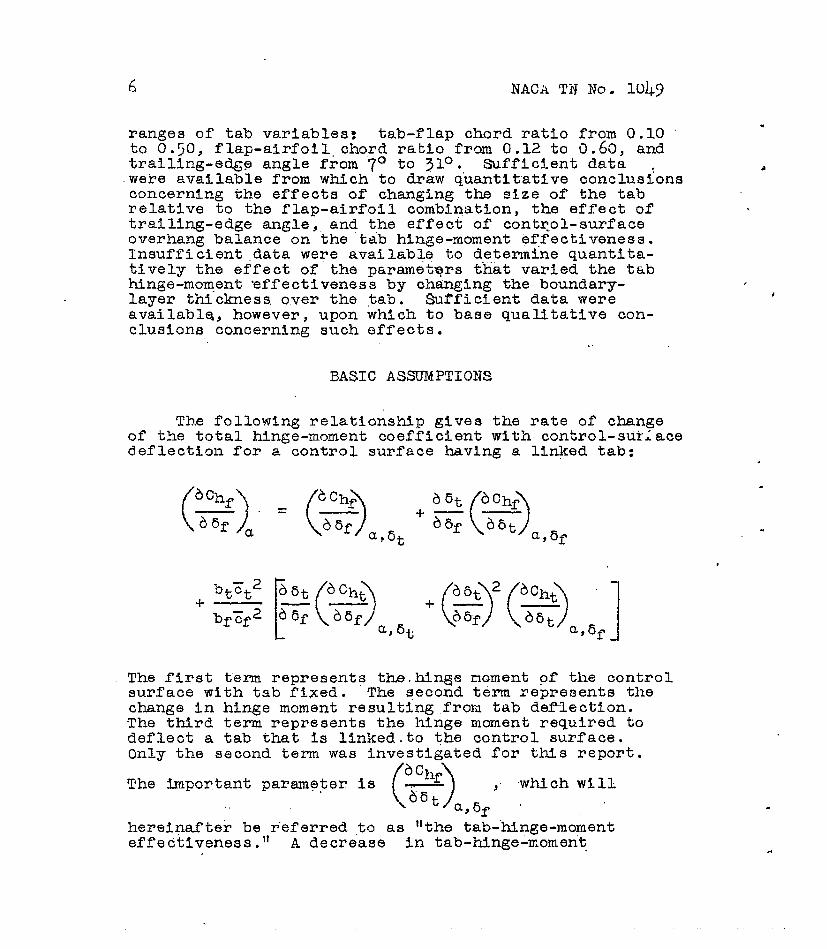
The following relationship gives the rate of change of the total hinae-moment coefficient with control-suriace deflection for a-control surface having a linked tab:
+ btct2
bfcf2
The first term represent3 the.hingje moment of the control surface with tab fixed. The second term represent3 the change in hinge moment resulting from tab deflection. The third term represents the hinge moment required to deflect a tab that is linked.to the control surface. Only the second term was investigated for this report.
The impor,tant parameter is .
hereinafter be referred to as "the tab-hinge-moment effedtlveness." A decrease in tab-hinge-moment-
-
I

, . .
NACA TN No. 1047 7
effectiveness ~3.11 correspond to.numerical values of
"becoming nearer zero. L . . .i
. . Under tile assumptions o;f
ffnite-span-tinge-moment
and may be estimated from section data"'& ':,
means of 'the following equations (ice reference 211::.
= 1
bf 2 b/2 Ef a, et
cf 2d 9
0 b/2
and :
=
‘, 6f
1'
bf Ef2
b/2 a
cf2d
Jjf
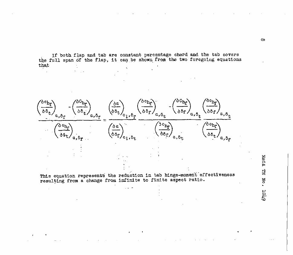
If both flap and tab are constant percentage cWl?d and the tab covers the f’ull span df the flap, it car_ .pe shown, from the two foregoing equations ui&$ . .
This equation represent% the reduhtion in tab Mnge-momen%‘efI’ectivenes,s resulting from a change from infinite to finite aspect ratio.
.- -

.
c
NACA TN So. 1049 9
For usual tab-flap .chord ratios of about 0.2, the data of reference 7 may be used to show that
Table II of reference 215ndicates that for aspect ratios fn the vicinity of A =6
.
and figures 142 and I-47 of reference 2 indicate that
1.0
A reduction of about 20 percent can therefore be expected in tab hinge-moment effectiveness when correcting fnfinite aspect-ratio results to a.finite aspectratio of about 6. The aspect ratios .of the model configurations of table I ,
10 NACA TN I?o. 1049
generally vary through only a relatively small rang8 so that the difference resulting ftiom'changes in aspect ratio between the values of th8 tab hinge-moment effeC- tlveness for these models will.generally be much less than 20 percent and can b8 neglected.
For partial-span tabs the effects of aerodynamic induction in reducfng the,J.dad over the tab and flap are partly compensated by the load induced by the tab on the part of th8 flap-located at the sides of the tab. The aspect-ratio corrections, therefore, are probably greatest for full-span tabs.
The values of ,, ,
used-in the analysis
were, except when otherwlse stated, measured at approxi- . mately zero angle of attack anp flap .8'eflection. These values can be expected td.r,epresent the, tab effect In a tab-deflection range of a.pproxlmatelg *lo degrees. When tests were made with the tab linked,*to-the flap,
ochf
( >
._ - -.'
66t was-determined by mez%ns'of the equation .' .
a,+ already presented for the hinge moments of a flap with a linked tab.
RESULTS AN3 DISCUSSION
The results of the analysis are .presented in two parts as follows: (1) a correlation of the data suitable for quantitative analysis in a form useful for design purposes, and (2) a collection of the-remaining data in a form that indicates the direction and general magnitude of th8 effects resulting from changes in the remaining variables.
quantitative Analysis
of
the
The correlation cons% empirical relatio&3ips
tab hinge-moment eff'ec
sted-mainly in the-determination to renrasent the variation of
with flap

NACA TT\T Xo. 1049 11
_., ad tab chord, with contro.r-surface baJ.anpe, and with trailing-edge angle. Section data for only one trailing- edge angle were available in suffici.ent quantity to determine the variation of the.tab hinge-moment effec- tiveness with flap chord. The assumption that this expression applfes also to the finite-span data, regard- less of trailing-edge angle , made it possible to determine an expression for the variation with trailing-edge angle by iteration. This expression was then'assumed to apply also to section data.
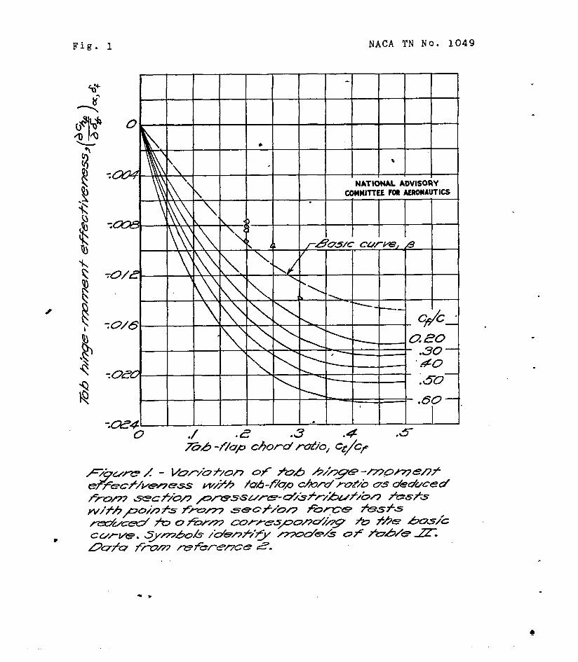
Effect of'flap chord.- Figure 1 shows data from fig- ure"l&t of reference 2 on the variation of the section tab hinge-moment effectiveness with flap-airfoil chord' ratio and tab-flap chord ratio. These data are not cor- rected for the effects of tunnel walls. For the tab-flap chord ratios shown in figure 1, the following empirical. . expression, which would reduce the family of curves to one basic curve, was determined:
%’ = 1 + 0.51 22 ‘>
-0.69 Cf kCf c
Dividing the measured values of the section tab hinge- moment effectiveness by '.I&' represents an extrapolation to a basic curve p, which is also shown in figure 1. The variation of the section tab hinge-moment effective- ness for any flap-airfoil chord ratio Can now be written
If equation (2) is assumed to apply in three- dimensional flow, the hinge-moment coeffI.cients must be based only on the span of the control surface occupied by the tab and on the root-mean-square chord of this same part of the control surface. The hinge-moment coeffi- cients can be based on these quantities as follows:

12 NACA TN No. 1049
(3)
where '.
btzfl 2
Kt = bfzf2'
Effect of balance.- Because the data of figure 1 apply only to contxsurfaces without balance, an expres-
. skon representing the effect of balance must be Inserted in equation (‘3) as follows: .
where
Kb = ',-
= KbKtKc' p (4)
tf 2 ()I 2cf
tf The term - 2cf
corrects for that part of the overhang
which contributes no balancing moment. r The factor %t' * -e-
a c.y, p
(. '
-is the ratlo of the effective pressure over
2 '- -- .- 66: /
Jdf- the bRiELIce to a fictitious rectangularly distributed effective pressure over the flap. Calculations based on
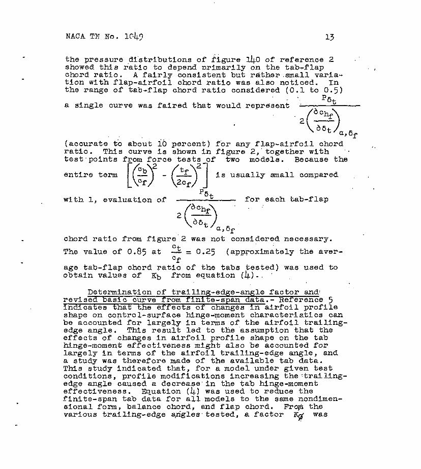
the pressure distributions of figure L!+O of reference 2 .' showed this ratio to depend urimarily on the tab-flap chord ratio. A fairly consistent but r&ther.small varla- tion with flap-airfoil chord ratio was also noticed. In the range of tab-flap chord ratio considered (0.1 to 0.5)
D,
a single curve was faired that would represent . '"t
(accurate to about ib percent) for any flap-airfoil chord ratio. This curve is shown in figure 2,'together with 'm test-points two models. Because the
entire term fs usually small compared I
with 1, evaluatfon of % for each tab-flap
chord ratio from figure'2 was not considered necessary.
The value of 0.85 at 2 = 0.25 (approximately the aver- Cf
age tab-flap chord ratfo of the tabs tested) was used to obtain values of Kb from equation (4).. '.
Determination of trailing-edge-angle factor and: revised basic curve from finite-span data.- Reference 5 indicates that the effects of changes in airfoil profile shape on control-surface hinge-mom&t characteristics can be accounted for largely in terms of the airfoil trailing- edge angle. This result led to the assumption that the effects of changes in airfoil profile shape on the tab hinge-moment effectiveness might also be accounted for largely in terms of the airfoil trailing-edge angle, and a study was therefore made of the available tab data. This study indicated that, for a model under given test conditions, profile modifications increaslng the:trailing- edge angle caused a decrease'in the tab hinge-moment effectiveness. Equation (4) was used to reduce the finite-span tab data for aI1 models to the same nondimen- sional form, balance chord, and flap chord. From the various trailing-edge angles,tested, a factor q was

determined to account for the variation of tab hinge- moment effectiveness with trailing-edge angle. tion (4) was then written
Equa-
= K$KbKtKc 1 (j a+
(5)
A comparison of the data and equation.(5)'showed that.the variation of p p resented in figure.1 did not represent. the available finite-span data; therefore, K$ ,and B (a revised basic curve) were unknown and had to be deter- mined by iteration. The following empirical expressions resulted:
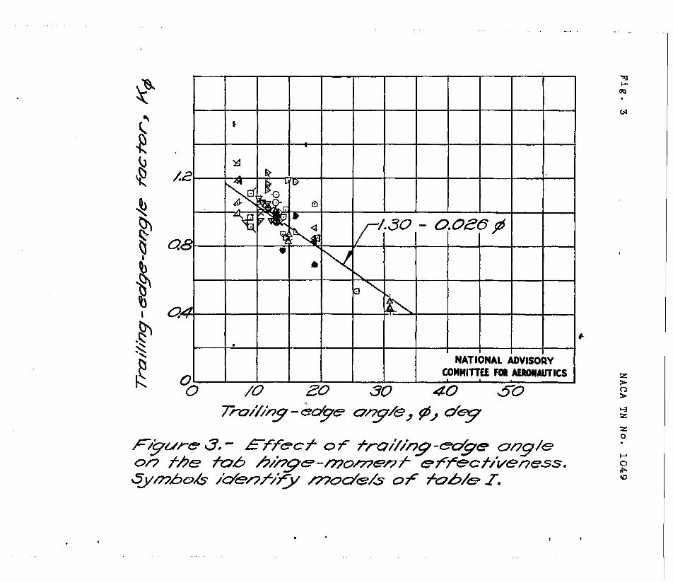
lcId = 1.3 - 0.02.6$
Ct 0.72
0 .
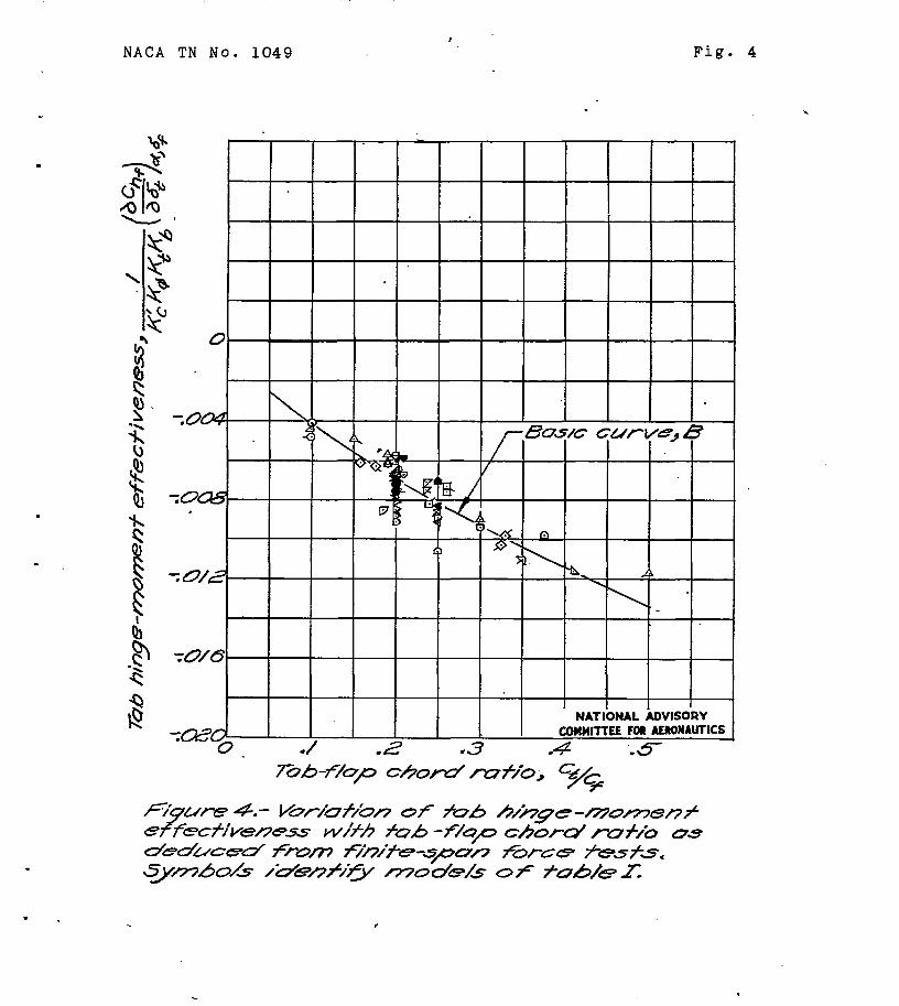
B= -O*OZ2 Cf (7)
Plots of these equa:tLons, with test points from the available finite-span data, respectively.--
are:sho>yn In: figures 3 and 4,
In order @give some indfcation'of the comparison of two-dimensional force-test data with the pressure- distribution data of figure 1, the available force-test data obtained from mope1 configurations described in table II are .&own in figure 1. These data were reduckd to a form corresponding fro the basic curve (3. The trailing-edge-angle factor deauce'd from finite-span data was assumed to apply..
.
Substituting B for .Q and inserting the trailing- edge-angle factor permits equation (4) to be written
I Ct 0.72
= -0.022 K$&&&’ of 0
(8)
a, 6f
NACA TN 60. 1@+9 15
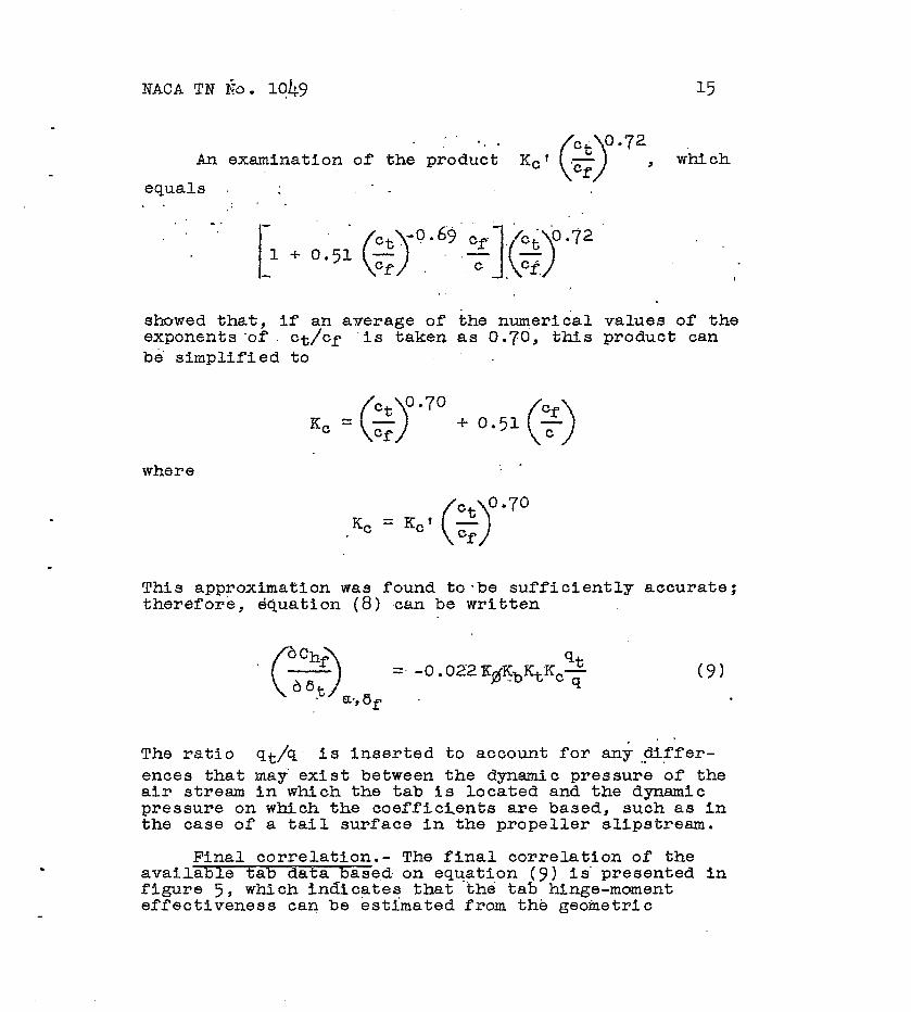
An examination of the prod&t Kc' 3 which
equals
showed that, if an average of exponents 'of. ct/cf 'is taken be simplified to
f Ct o-70 Kc = d Cf
the numerical as 0.70, thfs
+ 0.51 % 0
,
.
values of the product can
where
CRC1 Ct 0.70 .Kc 0 Cf
This approximation was found tombe sufficiently accurate; therefore, equation (8) can be written
(9) .
. The ratio q&q. is inserted to account for an$,.ti.ffer- ences that ma? exist between the dynamic pressure of the aFr stream in which the tab is located and the dynamic pressure on which the coefficLents are based, such as in the case of a tail surface in the propeller slipstream.
Final correlation.- The final correlation of the available tab data base,d, on equation (9) is' presented in figure 5, which lndicsteg that the tab hinge-moment effectiveness can be estimated from the geometric
16 ibCA TX Xo.
characteristics of the tab-flap-airfoil combination use of equation (9).
l&V
bY
The determination of the quantities expressed by equations (6) and (7) was made rather difficult by scatter caused by boundary-layer changes resulting from changes in transition location, flap gap, .turbulence, nnd Reynolds number; furthermore, in every ,caae, insufficient data were available to.determine quantitatively the effect of these variables for inclusionin the correlation. For this reason equations (6) and (7) probably do not give the exact magnitude of the effect but, since both equa- tions introduce only relatively small changes from the original pressure-distribution data, they were considered satisfactory. An examination of table I shows that about 90 percent of the availtible finite-span tab data was for sealed tab gaps. The correlation can therefore be con- sidered as based on the tab-gap-sealed condition.
Special case of thin attached tabs.- Tabs are fre- quently applied to control surfaces simply by attaching a piece of sheet metal that extends behind the trailing edge. Characteristics of such attached-tab model con- figurations are included in table I. Values of the flap- airfoil chord ratio and the tab:flap chord ratio are based on airfoil and flap chords extended by the chord of the tab. By use of these values of the flap-airfoil and tab- flap chord rat.ios with the trailing-edge angle of the airfoil in equation (9)., the attached-tab results were found to agree reasonably well with the previous corre- lation of results for inset tabs as shown in figure 5.
It should be remembered that when an attached tab
is applied to a control stirfake, BChf
( > A .
da 6yr6t oChf
and - ( 1
change somewhat as a result of the be,
a& a1tere.d chord and trailing-edge angle.
g;light data.- Flight data are available for several tabs ir..3';a e d on elevators. The characteristics of these tabs are,shown in table III. Figure 6 shows data typical of the flight measurements from configuration 2, table III. These data show that as the Indicated airspeed
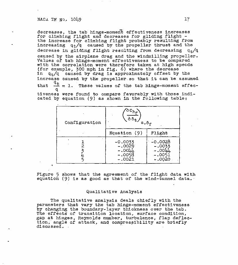
decreases, the tab--hinge-mornen% effectiveness Increases for climbing flight and decreases for gliding flight - the increase for climbfng flight probably resulting from increasing 9th caused by the propeller thrust and the decrease in glidfng flight resulting from decreasing qt-q caused by the airplane drag and the windmilling propeller. Values of tab hinge-moment effectiveness to be compared wfth the correlation were therefore taken at high speeds (for example, in 9th
300 mph in fig. 6) where the decrease caused by drag is approximately offset by the
increase caused by the propeller so that it can be assumed qt that -=l. These values of the tab hinge-moment effec- 9
tivenesa were found to compare favorably with those indi- cated by equation (9) as shown tn the following table:
. Configuratfon . W+
Equation (9) 1 Flight t
I I
: -.0051
5 -.OOZl *.oc)20, . .,
Figure 5 shows that the agreement of the flight data with equation (9) la as good as that of the wind-tunnel data:
Qualitative Analysis
The qualitative analysis deals chiefly with the parameters that vary the tab hinge-moment effectiveness by changing the boundary-layer thickness over the tab. The effects of transition location, surface condition, gap a't hinges, Reynolds number, turbulence, flap deflec- tion,' angle of attack, and compressibility are briefly discussed.

18 NACA TN No. 1049
Effect of transition. location.- A decreased tab hinge:mqent effectiveness wou-ld be expected .to result from thickening the boundary layer bytieving the tranai- tion forward. Such a decrease in effectiveness is shown in figure 5 by the available data on transition location. The solid symbols shown correspond to data for the same models as. the open symbols of the same ahape,except that the transition has been moved forward approximately as, indicated by table I. These data indicate that with air- foils having surface condition such that transitIon is at approximately maximum thickness, reductions in the tab hinge-moment effectiveness occur-as-a result of rn.oving the tranaition.ta the vicinity of.the leading edge. For airfofla having a well-defined low-drag range a. sudden change in the tab hipge-moment effectiveness can therefore be expected at flap defle-ctions and angles of attack corresponding to the limits of the low-drlg range.
Effect of surface conditJon.- Roughness will lead to a decrease in tab hi-e-moment effectiveness when its addition causes the tra'nsition to move forward. Unpub- lished data indicate that, even'when extensive laminar flow is not realized, an appreciable increase in boundary- layer thickness will result from the addition of roughness in the turbulent boundary layer; consequently, a corre- spending decrease in tab hinge-moment effectfveneaa will occur.
Effects of flap and tab gaps.- The effects on tab characteristics of gap at tab and flap hinges result from a tendency of the .f%ow Induced through the-gap by tab deflection to change the boundary layer over the tab. The data of.reference 3 on the effect of flap gap (fig. 7) indicate that., in the usual range of <flap .gapq, (0 to 0.005~); the tab hinge-moment effectiveness *decreases with increasing gap. Figure 40 of reference 2 indicates that the pressure Tesylting from tab deflection at the tab hinge may be, for tab-fldp chord ratios corn- monly used, three to five times that at the flap hinge. Much larger reductions of t-ne%tab hinge.-moment effective- nesa.are therefore to be expected from unsealing the tab gap than.from unsealing the flap gap. The only comparable data on the effecta.of tab gap,are obtained from tests of models 11(a) .andll(b) (table I) and show that unsealing a 0.0016~ gap reduced the tab hinge-moment effectivtjneaa about 20 percent. Less reliable datainticate the poaai- bility of even larger reductions. Tab gaps obviously should be sealed.
.
NACA TN $?o. 1049 19
Effect of Reynolds number.- Increasing the Reynolds number has two .effecta on the boundarv laver. First. increasing the Reynolds number tends 'to thin the boundary layer with the result that the tab hinge-moment effec- tiveness is fn'creaaed. Second, as the boundary layer becomes thinner the size of roughness particles or surface irregularities on the airfoil effectively increases rela- tive to the boundary-layer thickneas,ao that a Reynolds number is reached at which the roughness causes the transition to move forward. This forward movement of the transition with consequent increase In boundary-layer ttickneas at the trailing edge results in a decreased tab hinge-moment effectiveness. The tab hinge-moment effectiveness may, therefore, either increase or decrease with Reynolds number. Whether an increase or a decrease occurs depends on the range of Reynolds number under conaFderation and on the surface condition of the airfoil.
JZffect of turbulence.- Decreasing the turbulence in the air stream over the tab-flap-airfoil combfnation tends to result in a more extensive laminar-flow region. A thinner boundary layer over the tab with a corresponding increase in the tab hfnge-moment effectiveness can there- fore be expected.
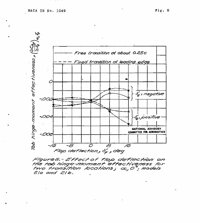
Fffect of flap deflection and angle of attack.- The tab hinge-moment effectiveness data used thus far in the analyaishavebeen measured at zero flap deflection and approximately zero angle of attack. For control-surface deflectlona other than zero the tab hinge-moment effec- tiveness appears to become somewhat discontinuous at 6t=Oo, with the result that two values of the effectiveness are obtained for each fla@ deflection - one corresponding to negative and one to positive-tab deflec- tions. Figure 8 shows typical variations of. two such values of the tab hinge-moment effectiveness wrth flap deflection and indicates that control-surface deflection - decreases the effectiveness of the balancing tab (6f and 6t -having opposite signs) and increases the effec- tiveness of the unbalancing tab (6f and 6t having like signs). The effect shown iti figure 8 increased with forward movement of the transition and the corresponding increasing boundary-layer tnicknesa. An investigation of
20 NACA TN MO. 1049
the effect of small angles of attack on the tab hingo- moment effectiveness did not lead to ~y'consistent results. .Figure 9, which shows the increment of control- surface hinge-moment coefficient corres onding to posi- tive and negative tab deflections of 10 8 (reference 10) was included, however, because it. indicates that &tab may retain a reasonable part of its hiwe-moment eff'ective- ness through and beyond the stall.
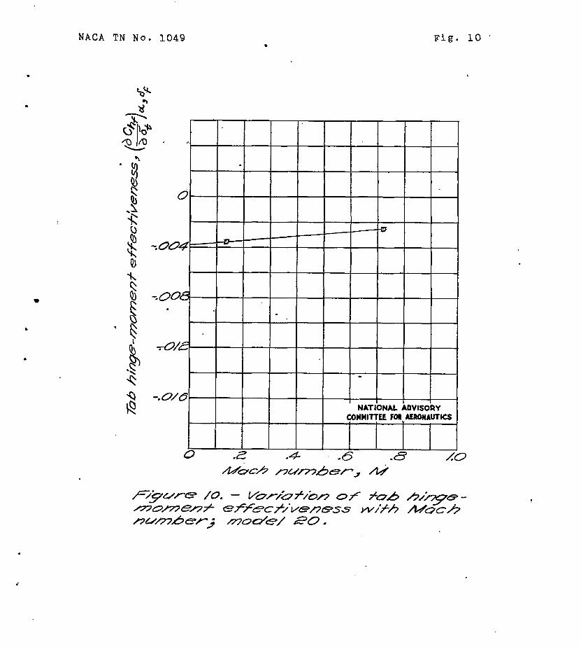
Effect of compressibility.- Because of the increased boundary-layer thickness associated TMith Mach numbers approaching-the critical, a decrease in tab hinge-moment effectiveness is probably to be expected as the-Mach num- _ ber increases. Such a decrease is shown for model 20 (table I) in figure 10. Figure 11 shows the variation of hinge-moment coefficient with control-surface deflection for an aileron-tab combination having two linkage ratios and at different Mach numbers. The moat important indi-
. cation of the data of figures 10 and 11 is that a tab may retain a relattvely large part of Its effectiveness through the subcritical range of Ma&h number,
DESIGN PROCEDURE
In order to design a tab to produce a desired.change in the hinge-moment characteristios of a control surface equation (V), which gives the change in control-surface hinge moment per degree tab deflection, can be used; thus,
= -0.022 v qt
Kb Kt % p a,+
Ffgurc 12 presents a diagram of a typical tab-flap-airfoil combination, on which are defined the -parameters that determine the numerfoal values of.the factors Kg, Kb,
Kt and K,. These parameters may be used to determine K$ from the equation
v = 1.3 - 0.026$
.
NACA TN No. 1049 21
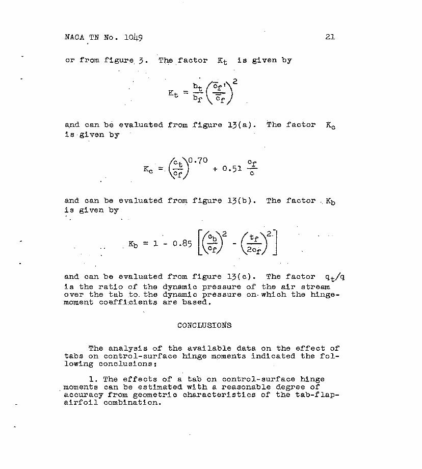
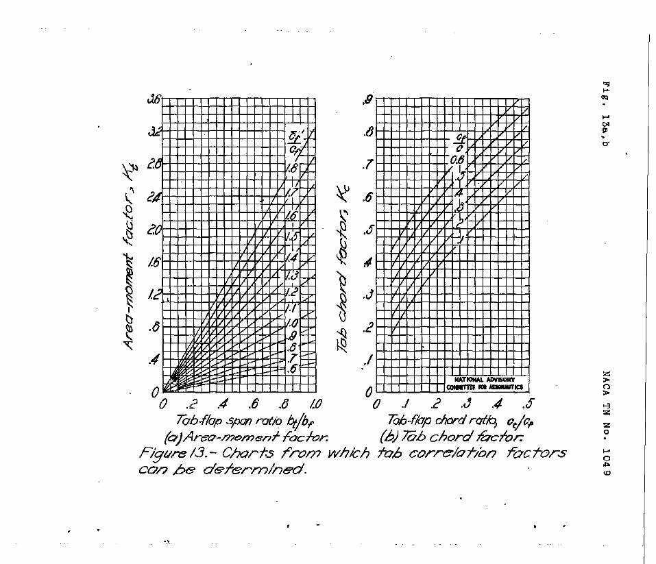
or from figure, 3. The factor Kt is given by
and can be evaluated from figure 13(a). The factor Kc is'given by .
K,’ =-, 2 0.70
0 + 0.51 z
and can be evaluated from figure 13(b). The factor ..Kb is given by .
and can be evaluated from figure 13(c). The factor 9th is the ratio of the dynamic pressure of the air stream over the tab to-the dynamic pressure on.which the hinge- moment coeffkients are based.
The analysis of the available data on the effect of tabs on control-surface hinge moments indfcated the fol- lowing conclusions:
1. The effects of a tab on control-surface hinge .moments can be estimated with a reasonable degree of
accuracy from geometric characteristics of the tab-flap- airfoil combination.

22 NACA TN No. 1049
2. The.tab hinge-moment effectiveness is reduced by increasing the trailing-edge angle or by any alteration of the airfoil surface condition or of the air stream, such as moving the transil;fon forward, roughening the surface, or increasing. the turbulence, that tends to increase the boundary-layer thickness near the trailing edge.
3. The tab hinge-moment effectiveness may either increase or decrease with Reynolds number, Whether an increase or a decrease occurs depends on the range of Reynolds number under consideration and on the surface condition of the airfoil.
4. Gaps at flap and tab NnGes reduce the tab hinge- moment effectiveness and the reductfon resulting from tab gap general&y is so large as to make seals advisable.
5e A reasonable part of the tab hinge-moment effec- tiveness may prevail through and beyond the stall.
6. The tab hinge-moment effectiveness decreases with control-surface deflection for a balancing tab and increases with deflection for an unbalancing tab.
7, Increasing the Machnumber probably decreases the tab hinge-moment effectiveness; however, a relatively large part of the effectiveness may be retained through the subcritical range of Mach number.
Langley b%emorial Aeronautlcal Laboratory NatIona> Advisory Committee for Aeronautics
Langley Field, Va., April 22; 1946
NACA TN Xo. 1049 23
REFERENCES* .
. 1. Rogallo, F. M.: Collection of Balanced-Aileron Test
Data. NACA ACR No. bAl1, 1944. .
2. Sears, Richard 1-i Wind-Tunnel Data on the Aerodynamic Characteristics of Airplane Control Surfaces. NACA ACR No. 3LO8, 1.943. _ - I.
3= Rogallo, F. M., and Lowry, John G.: Re/sum& of Data for Internally Balanced Ailerons. 1943.
NACA RB, March
4.P ' ursEfr, 'Paul S., and Toll, Thomas A.:. Analysis of Available Data on Control Surfaces Hating Plain- Overhang and Frise Balances. G-t-4.
NACA ACR No. L4E13,
5. Purser, Paul E.,.and Gillis, C1arence.L.: Preliminary Correlation of the Effects of Beveled Trailing Edges on the Hinge-Moment Characteristics of Control Surfaces. NACA CB No. 334, 1943.
6. Lowry, John G,: Re'sume' of Hinge,Moment Data for Unshielded Horn-Balanced Control Surfaces. NACA RB No. 3F19, 1943.
7. Swanson, Robert S., and Crandall, Stewart M.: Analysis of Available Data on the Effectiveness of Ailerons without Bposed Overhang Balance. 194-4.
NACA ACR NQ. L&201,
8. Sears, Rfchard I.: Wind-Tunnel Invcsttgation of Control- Surface Characteristics. I - Effect of Gap on the Aerodynamic Characteristics 0f.a.n NACA 0009 Airfoil with a 30-Percent-Chord Plain Flap. 1941.
NACA ARR, June
9. Sears, Richard I., and Liddell,' Robert B.: Wind-Tunnel Investigation of Control-Surface Characteristics. VI - A 30-Percent-Chord Plain Flap on the NACA 0015 Airfoil. NACA ARR, June 1942.
10. Gillis, Clarence L., and Lockwood, Vernard E.: Wind- Tunnel Investigation of Control-Surface Character- istics. XIII - Various Flap Overhangs Used with a 30-Percent-Chord Flap on an NACA 66-009 Airfoil. NACA ACR No. 3G20, 1943. .
24 NACA TN No. 1049
11. Harris, Thomas A.: Reduction of Hinge Moments of Airplane Control Surfaces by Tabs. NO. 528, 1935.
NACA Rep.
12. Rogallo, F.-M., and Lowry, John G.: Wind-Tunnel Development of Ailerons for the Curtiss Xp-60 Air- plane. NACA ACR, Sept. 194.2.
13. Rogallo, F. M., and Crandull, Stewart M.: Wind-Tunnel Investigation of Trimming Tabs on a Thickened and Beveled Aileron on a Tapered tiw-Drag Wing. ACR, March 1943.
NACA
14. Sears, Richard I*, and Hoggard, K. Page, Jr.: Charac- teristics of Plain and Balanced Elevators on a' Typical Pursuit Fuselage at Attitudes Simulating Normal-Flight and Spin Conditions, March 194.2.
NACA ARR,
15.. Garner, I'. Elizabeth; 'Wind-Tunnel Investigation of Control-Surface Characteristics. XX - Plain and Balanced Flaps on an NACA 000 Rectangular Somispan Tail Surface. NACA ARR No. 9 ,lIllf, 1944.
, 16. Lowry, John G., hlaloney, James A., and Garner, I. Elizabeth: Wind-Tunnel Investigation of Shielded Horn Balances and Tabs on a 0.7-Scale Model of XF6F Vertical Tail Surface. mdt.
NACA ACR No. 4Cl1,
17. Purser, Paul El, and McKee, John W,: Wind-Tunnel Investigation of a Plain Aileron with Thickened and Beveled Tralling Edges on a Tapered Low-Drag Wing. NASA ACR, Jan. 1943. "
18. Rogallo, F, -M., and Purser, Paul E.: .Wind-Tunnel Investigation of a Plain Aileron with Various Trailing-Edge Modifications on a Tapered Wing. III - Ailerons with Simple and SprFng-Linked Ralanhfng Tabs. NACA ARR, Jan: 1743.
NACA TN No. 1049 25
13. Bryant, L. W., Burge, C. H., Swoeting, N. E., and Greening, J. R.: Experiments on the Balancing of Ailerons by Geared Tabs and Trailing Edge Strips. 5044, S. & C. 1195a, British A.R.C., Aprfl 5j 1941.
20. Phillips, W. H., and Nissen, J. M.: Flight Tests of Various Tail Modifications on the Brewster XSBA-1 Airplane. I - Measurements of Flying Qualitfes with Original Tail Surfaces. NACA ARR No. 3FO7, 1943.
21. Swanson, Robert S., and Gillis, Clarence L.: Wmi- tations of Lifting-Line Theory for Estimation of Aileron Hinge-Moment Characteristics. NACA CB NO. 3~02, 1343.
.
.
, -
I 1
,
6
I I

, .
,
NACA TN No. 1049 Fig. I
NATIONAL ADVISORY
\, COnMlTTEE Fm AEnowJTIcs .
.

NACA TN No. 1049
.
Fig. 2
l 4
f&TIONAL ADVISORY FOR AERONALITKS J
*0 COMMITTEE
./ -3 -3’ .-#
.-# -5 -5
.
I I I I I I
I I I I NATIONAL ADVISORY COMMITTEE Fol AERWAUTICS
e
. I 1
I
NACA TN No. 1049
.
I I I I t
NATIONAL ADVISORY COWllTlEE FOI AEROWAUTKS
./ -2 .3 -4 -5
,
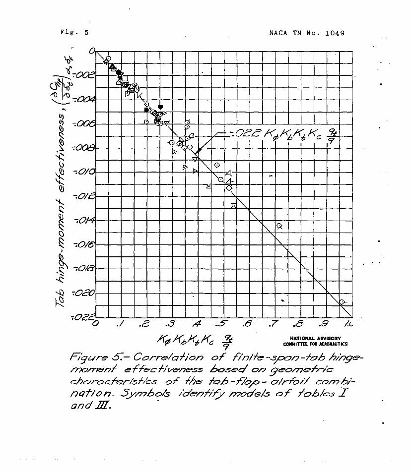
Fig. 5 NACA TN No. 1049
I I I I I I I I
I I I I I I I \
NATIONAL ADVISORY CWIHITTEE F(II AFMRAUTKS
.
. .
.

NACA TN No. 1049 .
Fig. 6
NATIONAL ADVlSORY COMMITTEE FDQ AERDNAUTKS
60 /m /40 BO 220 26a 300
.
J
.
.

Fig. 7 NACA TN No. 1049
z NATIONAL ADVISORY -
COMWITTEE FOI AERDMAUllCS
NACA TN No. 1049 Fig. 8
c
-.OOL
-004
Loa2
-/
\
NAhONAL ADVISORY CDWIITTEE FOI AERDNAUTKS
F -8 0’ 8 /6
.
l
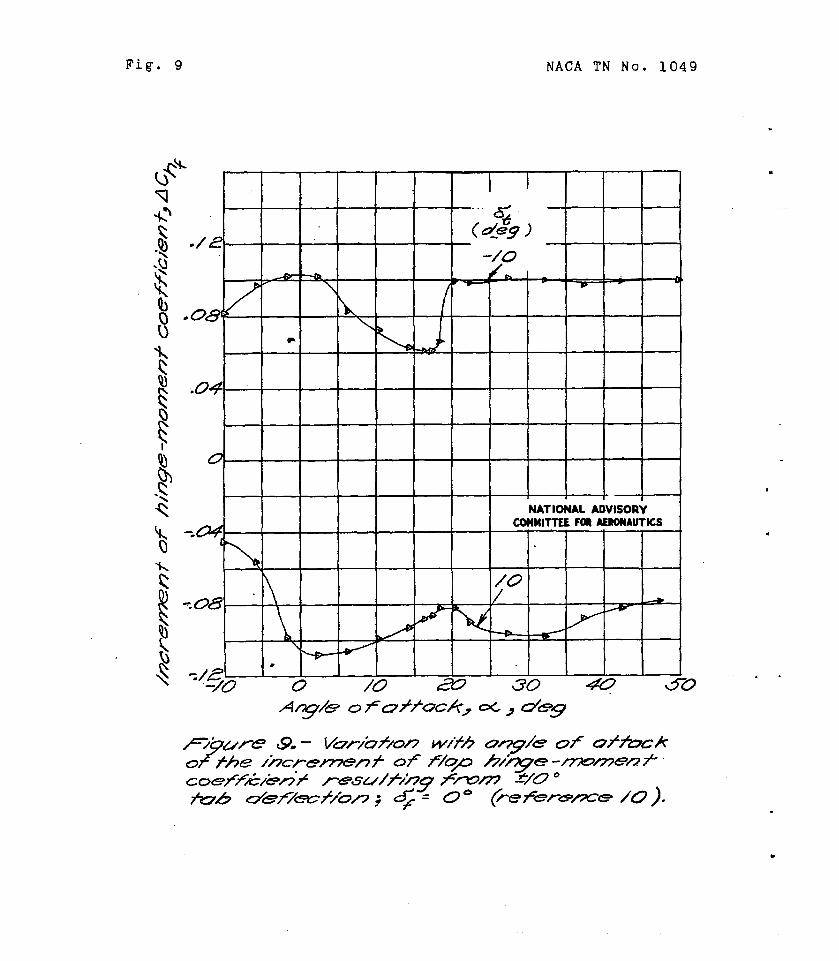
Fig. 9 NACA TN No. 1049
-
8
P F 0 F I
D -\ c
.
.
.
.
NACA TN No. 1049 . Fig. 10 .
w
c
.
70/2
-.0/6 -~~ 1 L L
NATIONAL ADVISORY COHUITTEE FOI AfRDNADlKS
0 .2 -4 -6 .a LO

t i i i i i i i t
-.--
t- 0
El -4 I 0 4 B 12. /6
. . .
MACA TN No. 1049 Fig. 12
z 0 .

NACA TN No. 1049 I
.
Fig. 13~
.88
.64
-60